JP5340660B2 - Vehicle occupant awakening device - Google Patents
Vehicle occupant awakening deviceDownload PDFInfo
- Publication number
- JP5340660B2 JP5340660B2JP2008177979AJP2008177979AJP5340660B2JP 5340660 B2JP5340660 B2JP 5340660B2JP 2008177979 AJP2008177979 AJP 2008177979AJP 2008177979 AJP2008177979 AJP 2008177979AJP 5340660 B2JP5340660 B2JP 5340660B2
- Authority
- JP
- Japan
- Prior art keywords
- awakening
- occupant
- wake
- vehicle
- sleep
- Prior art date
- Legal status (The legal status is an assumption and is not a legal conclusion. Google has not performed a legal analysis and makes no representation as to the accuracy of the status listed.)
- Expired - Fee Related
Links
- 230000007958sleepEffects0.000claimsdescription115
- QVGXLLKOCUKJST-UHFFFAOYSA-Natomic oxygenChemical compound[O]QVGXLLKOCUKJST-UHFFFAOYSA-N0.000claimsdescription12
- 229910052760oxygenInorganic materials0.000claimsdescription12
- 239000001301oxygenSubstances0.000claimsdescription12
- 230000000694effectsEffects0.000claimsdescription10
- 238000013500data storageMethods0.000claimsdescription4
- 238000000034methodMethods0.000description31
- 230000008569processEffects0.000description15
- 238000004364calculation methodMethods0.000description14
- 238000004891communicationMethods0.000description13
- 238000004378air conditioningMethods0.000description8
- 238000001514detection methodMethods0.000description8
- 238000012545processingMethods0.000description8
- 230000007423decreaseEffects0.000description6
- 238000011156evaluationMethods0.000description6
- 230000008859changeEffects0.000description5
- 230000002889sympathetic effectEffects0.000description5
- 206010062519Poor quality sleepDiseases0.000description4
- 238000010586diagramMethods0.000description4
- 210000003128headAnatomy0.000description4
- 210000005037parasympathetic nerveAnatomy0.000description4
- 230000036385rapid eye movement (rem) sleepEffects0.000description4
- 230000002618waking effectEffects0.000description4
- 230000015572biosynthetic processEffects0.000description3
- 238000006243chemical reactionMethods0.000description3
- 210000005036nerveAnatomy0.000description3
- 230000008452non REM sleepEffects0.000description3
- 238000011160researchMethods0.000description3
- 238000003786synthesis reactionMethods0.000description3
- 206010041349SomnolenceDiseases0.000description2
- 238000004458analytical methodMethods0.000description2
- 230000037007arousalEffects0.000description2
- 210000003403autonomic nervous systemAnatomy0.000description2
- 210000000467autonomic pathwayAnatomy0.000description2
- 239000004973liquid crystal related substanceSubstances0.000description2
- 239000011159matrix materialSubstances0.000description2
- 230000003340mental effectEffects0.000description2
- 230000008035nerve activityEffects0.000description2
- 210000001002parasympathetic nervous systemAnatomy0.000description2
- 238000012552reviewMethods0.000description2
- 230000004622sleep timeEffects0.000description2
- 210000002820sympathetic nervous systemAnatomy0.000description2
- 238000001308synthesis methodMethods0.000description2
- 230000009471actionEffects0.000description1
- 238000007664blowingMethods0.000description1
- 210000004556brainAnatomy0.000description1
- 238000005401electroluminescenceMethods0.000description1
- 230000006870functionEffects0.000description1
- 238000003384imaging methodMethods0.000description1
- 238000009434installationMethods0.000description1
- 230000001678irradiating effectEffects0.000description1
- 239000000463materialSubstances0.000description1
- 238000005259measurementMethods0.000description1
- 230000006996mental stateEffects0.000description1
- 238000012986modificationMethods0.000description1
- 230000004048modificationEffects0.000description1
- 238000012544monitoring processMethods0.000description1
- 230000003287optical effectEffects0.000description1
- 238000003909pattern recognitionMethods0.000description1
- 238000003672processing methodMethods0.000description1
- 238000004445quantitative analysisMethods0.000description1
- 230000009467reductionEffects0.000description1
- 230000004044responseEffects0.000description1
- 230000000452restraining effectEffects0.000description1
- 230000033764rhythmic processEffects0.000description1
- 238000005096rolling processMethods0.000description1
- 208000019116sleep diseaseDiseases0.000description1
- 230000002861ventricularEffects0.000description1
Images


Landscapes
- Traffic Control Systems (AREA)
- Navigation (AREA)
- Fittings On The Vehicle Exterior For Carrying Loads, And Devices For Holding Or Mounting Articles (AREA)
- Measurement Of The Respiration, Hearing Ability, Form, And Blood Characteristics Of Living Organisms (AREA)
Abstract
Description
Translated fromJapanese本発明は、車両の乗員を覚醒させるための車両用乗員覚醒装置に関するものである。 The present invention relates to a vehicle occupant awakening device for awakening a vehicle occupant.
車両の走行に伴ってGPS(Global Positioning System:全地球測位システム)等により現在位置を検出し、その現在位置を表示装置上に道路地図と共に表示して、出発地から目的地までの適切な経路を設定し、表示装置や音声出力装置などによって案内する車両用ナビゲーション装置は、ユーザの効率的で安全な運転に貢献している。 As the vehicle travels, the current position is detected by GPS (Global Positioning System), etc., and the current position is displayed on a display device together with a road map, and an appropriate route from the starting point to the destination The vehicle navigation device that guides the vehicle using a display device, a voice output device, or the like contributes to efficient and safe driving for the user.
また、車両用ナビゲーション装置と連携して、目的地あるいは目的地の手前で覚醒用の光を乗員に照射することによって乗員を覚醒させる車両用覚醒照明装置の制御装置が考案されている(特許文献1参照)。 Also, in conjunction with the vehicle navigation device, a control device for a vehicle wake-up lighting device has been devised that wakes up an occupant by irradiating the occupant with a wake-up light at the destination or in front of the destination (Patent Literature). 1).
運転者以外の乗員は眠っていることもある。この場合、特許文献1の例では、目的地あるいは目的地の手前で、乗員は起こされることになるが、睡眠の状態によらず否応なく叩き起こされることになり(あるいは寝たままの状態で放置される)、折角目的地に到着しても、快適に目覚めることができず、暫くの間は半分眠った状態が続き、目的地での楽しみが半減してしまうこともある。 Other passengers may be asleep. In this case, in the example of Patent Document 1, the occupant is woken up at the destination or in front of the destination, but is inevitably struck regardless of the sleep state (or in the state of lying down). If you arrive at the corner destination, you will not be able to wake up comfortably, and you will remain half asleep for a while, and the enjoyment at the destination may be halved.
また、特許文献1の例では、覚醒のための手段が照明装置しかなく、眠っている乗員が気付かないこともあり得る。 Moreover, in the example of patent document 1, there is only a lighting device as a means for awakening, and a sleeping passenger may not notice.
上記問題を背景として、本発明の課題は、目的地に到着する前に、もしくは、乗員が設定した目覚まし時刻に、乗員を快適かつ確実に目覚めさせることが可能な車両用乗員覚醒装置を提供することにある。 With the above problem as a background, an object of the present invention is to provide a vehicle occupant awakening device that can comfortably and reliably wake up an occupant before arriving at a destination or at an alarm time set by the occupant. There is.
上記課題を解決するための車両用乗員覚醒装置は、車両の乗員の生体情報を検出する生体情報検出手段と、生体情報に基づき、乗員の睡眠状態を判定する睡眠状態判定手段と、乗員を覚醒状態とする覚醒タイミングを設定する覚醒タイミング設定手段と、車両に取り付けられ、睡眠状態にある乗員を覚醒状態とする覚醒機器と、乗員の睡眠状態および覚醒タイミングに基づいて、覚醒機器を動作制御する覚醒機器制御手段と、を備えることを前提とする。A vehicle occupant awakening apparatus for solving the above-described problems includes a biological information detection unit that detects biological information of a vehicle occupant, a sleep state determination unit that determines a sleep state of the occupant based on the biological information, and an awakening of the occupant. Awakening timing setting means for setting awakening timing to be in a state, an awakening device that is attached to the vehicle and that makes an occupant in sleep state awakened, and controls the operation of the awakening device based on the sleep state and awakening timing of the occupant and arousal instrument controllerassumes that comprise.
上記構成によって、車内で少し睡眠をとった後に、仕事など何らかの作業を行いたいときに、乗員がセットした目覚め時時刻、もしくは目覚め時刻に近い時刻までで、気持ちよく目覚めることができる睡眠状態で乗員を目覚めさせる事ができる。また、職業上あるいは社会的立場上、降車した際に眠たそうな表情を見せることができない人もいるが、車内で睡眠をとらざるを得ない場合、目的地で降車する前に余裕を持って目覚めることができ、その人のイメージを損なうことを回避できる。 With the above configuration, when you want to do some work such as work after sleeping a little in the car, you can wake up the occupant in a sleep state that can wake up comfortably at the wake-up time set by the occupant or the time close to the wake-up time You can wake up. In addition, there are people who are unable to show a sleepy expression when they get off due to occupational or social reasons, but if you have to sleep in the car, you have plenty of room before getting off at the destination. You can wake up and avoid damaging the person's image.
また、上記課題を解決するための車両用乗員覚醒装置は、車両の現在位置を検出する位置検出手段と、道路地図データを記憶する道路地図データ記憶手段と、道路地図データ上の地点を目的地として設定する目的地設定手段と、車両の現在位置から設定された目的地までの案内経路を検索する案内経路検索手段と、案内経路に基づいて、目的地への到達予想タイミングを算出する到達予想タイミング算出手段と、車両の乗員の生体情報を検出する生体情報検出手段と、生体情報に基づき、睡眠度で表される乗員の睡眠状態を判定する睡眠状態判定手段と、乗員を覚醒状態とする覚醒タイミングを、目的地への到達予想タイミングよりも前に設定する覚醒タイミング設定手段と、車両に取り付けられ、睡眠状態にある乗員を覚醒状態とする覚醒機器と、案内経路上における車両の現在位置,乗員の睡眠状態,および覚醒タイミングに基づいて、現在の睡眠度から乗員が覚醒状態となるまでに要する時間を求め、前記覚醒タイミングからその時間分遡った時刻を覚醒機器動作開始時刻とし、睡眠度が大きい(眠りが深い)ときには、より早く覚醒機器の動作を開始させ、睡眠度が小さい(眠りが浅い)ときには、覚醒タイミングにより近い時刻に覚醒機器の動作を開始させるよう覚醒機器を動作制御する覚醒機器制御手段と、を備えることを特徴とする。
A vehicle occupant awakening apparatus for solving the above problems includes a position detection means for detecting a current position of a vehicle, a road map data storage means for storing road map data, and a point on the road map data. Destination setting means that is set as, guidance route search means that searches for a guide route from the current position of the vehicle to the set destination, and an arrival prediction that calculates the expected arrival timing based on the guide route Timing calculation means, biological information detection means for detecting biological information of the occupant of the vehicle, sleep state determination means for determining the sleep state of the occupantrepresented by thesleep degree based on the biological information, and setting the occupant in the awake state Awakening timing setting means for setting the awakening timing before the expected arrival timing to the destination, and awakening that attaches to the vehicle and makes the occupant in the sleeping state awake And vessels, the current position of the vehicle on the guide route, the occupant of sleep, and on the basis of the awakening time,seek time required from the current sleep degree until the occupant is awake, back its time period from the wake time When the sleep degree is large (sleeping deep), the operation of the awakening apparatus is started earlier, and when the sleep degree is small (sleeping shallow), the wake-up device is closer to the wake-up timing. Awakening device control means for controlling the operation of the awakening deviceso as to start the operation .
上記構成によって、睡眠状態によらず、目的地に到着するまでに快適に目覚めることができ、目的地での楽しみを満喫できる。目的地や案内経路に関する情報は、車両用ナビゲーション装置から取得すれば、車両用乗員覚醒装置のコストを低減することができる。また、職業上あるいは社会的立場上、降車した際に眠たそうな表情を見せることができない人もいるが、車内で睡眠をとらざるを得ない場合、目的地で降車する前に余裕を持って目覚めることができ、その人のイメージを損なうことを回避できる。 With the above configuration, it is possible to wake up comfortably before arriving at the destination regardless of the sleeping state, and enjoy the enjoyment at the destination. If the information regarding the destination and the guidance route is acquired from the vehicle navigation device, the cost of the vehicle passenger awakening device can be reduced. In addition, there are people who are unable to show a sleepy expression when they get off due to occupational or social reasons, but if you have to sleep in the car, you have plenty of room before getting off at the destination. You can wake up and avoid damaging the person's image.
心電,脈波,脳波等の生体情報から、精神的ストレスを解析する研究が行われている(非特許文献1参照)。この研究においては、生体情報から睡眠状態や覚醒状態かどうかを判別できることが記載されている。また、脈拍間隔から自律神経(交感神経,副交感神経)のバランスを算出することで、睡眠状態(覚醒,レム睡眠,ノンレム睡眠)を判別する技術が開示されている(非特許文献2参照)。また、脈波センサは指で脈波を計測するものもあり、小型で車両に搭載可能である。これらの技術を用いれば、乗員に煩わしさを感じさせることなく、かつ睡眠の妨げとなることなく睡眠状態を判定することが可能となる。 Research has been conducted to analyze mental stress from biological information such as electrocardiogram, pulse wave, and electroencephalogram (see Non-Patent Document 1). In this research, it is described that it is possible to discriminate whether it is a sleep state or a wake state from biological information. In addition, a technique for discriminating a sleep state (wakefulness, REM sleep, non-REM sleep) by calculating the balance of autonomic nerves (sympathetic nerves, parasympathetic nerves) from the pulse interval is disclosed (see Non-Patent Document 2). Some pulse wave sensors measure a pulse wave with a finger, and are small and can be mounted on a vehicle. If these techniques are used, it becomes possible to determine the sleep state without causing the passengers to feel bothered and without disturbing sleep.
また、本発明の車両用乗員覚醒装置における覚醒機器制御手段は、乗員の睡眠状態が比較的浅い場合は、該乗員に対する覚醒効果が比較的小さくなるように覚醒機器の動作を制御し、乗員の睡眠状態が比較的深い場合は、該乗員に対する覚醒効果が比較的大きくなるように覚醒機器の動作を制御するように構成される。 Further, the wake-up device control means in the vehicle wake-up device of the present invention controls the operation of the wake-up device so that the wake-up effect on the occupant becomes relatively small when the sleep state of the occupant is relatively shallow, When the sleep state is relatively deep, the operation of the awakening device is controlled so that the awakening effect on the occupant is relatively large.
乗員の睡眠状態によらず画一的な覚醒効果が発生するように覚醒機器を動作させると、覚醒地点に到達する前に乗員が目覚めてしまい、睡眠時間を損した気分になる。上記構成によって、乗員は覚醒地点に到達するまで睡眠をとる(楽しむ)ことが可能となり、車内での時間を有効活用することができる。 If the awakening device is operated so that a uniform awakening effect occurs regardless of the sleep state of the passenger, the passenger wakes up before reaching the awakening point, and the sleep time is lost. With the above configuration, the occupant can sleep (enjoy) until reaching the awakening point, and can effectively use the time in the vehicle.
また、本発明の車両用乗員覚醒装置における覚醒機器制御手段は、覚醒タイミングが到来したとき、乗員が覚醒するように、覚醒機器の動作の制御を行うように構成される。 In addition, the wake-up device control means in the vehicle wake-up device for a vehicle of the present invention is configured to control the operation of the wake-up device so that the wake-up time is reached when the wake-up timing arrives.
上記構成によって、覚醒タイミングが到来したとき、乗員を確実に覚醒させることができる。 With the above configuration, when the awakening timing arrives, the occupant can be reliably awakened.
また、本発明の車両用乗員覚醒装置における覚醒機器制御手段は、乗員の睡眠状態が予め定められた状態にあるときには、覚醒機器の動作の制御を行わないように構成される。 Moreover, the wake-up device control means in the vehicle wake-up device of the present invention is configured not to control the operation of the wake-up device when the sleep state of the occupant is in a predetermined state.
上記構成によって、乗員の眠りが浅いときには、覚醒タイミングが到来したときにのみ覚醒機器を動作すればよいので、バッテリの電力消費を抑制できる。また、生体情報検出手段がセンサとしてシートなどに内蔵されていれば、シート上に置かれているのが乗員か荷物かを区別することができる。例えば、乗員が着座して、別途設けられるシートベルト装着検出手段によりシートベルト非装着を検出した場合に、覚醒機器を動作させて、シートベルト非装着警報を行うこともできる。 With the above configuration, when the occupant's sleep is shallow, it is only necessary to operate the wake-up device only when the wake-up timing arrives, so that the power consumption of the battery can be suppressed. Further, if the biological information detecting means is built in the seat or the like as a sensor, it can be distinguished whether the passenger is placed on the seat or the luggage. For example, when an occupant is seated and seat belt non-wearing is detected by a separately provided seat belt wearing detecting means, a wake-up device can be operated to issue a seat belt non-wearing alarm.
また、本発明の車両用乗員覚醒装置における覚醒機器は、シート位置調整装置,マッサージ器,シート空調装置,エアコン装置,酸素供給装置,オーディオ装置,サンシェード開閉制御装置,車室内照明装置のうちの1つあるいは2つ以上の組合せを用いるように構成される。 The awakening device in the vehicle passenger awakening device of the present invention is one of a seat position adjusting device, a massager, a seat air conditioning device, an air conditioning device, an oxygen supply device, an audio device, a sunshade opening / closing control device, and a vehicle interior lighting device. Or a combination of two or more.
これらの機器のうち、エアコン装置,オーディオ装置(ラジオを含む),車室内照明装置は、殆どの車両に備えられている。他の機器も装着率が上がってきている。上記構成によって、新たな機器を搭載することなく、既存の車載機器を覚醒機器として活用することで本発明の構成を実現できる。 Among these devices, an air conditioner, an audio device (including a radio), and a vehicle interior lighting device are provided in most vehicles. The installation rate of other devices is also increasing. With the above configuration, the configuration of the present invention can be realized by using an existing in-vehicle device as an awakening device without mounting a new device.
以下、本発明の車両用乗員覚醒装置を、図面を参照しながら説明する。図1に車両用乗員覚醒装置300のシステム構成図を示す。車両用乗員覚醒装置300は、睡眠状態演算装置200と車両用ナビゲーション装置100(図1では「ナビ」と表記)と、その他の車載機器(詳細は後述)とを含んで構成される。 Hereinafter, a vehicle occupant awakening device of the present invention will be described with reference to the drawings. FIG. 1 shows a system configuration diagram of a vehicle
睡眠状態演算装置200は、生体信号計測装置201,カメラ202,画像処理部203,操作スイッチ205,表示部206,通信IC213,およびこれらが接続された制御部210を含んで構成される。 The sleep
生体信号計測装置201は、例えば、非特許文献2に記載された光電脈波センサが用いられ、検知した脈波データを制御部210に送る。また、心電あるいは心拍から心室の緊張波であるR波を検知し、その結果を心拍を基に自律神経系の活動レベルとその2つの部門である交感神経系と副交感神経系のバランスの測定分析を行う、例えば米国BIOCOM社製のハートリズムスキャナ(非特許文献3の商品紹介ページ参照)のような機器を用いてもよい。または、フィンランドのEMFIT社のベッドセンサなどを用いることで乗員を非拘束で生体情報を検出することができる。(http://www.europrotech.com/Euro/trade/t_emfit4.html)なお、生体信号計測装置201が本発明の生体情報検出手段に相当する。 The biological
また、生体信号計測装置201として脳波センサを用い、頭部皮膚の電位の変化を検出するようにしてもよい。非特許文献1にあるように、脳波の周波数によって睡眠状態にあるか否かを判定できる。4Hz以下のδ波が発生しているときは深い睡眠状態にあり、4〜8Hzのθ波が発生しているときは眠気がありボンヤリしている状態にある。これらの状態から、脳波の周波数に基づいて後述する睡眠度を算出する。 Further, an electroencephalogram sensor may be used as the biological signal measuring
カメラ202は、例えば周知のCCDやCMOS等の撮像素子を用い、車室内の乗員を撮影可能なように1台または複数台設置される。カメラ202で撮影された画像は、画像処理部203へ送られる。画像処理部203は、公知のパターン認識などの技術によって画像の解析を行う画像処理回路を含んで構成される。画像処理部203では、例えば、カメラ202により撮影された画像に一般的な2値化処理を施すことにより、ピクセル毎のデジタル多値画像データに変換する。そして、得られた多値画像データから、一般的な画像処理手法を用いて乗員の顔画像のような所望の画像部分を抽出する。 One or a plurality of
カメラ202により撮影した頭部の傾き,顔の全体(または部分:例えば目や口)の画像を、睡眠状態における、例えばメモリ212に記憶されたマスター画像と比較することで、眠りの深さを判定することができる。 By comparing the image of the head tilt and the whole face (or part: for example, eyes and mouth) taken by the
操作スイッチ205は、周知のメカニカルスイッチや、表示部206の表示画面上に設けられた周知のタッチパネルとして構成され、乗員の操作により覚醒時刻等の各種の設定入力を行う。なお、操作スイッチ205が本発明の覚醒タイミング設定手段,目的地設定手段,覚醒時刻設定手段に相当する。 The
表示部206は、例えば周知のLCD表示器を含んで構成され、覚醒時刻など各種の設定内容等の必要な情報を表示する。 The
制御部210は、睡眠状態演算部211、および睡眠状態演算部211に接続されるメモリ212を含んで構成される。なお、制御部210が本発明の睡眠状態判定手段,覚醒機器制御手段に相当する。 The
睡眠状態演算部211は、周知のCPU211a,ROM211b,RAM211cを含むマイクロコンピュータとして構成され、CPU211aがROM211bに記憶された制御プログラム211pを実行することで、睡眠状態演算装置200としての機能を実現する。 The sleep
メモリ212は、EEPROM(Electrically Erasable & Programmable Read Only Memory:電気的消去・プログラム可能・読出し専用メモリ)やフラッシュメモリ等の書き換え可能なデバイスによって構成され、睡眠状態演算装置200の動作に必要なデータを記憶する。 The
通信IC213は、車両用ナビゲーション装置100のような他の車載機器とのデータ通信を行うための通信インターフェース回路を含むように構成される。また、通信IC213が本発明の現在時刻情報取得手段に相当する。 The
また、睡眠状態演算装置200は、通信IC213を介して、以下の覚醒機器のうちの少なくとも1つと通信可能に接続される。
・シートECU401(シート位置制御装置):乗員が着座しているシート402の、前後位置,高さ,背もたれ部の角度等の調整を行う(例えば、特開2006−008098号公報参照)。
・マッサージECU403:シート(402)の内部に取り付けられたマッサージ器404の動作制御を行う(例えば、特開2006−198307号公報参照)。
・シート空調ECU405:シート(402)に形成された空気吹出孔に向けて冷却された空調風を吹き出すシート空調装置406の動作制御を行う(例えば、特開2007−126105号公報参照)。
・エアコンECU407:車室内の空調装置である周知のエアコン装置408の動作制御を行う。
・酸素供給ECU409:乗員に酸素を供給する酸素供給装置410の動作制御を行う(例えば、特開平10−230759号公報参照)。
・オーディオECU411:周知のオーディオ装置412の動作制御を行う。
・サンシェードECU413(サンシェード開閉制御装置):車両のリアウィンドウや後部座席ウィンドウ近傍等に取り付けられたサンシェード414の展開/収納の動作制御を行う(例えば、特開平11−062442号公報参照)。
・照明ECU415:ルームランプ等の車内照明装置416の点灯/消灯動作制御を行う(例えば、特許文献1参照)。Sleep
Seat ECU 401 (seat position control device): Adjusts the front and rear position, height, angle of the backrest, etc. of the
Massage ECU 403: Controls the operation of the
-Seat air-conditioning ECU 405: Controls the operation of the seat air-
Air conditioner ECU 407: Controls the operation of a known
Oxygen supply ECU 409: Controls the operation of the
Audio ECU 411: Controls the operation of a known
Sunshade ECU 413 (sunshade opening / closing control device): Controls the operation of unfolding / storing the
Lighting ECU 415: Controls lighting / extinguishing operation of the
図2に、車両用ナビゲーション装置(以下、ナビゲーション装置と略称)100の構成を示すブロック図を示す。ナビゲーション装置100は、位置検出器1,地図データ入力器6,操作スイッチ群7,リモートコントロール(以下リモコンと称する)センサ11,音声案内などを行う音声合成回路24,スピーカ15,メモリ9,表示器10,送受信機13,ハードディスク装置(HDD)21,LAN(Local Area Network) I/F(インターフェース)26,これらの接続された制御回路8,リモコン端末12等を備えている。 FIG. 2 is a block diagram showing a configuration of a vehicle navigation device (hereinafter abbreviated as “navigation device”) 100. The
位置検出器1は、周知の地磁気センサ2,車両の回転角速度を検出するジャイロスコープ3,車両の走行距離を検出する距離センサ4,および衛星からの電波に基づいて車両の位置を検出するGPS受信機5を有している。これらのセンサ等2,3,4,5は各々が性質の異なる誤差を持っているため、複数のセンサにより各々補完しながら使用するように構成されている。なお、精度によっては前述したうちの一部のセンサで構成してもよく、さらに、ステアリングの回転センサ(図示せず)や各転動輪の車輪センサ例えば車速センサ23等を用いてもよい。なお、位置検出器1が本発明の位置検出手段に相当する。 The position detector 1 is a well-known
操作スイッチ群7は、例えば表示器10と一体になったタッチパネル22もしくはメカニカルなスイッチが用いられる。その他に、マウスやカーソル等のポインティングデバイスを用いてもよい。 As the operation switch group 7, for example, a
また、マイク31および音声認識ユニット30を用いて種々の指示を入力することも可能である。これは、マイク31から入力された音声信号を、音声認識ユニット30において周知の隠れマルコフモデル等の音声認識技術により処理を行い、その結果に応じた操作コマンドに変換するものである。これら本発明の目的地設定手段に相当する操作スイッチ群7,リモコン端末12,タッチパネル22,およびマイク31により、種々の指示を入力することが可能である。 It is also possible to input various instructions using the
送受信機13は、例えば道路に沿って設けられた送信機(図示せず)から出力される光ビーコン、または電波ビーコンによってVICS(Vehicle Information and Communication System:道路交通情報通信システム,登録商標)センタ14から道路交通情報を受信、あるいはFM多重放送を受信するための装置である。また、送受信機13を用いてインターネット等の外部ネットワークに接続可能な構成としてもよい。 The transceiver 13 is, for example, a VICS (Vehicle Information and Communication System: registered trademark)
制御回路8は、周知のCPU81,ROM82,RAM83,入出力回路であるI/O84,A/D変換部86,描画部87,時計IC88,およびこれらの構成を接続するバスライン85が備えられている。CPU81は、HDD21に記憶されたナビプログラム21pおよびデータにより制御を行う。また、HDD21へのデータの読み書きの制御はCPU81によって行われる。また、CPU81からHDD21に対してデータの読み書きの制御ができなくなった場合のために、ROM82にナビゲーション装置100として必要最低限の動作を行うためのプログラムを記憶しておいてもよい。なお、制御回路8が本発明の案内経路検索手段に相当する。 The control circuit 8 includes a well-known
A/D変換部86は周知のA/D(アナログ/デジタル)変換回路を含み、例えば位置検出器1などから制御回路8に入力されるアナログデータをCPU81で演算可能なデジタルデータに変換するものである。 The A /
描画部87は、HDD21等に記憶された道路地図データ21m(後述),表示用のデータや表示色のデータから表示器10に表示させるための表示画面データを生成する。 The
時計IC88はリアルタイムクロックICとも呼ばれ、CPU81からの要求に応じて時計・カレンダーのデータを送出あるいは設定するものである。CPU81は時計IC88から日時情報を取得する。また、GPS受信機5で受信したGPS信号に含まれる日時情報を用いてもよい。また、CPU81に含まれるリアルタイムカウンタを基にして日時情報を生成してもよい。 The
HDD21には、ナビプログラム21pの他に位置検出の精度向上のためのいわゆるマップマッチング用データ、道路の接続を表した道路データを含む地図データベースである道路地図データ21mが記憶される。道路地図データ21mは、表示用となる所定の地図画像情報を記憶するとともに、リンク情報やノード情報等を含む道路網情報を記憶する。リンク情報は、各道路を構成する所定の区間情報であって、位置座標,距離,所要時間,道幅,車線数,制限速度等から構成される。また、ノード情報は、交差点(分岐路)等を規定する情報であって、位置座標,右左折車線数,接続先道路リンク等から構成される。また、リンク間接続情報には、通行の可不可を示すデータなどが設定されている。なお、HDD21が本発明の道路地図データ記憶手段に相当する。 In addition to the
ダイクストラ法では、これらのリンク情報,ノード情報,リンク間接続情報を用いて、現在地から各ノードに至るまでの経路評価値(経路計算コスト)を算出し、目的地までの全ての経路評価値の計算が終了した段階で、総評価値が最小となるリンクを接続して目的地までの経路を設定している。この場合の評価値は、道路長・道路種別・道路幅員・車線数・交差点での右左折・信号機の有無などに応じて設定されている。例えば、道路幅員が広いほど評価値が低く、車線数が多いほど評価値が低い。 In the Dijkstra method, using these link information, node information, and link connection information, the route evaluation value (route calculation cost) from the current location to each node is calculated, and all the route evaluation values to the destination are calculated. When the calculation is completed, a link to the smallest total evaluation value is connected and a route to the destination is set. The evaluation value in this case is set according to the road length, road type, road width, number of lanes, right / left turn at the intersection, presence / absence of traffic lights, and the like. For example, the evaluation value is lower as the road width is wider, and the evaluation value is lower as the number of lanes is larger.
各リンクでの経路計算コストの計算は、例えば次式を用いて行われる。経路計算コスト=リンク長×道路幅員係数×道路種別係数×渋滞度。ここで、道路幅員係数とは道路幅に応じて設定される係数であり、道路種別係数とは有料道路等の道路種別に応じて設定される係数である。そして、渋滞度とは、その道路の渋滞度合に応じて設定される係数である。 The calculation of the route calculation cost at each link is performed using, for example, the following equation. Route calculation cost = link length × road width coefficient × road type coefficient × congestion level. Here, the road width coefficient is a coefficient set according to the road width, and the road type coefficient is a coefficient set according to the road type such as a toll road. The congestion level is a coefficient set according to the congestion level of the road.
また、HDD21には経路案内の補助情報や娯楽情報、その他にユーザが独自にデータを書き込むことができ、ユーザデータ21uとして記憶される。また、ナビゲーション装置100の動作に必要なデータや各種情報はデータベース21dとしても記憶される。 In addition, in the
ナビプログラム21p,道路地図データ21m,ユーザデータ21u,およびデータベース21dは、地図データ入力器6を介して記憶媒体20からそのデータの追加・更新を行うことが可能である。記憶媒体20は、そのデータ量からCD−ROMやDVDを用いるのが一般的であるが、例えばメモリカード等の他の媒体を用いてもよい。また、外部ネットワークを介してデータをダウンロードする構成を用いてもよい。 The
メモリ9はEEPROMやフラッシュメモリ等の書き換え可能なデバイスによって構成され、ナビゲーション装置100の動作に必要な情報およびデータが記憶されている。なお、メモリ9は、ナビゲーション装置100がオフ状態になっても記憶内容が保持されるようになっている。また、メモリ9の代わりにナビゲーション装置100の動作に必要な情報およびデータをHDD21に記憶してもよい。さらに、ナビゲーション装置100の動作に必要な情報およびデータをメモリ9とHDD21に分けて記憶してもよい。 The memory 9 is composed of a rewritable device such as an EEPROM or a flash memory, and stores information and data necessary for the operation of the
表示器10は周知のカラー液晶表示器で構成され、ドット・マトリックスLCD(Liquid Crystal Display)およびLCD表示制御を行うための図示しないドライバ回路を含んで構成されている。ドライバ回路は、例えば、周知のアクティブマトリックス駆動方式が用いられ、制御回路8(描画部87)から送られる表示指令および表示画面データに基づいて表示を行う。また、表示器10として有機EL(ElectroLuminescence:電界発光)表示器,プラズマ表示器を用いてもよい。 The
スピーカ15は周知の音声合成回路24に接続され、ナビプログラム21pの指令によってメモリ9あるいはHDD21に記憶されるデジタル音声データが音声合成回路24においてアナログ音声に変換されたものが送出される。なお、音声合成の方法には、音声波形をそのままあるいは符号化して蓄積しておき必要に応じて繋ぎ合わせる録音編集方式、文字入力情報からそれに対応する音声を合成するテキスト合成方式などがある。 The
車速センサ23は周知のロータリエンコーダ等の回転検出部を含み、例えば車輪取り付け部付近に設置されて車輪の回転を検出してパルス信号として制御回路8に送るものである。制御回路8では、その車輪の回転数を車両の速度に換算して、車両の現在位置から所定の場所までの予想到達時間を算出したり、車両の走行区間毎の平均車速を算出する。 The
LAN I/F26は、車内LAN27を介して、睡眠状態演算装置200や他の車載機器,センサとのデータの遣り取りを行うための通信インターフェース回路である。また、LAN I/F26を介して車速センサ23からのデータ取り込みを行ってもよい。 The LAN I /
このような構成を持つことにより、ナビゲーション装置100は、制御回路8のCPU81によりナビプログラム21pが起動されると、ユーザが操作スイッチ群7,タッチパネル22,リモコン端末12の操作、あるいはマイク31からの音声入力によって、表示器10上に表示されるメニュー(図示せず)から目的地経路を表示器10に表示させるための経路案内処理を選択した場合、次のような処理を実施する。 With this configuration, the
すなわち、まず、ユーザは目的地を検索する。目的地の検索方法は、例えば、地図上の任意の地点を指定する方法,目的地の所在する地域から検索する方法,目的地の電話番号から検索する方法,五十音表から目的地の名称を入力して検索する方法,あるいはユーザがよく利用する施設としてメモリ9に記憶されているものから検索する方法などがある。目的地が設定されると、位置検出器1により車両の現在位置が求められ、例えば上述のダイクストラ法等の手法を用いて、該現在位置を出発地として目的地までの最適な案内経路を求める処理が行われる。そして、表示器10上の道路地図に案内経路を重ねて表示し、ユーザに適切な経路を案内する。また、表示器10およびスピーカ15の少なくとも一方によって、操作時のガイダンスや動作状態に応じたメッセージの報知を行う。 That is, first, the user searches for a destination. The destination search method is, for example, a method of specifying an arbitrary point on the map, a method of searching from the area where the destination is located, a method of searching from the telephone number of the destination, or a name of the destination from the Japanese syllabary table There are a method for searching by inputting the number of characters stored in the memory 9 as a facility frequently used by the user. When the destination is set, the current position of the vehicle is obtained by the position detector 1 and, for example, using the technique such as the Dijkstra method described above, the optimum guidance route to the destination is obtained using the current position as the departure point. Processing is performed. Then, the guidance route is displayed on the road map on the
図3を用いて、睡眠状態演算装置200において実行される乗員覚醒処理について説明する。なお、本処理は制御プログラム211pに含まれ、制御プログラム211pの他の処理とともに繰り返し実行される。また、本処理は、生体信号計測装置201を装着した全ての乗員(座席)について行う。また、本処理は、ナビゲーション装置100において、目的地が設定され、さらにその目的地までの経路案内を行っていること、もしくは、操作スイッチ205で、目覚め時刻(覚醒時刻)が設定されていることを前提とする。 The occupant awakening process executed in the sleep
まず、操作スイッチ205を操作し、表示部206の画面表示にしたがって、乗員を覚醒状態とする目覚め時刻を設定する(S11)。無論、目覚め時刻は、乗員毎に異なった設定を行うことができる。また、時刻の他に「10分後」のようなタイマー設定とする構成としてもよい。この場合は、ナビゲーション装置100あるいはCPU211a等から現在時刻情報を取得して、目覚め時刻に換算しておく。 First, the
次に、通信IC213を介して、ナビゲーション装置100から目的地までの到達予想時間に関する情報を取得する(S12)。目的地までの到達予想時間は、ナビゲーション装置100において、車両の現在位置から目的地までの距離を車速センサ23から検出された車速(あるいは走行開始時から現在までの平均車速)で割ることによって算出できる。また、VICSセンタ14等から取得した交通情報(渋滞情報)を用いれば、より精度良く到達予想時間を算出することができる。続いて、ナビゲーション装置100から現在時刻情報を取得し、目的地までの到達予想時間と現在時刻とから、目的地までの到達予想時刻を算出する。そして、到達予想時刻から例えば10分前のような予め定められた時間だけ前を目覚め時刻として算出する。 Next, information about the estimated arrival time from the
なお、ステップS11で目覚め時刻が設定されているときには、乗員による設定を優先してもよい。つまり、ステップS12で算出された目覚め時刻は、目覚め時刻を設定しなかった乗員(座席)に対して適用される。 When the awakening time is set in step S11, the setting by the occupant may be prioritized. That is, the wake-up time calculated in step S12 is applied to the occupant (seat) for which the wake-up time is not set.
また、車両用乗員覚醒装置300にナビゲーション装置100が含まれない構成のときには、ステップS12は実行されない。このときの、時刻情報の生成・取得は、CPU211aに含まれる内部カウンタ(図示せず)で行うか、ナビゲーション装置100に含まれる時計IC88と同様のものを制御部210に含む構成とする。 Further, when the vehicle
次に、生体信号計測装置201から脈波に関するデータを取得し、非特許文献2のように、まず計測した脈波データから脈拍の間隔を取得し,その揺らぎを周波数解析することで,交感神経および副交感神経の活性度を反映する周波数成分(LF:0.1Hz前後およびHF:0.3Hz前後)のレベルを求める。そして、交感神経活動と副交感神経活動の変化を自律神経バランスとして求め、睡眠状態との対応付けを行う(S13)。このとき、睡眠状態は、睡眠度として表される。すなわち、覚醒状態:睡眠度0,レム睡眠:睡眠度1,ノンレム睡眠(非特許文献2に準じて4段階に区分):睡眠度2から5となり、睡眠度5が最も眠りが最も深い状態である。 Next, data on the pulse wave is acquired from the biological
交感神経系成分(LF)と副交感神経系成分(HF)の比(LF/H値)は通常1〜1.5程度であるのに対して、疲労状態ではLF/HF値が増加することが知られている(非特許文献3参照)。LF,HFの状態と自律神経系の作用との関係は、例えば図4のように表すことができる。このとき、LF,HFの値が比較的大きく、LF/HFが予め定められた範囲内にあるとき、睡眠状態であると判定できる。 The ratio (LF / H value) of the sympathetic nervous system component (LF) to the parasympathetic nervous system component (HF) is usually about 1 to 1.5, whereas the LF / HF value may increase in a fatigue state. It is known (see Non-Patent Document 3). The relationship between the state of LF and HF and the action of the autonomic nervous system can be expressed as shown in FIG. 4, for example. At this time, when the values of LF and HF are relatively large and LF / HF is within a predetermined range, it can be determined that the patient is in a sleeping state.
また、非特許文献1の記載に基づいて、乗員の頭部に着けて頭部皮膚の電位の変化を検出する脳波センサを用いて、検出した脳波の状態から睡眠度を算出してもよい。 Further, based on the description in Non-Patent Document 1, the sleep level may be calculated from the detected electroencephalogram state by using an electroencephalogram sensor that is worn on the head of the occupant and detects a change in the potential of the head skin.
次に、覚醒機器(シートECU401他)の動作を開始する覚醒機器動作開始時刻を算出する(S14)。算出方法は、以下のいずれかを用いる。
・例えば、単位時間あたりの睡眠度の減少率(図5のd/dtに相当)が予め定められた値としたときに、その減少率で現在の睡眠度から覚醒状態となるまでに要する時間を求め、目覚め時刻からその時間分遡った時刻を覚醒機器動作開始時刻とする。つまり、睡眠度が大きい(眠りが深い)ときには、より早く覚醒機器の動作が開始され、睡眠度が小さい(眠りが浅い)ときには、目覚め時刻により近い時刻に覚醒機器の動作が開始される。このようにして、覚醒の度合いを略一定として、乗員を急激に起こさないようにすることができる。Next, the awakening device operation start time for starting the operation of the awakening device (such as the seat ECU 401) is calculated (S14). Any of the following is used as the calculation method.
For example, when the rate of decrease in the sleep degree per unit time (corresponding to d / dt in FIG. 5) is a predetermined value, the time required to change from the current sleep level to the awake state at the decrease rate And the time that goes back that time from the awakening time is set as the awakening device operation start time. That is, when the sleep degree is large (sleep is deep), the operation of the wake-up device is started earlier, and when the sleep degree is small (sleep is shallow), the operation of the wake-up device is started at a time closer to the wake-up time. In this way, the degree of arousal can be made substantially constant and the occupant can be prevented from abruptly awakening.
次に、通信IC213を介して、ナビゲーション装置100から(あるいはCPU211aから)現在時刻に関する情報を取得する(S15)。そして、覚醒機器動作開始時刻が到来したか否かを判定する。覚醒機器動作開始時刻が到来しない場合(S16:No)、ステップS12へ戻り、ステップS15までの処理を行う。このように処理を繰り返すことで、乗員の睡眠度が変化しても、その睡眠度に応じた覚醒機器動作開始時刻を算出することができる。 Next, information about the current time is acquired from the navigation device 100 (or from the
一方、覚醒機器動作開始時刻が到来した場合(覚醒機器動作開始時刻を算出した時点で覚醒機器動作開始時刻を過ぎた場合も含む)(S16:Yes)、算出した睡眠度から、睡眠が浅い状態か否か、すなわち睡眠状態がレム睡眠である睡眠度1より大きいか否かを判定する。 On the other hand, when the awakening device operation start time has arrived (including the case where the awakening device operation start time has passed when the awakening device operation start time is calculated) (S16: Yes), the sleep state is shallow from the calculated sleep degree It is determined whether or not the sleep state is greater than the sleep degree 1 that is REM sleep.
睡眠状態が睡眠度1より大きく眠りが深い場合(ノンレム睡眠)(S17:No)、ナビゲーション装置100から目的地までの到達予想時間に関する情報を取得して、目覚め時刻を再計算する(S22)。なお、車両用乗員覚醒装置300にナビゲーション装置100が含まれない構成のときには、ステップS22は実行されない。 When the sleep state is greater than sleep level 1 and deep sleep (non-REM sleep) (S17: No), information on the estimated arrival time from the
次いで、ナビゲーション装置100から(あるいはCPU211aから)現在時刻に関する情報を取得する(S23)。そして、現在時刻と目覚め時刻との差(残り時間)と睡眠度とに基づいて、上述のように、d/dtが略一定となるように、覚醒量を算出する(S24)。 Next, information about the current time is acquired from the navigation device 100 (or from the
次に、覚醒機器が複数ある場合は、上記で算出した覚醒量に相当する覚醒効果を発生できる覚醒機器を選択・決定する。一つの覚醒機器によって上記で算出した覚醒量を発生できない場合には、複数の覚醒機器を組み合わせて用いる。各覚醒機器は、例えば以下のようにして、それぞれ覚醒効果を発生する。
・シートECU401:シート402の背もたれ部を立てるように角度を変化させる。
・マッサージECU403:マッサージ器404が動作中の場合には、現在の動作モードと異なるモードで動作させる。例えば、首・肩をマッサージ中の時には、背中・腰をマッサージする。あるいは、マッサージ力を乗員の設定よりも強くする。マッサージ器404が動作中でない場合には、マッサージ器404を予め定められた時間、予め定められた強さで動作させる。
・シート空調ECU405:シート空調装置406が動作中の場合には、現在の設定温度よりも例えば3℃程度低い(現在の設定温度と異なる)温度となるようにする。シート空調装置406が動作中でない場合には、予め定められた温度で動作させる。
・エアコンECU407:エアコン装置408が動作中の場合には、現在の設定温度よりも例えば3℃程度低い(現在の設定温度と異なる)温度となるようにする。エアコン装置408が動作中でない場合には、予め定められた温度で動作させる。
・酸素供給ECU409:酸素供給装置410により酸素を供給中の場合には、酸素の供給量を変化させる。酸素を供給中でない場合には、酸素供給装置410により乗員に予め定められた量の酸素を供給する。
・オーディオECU411:オーディオ装置412が動作中の場合には、音量を乗員の設定とは異なる状態に変化させる(例えば、音量を大きくする)。オーディオ装置412が動作中でない場合には、予め定められた音量で動作させる。
・サンシェードECU413:サンシェード414が展開されている場合は収納する。
・照明ECU415:ルームランプ,読書灯等の車内照明装置416が消灯中の場合は点灯させる。照明装置416が点灯中の場合は、輝度を変化させたり、点滅させる。Next, when there are a plurality of wake-up devices, a wake-up device capable of generating a wake-up effect corresponding to the wake-up amount calculated above is selected and determined. When a single wake-up device cannot generate the wake-up amount calculated above, a plurality of wake-up devices are used in combination. Each wake-up device generates a wake-up effect as follows, for example.
Seat ECU 401: The angle is changed so that the backrest portion of the
Massage ECU 403: When the
Seat air conditioning ECU 405: When the seat
Air conditioner ECU 407: When the
Oxygen supply ECU 409: When oxygen is being supplied by the
When the
Sunshade ECU 413: Stores the
-Lighting ECU 415: Turns on the
そして、上記で選択した覚醒機器を動作させる(S25)。すなわち、睡眠状態演算部211から通信IC213を介し、選択した覚醒機器に対して、乗員を覚醒させるための動作を行うよう制御指令を送る。 Then, the awakening device selected above is operated (S25). That is, a control command is sent from the sleep
一方、睡眠状態が睡眠度1より小さく眠りが浅い場合(レム睡眠)(S17:Yes)、通信IC213を介して、ナビゲーション装置100から(あるいはCPU211aから)現在時刻に関する情報を取得する(S18)。そして、目覚め時刻に近いか否かを判定する。例えば、目覚め時刻から5分以内であれば、目覚め時刻に近いと判定する。目覚め時刻に近くないと判定された場合(S19:No)、ステップS17に戻り、睡眠状態を判定する。このように処理を繰り返すことで、乗員の睡眠度が変化しても、その睡眠度に応じて覚醒機器を動作させることができる。 On the other hand, when the sleep state is smaller than the sleep degree 1 and the sleep is shallow (REM sleep) (S17: Yes), information on the current time is acquired from the navigation device 100 (or from the
一方、目覚め時刻に近いと判定された場合(S19:Yes)、覚醒量を算出し、覚醒機器を決定する(S20)。この場合の覚醒量は、上述のd/dtとは異なり、乗員を完全に覚醒させることができる量とする。 On the other hand, when it is determined that it is close to the awakening time (S19: Yes), the awakening amount is calculated and the awakening device is determined (S20). In this case, the awakening amount is different from the above-mentioned d / dt and is an amount that can completely awaken the occupant.
そして、上記で選択した覚醒機器を動作させ、乗員を覚醒させる(目を覚まさせる)(S21)。 Then, the wake-up device selected above is operated to wake up (wake up) the occupant (S21).
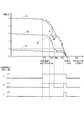
図5に、睡眠状態と覚醒機器の動作タイミングとの関係を示す。まず、Aで示される睡眠状態が深い(睡眠度5)場合について説明する。目的地到達予想時刻をT0,目覚め時刻をT1とする。睡眠状態と覚醒機器の覚醒量とに基づいて、覚醒機器動作開始時刻T3が算出される。覚醒機器動作開始時刻T3が到来すると、睡眠度が徐々に小さく(眠りが浅く)なるように覚醒機器を動作させる。このときの単位時間あたりの睡眠度の減少量(覚醒量)がd/dtとなる。睡眠度は一様に減少するわけではなく上下を繰り返して漸減していく。図3の乗員覚醒処理では、処理を実行する度に覚醒量を算出しているので、目覚め時刻T1までの残り時間と乗員の睡眠状態とにより、常に最適な覚醒量(d/dt)を算出することができる。そして、睡眠度1となる時刻T2が、目覚め時刻T1に近いと判定されたとき、乗員を覚醒(目覚め)させるように覚醒機器を動作させる。これにより、目覚め時刻T1が到来したときには、乗員は寝ぼけ眼ではなく、完全に目が覚めて活動可能な状態となっている。 FIG. 5 shows the relationship between the sleep state and the operation timing of the wake-up device. First, a case where the sleep state indicated by A is deep (sleep degree 5) will be described. The estimated arrival time at the destination is T0, and the awakening time is T1. Based on the sleep state and the awakening amount of the awakening device, the awakening device operation start time T3 is calculated. When the wake-up device operation start time T3 arrives, the wake-up device is operated so that the sleep degree is gradually reduced (sleep is shallow). At this time, the amount of decrease in sleep degree per unit time (awakening amount) is d / dt. The degree of sleep does not decrease uniformly but gradually decreases up and down. In the occupant awakening process of FIG. 3, the wakefulness amount is calculated every time the process is executed. Therefore, the optimal wakefulness amount (d / dt) is always calculated based on the remaining time until the awakening time T1 and the sleep state of the occupant. can do. Then, when it is determined that the time T2 at which the sleep level is 1 is close to the awakening time T1, the awakening device is operated so as to awaken (wake up) the occupant. As a result, when the awakening time T1 arrives, the occupant is not a blurred eye, but is fully awake and active.
次に、Bで示される睡眠状態がやや深い(睡眠度3)場合について説明する。覚醒機器動作開始時刻T3’は、上述のT3よりも遅い(目覚め時刻T1に近い)タイミングとなる。この場合、覚醒機器が動作した後に、予想よりも睡眠度が小さくなり過ぎて、睡眠度1を下回る浅い睡眠状態となってしまったので(T4)、睡眠度1を下回った時点で覚醒機器の動作を停止させる。そして、目覚め時刻T1に近いと判定される時刻T2が到来したとき、乗員を覚醒させるように覚醒機器を動作させる。これにより、目覚め時刻T1が到来したときには、乗員は寝ぼけ眼ではなく、完全に目が覚めて活動可能な状態となっている。 Next, the case where the sleep state indicated by B is slightly deep (sleep degree 3) will be described. The wake-up device operation start time T3 'is later than the above-described T3 (close to the wake-up time T1). In this case, after the awakening device is operated, the sleep level becomes too small as expected, and the sleep state becomes shallower than the sleep level 1 (T4). Stop operation. When the time T2 determined to be close to the awakening time T1 has arrived, the awakening device is operated so as to awaken the occupant. As a result, when the awakening time T1 arrives, the occupant is not a blurred eye, but is fully awake and active.
また、上述のBの状態で、覚醒機器動作開始時刻をT3として、単位時間あたりの睡眠度の減少量(覚醒量)d/dtを、上述のCの状態よりも小さい値として、睡眠状態の変化がB’(一点鎖線で表示)の状態になるようにしてもよい。この構成では、乗員の実質の睡眠時間は短くなるが、緩やかに目覚めることができ、乗員に急激に起こされたという印象を持たせないようにすることができる。 In the state B, the awakening device operation start time is T3, the amount of sleep reduction per unit time (awakening amount) d / dt is set to a value smaller than the state C, and the sleep state The change may be in a state of B ′ (indicated by a one-dot chain line). In this configuration, although the occupant's actual sleep time is shortened, the occupant can be awakened slowly, and the occupant can be prevented from having the impression that he / she has been abruptly awakened.
次に、Cで示される睡眠状態が浅い(睡眠度1)場合について説明する。この場合は、目覚め時刻T1に近いと判定される時刻T2が到来するまでは、覚醒機器を動作させない。そして、目覚め時刻T1に近いと判定される時刻T2が到来したとき、乗員を覚醒させるように覚醒機器を動作させる。これにより、目覚め時刻T1が到来したときには、乗員は寝ぼけ眼ではなく、完全に目が覚めて活動可能な状態となっている。 Next, a case where the sleep state indicated by C is shallow (sleep degree 1) will be described. In this case, the wake-up device is not operated until the time T2 determined to be close to the wake-up time T1. When the time T2 determined to be close to the awakening time T1 has arrived, the awakening device is operated so as to awaken the occupant. As a result, when the awakening time T1 arrives, the occupant is not a blurred eye, but is fully awake and active.
上述の図3の乗員覚醒処理では、目覚め時刻を設定する構成であるが、目覚め地点(覚醒地点)を設定する構成としてもよい。例えば、ステップS11では、ナビゲーション装置100から案内経路およびその周辺の地図データを取得して、表示部206に表示させ、操作スイッチ205の操作によって目覚め地点を設定する。目覚め地点はメモリ212に記憶しておく。ステップS12では、現在位置から目的地までの距離を算出する。 In the above-described occupant awakening process in FIG. 3, the wake-up time is set, but a wake-up point (wake-up point) may be set. For example, in step S <b> 11, the guide route and its surrounding map data are acquired from the
ステップS14では、目覚め地点,睡眠度,車両の現在位置,予め定められる距離あたりの睡眠度の減少量(d/dl)等から覚醒機器動作開始地点を決定する。また、乗員が地図データ上で覚醒機器動作開始地点を指定可能なようにしてもよい。 In step S14, the awakening device operation start point is determined from the awakening point, the sleep degree, the current position of the vehicle, the amount of decrease in sleep degree per predetermined distance (d / dl), and the like. In addition, the occupant may be able to specify the awakening device operation start point on the map data.
ステップS15では、現在位置情報を取得し、ステップS16では覚醒機器動作開始地点に到達したか否かを判定する。 In step S15, current position information is acquired, and in step S16, it is determined whether or not the awakening device operation start point has been reached.
また、ステップS18では、現在位置情報を取得し、ステップS19では目覚め地点に到達したか否かを判定する。 In step S18, the current position information is acquired, and in step S19, it is determined whether or not the waking point has been reached.
また、ステップS22では、現在位置情報を取得し、ステップS24では現在位置と目覚め地点との距離と、睡眠度とに基づいて、上述のように、d/dlが略一定となるように、覚醒量を算出し覚醒機器を決定する。 In step S22, the current position information is acquired, and in step S24, based on the distance between the current position and the waking point and the sleep degree, as described above, the awakening is performed so that d / dl is substantially constant. Calculate the amount and determine the awakening device.
目覚め地点を設定する方法は、車両が走行中に、案内経路沿いにある名所・旧跡等を車中から眺めたい場合にも有効である。 The method of setting the awakening point is also effective when the user wants to see the sights / historic sites along the guide route from inside the vehicle while the vehicle is traveling.
以上、本発明の実施の形態を説明したが、これらはあくまで例示にすぎず、本発明はこれらに限定されるものではなく、特許請求の範囲の趣旨を逸脱しない限りにおいて、当業者の知識に基づく種々の変更が可能である。 Although the embodiments of the present invention have been described above, these are merely examples, and the present invention is not limited to these embodiments, and the knowledge of those skilled in the art can be used without departing from the spirit of the claims. Various modifications based on this are possible.
1 位置検出器(位置検出手段)
7 操作スイッチ群(目的地設定手段)
8 制御回路(案内経路検索手段)
21 ハードディスク装置(HDD,道路地図データ記憶手段)
21m 道路地図データ
22 タッチパネル(目的地設定手段)
26 LAN I/F
31 マイク(目的地設定手段)
88 時計IC
100 車両用ナビゲーション装置
200 睡眠状態演算装置
201 生体信号計測装置(生体情報検出手段)
205 操作スイッチ(覚醒タイミング設定手段,目的地設定手段,覚醒時刻設定手段)
210 制御部(睡眠状態判定手段,覚醒機器制御手段)
212 メモリ
213 通信IC(現在時刻情報取得手段)
300 車両用乗員覚醒装置1 Position detector (position detection means)
7 Operation switch group (Destination setting means)
8 Control circuit (guide route search means)
21 Hard disk device (HDD, road map data storage means)
21m
26 LAN I / F
31 Microphone (Destination setting means)
88 Clock IC
DESCRIPTION OF
205 operation switch (wakefulness setting means, destination setting means, awakening time setting means)
210 Control unit (sleep state determination means, awakening device control means)
212
300 Vehicle Awakening Device
Claims (5)
Translated fromJapanese道路地図データを記憶する道路地図データ記憶手段と、
前記道路地図データ上の地点を目的地として設定する目的地設定手段と、
前記車両の現在位置から設定された前記目的地までの案内経路を検索する案内経路検索手段と、
前記案内経路に基づいて、前記目的地への到達予想タイミングを算出する到達予想タイミング算出手段と、
前記車両の乗員の生体情報を検出する生体情報検出手段と、
前記生体情報に基づき、睡眠度で表される前記乗員の睡眠状態を判定する睡眠状態判定手段と、
前記乗員を覚醒状態とする覚醒タイミングを、前記目的地への到達予想タイミングよりも前に設定する覚醒タイミング設定手段と、
前記車両に取り付けられ、睡眠状態にある前記乗員を覚醒状態とする覚醒機器と、
前記案内経路上における前記車両の現在位置、前記睡眠度、および前記覚醒タイミングに基づいて、現在の睡眠度から前記乗員が覚醒状態となるまでに要する時間を求め、前記覚醒タイミングからその時間分遡った時刻を覚醒機器動作開始時刻とし、前記睡眠度が大きい(眠りが深い)ときには、より早く前記覚醒機器の動作を開始させ、前記睡眠度が小さい(眠りが浅い)ときには、前記覚醒タイミングにより近い時刻に前記覚醒機器の動作を開始させるよう前記覚醒機器を動作制御する覚醒機器制御手段と、
を備えることを特徴とする車両用乗員覚醒装置。Position detecting means for detecting the current position of the vehicle;
Road map data storage means for storing road map data;
Destination setting means for setting a point on the road map data as a destination;
Guidance route search means for searching for a guidance route from the current position of the vehicle to the set destination;
A predicted arrival timing calculating means for calculating a predicted arrival timing to the destination based on the guidance route;
Biometric information detecting means for detecting biometric information of an occupant of the vehicle;
Sleep state determination means for determining the sleep state of the occupantrepresented by a sleep degree based on the biological information;
An awakening timing setting means for setting an awakening timing at which the occupant is awakened before an expected arrival timing at the destination;
A wake-up device attached to the vehicle to wake up the occupant in a sleep state;
Based on the current position of the vehicle on the guide route, thesleep degree , and the awakening timing, atime required for the occupant to become awakened is obtained from thecurrentsleep degree , andthe time from the awakening timing is traced back. When the sleep degree is large (sleep is deep), the operation of the wake-up apparatus is started earlier, and when the sleep degree is small (sleep is shallow), it is closer to the wake-up timing. An awakening device control means for controlling the operation of the awakening deviceso as to start the operation of the awakening device at a time ;
A vehicle occupant awakening device comprising:
前記乗員の睡眠状態が比較的浅い場合は、該乗員に対する覚醒効果が比較的小さくなるように前記覚醒機器の動作を制御し、
前記乗員の睡眠状態が比較的深い場合は、該乗員に対する覚醒効果が比較的大きくなるように前記覚醒機器の動作を制御する請求項1に記載の車両用乗員覚醒装置。The awakening device control means includes
If the sleep state of the occupant is relatively shallow, control the operation of the wake-up device so that the wake-up effect on the occupant is relatively small,
The vehicle occupant awakening device accordingto claim 1,wherein when the occupant is in a deep sleep state, the operation of the wake-up device is controlled so that the awakening effect on the occupant is relatively large .
The awakening device uses one or a combination of a seat position adjusting device, a massage device, a seat air conditioner, an air conditioner, an oxygen supply device, an audio device, a sunshade opening / closing control device, and a vehicle interior lighting device. The vehicle occupant awakening device according toany one of claims 1 to 4 .
Priority Applications (1)
| Application Number | Priority Date | Filing Date | Title |
|---|---|---|---|
| JP2008177979AJP5340660B2 (en) | 2008-07-08 | 2008-07-08 | Vehicle occupant awakening device |
Applications Claiming Priority (1)
| Application Number | Priority Date | Filing Date | Title |
|---|---|---|---|
| JP2008177979AJP5340660B2 (en) | 2008-07-08 | 2008-07-08 | Vehicle occupant awakening device |
Publications (2)
| Publication Number | Publication Date |
|---|---|
| JP2010018055A JP2010018055A (en) | 2010-01-28 |
| JP5340660B2true JP5340660B2 (en) | 2013-11-13 |
Family
ID=41703396
Family Applications (1)
| Application Number | Title | Priority Date | Filing Date |
|---|---|---|---|
| JP2008177979AExpired - Fee RelatedJP5340660B2 (en) | 2008-07-08 | 2008-07-08 | Vehicle occupant awakening device |
Country Status (1)
| Country | Link |
|---|---|
| JP (1) | JP5340660B2 (en) |
Families Citing this family (6)
| Publication number | Priority date | Publication date | Assignee | Title |
|---|---|---|---|---|
| KR100736623B1 (en) | 2006-05-08 | 2007-07-09 | 엘지전자 주식회사 | Vertical light emitting device and manufacturing method |
| JP7037571B2 (en) | 2017-09-29 | 2022-03-16 | 京セラ株式会社 | Sleep determination system, massage system, control method and electronic devices |
| CN111566726A (en) | 2017-12-28 | 2020-08-21 | 京瓷株式会社 | Electronic equipment, control system, control method and control program |
| JP2020138707A (en)* | 2019-03-01 | 2020-09-03 | 株式会社今仙電機製作所 | Vehicle seats and vehicles equipped with these vehicle seats |
| JP7582055B2 (en)* | 2021-04-30 | 2024-11-13 | トヨタ自動車株式会社 | Vehicle control device |
| JP2024112544A (en)* | 2023-02-08 | 2024-08-21 | オムロンヘルスケア株式会社 | Measurement device, control method, and control program |
Family Cites Families (4)
| Publication number | Priority date | Publication date | Assignee | Title |
|---|---|---|---|---|
| JP4595377B2 (en)* | 2004-04-28 | 2010-12-08 | 株式会社デンソー | Driver state detection device and program |
| JP2006102362A (en)* | 2004-10-08 | 2006-04-20 | Matsushita Electric Ind Co Ltd | Physiological condition improvement device |
| JP2006232229A (en)* | 2005-02-28 | 2006-09-07 | Matsushita Electric Ind Co Ltd | Automotive oxygen supply system |
| JP5028071B2 (en)* | 2006-11-09 | 2012-09-19 | アイシン・エィ・ダブリュ株式会社 | Crew awakening system |
- 2008
- 2008-07-08JPJP2008177979Apatent/JP5340660B2/ennot_activeExpired - Fee Related
Also Published As
| Publication number | Publication date |
|---|---|
| JP2010018055A (en) | 2010-01-28 |
Similar Documents
| Publication | Publication Date | Title |
|---|---|---|
| JP4941776B2 (en) | Driving support device | |
| JP7324716B2 (en) | Information processing device, mobile device, method, and program | |
| JP4727688B2 (en) | Awakening level estimation device | |
| JP4905832B2 (en) | Driver state determination device and driving support device | |
| JP5228970B2 (en) | Dozing prevention device | |
| JP5340660B2 (en) | Vehicle occupant awakening device | |
| JPWO2019202881A1 (en) | Information processing equipment, mobile devices, information processing systems, and methods, and programs | |
| CN106293032A (en) | Portable terminal equipment and its control method and device | |
| CN107152934A (en) | Method and system for adjusting navigation route based on detected passenger sleep data | |
| JP2007203913A (en) | Driving assistance device and driving assistance system | |
| US11460309B2 (en) | Control apparatus, control method, and storage medium storing program | |
| JP2007122579A (en) | Vehicle control device | |
| JP2013195351A (en) | On-vehicle machine and crew member awaking system for vehicle | |
| CN111762176A (en) | Method and apparatus for adjusting the driving strategy of an at least partially automated driving vehicle | |
| JP2009087122A (en) | Awakening state estimation device | |
| JP5028071B2 (en) | Crew awakening system | |
| JP2009213768A (en) | Driver's biological condition-determining device | |
| US20200121889A1 (en) | Mental and physical state inducement apparatus, mental and physical state inducement method, and storage medium storing control program | |
| WO2019065749A1 (en) | Rest assistance device and rest assistance method | |
| JP6037130B2 (en) | Operating condition improvement device | |
| JP2019061480A (en) | Driver support apparatus and driver support method | |
| EP3939837A1 (en) | Control system and presentation system | |
| JP2024041746A (en) | information processing equipment | |
| JP2022071800A (en) | Information processing device and emotion guidance method | |
| JPWO2019049355A1 (en) | In-vehicle equipment control device and in-vehicle equipment control method |
Legal Events
| Date | Code | Title | Description |
|---|---|---|---|
| A621 | Written request for application examination | Free format text:JAPANESE INTERMEDIATE CODE: A621 Effective date:20100819 | |
| A977 | Report on retrieval | Free format text:JAPANESE INTERMEDIATE CODE: A971007 Effective date:20120229 | |
| A131 | Notification of reasons for refusal | Free format text:JAPANESE INTERMEDIATE CODE: A131 Effective date:20120419 | |
| A521 | Written amendment | Free format text:JAPANESE INTERMEDIATE CODE: A523 Effective date:20120614 | |
| RD02 | Notification of acceptance of power of attorney | Free format text:JAPANESE INTERMEDIATE CODE: A7422 Effective date:20121002 | |
| A02 | Decision of refusal | Free format text:JAPANESE INTERMEDIATE CODE: A02 Effective date:20121022 | |
| A521 | Written amendment | Free format text:JAPANESE INTERMEDIATE CODE: A523 Effective date:20130121 | |
| A911 | Transfer of reconsideration by examiner before appeal (zenchi) | Free format text:JAPANESE INTERMEDIATE CODE: A911 Effective date:20130128 | |
| A912 | Removal of reconsideration by examiner before appeal (zenchi) | Free format text:JAPANESE INTERMEDIATE CODE: A912 Effective date:20130301 | |
| A61 | First payment of annual fees (during grant procedure) | Free format text:JAPANESE INTERMEDIATE CODE: A61 Effective date:20130807 | |
| R151 | Written notification of patent or utility model registration | Ref document number:5340660 Country of ref document:JP Free format text:JAPANESE INTERMEDIATE CODE: R151 | |
| R250 | Receipt of annual fees | Free format text:JAPANESE INTERMEDIATE CODE: R250 | |
| R250 | Receipt of annual fees | Free format text:JAPANESE INTERMEDIATE CODE: R250 | |
| R250 | Receipt of annual fees | Free format text:JAPANESE INTERMEDIATE CODE: R250 | |
| R250 | Receipt of annual fees | Free format text:JAPANESE INTERMEDIATE CODE: R250 | |
| LAPS | Cancellation because of no payment of annual fees |