JP5338889B2 - Magnetic heat pump system and air conditioner using the system - Google Patents
Magnetic heat pump system and air conditioner using the systemDownload PDFInfo
- Publication number
- JP5338889B2 JP5338889B2JP2011274527AJP2011274527AJP5338889B2JP 5338889 B2JP5338889 B2JP 5338889B2JP 2011274527 AJP2011274527 AJP 2011274527AJP 2011274527 AJP2011274527 AJP 2011274527AJP 5338889 B2JP5338889 B2JP 5338889B2
- Authority
- JP
- Japan
- Prior art keywords
- heat
- transport medium
- heat transport
- container
- magnetic
- Prior art date
- Legal status (The legal status is an assumption and is not a legal conclusion. Google has not performed a legal analysis and makes no representation as to the accuracy of the status listed.)
- Expired - Fee Related
Links
- 239000006163transport mediaSubstances0.000claimsabstractdescription230
- 239000000463materialSubstances0.000claimsabstractdescription194
- 230000000694effectsEffects0.000claimsabstractdescription99
- 238000001816coolingMethods0.000claimsabstractdescription14
- 238000010438heat treatmentMethods0.000claimsabstractdescription13
- 238000003756stirringMethods0.000claimsdescription46
- 239000000126substanceSubstances0.000claimsdescription45
- OKTJSMMVPCPJKN-UHFFFAOYSA-NCarbonChemical compound[C]OKTJSMMVPCPJKN-UHFFFAOYSA-N0.000claimsdescription27
- 239000002041carbon nanotubeSubstances0.000claimsdescription23
- 229910021393carbon nanotubeInorganic materials0.000claimsdescription23
- 238000010521absorption reactionMethods0.000claimsdescription13
- 239000002609mediumSubstances0.000claimsdescription11
- 230000002093peripheral effectEffects0.000claimsdescription10
- 238000005338heat storageMethods0.000claimsdescription8
- 239000011232storage materialSubstances0.000claimsdescription8
- UNXHWFMMPAWVPI-UHFFFAOYSA-NErythritolNatural productsOCC(O)C(O)COUNXHWFMMPAWVPI-UHFFFAOYSA-N0.000claimsdescription6
- UFWIBTONFRDIAS-UHFFFAOYSA-NNaphthaleneChemical compoundC1=CC=CC2=CC=CC=C21UFWIBTONFRDIAS-UHFFFAOYSA-N0.000claimsdescription6
- 238000004378air conditioningMethods0.000claimsdescription5
- 230000008859changeEffects0.000claimsdescription5
- 230000033001locomotionEffects0.000claimsdescription5
- 239000000696magnetic materialSubstances0.000claimsdescription5
- PNEYBMLMFCGWSK-UHFFFAOYSA-Naluminium oxideInorganic materials[O-2].[O-2].[O-2].[Al+3].[Al+3]PNEYBMLMFCGWSK-UHFFFAOYSA-N0.000claimsdescription4
- PCHJSUWPFVWCPO-UHFFFAOYSA-NgoldChemical compound[Au]PCHJSUWPFVWCPO-UHFFFAOYSA-N0.000claimsdescription4
- 229910052737goldInorganic materials0.000claimsdescription4
- 239000010931goldSubstances0.000claimsdescription4
- 229910021389grapheneInorganic materials0.000claimsdescription4
- 239000002245particleSubstances0.000claimsdescription4
- UNXHWFMMPAWVPI-QWWZWVQMSA-ND-threitolChemical compoundOC[C@@H](O)[C@H](O)COUNXHWFMMPAWVPI-QWWZWVQMSA-N0.000claimsdescription3
- 239000004386ErythritolSubstances0.000claimsdescription3
- 239000004698PolyethyleneSubstances0.000claimsdescription3
- 235000021355Stearic acidNutrition0.000claimsdescription3
- UNXHWFMMPAWVPI-ZXZARUISSA-NerythritolChemical compoundOC[C@H](O)[C@H](O)COUNXHWFMMPAWVPI-ZXZARUISSA-N0.000claimsdescription3
- 229940009714erythritolDrugs0.000claimsdescription3
- 235000019414erythritolNutrition0.000claimsdescription3
- QIQXTHQIDYTFRH-UHFFFAOYSA-Noctadecanoic acidChemical compoundCCCCCCCCCCCCCCCCCC(O)=OQIQXTHQIDYTFRH-UHFFFAOYSA-N0.000claimsdescription3
- OQCDKBAXFALNLD-UHFFFAOYSA-Noctadecanoic acidNatural productsCCCCCCCC(C)CCCCCCCCC(O)=OOQCDKBAXFALNLD-UHFFFAOYSA-N0.000claimsdescription3
- 239000012188paraffin waxSubstances0.000claimsdescription3
- -1polyethylenePolymers0.000claimsdescription3
- 229920000573polyethylenePolymers0.000claimsdescription3
- 239000008117stearic acidSubstances0.000claimsdescription3
- 230000017525heat dissipationEffects0.000claimsdescription2
- 230000005855radiationEffects0.000claims1
- 238000004519manufacturing processMethods0.000description49
- 239000000498cooling waterSubstances0.000description35
- XLYOFNOQVPJJNP-UHFFFAOYSA-NwaterSubstancesOXLYOFNOQVPJJNP-UHFFFAOYSA-N0.000description31
- 238000000034methodMethods0.000description7
- 230000002776aggregationEffects0.000description3
- 230000002528anti-freezeEffects0.000description3
- 238000004891communicationMethods0.000description3
- 239000002826coolantSubstances0.000description3
- 230000007423decreaseEffects0.000description3
- 239000000203mixtureSubstances0.000description3
- XEEYBQQBJWHFJM-UHFFFAOYSA-NIronChemical compound[Fe]XEEYBQQBJWHFJM-UHFFFAOYSA-N0.000description2
- 230000009471actionEffects0.000description2
- 238000005054agglomerationMethods0.000description2
- 238000013459approachMethods0.000description2
- 238000007599dischargingMethods0.000description2
- 239000007788liquidSubstances0.000description2
- 230000005389magnetismEffects0.000description2
- 238000005057refrigerationMethods0.000description2
- 238000011144upstream manufacturingMethods0.000description2
- 206010037660PyrexiaDiseases0.000description1
- 238000004220aggregationMethods0.000description1
- 230000005540biological transmissionEffects0.000description1
- 238000007906compressionMethods0.000description1
- 238000010586diagramMethods0.000description1
- 230000002349favourable effectEffects0.000description1
- 229910052742ironInorganic materials0.000description1
- 230000007246mechanismEffects0.000description1
- 239000008188pelletSubstances0.000description1
- 230000008569processEffects0.000description1
Images


Classifications
- F—MECHANICAL ENGINEERING; LIGHTING; HEATING; WEAPONS; BLASTING
- F25—REFRIGERATION OR COOLING; COMBINED HEATING AND REFRIGERATION SYSTEMS; HEAT PUMP SYSTEMS; MANUFACTURE OR STORAGE OF ICE; LIQUEFACTION SOLIDIFICATION OF GASES
- F25B—REFRIGERATION MACHINES, PLANTS OR SYSTEMS; COMBINED HEATING AND REFRIGERATION SYSTEMS; HEAT PUMP SYSTEMS
- F25B21/00—Machines, plants or systems, using electric or magnetic effects
- B—PERFORMING OPERATIONS; TRANSPORTING
- B60—VEHICLES IN GENERAL
- B60H—ARRANGEMENTS OF HEATING, COOLING, VENTILATING OR OTHER AIR-TREATING DEVICES SPECIALLY ADAPTED FOR PASSENGER OR GOODS SPACES OF VEHICLES
- B60H1/00—Heating, cooling or ventilating [HVAC] devices
- B60H1/32—Cooling devices
- B—PERFORMING OPERATIONS; TRANSPORTING
- B60—VEHICLES IN GENERAL
- B60H—ARRANGEMENTS OF HEATING, COOLING, VENTILATING OR OTHER AIR-TREATING DEVICES SPECIALLY ADAPTED FOR PASSENGER OR GOODS SPACES OF VEHICLES
- B60H1/00—Heating, cooling or ventilating [HVAC] devices
- B60H1/32—Cooling devices
- B60H1/3204—Cooling devices using compression
- B60H1/3228—Cooling devices using compression characterised by refrigerant circuit configurations
- B60H1/32284—Cooling devices using compression characterised by refrigerant circuit configurations comprising two or more secondary circuits, e.g. at evaporator and condenser side
- F—MECHANICAL ENGINEERING; LIGHTING; HEATING; WEAPONS; BLASTING
- F25—REFRIGERATION OR COOLING; COMBINED HEATING AND REFRIGERATION SYSTEMS; HEAT PUMP SYSTEMS; MANUFACTURE OR STORAGE OF ICE; LIQUEFACTION SOLIDIFICATION OF GASES
- F25B—REFRIGERATION MACHINES, PLANTS OR SYSTEMS; COMBINED HEATING AND REFRIGERATION SYSTEMS; HEAT PUMP SYSTEMS
- F25B25/00—Machines, plants or systems, using a combination of modes of operation covered by two or more of the groups F25B1/00 - F25B23/00
- F25B25/005—Machines, plants or systems, using a combination of modes of operation covered by two or more of the groups F25B1/00 - F25B23/00 using primary and secondary systems
- F—MECHANICAL ENGINEERING; LIGHTING; HEATING; WEAPONS; BLASTING
- F25—REFRIGERATION OR COOLING; COMBINED HEATING AND REFRIGERATION SYSTEMS; HEAT PUMP SYSTEMS; MANUFACTURE OR STORAGE OF ICE; LIQUEFACTION SOLIDIFICATION OF GASES
- F25B—REFRIGERATION MACHINES, PLANTS OR SYSTEMS; COMBINED HEATING AND REFRIGERATION SYSTEMS; HEAT PUMP SYSTEMS
- F25B2321/00—Details of machines, plants or systems, using electric or magnetic effects
- F25B2321/002—Details of machines, plants or systems, using electric or magnetic effects by using magneto-caloric effects
- F25B2321/0022—Details of machines, plants or systems, using electric or magnetic effects by using magneto-caloric effects with a rotating or otherwise moving magnet
- Y—GENERAL TAGGING OF NEW TECHNOLOGICAL DEVELOPMENTS; GENERAL TAGGING OF CROSS-SECTIONAL TECHNOLOGIES SPANNING OVER SEVERAL SECTIONS OF THE IPC; TECHNICAL SUBJECTS COVERED BY FORMER USPC CROSS-REFERENCE ART COLLECTIONS [XRACs] AND DIGESTS
- Y02—TECHNOLOGIES OR APPLICATIONS FOR MITIGATION OR ADAPTATION AGAINST CLIMATE CHANGE
- Y02B—CLIMATE CHANGE MITIGATION TECHNOLOGIES RELATED TO BUILDINGS, e.g. HOUSING, HOUSE APPLIANCES OR RELATED END-USER APPLICATIONS
- Y02B30/00—Energy efficient heating, ventilation or air conditioning [HVAC]
Landscapes
- Engineering & Computer Science (AREA)
- Physics & Mathematics (AREA)
- Mechanical Engineering (AREA)
- Thermal Sciences (AREA)
- General Engineering & Computer Science (AREA)
- Hard Magnetic Materials (AREA)
- Air-Conditioning For Vehicles (AREA)
- Devices For Blowing Cold Air, Devices For Blowing Warm Air, And Means For Preventing Water Condensation In Air Conditioning Units (AREA)
Abstract
Description
Translated fromJapanese本発明は、磁気ヒートポンプシステム及び該システムを用いた空気調和装置に関するものである。本発明では、磁気ヒートポンプシステムの熱輸送媒体として、熱輸送媒体中に熱輸送媒体より熱伝導率の高い媒体を混入した熱輸送媒体、或いは熱輸送媒体中に熱輸送媒体より比熱もしくは容積比熱の高い物質を混入した熱輸送媒体を使用する。このような媒体の使用により、冷房能力及び暖房能力を向上させた磁気ヒートポンプシステム及び該磁気ヒートポンプシステムを用いた空気調和装置が提供される。 The present invention relates to a magnetic heat pump system and an air conditioner using the system. In the present invention, the heat transport medium of the magnetic heat pump system is a heat transport medium in which a medium having a higher thermal conductivity than the heat transport medium is mixed in the heat transport medium, or the specific heat or volume specific heat of the heat transport medium is higher than that of the heat transport medium. Use heat transport media mixed with expensive materials. By using such a medium, a magnetic heat pump system with improved cooling capacity and heating capacity and an air conditioner using the magnetic heat pump system are provided.
従来、車両用の空気調和装置、例えば、自動車や鉄道車両の空気調和装置のヒートポンプシステムとして磁気ヒートポンプシステムが知られている。この磁気ヒートポンプシステムを鉄道車両用空調システムに適用したものが特許文献1に記載されている。磁気ヒートポンプシステムとは、ある種の磁性体(特許文献1では磁気作業物質と記載されるが、本願では磁気熱量効果材料という)に磁場を加えていくと、磁気熱量効果材料が発熱し、磁場を取り去るとその温度が下がる現象(磁気熱量効果)を利用したヒートポンプシステムである。 2. Description of the Related Art Conventionally, a magnetic heat pump system is known as a heat pump system for an air conditioner for a vehicle, for example, an air conditioner for an automobile or a railway vehicle.
このような磁気ヒートポンプシステムは、気体ヒートポンプシステムと比較すると、気体ヒートポンプに使用されるフロンや代替フロンを使用しないので環境に優しい。また、磁気ヒートポンプシステムは、気体ヒートポンプに必要なコンプレッサを使用した圧縮過程や膨張過程が不要であり、エネルギー効率が高い。磁気ヒートポンプシステムに必要な構成は、磁気熱量効果材料を通過させて熱交換を行う熱輸送媒体の移動を行うポンプと、磁気熱量効果材料に磁場変化を与える磁場印加装置のみである。 Compared with a gas heat pump system, such a magnetic heat pump system is environmentally friendly because it does not use chlorofluorocarbons or alternative chlorofluorocarbons used in gas heat pumps. Moreover, the magnetic heat pump system does not require a compression process or an expansion process using a compressor necessary for a gas heat pump, and has high energy efficiency. The configuration required for the magnetic heat pump system is only a pump that moves the heat transport medium that passes the magnetocaloric effect material and performs heat exchange, and a magnetic field application device that applies a magnetic field change to the magnetocaloric effect material.
一方、従来の磁気ヒートポンプシステム並びに磁気ヒートポンプシステムを用いた空気調和装置では、磁気熱量効果材料を通過させて熱交換を行う熱輸送媒体として、水、或いは不凍液(ロングライフクーラント:LLC)が使用されている。水或いは不凍液は一般的な熱運搬媒体であり、その熱交換能力がそれほど高くない。このため、水或いは不凍液を使用して冷房能力を向上させるためには、磁気ヒートポンプシステムを大型化する必要があり、磁気ヒートポンプシステムの重量が重くなるという課題があった。 On the other hand, in the conventional air conditioner using a magnetic heat pump system and a magnetic heat pump system, water or an antifreeze liquid (Long Life Coolant: LLC) is used as a heat transport medium for exchanging heat by passing a magnetocaloric effect material. ing. Water or antifreeze is a common heat transport medium, and its heat exchange capacity is not so high. For this reason, in order to improve cooling capacity using water or antifreeze, it is necessary to enlarge a magnetic heat pump system, and there existed a subject that the weight of a magnetic heat pump system became heavy.
本発明は、上記課題に鑑み、磁気ヒートポンプシステム並びに磁気ヒートポンプシステムを用いた空気調和装置において、磁気熱量効果材料と熱交換を行う熱輸送媒体として、熱伝達効率の高い熱輸送媒体を使用することにより、磁気ヒートポンプシステムを大型化することなく、冷房能力を向上させることができる磁気ヒートポンプシステム並びに磁気ヒートポンプシステムを用いた空気調和装置を提供するものである。 In view of the above problems, the present invention uses a heat transport medium having high heat transfer efficiency as a heat transport medium for exchanging heat with a magnetocaloric effect material in a magnetic heat pump system and an air conditioner using the magnetic heat pump system. Thus, the present invention provides a magnetic heat pump system capable of improving the cooling capacity without increasing the size of the magnetic heat pump system and an air conditioner using the magnetic heat pump system.
上記課題を解決するために、本発明は、磁気熱量効果を有する磁気熱量効果材料(26)が内部に配置されると共に、その内部を熱輸送媒体(42)が流通するように形成された容器(25)と、前記磁気熱量効果材料(26)へ印加する磁場の大きさを変更する磁場変更手段(22)と、前記磁気熱量効果材料(26)が内部に配置された前記容器(25)の両端部の間で、前記熱輸送媒体(42)を往復移動させる熱輸送媒体移動手段(13)と、前記容器(25)の一方の端部側から排出された前記熱輸送媒体(42)が有する熱を外部へ放熱する放熱手段(5)と、前記容器(25)の他方の端部側から排出された前記熱輸送媒体(42)に対して外部の熱を吸熱する吸熱手段(2)と、を備える磁気ヒートポンプシステムを基本形態としてなされたものである。In order to solve the above problems, thepresent invention provides a container in which a magnetocaloric effect material (26) having a magnetocaloric effect is disposed inside and a heat transport medium (42) is circulated therein. (25), magnetic field changing means (22) for changing the magnitude of the magnetic field applied to the magnetocaloric effect material (26), and the container (25) in which the magnetocaloric effect material (26) is disposed. A heat transport medium moving means (13) for reciprocating the heat transport medium (42) between both ends of the heat transfer medium (42), and the heat transport medium (42) discharged from one end side of the container (25). Radiating means (5) for radiating the heat of the outside to the outside, and heat absorbing means (2) for absorbing external heat to the heat transport medium (42) discharged from the other end of the container (25). ) andthe magnetic heat pump system comprising abasic form It has been made as.
この基本構成において、本発明では以下のような形態が可能である。In this basic configuration, the present invention can take the following forms.
(1) 前記熱輸送媒体(42)中に前記熱輸送媒体(42)より熱伝導率の高い物質(40)と微小な磁性体(41)を混入させた形態。(1) A form in which a substance (40) having a higher thermal conductivity than the heat transport medium (42) and a minute magnetic body (41) are mixed in the heat transport medium (42).
(2) 前記熱輸送媒体(42)中に前記熱輸送媒体(42)より比熱もしくは容積比熱の高い物質(40)と微小な磁性体(41)を混入させた形態。(2) A form in which a substance (40) having a specific heat or volume specific heat higher than that of the heat transport medium (42) and a minute magnetic body (41) are mixed in the heat transport medium (42).
(3) 前記熱輸送媒体(42)中に前記熱輸送媒体(42)より熱伝導率の高い物質(40)を混入させ、前記熱伝導率の高い物質(40)自体に磁性体を配合した形態。(3) A substance (40) having a higher thermal conductivity than the heat transport medium (42) is mixed in the heat transport medium (42), and a magnetic substance is blended in the substance (40) itself having a higher heat conductivity. Form.
(4) 前記熱輸送媒体(42)中に前記熱輸送媒体(42)より比熱もしくは容積比熱の高い物質(40)を混入させ、前記媒体より比熱もしくは容積比熱の高い物質(40)自体に磁性体を配合した形態。(4) A substance (40) having a specific heat or a volume specific heat higher than that of the heat transport medium (42) is mixed in the heat transport medium (42), and the substance (40) having a specific heat or volume specific heat higher than that of the medium is magnetic in itself. A form containing the body.
(5) 前記熱輸送媒体(42)中に前記熱輸送媒体(42)より熱伝導率の高い物質(40)を混入させ、前記熱輸送媒体(42)より熱伝導率の高い物質(40)が、カーボンナノチューブ、グラフェン、アルミナ及び金粒子の何れかであり、前記媒体より熱伝導率の高い物質(40)自体に磁性体を配合した形態。(5) A substance (40) having a higher thermal conductivity than the heat transport medium (42) is mixed in the heat transport medium (42), and a substance (40) having a higher thermal conductivity than the heat transport medium (42). Is one of carbon nanotubes, graphene, alumina, and gold particles, and a substance (40) itself having a higher thermal conductivity than the medium is blended with a magnetic substance.
(6) 前記熱輸送媒体(42)中に前記熱輸送媒体(42)より比熱もしくは容積比熱の高い物質(40)を混入させ、前記熱輸送媒体(42)より比熱もしくは容積比熱の高い物質(40)が、潜熱蓄熱材料であり、前記媒体より比熱もしくは容積比熱の高い物質(40)自体に磁性体を配合した形態。(6) A substance (40) having a specific heat or volume specific heat higher than that of the heat transport medium (42) is mixed in the heat transport medium (42), and a substance having a specific heat or volume specific heat higher than that of the heat transport medium (42) ( 40) is a latent heat storage material, in which a magnetic substance is blended with the substance (40) itself having a specific heat or volume specific heat higher than that of the medium.
(7) 前記磁場変更手段(22)の磁場により駆動され、前記熱輸送媒体(42)を撹拌する手段(50)を設けた形態。(7) A mode in which means (50) driven by the magnetic field of the magnetic field changing means (22) and stirring the heat transport medium (42) is provided.
(8) 前記熱輸送媒体(42)中に前記熱輸送媒体(42)より熱伝導率の高い物質(40)を混入させ、前記容器(25)内に、熱輸送媒体(42)を撹拌する撹拌構造(50)を設け、前記撹拌構造(50)が、前記磁気熱量効果材料(26)の前記容器(25)内への配置であり、前記磁気熱量効果材料(26)を柱状に形成し、前記熱輸送媒体(42)の流れ方向に複数の柱状の前記磁気熱量効果材料(26)を、前記磁気熱量効果材料(26)の間を流れる熱輸送媒体(42)の流れが乱れるように配置した形態。(8) A substance (40) having a higher thermal conductivity than the heat transport medium (42) is mixed in the heat transport medium (42), and the heat transport medium (42) is stirred in the container (25). A stirring structure (50) is provided, and the stirring structure (50) is an arrangement of the magnetocaloric effect material (26) in the container (25), and the magnetocaloric effect material (26) is formed in a column shape. The flow of the heat transport medium (42) flowing between the plurality of columnar magnetocaloric effect materials (26) and the magnetocaloric effect material (26) in the flow direction of the heat transport medium (42) is disturbed. Arranged form.
更に本発明では、前記磁気ヒートポンプシステムの基本形態に、前記熱輸送媒体(42)中に前記熱輸送媒体(42)より熱伝導率の高い物質(40)を混入させた磁気ヒートポンプシステム(30)を用いた空気調和装置(10)であって、Furthermore, in the present invention, a magnetic heat pump system (30) in which a substance (40) having a higher thermal conductivity than the heat transport medium (42) is mixed in the heat transport medium (42) in the basic form of the magnetic heat pump system. An air conditioner (10) using
前記熱輸送媒体移動手段(13)は、モータ(20)に駆動される回転軸(21)により駆動され、前記回転軸(21)の周囲に備えられた複数のシリンダから前記熱輸送媒体移動手段(13)の両側にある前記容器(25)に熱輸送媒体(42)を吐出、或いは前記容器(25)から熱輸送媒体を吸引するように構成され、磁場変更手段(22,23)は、前記回転軸(21)に取り付けられたロータ(22)の外周面に設置された永久磁石(23)により構成され、前記容器(25)に接続する循環路(15,16)は、前記吸熱手段(2)を備えた第1の循環路(15)と前記放熱手段(5)を備えた第2の循環路(16)から構成され、前記第1の循環路(15)では、熱輸送媒体(42)の前記容器(25)からの吐出時に前記永久磁石(23)が前記磁気熱量効果材料(26)への磁場を除去するように動作し、前記第2の循環路(16)では、熱輸送媒体(42)の前記容器(25)からの吐出時に前記永久磁石(23)が前記磁気熱量効果材料(26)に磁場を印加するように動作し、前記第1の循環路(15)には、前記容器(25)から吐出された冷却された熱輸送媒体(42)を前記吸熱手段(2)を通さずに前記容器(25)に戻すための第1のバイパス通路(17A)が設けられており、前記第2の循環路(16)には、前記容器(25)に戻る前に外気から吸熱を行う室外器(14)を備えた第2のバイパス通路(18A)が設けられていて、前記空気調和装置(10)の暖房時に、前記第1の循環路(15)の熱輸送媒体(42)は、前記第1のバイパス通路(17A)を通り、前記空気調和装置(10)の冷房時に、前記第2の循環路(16)の熱輸送媒体(42)は、前記第2のバイパス通路(18A)を通ることを特徴とする空気調和装置が可能である。 The heat transport medium moving means (13) is driven by a rotating shaft (21) driven by a motor (20), and the heat transport medium moving means from a plurality of cylinders provided around the rotating shaft (21). The heat transport medium (42) is discharged to the container (25) on both sides of (13) or the heat transport medium is sucked from the container (25), and the magnetic field changing means (22, 23) The circulation path (15, 16) connected to the container (25) is constituted by a permanent magnet (23) installed on the outer peripheral surface of the rotor (22) attached to the rotating shaft (21), and the heat absorbing means. A first circulation path (15) provided with (2) and a second circulation path (16) provided with the heat dissipating means (5). In the first circulation path (15), a heat transport medium is provided. (42) when discharging from the container (25) The magnet (23) operates to remove the magnetic field to the magnetocaloric effect material (26), and in the second circulation path (16), the heat transport medium (42) is discharged from the container (25). Sometimes the permanent magnet (23) operates to apply a magnetic field to the magnetocaloric material (26), and the first circulation path (15) is cooled from the container (25). A first bypass passage (17A) for returning the heat transport medium (42) to the container (25) without passing through the heat absorption means (2) is provided, and the second circulation passage (16) is provided. Is provided with a second bypass passage (18A) having an outdoor unit (14) that absorbs heat from outside air before returning to the container (25), and when the air conditioner (10) is heated, The heat transport medium (42) of the first circulation path (15) When passing through the path passage (17A) and cooling the air conditioner (10), the heat transport medium (42) in the second circulation path (16) passes through the second bypass passage (18A). A featured air conditioner is possible.
これにより、熱輸送媒体が磁場変化付与機構又は撹拌手段により撹拌され、磁気熱量効果材料との熱伝達率を向上させて磁気熱量効果材料と熱輸送媒体との熱交換を高速で行うことができ、磁気ヒートポンプシステムを高速駆動できると共に、熱伝達率が向上する。また、この磁気ヒートポンプシステムを用いた空気調和装置では、空気調和装置における冷房能力及び暖房能力が向上する。As a result, the heat transport medium is stirred by the magnetic field change applying mechanism or the stirring means, and the heat transfer rate between the magnetocaloric effect material and the heat transport medium can be increased at high speed by improving the heat transfer coefficient with the magnetocaloric effect material. The magnetic heat pump system can be driven at a high speed, and the heat transfer rate is improved. Moreover, in the air conditioning apparatus using this magnetic heat pump system, the cooling capacity and the heating capacity of the air conditioning apparatus are improved.
これにより、空気調和装置の冷房時に、容器に吸引される熱輸送媒体の温度が第3のバイパス通路を通って室外器によって下がるので、空気調和装置の冷房能力が向上する。 Thereby, when the air conditioner is cooled, the temperature of the heat transport medium sucked into the container is lowered by the outdoor unit through the third bypass passage, so that the cooling capacity of the air conditioner is improved.
なお、上記に付した符号は、後述する実施形態に記載の具体的実施態様との対応関係を示す一例である。 In addition, the code | symbol attached | subjected above is an example which shows a corresponding relationship with the specific embodiment as described in embodiment mentioned later.
以下、図面を参照して、本発明の実施形態を説明する。また、各実施態様についても、同一構成の部分には、同一の符号を付してその説明を省略又は簡略化する。 Hereinafter, embodiments of the present invention will be described with reference to the drawings. Moreover, also about each embodiment, the same code | symbol is attached | subjected to the part of the same structure, and the description is abbreviate | omitted or simplified.
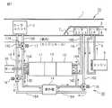
図1は、本発明に係る磁気ヒートポンプシステム30を用いた車両用の空気調和装置10の構成を示すものである。空気調和装置10は車両の室内側にあり、その装置本体1の中に吸熱手段としてのクーラユニット2がある。また、クーラユニット2の下流側には、冷房通路3と、熱輸送媒体が有する熱を外部へ放熱する放熱手段としてのヒータユニット5とヒータコア6を備える暖房通路4とがある。そして、冷房通路3と暖房通路4の入口部にはエアミックスダンパ7が設けられており、エアミックスダンパ7の移動によってクーラユニット2を通過した気流を冷房通路3に流すか、暖房通路4を流すかの調節が行われるようになっている。 FIG. 1 shows a configuration of a
一方、車両のエンジンルーム内には、モータ20によって駆動される回転軸21によって動作する冷却水製造部11、温水製造部12及び熱輸送媒体移動手段である往復動ポンプ13がある。往復動ポンプ13は熱輸送媒体を往復移動させる。冷却水製造部11、温水製造部12及び往復動ポンプ13の内部構造については後述する。冷却水製造部11は磁気の作用で熱輸送媒体を冷却するものであり、冷却水製造部11で冷却された熱輸送媒体は往復動ポンプ13によって冷却水循環路(第1の循環路)15に吐出され、クーラユニット2に送られた後に冷却水製造部11に戻ってくる。逆に、温水製造部12は磁気の作用で熱輸送媒体を加熱するものであり、温水製造部12で加熱された熱輸送媒体は往復動ポンプ13によって温水循環路(第2の循環路)16に吐出され、ヒータユニット5に送られた後に温水製造部12に戻ってくる。 On the other hand, in the engine room of the vehicle, there is a cooling
一方、空気調和装置10では、その暖房通路4に設けられたヒータコア6に、エンジン8を冷却して暖められた冷却水(クーラント)がクーラント循環路9を通じて供給され、ヒータユニット5と共に暖房通路4を通る気流を暖める。ヒータコア6は本発明には直接関係がないので、ヒータコア6についてはこれ以上の説明を省略する。 On the other hand, in the
ここで、冷却水循環路15と温水循環路16の構成について詳細に説明する。冷却水製造部11には複数のシリンダがあり、各シリンダには枝管15Aが接続されている。複数の枝管15Aは集合され、供給管15Bとなってクーラユニット2に熱輸送媒体を供給する。クーラユニット2から排出された熱輸送媒体は、戻り管15Cによって冷却水製造部11まで戻り、各シリンダに接続された枝管15Dに分配されて各シリンダに戻る。供給管15Bと戻り管15Cの間には、クーラユニット2をバイパスするバイパス管(第1のバイパス通路)17Aが設けられている。バイパス管17Aは、戻り管15Cには直接接続されるが、供給管15Bには第1の流路切換弁17を介して接続されている。 Here, the configuration of the cooling
暖房時には、第1の流路切換弁17の切り換えにより、供給管15Bを流れる熱輸送媒体は、クーラユニット2を経由せず、バイパス管17Aを経由して冷却水製造部11まで戻ることができる。更に、戻り管15Cの枝管15Dの上流側には、第3の流路切換弁19があり、第3の流路切換弁19には室外器14を経由して第3の戻り管15Cに戻る迂回管(第3のバイパス通路)19Aが接続されている。暖房時には、第3の流路切換弁19の切り換えにより、戻り管15Cを流れてきた熱輸送媒体は、第3の流路切換弁19から迂回管19Aに流れ、室外器14で外気から吸熱して迂回管19Aから戻り管15Cに再流入する。戻り管15Cに再流入した熱輸送媒体は冷却水製造部11に戻る。 During heating, by switching the first flow
同様に、温水製造部12には熱輸送媒体を加熱して温水にする複数のシリンダがあり、各シリンダには枝管16Aが接続されている。複数の枝管16Aは集合され、供給管16Bとなってヒータユニット5に熱輸送媒体を供給する。ヒータユニット5から排出された熱輸送媒体は、戻り管16Cによって温水製造部12まで戻り、前述の各シリンダに接続された枝管16Dに分配されて各シリンダに戻る。枝管16Dの上流側の戻り管16Cには、第2の流路切換弁18があり、第2の流路切換弁18には室外器14を経由して戻り管16Cに戻る迂回管(第2のバイパス通路)18Aが接続されている。第2の流路切換弁18の切り換えにより、戻り管16Cを流れてきた熱輸送媒体は、温水製造部12に戻る前に迂回管18Aに流れ、室外器14で外気から吸熱してから、温水製造部12に戻ることができる。 Similarly, the hot
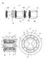
ここで、図2(a)、(b)、図3(a)〜(c)を用いて冷却水製造部11、温水製造部12及び往復動ポンプ13の内部構造について説明する。なお、図2(a)は往復動ポンプ13にラジアルピストンポンプを使用した実施例を示し、図2(b)は、往復動ポンプ13に斜板コンプレッサを使用した実施例を示している。往復動ポンプ13に対して左右逆に取り付けられる冷却水製造部11と温水製造部12の構造は同じであるので、同じ構成部材には同じ符号を付し、代表として、往復動ポンプ13がラジアルピストンポンプである場合の冷却水製造部11の構造について説明する。 Here, the internal structure of the cooling
冷却水製造部11は、回転軸21に対して同心円状に配置された円筒状のヨーク部24を備えており、回転軸21には図3(a)、(c)に示すような、断面が扇状のロータ22が対向して設けられている。そして、ロータ22の外周面には永久磁石23が設置されている。永久磁石23の一方は外側がN極であり、他方は外側がS極である。そして、永久磁石23の回転軌跡の外側とヨーク部24の内周面との間には、磁気熱量効果を有する磁気熱量効果材料26が充填された複数の材料容器25が配置される。磁気熱量効果材料26が充填された材料容器25は熱輸送媒体を流通させる。 The cooling
材料容器25は図3(b)に示すように、その外形が断面が扇紙型の筒状をしており、内部の空間にペレット状の磁気熱量効果材料26が充填され、両端部がメッシュ状の端板25Mで塞がれて、磁気熱量効果材料26を閉じ込めている。液体は材料容器25の一端から端板25Mを通って内部に進入し、磁気熱量効果材料26の間の隙間を通って反対側の端部から端板25Mを通って外部に抜け出ることができる。この実施例では、ヨーク部24の内周面に6個の同じ形状の材料容器25が配置されており、材料容器25の内周面側を、ロータ22の外周面に取り付けられた永久磁石23が回転移動する。ロータ22、永久磁石23及びヨーク部24が、材料容器25に充填された磁気熱量効果材料26に与える磁場の大きさを変更する磁場変更手段として機能する。 As shown in FIG. 3 (b), the
図2(a)に戻って説明を続けると、この実施例では往復動ポンプ13がラジアルピストンポンプで構成されており、ラジアルピストンポンプ13の本体は、冷却水製造部11及び温水製造部12のヨーク部24と一体的に形成されている。ラジアルピストンポンプ13には、冷却水製造部11にある材料容器25の個数に合わせて6つのシリンダ34が回転軸21に対して放射状に設けられており、各シリンダ34の内部には往復動するピストン33が設けられている。一方、モータ20によって回転する回転軸21には回転軸21に対して偏心している制御カム32Aが取り付けられており、制御カム32Aのカムプロファイル(輪郭)に各ピストン33が係合している。制御カム32Aが1回転すると、各シリンダ34内のピストン33が1往復する。回転軸21から遠い側の各シリンダ34の側面は、連絡通路38によって冷却水製造部11と温水製造部12の各材料容器25の端面に接続されている。 Returning to FIG. 2 (a), the description will be continued. In this embodiment, the
図2(a)に示す実施例では、ラジアルピストンポンプ13から遠い側の冷却水製造部11の端面には、端面板29が取り付けられている。端面板29には、各材料容器25の端面に熱輸送媒体を導き入れる吸入弁28と、各材料容器25の端面から排出される熱輸送媒体を吐出する吐出弁27とが設けられている。吐出弁27には図1で説明した冷却水循環路15の供給管15Bの枝管15Aが接続し、吸入弁28には図1で説明した冷却水循環路15の戻り管15Cの枝管15Dが接続する。以上、冷却水製造部11の構造を説明したが、往復動ポンプ13がラジアルピストンポンプの場合は、冷却水製造部11と温水製造部12における永久磁石23の回転軸21に対する位置は、90度ずれている。 In the embodiment shown in FIG. 2A, an
図2(b)に示す実施例では、往復動ポンプ13が斜板コンプレッサで構成されており、斜板コンプレッサ13は冷却水製造部11と温水製造部12とは別体となっている。斜板コンプレッサ13には、冷却水製造部11にある材料容器25の個数に合わせて6つのシリンダ34があり、各シリンダ34の内部には往復動するピストン33が設けられている。そして各ピストン33には、モータ20によって回転する回転子31に取り付けられた斜板32Bの外周部が係合している。斜板32Bは、回転子31に対して斜めに取り付けられており、回転子31が1回転すると、斜板32Bは各シリンダ34内のピストン33を1往復させる。各シリンダ34の冷却水製造部11側及び温水製造部12側の端面は、連絡管37を通る連絡通路38によって冷却水製造部11の各材料容器25の端面に接続されている。36はギヤである。 In the embodiment shown in FIG. 2B, the
前述のように、冷却水製造部11の構成と同様に構成された温水製造部12では、往復動ポンプ13と反対側の端面板29にある吐出弁27に、図1で説明した温水循環路16の供給管16Bの枝管16Aが接続し、吸入弁28には図1で説明した温水循環路16の戻り管16Cの枝管16Dが接続する。そして、往復動ポンプ13においてピストン33が動作し、冷却水製造部11のある材料容器25において熱輸送媒体が吸引されると、往復動ポンプ13がラジアルピストンポンプの場合には、対向する温水製造部12の対応する材料容器25において熱輸送媒体が同様に吸引されるが、往復動ポンプ13が斜板コンプレッサの場合には、対向する温水製造部12の対応する材料容器25において熱輸送媒体が逆に吐出される。 As described above, in the hot
冷却水製造部11側では、材料容器25から熱輸送媒体が吐出される時に、材料容器25内にある磁気熱量効果材料26に印加されていた磁場を除去することにより、磁気熱量効果材料26の温度が下がり、吐出される熱輸送媒体が冷却されて冷却水循環路15に送り込まれる。逆に、温水製造部12側では、材料容器25から熱輸送媒体が吐出される時に、材料容器25内にある磁気熱量効果材料26に磁場を印加することにより、磁気熱量効果材料26が発熱し、吐出される熱輸送媒体が加熱されて温水循環路16に送り込まれる。永久磁石23は、以上のような動作が行えるように、ロータ22に配置されている。 On the cooling
以上のように構成された磁気ヒートポンプシステム30及び磁気ヒートポンプシステム30を組み込んだ空気調和装置10において、本発明では熱輸送媒体中に熱輸送媒体より熱伝導率の高い物質を混入させる。熱輸送媒体より熱伝導率の高い物質としては、例えば、カーボンナノチューブ、グラフェン、アルミナ及び金粒子等がある。熱輸送媒体中に熱輸送媒体より熱伝導率の高い物質を混入させると、熱輸送媒体の熱伝達率が向上する。この結果、熱輸送媒体が材料容器25内を通過する時に、磁気熱量効果材料26との熱交換が良好に行われ、熱輸送媒体が短時間で冷却、或いは加熱される。これにより、同じ温度の熱輸送媒体で良い場合は、材料容器25を通過させる熱輸送媒体の速度を向上させることができ、冷間始動後の空気調和装置10の冷却機能、或いは暖房機能の立ち上がり時間を短くすることができる。また、材料容器25を通過させる熱輸送媒体の速度を同じにした場合は、材料容器25を通過した熱輸送媒体の温度低下、或いは温度上昇が大きく、空気調和装置10の冷却能力、或いは暖房能力を向上させることができる。 In the
ここで、熱輸送媒体中に熱輸送媒体より熱伝導率の高い物質を混入させた場合、特に、カーボンナノチューブを混入させた場合を考える。この場合、図4(a)に示すように、薄板状の材料26の間にある熱輸送媒体42に混入させたカーボンナノチューブ40が、両端が材料26の方向を向いた同じ方向に揃っている(配向されている)場合は、熱伝達率が向上する。一方、図4(b)に示すように、薄板状の材料26の間にある熱輸送媒体42に混入させたカーボンナノチューブ40が、両端が材料26に平行な同じ方向に揃ってしまった場合は、熱伝達率が向上しない。また、熱輸送媒体42に混入させたカーボンナノチューブ40が凝集してしまった場合も熱伝達率が向上しない。なお、凝集に関しては、カーボンナノチューブ以外の熱輸送媒体より熱伝導率の高い物質を熱輸送媒体中に混入させた場合でも、凝集が起こると熱伝導率が向上しない。 Here, a case where a substance having a higher thermal conductivity than the heat transport medium is mixed in the heat transport medium, particularly a case where carbon nanotubes are mixed is considered. In this case, as shown in FIG. 4A, the
そこで、熱輸送媒体42に混入させたカーボンナノチューブ40が、薄板状の材料26の間を通過する際には、図4(c)に示すように、カーボンナノチューブ40が凝集しておらず、その配向方向が一様でないようにする。カーボンナノチューブ40が凝集しておらず、その配向方向が一様でない場合は、熱輸送媒体42の熱伝達率が低下しない。このための第1の方法は、熱輸送媒体42の中にカーボンナノチューブ40を混入させると共に、熱輸送媒体42の中に、図4(d)に示すように微小な磁性体41を混入する方法である。また、カーボンナノチューブ40自体に磁性体、例えば鉄成分を配合することも可能である。 Therefore, when the
微小な磁性体41、或いは磁性体41を配合したカーボンナノチューブ40は、熱輸送媒体42が材料容器25内を通過する際に、材料容器25に印加される磁場の変化で流動する。カーボンナノチューブ40の流動によって、熱輸送媒体42の中のカーボンナノチューブ40の配向方向が乱れる。この結果、カーボンナノチューブ40を混入させた熱輸送媒体42が材料容器25を通過する際の熱輸送媒体42の熱伝達率が低下しない。 The minute magnetic body 41 or the
熱輸送媒体42に混入させたカーボンナノチューブ40を、材料容器25内で一様でないようにする第2の方法は、熱輸送媒体42を材料容器25内で強制的に掻き混ぜる方法である。このいくつかの実施例を図5から図10を用いて説明する。 A second method for making the
図5及び図6は第2の方法を実現する材料容器25の構成の第1の形態の撹拌構造50の構成を示すものである。第1の形態では、図5(a)に示すように、材料容器25の筐体内に磁場変化に追従して回転する撹拌子51を組み込んでいる。即ち、第1の形態では、材料容器25を第1の材料容器25Aと第2の材料容器25Bに分け、第1の材料容器25Aと第2の材料容器25Bの両端部に撹拌子51を組み込んでいる。撹拌子51は断面形状が第1の材料容器25Aと第2の材料容器25Bの断面形状と同じ枠体(回転空間形成枠)53の中に挿入し、枠体53の内側にある回転空間52で回転できるようにする。この形態では、第1の材料容器25Aと第2の材料容器25Bの外側に位置する枠体53の外側の端面には、図3(b)で説明したメッシュ状端板25Mと同様のメッシュ状端板25Mを取り付けているが、これは無くても良い。 5 and 6 show the configuration of the stirring
図5(b)は、往復動ポンプ13が斜板コンプレッサである場合の、図5(a)のように構成された撹拌構造50が組み込まれた冷却水製造部11の構成を示すものであり、図5(c)は図5(b)のB‐B線における断面図である。撹拌構造50に組み込まれた撹拌子51は枠体53の回転空間52で回転できるようになっており、その回転動作を図6(a)〜(f)を用いて説明する。撹拌子51は磁化しておき、N極とS極の極性を持たせておく。ここでは、1つの回転空間52内の撹拌子51の回転動作について説明する。 FIG. 5B shows a configuration of the cooling
1つの回転空間52内の撹拌子51として、図6(a)の左側の撹拌子51の回転について説明する。この撹拌子51を撹拌子51Aとする。図6(a)は1つの永久磁石23の外周面が横方向を向いており、永久磁石23のN極が撹拌子51Aの真横にある状態を示している。この状態では撹拌子51AのS極が永久磁石23のN極と引き合っており、撹拌子51Aは水平方向を向いている。 The rotation of the
図6(b)は図6(a)の状態からロータ22が60度、時計回りに回転した状態を示している。この状態では永久磁石23のN極が撹拌子51Aの右上方向に離れ、これに追従して撹拌子51AのS極が永久磁石23のN極がある方向に、半時計周りに回転する。図6(c)は図6(b)の状態からロータ22が60度、時計回りに回転した状態を示している。この状態では永久磁石23のN極が撹拌子51Aの右上方向に離れてゆき、代わりにもう1つの永久磁石23のS極が右下側から接近してくる。すると今度は撹拌子51のN極がこの永久磁石23のS極に引かれ、撹拌子51AのN極が永久磁石23のS極がある方向に、半時計周りに回転する。 FIG. 6B shows a state in which the
図6(d)は図6(c)の状態からロータ22が60度、時計回りに回転した状態を示しており、別の永久磁石23の外周面が横方向を向いた状態、即ち、永久磁石23のS極が撹拌子51Aの真横にある状態を示している。この状態では撹拌子51AのN極が永久磁石23のS極と引き合っており、撹拌子51Aは水平方向を向いている。図6(e)は図6(d)の状態からロータ22が60度、時計回りに回転した状態を示している。この状態では永久磁石23のS極が撹拌子51Aの右上方向に離れ、これに追従して撹拌子51AのN極が永久磁石23のS極がある方向に、半時計周りに回転する。 FIG. 6 (d) shows a state in which the
図6(f)は図6(e)の状態からロータ22が60度、時計回りに回転した状態を示している。この状態では永久磁石23のS極が撹拌子51Aの右上方向に離れてゆき、代わりに最初の永久磁石23のN極が右下側から接近してくる。すると今度は撹拌子51AのS極がこの永久磁石23のN極に引かれ、撹拌子51AのS極が永久磁石23のN極がある方向に、半時計周りに回転する。この状態からロータ22が更に60度時計回りに回転すると、図6(a)の状態に戻る。このように、撹拌子51Aはロータ22の回転に追従して回転し、ロータ22が時計回りに1回転すると、撹拌子51Aは半時計回りに1回転する。このように、撹拌子51がロータ22の回転によって回転するので、熱輸送媒体は撹拌子51によって撹拌されてから第1の材料容器25Aと第2の材料容器25Bに流入する。 FIG. 6F shows a state in which the
以上説明した第2の方法、即ち、熱輸送媒体42に混入させたカーボンナノチューブ40を熱輸送媒体42を材料容器25内で強制的に掻き混ぜて、材料容器25内で一様でないようにする方法は、カーボンナノチューブ以外の熱輸送媒体より熱伝導率の高い物質を熱輸送媒体中に混入させた場合にも適用することができる。 The second method described above, that is, the
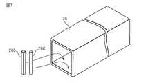
図7は本発明の磁気ヒートポンプシステム30における第2の形態の材料容器25の撹拌構造を説明するものである。なお、第2の形態では、説明を分かりやすくするために、材料容器25の形状を直方体状としているが、材料容器25の形状は第1の形態と同じにすることも可能である。そして、第2の形態では、材料容器25の中にペレット状ではなく、円柱状の磁気熱量効果材料26C、或いは角柱状の磁気熱量効果材料26Sを配置して熱輸送媒体を撹拌するようになっている。 FIG. 7 explains the stirring structure of the
図8(a)〜(c)は本発明の磁気ヒートポンプシステム30における第2の形態の第1の実施例の材料容器25の撹拌構造を示している。第1の実施例では、円柱状の磁気熱量効果材料26Cを、材料容器25の一方の開口端から他方の開口端に向かって一直線状に複数列並べている。円柱状の磁気熱量効果材料26Cをこのように配置すると、材料容器25内に吸い込まれた熱輸送媒体、或いは材料容器25から排出される熱輸送媒体は、図に太線で示すように、一列に並んだ円柱状の磁気熱量効果材料26Cの隙間の空間をジグザグ状に流れる。この結果、材料容器25で熱輸送媒体が撹拌される。 FIGS. 8A to 8C show the stirring structure of the
図9(a)、(b)は本発明の磁気ヒートポンプシステム30における第2の形態の第2の実施例の材料容器25の撹拌構造を示している。第2の実施例では、円柱状の磁気熱量効果材料26Cを、材料容器25の一方の開口端から他方の開口端に向かって、所定本数ずつジグザグ状に並べたものを複数個配置している。円柱状の磁気熱量効果材料26Cをこのように配置すると、材料容器25内に吸い込まれた熱輸送媒体、或いは材料容器25から排出される熱輸送媒体は、図に太線で示すように、ジグザグ状に並んだ円柱状の磁気熱量効果材料26Cの集合体同士の隙間の空間を大きく蛇行して流れる。この結果、材料容器25で熱輸送媒体が撹拌される。 FIGS. 9A and 9B show the stirring structure of the
図9(c)、(d)は本発明の磁気ヒートポンプシステム30における第2の形態の第3の実施例の材料容器25の撹拌構造を示している。第3の実施例では、角柱状の磁気熱量効果材料26Sを、材料容器25の一方の開口端から他方の開口端に向かって一直線状に複数列並べている。角柱状の磁気熱量効果材料26Sをこのように配置すると、材料容器25内に吸い込まれた熱輸送媒体、或いは材料容器25から排出される熱輸送媒体は、図に太線で示すように、一列に並んだ角柱状の磁気熱量効果材料26Sの隙間の空間をジグザグ状に流れる。この結果、材料容器25で熱輸送媒体が撹拌される。第1の実施例の円柱状の磁気熱量効果材料26Cを配置した場合に比べて、角柱状の磁気熱量効果材料26Sには角があるので、熱輸送媒体が角柱状の磁気熱量効果材料26Sに当たった時の乱れが大きく、ジグザグの程度が大きい。 FIGS. 9C and 9D show the stirring structure of the
図10(a)は本発明の磁気ヒートポンプシステム30における第2の形態の第4の実施例の材料容器25の撹拌構造を示している。第4の実施例では、円柱状の磁気熱量効果材料26Cを、材料容器25の一方の開口端から他方の開口端に向かって、垂直方向に一直線状に複数列、複数個だけ並べた後、今度は水平方向に一直線状に複数列、複数個だけ並べ、以後はこの並べ方を繰り返す。第1から第3の実施例では、材料容器25内に吸い込まれた熱輸送媒体、或いは材料容器25から排出される熱輸送媒体は、円柱状の磁気熱量効果材料26Cの隙間の空間を水平方向に蛇行して流れるだけであった。一方、第4の実施例の材料容器25の撹拌構造では、材料容器25内に吸い込まれた熱輸送媒体、或いは材料容器25から排出される熱輸送媒体は、水平方向に蛇行させられた後に垂直方向にも蛇行させられる。よって、材料容器25内での熱輸送媒体の撹拌の程度が強まる。 FIG. 10A shows the stirring structure of the
図10(b)は本発明の磁気ヒートポンプシステム30における第2の形態の第5の実施例の材料容器25の撹拌構造を示している。第5の実施例では、第4の実施例における円柱状の磁気熱量効果材料26Cを、角柱状の磁気熱量効果材料26Sに代えている。第5の実施例の材料容器25の撹拌構造でも、材料容器25内に吸い込まれた熱輸送媒体、或いは材料容器25から排出される熱輸送媒体は、水平方向に蛇行させられた後に垂直方向にも蛇行させられる。しかも、円柱状の磁気熱量効果材料26Cの代わりに角柱状の磁気熱量効果材料26Sを使用しているので、材料容器25内での熱輸送媒体の撹拌の程度が一層強まる。 FIG.10 (b) has shown the stirring structure of the
図8から図10に示した第1から第5の実施例の円柱状の磁気熱量効果材料26C、或いは角柱状の磁気熱量効果材料26Sの材料容器25内への配置は一例であり、配置はこれらの実施例に限定されるものではない。円柱状の磁気熱量効果材料26C、或いは角柱状の磁気熱量効果材料26Sの配置により、材料容器25内で熱輸送媒体を回転させることも可能である。 The arrangement of the cylindrical
以上説明した実施例では、磁気ヒートポンプシステムに使用する熱輸送媒体42の中に熱輸送媒体42より熱伝導率の高い物質40を混入させ、磁気熱量効果材料26との熱伝達率を向上させている。一方、熱輸送媒体42より熱伝導率の高い物質40の代わりに、熱輸送媒体42の中に熱輸送媒体42より比熱もしくは容積比熱の高い物質40を混入させ、磁気熱量効果材料26との熱伝達率を向上させることが可能である。 In the embodiment described above, the
熱輸送媒体42より比熱もしくは容積比熱の高い物質40としては、潜熱蓄熱材料を使用することができる。具体的には、潜熱蓄熱材料として、パラフィン、エリスリトール、スレイトール、ナフタリン、ポリエチレン及びステアリン酸の何れかを使用することが可能である。潜熱蓄熱材料も熱輸送媒体42に混入させると、カーボンナノチューブ40と同様に凝集する問題があるので、熱伝達率の向上のために撹拌が有効である。従って、熱輸送媒体42の中に熱輸送媒体42より比熱もしくは容積比熱の高い物質40を混入させた場合の磁気ヒートポンプシステム及び磁気ヒートポンプシステムを使用した空気調和装置の実施例は、前述の実施例と同じで良い。よって、ここではその説明を省略する。 A latent heat storage material can be used as the
2 吸熱手段(クーラユニット)
5 放熱手段(ヒータユニット)
10 空気調和装置
11 冷却水製造部
12 温水製造部
13 熱輸送媒体移動手段(往復動ポンプ、斜板コンプレッサ)
14 室外器
15 冷却水循環路
16 温水循環路
17,18,19 流路切換弁
21 回転軸
22 ロータ
23 永久磁石
24 ヨーク部
25 材料容器
26,26C,26S 磁気熱量効果材料
27 吐出弁
28 吸入弁
30 本発明の磁気ヒートポンプシステム
31 回転子
32A 制御カム
32B 斜板
33 ピストン
34 シリンダ
40 熱輸送媒体より熱伝導率の高い物質
41 微小な磁性体
50 撹拌構造
51 撹拌子2 Heat absorption means (cooler unit)
5 Heat dissipation means (heater unit)
DESCRIPTION OF
DESCRIPTION OF
Claims (15)
Translated fromJapanese前記磁気熱量効果材料(26)へ印加する磁場の大きさを変更する磁場変更手段(22)と、
前記磁気熱量効果材料(26)が内部に配置された前記容器(25)の両端部の間で、前記熱輸送媒体(42)を往復移動させる熱輸送媒体移動手段(13)と、
前記容器(25)の一方の端部側から排出された前記熱輸送媒体(42)が有する熱を外部へ放熱する放熱手段(5)と、
前記容器(25)の他方の端部側から排出された前記熱輸送媒体(42)に対して外部の熱を吸熱する吸熱手段(2)と、を備える磁気ヒートポンプシステムにおいて、
前記熱輸送媒体(42)中に前記熱輸送媒体(42)より熱伝導率の高い物質(40)と微小な磁性体(41)を混入させたことを特徴とする磁気ヒートポンプシステム。A magneto-caloric effect material (26) having a magneto-caloric effect is disposed inside, and a container (25) formed so that a heat transport medium (42) flows therethrough;
Magnetic field changing means (22) for changing the magnitude of the magnetic field applied to the magnetocaloric effect material (26);
Heat transport medium moving means (13) for reciprocating the heat transport medium (42) between both ends of the container (25) in which the magnetocaloric effect material (26) is disposed;
Heat radiating means (5) for radiating the heat of the heat transport medium (42) discharged from one end side of the container (25) to the outside;
In a magnetic heat pump system comprising: heat absorption means (2) that absorbs external heat to the heat transport medium (42) discharged from the other end side of the container (25),
A magnetic heat pump system, wherein a substance (40) having a higher thermal conductivity than the heat transport medium (42)and a minute magnetic body (41) are mixed in the heat transport medium (42).
前記磁気熱量効果材料(26)へ印加する磁場の大きさを変更する磁場変更手段(22)と、
前記磁気熱量効果材料(26)が内部に配置された前記容器(25)の両端部の間で、前記熱輸送媒体(42)を往復移動させる熱輸送媒体移動手段(13)と、
前記容器(25)の一方の端部側から排出された前記熱輸送媒体(42)が有する熱を外部へ放熱する放熱手段(5)と、
前記容器(25)の他方の端部側から排出された前記熱輸送媒体(42)に対して外部の熱を吸熱する吸熱手段(2)と、を備える磁気ヒートポンプシステムにおいて、
前記熱輸送媒体(42)中に前記熱輸送媒体(42)より比熱もしくは容積比熱の高い物質(40)と微小な磁性体(41)を混入させたことを特徴とする磁気ヒートポンプシステム。A magneto-caloric effect material (26) having a magneto-caloric effect is disposed inside, and a container (25) formed so that a heat transport medium (42) flows therethrough;
Magnetic field changing means (22) for changing the magnitude of the magnetic field applied to the magnetocaloric effect material (26);
Heat transport medium moving means (13) for reciprocating the heat transport medium (42) between both ends of the container (25) in which the magnetocaloric effect material (26) is disposed;
Heat radiating means (5) for radiating the heat of the heat transport medium (42) discharged from one end side of the container (25) to the outside;
In a magnetic heat pump system comprising: heat absorption means (2) that absorbs external heat to the heat transport medium (42) discharged from the other end side of the container (25),
A magnetic heat pump system, wherein a substance (40) having a specific heat or volume specific heat higher than that of the heat transport medium (42)and a minute magnetic body (41) are mixed in the heat transport medium (42).
前記磁気熱量効果材料(26)へ印加する磁場の大きさを変更する磁場変更手段(22)と、
前記磁気熱量効果材料(26)が内部に配置された前記容器(25)の両端部の間で、前記熱輸送媒体(42)を往復移動させる熱輸送媒体移動手段(13)と、
前記容器(25)の一方の端部側から排出された前記熱輸送媒体(42)が有する熱を外部へ放熱する放熱手段(5)と、
前記容器(25)の他方の端部側から排出された前記熱輸送媒体(42)に対して外部の熱を吸熱する吸熱手段(2)と、を備える磁気ヒートポンプシステムにおいて、
前記熱輸送媒体(42)中に前記熱輸送媒体(42)より熱伝導率の高い物質(40)を混入させ、前記熱伝導率の高い物質(40)自体に磁性体を配合したことを特徴とする磁気ヒートポンプシステム。A magneto-caloric effect material (26) having a magneto-caloric effect is disposed inside, and a container (25) formed so that a heat transport medium (42) flows therethrough;
Magnetic field changing means (22) for changing the magnitude of the magnetic field applied to the magnetocaloric effect material (26);
Heat transport medium moving means (13) for reciprocating the heat transport medium (42) between both ends of the container (25) in which the magnetocaloric effect material (26) is disposed;
Heat radiating means (5) for radiating the heat of the heat transport medium (42) discharged from one end side of the container (25) to the outside;
In a magnetic heat pump system comprising: heat absorption means (2) that absorbs external heat to the heat transport medium (42) discharged from the other end side of the container (25),
A substance (40) having a higher thermal conductivity than the heat transport medium (42) is mixed in the heat transport medium (42), and a magnetic substance is blended in the substance (40) having a higher heat conductivity. And magnetic heat pump system.
前記磁気熱量効果材料(26)へ印加する磁場の大きさを変更する磁場変更手段(22)と、
前記磁気熱量効果材料(26)が内部に配置された前記容器(25)の両端部の間で、前記熱輸送媒体(42)を往復移動させる熱輸送媒体移動手段(13)と、
前記容器(25)の一方の端部側から排出された前記熱輸送媒体(42)が有する熱を外部へ放熱する放熱手段(5)と、
前記容器(25)の他方の端部側から排出された前記熱輸送媒体(42)に対して外部の熱を吸熱する吸熱手段(2)と、を備える磁気ヒートポンプシステムにおいて、
前記熱輸送媒体(42)中に前記熱輸送媒体(42)より比熱もしくは容積比熱の高い物質(40)を混入させ、前記媒体より比熱もしくは容積比熱の高い物質(40)自体に磁性体を配合したことを特徴とする磁気ヒートポンプシステム。A magneto-caloric effect material (26) having a magneto-caloric effect is disposed inside, and a container (25) formed so that a heat transport medium (42) flows therethrough;
Magnetic field changing means (22) for changing the magnitude of the magnetic field applied to the magnetocaloric effect material (26);
Heat transport medium moving means (13) for reciprocating the heat transport medium (42) between both ends of the container (25) in which the magnetocaloric effect material (26) is disposed;
Heat radiating means (5) for radiating the heat of the heat transport medium (42) discharged from one end side of the container (25) to the outside;
In a magnetic heat pump system comprising: heat absorption means (2) that absorbs external heat to the heat transport medium (42) discharged from the other end side of the container (25),
A substance (40) having a specific heat or volume specific heat higher than that of the heat transport medium (42) is mixed in the heat transport medium (42), and a magnetic substance is blended in the substance (40) itself having a specific heat or volume specific heat higher than that of the medium. Magnetic heat pump systemcharacterized by that .
前記磁気熱量効果材料(26)へ印加する磁場の大きさを変更する磁場変更手段(22)と、
前記磁気熱量効果材料(26)が内部に配置された前記容器(25)の両端部の間で、前記熱輸送媒体(42)を往復移動させる熱輸送媒体移動手段(13)と、
前記容器(25)の一方の端部側から排出された前記熱輸送媒体(42)が有する熱を外部へ放熱する放熱手段(5)と、
前記容器(25)の他方の端部側から排出された前記熱輸送媒体(42)に対して外部の熱を吸熱する吸熱手段(2)と、を備える磁気ヒートポンプシステムにおいて、
前記熱輸送媒体(42)中に前記熱輸送媒体(42)より熱伝導率の高い物質(40)を混入させ、
前記熱輸送媒体(42)より熱伝導率の高い物質(40)が、カーボンナノチューブ、グラフェン、アルミナ及び金粒子の何れかであり、
前記媒体より熱伝導率の高い物質(40)自体に磁性体を配合したことを特徴とする磁気ヒートポンプシステム。A magneto-caloric effect material (26) having a magneto-caloric effect is disposed inside, and a container (25) formed so that a heat transport medium (42) flows therethrough;
Magnetic field changing means (22) for changing the magnitude of the magnetic field applied to the magnetocaloric effect material (26);
Heat transport medium moving means (13) for reciprocating the heat transport medium (42) between both ends of the container (25) in which the magnetocaloric effect material (26) is disposed;
Heat radiating means (5) for radiating the heat of the heat transport medium (42) discharged from one end side of the container (25) to the outside;
In a magnetic heat pump system comprising: heat absorption means (2) that absorbs external heat to the heat transport medium (42) discharged from the other end side of the container (25),
A substance (40) having higher thermal conductivity than the heat transport medium (42) is mixed in the heat transport medium (42);
The substance (40) having a higher thermal conductivity than the heat transport medium (42) is any one of carbon nanotubes, graphene, alumina, and gold particles,
A magnetic heat pump systemcomprising a substance (40) having a higher thermal conductivity than the medium and a magnetic material .
前記磁気熱量効果材料(26)へ印加する磁場の大きさを変更する磁場変更手段(22)と、
前記磁気熱量効果材料(26)が内部に配置された前記容器(25)の両端部の間で、前記熱輸送媒体(42)を往復移動させる熱輸送媒体移動手段(13)と、
前記容器(25)の一方の端部側から排出された前記熱輸送媒体(42)が有する熱を外部へ放熱する放熱手段(5)と、
前記容器(25)の他方の端部側から排出された前記熱輸送媒体(42)に対して外部の熱を吸熱する吸熱手段(2)と、を備える磁気ヒートポンプシステムにおいて、
前記熱輸送媒体(42)中に前記熱輸送媒体(42)より比熱もしくは容積比熱の高い物質(40)を混入させ、
前記熱輸送媒体(42)より比熱もしくは容積比熱の高い物質(40)が、潜熱蓄熱材料であり、
前記媒体より比熱もしくは容積比熱の高い物質(40)自体に磁性体を配合したことを特徴とする磁気ヒートポンプシステム。A magneto-caloric effect material (26) having a magneto-caloric effect is disposed inside, and a container (25) formed so that a heat transport medium (42) flows therethrough;
Magnetic field changing means (22) for changing the magnitude of the magnetic field applied to the magnetocaloric effect material (26);
Heat transport medium moving means (13) for reciprocating the heat transport medium (42) between both ends of the container (25) in which the magnetocaloric effect material (26) is disposed;
Heat radiating means (5) for radiating the heat of the heat transport medium (42) discharged from one end side of the container (25) to the outside;
In a magnetic heat pump system comprising: heat absorption means (2) that absorbs external heat to the heat transport medium (42) discharged from the other end side of the container (25),
A substance (40) having a specific heat or a volume specific heat higher than that of the heat transport medium (42) is mixed in the heat transport medium (42),
The substance (40) having a specific heat or volume specific heat higher than that of the heat transport medium (42) is a latent heat storage material,
A magnetic heat pump systemcomprising a substance (40) having a specific heat or volume specific heat higher than that of the medium and a magnetic material .
前記熱輸送媒体移動手段(13)は、モータ(20)に駆動される回転軸(21)により駆動され、前記回転軸(21)の周囲に備えられた複数のシリンダから前記熱輸送媒体移動手段(13)の両側にある前記容器(25)に熱輸送媒体(42)を吐出、或いは前記容器(25)から熱輸送媒体を吸引するように構成され、
磁場変更手段(22,23)は、前記回転軸(21)に取り付けられたロータ(22)の外周面に設置された永久磁石(23)により構成され、
前記容器(25)に接続する循環路(15,16)は、前記吸熱手段(2)を備えた第1の循環路(15)と前記放熱手段(5)を備えた第2の循環路(16)から構成され、
前記第1の循環路(15)では、熱輸送媒体(42)の前記容器(25)からの吐出時に前記永久磁石(23)が前記磁気熱量効果材料(26)への磁場を除去するように動作し、前記第2の循環路(16)では、熱輸送媒体(42)の前記容器(25)からの吐出時に前記永久磁石(23)が前記磁気熱量効果材料(26)に磁場を印加するように動作し、
前記第1の循環路(15)には、前記容器(25)から吐出された冷却された熱輸送媒体(42)を前記吸熱手段(2)を通さずに前記容器(25)に戻すための第1のバイパス通路(17A)が設けられており、
前記第2の循環路(16)には、前記容器(25)に戻る前に外気から吸熱を行う室外器(14)を備えた第2のバイパス通路(18A)が設けられていて、
前記空気調和装置(10)の暖房時に、前記第1の循環路(15)の熱輸送媒体(42)は、前記第1のバイパス通路(17A)を通り、
前記空気調和装置(10)の冷房時に、前記第2の循環路(16)の熱輸送媒体(42)は、前記第2のバイパス通路(18A)を通ることを特徴とする空気調和装置。A magnetocaloric effect material (26) having a magnetocaloric effect is disposed inside, and a container (25) formed so that a heat transport medium (42) flows therethrough, and the magnetocaloric effect material (26 ) Between the both ends of the magnetic field changing means (22) for changing the magnitude of the magnetic field applied to the container (25) in which the magnetocaloric effect material (26) is disposed. 42) a heat transport medium moving means (13) for reciprocating movement, and a heat radiation means (5) for radiating the heat of the heat transport medium (42) discharged from one end side of the container (25) to the outside. ) And heat absorption means (2) that absorbs external heat to the heat transport medium (42) discharged from the other end of the container (25). In the transport medium (42) Amedium (42) air conditioner using amagnetic heat pump system (30) of high thermal conductivity material (40) was mixed from (10),
The heat transport medium moving means (13) is driven by a rotating shaft (21) driven by a motor (20), and the heat transport medium moving means from a plurality of cylinders provided around the rotating shaft (21). The heat transport medium (42) is discharged into the container (25) on both sides of (13), or the heat transport medium is sucked from the container (25).
The magnetic field changing means (22, 23) is composed of a permanent magnet (23) installed on the outer peripheral surface of the rotor (22) attached to the rotating shaft (21).
The circulation path (15, 16) connected to the container (25) includes a first circulation path (15) provided with the heat absorption means (2) and a second circulation path provided with the heat dissipation means (5) ( 16),
In the first circulation path (15), the permanent magnet (23) removes the magnetic field to the magnetocaloric effect material (26) when the heat transport medium (42) is discharged from the container (25). In operation, in the second circuit (16), the permanent magnet (23) applies a magnetic field to the magnetocaloric effect material (26) when the heat transport medium (42) is discharged from the container (25).works like,
In the first circulation path (15), the cooled heat transport medium (42) discharged from the container (25) is returned to the container (25) without passing through the heat absorption means (2). A first bypass passage (17A) is provided;
The second circulation path (16) is provided with a second bypass passage (18A) including an outdoor unit (14) that absorbs heat from outside air before returning to the container (25).
During heating of the air conditioner (10), the heat transport medium (42) of the first circulation path (15) passes through the first bypass passage (17A),
Wherein during the cooling of the air conditioner (10), the second heat transporting medium circulation path (16) (42), the air conditionercharacterized in that through the second bypass passage (18A).
前記磁気熱量効果材料(26)へ印加する磁場の大きさを変更する磁場変更手段(22)と、
前記磁気熱量効果材料(26)が内部に配置された前記容器(25)の両端部の間で、前記熱輸送媒体(42)を往復移動させる熱輸送媒体移動手段(13)と、
前記容器(25)の一方の端部側から排出された前記熱輸送媒体(42)が有する熱を外部へ放熱する放熱手段(5)と、
前記容器(25)の他方の端部側から排出された前記熱輸送媒体(42)に対して外部の熱を吸熱する吸熱手段(2)と、を備える磁気ヒートポンプシステムにおいて、
前記容器(25)内に、前記磁場変更手段(22)の磁場により駆動され、前記熱輸送媒体(42)を撹拌する撹拌構造(50)を設けたことを特徴とする磁気ヒートポンプシステム。A magneto-caloric effect material (26) having a magneto-caloric effect is disposed inside, and a container (25) formed so that a heat transport medium (42) flows therethrough;
Magnetic field changing means (22) for changing the magnitude of the magnetic field applied to the magnetocaloric effect material (26);
Heat transport medium moving means (13) for reciprocating the heat transport medium (42) between both ends of the container (25) in which the magnetocaloric effect material (26) is disposed;
Heat radiating means (5) for radiating the heat of the heat transport medium (42) discharged from one end side of the container (25) to the outside;
In a magnetic heat pump system comprising: heat absorption means (2) that absorbs external heat to the heat transport medium (42) discharged from the other end side of the container (25),
A magnetic heat pump system comprising a stirring structure (50) that isdriven by the magnetic field of the magnetic field changing means (22 ) and stirs the heat transport medium (42) in the container (25).
前記磁気熱量効果材料(26)へ印加する磁場の大きさを変更する磁場変更手段(22)と、
前記磁気熱量効果材料(26)が内部に配置された前記容器(25)の両端部の間で、前記熱輸送媒体(42)を往復移動させる熱輸送媒体移動手段(13)と、
前記容器(25)の一方の端部側から排出された前記熱輸送媒体(42)が有する熱を外部へ放熱する放熱手段(5)と、
前記容器(25)の他方の端部側から排出された前記熱輸送媒体(42)に対して外部の熱を吸熱する吸熱手段(2)と、を備える磁気ヒートポンプシステムにおいて、
前記熱輸送媒体(42)中に前記熱輸送媒体(42)より熱伝導率の高い物質(40)を混入させ、
前記容器(25)内に、熱輸送媒体(42)を撹拌する撹拌構造(50)を設け、
前記撹拌構造(50)が、前記磁気熱量効果材料(26)の前記容器(25)内への配置であり、前記磁気熱量効果材料(26)を柱状に形成し、前記熱輸送媒体(42)の流れ方向に複数の柱状の前記磁気熱量効果材料(26)を、前記磁気熱量効果材料(26)の間を流れる熱輸送媒体(42)の流れが乱れるように配置したことを特徴とする磁気ヒートポンプシステム。A magneto-caloric effect material (26) having a magneto-caloric effect is disposed inside, and a container (25) formed so that a heat transport medium (42) flows therethrough;
Magnetic field changing means (22) for changing the magnitude of the magnetic field applied to the magnetocaloric effect material (26);
Heat transport medium moving means (13) for reciprocating the heat transport medium (42) between both ends of the container (25) in which the magnetocaloric effect material (26) is disposed;
Heat radiating means (5) for radiating the heat of the heat transport medium (42) discharged from one end side of the container (25) to the outside;
In a magnetic heat pump system comprising: heat absorption means (2) that absorbs external heat to the heat transport medium (42) discharged from the other end side of the container (25),
A substance (40) having higher thermal conductivity than the heat transport medium (42) is mixed in the heat transport medium (42);
A stirring structure (50) for stirring the heat transport medium (42) is provided in the container (25),
The stirring structure (50) is an arrangement of the magnetocaloric effect material (26) in the container (25), the magnetocaloric effect material (26) is formed in a columnar shape, and the heat transport medium (42) A plurality of columnar magnetocaloric effect materials (26) are arranged in the flow direction so that the flow of the heat transport medium (42) flowing between the magnetocaloric effect materials (26) is disturbed. Heat pump system.
Priority Applications (5)
| Application Number | Priority Date | Filing Date | Title |
|---|---|---|---|
| JP2011274527AJP5338889B2 (en) | 2011-04-28 | 2011-12-15 | Magnetic heat pump system and air conditioner using the system |
| DE102012206359.5ADE102012206359B4 (en) | 2011-04-28 | 2012-04-18 | Magnetic heat pump system |
| FR1201182AFR2974621B1 (en) | 2011-04-28 | 2012-04-20 | MAGNETIC HEAT PUMP SYSTEM |
| CN201210120871.8ACN102759216B (en) | 2011-04-28 | 2012-04-23 | Magnetic heat pump system |
| US13/455,432US9534815B2 (en) | 2011-04-28 | 2012-04-25 | Magnetic heat pump with agitating structure and additives for heat transfer medium |
Applications Claiming Priority (3)
| Application Number | Priority Date | Filing Date | Title |
|---|---|---|---|
| JP2011102067 | 2011-04-28 | ||
| JP2011102067 | 2011-04-28 | ||
| JP2011274527AJP5338889B2 (en) | 2011-04-28 | 2011-12-15 | Magnetic heat pump system and air conditioner using the system |
Publications (2)
| Publication Number | Publication Date |
|---|---|
| JP2012237544A JP2012237544A (en) | 2012-12-06 |
| JP5338889B2true JP5338889B2 (en) | 2013-11-13 |
Family
ID=47007871
Family Applications (1)
| Application Number | Title | Priority Date | Filing Date |
|---|---|---|---|
| JP2011274527AExpired - Fee RelatedJP5338889B2 (en) | 2011-04-28 | 2011-12-15 | Magnetic heat pump system and air conditioner using the system |
Country Status (5)
| Country | Link |
|---|---|
| US (1) | US9534815B2 (en) |
| JP (1) | JP5338889B2 (en) |
| CN (1) | CN102759216B (en) |
| DE (1) | DE102012206359B4 (en) |
| FR (1) | FR2974621B1 (en) |
Cited By (1)
| Publication number | Priority date | Publication date | Assignee | Title |
|---|---|---|---|---|
| JP2012237497A (en)* | 2011-05-11 | 2012-12-06 | Denso Corp | Magnetic refrigeration system and air conditioner using the magnetic refrigeration system |
Families Citing this family (83)
| Publication number | Priority date | Publication date | Assignee | Title |
|---|---|---|---|---|
| US8769966B2 (en)* | 2010-08-09 | 2014-07-08 | Cooltech Applications Societe Par Actions Simplifiee | Thermal generator using magnetocaloric material |
| JP6000814B2 (en) | 2012-11-13 | 2016-10-05 | 株式会社東芝 | Magnetic refrigeration device and magnetic refrigeration system |
| US10465951B2 (en) | 2013-01-10 | 2019-11-05 | Haier Us Appliance Solutions, Inc. | Magneto caloric heat pump with variable magnetization |
| US9625185B2 (en) | 2013-04-16 | 2017-04-18 | Haier Us Appliance Solutions, Inc. | Heat pump with magneto caloric materials and variable magnetic field strength |
| US10126025B2 (en) | 2013-08-02 | 2018-11-13 | Haier Us Appliance Solutions, Inc. | Magneto caloric assemblies |
| KR101938717B1 (en)* | 2014-03-18 | 2019-01-16 | 삼성전자주식회사 | Magnetic regenerator unit and magnetic cooling system with the same |
| CN105020926B (en)* | 2014-04-21 | 2017-09-29 | 青岛海尔股份有限公司 | Magnetic refrigeration part and magnetic refrigeration apparatus |
| US9851128B2 (en) | 2014-04-22 | 2017-12-26 | Haier Us Appliance Solutions, Inc. | Magneto caloric heat pump |
| CN105020929B (en)* | 2014-04-24 | 2019-06-21 | 青岛海尔股份有限公司 | Slider type magnetic refrigeration components and magnetic refrigeration equipment |
| CN105020930B (en)* | 2014-04-30 | 2019-06-21 | 青岛海尔股份有限公司 | Rotary magnetic refrigeration device and magnetic refrigeration equipment |
| CN105020931B (en)* | 2014-04-30 | 2019-06-21 | 青岛海尔股份有限公司 | Rotary magnetic refrigeration mechanism and magnetic refrigeration equipment |
| CN105318595B (en)* | 2014-05-27 | 2019-06-21 | 青岛海尔股份有限公司 | Magnetic refrigeration components and magnetic refrigeration equipment |
| CN105222391B (en)* | 2014-05-27 | 2019-07-12 | 青岛海尔股份有限公司 | Reciprocating magnetic refrigeration part and magnetic refrigeration apparatus |
| US9797630B2 (en) | 2014-06-17 | 2017-10-24 | Haier Us Appliance Solutions, Inc. | Heat pump with restorative operation for magneto caloric material |
| CN105466070B (en)* | 2014-08-27 | 2019-06-21 | 青岛海尔股份有限公司 | Rotary magnetic refrigeration components and magnetic refrigeration equipment |
| CN105466071B (en)* | 2014-08-28 | 2019-06-21 | 青岛海尔股份有限公司 | Rotary multi-stage magnetic refrigeration components and magnetic refrigeration equipment |
| CN104357021A (en)* | 2014-10-22 | 2015-02-18 | 王子韩 | Graphene/paraffin composite phase change energy storage material and preparation method thereof |
| US10254020B2 (en) | 2015-01-22 | 2019-04-09 | Haier Us Appliance Solutions, Inc. | Regenerator including magneto caloric material with channels for the flow of heat transfer fluid |
| US9631843B2 (en) | 2015-02-13 | 2017-04-25 | Haier Us Appliance Solutions, Inc. | Magnetic device for magneto caloric heat pump regenerator |
| JP7218988B2 (en) | 2015-06-19 | 2023-02-07 | マグネート ベー.フェー. | Pack screen type magnetocaloric element |
| CN105222393A (en)* | 2015-10-24 | 2016-01-06 | 唐玉敏 | A kind of refrigerator type water heater cold-hot integrated device |
| CN105588246B (en)* | 2016-03-03 | 2018-05-18 | 郭振 | A kind of heat superconducting fan for increasing substantially air-conditioning heat-exchange capacity |
| JP2017154236A (en)* | 2016-03-04 | 2017-09-07 | 株式会社フジクラ | Manufacturing method of heat exchanger |
| JP6589706B2 (en)* | 2016-03-18 | 2019-10-16 | 株式会社デンソー | Thermomagnetic cycle equipment |
| EP3438568A4 (en)* | 2016-03-31 | 2020-02-12 | Fujikura Ltd. | Heat exchanger and magnetic heat pump device |
| US10299655B2 (en) | 2016-05-16 | 2019-05-28 | General Electric Company | Caloric heat pump dishwasher appliance |
| US10006674B2 (en) | 2016-07-19 | 2018-06-26 | Haier Us Appliance Solutions, Inc. | Linearly-actuated magnetocaloric heat pump |
| US9869493B1 (en) | 2016-07-19 | 2018-01-16 | Haier Us Appliance Solutions, Inc. | Linearly-actuated magnetocaloric heat pump |
| US10006672B2 (en) | 2016-07-19 | 2018-06-26 | Haier Us Appliance Solutions, Inc. | Linearly-actuated magnetocaloric heat pump |
| US10222101B2 (en) | 2016-07-19 | 2019-03-05 | Haier Us Appliance Solutions, Inc. | Linearly-actuated magnetocaloric heat pump |
| US10047979B2 (en) | 2016-07-19 | 2018-08-14 | Haier Us Appliance Solutions, Inc. | Linearly-actuated magnetocaloric heat pump |
| US9915448B2 (en) | 2016-07-19 | 2018-03-13 | Haier Us Appliance Solutions, Inc. | Linearly-actuated magnetocaloric heat pump |
| US10295227B2 (en)* | 2016-07-19 | 2019-05-21 | Haier Us Appliance Solutions, Inc. | Caloric heat pump system |
| US10006675B2 (en) | 2016-07-19 | 2018-06-26 | Haier Us Appliance Solutions, Inc. | Linearly-actuated magnetocaloric heat pump |
| US10274231B2 (en) | 2016-07-19 | 2019-04-30 | Haier Us Appliance Solutions, Inc. | Caloric heat pump system |
| US10047980B2 (en) | 2016-07-19 | 2018-08-14 | Haier Us Appliance Solutions, Inc. | Linearly-actuated magnetocaloric heat pump |
| US10281177B2 (en) | 2016-07-19 | 2019-05-07 | Haier Us Appliance Solutions, Inc. | Caloric heat pump system |
| US10006673B2 (en) | 2016-07-19 | 2018-06-26 | Haier Us Appliance Solutions, Inc. | Linearly-actuated magnetocaloric heat pump |
| US10443585B2 (en) | 2016-08-26 | 2019-10-15 | Haier Us Appliance Solutions, Inc. | Pump for a heat pump system |
| US9857106B1 (en) | 2016-10-10 | 2018-01-02 | Haier Us Appliance Solutions, Inc. | Heat pump valve assembly |
| US9857105B1 (en) | 2016-10-10 | 2018-01-02 | Haier Us Appliance Solutions, Inc. | Heat pump with a compliant seal |
| JP2018080854A (en)* | 2016-11-14 | 2018-05-24 | サンデンホールディングス株式会社 | Magnetic heat pump device |
| US10288326B2 (en) | 2016-12-06 | 2019-05-14 | Haier Us Appliance Solutions, Inc. | Conduction heat pump |
| US10386096B2 (en) | 2016-12-06 | 2019-08-20 | Haier Us Appliance Solutions, Inc. | Magnet assembly for a magneto-caloric heat pump |
| JP2018115792A (en)* | 2017-01-17 | 2018-07-26 | サンデンホールディングス株式会社 | Magnetic heat pump device |
| JP2018151118A (en)* | 2017-03-13 | 2018-09-27 | サンデンホールディングス株式会社 | Magnetic working body and magnetic heat pump apparatus using the same |
| US11009282B2 (en) | 2017-03-28 | 2021-05-18 | Haier Us Appliance Solutions, Inc. | Refrigerator appliance with a caloric heat pump |
| US10527325B2 (en) | 2017-03-28 | 2020-01-07 | Haier Us Appliance Solutions, Inc. | Refrigerator appliance |
| US10451320B2 (en) | 2017-05-25 | 2019-10-22 | Haier Us Appliance Solutions, Inc. | Refrigerator appliance with water condensing features |
| US10422555B2 (en) | 2017-07-19 | 2019-09-24 | Haier Us Appliance Solutions, Inc. | Refrigerator appliance with a caloric heat pump |
| US10451322B2 (en) | 2017-07-19 | 2019-10-22 | Haier Us Appliance Solutions, Inc. | Refrigerator appliance with a caloric heat pump |
| US11125477B2 (en)* | 2017-08-25 | 2021-09-21 | Astronautics Corporation Of America | Drum-type magnetic refrigeration apparatus with improved magnetic-field source |
| US11402136B2 (en) | 2017-08-25 | 2022-08-02 | Astronautics Corporation Of America | Drum-type magnetic refrigeration apparatus with multiple bed rings |
| US10520229B2 (en) | 2017-11-14 | 2019-12-31 | Haier Us Appliance Solutions, Inc. | Caloric heat pump for an appliance |
| DE102017126775A1 (en)* | 2017-11-14 | 2019-05-16 | Konvekta Aktiengesellschaft | Heating system with heat storage arrangement for hybrid or electric vehicles and method |
| US11022348B2 (en)* | 2017-12-12 | 2021-06-01 | Haier Us Appliance Solutions, Inc. | Caloric heat pump for an appliance |
| US10641539B2 (en) | 2018-04-18 | 2020-05-05 | Haier Us Appliance Solutions, Inc. | Magneto-caloric thermal diode assembly |
| US10782051B2 (en) | 2018-04-18 | 2020-09-22 | Haier Us Appliance Solutions, Inc. | Magneto-caloric thermal diode assembly |
| US10551095B2 (en) | 2018-04-18 | 2020-02-04 | Haier Us Appliance Solutions, Inc. | Magneto-caloric thermal diode assembly |
| US10557649B2 (en) | 2018-04-18 | 2020-02-11 | Haier Us Appliance Solutions, Inc. | Variable temperature magneto-caloric thermal diode assembly |
| US10648704B2 (en) | 2018-04-18 | 2020-05-12 | Haier Us Appliance Solutions, Inc. | Magneto-caloric thermal diode assembly |
| US10876770B2 (en) | 2018-04-18 | 2020-12-29 | Haier Us Appliance Solutions, Inc. | Method for operating an elasto-caloric heat pump with variable pre-strain |
| US10648706B2 (en) | 2018-04-18 | 2020-05-12 | Haier Us Appliance Solutions, Inc. | Magneto-caloric thermal diode assembly with an axially pinned magneto-caloric cylinder |
| US10648705B2 (en) | 2018-04-18 | 2020-05-12 | Haier Us Appliance Solutions, Inc. | Magneto-caloric thermal diode assembly |
| US10830506B2 (en) | 2018-04-18 | 2020-11-10 | Haier Us Appliance Solutions, Inc. | Variable speed magneto-caloric thermal diode assembly |
| US11054176B2 (en) | 2018-05-10 | 2021-07-06 | Haier Us Appliance Solutions, Inc. | Magneto-caloric thermal diode assembly with a modular magnet system |
| US11015842B2 (en) | 2018-05-10 | 2021-05-25 | Haier Us Appliance Solutions, Inc. | Magneto-caloric thermal diode assembly with radial polarity alignment |
| US10989449B2 (en) | 2018-05-10 | 2021-04-27 | Haier Us Appliance Solutions, Inc. | Magneto-caloric thermal diode assembly with radial supports |
| US11397032B2 (en)* | 2018-06-05 | 2022-07-26 | Hill Phoenix, Inc. | CO2 refrigeration system with magnetic refrigeration system cooling |
| US10684044B2 (en) | 2018-07-17 | 2020-06-16 | Haier Us Appliance Solutions, Inc. | Magneto-caloric thermal diode assembly with a rotating heat exchanger |
| US11092364B2 (en) | 2018-07-17 | 2021-08-17 | Haier Us Appliance Solutions, Inc. | Magneto-caloric thermal diode assembly with a heat transfer fluid circuit |
| CN109780751A (en)* | 2018-12-24 | 2019-05-21 | 珠海格力电器股份有限公司 | Magnetic refrigeration system |
| US11193697B2 (en) | 2019-01-08 | 2021-12-07 | Haier Us Appliance Solutions, Inc. | Fan speed control method for caloric heat pump systems |
| US11274860B2 (en) | 2019-01-08 | 2022-03-15 | Haier Us Appliance Solutions, Inc. | Mechano-caloric stage with inner and outer sleeves |
| US11168926B2 (en) | 2019-01-08 | 2021-11-09 | Haier Us Appliance Solutions, Inc. | Leveraged mechano-caloric heat pump |
| US11149994B2 (en) | 2019-01-08 | 2021-10-19 | Haier Us Appliance Solutions, Inc. | Uneven flow valve for a caloric regenerator |
| US11112146B2 (en) | 2019-02-12 | 2021-09-07 | Haier Us Appliance Solutions, Inc. | Heat pump and cascaded caloric regenerator assembly |
| US11015843B2 (en) | 2019-05-29 | 2021-05-25 | Haier Us Appliance Solutions, Inc. | Caloric heat pump hydraulic system |
| EP4023960A4 (en)* | 2019-09-30 | 2023-10-04 | Daikin Industries, Ltd. | SEMICONDUCTOR REFRIGERATION DEVICE |
| CN111503936B (en)* | 2020-04-29 | 2023-01-10 | 天津商业大学 | A piston type continuous magnetic heat exchange device |
| KR102825570B1 (en)* | 2022-07-15 | 2025-06-26 | 한국재료연구원 | Cartridge replaceable magnetic cooling system |
| WO2024052960A1 (en)* | 2022-09-05 | 2024-03-14 | 三菱電機株式会社 | Magnetocalorific material bed and magnetic refrigeration device |
| CN116558343A (en)* | 2023-06-01 | 2023-08-08 | 烟台大学 | An active and passive controllable magnetic eddy current heater |
Family Cites Families (20)
| Publication number | Priority date | Publication date | Assignee | Title |
|---|---|---|---|---|
| SE397637B (en)* | 1976-03-09 | 1977-11-14 | Wik G | MAGNETOMRORARE |
| US4489742A (en)* | 1983-07-21 | 1984-12-25 | Energy Conversion Devices, Inc. | Thermoelectric device and method of making and using same |
| US6837613B2 (en)* | 2001-04-10 | 2005-01-04 | Levtech, Inc. | Sterile fluid pumping or mixing system and related method |
| CH695837A5 (en) | 2002-12-24 | 2006-09-15 | Ecole D Ingenieurs Du Canton D | Method and cold generation device and heat by magnetic effect. |
| CH695836A5 (en) | 2002-12-24 | 2006-09-15 | Ecole D Ingenieurs Du Canton D | Method and device for continuously generating cold and heat by magnetic effect. |
| FR2861454B1 (en) | 2003-10-23 | 2006-09-01 | Christian Muller | DEVICE FOR GENERATING THERMAL FLOW WITH MAGNETO-CALORIC MATERIAL |
| US20050274454A1 (en)* | 2004-06-09 | 2005-12-15 | Extrand Charles W | Magneto-active adhesive systems |
| JP4387892B2 (en) | 2004-08-17 | 2009-12-24 | 財団法人鉄道総合技術研究所 | Railway vehicle air conditioning system |
| JP2006240501A (en)* | 2005-03-03 | 2006-09-14 | Nissan Motor Co Ltd | Cooling system for hybrid vehicles |
| JP4637734B2 (en) | 2005-11-30 | 2011-02-23 | 富士通株式会社 | Electronic device cooling device |
| KR100684521B1 (en) | 2005-12-21 | 2007-02-20 | 주식회사 대우일렉트로닉스 | Magnetic Refrigerator |
| WO2007086638A1 (en) | 2006-01-27 | 2007-08-02 | Daewoo Electronics Corperation | Active magnetic refrigerator |
| KR100761666B1 (en)* | 2006-01-27 | 2007-10-01 | 주식회사 대우일렉트로닉스 | Active Magnetic Refrigerator |
| US7748893B2 (en)* | 2006-02-14 | 2010-07-06 | Bel-Art Products, Inc. | Magnetic stirring arrangement |
| JP2008112874A (en)* | 2006-10-31 | 2008-05-15 | Fujitsu Ltd | Cooling device and electronic equipment |
| FR2924489B1 (en) | 2007-12-04 | 2015-09-04 | Cooltech Applications | MAGNETOCALORIC GENERATOR |
| JP4643668B2 (en) | 2008-03-03 | 2011-03-02 | 株式会社東芝 | Magnetic refrigeration device and magnetic refrigeration system |
| EP2108904A1 (en) | 2008-04-07 | 2009-10-14 | Haute Ecole d'Ingénierie et de Gestion du Canton de Vaud (HEIG-VD) | A magnetocaloric device, especially a magnetic refrigerator, a heat pump or a power generator |
| JP2010112606A (en)* | 2008-11-05 | 2010-05-20 | Toshiba Corp | Magnetic temperature regulator |
| TW201101345A (en) | 2009-04-08 | 2011-01-01 | Basf Se | Heat carrier medium for magnetocaloric materials |
- 2011
- 2011-12-15JPJP2011274527Apatent/JP5338889B2/ennot_activeExpired - Fee Related
- 2012
- 2012-04-18DEDE102012206359.5Apatent/DE102012206359B4/ennot_activeExpired - Fee Related
- 2012-04-20FRFR1201182Apatent/FR2974621B1/ennot_activeExpired - Fee Related
- 2012-04-23CNCN201210120871.8Apatent/CN102759216B/ennot_activeExpired - Fee Related
- 2012-04-25USUS13/455,432patent/US9534815B2/enactiveActive
Cited By (1)
| Publication number | Priority date | Publication date | Assignee | Title |
|---|---|---|---|---|
| JP2012237497A (en)* | 2011-05-11 | 2012-12-06 | Denso Corp | Magnetic refrigeration system and air conditioner using the magnetic refrigeration system |
Also Published As
| Publication number | Publication date |
|---|---|
| US20120272666A1 (en) | 2012-11-01 |
| CN102759216B (en) | 2015-03-11 |
| JP2012237544A (en) | 2012-12-06 |
| US9534815B2 (en) | 2017-01-03 |
| FR2974621A1 (en) | 2012-11-02 |
| FR2974621B1 (en) | 2016-12-09 |
| DE102012206359A1 (en) | 2012-10-31 |
| CN102759216A (en) | 2012-10-31 |
| DE102012206359B4 (en) | 2021-08-26 |
Similar Documents
| Publication | Publication Date | Title |
|---|---|---|
| JP5338889B2 (en) | Magnetic heat pump system and air conditioner using the system | |
| JP5644812B2 (en) | Magnetic heat pump system and air conditioner using the system | |
| KR100962136B1 (en) | Air conditioning system | |
| US8312730B2 (en) | Magnetic refrigeration device and magnetic refrigeration system | |
| JP4231022B2 (en) | Magnetic refrigerator | |
| EP2813785A1 (en) | Magnetic cooling apparatus and method of controlling the same | |
| US9696064B2 (en) | Thermo-magnetism cycle apparatus | |
| JP2012237545A (en) | Magnetic heat pump apparatus | |
| JP2012229634A (en) | Thermo-magnetic engine device, and reversible thermo-magnetic cycle apparatus | |
| EP1957890A1 (en) | Magnetic refrigerator | |
| JP6589706B2 (en) | Thermomagnetic cycle equipment | |
| JP5724603B2 (en) | Magnetic refrigeration system and air conditioner using the magnetic refrigeration system | |
| JP2005077032A (en) | Heat exchanger device | |
| JP5729119B2 (en) | Air conditioner using magnetic refrigeration system | |
| JP5761070B2 (en) | Piston pump of magnetic heat pump system | |
| JP6344103B2 (en) | Thermomagnetic cycle equipment | |
| JP5641002B2 (en) | Magnetic heat pump device | |
| JP5776579B2 (en) | Piston pump of magnetic heat pump system | |
| US9322579B2 (en) | Thermo-magnetic cycle apparatus | |
| JP6583143B2 (en) | Thermomagnetic cycle equipment | |
| JP6601300B2 (en) | Thermomagnetic cycle equipment | |
| JP2019138613A (en) | Magnetic heat pump device | |
| JP2017009164A (en) | Heat exchanger and magnetic heat pump device | |
| JP2021165618A (en) | Magnetic refrigeration device |
Legal Events
| Date | Code | Title | Description |
|---|---|---|---|
| A621 | Written request for application examination | Free format text:JAPANESE INTERMEDIATE CODE: A621 Effective date:20120824 | |
| A977 | Report on retrieval | Free format text:JAPANESE INTERMEDIATE CODE: A971007 Effective date:20130403 | |
| A131 | Notification of reasons for refusal | Free format text:JAPANESE INTERMEDIATE CODE: A131 Effective date:20130409 | |
| A521 | Request for written amendment filed | Free format text:JAPANESE INTERMEDIATE CODE: A523 Effective date:20130607 | |
| TRDD | Decision of grant or rejection written | ||
| A01 | Written decision to grant a patent or to grant a registration (utility model) | Free format text:JAPANESE INTERMEDIATE CODE: A01 Effective date:20130709 | |
| A61 | First payment of annual fees (during grant procedure) | Free format text:JAPANESE INTERMEDIATE CODE: A61 Effective date:20130722 | |
| R151 | Written notification of patent or utility model registration | Ref document number:5338889 Country of ref document:JP Free format text:JAPANESE INTERMEDIATE CODE: R151 | |
| R250 | Receipt of annual fees | Free format text:JAPANESE INTERMEDIATE CODE: R250 | |
| R250 | Receipt of annual fees | Free format text:JAPANESE INTERMEDIATE CODE: R250 | |
| R250 | Receipt of annual fees | Free format text:JAPANESE INTERMEDIATE CODE: R250 | |
| R250 | Receipt of annual fees | Free format text:JAPANESE INTERMEDIATE CODE: R250 | |
| R250 | Receipt of annual fees | Free format text:JAPANESE INTERMEDIATE CODE: R250 | |
| R250 | Receipt of annual fees | Free format text:JAPANESE INTERMEDIATE CODE: R250 | |
| R250 | Receipt of annual fees | Free format text:JAPANESE INTERMEDIATE CODE: R250 | |
| LAPS | Cancellation because of no payment of annual fees |