JP5337658B2 - Wide-angle imaging device and measurement system - Google Patents
Wide-angle imaging device and measurement systemDownload PDFInfo
- Publication number
- JP5337658B2 JP5337658B2JP2009230576AJP2009230576AJP5337658B2JP 5337658 B2JP5337658 B2JP 5337658B2JP 2009230576 AJP2009230576 AJP 2009230576AJP 2009230576 AJP2009230576 AJP 2009230576AJP 5337658 B2JP5337658 B2JP 5337658B2
- Authority
- JP
- Japan
- Prior art keywords
- measurement
- wide
- angle
- image
- camera
- Prior art date
- Legal status (The legal status is an assumption and is not a legal conclusion. Google has not performed a legal analysis and makes no representation as to the accuracy of the status listed.)
- Expired - Fee Related
Links
Images


Classifications
- G—PHYSICS
- G01—MEASURING; TESTING
- G01C—MEASURING DISTANCES, LEVELS OR BEARINGS; SURVEYING; NAVIGATION; GYROSCOPIC INSTRUMENTS; PHOTOGRAMMETRY OR VIDEOGRAMMETRY
- G01C11/00—Photogrammetry or videogrammetry, e.g. stereogrammetry; Photographic surveying
- G01C11/04—Interpretation of pictures
- G01C11/06—Interpretation of pictures by comparison of two or more pictures of the same area
- G—PHYSICS
- G03—PHOTOGRAPHY; CINEMATOGRAPHY; ANALOGOUS TECHNIQUES USING WAVES OTHER THAN OPTICAL WAVES; ELECTROGRAPHY; HOLOGRAPHY
- G03B—APPARATUS OR ARRANGEMENTS FOR TAKING PHOTOGRAPHS OR FOR PROJECTING OR VIEWING THEM; APPARATUS OR ARRANGEMENTS EMPLOYING ANALOGOUS TECHNIQUES USING WAVES OTHER THAN OPTICAL WAVES; ACCESSORIES THEREFOR
- G03B15/00—Special procedures for taking photographs; Apparatus therefor
- H—ELECTRICITY
- H04—ELECTRIC COMMUNICATION TECHNIQUE
- H04N—PICTORIAL COMMUNICATION, e.g. TELEVISION
- H04N13/00—Stereoscopic video systems; Multi-view video systems; Details thereof
- H04N13/20—Image signal generators
- H04N13/204—Image signal generators using stereoscopic image cameras
- H04N13/239—Image signal generators using stereoscopic image cameras using two 2D image sensors having a relative position equal to or related to the interocular distance
Landscapes
- Engineering & Computer Science (AREA)
- Physics & Mathematics (AREA)
- General Physics & Mathematics (AREA)
- Multimedia (AREA)
- Radar, Positioning & Navigation (AREA)
- Remote Sensing (AREA)
- Signal Processing (AREA)
- Length Measuring Devices By Optical Means (AREA)
- Measurement Of Optical Distance (AREA)
- Studio Devices (AREA)
- Stereoscopic And Panoramic Photography (AREA)
Description
Translated fromJapanese本発明は100゜以上の広画角で撮像可能であると共に測量機能を有する広角撮像装置及び該広角撮像装置を用いた測定システムに関するものである。 The present invention relates to a wide-angle imaging device capable of imaging at a wide field angle of 100 ° or more and having a surveying function, and a measurement system using the wide-angle imaging device.
広画角で撮像可能な広角撮像装置として、広角レンズを用いた広角カメラ、或はカメラを円周方向に複数配置して全周方向の画像を撮像可能とした全周カメラ等がある。 As a wide-angle imaging device capable of imaging at a wide angle of view, there are a wide-angle camera using a wide-angle lens, or an all-around camera capable of capturing an image in the entire circumferential direction by arranging a plurality of cameras in the circumferential direction.
近年では、地図データとして位置データに関連付けられた画像データが用いられる様になっており、斯かる画像データを取得する為に広角撮像装置が用いられる。広角撮像装置は、自動車等の移動体に積載され、自動車の走行に合わせ所定間隔で道路周囲の景色を撮像する。 In recent years, image data associated with position data has been used as map data, and a wide-angle imaging device is used to acquire such image data. The wide-angle imaging device is loaded on a moving body such as an automobile, and images the scenery around the road at predetermined intervals according to the traveling of the automobile.
撮像した画像を地図用の画像データとするには、地図データと関連付ける為の測定対象物を撮像した位置、或は測定対象物の位置が必要であり、従来では、移動体に別途、位置測定装置が搭載され、この位置測定装置により特徴のある建築物、或は電信柱等の位置測定を行い、画像データと地図データとの関連付けを行っている。 In order to use the captured image as image data for a map, the position at which the measurement object is imaged or the position of the measurement object to be associated with the map data is required. Conventionally, the position measurement is separately performed on the moving object. A device is installed, and the position of a characteristic building or telephone pole is measured by this position measuring device, and the image data and the map data are associated with each other.
上記した様に、従来では画像データと位置データとを個別に取得しているので、装置構成が複雑になり、又、画像データと位置データとの関連付けは面倒で多くの時間を要し、作業者に負担の掛る作業となっていた。 As described above, since the image data and the position data are acquired separately conventionally, the configuration of the apparatus is complicated, and the association between the image data and the position data is troublesome and takes a lot of time. It was a burdensome work for the workers.
本発明は斯かる実情に鑑み、広画角で撮像可能であり、而も同時に測定対象物迄の距離の測定が可能である広角撮像装置及び測定システムを提供するものである。 In view of such circumstances, the present invention provides a wide-angle imaging device and a measurement system that can capture images with a wide angle of view, and at the same time, can measure the distance to a measurement object.
本発明は、デジタル画像を撮像する少なくとも2つのカメラを有し、該2つのカメラが同一平面内で前記2つのカメラの光軸が交差する様に配置され、交差点を中心とした広画角の画像を取得できる様にすると共に前記2つのカメラの画角の一部が重なり、重なった2つの画像によりステレオ測定を可能とするオーバラップ部分が形成される広角撮像装置に係るものである。 The present invention has at least two cameras for capturing digital images, the two cameras are arranged so that the optical axes of the two cameras intersect in the same plane, and have a wide angle of view around the intersection. The present invention relates to a wide-angle imaging device in which an image can be acquired and a part of the angle of view of the two cameras overlaps to form an overlapping portion that enables stereo measurement by the two overlapping images.
又本発明は、全周画像を撮像可能な様に所定数のカメラが所定の角度間隔で配置された広角撮像装置に係り、又少なくとも1組の隣接するカメラにより、ステレオ測定を可能とするオーバラップ部分が形成される広角撮像装置に係り、又オーバラップ部分で全周画像が形成される広角撮像装置に係り、又演算処理装置を更に具備し、該演算処理装置は、前記2つのカメラ間の距離、及びカメラの焦点距離及びオーバラップ部分の重なり合う画像に基づき、オーバラップ部分に存在する測定対象物の3次元座標を演算する広角撮像装置に係り、又タッチパネル機能を有する表示部を更に具備し、該表示部に表示されたオーバラップ部分の任意の位置を指定することで、指定した位置の3次元座標測定を行う広角撮像装置に係るものである。 The present invention also relates to a wide-angle imaging device in which a predetermined number of cameras are arranged at predetermined angular intervals so as to be able to capture a full-circumference image, and at least one pair of adjacent cameras enables an overshoot that enables stereo measurement. The present invention relates to a wide-angle imaging device in which a wrap portion is formed, and also relates to a wide-angle imaging device in which an entire circumference image is formed in an overlap portion, and further includes an arithmetic processing device, and the arithmetic processing device is between the two cameras. , A focal length of the camera, and an overlapped image of the overlap portion, a wide-angle imaging apparatus that calculates the three-dimensional coordinates of the measurement object existing in the overlap portion, and further includes a display unit having a touch panel function In addition, the present invention relates to a wide-angle imaging device that performs three-dimensional coordinate measurement at a designated position by designating an arbitrary position of an overlap portion displayed on the display unit.
又本発明は、デジタル画像を撮像する少なくとも2つのカメラを有し、該2つのカメラが同一平面内で前記2つのカメラの光軸が交差する様に配置され、交差点を中心とした広画角の画像を取得できる様にすると共に前記2つのカメラの画角の一部が重なりオーバラップ部分を形成する広角撮像装置と、前記2つのカメラ間の距離、及びカメラの焦点距離及び前記オーバラップ部分の重なり合う画像に基づき、ステレオ測定によりオーバラップ部分に存在する測定対象物の3次元座標を演算する演算処理装置とを具備する測定システムに係るものである。 The present invention also has at least two cameras for capturing digital images, the two cameras are arranged so that the optical axes of the two cameras intersect in the same plane, and a wide angle of view with the intersection as the center. A wide-angle imaging device in which a part of the angle of view of the two cameras overlaps to form an overlap portion, the distance between the two cameras, the focal length of the camera, and the overlap portion The present invention relates to a measurement system including an arithmetic processing unit that calculates a three-dimensional coordinate of a measurement object existing in an overlap portion by stereo measurement based on the overlapping images.
又本発明は、移動量測定手段を更に具備し、前記演算処理装置は、前記オーバラップ部分に存在する近距離の測定対象物について前記ステレオ測定により3次元座標測定を行い、遠距離の測定対象物については、異なる2点から撮像した画像と前記移動量測定手段により求めた前記2点間の距離に基づき測定対象物の3次元座標の取得を行う測定システムに係り、又前記移動量測定手段はGPS装置であり、該GPS装置、前記広角撮像装置、前記演算処理装置が移動体に搭載され、移動体の現在位置が前記GPS装置によって測定される測定システムに係るものであり、又タッチパネル機能を有する表示部を更に具備し、該表示部に表示されたオーバラップ部分の任意の位置を指定することで、指定した位置の3次元座標測定を行う測定システムに係るものである。 The present invention further includes a moving amount measuring means, wherein the arithmetic processing unit performs a three-dimensional coordinate measurement on the short distance measuring object existing in the overlap portion by the stereo measurement, and a long distance measuring object. The object relates to a measurement system that acquires three-dimensional coordinates of an object to be measured based on images taken from two different points and the distance between the two points obtained by the movement amount measurement means, and the movement amount measurement means. Is a GPS device, and the GPS device, the wide-angle imaging device, and the arithmetic processing device are mounted on a moving body, and the current position of the moving body is measured by the GPS device, and the touch panel function A measurement unit that performs three-dimensional coordinate measurement of the designated position by designating an arbitrary position of the overlap portion displayed on the display unit. It is those related to Temu.
本発明によれば、デジタル画像を撮像する少なくとも2つのカメラを有し、該2つのカメラが同一平面内で前記2つのカメラの光軸が交差する様に配置され、交差点を中心とした広画角の画像を取得できる様にすると共に前記2つのカメラの画角の一部が重なり、重なった2つの画像によりステレオ測定を可能とするオーバラップ部分が形成されるので、広画角の画像を撮像できると共に3次元座標測定用としての画像の取得が可能である。 According to the present invention, the camera has at least two cameras for capturing digital images, the two cameras are arranged so that the optical axes of the two cameras intersect in the same plane, and a wide image centered on the intersection. Since a corner image can be acquired and a part of the angle of view of the two cameras overlaps, an overlapping portion that enables stereo measurement is formed by the two overlapped images. It is possible to take an image and acquire an image for measuring a three-dimensional coordinate.
又本発明によれば、全周画像を撮像可能な様に所定数のカメラが所定の角度間隔で配置されたので、全周画像の撮像が可能であると共に3次元座標測定用としての画像の取得が可能である。 In addition, according to the present invention, since a predetermined number of cameras are arranged at predetermined angular intervals so as to be able to capture a full-circle image, it is possible to capture a full-circumference image and to capture an image for three-dimensional coordinate measurement. Acquisition is possible.
又本発明によれば、オーバラップ部分で全周画像が形成されるので、全周の任意方向の、任意な対象物の、任意な位置についての3次元座標測定が可能となる。 In addition, according to the present invention, since the entire circumference image is formed at the overlap portion, it is possible to measure the three-dimensional coordinates at an arbitrary position of an arbitrary object in an arbitrary direction of the entire periphery.
又本発明によれば、演算処理装置を更に具備し、該演算処理装置は、前記2つのカメラ間の距離、及びカメラの焦点距離及びオーバラップ部分の重なり合う画像に基づき、オーバラップ部分に存在する測定対象物の3次元座標を演算するので、広画角の画像を取得できると共に測定対象物の3次元座標測定ができる。 According to the present invention, there is further provided an arithmetic processing device, which is present in the overlap portion based on the distance between the two cameras, the focal length of the camera, and the overlapping image of the overlap portion. Since the three-dimensional coordinates of the measurement target are calculated, an image with a wide angle of view can be acquired and the three-dimensional coordinates of the measurement target can be measured.
又本発明によれば、タッチパネル機能を有する表示部を更に具備し、該表示部に表示されたオーバラップ部分の任意の位置を指定することで、指定した位置の3次元座標測定を行うので、所望する任意の位置の、任意の点の測定がワンタッチで可能となる。 Further, according to the present invention, a display unit having a touch panel function is further provided, and by specifying an arbitrary position of the overlap portion displayed on the display unit, three-dimensional coordinate measurement of the specified position is performed. Measurement of an arbitrary point at an arbitrary position desired can be performed with one touch.
又本発明によれば、デジタル画像を撮像する少なくとも2つのカメラを有し、該2つのカメラが同一平面内で前記2つのカメラの光軸が交差する様に配置され、交差点を中心とした広画角の画像を取得できる様にすると共に前記2つのカメラの画角の一部が重なりオーバラップ部分を形成する広角撮像装置と、前記2つのカメラ間の距離、及びカメラの焦点距離及び前記オーバラップ部分の重なり合う画像に基づき、ステレオ測定によりオーバラップ部分に存在する測定対象物の3次元座標を演算する演算処理装置とを具備するので、広画角の画像を取得できると共に測定対象物の3次元座標測定ができる。 In addition, according to the present invention, at least two cameras for capturing a digital image are provided, and the two cameras are arranged in the same plane so that the optical axes of the two cameras intersect with each other. A wide-angle imaging device that enables an image of an angle of view to be acquired and a part of the angle of view of the two cameras overlap to form an overlap portion, a distance between the two cameras, a focal length of the camera, and the overshoot Since it has an arithmetic processing unit that calculates the three-dimensional coordinates of the measurement object existing in the overlap portion by stereo measurement based on the overlapping image of the overlap portion, it is possible to acquire a wide-angle image and to measure 3 of the measurement object. Dimensional coordinate measurement is possible.
又本発明によれば、移動量測定手段を更に具備し、前記演算処理装置は、前記オーバラップ部分に存在する近距離の測定対象物について前記ステレオ測定により3次元座標測定を行い、遠距離の測定対象物については、異なる2点から撮像した画像と前記移動量測定手段により求めた前記2点間の距離に基づき測定対象物の3次元座標の取得を行うので、近距離から遠距離迄の測定が可能となる。 Further, according to the present invention, the apparatus further comprises a movement amount measuring means, wherein the arithmetic processing unit performs three-dimensional coordinate measurement by the stereo measurement on a short-distance measurement object existing in the overlap portion, With respect to the measurement object, since the three-dimensional coordinates of the measurement object are acquired based on the image captured from two different points and the distance between the two points obtained by the movement amount measuring means, Measurement is possible.
又本発明によれば、前記移動量測定手段はGPS装置であり、該GPS装置、前記広角撮像装置、前記演算処理装置が移動体に搭載され、移動体の現在位置が前記GPS装置によって測定されるので、移動体により移動しながら、近距離の測定対象物から遠距離の測定対象物迄の距離測定が可能となる。 According to the invention, the moving amount measuring means is a GPS device, and the GPS device, the wide-angle imaging device, and the arithmetic processing unit are mounted on the moving body, and the current position of the moving body is measured by the GPS device. Therefore, it is possible to measure the distance from the short-distance measurement object to the long-distance measurement object while moving by the moving body.
又本発明によれば、タッチパネル機能を有する表示部を更に具備し、該表示部に表示されたオーバラップ部分の任意の位置を指定することで、指定した位置の3次元座標測定を行うので、所望する任意の位置の、任意の点の測定がワンタッチで可能となるという優れた効果を発揮する。 Further, according to the present invention, a display unit having a touch panel function is further provided, and by specifying an arbitrary position of the overlap portion displayed on the display unit, three-dimensional coordinate measurement of the specified position is performed. An excellent effect is exhibited that measurement of an arbitrary point at an arbitrary position desired can be performed with one touch.
以下、図面を参照しつつ本発明の実施例を説明する。 Embodiments of the present invention will be described below with reference to the drawings.
図1は本発明に係る広角撮像装置1が移動体である自動車2の屋根に設置された場合を示しており、又、前記自動車2には、前記広角撮像装置1からの画像信号等に基づき測距等の測定を行う演算処理装置7が搭載されている。 FIG. 1 shows a case where a wide-
図2〜図4は、本発明に係る広角撮像装置1の概略を示している。以下、該広角撮像装置1について説明する。 2 to 4 schematically show the wide-
所要形状のケース、例えば球体のケース3に少なくとも2個のカメラ4a,4bが内蔵され、前記ケース3は水密構造を有し、アダプタ8を介して前記自動車2の天井に取付けられている。 At least two
前記カメラ4a,4bの光学系は、光軸11a,11bがレンズ前側方向に向かう放射状を成すように配置されている。つまり、光軸11a,11b(図3参照)は同一水平面上にあり、又該光軸11a,11bは1点、好ましくは前記ケース3の中心点Oで交差し、更に前記光軸11a,11bの成す角度αは、前記中心点Oを中心として所定の角度となっている。 The optical systems of the
前記角度αは、前記カメラ4a,4bの光学系の画角を考慮して決定され、例えば、前記カメラ4a,4bの光学系が、220゜の広画角を有する場合は、前記角度αは90゜とする。従って、前記広角撮像装置1が撮像し得る画角は310゜となり、前記カメラ4a,4bの光学系のオーバラップする画角は110゜となる。尚、220゜の広画角を有するカメラとしては、本出願人が特願2008−256477で出願したカメラがある。 The angle α is determined in consideration of the angle of view of the optical system of the
先ず、前記カメラ4a,4bについて説明する。尚、前記カメラ4a,4bは同一構造であるので、以下カメラ4として説明する。 First, the
該カメラ4は、受光素子12及び前記光学系を構成する対物レンズ13を有し、前記受光素子12は、例えば画素の集合体であるCCD、CMOS等であり、受光する画素の受光面(撮像面)14上での位置が特定できる様になっている。 The
而して、前記広角撮像装置1は、前記カメラ4a,4bによって310゜の広角度で撮像し、又前記カメラ4a,4bからの画像信号を前記演算処理装置7に送出する。 Thus, the wide-
次に、図5により測定システム16について説明する。 Next, the
該測定システム16は、主に、前記広角撮像装置1、前記演算処理装置7及び操作部17、表示部18によって構成される。 The
図5に示される様に、前記制演算処理装置7は、入出力制御部21、演算部22、記憶部23を具備している。前記入出力制御部21は、前記カメラ4a,4bからの画像信号を交互に時系列で前記演算部22に入力し、又前記演算処理装置7からの信号を増幅、A/D変換し、更に前記画像信号と同期させる等の信号処理を行って前記演算部22に入力し、前記操作部17からの操作指令信号を前記演算部22に入力する。又、前記カメラ4で撮像した画像、更に測量結果等を前記表示部18に送出する。 As shown in FIG. 5, the control
前記記憶部23は、前記カメラ4、前記操作部17からの信号を前記演算部22を介して格納する。 The
又、前記記憶部23には前記カメラ4a,4bからの画像信号、画像信号から測定対象物を抽出する等の画像処理を行う画像処理プログラム、画像信号に基づき測定対象物迄の距離及び3次元座標を演算する演算プログラム、前記表示部18に取得した画像、或は演算結果等を表示させる為の画像表示プログラム等の各種プログラムが格納されている。 The
前記演算部22は、前記画像処理プログラムにより前記画像信号から測定対象物を抽出し、又、前記演算プログラムによって前記カメラ4a,4bからの2画像に基づくステレオ測定により、測定対象物迄の距離及び測定対象物の3次元座標を演算する。 The
以下、前記広角撮像装置1、前記測定システム16の作用について説明する。 Hereinafter, operations of the wide-
前記広角撮像装置1は、図4に示される様に、2つのカメラ4a,4bによって310゜の広角で画像を取得することができる。前記カメラ4a,4bからの2つの画像データは前記演算処理装置7に送出され、該演算処理装置7に於いて2つの画像が合成され、合成画像が前記表示部18に表示される。 As shown in FIG. 4, the wide-
又、前記2つの画像は、画角110゜に亘ってオーバラップしている。尚、オーバラップ部分25は図4中、クロスハッチングを付している。該オーバラップ部分25は2つの既知の関係にある前記カメラ4a,4bによる画像であり、前記オーバラップ部分25内に存在する測定対象物はステレオ測定が可能である。 The two images overlap over an angle of view of 110 °. Note that the
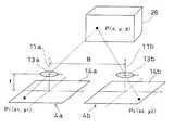
図6を参照して2つの画像に基づくステレオ測定について説明する。図6中、Bは2つのカメラ4a,4bのレンズ中心間距離(撮影基線長)、fは対物レンズ13a,13bの焦点距離、(x1,y1)は前記カメラ4aの画像座標、(x2,y2)は前記カメラ4bの画像座標、(x,y,z)は前記広角撮像装置1の3次元座標を示す。又、26は測定対象物である。 Stereo measurement based on two images will be described with reference to FIG. In FIG. 6, B is the distance between the lens centers of the two
又、説明を容易にする為、図6中では、前記カメラ4a,4bの光軸11a,11bを平行として示している。本実施例の様にカメラ4a,4bの光軸間に角度を有している場合は、得られた結果を角度に対応して補正すればよい。 For ease of explanation, the
該測定対象物26上の測定点P(x,y,z)と前記受光面14a,受光面14bの対応点P1(x1,y1),P2(x2,y2)の座標の間には以下の式に示す関係がある。 Between the measurement point P (x, y, z) on the
x=x1×B/(x1−x2)
y=y1×B/(x1−x2)
z=f×B/(x1−x2)
B:撮影基線長x = x1 * B / (x1-x2)
y = y1 * B / (x1-x2)
z = f * B / (x1-x2)
B: Shooting baseline length
従って、上記式により、対象物Pの空間座標中の相対的な位置座標P(x,y,z)を求めることができる。 Therefore, the relative position coordinates P (x, y, z) in the space coordinates of the object P can be obtained by the above formula.
尚、ここでは、簡易的な説明を行う為に同一平面内にカメラが位置したときの演算を例にしている。通常は、撮影基線に対して光軸を直角にしてそれぞれの画像を撮影することは難しく、各カメラの相対的な傾きを求める相互標定を行う。相互標定については、特開2005−165468号公報、特開2006−10376号公報等に記載されている。 Here, for the sake of simple explanation, the calculation when the camera is located in the same plane is taken as an example. Normally, it is difficult to capture each image with the optical axis at a right angle to the imaging baseline, and relative orientation is used to determine the relative tilt of each camera. The relative orientation is described in JP-A-2005-165468, JP-A-2006-10376, and the like.
尚、前記測定点Pは、抽出した測定対象物26の画像をエッジ処理する等して選定することができる。 The measurement point P can be selected by performing edge processing on the extracted image of the
而して、前記広角撮像装置1により広画角の画像を取得できると共に測定対象物26迄の測距を併せて行うことができる。 Thus, the wide-
又、前記表示部18をタッチパネルとして、該表示部18から測定点Pを選択し、距離測定を行うことができる。 Further, the
例えば、前記表示部18に表示する画像を、画角310゜の全体画像にするか、或は前記オーバラップ部分25とするかを選択可能とし、該オーバラップ部分25を前記表示部18に表示させた状態で、タッチペン等で画像中の測定したい位置を指示する。画像中で、測定点Pを指示することで、カメラ4aの受光面14a上の対応点P1(x1,y1)、カメラ4bの受光面14b上の対応点P2(x2,y2)を与えることになり、上記式により、x,yを求めることができる。 For example, it is possible to select whether the image to be displayed on the
上記したステレオ測定の精度は、次の式の通り表現される。
平面精度 ΔXY=H×Δp/f
奥行き方向の精度 ΔZ=(H/f)×(H/B)×Δp
H:測定対象物迄の距離
f:カメラの焦点距離
B:撮影基線長
Δp:カメラの画素サイズ
従って、上記した広角撮像装置1が取得した1地点での画像に基づくステレオ測定により遠距離を測定する場合は、精度が低下する。The accuracy of the stereo measurement described above is expressed as the following equation.
Planar accuracy ΔXY = H × Δp / f
Accuracy in depth direction ΔZ = (H / f) × (H / B) × Δp
H: Distance to the measurement object f: Camera focal length B: Shooting baseline length Δp: Pixel size of the camera Accordingly, a long distance is measured by stereo measurement based on the image at one point acquired by the wide-
従って、遠距離を測定する場合は、前記広角撮像装置1を移動させ、2地点で取得した2画像及び2地点間の距離に基づいてステレオ測定を行えばよい。 Therefore, when measuring a long distance, the wide-
移動に際し連続して撮像可能な測定対象物は、2地点で取得した2画像、及び2地点間の距離に基づくステレオ測定を行い、又、移動の為に連続して撮像ができない測定対象物は、前記カメラ4a,4bのオーバラップ画像によるステレオ測定を行い、測定対象物の距離、位置に応じて、前記2つのステレオ測定を切替えて行ってもよい。 The measurement object that can be imaged continuously during the movement is a stereo measurement based on the two images acquired at two points and the distance between the two points, and the measurement object that cannot be continuously imaged due to the movement is The stereo measurement may be performed using the overlap images of the
次に、前記自動車2にGPS装置を搭載し、前記自動車2の現在位置を測定可能とした場合を説明する。 Next, a case where a GPS device is mounted on the
GPS装置は、複数の衛星からの信号により、現在位置がリアルタイム測定できるものであり、前記広角撮像装置1による2点間の撮像地点の位置が測定でき、更に2点間の距離が演算できるので、移動しながら測定対象物の3次元座標を測定できる。 The GPS device can measure the current position in real time by signals from a plurality of satellites, can measure the position of the imaging point between the two points by the wide-
又、移動しながら測定を行う場合、近距離の測定対象物、例えば道路際に存在する建築物等については、自動車2に対する相対速度が速く、2点間で撮像し、GPS装置を使用する測定では、画像がかけ離れすぎて測定が難しくなる。 In addition, when measuring while moving, for a measurement object at a short distance, such as a building existing on the road, the relative speed with respect to the
従って、近距離では、前記広角撮像装置1で1地点で取得した画像で測定を行い、遠距離では2地点で取得した2画像に基づいて測定を行うことで、近距離から遠距離迄最適な状態で3次元座標測定を行うことができる。 Accordingly, the measurement is performed using the image acquired at one point by the wide-
GPS装置を用いた場合、前記自動車2の地上座標系の位置が分るので、前記広角撮像装置1で1地点で取得した画像での測定結果を地上座標系に置換えることができ、近距離から遠距離迄の測定結果を地図データとして利用することができる。 When a GPS device is used, since the position of the ground coordinate system of the
又、GPS装置の替わりに、IMU(慣性姿勢計測装置)を用いてもよい。IMUは搭載した移動体の相対的な位置を高精度に求めることが可能である。従って、IMUを用いて、撮像を行った2地点の相対位置関係を求め、ステレオ測定を行う。GPS装置、IMUは共に移動量測定手段として機能する。 Further, an IMU (Inertial Attitude Measurement Device) may be used instead of the GPS device. The IMU can obtain the relative position of the mounted mobile body with high accuracy. Therefore, the IMU is used to determine the relative positional relationship between the two locations where the image was taken and to perform stereo measurement. Both the GPS device and the IMU function as movement amount measuring means.
又、前記広角撮像装置1で取得した画像と3次元座標測距結果とを関連付けることで、位置データ付の画像とすることもできる。 In addition, an image with position data can be obtained by associating the image acquired by the wide-
上記実施例では、2つのカメラ4a,4bによる広角画像を取得可能としたが、3以上のカメラ4を円周に沿って配設することで全周カメラとすることができる。 In the above embodiment, wide-angle images can be acquired by the two
例えば、図7に示される様に、220゜の広画角を有するカメラ4a,4b,4c,4dを円周方向90゜間隔で配設すると、全周画像が取得できる。更に、隣接するカメラ毎にオーバラップ部分25a,25b,25c,25dが生じ、該オーバラップ部分25a,25b,25c,25dに存在する測定対象物が測定可能となる。 For example, as shown in FIG. 7, if
尚、図7中、ハッチングの付していない空白の部分は、ステレオ測定ができない死角部分となるが、死角部分は、広角撮像装置1の近傍に限られるので、実際の測定には殆ど影響がない。又、死角部分を少なくするには、前記カメラ4を72゜間隔で5、又は60゜間隔で6設置する等、カメラ4の数を増やすことで対応できる。更に、カメラ4の数については、カメラ4の画角に応じて適切なオーバラップ部分25ができる様適宜決定される。又、使用されるカメラ4は必ずしも広角カメラである必要はなく、測定対象物26を含む適宜なオーバラップ部分25が形成される様なカメラ4の数、配置であればよい。 In FIG. 7, a blank portion without hatching is a blind spot portion where stereo measurement cannot be performed. However, since the blind spot portion is limited to the vicinity of the wide-
更に又、上記実施例ではカメラ4の光軸を水平面に配置したが、垂直面内に配置し、上下方向に広角となる様にしてもよい。 Furthermore, in the above embodiment, the optical axis of the
広角撮像装置1により全周画像を取得できる様にした場合、前記表示部18にオーバラップ部分25a,25b,25c,25dを表示させると、オーバラップ部分のみで全周画像が得られる。従って、前記表示部18にオーバラップ部分のみの全周画像を表示させると、全周の任意方向の、任意な対象物の、任意な位置についてタッチペン等で指示することで、任意な位置の3次元座標測定が可能となる。而して、その都度測定方向に測定機を向けることなく、一度のセットで全周に存在する測定対象物の3次元座標測定ができる。 When the full-angle image can be acquired by the wide-
又、全周画像を取得できる様に、カメラを配置した場合に、隣接する少なくとも1組のカメラで前記オーバラップ部分25ができる様にしてもよい。 In addition, when the cameras are arranged so that the entire circumference image can be acquired, the
上記説明では、広角撮像装置1を自動車2に搭載した場合を説明したが、自動車の他に建設機械、農業機械等の移動体に搭載してもよい。 In the above description, the case where the wide-
又、前記演算処理装置7を前記ケース3内に設け、前記広角撮像装置1と前記演算処理装置7とを一体化し、更に又表示部18を一体化し、前記広角撮像装置1が測距機能を有する様にし、前記広角撮像装置1により広角画像を撮像すると同時に測定対象物についての3次元座標測定が行える様にしてもよい。 Further, the
1 広角撮像装置
2 自動車
3 ケース
4 カメラ
7 演算処理装置
11 光軸
12 受光素子
13 対物レンズ
14 受光面
16 測定システム
18 表示部
21 入出力制御部
22 演算部
23 記憶部
25 オーバラップ部分
26 測定対象物DESCRIPTION OF
Claims (8)
Translated fromJapanesePriority Applications (4)
| Application Number | Priority Date | Filing Date | Title |
|---|---|---|---|
| JP2009230576AJP5337658B2 (en) | 2009-10-02 | 2009-10-02 | Wide-angle imaging device and measurement system |
| CN201080044489.2ACN102511162B (en) | 2009-10-02 | 2010-09-08 | Wide-angle camera apparatus and Analytical system |
| PCT/JP2010/065890WO2011040239A1 (en) | 2009-10-02 | 2010-09-08 | Wide angle imaging device and measurement system |
| US13/393,354US9733080B2 (en) | 2009-10-02 | 2010-09-08 | Wide-angle image pickup unit and measuring device |
Applications Claiming Priority (1)
| Application Number | Priority Date | Filing Date | Title |
|---|---|---|---|
| JP2009230576AJP5337658B2 (en) | 2009-10-02 | 2009-10-02 | Wide-angle imaging device and measurement system |
Publications (2)
| Publication Number | Publication Date |
|---|---|
| JP2011082598A JP2011082598A (en) | 2011-04-21 |
| JP5337658B2true JP5337658B2 (en) | 2013-11-06 |
Family
ID=43826065
Family Applications (1)
| Application Number | Title | Priority Date | Filing Date |
|---|---|---|---|
| JP2009230576AExpired - Fee RelatedJP5337658B2 (en) | 2009-10-02 | 2009-10-02 | Wide-angle imaging device and measurement system |
Country Status (4)
| Country | Link |
|---|---|
| US (1) | US9733080B2 (en) |
| JP (1) | JP5337658B2 (en) |
| CN (1) | CN102511162B (en) |
| WO (1) | WO2011040239A1 (en) |
Cited By (1)
| Publication number | Priority date | Publication date | Assignee | Title |
|---|---|---|---|---|
| JPH0647911B2 (en) | 1988-03-11 | 1994-06-22 | 株式会社大林組 | Shield machine |
Families Citing this family (16)
| Publication number | Priority date | Publication date | Assignee | Title |
|---|---|---|---|---|
| WO2012156462A2 (en)* | 2011-05-17 | 2012-11-22 | Werth Messtechnik Gmbh | Method for generating and evaluating an image |
| GB201117143D0 (en) | 2011-10-05 | 2011-11-16 | Nctech Ltd | Camera |
| EP2846531A4 (en)* | 2012-05-01 | 2015-12-02 | Central Engineering Co Ltd | Stereo camera and stereo camera system |
| US10126745B2 (en) | 2015-01-04 | 2018-11-13 | Hangzhou Zero Zero Technology Co., Ltd. | System and method for automated aerial system operation |
| US9836053B2 (en) | 2015-01-04 | 2017-12-05 | Zero Zero Robotics Inc. | System and method for automated aerial system operation |
| US10358214B2 (en) | 2015-01-04 | 2019-07-23 | Hangzhou Zero Zro Technology Co., Ltd. | Aerial vehicle and method of operation |
| US10220172B2 (en) | 2015-11-25 | 2019-03-05 | Resmed Limited | Methods and systems for providing interface components for respiratory therapy |
| US10435144B2 (en) | 2016-04-24 | 2019-10-08 | Hangzhou Zero Zero Technology Co., Ltd. | Aerial system propulsion assembly and method of use |
| WO2017205642A1 (en)* | 2016-05-25 | 2017-11-30 | Livit Media Inc. | Methods and systems for live sharing 360-degree video streams on a mobile device |
| US20180131710A1 (en)* | 2016-11-07 | 2018-05-10 | Microsoft Technology Licensing, Llc | Network telephony anomaly detection images |
| US10067513B2 (en) | 2017-01-23 | 2018-09-04 | Hangzhou Zero Zero Technology Co., Ltd | Multi-camera system and method of use |
| JP6937126B2 (en) | 2017-01-31 | 2021-09-22 | 株式会社トプコン | Rover and rover measurement system |
| KR101898541B1 (en)* | 2017-04-14 | 2018-09-14 | 한국항공우주연구원 | Distance calculation system of moving device |
| US10300573B2 (en) | 2017-05-24 | 2019-05-28 | Trimble Inc. | Measurement, layout, marking, firestop stick |
| US10341618B2 (en)* | 2017-05-24 | 2019-07-02 | Trimble Inc. | Infrastructure positioning camera system |
| JP6909641B2 (en) | 2017-05-31 | 2021-07-28 | 株式会社小松製作所 | Display system |
Family Cites Families (45)
| Publication number | Priority date | Publication date | Assignee | Title |
|---|---|---|---|---|
| JP2515101B2 (en)* | 1986-06-27 | 1996-07-10 | ヤマハ株式会社 | Video and audio space recording / playback method |
| US5864360A (en)* | 1993-08-26 | 1999-01-26 | Canon Kabushiki Kaisha | Multi-eye image pick-up apparatus with immediate image pick-up |
| US6327381B1 (en)* | 1994-12-29 | 2001-12-04 | Worldscape, Llc | Image transformation and synthesis methods |
| US5703961A (en)* | 1994-12-29 | 1997-12-30 | Worldscape L.L.C. | Image transformation and synthesis methods |
| US5657073A (en)* | 1995-06-01 | 1997-08-12 | Panoramic Viewing Systems, Inc. | Seamless multi-camera panoramic imaging with distortion correction and selectable field of view |
| US5988862A (en) | 1996-04-24 | 1999-11-23 | Cyra Technologies, Inc. | Integrated system for quickly and accurately imaging and modeling three dimensional objects |
| JP3752063B2 (en)* | 1997-09-18 | 2006-03-08 | 松下電器産業株式会社 | Omnidirectional stereo imaging device |
| WO2000039995A2 (en)* | 1998-09-17 | 2000-07-06 | Yissum Research Development Company | System and method for generating and displaying panoramic images and movies |
| JP2000194983A (en) | 1998-12-28 | 2000-07-14 | Nichireki Co Ltd | Road surface and roadside photographing vehicle |
| JP4486737B2 (en) | 2000-07-14 | 2010-06-23 | アジア航測株式会社 | Spatial information generation device for mobile mapping |
| IL139995A (en)* | 2000-11-29 | 2007-07-24 | Rvc Llc | System and method for spherical stereoscopic photographing |
| US7126630B1 (en)* | 2001-02-09 | 2006-10-24 | Kujin Lee | Method and apparatus for omni-directional image and 3-dimensional data acquisition with data annotation and dynamic range extension method |
| CN1531826A (en) | 2001-02-09 | 2004-09-22 | Method and apparatus for omni-directional image and 3-dimensional data acquisition with data annotation and dynamic range extension method | |
| GB2372659A (en)* | 2001-02-23 | 2002-08-28 | Sharp Kk | A method of rectifying a stereoscopic image |
| JP3781281B2 (en) | 2001-10-30 | 2006-05-31 | 三井住友建設株式会社 | Method and apparatus for measuring route facilities |
| JP2004151043A (en) | 2002-11-01 | 2004-05-27 | Nippon Telegr & Teleph Corp <Ntt> | Attitude / Position Measuring Device, Attitude / Position Measuring Method, Program of This Method, and Recording Medium Recording This Program |
| US7463280B2 (en)* | 2003-06-03 | 2008-12-09 | Steuart Iii Leonard P | Digital 3D/360 degree camera system |
| JP2005106614A (en)* | 2003-09-30 | 2005-04-21 | Tdk Corp | Jig for calibrating three-dimensional camera, and method for calibrating camera |
| JP4446041B2 (en)* | 2003-10-02 | 2010-04-07 | 株式会社岩根研究所 | Camera vector computing device, shake component detecting device, image stabilizing device, position and orientation stabilizing device, target object lock-on device, and live-action object attribute calling device provided in this camera vector computing device |
| JP4427305B2 (en) | 2003-11-28 | 2010-03-03 | 株式会社トプコン | Three-dimensional image display apparatus and method |
| US7787009B2 (en)* | 2004-05-10 | 2010-08-31 | University Of Southern California | Three dimensional interaction with autostereoscopic displays |
| US20070182812A1 (en)* | 2004-05-19 | 2007-08-09 | Ritchey Kurtis J | Panoramic image-based virtual reality/telepresence audio-visual system and method |
| JP4488804B2 (en) | 2004-06-23 | 2010-06-23 | 株式会社トプコン | Stereo image association method and three-dimensional data creation apparatus |
| JP2006033570A (en)* | 2004-07-20 | 2006-02-02 | Olympus Corp | Image generating device |
| US8114172B2 (en)* | 2004-07-30 | 2012-02-14 | Extreme Reality Ltd. | System and method for 3D space-dimension based image processing |
| JP5225542B2 (en) | 2004-09-22 | 2013-07-03 | 三菱電機株式会社 | MAP INFORMATION GENERATION METHOD, MAP INFORMATION GENERATION PROGRAM, AND MAP INFORMATION COLLECTION DEVICE |
| US7791638B2 (en)* | 2004-09-29 | 2010-09-07 | Immersive Media Co. | Rotating scan camera |
| US7982777B2 (en)* | 2005-04-07 | 2011-07-19 | Axis Engineering Technologies, Inc. | Stereoscopic wide field of view imaging system |
| US8024144B2 (en)* | 2005-09-12 | 2011-09-20 | Trimble Jena Gmbh | Surveying instrument and method of providing survey data of a target region using a surveying instrument |
| US20070285554A1 (en)* | 2005-10-31 | 2007-12-13 | Dor Givon | Apparatus method and system for imaging |
| US9270976B2 (en)* | 2005-11-02 | 2016-02-23 | Exelis Inc. | Multi-user stereoscopic 3-D panoramic vision system and method |
| US20100045773A1 (en)* | 2007-11-06 | 2010-02-25 | Ritchey Kurtis J | Panoramic adapter system and method with spherical field-of-view coverage |
| JP5362189B2 (en)* | 2006-05-10 | 2013-12-11 | 株式会社トプコン | Image processing apparatus and processing method thereof |
| JP4926822B2 (en)* | 2006-05-24 | 2012-05-09 | 株式会社岩根研究所 | Spring point reference CV region image pre-placement device |
| JP2008102620A (en)* | 2006-10-17 | 2008-05-01 | Toyota Motor Corp | Image processing device |
| US8269820B2 (en)* | 2006-11-02 | 2012-09-18 | Konica Minolta Holdings, Inc. | Wide-angle image acquiring method and wide-angle stereo camera device |
| CN101652628B (en)* | 2007-01-26 | 2012-07-04 | 特里伯耶拿有限公司 | Optical instrument and method for obtaining distance and image information |
| JP4935412B2 (en) | 2007-02-22 | 2012-05-23 | 日本電気株式会社 | Portable information processing apparatus, communication processing method for portable information processing apparatus, and communication processing program for portable information processing apparatus |
| EP2149067A1 (en)* | 2007-04-19 | 2010-02-03 | D.V.P. Technologies Ltd. | Imaging system and method for use in monitoring a field of regard |
| US20080298674A1 (en)* | 2007-05-29 | 2008-12-04 | Image Masters Inc. | Stereoscopic Panoramic imaging system |
| WO2008153127A1 (en)* | 2007-06-15 | 2008-12-18 | Kabushiki Kaisha Toshiba | Instrument for examining/measuring object to be measured |
| US20090237490A1 (en)* | 2008-03-21 | 2009-09-24 | Nelson Jr Douglas V | System and method for stereoscopic image creation and transmission |
| CN100557379C (en)* | 2008-04-24 | 2009-11-04 | 吉林大学 | Binocular Stereo Vision Measuring Method of Spatial Circle Geometric Parameters |
| JP4669539B2 (en) | 2008-10-01 | 2011-04-13 | 株式会社トプコン | Imaging device, in-vehicle camera, and surveillance camera |
| JP5432545B2 (en) | 2009-02-25 | 2014-03-05 | 株式会社トプコン | Object detection device |
- 2009
- 2009-10-02JPJP2009230576Apatent/JP5337658B2/ennot_activeExpired - Fee Related
- 2010
- 2010-09-08WOPCT/JP2010/065890patent/WO2011040239A1/enactiveApplication Filing
- 2010-09-08CNCN201080044489.2Apatent/CN102511162B/ennot_activeExpired - Fee Related
- 2010-09-08USUS13/393,354patent/US9733080B2/ennot_activeExpired - Fee Related
Cited By (1)
| Publication number | Priority date | Publication date | Assignee | Title |
|---|---|---|---|---|
| JPH0647911B2 (en) | 1988-03-11 | 1994-06-22 | 株式会社大林組 | Shield machine |
Also Published As
| Publication number | Publication date |
|---|---|
| WO2011040239A1 (en) | 2011-04-07 |
| US20120162360A1 (en) | 2012-06-28 |
| JP2011082598A (en) | 2011-04-21 |
| CN102511162B (en) | 2015-09-09 |
| CN102511162A (en) | 2012-06-20 |
| US9733080B2 (en) | 2017-08-15 |
Similar Documents
| Publication | Publication Date | Title |
|---|---|---|
| JP5337658B2 (en) | Wide-angle imaging device and measurement system | |
| CN104662389B (en) | Surrounding information acquisition device of work vehicle | |
| CN105606077B (en) | Geodetic Measuring System | |
| KR101885704B1 (en) | Calibration system, and calibration method for work machine | |
| JP6181388B2 (en) | Measuring device | |
| JP2016057108A (en) | Arithmetic apparatus, arithmetic system, arithmetic method and program | |
| JP6211157B1 (en) | Calibration apparatus and calibration method | |
| JP6507268B2 (en) | Photography support apparatus and photography support method | |
| JP7203105B2 (en) | CALIBRATION DEVICE, MONITORING DEVICE, WORKING MACHINE, AND CALIBRATION METHOD FOR IMAGE SENSOR | |
| JP6177006B2 (en) | Camera calibration apparatus and camera calibration method | |
| KR101076803B1 (en) | Map constructing method of inhouse robot and start position determining method thereof | |
| JP6930840B2 (en) | Surveying system | |
| JP6058483B2 (en) | Aerial surveying method and apparatus | |
| JP4649192B2 (en) | Stereo image creation method and three-dimensional data creation apparatus | |
| JP6001914B2 (en) | Target position specifying device, target position specifying system, and target position specifying method | |
| JP4783620B2 (en) | 3D data creation method and 3D data creation apparatus | |
| JP2005091298A (en) | Global coordinate acquisition device using image processing | |
| JP6080450B2 (en) | Surveillance camera device | |
| JP2019533875A (en) | Method and system for generating a composite top view image of a road | |
| KR101409802B1 (en) | System for analysis space information using three dimensions 3d scanner | |
| JP6368503B2 (en) | Obstacle monitoring system and program | |
| WO2020024150A1 (en) | Map processing method, apparatus, and computer readable storage medium | |
| JP7278637B2 (en) | Self-propelled moving device | |
| JP4522756B2 (en) | Surveying work guidance device | |
| JP2010281685A (en) | Position measuring system and position measuring method |
Legal Events
| Date | Code | Title | Description |
|---|---|---|---|
| A621 | Written request for application examination | Free format text:JAPANESE INTERMEDIATE CODE: A621 Effective date:20120830 | |
| A131 | Notification of reasons for refusal | Free format text:JAPANESE INTERMEDIATE CODE: A131 Effective date:20130312 | |
| A521 | Request for written amendment filed | Free format text:JAPANESE INTERMEDIATE CODE: A523 Effective date:20130508 | |
| TRDD | Decision of grant or rejection written | ||
| A01 | Written decision to grant a patent or to grant a registration (utility model) | Free format text:JAPANESE INTERMEDIATE CODE: A01 Effective date:20130723 | |
| A61 | First payment of annual fees (during grant procedure) | Free format text:JAPANESE INTERMEDIATE CODE: A61 Effective date:20130805 | |
| R150 | Certificate of patent or registration of utility model | Ref document number:5337658 Country of ref document:JP Free format text:JAPANESE INTERMEDIATE CODE: R150 Free format text:JAPANESE INTERMEDIATE CODE: R150 | |
| R250 | Receipt of annual fees | Free format text:JAPANESE INTERMEDIATE CODE: R250 | |
| R250 | Receipt of annual fees | Free format text:JAPANESE INTERMEDIATE CODE: R250 | |
| R250 | Receipt of annual fees | Free format text:JAPANESE INTERMEDIATE CODE: R250 | |
| R250 | Receipt of annual fees | Free format text:JAPANESE INTERMEDIATE CODE: R250 | |
| R250 | Receipt of annual fees | Free format text:JAPANESE INTERMEDIATE CODE: R250 | |
| R250 | Receipt of annual fees | Free format text:JAPANESE INTERMEDIATE CODE: R250 | |
| R250 | Receipt of annual fees | Free format text:JAPANESE INTERMEDIATE CODE: R250 | |
| R250 | Receipt of annual fees | Free format text:JAPANESE INTERMEDIATE CODE: R250 | |
| LAPS | Cancellation because of no payment of annual fees |