JP5336959B2 - Probe microscope - Google Patents
Probe microscopeDownload PDFInfo
- Publication number
- JP5336959B2 JP5336959B2JP2009164589AJP2009164589AJP5336959B2JP 5336959 B2JP5336959 B2JP 5336959B2JP 2009164589 AJP2009164589 AJP 2009164589AJP 2009164589 AJP2009164589 AJP 2009164589AJP 5336959 B2JP5336959 B2JP 5336959B2
- Authority
- JP
- Japan
- Prior art keywords
- light
- displacement
- measured
- cantilever
- displacement detection
- Prior art date
- Legal status (The legal status is an assumption and is not a legal conclusion. Google has not performed a legal analysis and makes no representation as to the accuracy of the status listed.)
- Expired - Fee Related
Links
- 239000000523sampleSubstances0.000titleclaimsabstractdescription92
- 238000006073displacement reactionMethods0.000claimsabstractdescription166
- 238000001514detection methodMethods0.000claimsabstractdescription124
- 230000003287optical effectEffects0.000claimsabstractdescription119
- 238000003384imaging methodMethods0.000claimsdescription50
- 238000005259measurementMethods0.000claimsdescription19
- 230000001678irradiating effectEffects0.000claimsdescription14
- 238000010586diagramMethods0.000description17
- 230000000694effectsEffects0.000description10
- 239000011521glassSubstances0.000description7
- 239000000463materialSubstances0.000description7
- 238000000034methodMethods0.000description6
- 238000006243chemical reactionMethods0.000description3
- 230000004075alterationEffects0.000description2
- 230000008859changeEffects0.000description2
- 230000004048modificationEffects0.000description2
- 238000012986modificationMethods0.000description2
- 239000012466permeateSubstances0.000description2
- 238000004519manufacturing processMethods0.000description1
Images


Classifications
- G—PHYSICS
- G01—MEASURING; TESTING
- G01B—MEASURING LENGTH, THICKNESS OR SIMILAR LINEAR DIMENSIONS; MEASURING ANGLES; MEASURING AREAS; MEASURING IRREGULARITIES OF SURFACES OR CONTOURS
- G01B9/00—Measuring instruments characterised by the use of optical techniques
- G01B9/02—Interferometers
- G01B9/02015—Interferometers characterised by the beam path configuration
- G01B9/02027—Two or more interferometric channels or interferometers
- B—PERFORMING OPERATIONS; TRANSPORTING
- B82—NANOTECHNOLOGY
- B82Y—SPECIFIC USES OR APPLICATIONS OF NANOSTRUCTURES; MEASUREMENT OR ANALYSIS OF NANOSTRUCTURES; MANUFACTURE OR TREATMENT OF NANOSTRUCTURES
- B82Y35/00—Methods or apparatus for measurement or analysis of nanostructures
- G—PHYSICS
- G01—MEASURING; TESTING
- G01B—MEASURING LENGTH, THICKNESS OR SIMILAR LINEAR DIMENSIONS; MEASURING ANGLES; MEASURING AREAS; MEASURING IRREGULARITIES OF SURFACES OR CONTOURS
- G01B9/00—Measuring instruments characterised by the use of optical techniques
- G01B9/02—Interferometers
- G01B9/02001—Interferometers characterised by controlling or generating intrinsic radiation properties
- G01B9/02007—Two or more frequencies or sources used for interferometric measurement
- G—PHYSICS
- G01—MEASURING; TESTING
- G01Q—SCANNING-PROBE TECHNIQUES OR APPARATUS; APPLICATIONS OF SCANNING-PROBE TECHNIQUES, e.g. SCANNING PROBE MICROSCOPY [SPM]
- G01Q20/00—Monitoring the movement or position of the probe
- G01Q20/02—Monitoring the movement or position of the probe by optical means
- G—PHYSICS
- G01—MEASURING; TESTING
- G01B—MEASURING LENGTH, THICKNESS OR SIMILAR LINEAR DIMENSIONS; MEASURING ANGLES; MEASURING AREAS; MEASURING IRREGULARITIES OF SURFACES OR CONTOURS
- G01B2290/00—Aspects of interferometers not specifically covered by any group under G01B9/02
- G01B2290/45—Multiple detectors for detecting interferometer signals
Landscapes
- Physics & Mathematics (AREA)
- General Physics & Mathematics (AREA)
- Chemical & Material Sciences (AREA)
- Engineering & Computer Science (AREA)
- Nanotechnology (AREA)
- Health & Medical Sciences (AREA)
- General Health & Medical Sciences (AREA)
- Nuclear Medicine, Radiotherapy & Molecular Imaging (AREA)
- Radiology & Medical Imaging (AREA)
- Analytical Chemistry (AREA)
- Crystallography & Structural Chemistry (AREA)
- Length Measuring Devices By Optical Means (AREA)
Abstract
Description
Translated fromJapanese本発明は、プローブ顕微鏡に関し、特に被測定物に接触する探針を有するカンチレバーの変位を検出するための第1の変位検出光学系と、被測定物の変位を検出するための第2の変位検出光学系とを備えるプローブ顕微鏡に関する。 The present invention relates to a probe microscope, and in particular, a first displacement detection optical system for detecting the displacement of a cantilever having a probe that contacts the object to be measured, and a second displacement for detecting the displacement of the object to be measured. The present invention relates to a probe microscope including a detection optical system.
従来、被測定物に接触する探針を有するカンチレバーと、カンチレバーの変位を検出するための第1の変位検出光学系と、被測定物の変位を検出するための第2の変位検出光学系とを備え、被測定物の表面を走査することで被測定物の表面形状を観察するプローブ顕微鏡が知られている(例えば、特許文献1参照)。
特許文献1に記載の走査型プローブ顕微鏡装置(プローブ顕微鏡)は、カンチレバーと、カンチレバーにレーザビームを照射することでカンチレバーの変位を検出するプローブ顕微鏡(第1の変位検出光学系)と、被測定物にレーザビームを照射することで被測定物の変位を検出するレーザ顕微鏡(第2の変位検出光学系)とを備えている。また、走査型プローブ顕微鏡装置は、レーザビームの方向を変更することによって、カンチレバーにレーザビームを照射する光路と、被測定物にレーザビームを照射する光路とを変換する光路変換部を備えている。そして、走査型プローブ顕微鏡装置は、光路変換部にて光路の変換をすることで、プローブ顕微鏡によるカンチレバーの変位の検出と、レーザ顕微鏡による被測定物の変位の検出とを切り替えている。Conventionally, a cantilever having a probe in contact with the object to be measured, a first displacement detection optical system for detecting the displacement of the cantilever, and a second displacement detection optical system for detecting the displacement of the object to be measured There is known a probe microscope that observes the surface shape of the object to be measured by scanning the surface of the object to be measured (see, for example, Patent Document 1).
A scanning probe microscope apparatus (probe microscope) described in Patent Document 1 includes a cantilever, a probe microscope (first displacement detection optical system) that detects the displacement of the cantilever by irradiating the cantilever with a laser beam, and a measurement target. A laser microscope (second displacement detection optical system) that detects the displacement of the object to be measured by irradiating the object with a laser beam is provided. Further, the scanning probe microscope apparatus includes an optical path conversion unit that converts an optical path for irradiating the laser beam to the cantilever and an optical path for irradiating the measured object with the laser beam by changing the direction of the laser beam. . The scanning probe microscope apparatus switches between detecting the displacement of the cantilever by the probe microscope and detecting the displacement of the object to be measured by the laser microscope by converting the optical path in the optical path conversion unit.
しかしながら、特許文献1に記載の走査型プローブ顕微鏡装置では、光路変換部にて光路の変換をすることで、プローブ顕微鏡によるカンチレバーの変位の検出と、レーザ顕微鏡による被測定物の変位の検出とを切り替えているので、被測定物における同一の箇所を測定することが困難であるという問題がある。また、プローブ顕微鏡、及びレーザ顕微鏡は、別体として構成されているので、走査型プローブ顕微鏡装置が大型化し、ひいては走査型プローブ顕微鏡装置の製造コストが増加するという問題がある。 However, in the scanning probe microscope apparatus described in Patent Document 1, the optical path is converted by the optical path conversion unit, thereby detecting the displacement of the cantilever by the probe microscope and detecting the displacement of the object to be measured by the laser microscope. Since they are switched, there is a problem that it is difficult to measure the same part in the object to be measured. In addition, since the probe microscope and the laser microscope are configured as separate bodies, there is a problem that the scanning probe microscope apparatus is enlarged and the manufacturing cost of the scanning probe microscope apparatus is increased.
本発明の目的は、第1変位検出光学系、及び第2変位検出光学系にて被測定物における同一の箇所を容易に測定することができ、第1変位検出光学系、及び第2変位検出光学系を一体化することができるプローブ顕微鏡を提供することにある。 An object of the present invention is to be able to easily measure the same portion of the object to be measured with the first displacement detection optical system and the second displacement detection optical system. The first displacement detection optical system and the second displacement detection An object of the present invention is to provide a probe microscope capable of integrating an optical system.
本発明のプローブ顕微鏡は、被測定物に接触する探針を有するカンチレバーと、前記カンチレバーの変位を検出するための第1の変位検出光学系と、前記被測定物の変位を検出するための第2の変位検出光学系とを備え、前記被測定物の表面を走査することで前記被測定物の表面形状を観察するプローブ顕微鏡であって、前記第1の変位検出光学系は、前記カンチレバーに光を照射するための第1の光源と、前記第1の光源から射出され、前記カンチレバーにて反射される反射光を受光することで前記カンチレバーの変位を検出する第1の変位検出手段とを備え、前記第2の変位検出光学系は、前記被測定物に前記第1の光源と異なる波長の光を照射するための第2の光源と、前記第2の光源から射出され、前記被測定物にて反射される反射光を受光することで前記被測定物の変位を検出する第2の変位検出手段とを備え、前記カンチレバーと、前記各光源との間に配設され、前記第1の光源から射出される光の波長に対して前記カンチレバーの位置を焦点とし、且つ、前記第2の光源から射出される光の波長に対して前記探針の先端位置より前記被測定物側の位置を焦点とする対物レンズを備え、前記第1,2の変位検出光学系は、前記第1,2の光源からそれぞれ射出される光を前記第1,2の光源と前記対物レンズとの間で平行化し、前記対物レンズは、前記平行化された前記第1,2の光源からの光が入射されるように、第1,2の変位検出光学系に共用されることを特徴とする。A probe microscope according to the present invention includes a cantilever having a probe that contacts the object to be measured, a first displacement detection optical system for detecting the displacement of the cantilever, and a first for detecting the displacement of the object to be measured. A displacement microscope, and a probe microscope for observing a surface shape of the object to be measured by scanning the surface of the object to be measured, wherein the first displacement detection optical system is attached to the cantilever. A first light source for irradiating light, and a first displacement detecting means for detecting the displacement of the cantilever by receiving reflected light emitted from the first light source and reflected by the cantilever. The second displacement detection optical system includes: a second light source for irradiating the object to be measured with light having a wavelength different from that of the first light source; the second light source being emitted from the second light source; Reflection reflected by objects Second displacement detecting means for detecting the displacement of the object to be measured by receiving the light, and disposed between the cantilever and each of the light sources, the light emitted from the first light source. An objective lens that focuseson the position of the cantilever with respect to the wavelength and focuseson the position of the object to be measured with respect to the wavelength of the light emitted from the second light source fromthe tip position of the probe. And thefirst and second displacement detection optical systems collimate light respectively emitted from the first and second light sources between the first and second light sources and the objective lens. The first and second displacement detection optical systems are used so that light from the collimated first and second light sources is incident thereon.
ここで、波長の長い光が対物レンズに入射したときの焦点距離は、対物レンズの色収差の影響によって波長の短い光が対物レンズに入射したときの焦点距離よりも長くなる。したがって、第1の光源から射出される光の波長、及び第2の光源から射出される光の波長に対する対物レンズの焦点距離は、対物レンズに用いられる硝材によって定めることができる。
本発明によれば、プローブ顕微鏡は、第1の光源から射出される光の波長に対してカンチレバーの位置を焦点とし、且つ、第2の光源から射出される光の波長に対して被測定物の位置を焦点とする対物レンズを備えるので、カンチレバーに光を照射する光路と、被測定物に光を照射する光路とを同じ光路とすることができる。したがって、第1変位検出光学系、及び第2変位検出光学系にて被測定物における同一の箇所を容易に測定することができ、第1変位検出光学系、及び第2変位検出光学系を一体化することができる。Here, the focal length when light having a long wavelength is incident on the objective lens is longer than the focal length when light having a short wavelength is incident on the objective lens due to the influence of chromatic aberration of the objective lens. Therefore, the focal length of the objective lens with respect to the wavelength of the light emitted from the first light source and the wavelength of the light emitted from the second light source can be determined by the glass material used for the objective lens.
According to the present invention, the probe microscope is focused on the position of the cantilever with respect to the wavelength of the light emitted from the first light source and is measured with respect to the wavelength of the light emitted from the second light source. Therefore, the optical path for irradiating the cantilever with light and the optical path for irradiating the object to be measured can be made the same optical path. Therefore, it is possible to easily measure the same portion of the object to be measured with the first displacement detection optical system and the second displacement detection optical system, and the first displacement detection optical system and the second displacement detection optical system are integrated. Can be
また、前記第2の光源から射出される光の波長に対する前記対物レンズの焦点を、前記探針の先端位置より前記被測定物側の位置としたので、第2の変位検出手段は、カンチレバーの探針と、被測定物とを離間させている状態で被測定物の変位を検出することができる。したがって、第2の変位検出光学系にて被測定物の変位を検出しているときに、カンチレバーの探針、及び被測定物の接触を防止することができ、探針の破損を防止することができる。
本発明では、前記被測定物を前記対物レンズに対して光軸方向へ移動させる手段を備える、ことが好ましい。Further, since the focal point of the objective lens with respect to the wavelength of the light emitted from the second light source is set to a position closer to the object to be measured with respect to the tip position of the probe, the second displacement detection means is configured as a cantilever. The displacement of the measurement object can be detected in a state where the probe and the measurement object are separated from each other. Therefore, when the displacement of the object to be measured is detected by the second displacement detection optical system, the contact between the cantilever probe and the object to be measured can be prevented, and the probe can be prevented from being damaged. Can do.
In this invention, it is preferable to provide the means to move the said to-be-measured object with respect to the said objective lens to an optical axis direction.
本発明では、前記各変位検出光学系は、所定の位置に設けられ、前記各光源から射出される光を反射する参照面を備え、前記各変位検出手段は、前記参照面にて反射される光と、前記反射光との干渉光に基づいて、変位を検出することが好ましい。
このような構成によれば、前述したプローブ顕微鏡と同様の作用効果を奏することができる。In the present invention, each displacement detection optical system includes a reference surface that is provided at a predetermined position and reflects light emitted from each light source, and each displacement detection unit is reflected by the reference surface. It is preferable to detect displacement based on interference light between the light and the reflected light.
According to such a configuration, the same operational effects as those of the probe microscope described above can be achieved.
本発明では、前記各変位検出光学系は、前記反射光を所定の位置に集光する結像レンズと、前記結像レンズにて集光される光を透過させるピンホールとを備え、前記各変位検出手段は、前記ピンホールを透過する光に基づいて、変位を検出することが好ましい。
このような構成によれば、前述したプローブ顕微鏡と同様の作用効果を奏することができる。In the present invention, each of the displacement detection optical systems includes an imaging lens that condenses the reflected light at a predetermined position, and a pinhole that transmits the light collected by the imaging lens. The displacement detection means preferably detects the displacement based on the light transmitted through the pinhole.
According to such a configuration, the same operational effects as those of the probe microscope described above can be achieved.
本発明では、前記結像レンズは、アクロマートレンズであることが好ましい。
このような構成によれば、アクロマートレンズは、透過する光の波長によって焦点の位置が変化しないので、各変位検出光学系は、第1の光源から射出される光と、第2の光源から射出される光とを切り替えることによって、結像レンズ、ピンホール、及び変位検出手段を共用することができる。したがって、プローブ顕微鏡の部品点数を削減することができる。In the present invention, the imaging lens is preferably an achromatic lens.
According to such a configuration, the position of the focal point of the achromatic lens does not change depending on the wavelength of the transmitted light, so that each displacement detection optical system emits the light emitted from the first light source and the second light source. The imaging lens, the pinhole, and the displacement detection means can be shared by switching the light to be generated. Therefore, the number of parts of the probe microscope can be reduced.
本発明では、前記第2の光源から射出され、前記被測定物にて反射される反射光を所定の位置に集光する結像レンズと、前記結像レンズにて集光される光を受光することで前記被測定物を観察する観察手段を備えることが好ましい。
このような構成によれば、プローブ顕微鏡は、第2の変位検出光学系にて被測定物の変位を検出するとともに、観察手段にて結像レンズの焦点距離に応じた倍率で被測定物を拡大して観察することができる。In the present invention, an imaging lens that collects reflected light emitted from the second light source and reflected by the object to be measured at a predetermined position, and light received by the imaging lens is received. It is preferable to provide an observation means for observing the object to be measured.
According to such a configuration, the probe microscope detects the displacement of the object to be measured by the second displacement detection optical system, and the object to be measured with the magnification according to the focal length of the imaging lens by the observation unit. It can be magnified and observed.
〔前提技術〕
以下、本発明の前提技術を図面に基づいて説明する。
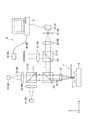
図1は、本発明の前提技術に係るプローブ顕微鏡1を示す模式図である。なお、図1では、鉛直上方向を+Z軸とし、このZ軸と直交する2軸をそれぞれX,Y軸としている。以下の図面においても同様である。
プローブ顕微鏡1は、図1に示すように、被測定物Wに接触する探針21を有するカンチレバー2と、第1の変位検出光学系3と、第2の変位検出光学系4と、各変位検出光学系3,4を一体化するための共用光学系5と、参照ミラー6と、対物レンズ7と、PC(Personal Computer)8とを備え、X軸、及びY軸方向に被測定物Wの表面を走査するこ
とで被測定物Wの表面形状を観察するものである。[Prerequisite technology ]
Hereinafter, theprerequisite technology of the present invention will be described with reference to the drawings.
FIG. 1 is a schematic diagram showing a probe microscope 1 according to thepremise technique of the present invention. In FIG. 1, the vertically upward direction is the + Z axis, and the two axes orthogonal to the Z axis are the X and Y axes, respectively. The same applies to the following drawings.
As shown in FIG. 1, the probe microscope 1 includes a
第1の変位検出光学系3は、カンチレバー2の変位を検出するためのものであり、共用光学系5、及び参照ミラー6を含んで構成される。なお、図1では、第1の変位検出光学系3における光路を実線で示している。以下の図面においても同様である。この第1の変位検出光学系3は、+Z軸方向側に配設され、カンチレバー2に光を照射するための第1の光源31と、第1の光源31から射出される光を平行化するコリメータレンズ32と、共用光学系5を介して入射した光を所定の位置に集光する結像レンズ33と、結像レンズ33にて集光される光の強度を検出する光検出素子34とを備える。 The first displacement detection
第2の変位検出光学系4は、被測定物Wの変位を検出するためのものであり、共用光学系5、及び参照ミラー6を含んで構成される。なお、図1では、第2の変位検出光学系4における光路を破線で示している。以下の図面においても同様である。この第2の変位検出光学系4は、−X軸方向側に配設され、被測定物Wに第1の光源31と異なる波長の光を照射するための第2の光源41と、第2の光源41から射出される光を平行化するコリメータレンズ42と、共用光学系5を介して入射した光を所定の位置に集光する結像レンズ43と、結像レンズ43にて集光される光の強度を検出する光検出素子44とを備える。
なお、光検出素子34,44による検出の結果は、PC8に出力されて処理される。すなわち、本実施形態では、第1の変位検出手段は、光検出素子34と、PC8とで構成され、第2の変位検出手段は、光検出素子44と、PC8とで構成されている。The second displacement detection
Note that the detection results of the
共用光学系5は、ビームスプリッタ51,52と、バンドパスフィルタ53とを備える。
各ビームスプリッタ51,52は、入射する光の一部を界面511,521にて反射させるとともに、他の一部を透過させるものであり、それぞれ同一の機能を有している。
バンドパスフィルタ53は、第1の光源31から射出され、光検出素子34に至る光と、第2の光源41から射出され、光検出素子34に至る光とを界面531にて分離する機能を有している。具体的に、界面531は、第1の光源31から射出される光を透過させ、第2の光源41から射出される光を反射させる。
参照ミラー6は、所定の位置に設けられ、入射した光を反射する参照面6Aを有している。The shared
Each of the
The
The
対物レンズ7は、カンチレバー2と、各光源31,41との間に配設され、各変位検出光学系3,4で共用している。また、対物レンズ7は、第1の光源31から射出される光の波長λ1に対してカンチレバー2の位置を焦点とし、且つ、第2の光源41から射出される光の波長λ2に対して探針21の先端位置を焦点とするように設計され、配置されている。すなわち、カンチレバー2の探針21を被測定物Wに接触させている状態では、対物レンズ7は、第2の光源41から射出される光の波長λ2に対して被測定物Wの位置を焦点とするように設計され、配置されている。 The
なお、本前提技術では、各波長λ1,λ2の関係は、λ1<λ2とされている。これは、波長の長い光が対物レンズ7に入射したときの焦点距離は、対物レンズ7の色収差の影響によって波長の短い光が対物レンズ7に入射したときの焦点距離よりも長くなるためである。ここで、各波長λ1,λ2に対する対物レンズ7の焦点距離は、対物レンズ7に用いられる硝材によって定まる。以下、これらの選定について説明する。In the basetechnology , the relationship between the wavelengths λ1 and λ2 is λ1 <λ2. This is because the focal length when light having a long wavelength is incident on the
図2は、第1の光源31から射出される光が対物レンズ7に入射したときの焦点距離fと、第2の光源41から射出される光が対物レンズ7に入射したときの焦点距離との関係を示す図である。
第1の光源31から射出される光の波長λ1に対する焦点距離f、及び第2の光源41から射出される光の波長λ2に対する焦点距離のシフト量を、図2に示すように、δfとすると、シフト量δfは、以下の式(1)で表される。なお、n1は、波長λ1における対物レンズ7の屈折率であり、n2は、波長λ2における対物レンズ7の屈折率である。FIG. 2 shows the focal length f when the light emitted from the
As shown in FIG. 2, when the focal length f with respect to the wavelength λ1 of the light emitted from the

図3は、代表的な硝材BK7の波長ごとの屈折率を示す図である。
例えば、対物レンズ7に用いられる硝材をBK7とし、波長λ1を656nm、波長λ2を780nmとし、シフト量δfをカンチレバー2の位置から探針21の先端位置までの長さ15μmとして、前述した式(1)に代入すると、以下の式(2)に示すように、波長λ1に対する対物レンズ7の焦点距離fは、2.56mmとなる。FIG. 3 is a diagram showing the refractive index for each wavelength of a typical glass material BK7.
For example, the glass material used for the
すなわち、対物レンズ7に用いられる硝材をBK7とし、波長λ1を656nm、波長λ2を780nmとした場合には、波長λ1に対する焦点距離f=2.56mmの対物レンズ7を採用することによって、対物レンズ7は、第1の光源31から射出される光の波長λ1に対してカンチレバー2の位置を焦点とし、且つ、第2の光源41から射出される光の波長λ2に対して探針21の先端位置を焦点とすることができる。 That is, when the glass material used for the
次に、変位検出光学系3における光路、すなわち第1の光源31から光検出素子34に至る光路について、図1を参照して説明する。
第1の光源31から射出された光は、コリメータレンズ32にて平行化され、ビームスプリッタ51に入射する。ビームスプリッタ51に入射した光の一部は、界面511を透過してビームスプリッタ52に入射する。ビームスプリッタ52に入射した光の一部は、界面521にて参照ミラー6に向かって反射され、他の一部は、界面521を透過して対物レンズ7に入射する。対物レンズ7に入射した光は、波長λ1に対する対物レンズ7の焦点の位置であるカンチレバー2の背面に集光される。Next, the optical path in the displacement detection
The light emitted from the
そして、参照ミラー6の参照面6Aにて反射された光(以下、参照光とする)、及びカンチレバー2にて反射された反射光(以下、測定光とする)は、ビームスプリッタ52に入射する。ビームスプリッタ52に入射した参照光の一部は、界面521を透過し、ビームスプリッタ52に入射した測定光の一部は、界面521にて反射される。したがって、参照光、及び測定光は、合成されて干渉光となってバンドパスフィルタ53に入射する。バンドパスフィルタ53に入射した干渉光は、界面531を透過して結像レンズ33に入射する。結像レンズ33に入射した干渉光は、所定の位置に集光される。結像レンズ33にて集光される干渉光は、光検出素子34に入射する。光検出素子34は、PC8による制御の下、結像レンズ33にて集光される干渉光を検出し、PC8は、検出された干渉光の強度に基づいてカンチレバー2の変位を検出する。すなわち、第1の変位検出手段は、第1の光源31から射出され、カンチレバー2にて反射される反射光を受光することでカンチレバー2の変位を検出する。 The light reflected on the
また、変位検出光学系4における光路、すなわち第2の光源41から光検出素子44に至る光路について説明する。
第2の光源41から射出された光は、コリメータレンズ42にて平行化され、ビームスプリッタ51に入射する。ビームスプリッタ51に入射した光の一部は、界面511にて反射され、ビームスプリッタ52に入射する。ビームスプリッタ52に入射した光の一部は、界面521にて参照ミラー6に向かって反射され、他の一部は、界面521を透過して対物レンズ7に入射する。対物レンズ7に入射した光は、波長λ2に対する対物レンズ7の焦点の位置である探針21の先端位置に集光される。Further, the optical path in the displacement detection
The light emitted from the second
そして、参照ミラー6の参照面6Aにて反射された光(以下、参照光とする)、及び被測定物Wにて反射された反射光(以下、測定光とする)は、ビームスプリッタ52に入射する。ビームスプリッタ52に入射した参照光の一部は、界面521を透過し、ビームスプリッタ52に入射した測定光の一部は、界面521にて反射される。したがって、参照光、及び測定光は、合成されて干渉光となってバンドパスフィルタ53に入射する。バンドパスフィルタ53に入射した干渉光は、界面531にて反射され、結像レンズ43に入射する。結像レンズ43に入射した干渉光は、所定の位置に集光される。結像レンズ43にて集光される干渉光は、光検出素子44に入射する。光検出素子44は、PC8による制御の下、結像レンズ43にて集光される干渉光を検出し、PC8は、検出された干渉光の強度に基づいて被測定物Wの変位を検出する。すなわち、第2の変位検出手段は、第2の光源41から射出され、被測定物Wにて反射される反射光を受光することで被測定物Wの変位を検出する。 Then, the light reflected by the
このような前提技術によれば以下の効果がある。
(1)プローブ顕微鏡1は、第1の光源31から射出される光の波長λ1に対してカンチレバー2の位置を焦点とし、且つ、第2の光源41から射出される光の波長λ2に対して被測定物Wの位置を焦点とする対物レンズ7を備えるので、カンチレバー2に光を照射する光路と、被測定物Wに光を照射する光路とを同じ光路とすることができる。したがって、第1変位検出光学系3、及び第2変位検出光学系4にて被測定物Wにおける同一の箇所を容易に測定することができ、第1変位検出光学系3、及び第2変位検出光学系4を一体化することができる。
(2)第2の変位検出手段は、カンチレバー2の探針21を被測定物Wに接触させている状態で被測定物Wの変位を検出することができる。したがって、プローブ顕微鏡1は、第1の変位検出光学系3、及び第2の変位検出光学系4にてカンチレバー2、及び被測定物Wの変位を同時に検出することができる。Such aprerequisite technique has the following effects.
(1) The probe microscope 1 focuses on the position of the
(2) The second displacement detector can detect the displacement of the workpiece W while the
〔第1実施形態〕
以下、本発明の第1実施形態を図面に基づいて説明する。
図4は、本発明の第1実施形態に係るプローブ顕微鏡1Aの要部を示す模式図である。具体的に、図4(A)は、カンチレバー2の探針21を被測定物Wに接触させている状態を示す図であり、図4(B)は、カンチレバー2の探針21を被測定物Wから離間させている状態を示す図である。
なお、以下の説明では、既に説明した部分については、同一符号を付してその説明を省略する。First Embodiment
DESCRIPTION OF EXEMPLARY EMBODIMENTS Hereinafter, afirst embodiment of the invention will be described with reference to the drawings.
FIG. 4 is a schematic diagram showing a main part of the
In the following description, parts that have already been described are assigned the same reference numerals and description thereof is omitted.
前記前提技術では、対物レンズ7は、第1の光源31から射出される光の波長λ1に対してカンチレバー2の位置を焦点とし、且つ、第2の光源41から射出される光の波長λ2に対して探針21の先端位置を焦点とするように設計され、配置されていた。これに対して、本実施形態では、対物レンズ7Aは、図4に示すように、第1の光源31から射出される光の波長λ1に対してカンチレバー2の位置を焦点とし、且つ、第2の光源41から射出される光の波長λ2に対して探針21の先端位置より被測定物W側の位置を焦点とするように設計され、配置されている点で異なる。In the basetechnology , the
例えば、対物レンズ7Aに用いられる硝材をBK7とし、波長λ1を405nm、波長λ2を780nmとし、波長λ1に対する対物レンズ7Aの焦点距離fを30mmとして、前述した式(1)に代入すると、シフト量δfは、1.1mmとなる。したがって、シフト量δfをカンチレバー2の位置から探針21の先端位置までの長さ15μmより大きくすることができるので、対物レンズ7Aは、第1の光源31から射出される光の波長λ1に対してカンチレバー2の位置を焦点とし、且つ、第2の光源41から射出される光の波長λ2に対して探針21の先端位置より被測定物W側の位置を焦点とすることができる。 For example, if the glass material used for the
カンチレバー2の探針21を被測定物Wに接触させた状態とすると、図4(A)に示すように、被測定物Wの表面は、波長λ2に対する対物レンズ7Aの焦点位置にないので、第2の変位検出光学系4は、被測定物Wの変位を検出することができない。
これに対して、被測定物Wの表面をZ軸方向に沿って移動させて、被測定物Wの表面、及び波長λ2に対する対物レンズ7Aの焦点位置を一致させた状態とすると、図4(B)に示すように、第2の変位検出光学系4は、被測定物Wの変位を検出することができる。Assuming that the
On the other hand, when the surface of the object to be measured W is moved along the Z-axis direction, the surface of the object to be measured W and the focal position of the
このような本実施形態においても、前記前提技術における(1)と同様の作用、効果を奏することができる他、以下の作用、効果を奏することができる。
(3)光検出素子44は、カンチレバー2の探針21と、被測定物Wとを離間させている状態で被測定物Wの変位を検出することができる。したがって、第2の変位検出光学系4にて被測定物Wの変位を検出しているときに、カンチレバー2の探針21、及び被測定物Wの接触を防止することができ、探針21の破損を防止することができる。In this embodiment as well, the same operations and effects as (1) in the basetechnology can be achieved, and the following operations and effects can be achieved.
(3) The
〔第2実施形態〕
以下、本発明の第2実施形態を図面に基づいて説明する。
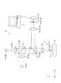
図5は、本発明の第2実施形態に係るプローブ顕微鏡1Bを示す模式図である。
前記前提技術では、プローブ顕微鏡1は、各変位検出手段は、参照ミラー6の参照面6Aにて反射された参照光と、測定光との干渉光に基づいて、変位を検出していた。これに対して、本実施形態では、プローブ顕微鏡1Bは、図5に示すように、各変位検出光学系3B,4Bを備え、各変位検出光学系3B,4Bは、前記第1実施形態における参照ミラー6に代えて、ピンホール35,45を備えている。そして、各変位検出手段は、ピンホール35,45を透過する光に基づいて、変位を検出する点で異なる。具体的に、本実施形態では、共焦点方式を採用することによって、各変位検出光学系3B,4Bは、カンチレバー2、及び被測定物Wの変位を検出する。[Second Embodiment]
Hereinafter, asecond embodiment of the present invention will be described with reference to the drawings.
FIG. 5 is a schematic diagram showing a
In the basetechnology , the probe microscope 1 detects the displacement based on the interference light between the reference light reflected by the
ピンホール35は、結像レンズ33の焦点位置に設けられ、カンチレバー2の背面、及び波長λ1に対する対物レンズ7Aの焦点位置を一致させた状態とすると、結像レンズ33にて集光される光を透過させる。
ピンホール45は、結像レンズ43の焦点位置に設けられ、被測定物Wの表面、及び波長λ2に対する対物レンズ7Aの焦点位置を一致させた状態とすると、結像レンズ43にて集光される光を透過させる。The
The
次に、変位検出光学系3Bにおける光路について説明する。
第1の光源31から射出された光は、図5に示すように、コリメータレンズ32、ビームスプリッタ51,52、及び対物レンズ7Aを介してカンチレバー2にて反射され、対物レンズ7A、及びビームスプリッタ52を介してバンドパスフィルタ53に入射する。バンドパスフィルタ53に入射した反射光は、界面531を透過して結像レンズ33に入射する。結像レンズ33に入射した反射光は、所定の位置に集光される。結像レンズ33にて集光される反射光は、ピンホール35を介して光検出素子34に入射する。光検出素子34は、PC8による制御の下、結像レンズ33にて集光される反射光を検出し、PC8は、検出された反射光の強度に基づいてカンチレバー2の変位を検出する。すなわち、第1の変位検出手段は、第1の光源31から射出され、カンチレバー2にて反射される反射光を受光することでカンチレバー2の変位を検出する。Next, the optical path in the displacement detection
As shown in FIG. 5, the light emitted from the
また、変位検出光学系4Bにおける光路について説明する。なお、被測定物Wの表面、及び波長λ2に対する対物レンズ7Aの焦点位置は一致した状態であるものとする。
第2の光源41から射出された光は、コリメータレンズ42、ビームスプリッタ51,52、及び対物レンズ7Aを介して被測定物Wにて反射され、対物レンズ7A、及びビームスプリッタ52を介してバンドパスフィルタ53に入射する。バンドパスフィルタ53に入射した反射光は、界面531にて反射され、結像レンズ43に入射する。結像レンズ43に入射した反射光は、所定の位置に集光される。結像レンズ43にて集光される反射光は、ピンホール45を介して光検出素子44に入射する。光検出素子44は、PC8による制御の下、結像レンズ43にて集光される反射光を検出し、PC8は、検出された反射光の強度に基づいて被測定物Wの変位を検出する。すなわち、第2の変位検出手段は、第2の光源41から射出され、被測定物Wにて反射される反射光を受光することで被測定物Wの変位を検出する。The optical path in the displacement detection
The light emitted from the second
図6は、カンチレバー2の探針21を被測定物Wに接触させた状態におけるプローブ顕微鏡1Bを示す模式図である。
カンチレバー2の探針21を被測定物Wに接触させた状態とすると、図6に示すように、被測定物Wの表面、及び波長λ2に対する対物レンズ7Aの焦点位置は一致せず、ピンホール45は、結像レンズ43にて集光される光を透過させることができなくなるので、第2の変位検出光学系4Bは、被測定物Wの変位を検出することができない。FIG. 6 is a schematic diagram showing the
Assuming that the
したがって、変位検出光学系3Bにてカンチレバー2の変位を検出する場合には、光検出素子34にて検出される光の強度を一定とするように、すなわちカンチレバー2の背面、及び波長λ1に対する対物レンズ7Aの焦点位置を一致させた状態とするように、被測定物WをZ軸方向に沿って移動させる。そして、変位検出光学系3Bは、被測定物Wの移動量をカンチレバー2の変位として検出する。
また、変位検出光学系4Bにて被測定物Wの変位を検出する場合には、光検出素子44にて検出される光の強度を一定とするように、すなわち被測定物Wの表面、及び波長λ2に対する対物レンズ7Aの焦点位置を一致させた状態とするように、被測定物WをZ軸方向に沿って移動させる。そして、変位検出光学系4Bは、被測定物Wの移動量を被測定物Wの変位として検出する。Therefore, when the displacement detection
Further, when detecting the displacement of the object to be measured W by the displacement detection
このような本実施形態においても、前記第1実施形態と同様の作用、効果を奏することができる。In this embodiment as well, the same operations and effects as in thefirst embodiment can be achieved.
〔第3実施形態〕
以下、本発明の第3実施形態を図面に基づいて説明する。
図7は、本発明の第3実施形態に係るプローブ顕微鏡1Cの第1の変位検出光学系3Cにおける光路を示す模式図である。図8は、プローブ顕微鏡1Cの第2の変位検出光学系4Cにおける光路を示す模式図である。[Third Embodiment]
Hereinafter, athird embodiment of the present invention will be described with reference to the drawings.
FIG. 7 is a schematic diagram showing an optical path in the first displacement detection
前記第2実施形態では、プローブ顕微鏡1Bは、各変位検出光学系3B,4Bと、共用光学系5とを備え、各変位検出光学系3B,4Bは、結像レンズ33,43と、光検出素子34,44と、ピンホール35,45とを備え、共用光学系5は、バンドパスフィルタ53を備えていた。
これに対して、本実施形態では、プローブ顕微鏡1Cは、図7、及び図8に示すように、各変位検出光学系3C,4Cと、共用光学系5Cとを備え、各変位検出光学系3C,4Cは、結像レンズとしてのアクロマートレンズ13と、光検出素子14と、ピンホール15とを備え、共用光学系5は、前記第3実施形態におけるバンドパスフィルタ53を備えていない点で異なる。なお、ピンホール15は、アクロマートレンズ13の焦点位置に設けられている。In thesecond embodiment, the
On the other hand, in this embodiment, the
変位検出光学系3Cにてカンチレバー2の変位を検出する場合には、図7に示すように、第1の光源31からのみ光を射出する。
また、変位検出光学系4Cにて被測定物Wの変位を検出する場合には、図8に示すように、第2の光源41からのみ光を射出する。When the displacement of the
When the displacement detection
このような本実施形態においても、前記第2実施形態と同様の作用、効果を奏することができる他、以下の作用、効果を奏することができる。
(4)アクロマートレンズ13は、透過する光の波長によって焦点の位置が変化しないので、各変位検出光学系3C,4Cは、第1の光源31から射出される光と、第2の光源41から射出される光とを切り替えることによって、アクロマートレンズ13(結像レンズ)、ピンホール15、及び光検出素子14を共用することができる。したがって、プローブ顕微鏡1Cの部品点数を削減することができる。In this embodiment as well, the same actions and effects as those of thesecond embodiment can be obtained, and the following actions and effects can be obtained.
(4) Since the focus position of the
〔第4実施形態〕
以下、本発明の第4実施形態を図面に基づいて説明する。
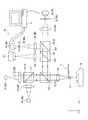
図9は、本発明の第4実施形態に係るプローブ顕微鏡1Dを示す模式図である。
本実施形態では、プローブ顕微鏡1Dは、図9に示すように、ビームスプリッタ52、及びバンドパスフィルタ53の間に配設され、バンドパスフィルタ53と同一の機能を有するバンドパスフィルタ91と、第2の光源41から射出され、被測定物Wにて反射される反射光を所定の位置に集光する結像レンズ92と、結像レンズ92にて集光される光を受光することで被測定物Wを観察する観察手段としてのカメラ93とを備えている点で前記第3実施形態と異なる。[Fourth Embodiment]
Hereinafter, afourth embodiment of the present invention will be described with reference to the drawings.
FIG. 9 is a schematic diagram showing a
In the present embodiment, as shown in FIG. 9, the probe microscope 1 </ b> D is disposed between the
具体的に、第2の光源41から射出された光は、コリメータレンズ42、ビームスプリッタ51,52、及び対物レンズ7Aを介して被測定物Wにて反射され、対物レンズ7A、及びビームスプリッタ52を介してバンドパスフィルタ91に入射する。バンドパスフィルタ91に入射した反射光は、界面911にて反射され、結像レンズ92に入射する。結像レンズ92に入射した反射光は、所定の位置に集光される。結像レンズ92にて集光される反射光は、カメラ93に入射する。カメラ93は、PC8による制御の下、結像レンズ92にて集光される反射光を検出し、検出された反射光に基づいて被測定物Wを観察する。
なお、カメラ93にて観察される像の拡大率は、対物レンズ7Aの焦点距離と、結像レンズ92の焦点距離との関係で定まる。例えば、対物レンズ7Aの焦点距離を30mmとし、結像レンズ92の焦点距離を300mmとすれば、拡大率は10倍(300mm/30mm)となる。Specifically, the light emitted from the second
The magnification of the image observed by the
このような本実施形態においても、前記第2実施形態と同様の作用、効果を奏することができる他、以下の作用、効果を奏することができる。
(5)プローブ顕微鏡1Dは、第2の変位検出光学系4Bにて被測定物Wの変位を検出するとともに、カメラ93にて結像レンズ92の焦点距離に応じた倍率で被測定物Wを拡大して観察することができる。In this embodiment as well, the same actions and effects as those of thesecond embodiment can be obtained, and the following actions and effects can be obtained.
(5) The
〔実施形態の変形〕
なお、本発明は前記各実施形態に限定されるものではなく、本発明の目的を達成できる範囲での変形、改良等は本発明に含まれるものである。また、前記各実施形態を組み合わせることは自由である。
例えば、前記第1〜2,4実施形態では、プローブ顕微鏡1,1A,1B,1Dは、バンドパスフィルタ53を備えていたが、第1の光源から射出される光と、第2の光源から射出される光とを切り替えることによって、バンドパスフィルタを省略することができる。
前記各実施形態では、第2の光源41は、−X軸方向側に配設されていたが、+X軸方向側に配設されていてもよい。なお、この場合には、ビームスプリッタ51における界面511の向きを反転させればよい。[Modification of Embodiment]
Note that the present invention is not limited to the above-described embodiments, and modifications, improvements, and the like within the scope in which the object of the present invention can be achieved are included in the present invention. Moreover, it is free to combine the embodiments.
For example, in the first, second, andfourth embodiments, the probe microscopes 1, 1 </ b> A, 1 </ b> B, and 1 </ b> D are provided with the
In the above embodiments, the second
本発明は、プローブ顕微鏡に利用でき、特に、被測定物に接触する探針を有するカンチレバーの変位を検出するための第1の変位検出光学系と、被測定物の変位を検出するための第2の変位検出光学系とを備えるプローブ顕微鏡に好適に利用することができる。 INDUSTRIAL APPLICABILITY The present invention can be used for a probe microscope, and in particular, a first displacement detection optical system for detecting the displacement of a cantilever having a probe that contacts the object to be measured and a first displacement detecting system for detecting the displacement of the object to be measured. It can utilize suitably for a probe microscope provided with 2 displacement detection optical systems.
1,1A,1B,1C,1D…プローブ顕微鏡
2…カンチレバー
3,3B,3C…第1の変位検出光学系
4,4B,4C…第2の変位検出光学系
6A…参照面
7,7A…対物レンズ
8…PC(第1の変位検出手段、及び第2の変位検出手段)
13…アクロマートレンズ
14…光検出素子(第1の変位検出手段、及び第2の変位検出手段)
15,35,45…ピンホール
21…探針
31…第1の光源
33,43,92…結像レンズ
34…光検出素子(第1の変位検出手段)
41…第2の光源
44…光検出素子(第2の変位検出手段)
93…カメラ(観察手段)DESCRIPTION OF
13 ...
15, 35, 45 ...
41... Second
93 ... Camera (observation means)
Claims (6)
Translated fromJapanese前記第1の変位検出光学系は、
前記カンチレバーに光を照射するための第1の光源と、
前記第1の光源から射出され、前記カンチレバーにて反射される反射光を受光することで前記カンチレバーの変位を検出する第1の変位検出手段とを備え、
前記第2の変位検出光学系は、
前記被測定物に前記第1の光源と異なる波長の光を照射するための第2の光源と、
前記第2の光源から射出され、前記被測定物にて反射される反射光を受光することで前記被測定物の変位を検出する第2の変位検出手段とを備え、
前記カンチレバーと、前記各光源との間に配設され、前記第1の光源から射出される光の波長に対して前記カンチレバーの位置を焦点とし、且つ、前記第2の光源から射出される光の波長に対して前記探針の先端位置より前記被測定物側の位置を焦点とする対物レンズを備え、
前記第1,2の変位検出光学系は、前記第1,2の光源からそれぞれ射出される光を前記第1,2の光源と前記対物レンズとの間で平行化し、
前記対物レンズは、前記平行化された前記第1,2の光源からの光が入射されるように、第1,2の変位検出光学系に共用される
ことを特徴とするプローブ顕微鏡。A cantilever having a probe in contact with the object to be measured; a first displacement detecting optical system for detecting displacement of the cantilever; and a second displacement detecting optical system for detecting the displacement of the object to be measured. A probe microscope for observing the surface shape of the object to be measured by scanning the surface of the object to be measured,
The first displacement detection optical system includes:
A first light source for irradiating the cantilever with light;
First displacement detection means for detecting displacement of the cantilever by receiving reflected light emitted from the first light source and reflected by the cantilever;
The second displacement detection optical system includes:
A second light source for irradiating the object to be measured with light having a wavelength different from that of the first light source;
Second displacement detection means for detecting a displacement of the object to be measured by receiving reflected light emitted from the second light source and reflected by the object to be measured;
Light disposed between the cantilever and each of the light sources, focused on the position of the cantilever with respect to the wavelength of light emitted from the first light source, and emitted from the second light source An objective lens that focuseson the position of the object to be measuredfrom the tip position of the probe with respect to the wavelength of
The first and second displacement detection optical systems collimate light respectively emitted from the first and second light sources between the first and second light sources and the objective lens,
The probeis shared by the first and second displacement detection optical systems so that light from the collimated first and second light sources is incident thereon. microscope.
前記被測定物を前記対物レンズに対して光軸方向へ移動させる手段を備える、ことを特徴とするプローブ顕微鏡。The probe microscope according to claim 1,
A probe microscope comprising: means for moving the object to be measured in the optical axis direction with respect to the objective lens.
前記各変位検出光学系は、
所定の位置に設けられ、前記各光源から射出される光を反射する参照面を備え、
前記各変位検出手段は、前記参照面にて反射される光と、前記反射光との干渉光に基づいて、変位を検出することを特徴とするプローブ顕微鏡。The probe microscope according to claim 1 or 2,
Each of the displacement detection optical systems is
A reference surface provided at a predetermined position and reflecting light emitted from each of the light sources;
Each of the displacement detection means detects a displacement based on interference light between the light reflected by the reference surface and the reflected light.
前記各変位検出光学系は、
前記反射光を所定の位置に集光する結像レンズと、
前記結像レンズにて集光される光を透過させるピンホールとを備え、
前記各変位検出手段は、前記ピンホールを透過する光に基づいて、変位を検出することを特徴とするプローブ顕微鏡。The probe microscope according to claim 1 or 2,
Each of the displacement detection optical systems is
An imaging lens for condensing the reflected light at a predetermined position;
A pinhole that transmits light collected by the imaging lens;
Each of the displacement detection means detects a displacement based on light transmitted through the pinhole.
前記結像レンズは、アクロマートレンズであることを特徴とするプローブ顕微鏡。The probe microscope according to claim 4,
2. The probe microscope according to claim 1, wherein the imaging lens is an achromatic lens.
前記第2の光源から射出され、前記被測定物にて反射される反射光を所定の位置に集光する結像レンズと、
前記結像レンズにて集光される光を受光することで前記被測定物を観察する観察手段を備えることを特徴とするプローブ顕微鏡。The probe microscope according to any one of claims 1 to 5,
An imaging lens that collects reflected light emitted from the second light source and reflected by the measurement object at a predetermined position;
A probe microscope comprising observation means for observing the object to be measured by receiving light condensed by the imaging lens.
Priority Applications (3)
| Application Number | Priority Date | Filing Date | Title |
|---|---|---|---|
| JP2009164589AJP5336959B2 (en) | 2009-07-13 | 2009-07-13 | Probe microscope |
| EP10166608.9AEP2278264B1 (en) | 2009-07-13 | 2010-06-21 | Probe microscope |
| US12/831,651US8314940B2 (en) | 2009-07-13 | 2010-07-07 | Probe microscope |
Applications Claiming Priority (1)
| Application Number | Priority Date | Filing Date | Title |
|---|---|---|---|
| JP2009164589AJP5336959B2 (en) | 2009-07-13 | 2009-07-13 | Probe microscope |
Publications (2)
| Publication Number | Publication Date |
|---|---|
| JP2011021902A JP2011021902A (en) | 2011-02-03 |
| JP5336959B2true JP5336959B2 (en) | 2013-11-06 |
Family
ID=43027491
Family Applications (1)
| Application Number | Title | Priority Date | Filing Date |
|---|---|---|---|
| JP2009164589AExpired - Fee RelatedJP5336959B2 (en) | 2009-07-13 | 2009-07-13 | Probe microscope |
Country Status (3)
| Country | Link |
|---|---|
| US (1) | US8314940B2 (en) |
| EP (1) | EP2278264B1 (en) |
| JP (1) | JP5336959B2 (en) |
Families Citing this family (4)
| Publication number | Priority date | Publication date | Assignee | Title |
|---|---|---|---|---|
| JP2010181222A (en)* | 2009-02-04 | 2010-08-19 | Mitsutoyo Corp | Probe microscope |
| KR101855816B1 (en)* | 2016-05-13 | 2018-05-10 | 주식회사 고영테크놀러지 | Biological Tissue Inspection Apparatus and Method thereof |
| KR102384026B1 (en)* | 2016-05-13 | 2022-04-07 | 주식회사 고영테크놀러지 | Biological Tissue Inspection Apparatus and Method thereof |
| DE102020118533A1 (en) | 2020-07-14 | 2022-01-20 | Bundesrepublik Deutschland, Vertreten Durch Das Bundesministerium Für Wirtschaft Und Energie, Dieses Vertreten Durch Den Präsidenten Der Physikalisch-Technischen Bundesanstalt | microscope |
Family Cites Families (10)
| Publication number | Priority date | Publication date | Assignee | Title |
|---|---|---|---|---|
| FR2626383B1 (en)* | 1988-01-27 | 1991-10-25 | Commissariat Energie Atomique | EXTENDED FIELD SCAN AND DEPTH CONFOCAL OPTICAL MICROSCOPY AND DEVICES FOR CARRYING OUT THE METHOD |
| JP3093896B2 (en)* | 1992-11-26 | 2000-10-03 | オリンパス光学工業株式会社 | Observation optical system incorporated in scanning probe microscope |
| JPH07198730A (en) | 1993-12-28 | 1995-08-01 | Hitachi Constr Mach Co Ltd | Scanning probe microscope device |
| US5756997A (en)* | 1996-03-04 | 1998-05-26 | General Nanotechnology, L.L.C. | Scanning probe/optical microscope with modular objective/probe and drive/detector units |
| JP2003067971A (en)* | 2001-08-30 | 2003-03-07 | Ricoh Co Ltd | Optical pickup device and information recording / reproducing device provided with the same |
| JP2003202284A (en)* | 2002-01-09 | 2003-07-18 | Hitachi Ltd | Scanning probe microscope, sample observation method and device manufacturing method using the same |
| US7388199B2 (en)* | 2003-09-03 | 2008-06-17 | Hitachi Kenki Fine Tech Co., Ltd. | Probe manufacturing method, probe, and scanning probe microscope |
| JP2007192637A (en)* | 2006-01-18 | 2007-08-02 | Gunma Univ | Probe microscope and probe microscope type optical recording / reproducing head device |
| JP2008224412A (en)* | 2007-03-13 | 2008-09-25 | Hitachi Kenki Fine Tech Co Ltd | Scanning probe microscope |
| JP2010181222A (en)* | 2009-02-04 | 2010-08-19 | Mitsutoyo Corp | Probe microscope |
- 2009
- 2009-07-13JPJP2009164589Apatent/JP5336959B2/ennot_activeExpired - Fee Related
- 2010
- 2010-06-21EPEP10166608.9Apatent/EP2278264B1/ennot_activeNot-in-force
- 2010-07-07USUS12/831,651patent/US8314940B2/ennot_activeExpired - Fee Related
Also Published As
| Publication number | Publication date |
|---|---|
| US8314940B2 (en) | 2012-11-20 |
| EP2278264B1 (en) | 2014-06-25 |
| EP2278264A1 (en) | 2011-01-26 |
| US20110007324A1 (en) | 2011-01-13 |
| JP2011021902A (en) | 2011-02-03 |
Similar Documents
| Publication | Publication Date | Title |
|---|---|---|
| US9891418B2 (en) | Apparatus for imaging a sample surface | |
| US9804029B2 (en) | Microspectroscopy device | |
| US7477401B2 (en) | Trench measurement system employing a chromatic confocal height sensor and a microscope | |
| JP5966982B2 (en) | Confocal measuring device | |
| JP5712342B2 (en) | Optical microscope and spectrum measuring method | |
| US8829402B2 (en) | Autofocusing device for microscopes and suitable autofocus aperture stops | |
| KR102115498B1 (en) | Confocal measurement device | |
| JP4888807B2 (en) | Scanning shape measuring machine | |
| JP2015504178A (en) | Measuring device | |
| WO2012074805A1 (en) | Systems and methods for multi-wavelength spr biosensing with reduced chromatic aberration | |
| JP4962134B2 (en) | Measuring device | |
| JP5336959B2 (en) | Probe microscope | |
| JP4601266B2 (en) | Laser microscope | |
| JP5356804B2 (en) | Raman scattered light measurement system | |
| JP4223349B2 (en) | Vibration-resistant interferometer device | |
| CN214011030U (en) | Multi-mode microscopic hyperspectral imager | |
| CN113959366A (en) | Method and device for multi-wavelength single-fiber confocal microscopy detection | |
| US8108942B2 (en) | Probe microscope | |
| EP3751327B1 (en) | Method of and apparatus for monitoring a focus state of a microscope | |
| JP2010197089A (en) | Interferometer | |
| JP2020071414A (en) | Measuring device for collimation adjustment and method for adjusting collimation optical system | |
| JP2010181782A (en) | Automatic focusing device | |
| JP2011209294A (en) | Probe microscope | |
| JP2017181182A (en) | Spectrometer | |
| JP2011227317A (en) | Optical element and focus detector |
Legal Events
| Date | Code | Title | Description |
|---|---|---|---|
| A621 | Written request for application examination | Free format text:JAPANESE INTERMEDIATE CODE: A621 Effective date:20120606 | |
| A977 | Report on retrieval | Free format text:JAPANESE INTERMEDIATE CODE: A971007 Effective date:20121108 | |
| A131 | Notification of reasons for refusal | Free format text:JAPANESE INTERMEDIATE CODE: A131 Effective date:20121120 | |
| A521 | Request for written amendment filed | Free format text:JAPANESE INTERMEDIATE CODE: A523 Effective date:20130117 | |
| A02 | Decision of refusal | Free format text:JAPANESE INTERMEDIATE CODE: A02 Effective date:20130312 | |
| A521 | Request for written amendment filed | Free format text:JAPANESE INTERMEDIATE CODE: A523 Effective date:20130611 | |
| A911 | Transfer to examiner for re-examination before appeal (zenchi) | Free format text:JAPANESE INTERMEDIATE CODE: A911 Effective date:20130618 | |
| TRDD | Decision of grant or rejection written | ||
| A01 | Written decision to grant a patent or to grant a registration (utility model) | Free format text:JAPANESE INTERMEDIATE CODE: A01 Effective date:20130730 | |
| A61 | First payment of annual fees (during grant procedure) | Free format text:JAPANESE INTERMEDIATE CODE: A61 Effective date:20130802 | |
| R150 | Certificate of patent or registration of utility model | Ref document number:5336959 Country of ref document:JP Free format text:JAPANESE INTERMEDIATE CODE: R150 Free format text:JAPANESE INTERMEDIATE CODE: R150 | |
| R250 | Receipt of annual fees | Free format text:JAPANESE INTERMEDIATE CODE: R250 | |
| R250 | Receipt of annual fees | Free format text:JAPANESE INTERMEDIATE CODE: R250 | |
| LAPS | Cancellation because of no payment of annual fees |