JP5331307B2 - Capsule endoscope and capsule endoscope system - Google Patents
Capsule endoscope and capsule endoscope systemDownload PDFInfo
- Publication number
- JP5331307B2 JP5331307B2JP2007014171AJP2007014171AJP5331307B2JP 5331307 B2JP5331307 B2JP 5331307B2JP 2007014171 AJP2007014171 AJP 2007014171AJP 2007014171 AJP2007014171 AJP 2007014171AJP 5331307 B2JP5331307 B2JP 5331307B2
- Authority
- JP
- Japan
- Prior art keywords
- power
- capsule endoscope
- power receiving
- antenna
- core
- Prior art date
- Legal status (The legal status is an assumption and is not a legal conclusion. Google has not performed a legal analysis and makes no representation as to the accuracy of the status listed.)
- Expired - Fee Related
Links
- 239000002775capsuleSubstances0.000titleclaimsdescription77
- 230000005540biological transmissionEffects0.000claimsdescription48
- 230000005291magnetic effectEffects0.000description50
- 230000004907fluxEffects0.000description34
- 238000004804windingMethods0.000description18
- 238000003384imaging methodMethods0.000description14
- 230000004048modificationEffects0.000description10
- 238000012986modificationMethods0.000description10
- 238000012545processingMethods0.000description7
- 238000010586diagramMethods0.000description6
- 230000003287optical effectEffects0.000description6
- 238000000034methodMethods0.000description5
- 238000006243chemical reactionMethods0.000description3
- 238000004891communicationMethods0.000description3
- 239000000470constituentSubstances0.000description3
- 230000000694effectsEffects0.000description3
- 230000006872improvementEffects0.000description3
- 239000000758substrateSubstances0.000description3
- 239000003990capacitorSubstances0.000description2
- 230000008859changeEffects0.000description2
- 230000001276controlling effectEffects0.000description2
- 230000007423decreaseEffects0.000description2
- 239000000696magnetic materialSubstances0.000description2
- 239000000463materialSubstances0.000description2
- 230000004044responseEffects0.000description2
- 230000009747swallowingEffects0.000description2
- 238000012795verificationMethods0.000description2
- 241000255925DipteraSpecies0.000description1
- 239000000956alloySubstances0.000description1
- 230000003247decreasing effectEffects0.000description1
- 238000004146energy storageMethods0.000description1
- 239000003302ferromagnetic materialSubstances0.000description1
- 238000009499grossingMethods0.000description1
- 238000005286illuminationMethods0.000description1
- 238000007689inspectionMethods0.000description1
- 229910001092metal group alloyInorganic materials0.000description1
- 210000004798organs belonging to the digestive systemAnatomy0.000description1
- 230000002572peristaltic effectEffects0.000description1
- 230000035699permeabilityEffects0.000description1
- 230000010287polarizationEffects0.000description1
- 230000008569processEffects0.000description1
- 230000001105regulatory effectEffects0.000description1
- 229920006395saturated elastomerPolymers0.000description1
- 229910000859α-FeInorganic materials0.000description1
Images


Classifications
- A—HUMAN NECESSITIES
- A61—MEDICAL OR VETERINARY SCIENCE; HYGIENE
- A61B—DIAGNOSIS; SURGERY; IDENTIFICATION
- A61B1/00—Instruments for performing medical examinations of the interior of cavities or tubes of the body by visual or photographical inspection, e.g. endoscopes; Illuminating arrangements therefor
- A61B1/04—Instruments for performing medical examinations of the interior of cavities or tubes of the body by visual or photographical inspection, e.g. endoscopes; Illuminating arrangements therefor combined with photographic or television appliances
- A61B1/041—Capsule endoscopes for imaging
- A—HUMAN NECESSITIES
- A61—MEDICAL OR VETERINARY SCIENCE; HYGIENE
- A61B—DIAGNOSIS; SURGERY; IDENTIFICATION
- A61B1/00—Instruments for performing medical examinations of the interior of cavities or tubes of the body by visual or photographical inspection, e.g. endoscopes; Illuminating arrangements therefor
- A61B1/00002—Operational features of endoscopes
- A61B1/00011—Operational features of endoscopes characterised by signal transmission
- A61B1/00016—Operational features of endoscopes characterised by signal transmission using wireless means
- A—HUMAN NECESSITIES
- A61—MEDICAL OR VETERINARY SCIENCE; HYGIENE
- A61B—DIAGNOSIS; SURGERY; IDENTIFICATION
- A61B1/00—Instruments for performing medical examinations of the interior of cavities or tubes of the body by visual or photographical inspection, e.g. endoscopes; Illuminating arrangements therefor
- A61B1/00002—Operational features of endoscopes
- A61B1/00025—Operational features of endoscopes characterised by power management
- A61B1/00027—Operational features of endoscopes characterised by power management characterised by power supply
- A61B1/00029—Operational features of endoscopes characterised by power management characterised by power supply externally powered, e.g. wireless
- H—ELECTRICITY
- H02—GENERATION; CONVERSION OR DISTRIBUTION OF ELECTRIC POWER
- H02J—CIRCUIT ARRANGEMENTS OR SYSTEMS FOR SUPPLYING OR DISTRIBUTING ELECTRIC POWER; SYSTEMS FOR STORING ELECTRIC ENERGY
- H02J50/00—Circuit arrangements or systems for wireless supply or distribution of electric power
- H02J50/10—Circuit arrangements or systems for wireless supply or distribution of electric power using inductive coupling
- H—ELECTRICITY
- H02—GENERATION; CONVERSION OR DISTRIBUTION OF ELECTRIC POWER
- H02J—CIRCUIT ARRANGEMENTS OR SYSTEMS FOR SUPPLYING OR DISTRIBUTING ELECTRIC POWER; SYSTEMS FOR STORING ELECTRIC ENERGY
- H02J50/00—Circuit arrangements or systems for wireless supply or distribution of electric power
- H02J50/40—Circuit arrangements or systems for wireless supply or distribution of electric power using two or more transmitting or receiving devices
- H02J50/402—Circuit arrangements or systems for wireless supply or distribution of electric power using two or more transmitting or receiving devices the two or more transmitting or the two or more receiving devices being integrated in the same unit, e.g. power mats with several coils or antennas with several sub-antennas
- A—HUMAN NECESSITIES
- A61—MEDICAL OR VETERINARY SCIENCE; HYGIENE
- A61B—DIAGNOSIS; SURGERY; IDENTIFICATION
- A61B1/00—Instruments for performing medical examinations of the interior of cavities or tubes of the body by visual or photographical inspection, e.g. endoscopes; Illuminating arrangements therefor
- A61B1/06—Instruments for performing medical examinations of the interior of cavities or tubes of the body by visual or photographical inspection, e.g. endoscopes; Illuminating arrangements therefor with illuminating arrangements
- A61B1/0661—Endoscope light sources
- A61B1/0684—Endoscope light sources using light emitting diodes [LED]
- A—HUMAN NECESSITIES
- A61—MEDICAL OR VETERINARY SCIENCE; HYGIENE
- A61B—DIAGNOSIS; SURGERY; IDENTIFICATION
- A61B2560/00—Constructional details of operational features of apparatus; Accessories for medical measuring apparatus
- A61B2560/02—Operational features
- A61B2560/0204—Operational features of power management
- A61B2560/0214—Operational features of power management of power generation or supply
- A61B2560/0219—Operational features of power management of power generation or supply of externally powered implanted units
- A—HUMAN NECESSITIES
- A61—MEDICAL OR VETERINARY SCIENCE; HYGIENE
- A61B—DIAGNOSIS; SURGERY; IDENTIFICATION
- A61B5/00—Measuring for diagnostic purposes; Identification of persons
- A61B5/07—Endoradiosondes
- A61B5/073—Intestinal transmitters
- H—ELECTRICITY
- H02—GENERATION; CONVERSION OR DISTRIBUTION OF ELECTRIC POWER
- H02J—CIRCUIT ARRANGEMENTS OR SYSTEMS FOR SUPPLYING OR DISTRIBUTING ELECTRIC POWER; SYSTEMS FOR STORING ELECTRIC ENERGY
- H02J2310/00—The network for supplying or distributing electric power characterised by its spatial reach or by the load
- H02J2310/10—The network having a local or delimited stationary reach
- H02J2310/20—The network being internal to a load
- H02J2310/23—The load being a medical device, a medical implant, or a life supporting device
Landscapes
- Engineering & Computer Science (AREA)
- Health & Medical Sciences (AREA)
- Life Sciences & Earth Sciences (AREA)
- Surgery (AREA)
- Computer Networks & Wireless Communication (AREA)
- Biophysics (AREA)
- Molecular Biology (AREA)
- Optics & Photonics (AREA)
- Pathology (AREA)
- Radiology & Medical Imaging (AREA)
- Physics & Mathematics (AREA)
- Biomedical Technology (AREA)
- Heart & Thoracic Surgery (AREA)
- Medical Informatics (AREA)
- Nuclear Medicine, Radiotherapy & Molecular Imaging (AREA)
- Animal Behavior & Ethology (AREA)
- General Health & Medical Sciences (AREA)
- Public Health (AREA)
- Veterinary Medicine (AREA)
- Power Engineering (AREA)
- Endoscopes (AREA)
- Measurement Of The Respiration, Hearing Ability, Form, And Blood Characteristics Of Living Organisms (AREA)
Description
Translated fromJapanese本発明は、外部からの磁界を受けて電力に変換する受電アンテナを具備したカプセル内視鏡、及びカプセル内視鏡システムに関する。The present inventionwas mosquito capsule endoscope comprising a power receiving antenna is converted into electric power by receiving a magnetic field from the outside, and a capsule endoscope system.
近年、体腔内等の検査等を行うための医療用システムとして、例えばカプセル形状の筐体の内部に撮像光学系からなる観察手段、及び撮像手段からなる照明手段、通信手段、電源、受電手段等を収納した小型の内規鏡である、いわゆるカプセル内視鏡が開発されている。このカプセル内視鏡は、無線通信を行う通信装置、受信した信号を記録する記録手段、体外から交流磁界を用いて無線等により電気エネルギを供給する無線給電システムと共にカプセル内視鏡システムを構成する。このようなカプセル内視鏡システムは、例えば特許文献1によって開示されている。 In recent years, as a medical system for performing an inspection of a body cavity or the like, for example, an observing unit including an imaging optical system inside a capsule-shaped housing, an illuminating unit including the imaging unit, a communication unit, a power source, a power receiving unit, etc. A so-called capsule endoscope has been developed which is a small-sized internal mirror that accommodates the lens. This capsule endoscope constitutes a capsule endoscope system together with a communication device that performs wireless communication, a recording unit that records a received signal, and a wireless power feeding system that supplies electric energy wirelessly using an AC magnetic field from outside the body. . Such a capsule endoscope system is disclosed in
このような従来のカプセル内視鏡システムは、内蔵される受電アンテナがカプセル内視鏡の内壁を取り巻く形態でコイル状に形成されている。 In such a conventional capsule endoscope system, a built-in power receiving antenna is formed in a coil shape so as to surround the inner wall of the capsule endoscope.
このような構成により無線給電システムの送電アンテナから送電される電気エネルギは、カプセル内視鏡の受電アンテナによって受電されることで、体外に配される無線給電システムから体腔内で使用中のカプセル内視鏡へと給電されるようになっている。
ところが、従来のカプセル内視鏡は、例えば被検者が嚥下等により、その体腔内に導入されて使用されるものである。そして、被検体の体腔内に挿入された後のカプセル内視鏡は、消化器官の蠕動運動等により体腔内を移動するようになっている。 However, the conventional capsule endoscope is used by being introduced into a body cavity of a subject, for example, by swallowing. Then, the capsule endoscope after being inserted into the body cavity of the subject moves in the body cavity by the peristaltic motion of the digestive organs.
したがって、体腔内に押入されて使用状態にあるカプセル内視鏡は、被検体の体腔内において、その姿勢が常に一定にあるとは限らず様々な方向を向くことになる。このために、カプセル内視鏡の内部に配設される受電コイルの巻き軸の向きと無線給電システムの送電アンテナから発生する磁束の向きとは常に一致した状態にあるとは限らない。 Therefore, the capsule endoscope that is pushed into the body cavity and is in use is not always constant in the body cavity of the subject, and is directed in various directions. For this reason, the direction of the winding axis of the power receiving coil disposed inside the capsule endoscope and the direction of the magnetic flux generated from the power transmission antenna of the wireless power feeding system are not always in a consistent state.
したがって、カプセル内視鏡の受電コイルの巻き軸の向きと無線給電システムの送電アンテナから発生する磁束の向きとが一致しない場合には、受電コイルの巻き軸方向に対して鎖交する磁束数が減少することになり、受電効率が低下してしまうという問題点がある。 Therefore, when the direction of the winding axis of the power receiving coil of the capsule endoscope does not match the direction of the magnetic flux generated from the power transmission antenna of the wireless power feeding system, the number of magnetic fluxes linked to the direction of the winding axis of the power receiving coil is As a result, the power receiving efficiency is lowered.
例えば、送電アンテナから発生する磁束の向きと受電コイルの巻き軸の向きとのなす角がと45°となると送電アンテナから発生する磁束の向きと受電コイルの巻き軸の向きが一致している場合と比較して受電電力は、およそ1/2となってしまう。また、このことから、姿勢が不安定な状態で移動するカプセル内視鏡に対して常に充分な電力を供給し続けるためには、巻き軸の向きと磁束の向きが一致しない場合にも十分な受電が可能になる様に、大きな送電電力が必要になる。 For example, when the angle between the direction of the magnetic flux generated from the power transmission antenna and the direction of the winding axis of the power receiving coil is 45 °, the direction of the magnetic flux generated from the power transmission antenna matches the direction of the winding axis of the power receiving coil The received power is approximately ½ compared to. In addition, from this, in order to always supply sufficient power to the capsule endoscope that moves in an unstable posture, it is sufficient even when the direction of the winding axis and the direction of the magnetic flux do not match. A large amount of transmitted power is required so that power can be received.
そこで、本発明は、上述の事情に鑑みてなされたものであって、カプセル内視鏡、及びカプセル内視鏡システムの受電アンテナを大きくすることなく、受電効率を向上させ、カプセル内視鏡、及びカプセル内視鏡システムの省エネルギ化を目的とする。Therefore, the present invention has been made in view of the above circumstances, and without increasing the power receiving antenna of thecapsule endoscope and the capsule endoscope system , improves the power receiving efficiency, And it aims at the energy-saving of acapsule endoscope system .
上記目的を達成すべく、本発明の一態様のカプセル内視鏡は、無線で電力を受電するために、長さが直径に対して10倍以上の略棒状のコア部材の外周に受電コイルが巻回された複数の受電アンテナを内蔵するカプセル内視鏡において、上記複数の受電アンテナは、上記コア部材の長軸が平行に、且つ正多角形の頂点に夫々配置されている。In order to achieve the above object, in order to receive power wirelessly, the capsule endoscope of one embodiment of the present invention has a receiving coil on the outer periphery of a substantially rod-shaped core member whose length is 10 times or more the diameter. In the capsule endoscopeincluding aplurality of wound power receiving antennas, theplurality of power receiving antennas are respectivelyarranged in parallel with the major axis of the core memberand at the apex of a regular polygon .
さらに、本発明の一態様のカプセル内視鏡システムは、無線で電源からの電力を送電する送電アンテナを備えた送電システムと、送電された該電力を受電するために、長さが直径に対して10倍以上の略棒状のコア部材の外周に受電コイルが巻回された複数の受電アンテナが内蔵されたカプセル内視鏡と、を具備し、上記複数の受電アンテナは、上記コア部材の長軸が平行に、且つ正多角形の頂点に夫々配置されている。Further, a capsule endoscope system according to one embodiment of the present invention includes a power transmission system including a power transmission antenna that wirelessly transmits power from a power source, and a length that is smaller than a diameter in order to receive the transmitted power. A capsule endoscopeincluding a plurality of power receiving antennaseach having a power receiving coil wound around an outer periphery of a substantially rod-shaped core member having a size of 10 times or more, and theplurality of power receiving antennas have a length of the core member. The axes arearranged in paralleland at the vertices of the regular polygon .
本発明によれば、無線給電システムから無線送電される電気エネルギを効率的に受電し得る構成を実現し、受電効率の向上に寄与するカプセル内視鏡、及びカプセル内視鏡システムを提供することができる。According to the present invention, to realize a configuration capable of receiving an electrical energy wirelessly transmitting from the wireless power feeding system efficient, providesLuca capsule endoscope to contribute to the improvement of the power reception efficiency, and the capsule endoscope system can do.
以下、図面を参照して本発明の実施の形態を説明する。尚、以下に示す実施の形態において無線給電システムは、カプセル内視鏡を例に挙げて説明する。 Embodiments of the present invention will be described below with reference to the drawings. In the embodiment described below, the wireless power feeding system will be described by taking a capsule endoscope as an example.
(第1の実施の形態)
先ず、本発明の第1の実施の形態について説明する。図1〜図9は、第1の実施の形態に係り、図1はカプセル内視鏡システムの構成を示すと共に、カプセル内視鏡が被検体の体腔内に導入された状態を示す図、図2は受電アンテナを備えたカプセル内視鏡の断面図、図3は図2のIII−III線に沿ったカプセル内視鏡を円筒方向の正面から見た断面図、図4はカプセル内視鏡と送電システムを示すブロック図、図5は受電アンテナのコア内部を通過する磁束を説明するための図、図6は受電アンテナの構成を示す図、図7はコアのアスペクト比を変化させたときのある一定の磁界中でのアスペクト比と受電電力の関係を示した表、図8は図7の結果を転記したアスペクト比と受電電力の関係を示したグラフ、図9は変形例の受電アンテナの構成を示す図である。(First embodiment)
First, a first embodiment of the present invention will be described. 1 to 9 relate to the first embodiment, and FIG. 1 is a diagram showing a configuration of a capsule endoscope system and a state in which the capsule endoscope is introduced into a body cavity of a subject. 2 is a cross-sectional view of a capsule endoscope provided with a power receiving antenna, FIG. 3 is a cross-sectional view of the capsule endoscope taken along line III-III in FIG. 2 as viewed from the front in the cylindrical direction, and FIG. 4 is a capsule endoscope. FIG. 5 is a diagram for explaining the magnetic flux passing through the core of the power receiving antenna, FIG. 6 is a diagram showing the configuration of the power receiving antenna, and FIG. 7 is a diagram when the aspect ratio of the core is changed. 8 is a table showing the relationship between the aspect ratio and the received power in a certain magnetic field, FIG. 8 is a graph showing the relationship between the aspect ratio and the received power in which the result of FIG. 7 is transcribed, and FIG. 9 is a modified receiving antenna. FIG.
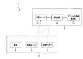
図1に示すように、本実施の形態のカプセル内視鏡システム1は、無線給電システムを構成している、送電システム2とカプセル内視鏡3によって構成されている。 As shown in FIG. 1, the
送電システム2は、体外に設けられ、送電装置本体4と、無線によって電気エネルギを送電するための送電アンテナ5とによって構成されている。この送電装置本体4は、夫々が電気的に接続された、電源6と、制御回路7と、駆動回路8とが内蔵されている。尚、本実施の形態において、制御回路7、及び駆動回路8は、制御ユニット9を構成している。 The power transmission system 2 is provided outside the body and includes a power transmission device main body 4 and a
この制御ユニット9は、電源6の出力を制御することによって、送電アンテナ5の出力を制御し、送電アンテナ5から発生する交流磁界、すなわち送電電力を調節するようになっている。 The control unit 9 controls the output of the
送電アンテナ5は、ヘルムホルツ型コイルである2つの円環状のアンテナ部5a,5bにより構成され、夫々のアンテナ部5a,5bが送電装置本体4の駆動回路8と電気的に接続されている。これらアンテナ部5a,5bは、被検者100の胴体部に所定の距離で離間するように装着される。 The
このように構成された送電システム2は、電源6および制御回路7によって生成された交流電流を送電アンテナ5に印加する。交流電流が印加された送電アンテナ5は、印加された交流電流の大きさに応じた交流磁界を発生し、被検者の体内等に、ここではアンテナ部5bからアンテナ部5aへの磁束Mを発生させる。尚、送電アンテナ5は、ヘルムホルツ型コイルに限らず、ソレノイド型コイル、若しくは他のコイルであっても勿論構わない。 The power transmission system 2 configured as described above applies an alternating current generated by the power source 6 and the control circuit 7 to the
図1に示すカプセル内視鏡3は、被検者によって嚥下される等により体腔内に導入されるものであり、外観形状がカプセル型の錠剤形状を有している。 A
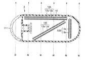
このカプセル内視鏡3は、図2に示すように、両端がドーム状の略カプセル型の外部筐体10と、この外部筐体10の一端に配設された透明カバー11とによって、密閉されている。この外部筐体10の内部には、受電アンテナ12と、受電回路13と、カプセル内視鏡機能部14と、が内蔵されている。 As shown in FIG. 2, the
受電アンテナ12は、強磁性体で円柱形状からなる細長いコア12aと、このコア12aの外周に沿って巻回された受電コイル12bと、から構成されている。受電コイル12bは、コア12a全体に均一に巻かれている。なお、コア12aの形状は、略棒状の円柱形状に限られることはなく、柱状形態をしていれば、断面形状が四角形状や八角形状等の多角形状であってもよい。また、円筒形状のような環状形状でもよい。 The
コア12aを構成する材料は、金属合金系材料、フェライト系材料、及びアモルファス系磁性材料等の高透磁率磁性材料である。このコア12aは、図3からも判るように、外部筐体10の内周近傍に配置され、長尺な棒形状をしている。 The material constituting the
受電回路13は、受電アンテナ12が受電した電力への変換に、カプセル内視鏡内に交流電流を整流するダイオードブリッジなどの整流回路、エネルギ蓄積要素、リップル減衰要素として機能するキャパシタ等の平滑回路等が設けられている。これらは、一般に用いられる回路であるため、ここでは説明および図示ともに省略する。 The
また、外部から印加される交流磁界の周波数と共振するよう、受電アンテナ12には共振用キャパシタが接続されているが、これについても図示を省略する。 In addition, a resonance capacitor is connected to the
カプセル内視鏡機能部14は、照明手段である照明用発光ダイオード(LED)15、及び照明光により照射された部位からの反射光を受けて光学像を形成し、後述の撮像素子の受光面上に被写体像を結像させる撮像光学系であるレンズ群16aを備えたレンズ枠16と、光学的な被写体像を受けて電気的な信号に変換する光電変換処理を行う光電変換素子であるCMOS、CCDなどのイメージセンサ等からなる撮像素子15と、この撮像素子15の駆動制御を行う撮像素子駆動部17と、信号処理部18と、受電アンテナ12に接続される受電回路部19と、非常用バッテリ20と、撮影した画像を外部へ送信する送信アンテナ21を備えた撮像素子15から出力される電気信号(画像信号)を受けて所定の信号を変調し増幅するための変調送信アンプ部22と、を有し、これらが硬質基板、或いはFPCの電気基板25上に所定に配置されて構成される。 The capsule endoscope
上記撮像素子15は、LED15により照射された部位を撮像する機能を有している。この撮像素子15、及びレンズ群16aを含む撮像光学系、撮像素子駆動部17等によって撮像手段が構成されている。つまり、この撮像手段は、体腔内の様子を画像表示装置の観察画面上に観察画像として表示するための電気的な画像信号を取得する機能を有するものである。 The
また、変調送信アンプ部22、送信アンテナ21等は、上記撮像手段により取得された画像信号を体外に設置される送電システム2の受信手段へと送信する送信手段を構成している。この送信手段は、信号処理部18によって信号処理された画像信号を受けて所定の信号処理を施した後、その処理済みの画像信号を外部に向けて送信する機能を有している。 Further, the modulation
以上のように構成される本実施形態のカプセル内視鏡システム1において、上記カプセル内視鏡3の撮像手段の撮像動作により取得された画像信号は、信号処理部18によってデータ化された後、送信手段(変調送信アンプ部22及び送信アンテナ21)を介して送電システム2へと送信される。これを受けて、送電システム2は画像データ信号を受信する。 In the
送電システム2が受信した画像データ信号は、内部の回路において所定の信号処理が施された後、画像表示装置(不図示)へと伝送され、表示するのに最適な形態の画像信号とするための所定の信号処理が施された後、画像表示装置の表示部に画像として表示される。 The image data signal received by the power transmission system 2 is subjected to predetermined signal processing in an internal circuit, and then transmitted to an image display device (not shown) to obtain an image signal in an optimum form for display. After the predetermined signal processing is performed, the image is displayed as an image on the display unit of the image display device.
一方、送電システム2は、図4に示すように、制御ユニット9による電源6の制御に基づいて送電アンテナ5から無線給電方式によって電気エネルギを送電する。カプセル内視鏡3の受電アンテナ12は、送電アンテナ5からの電気エネルギを受電して受電回路13へと伝送する。 On the other hand, as shown in FIG. 4, the power transmission system 2 transmits electrical energy from the
ここで、受電アンテナ12が電気エネルギを受電する際に発生する反磁界について、図5を用いて説明する。
反磁界とは、磁性体内部に生じる磁界のことで、例えば図5に示すように、送電アンテナ5から発生したコア12aによって集められた磁束Mは、コア12aの内部を通過する。磁束Mが通過したコア12aは、長手方向に磁気分極をし、内部に磁束Maが通過する方向とは反対方向の磁界、すなわち反磁界を生じ、その反磁界により、磁束Mbが磁束Maとは反対方向に生じる。そのため、受電コイル12bと鎖交する有効磁束Maは、反磁界による磁束Mbの影響で、コア12aによって集められた磁束Mよりも減少することになる。Here, a demagnetizing field generated when the
The demagnetizing field is a magnetic field generated inside the magnetic body. As shown in FIG. 5, for example, the magnetic flux M collected by the
この反磁界は、磁気分極が大きいほど、また磁極間距離が短いほど大きくなる。すなわち、反磁界は、コア12aの直径が大きいほど、またコア12aの長さが短いほど大きくなり、アスペクト比(コア12aの長さ/コア12aの直径)に依存している。 The demagnetizing field increases as the magnetic polarization increases and the distance between the magnetic poles decreases. That is, the demagnetizing field increases as the diameter of the
次に、受電アンテナ12のコア12aの長さと直径の値に依存するアスペクト比の変化と受電電力の変動の関係について説明する。
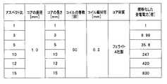
図6に示すように、受電アンテナ12のコア12aの直径dを一定に保ち、コア12aの長軸方向の長さLを変化せることで得られるアスペクト比(L/d)の変化による受電電力の変動を、図7の表に示し、その結果を図8のグラフに転記する。Next, the relationship between the change in the aspect ratio depending on the length and diameter values of the core 12a of the
As shown in FIG. 6, the received power by changing the aspect ratio (L / d) obtained by keeping the diameter d of the core 12a of the
なお、図7、及び図8では、コア12aのアスペクト比を1とした時の受電電力を1として、各アスペクト比の受電電力を記した。図7の表に示すように、コア12aの直径dを1mmとし、長さLを変化させたフェライトコア(A社製)に受電コイル12bをコア全体に均一に50回巻いた受電アンテナ12を一様な磁場中に配置したときの受電電力の変化を検証してみた。また、一様な磁場の向きと受電コイル12bの巻き軸、及びコア12aの長軸との向きは一致、つまり、平行(なす角0°)にしている。 7 and 8, the received power when the aspect ratio of the
図7、及び図8に示す検証結果より、受電電力はアスペクト比が10以上になると急激に受電電力が増大する事が分かった。アスペクト比を10以上に設定することにより、コア12a内部の反磁界は小さくなり、反磁界による磁束Mbが減少することによって有効磁束Maは増加し、受電電力は増加する。 From the verification results shown in FIG. 7 and FIG. 8, it was found that the received power increases rapidly when the aspect ratio becomes 10 or more. By setting the aspect ratio to 10 or more, the demagnetizing field inside the
つまり、アスペクト比を10以上とすると、反磁界は大きく減少し、受電電力はアスペクト比が1の場合と比較すると247倍以上となる。そのため、例えばアスペクト比10とした導合には、送電アンテナ5から発生する磁束Mの向きと受電コイルとの巻き軸とのなす角が45°となっても規格化した受電電力は理論的に半分(1/2)の123.5(247/2)倍となり、充分に大きな電力となる。このアスペクト比10とした受電アンテナ12は、送電アンテナ5から発生する磁束Mの向きと受電コイル12bとの巻き軸、及びコア12aの長軸とのなす角が一致(0°)するときのアスペクト比が5のコア12aを用いた受電アンテナ12の場合よりもはるかに大きな受電電力を得られる。 That is, when the aspect ratio is 10 or more, the demagnetizing field is greatly reduced, and the received power is 247 times or more as compared with the case where the aspect ratio is 1. Therefore, for example, when the aspect ratio is 10, the normalized received power is theoretically even when the angle between the direction of the magnetic flux M generated from the
よって、送電アンテナ5から発生する磁束Mの向きと、受電コイル12bの巻き軸、及びアスペクト比を10以上とするコア12aの長軸とのなす角が大きくなってもカプセル内視鏡3を駆動させるために必要な電力が供給可能に設定することができる。なお、検証結果では、印加する一様な磁場の大きさ、周波数は一定として行ったが、一様な磁場の大きさや周波数を変化させてもコア12aが磁気飽和しない限り、規格化した受電電力は同じであることがわかった。 Therefore, the
以上説明したように本実施の形態によれば、受電アンテナ12のコア12aを細長くしアスペクト比を10以上に増大させたことにより反磁界の影響が小さくなり、受電コイル12bと鎮交する有効磁束Maを増加させることが可能となる。 As described above, according to the present embodiment, the effect of the demagnetizing field is reduced by elongating the
これにより、受電アンテナ12の受電効率を向上させ、かつ安定した電力を供給することができる。また、受電効率が向上することで、従来の受電アンテナの場合と比較して、送電アンテナ5から発生される磁束Mの向きと、アスペクト比を10以上とするコア12aの長軸、及び受電コイル12bの巻き軸とのなす角が大きくなっても、カプセル内視鏡3を駆動させることが可能となる。 Thereby, the power receiving efficiency of the
なお、以下に受電コイルの巻き方を説明する。反磁界の影響はコア12aの端部よりも中心部の方が小さい事が分かっている。この事より、受電コイル12bの巻き方に関しては、巻き数が同じ場合、図9のように、反磁界の影響の小さいコア12a中心部にコイルを密に巻く方が、コア12a全体に均一に巻くよりも受電効率が更に上昇する事になる。 In addition, how to wind up a receiving coil is demonstrated below. It has been found that the influence of the demagnetizing field is smaller at the center than at the end of the
尚、本実施の形態のカプセル内視鏡3は、受電アンテナ12によるカプセル内視鏡機能部14を電気的に駆動するために必要な電力が得られない場合には、非常用バッテリ20により、電力供給補助が行われる。この受電アンテナ12によるカプセル内視鏡機能部14を電気的に駆動するために必要な電力が得られない場合とは、送電アンテナ5から発生される磁束Mの向きと、アスペクト比を10以上とするコア12aの長軸、及び受電コイル12bの巻き軸とのなす角が90°のときをいう。 Note that the
(第2の実施の形態)
次に、本発明の第2の実施の形態について説明する。また、図10〜図13は、第2の実施の形態に係り、図10は1つの無線給電システムにおける複数の受電アンテナを示す図、図11は第1の変形例のカプセル内視鏡の横断面図、図12は第2の変形例のカプセル内視鏡の横断面図、図13は第3の変形例のカプセル内視鏡の縦断面図である。(Second Embodiment)
Next, a second embodiment of the present invention will be described. 10 to 13 relate to the second embodiment, FIG. 10 is a diagram showing a plurality of power receiving antennas in one wireless power feeding system, and FIG. 11 is a crossing of the capsule endoscope of the first modified example. FIG. 12 is a cross-sectional view of the capsule endoscope of the second modified example, and FIG. 13 is a longitudinal sectional view of the capsule endoscope of the third modified example.
尚、以下の説明において、上述した第1の実施の形態のカプセル内視鏡システム1と同一の構成について同じ符号を用い、それら構成の詳細な説明を省略する。また、図面の簡略化のため、カプセル内視鏡が有する、既知の光源、撮像光学系、撮像素子、電子制御部品等のその他の各構成部品は図示していないものがある。 In the following description, the same components as those in the
本実施形態の基本的な構成は、上述の第1の実施の形態と略同様であって、図10に示すように受電アンテナ12を複数配設し、それらを直列または並列に接続する点のみ異なる。なお、受電コイルの巻数および巻き方は図5と同一である。 The basic configuration of the present embodiment is substantially the same as that of the first embodiment described above, and only a plurality of
まず、第1の実施の形態と同様に本実施の形態では、送電アンテナ5から発生した磁束Mは受電コイル12bと鎖交する。本実施の形態では、複数の受電アンテナ12を配設しているため、受電アンテナ12が単数の場合と比較して、鎮交磁束Mを増加させることができる。また、従来技術では受電効率を向上させるためには、カプセル内視鏡3を大径化する必要があったが、本実施形態ではカプセル内視鏡3の直径を大きくすることなく、受電アンテナ12を複数配設する。したがって、カプセル内視鏡3を大径化することなく、受電アンテナ12の受電効率を、第1の実施の形態と比べてさらに向上させることができ、カプセル内視鏡3をより安定に駆動することができる。 First, in the present embodiment as in the first embodiment, the magnetic flux M generated from the
本実施の形態においては、図10に示すように各受電アンテナ12は隣接して配設した例を示している。しかしながら、各々の受電アンテナ12を一定距離で離して配設してもよい。 In the present embodiment, as shown in FIG. 10, the
例えば、図11に示すように第1の変形例は2つの受電アンテナ12同士の距離をカプセル内視鏡3内で最も離間する距離が長くなるように配設したものである。同様に、図12に示す第2の変形例は3つの受電アンテナ12を正三角形の頂点上に配設した例である。 For example, as shown in FIG. 11, the first modification is arranged such that the distance between the two
第1、及び第2の変形例では、各々の受電アンテナ12を隣接して配設した場合と比べて、複数の受電アンテナ12の相互インダクタンスを最小とすることができる。そのため、受電アンテナ12の更なる受電効率の向上が期待できる。 In the first and second modifications, the mutual inductance of the plurality of
また、第2の変形例では受電アンテナ12を3つとしたが、複数であれば幾つでもよく、係る場合に複数のアンテナを、正多角形の頂点上に配設すれば、各々の受電アンテナ12との相互インダクタンスが最小となるため、更なる受電効率の向上を期待できる。 In the second modification, the number of
第1および第2の変形例では、各々の受電アンテナ12の長軸は同じ方向、つまり平行であったが、図13に示す第3の変形例は、各々のコア12aの長軸、及び受電コイル12bの巻き軸を異なる方向になるように3つ配設した形態を示す。 In the first and second modified examples, the major axis of each
この場合には、1つの受電アンテナ12の長軸と送電アンテナ5から発生される磁束Mとのなす角が90°となる電力を受電できなくなる状態においても、他の受電アンテナ12の長軸と送電アンテナ5から発生される磁束Mとのなす角が90°とはならない。そのため、カプセル内視鏡3が被検者100の体腔内で如何なる姿勢となっても、安定した電力を受電することが可能となる。 In this case, the long axis of the other
例えば、図13の矢印の方向に磁束Mが通過するとき、3つのうち、この磁束Mになす角が90°の1つの受電アンテナ12Aは、受電電力が得られない。しかし、受電アンテナ12Bは、磁束Mと長軸が一致(並行)している。また、もう1つの受電アンテナ12Cは、長尺でアスペクト比が大きく設定できるため、磁束Mと長軸とのなす角が大きくなっても十分な受電電力を得られる。これらのため、カプセル内視鏡3を駆動するための十分な電力を受電することができる。 For example, when the magnetic flux M passes in the direction of the arrow in FIG. 13, among the three
なお、以上の説明では受電アンテナ12の個数を3つとして行ったが、複数であればいくつでもよく、受電アンテナ12のコア12aのアスペクト比、受電コイル12bの巻数、巻き方などは、各々に設定することができる。また、受電アンテナ12の向きは配設する複数の受電アンテナ12のうち、少なくとも1つが異なる方向であればよい。 In the above description, the number of
上述の第1及び第2実施形態およびその変形形態においては、本発明の無線給電システムをカプセル内視鏡システム1に適用した場合の例で説明したが、この例に限ることはなく、本発明の無線給電システムは、無線給電方式によって、電力を送受信する装置に対して広く適用し得ることは言うまでもない。 In the above-described first and second embodiments and modifications thereof, an example in which the wireless power feeding system of the present invention is applied to the
以上の各実施の形態に記載した発明は、夫々の実施の形態に限ることなく、その他、実施段階ではその要旨を逸脱しない範囲で種々の変形を実施し得ることが可能である。さらに、上記各実施形態には、種々の段階の発明が含まれており、開示される複数の構成要件における適宜な組合せにより種々の発明が抽出され得る。 The invention described in each of the above embodiments is not limited to each embodiment, and various modifications can be made without departing from the scope of the invention in the implementation stage. Further, the above embodiments include inventions at various stages, and various inventions can be extracted by appropriately combining a plurality of disclosed constituent elements.
例えば、各実施形態に示される全構成要件から幾つかの構成要件が削除されても、発明が解決しようとする課題の欄で述べた課題が解決でき、発明の効果で述べられている効果が得られる場合には、この構成要件が削除された構成が発明として抽出され得る。 For example, even if some constituent elements are deleted from all the constituent elements shown in each embodiment, the problems described in the column of problems to be solved by the invention can be solved, and the effects described in the effects of the invention can be achieved. In the case of being obtained, a configuration from which this configuration requirement is deleted can be extracted as an invention.
1・・・カプセル内視鏡システム
2・・・送電システム
3・・・カプセル内視鏡
4・・・送電装置本体
5・・・送電アンテナ
6・・・電源
7・・・制御回路
8・・・駆動回路
9・・・制御ユニット
10・・・外部筐体
11・・・透明カバー
12・・・受電アンテナ
12a・・・コア
12b・・・受電コイル
13・・・受電回路
14・・・カプセル内視鏡機能部
15・・・撮像素子
17・・・撮像素子駆動部
18・・・信号処理部
19・・・受電回路部
20・・・非常用バッテリ
21・・・送信アンテナ
22・・・変調送信アンプ部
25・・・電気基板
M・・・磁束DESCRIPTION OF
Claims (2)
Translated fromJapanese上記複数の受電アンテナは、上記コア部材の長軸が平行に、且つ正多角形の頂点に夫々配置されていることを特徴とするカプセル内視鏡。In order to receive power wirelessly, in a capsule endoscopeincluding aplurality of power receiving antennas in which a power receiving coil is wound around the outer periphery of a substantially rod-shaped core member whose length is 10 times or more the diameter,
The capsule endoscope, wherein theplurality of power receiving antennas arearranged such that major axes of the core members are parallel toeach other and apexes of a regular polygon .
送電された該電力を受電するために、長さが直径に対して10倍以上の略棒状のコア部材の外周に受電コイルが巻回された複数の受電アンテナが内蔵されたカプセル内視鏡と、
を具備し、
上記複数の受電アンテナは、上記コア部材の長軸が平行に、且つ正多角形の頂点に夫々配置されていることを特徴とするカプセル内視鏡システム。A power transmission system including a power transmission antenna that wirelessly transmits power from a power source;
A capsule endoscopeincluding aplurality of power receiving antennaseach having a power receiving coil wound around an outer periphery of a substantially rod-shaped core member having a length of 10 times or more the diameter to receive the transmitted power; ,
Comprising
The capsule endoscope system, wherein theplurality of power receiving antennas arearranged such that major axes of the core members are parallel toeach other and apexes of a regular polygon .
Priority Applications (4)
| Application Number | Priority Date | Filing Date | Title |
|---|---|---|---|
| JP2007014171AJP5331307B2 (en) | 2007-01-24 | 2007-01-24 | Capsule endoscope and capsule endoscope system |
| EP08150500AEP1952753B1 (en) | 2007-01-24 | 2008-01-22 | Wireless power supply system, capsulated endoscope, and capsulated endoscopic system |
| DE602008002443TDE602008002443D1 (en) | 2007-01-24 | 2008-01-22 | Wireless power supply system, encapsulated endoscope and encapsulated endoscopic system |
| US12/018,603US8591403B2 (en) | 2007-01-24 | 2008-01-23 | Wireless power supply system, capsulated endoscope, and capsulated endoscopic system |
Applications Claiming Priority (1)
| Application Number | Priority Date | Filing Date | Title |
|---|---|---|---|
| JP2007014171AJP5331307B2 (en) | 2007-01-24 | 2007-01-24 | Capsule endoscope and capsule endoscope system |
Publications (2)
| Publication Number | Publication Date |
|---|---|
| JP2008178545A JP2008178545A (en) | 2008-08-07 |
| JP5331307B2true JP5331307B2 (en) | 2013-10-30 |
Family
ID=39493872
Family Applications (1)
| Application Number | Title | Priority Date | Filing Date |
|---|---|---|---|
| JP2007014171AExpired - Fee RelatedJP5331307B2 (en) | 2007-01-24 | 2007-01-24 | Capsule endoscope and capsule endoscope system |
Country Status (4)
| Country | Link |
|---|---|
| US (1) | US8591403B2 (en) |
| EP (1) | EP1952753B1 (en) |
| JP (1) | JP5331307B2 (en) |
| DE (1) | DE602008002443D1 (en) |
Families Citing this family (21)
| Publication number | Priority date | Publication date | Assignee | Title |
|---|---|---|---|---|
| US9510740B2 (en) | 2002-03-12 | 2016-12-06 | Karl Storz Endovision, Inc. | Auto recognition of a shaver blade for medical use |
| US8723936B2 (en) | 2002-03-12 | 2014-05-13 | Karl Storz Imaging, Inc. | Wireless camera coupling with rotatable coupling |
| US20120123508A1 (en)* | 2010-11-12 | 2012-05-17 | Massachusetts Institute Of Technology | Methods and apparatus for wireless control of biological tissue |
| US9295378B2 (en)* | 2008-02-04 | 2016-03-29 | University Hospitals Of Cleveland | Universal handle |
| US9603512B2 (en)* | 2008-04-25 | 2017-03-28 | Karl Storz Imaging, Inc. | Wirelessly powered medical devices and instruments |
| EP2347698A4 (en)* | 2008-11-18 | 2013-10-16 | Olympus Corp | Encapsulated medical device, power supply device, and power supply system |
| JP5627067B2 (en)* | 2008-12-01 | 2014-11-19 | オリンパス株式会社 | Living body observation system and driving method of the living body observation system |
| JP5820645B2 (en)* | 2011-07-11 | 2015-11-24 | オリンパス株式会社 | Biological information acquisition system |
| WO2013098016A1 (en) | 2011-12-29 | 2013-07-04 | Arcelik Anonim Sirketi | Wireless kitchen appliance operated on an induction heating cooker |
| CN104137648B (en)* | 2011-12-29 | 2017-06-27 | 阿塞里克股份有限公司 | The wireless kitchen utensils operated on induction heating cooker |
| US20150141752A1 (en)* | 2012-05-19 | 2015-05-21 | Capso Vision, Inc. | Optical Wireless Docking System for Capsule Camera |
| JP2014023774A (en)* | 2012-07-27 | 2014-02-06 | Olympus Corp | Biological information acquisition system |
| US10045713B2 (en) | 2012-08-16 | 2018-08-14 | Rock West Medical Devices, Llc | System and methods for triggering a radiofrequency transceiver in the human body |
| KR102094803B1 (en)* | 2013-07-22 | 2020-03-31 | 한국과학기술원 | Power Collecting Apparatus for Stabilizing Voltage Collection |
| EP3060102B1 (en) | 2013-10-22 | 2021-03-24 | Rock West Medical Devices, LLC | System to localize swallowable pill sensor with three transmitting elements |
| JP6600955B2 (en)* | 2015-03-20 | 2019-11-06 | カシオ計算機株式会社 | Electronics |
| JP6595232B2 (en) | 2015-07-02 | 2019-10-23 | ソニー・オリンパスメディカルソリューションズ株式会社 | Endoscope imaging apparatus, endoscope apparatus, and endoscope cable |
| CA3046620A1 (en)* | 2016-09-01 | 2018-03-08 | Sanjaya Maniktala | Segmented and longitudinal receiver coil arrangements for wireless power transfer |
| US10251580B2 (en)* | 2017-02-01 | 2019-04-09 | Rock West Medical Devices, Llc | Flexible circuit for a swallowable pill |
| CA3054004A1 (en) | 2017-03-07 | 2018-09-13 | University Of Southampton | Intra-uterine monitoring system |
| GB2590924A (en)* | 2020-01-06 | 2021-07-14 | Creo Medical Ltd | A receiver for wirelessly receiving power from a transmitter, a capsule for ingestion by a patient, and a wireless power transfer system |
Family Cites Families (37)
| Publication number | Priority date | Publication date | Assignee | Title |
|---|---|---|---|---|
| US3742341A (en)* | 1971-08-16 | 1973-06-26 | Entex Ind Inc | Inductively coupled metal detector arrangement |
| JPS57131042U (en)* | 1981-02-12 | 1982-08-16 | ||
| JPH07169627A (en)* | 1993-12-15 | 1995-07-04 | Mitsubishi Electric Corp | Non-contact transformer |
| JPH1013270A (en)* | 1996-06-27 | 1998-01-16 | Sony Corp | Radio receiver and its charging device |
| US5741316A (en)* | 1996-12-02 | 1998-04-21 | Light Sciences Limited Partnership | Electromagnetic coil configurations for power transmission through tissue |
| US6201387B1 (en)* | 1997-10-07 | 2001-03-13 | Biosense, Inc. | Miniaturized position sensor having photolithographic coils for tracking a medical probe |
| US8636648B2 (en)* | 1999-03-01 | 2014-01-28 | West View Research, Llc | Endoscopic smart probe |
| US6273904B1 (en)* | 1999-03-02 | 2001-08-14 | Light Sciences Corporation | Polymer battery for internal light device |
| JP4338280B2 (en) | 2000-02-15 | 2009-10-07 | Hoya株式会社 | Capsule endoscope |
| US20020165592A1 (en)* | 2001-04-04 | 2002-11-07 | Arkady Glukhovsky | Induction powered in vivo imaging device |
| US7286868B2 (en)* | 2001-06-15 | 2007-10-23 | Biosense Inc. | Medical device with position sensor having accuracy at high temperatures |
| US6664938B2 (en)* | 2002-03-01 | 2003-12-16 | Ems Technologies Canada, Ltd. | Pentagonal helical antenna array |
| JP3827151B2 (en)* | 2002-03-07 | 2006-09-27 | Necトーキン株式会社 | Non-contact power receiving element |
| US7808236B1 (en)* | 2002-12-09 | 2010-10-05 | Ferro Solutions, Inc. | Energy harvester utilizing external magnetic field |
| JP2005052637A (en)* | 2003-07-18 | 2005-03-03 | Pentax Corp | Capsule type device and capsule type device drive control system |
| DE102004034444A1 (en)* | 2003-07-18 | 2005-02-03 | Pentax Corp. | Endoscope capsule for digestive tract investigations has power coupling coils at different angles to provide stable output and orientation information |
| JP2005062161A (en)* | 2003-07-25 | 2005-03-10 | Seiko Epson Corp | Electronic clock with built-in antenna |
| JP2005077361A (en)* | 2003-09-03 | 2005-03-24 | Seiko Epson Corp | Electronic clock with built-in antenna |
| EP1681010B1 (en)* | 2003-10-27 | 2012-10-10 | Olympus Corporation | Capsule type medical device |
| JP4426875B2 (en)* | 2004-03-08 | 2010-03-03 | オリンパス株式会社 | Capsule medical device magnetic guidance system |
| US7751866B2 (en) | 2004-03-08 | 2010-07-06 | Olympus Corporation | Detecting system of position and posture of capsule medical device |
| JP2006118925A (en)* | 2004-10-20 | 2006-05-11 | Seiko Epson Corp | Electronic watch with wireless function and control method thereof, and external charging device for electronic watch with wireless function |
| JP4624768B2 (en)* | 2004-11-29 | 2011-02-02 | オリンパス株式会社 | Intra-subject introduction apparatus and intra-subject introduction system |
| JP2006306184A (en)* | 2005-04-27 | 2006-11-09 | Denso Corp | Wheel side antenna device, and tire condition detecting device having the same |
| US7825543B2 (en)* | 2005-07-12 | 2010-11-02 | Massachusetts Institute Of Technology | Wireless energy transfer |
| JP2007082816A (en)* | 2005-09-22 | 2007-04-05 | Hitachi Metals Ltd | Electronic device member, capsule type endoscope and medical system |
| US7957789B2 (en)* | 2005-12-30 | 2011-06-07 | Medtronic, Inc. | Therapy delivery system including a navigation element |
| JP3933191B1 (en)* | 2006-03-13 | 2007-06-20 | 株式会社村田製作所 | Portable electronic devices |
| DE102006019987A1 (en)* | 2006-04-26 | 2007-10-31 | Siemens Ag | Endoscopic capsule for investigation of body openings, has induction coil with elongation along one axis, and magnetic element having magnetic dipole moment aligned perpendicular to longitudinal axis of induction coil |
| JP4890953B2 (en)* | 2006-06-13 | 2012-03-07 | オリンパス株式会社 | Capsule endoscope system |
| GB2457824B (en)* | 2006-09-19 | 2010-12-08 | Hydro Technologies Inc | Magnetic communication through metal barriers |
| US8378523B2 (en)* | 2007-03-02 | 2013-02-19 | Qualcomm Incorporated | Transmitters and receivers for wireless energy transfer |
| US20090273242A1 (en)* | 2008-05-05 | 2009-11-05 | Nigelpower, Llc | Wireless Delivery of power to a Fixed-Geometry power part |
| US8317970B2 (en)* | 2008-06-03 | 2012-11-27 | Applied Materials, Inc. | Ceiling electrode with process gas dispersers housing plural inductive RF power applicators extending into the plasma |
| US8253278B2 (en)* | 2008-06-05 | 2012-08-28 | Qualcomm Incorporated | Ferrite antennas for wireless power transfer |
| US8497601B2 (en)* | 2008-09-27 | 2013-07-30 | Witricity Corporation | Wireless energy transfer converters |
| US8810194B2 (en)* | 2008-11-20 | 2014-08-19 | Qualcomm Incorporated | Retrofitting wireless power and near-field communication in electronic devices |
- 2007
- 2007-01-24JPJP2007014171Apatent/JP5331307B2/ennot_activeExpired - Fee Related
- 2008
- 2008-01-22EPEP08150500Apatent/EP1952753B1/ennot_activeNot-in-force
- 2008-01-22DEDE602008002443Tpatent/DE602008002443D1/enactiveActive
- 2008-01-23USUS12/018,603patent/US8591403B2/enactiveActive
Also Published As
| Publication number | Publication date |
|---|---|
| DE602008002443D1 (en) | 2010-10-28 |
| US20080177143A1 (en) | 2008-07-24 |
| EP1952753B1 (en) | 2010-09-15 |
| US8591403B2 (en) | 2013-11-26 |
| JP2008178545A (en) | 2008-08-07 |
| EP1952753A1 (en) | 2008-08-06 |
Similar Documents
| Publication | Publication Date | Title |
|---|---|---|
| JP5331307B2 (en) | Capsule endoscope and capsule endoscope system | |
| JP4890953B2 (en) | Capsule endoscope system | |
| US7604591B2 (en) | Capsule medical apparatus | |
| JP2008178544A (en) | Wireless feeding system, capsule endoscope and capsule endoscope system | |
| JP4414725B2 (en) | Capsule medical device | |
| US12191566B2 (en) | Compact helix antenna for in-vivo devices | |
| WO2016098818A1 (en) | Capsule endoscope, capsule endoscopic inspection method, and capsule endoscopic inspection device | |
| JP2004528890A5 (en) | ||
| JP4624768B2 (en) | Intra-subject introduction apparatus and intra-subject introduction system | |
| US10502947B2 (en) | Optical fiber scanning apparatus and optical scanning type endoscope | |
| JP4520130B2 (en) | Capsule medical device | |
| JP2010110432A (en) | Wireless type intra-subject information acquisition apparatus | |
| Ryu et al. | Three-dimensional power receiver for in vivo robotic capsules | |
| JP2017124026A (en) | Capsule-type endoscope and drive system of capsule-type endoscope | |
| US20100164484A1 (en) | Position detection system and position detection method | |
| JP2009148552A (en) | Radio observation device and endoscope system | |
| JP2010115363A (en) | Radio power feeder | |
| JP5415744B2 (en) | Capsule medical device | |
| JP2007301177A (en) | Wireless power receiving apparatus | |
| CN103401322B (en) | Wireless energy receiving coil for gastrointestinal tract indagation microsystem | |
| KR102019229B1 (en) | Method and apparatus for activating and deactivating a capsule endoscope | |
| JP4370121B2 (en) | Endoscope device | |
| WO2016098402A1 (en) | Capsule endoscope and capsule endoscope system | |
| JP2006149685A (en) | In-subject introduction device and in-subject introduction system | |
| JP2010094184A (en) | Coil and coil apparatus using the coil |
Legal Events
| Date | Code | Title | Description |
|---|---|---|---|
| A621 | Written request for application examination | Free format text:JAPANESE INTERMEDIATE CODE: A621 Effective date:20091126 | |
| A977 | Report on retrieval | Free format text:JAPANESE INTERMEDIATE CODE: A971007 Effective date:20120130 | |
| A131 | Notification of reasons for refusal | Free format text:JAPANESE INTERMEDIATE CODE: A131 Effective date:20120327 | |
| A521 | Request for written amendment filed | Free format text:JAPANESE INTERMEDIATE CODE: A523 Effective date:20120528 | |
| A131 | Notification of reasons for refusal | Free format text:JAPANESE INTERMEDIATE CODE: A131 Effective date:20120612 | |
| A521 | Request for written amendment filed | Free format text:JAPANESE INTERMEDIATE CODE: A523 Effective date:20120813 | |
| A131 | Notification of reasons for refusal | Free format text:JAPANESE INTERMEDIATE CODE: A131 Effective date:20130507 | |
| A521 | Request for written amendment filed | Free format text:JAPANESE INTERMEDIATE CODE: A523 Effective date:20130626 | |
| TRDD | Decision of grant or rejection written | ||
| A01 | Written decision to grant a patent or to grant a registration (utility model) | Free format text:JAPANESE INTERMEDIATE CODE: A01 Effective date:20130716 | |
| A61 | First payment of annual fees (during grant procedure) | Free format text:JAPANESE INTERMEDIATE CODE: A61 Effective date:20130729 | |
| R151 | Written notification of patent or utility model registration | Ref document number:5331307 Country of ref document:JP Free format text:JAPANESE INTERMEDIATE CODE: R151 | |
| S531 | Written request for registration of change of domicile | Free format text:JAPANESE INTERMEDIATE CODE: R313531 | |
| R350 | Written notification of registration of transfer | Free format text:JAPANESE INTERMEDIATE CODE: R350 | |
| R250 | Receipt of annual fees | Free format text:JAPANESE INTERMEDIATE CODE: R250 | |
| R250 | Receipt of annual fees | Free format text:JAPANESE INTERMEDIATE CODE: R250 | |
| R250 | Receipt of annual fees | Free format text:JAPANESE INTERMEDIATE CODE: R250 | |
| R250 | Receipt of annual fees | Free format text:JAPANESE INTERMEDIATE CODE: R250 | |
| R250 | Receipt of annual fees | Free format text:JAPANESE INTERMEDIATE CODE: R250 | |
| LAPS | Cancellation because of no payment of annual fees |