JP5331282B2 - Sapphire reinforced thermocouple protection tube - Google Patents
Sapphire reinforced thermocouple protection tubeDownload PDFInfo
- Publication number
- JP5331282B2 JP5331282B2JP2001530543AJP2001530543AJP5331282B2JP 5331282 B2JP5331282 B2JP 5331282B2JP 2001530543 AJP2001530543 AJP 2001530543AJP 2001530543 AJP2001530543 AJP 2001530543AJP 5331282 B2JP5331282 B2JP 5331282B2
- Authority
- JP
- Japan
- Prior art keywords
- thermocouple
- sapphire
- protective tube
- tube
- side protective
- Prior art date
- Legal status (The legal status is an assumption and is not a legal conclusion. Google has not performed a legal analysis and makes no representation as to the accuracy of the status listed.)
- Expired - Lifetime
Links
- 239000010980sapphireSubstances0.000titleclaimsdescription107
- 229910052594sapphireInorganic materials0.000titleclaimsdescription107
- 230000001681protective effectEffects0.000claimsdescription154
- 238000002309gasificationMethods0.000claimsdescription37
- 238000000034methodMethods0.000claimsdescription31
- 230000008569processEffects0.000claimsdescription25
- 239000002131composite materialSubstances0.000claimsdescription15
- BASFCYQUMIYNBI-UHFFFAOYSA-NplatinumChemical compound[Pt]BASFCYQUMIYNBI-UHFFFAOYSA-N0.000claimsdescription15
- 239000000835fiberSubstances0.000claimsdescription14
- 239000000203mixtureSubstances0.000claimsdescription11
- PNEYBMLMFCGWSK-UHFFFAOYSA-Naluminium oxideInorganic materials[O-2].[O-2].[O-2].[Al+3].[Al+3]PNEYBMLMFCGWSK-UHFFFAOYSA-N0.000claimsdescription9
- 229910052751metalInorganic materials0.000claimsdescription9
- 239000002184metalSubstances0.000claimsdescription9
- 229910052703rhodiumInorganic materials0.000claimsdescription7
- 239000010948rhodiumSubstances0.000claimsdescription7
- MHOVAHRLVXNVSD-UHFFFAOYSA-Nrhodium atomChemical compound[Rh]MHOVAHRLVXNVSD-UHFFFAOYSA-N0.000claimsdescription7
- 229910052697platinumInorganic materials0.000claimsdescription6
- 230000003287optical effectEffects0.000claimsdescription5
- 238000009529body temperature measurementMethods0.000claimsdescription4
- 239000011208reinforced composite materialSubstances0.000claimsdescription2
- 239000007789gasSubstances0.000description35
- 238000005728strengtheningMethods0.000description28
- 239000002893slagSubstances0.000description20
- 229930195733hydrocarbonNatural products0.000description11
- 150000002430hydrocarbonsChemical class0.000description11
- 239000004215Carbon black (E152)Substances0.000description9
- 239000007788liquidSubstances0.000description9
- 230000003647oxidationEffects0.000description9
- 238000007254oxidation reactionMethods0.000description9
- OKTJSMMVPCPJKN-UHFFFAOYSA-NCarbonChemical compound[C]OKTJSMMVPCPJKN-UHFFFAOYSA-N0.000description8
- 229910052799carbonInorganic materials0.000description8
- 239000000919ceramicSubstances0.000description8
- 239000003921oilSubstances0.000description8
- 239000007787solidSubstances0.000description8
- 239000000446fuelSubstances0.000description7
- 239000000463materialSubstances0.000description7
- 230000003628erosive effectEffects0.000description6
- 238000006243chemical reactionMethods0.000description5
- 238000001816coolingMethods0.000description5
- 229910052593corundumInorganic materials0.000description5
- 239000010431corundumSubstances0.000description5
- 230000006378damageEffects0.000description5
- 229910052760oxygenInorganic materials0.000description5
- 230000035939shockEffects0.000description5
- 239000000126substanceSubstances0.000description5
- XEEYBQQBJWHFJM-UHFFFAOYSA-NIronChemical compound[Fe]XEEYBQQBJWHFJM-UHFFFAOYSA-N0.000description4
- 239000003245coalSubstances0.000description4
- VNWKTOKETHGBQD-UHFFFAOYSA-NmethaneChemical compoundCVNWKTOKETHGBQD-UHFFFAOYSA-N0.000description4
- 229910018072Al 2 O 3Inorganic materials0.000description3
- UHOVQNZJYSORNB-UHFFFAOYSA-NBenzeneChemical compoundC1=CC=CC=C1UHOVQNZJYSORNB-UHFFFAOYSA-N0.000description3
- 229910000831SteelInorganic materials0.000description3
- YXFVVABEGXRONW-UHFFFAOYSA-NTolueneChemical compoundCC1=CC=CC=C1YXFVVABEGXRONW-UHFFFAOYSA-N0.000description3
- 230000009471actionEffects0.000description3
- QVGXLLKOCUKJST-UHFFFAOYSA-Natomic oxygenChemical compound[O]QVGXLLKOCUKJST-UHFFFAOYSA-N0.000description3
- 229910002091carbon monoxideInorganic materials0.000description3
- 239000003638chemical reducing agentSubstances0.000description3
- 229910052739hydrogenInorganic materials0.000description3
- CPLXHLVBOLITMK-UHFFFAOYSA-Nmagnesium oxideInorganic materials[Mg]=OCPLXHLVBOLITMK-UHFFFAOYSA-N0.000description3
- 150000002739metalsChemical class0.000description3
- OFBQJSOFQDEBGM-UHFFFAOYSA-Nn-pentaneNatural productsCCCCCOFBQJSOFQDEBGM-UHFFFAOYSA-N0.000description3
- 239000001301oxygenSubstances0.000description3
- 239000010959steelSubstances0.000description3
- OYPRJOBELJOOCE-UHFFFAOYSA-NCalciumChemical compound[Ca]OYPRJOBELJOOCE-UHFFFAOYSA-N0.000description2
- VYZAMTAEIAYCRO-UHFFFAOYSA-NChromiumChemical group[Cr]VYZAMTAEIAYCRO-UHFFFAOYSA-N0.000description2
- UFWIBTONFRDIAS-UHFFFAOYSA-NNaphthaleneChemical compoundC1=CC=CC2=CC=CC=C21UFWIBTONFRDIAS-UHFFFAOYSA-N0.000description2
- ATUOYWHBWRKTHZ-UHFFFAOYSA-NPropaneChemical compoundCCCATUOYWHBWRKTHZ-UHFFFAOYSA-N0.000description2
- 229910004298SiO 2Inorganic materials0.000description2
- 230000008901benefitEffects0.000description2
- 229910052791calciumInorganic materials0.000description2
- 239000011575calciumSubstances0.000description2
- 239000013626chemical specieSubstances0.000description2
- 229910052804chromiumInorganic materials0.000description2
- 239000011651chromiumSubstances0.000description2
- 239000000571cokeSubstances0.000description2
- 239000000356contaminantSubstances0.000description2
- 230000007797corrosionEffects0.000description2
- 238000005260corrosionMethods0.000description2
- 230000000694effectsEffects0.000description2
- 238000010292electrical insulationMethods0.000description2
- 125000002534ethynyl groupChemical group[H]C#C*0.000description2
- HYBBIBNJHNGZAN-UHFFFAOYSA-NfurfuralChemical compoundO=CC1=CC=CO1HYBBIBNJHNGZAN-UHFFFAOYSA-N0.000description2
- 239000011810insulating materialSubstances0.000description2
- 229910052742ironInorganic materials0.000description2
- 239000000395magnesium oxideSubstances0.000description2
- 238000004519manufacturing processMethods0.000description2
- 238000005259measurementMethods0.000description2
- 229910044991metal oxideInorganic materials0.000description2
- 150000004706metal oxidesChemical class0.000description2
- 239000000615nonconductorSubstances0.000description2
- 239000011368organic materialSubstances0.000description2
- 239000002245particleSubstances0.000description2
- 239000011819refractory materialSubstances0.000description2
- 230000002787reinforcementEffects0.000description2
- 230000003014reinforcing effectEffects0.000description2
- 239000002002slurrySubstances0.000description2
- 229910001220stainless steelInorganic materials0.000description2
- 239000010935stainless steelSubstances0.000description2
- 230000035882stressEffects0.000description2
- XTQHKBHJIVJGKJ-UHFFFAOYSA-Nsulfur monoxideChemical classS=OXTQHKBHJIVJGKJ-UHFFFAOYSA-N0.000description2
- 239000002699waste materialSubstances0.000description2
- XLYOFNOQVPJJNP-UHFFFAOYSA-NwaterChemical compoundOXLYOFNOQVPJJNP-UHFFFAOYSA-N0.000description2
- OTMSDBZUPAUEDD-UHFFFAOYSA-NEthaneChemical compoundCCOTMSDBZUPAUEDD-UHFFFAOYSA-N0.000description1
- VGGSQFUCUMXWEO-UHFFFAOYSA-NEtheneChemical compoundC=CVGGSQFUCUMXWEO-UHFFFAOYSA-N0.000description1
- 239000005977EthyleneSubstances0.000description1
- UFHFLCQGNIYNRP-UHFFFAOYSA-NHydrogenChemical compound[H][H]UFHFLCQGNIYNRP-UHFFFAOYSA-N0.000description1
- CTQNGGLPUBDAKN-UHFFFAOYSA-NO-XyleneChemical compoundCC1=CC=CC=C1CCTQNGGLPUBDAKN-UHFFFAOYSA-N0.000description1
- 102100026827Protein associated with UVRAG as autophagy enhancerHuman genes0.000description1
- 101710102978Protein associated with UVRAG as autophagy enhancerProteins0.000description1
- 239000002253acidSubstances0.000description1
- 150000001298alcoholsChemical class0.000description1
- 150000001299aldehydesChemical class0.000description1
- 150000001336alkenesChemical class0.000description1
- HSFWRNGVRCDJHI-UHFFFAOYSA-Nalpha-acetyleneNatural productsC#CHSFWRNGVRCDJHI-UHFFFAOYSA-N0.000description1
- RHZUVFJBSILHOK-UHFFFAOYSA-Nanthracen-1-ylmethanolateChemical compoundC1=CC=C2C=C3C(C[O-])=CC=CC3=CC2=C1RHZUVFJBSILHOK-UHFFFAOYSA-N0.000description1
- 239000003830anthraciteSubstances0.000description1
- 150000001491aromatic compoundsChemical class0.000description1
- 150000004945aromatic hydrocarbonsChemical class0.000description1
- 239000010426asphaltSubstances0.000description1
- 230000004888barrier functionEffects0.000description1
- 230000003796beautyEffects0.000description1
- 230000009286beneficial effectEffects0.000description1
- 239000002802bituminous coalSubstances0.000description1
- 239000001273butaneSubstances0.000description1
- 239000006227byproductSubstances0.000description1
- 150000001720carbohydratesChemical class0.000description1
- 235000014633carbohydratesNutrition0.000description1
- 239000003575carbonaceous materialSubstances0.000description1
- 239000003518causticsSubstances0.000description1
- 239000004568cementSubstances0.000description1
- 238000001311chemical methods and processMethods0.000description1
- 239000011280coal tarSubstances0.000description1
- 230000008602contractionEffects0.000description1
- 238000005336crackingMethods0.000description1
- 239000010779crude oilSubstances0.000description1
- 230000007423decreaseEffects0.000description1
- 230000007547defectEffects0.000description1
- 238000011161developmentMethods0.000description1
- 238000011143downstream manufacturingMethods0.000description1
- 239000003344environmental pollutantSubstances0.000description1
- 239000012530fluidSubstances0.000description1
- 238000004231fluid catalytic crackingMethods0.000description1
- 239000002737fuel gasSubstances0.000description1
- 239000000295fuel oilSubstances0.000description1
- 239000003502gasolineSubstances0.000description1
- 238000010438heat treatmentMethods0.000description1
- 239000001257hydrogenSubstances0.000description1
- 230000006872improvementEffects0.000description1
- 229910052500inorganic mineralInorganic materials0.000description1
- 239000003350keroseneSubstances0.000description1
- 150000002576ketonesChemical class0.000description1
- 239000003077ligniteSubstances0.000description1
- 239000003915liquefied petroleum gasSubstances0.000description1
- 230000013011matingEffects0.000description1
- 239000011707mineralSubstances0.000description1
- 238000000465mouldingMethods0.000description1
- IJDNQMDRQITEOD-UHFFFAOYSA-Nn-butaneChemical compoundCCCCIJDNQMDRQITEOD-UHFFFAOYSA-N0.000description1
- -1naphthaSubstances0.000description1
- 239000003345natural gasSubstances0.000description1
- 239000004058oil shaleSubstances0.000description1
- 239000013307optical fiberSubstances0.000description1
- 150000007524organic acidsChemical class0.000description1
- 235000005985organic acidsNutrition0.000description1
- 230000001590oxidative effectEffects0.000description1
- 238000004806packaging method and processMethods0.000description1
- 239000003415peatSubstances0.000description1
- 239000002006petroleum cokeSubstances0.000description1
- 239000003209petroleum derivativeSubstances0.000description1
- 239000011295pitchSubstances0.000description1
- 231100000719pollutantToxicity0.000description1
- 238000004886process controlMethods0.000description1
- 238000012545processingMethods0.000description1
- 239000000047productSubstances0.000description1
- 239000001294propaneSubstances0.000description1
- 239000011253protective coatingSubstances0.000description1
- 238000005086pumpingMethods0.000description1
- 238000000746purificationMethods0.000description1
- 230000035484reaction timeEffects0.000description1
- 239000011226reinforced ceramicSubstances0.000description1
- 239000004576sandSubstances0.000description1
- 239000010865sewageSubstances0.000description1
- 239000003079shale oilSubstances0.000description1
- 230000008054signal transmissionEffects0.000description1
- 239000007962solid dispersionSubstances0.000description1
- 239000004071sootSubstances0.000description1
- 239000003476subbituminous coalSubstances0.000description1
- 239000011269tarSubstances0.000description1
- 239000011275tar sandSubstances0.000description1
- 230000008646thermal stressEffects0.000description1
- 238000012546transferMethods0.000description1
- 238000005406washingMethods0.000description1
- 239000008096xyleneSubstances0.000description1
Images


Classifications
- G—PHYSICS
- G01—MEASURING; TESTING
- G01K—MEASURING TEMPERATURE; MEASURING QUANTITY OF HEAT; THERMALLY-SENSITIVE ELEMENTS NOT OTHERWISE PROVIDED FOR
- G01K1/00—Details of thermometers not specially adapted for particular types of thermometer
- G01K1/08—Protective devices, e.g. casings
- G01K1/10—Protective devices, e.g. casings for preventing chemical attack
- G01K1/105—Protective devices, e.g. casings for preventing chemical attack for siderurgical use
- G—PHYSICS
- G01—MEASURING; TESTING
- G01K—MEASURING TEMPERATURE; MEASURING QUANTITY OF HEAT; THERMALLY-SENSITIVE ELEMENTS NOT OTHERWISE PROVIDED FOR
- G01K1/00—Details of thermometers not specially adapted for particular types of thermometer
- G01K1/08—Protective devices, e.g. casings
- G01K1/10—Protective devices, e.g. casings for preventing chemical attack
- G—PHYSICS
- G01—MEASURING; TESTING
- G01K—MEASURING TEMPERATURE; MEASURING QUANTITY OF HEAT; THERMALLY-SENSITIVE ELEMENTS NOT OTHERWISE PROVIDED FOR
- G01K7/00—Measuring temperature based on the use of electric or magnetic elements directly sensitive to heat ; Power supply therefor, e.g. using thermoelectric elements
- G01K7/02—Measuring temperature based on the use of electric or magnetic elements directly sensitive to heat ; Power supply therefor, e.g. using thermoelectric elements using thermoelectric elements, e.g. thermocouples
- G01K7/04—Measuring temperature based on the use of electric or magnetic elements directly sensitive to heat ; Power supply therefor, e.g. using thermoelectric elements using thermoelectric elements, e.g. thermocouples the object to be measured not forming one of the thermoelectric materials
- G01K7/06—Measuring temperature based on the use of electric or magnetic elements directly sensitive to heat ; Power supply therefor, e.g. using thermoelectric elements using thermoelectric elements, e.g. thermocouples the object to be measured not forming one of the thermoelectric materials the thermoelectric materials being arranged one within the other with the junction at one end exposed to the object, e.g. sheathed type
Landscapes
- Physics & Mathematics (AREA)
- General Physics & Mathematics (AREA)
- Measuring Temperature Or Quantity Of Heat (AREA)
Description
Translated fromJapanese本願は、1999年10月13日出願の「Sapphire Reinforced Thermocouple Protection Tube」と題する米国仮出願第60/159346号に基づく優先権を主張する。
This application claims priority from US Provisional ApplicationNo. 60/159346entitled“ Sapphire Reinforced Thermocouple Protection Tube”filed Oct. 13, 1999.
【技術分野】
本発明は、一般にガス化プロセスで使用される熱電対に関し、より詳細には、ガス化プロセスに使用される熱電対の有効寿命を延ばすための新規なサファイア強化外側保護管の使用に関する。
【Technical field】
The present invention relates generallyto a thermocouple used in a gasificationprocess and, more particularly,the useof the novel sapphirestrengthening outerside protectivepipeextending Basutame theuseful life of thermocouples usedin a gasificationprocess About.
【背景技術】
高温ガス化プロセスでは、高温部分酸化ガスを炭化水素質燃料(例えば石炭)から合成する。かかるプロセスでは、ガス化炉内で炭化水素質燃料を空気や酸素のような反応性酸素含有ガスと反応させて、高温部分酸化ガスを得る。
[Background]
The hot gasificationprocesstosynthesizehigh-temperature partial oxidation gas from a hydrocarbonfuel(e.g.,coal). In such aprocess, ahydrocarbonaceous fuel isreacted with areactive oxygen-containing gas such as air or oxygen in agasifier to obtain a high temperature partial oxidation gas.
典型的なガス化プロセスでは、高温部分酸化ガスは、実質的に、H2と、COと、H2O、CO2、H2S、COS、NH3、N2及びArからなる群の1種以上のガスとからなり、粒状炭素、灰及び/又は溶融スラグ(通例、SiO2、Al2O3のような化学種を含む)、鉄やカルシウムのような金属の酸化物及びオキシ硫化物を含んでいる。
In a typical gasificationprocess,the hot partial oxidation gasis substantially,andH2, andCO, H 2 O, CO 2 , H 2 S, COS,of the group consisting ofNH3, N2and Ar 1 Consists of more than species gases ,granular carbon, ashand / or molten slag (usuallyincluding chemical species such asSiO2, Al2O3), metal oxides such as iron and calcium and oxysulfides Is included.
ガス化炉内の高温部分酸化ガスは、一般に1700°〜3000°F、より典型的には約2000°〜2800°Fの範囲の温度、及び約1〜約250気圧、より典型的には約15〜150気圧の範囲にある。
Hot partial oxidation gas in the gasificationfurnace isgenerally 1700 °~ 3000 °F, more typically about 2000 °- 2800 ° Fin the range of temperature, and from about 1to about 250atmospheres, more typically from aboutIt is in the range of 15to 150 atmospheres.
熱電対は、一般にかかる高温プロセスの温度測定に使用される。熱電対は、ガス化炉での温度測定に使用できる。熱電対はまた、流出液を冷却して粒子及びガス状汚染物質を除去する下流処理段階での温度測定にも使用できる。
Thermocouples are commonly usedfor temperature measurement of such high-temperatureprocess. Thermocouple,can be used for temperature measurement in the gasificationfurnace. Thermocouples mayalsobe used to measure the temperature of the downstream processing stepof removingthe particlesby coolingthe effluent and gaseous pollutants.
熱電対は、一対の異種金属の素線を両端で接続したものである。素線の金属含有量はそれらの間に電位差が生じるほど十分に異なっていなければならない。2本の素線は、両端を除いて、互いに電気的に絶縁される。電気的絶縁は、通常、管を長さ方向に貫通する2つの交差しない穴を有する絶縁材の管によってもたらされる。典型的な絶縁材としては、アルミナのような高温高純度セラミックスが挙げられる。
A thermocouple is formedby connecting apair of different metalwires at both ends .Metal content of the strandmust sufficientlydifferentas to cause a potential differencebetween them.The twostrands are electrically insulated from each otherexcept at both ends .Electrical insulationis normally Rubrought by atube of an insulating material havingtwo non-intersecting holes passing through thetubein the longitudinal direction. Typical insulating materialsincludehigh-temperature high-purity ceramics such as alumina.
素線の2箇所の接合部が異なる温度にあると、それらの間に電位差が存在する。電位差、したがって温度差は、熱電対回路に設けられた電圧計測器、或いは熱電対回路に設けられた発信機で送られた信号を受信する電圧計測器によって測定することができる。
If thetwo joint portions of thewire are at different temperatures, there is a potential difference between them. Potential difference, thus the temperature difference can be measured by a voltagemeasuring devicefor receiving the signals sent by the thermocouple voltmeteret al areprovided in thecircuit, or thermocouple transmitterprovided et the circuit.
熱電対に使用される異種金属の選択は、特に、測定すべき予想温度範囲に応じて異なる。例えば、ガス化炉に存在する条件下で通常用いられる熱電対の典型例は、白金と約30%のロジウムを含む1本の素線と、白金と約6%のロジウムを含む第二の素線を有する。異なる温度範囲にはその他の金属対が使用される。
Selection ofdissimilar metals used thermocouples,in particular,differ depending on the measurementshould do the expected temperature range. For example,typical example of thermocouple commonly employed under the conditions present in the gasificationfurnace,a secondelement comprisinga one strand containingplatinum and about 30% ofrhodium, platinum and about 6% rhodiumWith lines .Thedifferent temperature rangesother metal pairs are used.
ガス化プロセスに存在する環境、特にガス化炉内の環境での熱電対の使用に伴う問題の一つは、熱電対の耐用年数が比較的短いことである。ガス化炉の運転時の極めて高い温度と腐食性雰囲気にある程度起因する。この環境下で保護されないまま残された熱電対は、すぐに攻撃され、使い物にならなくなる。かかる攻撃は、熱電対が炉内に存在する溶融スラグと接触したときに最も深刻なものとなる。
Oneof the problemsassociated with the useof thermocouplesin the environmentpresent in the gasificationprocess, particularly in a gasificationfurnace, is that theservice life of the thermocoupleis relatively short .This is due in part to the extremely high temperature and corrosive atmosphere during gasifier operation. Thermocouples left unprotected in this environment are immediately attacked and become useless. Such attacks are most severe when the thermocouple comes into contact with molten slag present in the furnace.
この問題を軽減するために、熱電対は、通常、ガス化炉の外壁その他の外部処理面に沿って配設される耐火性サーモウェル内に一般に挿入される。耐火性サーモウェルは、クロム−マグネシア及び高クロムなどの耐スラグ性材料の障壁を含を含んでおり、Al2O3、MgO及びステンレス鋼のような他の耐火性及び非耐火材料が組み込まれていてもよい。
Toalleviate this problem, thermocouples aretypically inserted into arefractory thermowell that is typicallydisposed along the outer wall of the gasifier or other external processing surface . Refractorysupport Moweru is chromium- magnesia andincludes a free barriers slag resistancematerials, such ashighchromium,other refractory and non-refractory materials such as Al2 O3, MgO, and stainlesssteel incorporated It may be.
ガス化炉で使用する場合、サーモウェルは、炉圧力容器の外壁の開口部に通すことによって導入できる。サーモウェルを、次いで、炉圧力容器のの内面の裏打ちに常用される1種類又は一群の耐火材料の対応開口部に通せばよい。サーモウェルは、炉のオープンスペース内に延在していてもよいし、炉の内部から僅かな距離だけ後退していてもよい。
When used ina gasificationfurnace , the thermowellcan be introducedby passing through an opening in the outer wall of thefurnace pressure vessel.TheserviceMoweru, thenpassed, the corresponding opening of one or a group of refractory materials commonly used in the lining of the inner surface of thereactor pressure vessel. The thermowellmay extend into the open space of thefurnaceor may be retracted a small distance from the interior of the furnace .
残念なことに、サーモウェル内部に熱電対を配置しても、完全な解決には至らない。時間が経過すると、溶融スラグがサーモウェルを破壊してしまう。この破壊は、通常、熱応力及び/又は機械的衝撃・応力だけでなくエロージョン及び腐食の作用に起因する。ただし、破壊が、完全に又は部分的に、サーモウェルに固有の欠陥に起因することもある。破壊は通例最初は小さいが、溶融スラグが熱電対内部に侵入できるようになり、熱電対と接触して、熱電対を使い物にならなくしてしまう。
Unfortunately,placing thermocouplesinsidethe thermowelldoes not providea complete solution.Over time, themolten slagwilldestroy the thermowell. This failure is usually due to the effects of erosion and corrosion as well as thermal stress and / or mechanical shock / stress . However,theredestruction, in whole or in part,be due to theunique defects thermowell.Although the failure is usually small at first, the molten slag can penetrate inside the thermocouple, making contact with the thermocouple and making the thermocouple unusable.
そこで、ガス化プロセス用の熱電対の耐用年数を増大させる手段があれば有益である。
Therefore,it is beneficialif there is a means ofincreasing theuseful life of the thermocouplefor the gasificationprocess.
係属中の米国特許出願番号第09/106133号(その開示内容は援用によって本明細書の内容の一部をなす。)に記載されているようなガス化プロセスでは、熱電対の少なくとも一部分を囲繞するサファイアエンベロープの使用は熱電対の寿命を増大させると記載されている。上記米国特許出願において、サファイアエンベロープは熱電対の先端を覆ように密着したサファイアシースの形態にある。その装置は、さらに、サーモウェルを備えてもよく、サファイアエンベロープはサーモウェルの内部に設けられる。
In a gasificationprocessas described in pending US patent application Ser. No. 09/106133, the disclosure of which is incorporated herein by reference ,surrounds at least a portion of the thermocouple. use of sapphireenvelope isdescribed as to increasesize of thelife of the thermocouple. Inthe U.S. patent application, sapphireenvelope Ruform near the sapphiresheathin close contact so as covering the tip of the thermocouple. The apparatus may further comprise a thermowell, and the sapphire envelope isprovided inside the thermowell.
本発明のある実施形態では、サーモウェルを必要とせずにガス化プロセス用の運転期間を延すために、サファイアその他のコランダムを外側保護管に加えてもよいと思料される。
Incertainembodiments ofthe present invention, in orderto extend the operation period for the gasificationprocess without the need for thermowell, Ruis Shiryo asapphire other corundummay be added to the outerside protectivepipe.
【発明の概要】
本発明の一実施形態では、ガス化プロセスで温度を測定するための熱電対を備える装置であって、熱電対の周囲にサファイア強化外側保護管を配置して熱電対の少なくとも一部分を囲繞することを改良点とする装置について開示する。本実施形態は、さらに、外側保護管の内部に、熱電対を収容できる内側保護管を含んでいてもよい。内側保護管は、アルミナ又はサファイアを含んでいてもよい。外側保護管用のサファイアは構造グレードの非光学用繊維であってもよく、該繊維で複合材が強化され、複合材とサファイア強化材で外側保護管が画成される。
Summary of the Invention
Inone embodiment of the present invention,there is providedan apparatuscomprising a thermocouple for measuring the temperature in the gasificationprocess,surrounding at least a portion of the thermocoupledisposed sapphirestrengthening outerside protectivetubearound the thermocoupleIt discloses an apparatus for the improvementto be.This embodiment furtherinto the outerside protectivetubemay include aninner-side protectivepipeto accommodate a thermocouple. Innerside protectivepipe, aluminaor sapphiremay be freeNdei. Sapphirefor theouter-side protectivepipemay be a non-optical fiber for structural grade composite in the fiber is enhanced,it is made outside protectionthinkingin composite material and sapphire reinforcement.
ある実施形態では、外側保護管を支持管に取り付けてもよい。かかる実施形態では、外側保護管は、支持管の遠位端の内部に密着するように先細にしてもよい。外側保護管及び支持管は、熱電対を完全に囲繞していてもよい。
Insomeembodiments,it may be attachedto the outerside protectivetube in thesupport tube.In suchembodiments, theouter-side protectivepipemay be taperedso asto bein close contact with the interior of thedistal end of thesupport tube. Outerside protectivepipe andthe support tube, a thermocouplemay be completely enclosed.
ある実施形態では、外側保護管は、サーモウェルなしで、ガス化流に直接挿入される。
Incertainembodiments, theouter-side protectivepipe, without thermowell is inserted directly into the gasificationflow.
外側保護管は内側保護管の周囲で成形してもよく、内側保護管は熱電対を収容できる。内側保護管は、アルミナ又は純粋(合成)サファイアを含んでいてもよい。
Outerside protectivepipemay be moldedaround the innerside protectivepipe, theinner-side protectivepipe Rucan accommodate a thermocouple. Innerside protectivepipe, aluminaorpurely (synthetic) sapphiremay be freeNdei.
ある実施形態は、熱電対の遠位端の周囲に着脱自在に配設されたサファイアシースを含んでおり、該サファイアは合成サファイアを含む。サファイアシースは開口端部及び閉塞部を含んでいてもよく、開口端部及び閉塞部は共に合成サファイアを含む。かかる実施形態では、一対の熱電対素線の遠位端は、サファイアシースと熱電対との密着を促進するため、半径方向外側に偏向した形態で屈曲していてもよい。かかる実施形態は、さらに、外側保護管の内側に内部保護管を含んでいてもよく、内部保護管は熱電対とサファイアシースとを収容できる。内側保護管は、アルミナ又は合成サファイアを含んでいてもよい。この実施形態の変形では、サファイアシースと熱電対とを密着させるために、白金箔で熱電対を包む。
Someembodiments,includes a sapphiresheathwhich is freely arranged removably around the distal end of thethermocouple, the sapphire comprises synthetic sapphire. Sapphiresheathmay include anopen end and aclosed portion,the open end portion and the closing portion includes both synthetic sapphire. In such anembodiment, thedistal endsof thepair of thermocouplestrandsmay be bent in a radially deflected form in order to promoteclose contact between the sapphiresheath and the thermocouple. Suchembodimentsmay furthercomprise an inner protective tube on the inner side of theouter-side protectivepipe, inside the protective tubecanaccommodate a thermocoupleand the sapphire sheath. Innerside protectivepipe, aluminaor synthetic sapphiremay be freeNdei. In a variation of thisembodiment, in orderto adhere the sapphiresheath and the thermocouple, folliclesnothermocouples in platinum foil.
ガス化システムで使用するための熱電対システムについてもさらに開示するが、本熱電対システムは、一端が温接点で接続し、他端が冷接点で接続し、その他の部分は絶縁管で電気的に絶縁された異種金属の素線の対を含む熱電対と、上記素線の対と絶縁管とを収容できる熱電対内側保護管と、サファイアを含む熱電対外側保護管とを含んでいる。かかる実施形態では、外側保護管は内側保護管の周囲で一体に成形されたサファイア強化セラミックスをさらに含んでいてもよい。内側保護管は、サファイアを含んでいてもよい。ガス化炉に延在する支持管を外側保護管と接続してもよい。測定温度範囲は約1300°F〜3000°Fである。
Are further also disclosed thermocouple system for use in agasificationsystem, the thermocouplesystemhas one end connected with the hot junction and the other end connected with the cold junction, the other part is electricallyan insulatingtube and it includesa thermocouple comprising a pair ofwires ofdissimilar metals which are insulatedmanner,paired with a thermocoupleinside the protectivetubeto accommodate an insulatingtube ofthewires,and a thermoelectric externalside protectivetubecomprising sapphire .In suchembodiments, theouter-side protectivepipearound the innerside protectivepipemay further include asapphirereinforced ceramic moldedintegrally. Innerside protectivetubemay include sapphire. Asupport tube extending to the gasificationfurnacemay be connectedto theouter protective tube . Measurement temperaturerange isfromabout 1300 °F ~ 3000 °F.
ガス化プロセスの温度測定の方法についてもさらに開示するが、本方法は、一端が温接点で接続し、他端が冷接点で接続し、その他の部分は絶縁管で電気的に絶縁された異種金属の素線の対からなる熱電対を準備する段階と、サファイアを含む外側保護管を準備して、支持管と接続する段階と、上記外側保護管及び支持管をガス化炉に挿入する段階と、上記熱電対を外側保護管に挿入する段階とを含む。
Are further also disclosed a method of measuring the temperature ofgasificationprocesses, the methodhas one end connected with the hot junction and the other end connected with the cold junction, the other parts are electrically insulatedby the insulatingtubepreparing a thermocouple consisting of apair ofwires ofdissimilarmetals,to prepare the outerside protectivetubecomprising sapphireinsert, comprising the steps of connecting the support tube, the outer protective tube and the support tubeto the gasifiercomprisingthe steps of,a step of insertingthe thermocoupleto the outerside protectivepipe.
サファイア強化外側保護管の製造方法についてもさらに開示するが、本方法は、型を準備する段階と、内側保護管を準備する段階と、型に内側保護管を挿入する段階と、複合材にサファイア繊維を添加してサファイア強化複合材を作る段階と、型にサファイア強化複合材を注入して内側保護管の少なくとも一部分をサファイア強化複合材で囲繞する段階と、複合材を硬化する段階とを含む。
Are further also discloseda methodformanufacturing asapphirestrengthening outerside protectivepipe, the methodincludes providing amold,preparing a innerside protectivepipe,and inserting the innerside protectivetubein a moldthe steps of creating a sapphirestrengthening compositeby adding sapphire fiber compositematerial,comprising the steps of surrounding at least a portion of the inner protective tube sapphire reinforced composite material by injectingthe sapphirestrengthening compositein amold, the composite materialto curetheand a stage.
本発明の上記その他の特徴及び態様は、図面と併せて以下の詳細な説明を参照することによって一段と明らかになろう。
These and other features andaspects of the present invention, waxsuch tofurtherclarifyby reference to thefollowing detaileddescriptionin conjunction with the drawings.
【発明を実施するための形態】
以下、本発明の例示的な実施形態を示す。簡潔のため、現実の実施に際してのあらゆる特徴について本明細書に記載しないこともある。実施化に向けての開発に際して、実施毎に異なる開発者の特定の目標(システム及び業務に関連した制約に従うことなど)を達成すべく、実施に特有の多くの決定を行う必要があることは明らかであろう。さらに、かかる開発努力は複雑で時間を要することもあるが、本明細書の開示内容に接した当業者にとってはルーチンワークにすぎないことも明らかである。
BEST MODE FOR CARRYING OUT THE INVENTION
Hereinafter,exemplary embodiments ofthe present inventionwill be described .For the sake of brevity, all features in an actual implementation may not be described herein. When developing for implementation, there are many implementation-specific decisions that need to be made to achieve specific developer goals (such as following system and operational constraints) that vary from implementation to implementation. It will be clear. Further, while such development efforts can be complex and time consuming, it is also apparent that this is only routine work for those skilled in the art who have contacted the disclosure herein.
実質的に、H2と、COと、H2O、CO2、H2S、COS、NH3、N2及びArからなる群の1種以上のガスとからになり、粒状炭素、灰及び/又は溶融スラグ(通例、SiO2、Al2O3のような化学種を含む)、鉄やカルシウムのような金属の酸化物及びオキシ硫化物を含むガス混合物は、自由流動・ダウンフロー式鉛直耐火材裏打鋼製圧力容器内の反応域における周知の部分酸化プロセスで生成する。かかるプロセス及び圧力容器の一例が米国特許第2818326号に記載されており、その開示内容は援用によって本明細書の内容の一部をなす。かかるプロセスでは、部分酸化ガスは、通例、冷却及び追加の精製段階に付され、粒状夾雑物、ガス状夾雑物及び水蒸気が除去される。
Consisting essentially ofH2, CO, andone or more gases of the group consisting ofH2O, CO2, H2S, COS, NH3, N2and Ar , withgranular carbon, ashandGas mixtures containingmolten slag (usuallyincluding chemical species such asSiO2, Al2O3), metal oxides such as iron and calcium and oxysulfides are free-flowing, down-flow verticalProduced by a well-known partial oxidation processin the reaction zone in a refractory lined steel pressure vessel .An example of such aprocess and pressure vesselis described in US Pat.No. 2,818,326, the disclosure of which is hereby incorporated by reference .In sucha process, partialoxidation gasis typically subjected to purification steps cooling and additional particulate contaminants, gaseous contaminants and water vapor are removed.
かかるプロセスで生成した部分酸化ガスは、化学成分及び所期の最終用途に応じて、一般に合成ガス、燃料ガス又は還元ガスと呼ばれる。本明細書では、部分酸化ガスとはこれらのあらゆる選択肢を包含する上位概念を意味する。
Partiallyacid gasesproduced in such a process, the chemical componentsanddepending ontheintended end use, typicallysyngas, called a fuel gasor reducing gas.In this specification, the partial oxidation gasmeans a superordinate concept including all theseoptions.
部分酸化ガスの製造に使用される供給原料は炭化水素質燃料を含む。本明細書で各種の適切な供給原料を表すのに用いる「炭化水素系」という用語は、ガス状、液状及び固形炭化水素、炭素系材料及びそれらの混合物を包含する。実際、実質上あらゆる可燃性炭素含有有機材料及びそれらのスラリーが「炭化水素系」という用語の定義に包含される。例えば、(1)粒状炭素を気化性液体キャリア(例えば、水、液体炭化水素燃料及びそれらの混液など)に分散させたものなどの、固形炭素系燃料のポンプ送液可能なスラリー、及び(2)アトマイズド液体炭化水素燃料及び粒状炭素を温度緩和ガス中に分散させたものなどのガス−液体−固体分散体がある。
Feedstock used toproduce the partiallyoxidation gas compriseshydrocarbonaceous fuels.The term “hydrocarbon-based” as used herein to represent various suitable feedstocks includes gaseous, liquid and solid hydrocarbons, carbon-based materials and mixtures thereof. Virtually any flammable carbon-containing organic material and their slurries are included in the definition of the term “hydrocarbon-based” . For example, (1)a slurrycapable of pumping solid carbon-based fuel, such as one obtained by dispersing granular carbon in a vaporizable liquid carrier (for example, water, liquid hydrocarbon fuel, and a mixture thereof), and (2 )atomized liquid hydrocarbon fuel and gas such as granular carbon are dispersed in a temperature relaxation gas - liquid - there is a soliddispersion.
本明細書で適切な液体供給原料を表すのに用いる「液体炭化水素」という用語には、液化石油ガス、石油留出物及び残油、ガソリン、ナフサ、ケロシン、原油、アスファルト、ガス油、残油、タールサンド油、シェール油、石炭液化油、芳香族系炭化水素(ベンゼン、トルエン、キシレン留分)、コールタール、流動接触分解プロセスによるサイクルガス油、コーカーガス油からのフルフラール抽出物、及びそれらの混合物のような様々な材料が包含される。
Theterm “liquid hydrocarbon” as usedhereinto represent a suitable liquidfeed includes liquefied petroleum gas, petroleumdistillates and residual oil, gasoline, naphtha,kerosene , crude oil, asphalt,gas oil , residualoil . Oil, tar sand oil,shale oil, coal liquefied oil, aromatic hydrocarbons (benzene, toluene, xylene fraction) , coal tar,cycle gas oil by fluid catalytic cracking process, furfural extract from coker gas oil, and them Various materials are included such as a mixture of
本明細書で適切な気体供給原料を表すのに用いる「気体炭化水素」という用語には、メタン、エタン、プロパン、ブタン、ペンタン、天然ガス、コークス炉ガス、製油所ガス、アセチレンテイルガス、エチレンオフガス、及びそれらの混合物が包含される。
The term used to describe a suitable gasfeedstocksherein"gas hydrocarbon", methane, ethane, propane, butane, pentane, natural gas, coke oven gas,manufacturing refineries gas, acetylenetail gas, Ethylene offgas, andmixtures thereof are included.
本明細書で適切な固形供給原料を表すのに用いる「固形炭化水素」には、無煙炭、瀝青炭、亜瀝青炭の形態の炭、亜炭、コークス、石炭液化で得られる残渣、泥炭、オイルシェール、タールサンド、石油コークス、ピッチ、粒状炭素(すす、灰)、汚水及びそれらの混合物のような固体炭素含有廃棄物が包含される。
As used hereinto represent a suitable solidfeedstock, “solid hydrocarbon” includescoal in the form of anthracite, bituminous coal, subbituminous coal, lignite, coke, coal liquefactionresidue, peat, oil shale, tar Solid carboncontaining wastessuch as sand, petroleum coke, pitch, granular carbon (soot, ash),sewage and mixturesthereof are included.
固体、気体及び液体供給原料を混合して同時に使用してもよく、パラフィン、オレフィン、アセチレン、ナフタレン及び芳香系化合物を任意に比率で含んでいてもよい。さらに、「炭化水素系」という用語の定義には、炭水化物、セルロース系材料、アルデヒド、有機酸、アルコール、ケトン、酸素化燃料油、廃液を始めとする酸素化炭化水素系有機物、酸素化炭化水素系有機物を含む化学プロセスの副生物、及びこれらの混合物も包含される。
Solid,may be used simultaneouslyas a mixtureof gas and liquidfeed, paraffins, olefins, acetylenes,may contain naphthalene and aromatic compoundsin any proportion. Furthermore,the definitionof the term"hydrocarbon-based",carbohydrates,cellulosic materials, aldehydes, organic acids, alcohols, ketones,oxygenated fuel oil,oxygenated hydrocarbonaceous organic materials including waste liquid, oxygenated hydrocarbons Byproducts of chemical processes including hydrogen-based organics, and mixtures thereof are also included .
ガス化炉の反応域において、任意の温度減速材の存在下で、炭化水素質燃料はガスを含むフリーな酸素と接触している。反応時間は、典型的には約1〜10秒の範囲内で、好ましくは2〜6秒間である。反応域では、内容物は一般に約1700°〜3000°Fの範囲、より典型的には約2000°〜2800°Fの範囲の温度に達する。圧力は、典型的には約1〜約250気圧の範囲、より典型的には約15〜150気圧の範囲である。部分酸化ガスが下流に進むと、該ガスは様々な冷却、洗浄その他の工程に付されるので、流れの温度は下がる。
Inthe reaction zone of thegasifier, optionally in the presence of temperature moderator, hydrocarbonaceous fuel is in contact with the free oxygen containing gas. The reaction time is typically in the range of about 1to 10 seconds, preferably 2to 6 seconds.In the reaction zone, the contents willgenerally about 1700 °~ 3000 °range of F,reaches the temperature range of about 2000 °~ 2800 ° F andmore typically. The pressure is typically in the range of from about1 to about 250atmospheres, and more typicallyin the range of about15 to 150 atm.When partialoxidation gas proceedsdownstream, the gasvarious cooling,so subjected to washing orother process, the temperature of the flowdecreases.
本発明では、温度は、サファイアその他のコランダム強化外側保護管を備える熱電対によって、ガス化プロセスの様々な位置で測定される。本発明の各種実施形態に係るサファイア強化外側保護管を用いると、特に、従来の熱電対よりも熱電対の寿命が増大するという利点をもつ。様々な実施形態では、サファイア強化外側保護管は、熱電対の少なくとも一部分を囲繞する。サファイア強化外側保護管の使用は、ガス化炉内部の温度を測定するために配置された熱電対と共に用いる場合に特に有用であるが、これは、高温、溶融スラグ及び腐食剤の有害な影響がガス化炉内で最も顕著だからである。サファイア強化外側保護管のもう一つの顕著な利点は、サーモウェルを使用せずに、熱電対の寿命を引き延ばすことができることである。
In the present invention, the temperature isI by the thermocouplecomprising a sapphireother corundumstrengthening outer protectivetube,Ru is measuredat various locationsin the gasificationprocess. With sapphirestrengthening outerside protectivetubeaccording tovariousembodiments of the present invention,in particular,than a conventional thermocouplehas the advantage that the life of the thermocoupleis increased.Invariousembodiments, the sapphirestrengthening outerside protectivetubesurrounds at least a portion of thethermocouple. The use of sapphirestrengthening outerside protectivetubeis particularly useful when used withplaced thermocouple to measurethe temperatureinside thegasifier, which is hightemperature,the harmfulmolten slag andcorrosive agents This is because the effect is most noticeable in the gasifier .Another significant advantage of the sapphirestrengthening outerside protectivetubeis that it canbewithoutathermowell, prolong thelife of the thermocouple.
熱電対のような温度装置は、好適には、高いガス化温度及び激しい化学環境に耐える十分に強固な物質から構成する必要がある。特に、熱電対とその保護被覆は、(1)ガス化炉内部の流体による化学作用に耐え、(2)生成ガスに同伴した粒子のエロージョン作用に耐え、(3)運転開始と運転停止に伴う熱衝撃に耐え、(4)加熱・冷却時のガス化炉の層の膨張・収縮に起因する機械的な力に耐え、(5)酸化性及び還元性条件の両方に耐えることができるものでなければならない。固形原料系では、熱電対の寿命はスラグの存在によっても短くなる。
Temperature devices, such asthermocouples, preferably, it is necessary toconfigure the rigid materialsufficient to withstand the high gasificationtemperature andsevere chemical environments. In particular, thermocoupleand its protective coating, (1)resistant to chemicalaction bygasifier internal fluid, (2)resistant toerosion action of theproduct gas to theentrained particles,accompanied by (3)operation start and operation stopTolerant to thermal shock, (4)withstand the mechanicalforces caused by the expansion and contraction of the layers of the gasifier during heating and cooling,which can withstand both (5)oxidizing andreducing conditionsMust be .The solidform stock system, the life of the thermocoupleis shortened by the presence of slag.
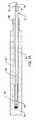
図1Aに示す本発明の一実施形態では、サファイア繊維を複合材に添加して熱電対の外側保護管24を製造する。サファイア構造繊維は、高強度・高温複合材に用いられるような非光学グレードのものであってもよい。サファイア繊維同士を複合材混合物中で重ねて外側保護管を強化してもよい。サファイア強化外側保護管24は、熱衝撃時の剪断、破壊及び割れに抵抗する。サファイアは赤くない種類のコランダムであり、硬さの尺度で非常に高い位置にある(9モース、人類に知られている2番目に硬い天然鉱物)。外側保護管複合材にサファイア繊維を追加すると、外側保護管24の寿命及び熱電対の運転期間が増大する。
Inone embodiment of the present inventionshown in FIG. 1A,to produce the outerside
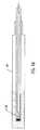
本発明の一実施形態では、サファイア強化外側保護管24は、図1Aに示す保護管の全長に沿って複合材中のファイア繊維を含んでいる。或いは、繊維の品質に応じて、外側保護管は、図1Bに示す複合材保護管の長さの一部のみにサファイア強化繊維を含んでいてもよい。図1Bにおいて、強化サファイア繊維は、外側保護管24の末端側12〜15インチに導入されるだけである。外側保護管24をなす複合材の強化に使用されるサファイアは非光学グレードの構造用繊維である。
Inone embodiment of the present invention, a sapphirestrengthening outerside
図1Aに示す本発明の実施形態では、サファイア強化外側保護管24は、熱電対内側保護管30の少なくとも一部分を囲繞する。かかる好ましい実施形態では、内側保護管30は高温高純度セラミック管からなる。例えば、かかるセラミック管はアルミナからなる。別の実施形態では、内側保護管30はサファイアからなる。熱電対10は、図に示すように、内側保護管30の内側に配置される。熱電対10は、素線12及び14の対から構成される。これらの素線は、熱電対が熱源に露出されたときにそれらの間に電位差が生じるように異なる金属含有量を有する。例示的な実施形態では、素線12及び14は共に白金とロジウムを含んでいるが、それらの主な相違点は、2本の素線で白金とロジウムの量が異なることである。好ましくは、素線の一方は約30%のロジウムを含有し、他方の素線は約6%のロジウムを含有する。両素線共に、残部は主に白金である。
In an embodiment of the present inventionshown in FIG. 1A, sapphirestrengthening outerside
素線は、温接点16と冷接点18で互いに接続されている。ガス化炉の温度測定に使用する場合、温接点16が熱源近傍に配置されるので、「温」及び「冷」という用語が用いられる。高温側端部の温度を示す2本の素線の電位差が測定される。電位差をどのように測定するかは重要でない。実際、電位差を測定するための様々な手段が当業者に公知である。これらの方法のいずれかを本発明で使用すればよい。例えば、熱電対回路に電圧計を設けてもよい。好ましい別法では、冷接点18温度送信器に設けてもよい。温度送信器で生成した信号を、信号伝送手段20によって制御室その他の場所へ中継すればよい。
Wire is connected toeach other physician
温接点と冷接点を除いて、それ以外の部分では、2本の素線12及び14は、互いに電気的に絶縁される。どのように絶縁するかは重要でないが、開示した実施形態では、電気的絶縁22は、高温高純度セラミック管によってもたらされる。かかるセラミック管は、例えば、アルミナからなる。
Exceptfor hotand coldjunctions, the otherpart, thetwo
前段落に記載したような熱電対10を単独で又はガス化炉の温度測定に常用されるサーモウェルとの組合せで使用する(つまり、外側保護管24が存在しない)場合、熱電対は、スラグその他炉内に存在する有害物質に素早く屈服する。そのため、本実施形態では、サファイア強化外側保護管24を、内側保護管30の少なくとも一部分の周囲、好ましくはスラグに露出される内側管部分全体を覆うように配設する。サファイア強化外側保護管24は、ガス化プロセスのスラグその他の物質に耐性である。サファイア強化材は、外側保護管を大幅に強化し、好適なことに熱衝撃及びエロージョンに耐性になる。ガス化プロセスで一般的な始動、停止その他の事象は、劇的な温度変化をもたらしかねない。かかる事象に付随する熱衝撃は、材料の能力を大きく超える応力を熱電対にもたらして、破損及び故障を招くことが多々ある。外側保護管24にサファイアを導入すると、保護管に著しい強度及びエロージョン耐性を与えて、その内部に収容された熱電対の有効寿命を増大させる。
Usingthe
一実施形態では、完成した熱電対及びサファイア強化外側保護管24は、遠位端つまり温接点16近傍の第1の端部26を有する。
Inoneembodiment,the finished thermocouples and sapphirestrengthening outerside
好ましい実施形態では、熱電対10は保護シースも備えており、例えば、図1A、図1B、図2及び図3に示すようなサファイアシース25を備える。サファイアシース25は、合成サファイア(純粋コランダム)からなる。サファイアシース25は、開口端部27と一体の閉塞部29とを含む。開口端部27と一体の閉塞部29の各々は、合成サファイアからなるものでよい。好ましい実施形態では、サファイアシース25は、長さ約10インチであるが、用途に応じてその他の長さにすることもできる。サファイアシース25は、ガス化炉内部の過酷な状況から熱電対10をさらに保護する。図4に示す別の実施形態では、サファイアシース25は使用しない。サファイアシース25内の熱電対10の配置は、図2に示すように、熱電対素線12及び14の遠位端に形成された「ピグテール」82によって促進することができる。ピグテール82は、熱電対10とサファイアシース25とを密着させる。ピグテール82を形成するには、熱電対素線12及び14を接合点80で一緒に捩り、余った素線を、サファイアシース25に熱電対を挿入したときにピグテール82がサファイアシース25の内壁に密着するように、構成する。ピグテール82(半径方向外側に偏向している)とサファイアシース25の内壁との間の抵抗によって密着性が生じ、熱電対とサファイアシースとの相対運動が妨げられる。別の実施形態では、熱電対10とサファイアシース25とを密着させるため、白金箔その他の材料で電気絶縁管22の周囲及び/又はサファイアシース25の内面の周囲を包んでもよい。
In a preferredembodiment, the
ある実施形態では、サファイア強化外側保護管24は既存の熱電対の全体又は大部分を覆うように延在していてもよい。
In someembodiments, the sapphirestrengthening outerside
好ましい実施形態では、外側保護管24は、成形プロセスを用いて、内側保護管30の周囲に形成される。内側保護管30を型(図示せず)内に、例えばスペーサーを用いて中心に配置する。次いで、サファイア強化セラミックを型に流し込んで、内側保護管30の少なくとも一部分の周囲で外側保護管24を一体に形成する。セラミックが硬化すると、外側保護管24は、内側保護管30の少なくとも一部分を囲繞する強固なサファイア強化部材となる。或いは、外側保護管24を別個に形成してから、内側保護管30を外側保護管24に挿入してもよい。
In a preferredembodiment, theouter-side
外部セラミック管24は幾分多孔質で、用途によってはスラグ及びガスの移動に鋭敏であることがある。スラグ及び/又はガスが外側保護管24を通して移動する場合、純粋サファイアシース25が、内側保護管30、熱電対素線12及び14への移動を防ぐ。好ましい実施形態では、サファイアシース25は長さ約10インチしか延在しない。当業者には自明であろうが、スラグ及び/又はガスが炉の壁の近くで移動すると、温度が低下する。かかる冷却の結果、遠位端26から10インチ以上の距離で外側保護管24を通して移動するスラグ及び/又はガスは通例ほとんど或いは全く存在しない。典型的には、スラグは、遠位端26から5インチ以内で凝固する。しかし、応用としてのインアズマッチ(inasmuch)は、外側保護管24の遠位端26から10インチ以上の距離でスラグ及び/又はガスの移動が起こるようとでは、必要に応じて、サファイアシース25の長さを長くしてもよい。
External
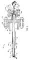
次に図3〜図4を参照すると、外側保護管24は、支持管1と外側保護管24の第1の端部28で嵌合していてもよい。図3に示す好ましい実施形態では、外側保護管24は、支持管1の遠位端内側に密着する第2の端部28で先細になっている(テーパが付けられている)。高温セメントを用いて支持管1と外側保護管24の第2の端部との間の環状部をシールしてもよい。或いは、外側保護管24は、特に限定されないが、遠位端が先細の支持管と(支持管とぴったり嵌合するように)開口端部が広がった外側保護管との嵌合を始めとする、任意の別の簡便な手段で支持管1に取り付けてもよい。支持管1は、ステンレス鋼その他のエロージョン耐性材料を含んでいてもよいし、圧力容器ガス化炉の外側鋼壁40を貫通する着脱自在なフランジ74から延在する。図3〜図4に示す実施形態では、支持管1は、外側保護管24の先細の第2の端部28と嵌合する近位端よりも遠位端の径が大きい入れ子式管である。或いは、支持管1は入れ子式でなくてもよい。
Referring ThentoFIGS. 3-4in the following, theouter-side
サファイア強化外側保護管24は少なくとも温接点16を囲繞する。こうすれば、精密な温度測定には、オペレーターは外側保護管(したがって熱電対温接点)をガス化流に挿入すればよい。
Sapphirestrengthening outerside
一実施形態では、サファイア強化外側保護管24は、内側保護管30の少なくとも一部分の周囲で成形される。サファイアシース25を含めた熱電対10は、内側保護管30内に摺動自在であり、閉塞部29が図1で示すように内側保護管の遠位端に当接するまで入り込む。閉塞部29と内側保護管30との接触によって正確な炉温度測定が図られる。
Inoneembodiment, the sapphirestrengthening outerside
ある実施形態では、サファイア強化外側保護管の厚さは、約1インチである。他の実施形態は、サファイア強化外側保護管24の厚さ及び長さは種々変更できる。
In certainembodiments, the thickness of the sapphirestrengthening outerside protectivetube is about 1 inch. Otherembodiments,thickness and length of the sapphirestrengthening outerside
図3〜図4に示す実施形態では、熱電対10はガス化炉40に、遠位端26から挿入される。熱電対10は、フランジ付レジューサー76を通して、外部管24と支持管1の組合せに挿入される。支持管1はボールスイベル及び支持体84で支持され、支持体84はフランジ付レジューサー76と接触して嵌合する。熱電対10の遠位端16は、外側保護管24の遠位端26の近傍に配置される。好ましくは外側保護管24の内面と熱電対の遠位端16との間には約0.125〜約0.25インチの間隔が維持される。熱電対10の遠位端16は、好ましくは、前述のサファイアシース25を備えていてもよい。熱電対10は、外側保護管24で囲繞されていれば、サーモウェルを必要とせずにガス化流に直接挿入することができる。
In the embodimentshown inFIGS. 3-4, the
熱電対10の素線12及び14の近位端は、電気絶縁体22の近位端、及び/又はサファイア強化外側保護管24及び支持管1(図3に示すように、支持管が電気絶縁体22と境界が一致する場合)を通過して延在する。素線は圧力シール取付け具70を貫通する。圧力シール取付け具70は、着脱自在なフランジ74に嵌合するブッシング72に隣接して配置される。着脱自在なフランジ74は、圧力容器ガス化炉の外側鋼壁40と嵌合するフランジ付レジューサー76と嵌合する。
Proximal end of the
2つの別個の接続具(74及び76)の使用は、外側管24と支持管1の組合せを取外さずに、熱電対10を交換することができるので、効率的である。或いは、フランジ74及び76に代えて、ネジ付きキャップ及びノズルその他の接続手段を用いてもよい。
The use of two separateconnectors (74 and 76),without removing the combination of the
外側保護管アセンブリ24を備える熱電対10は、ガス化反応でのスラグ耐性が増大する。開示された実施形態では、スラグは外側保護管24の周囲を直接通過し、移動するスラグからの外側保護管を遮蔽するサーモウェルは存在しない。サファイア強化外側保護管24には最終的には破損が生じるおそれがある。しかし、サファイア強化外側保護管によって熱電対の耐用年数が延びる。サファイア強化外側保護管24が最終的に破損すると、サファイアシース25及び/又は内側保護管30は、エロージョン及び腐食の作用を受ける。内側保護管30及びサファイアシース25が破損すると、素線12及び14と温接点16が保護されずに残り、熱電対10も破損する。サファイア強化外側保護管24の適切な長さの選択は、温度及びガス組成を始めとするプロセスの特徴について熟知し、本願の教示内容に接した当業者が容易になし得る事項である。
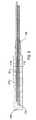
図5〜図6に示す実施形態のような別の実施形態では、2本以上の保護管、例えば、内側保護管130及び131を型内に一緒に配置してから、内側保護管の周囲でサファイア強化外側保護管124を形成する。好ましい実施形態では、2本以上の内側保護管の各遠位端は、外側保護管124に沿って異なる長さで互い違いに配置する。2本以上の内側保護管は、2以上の熱電対の導入を容易にする。このように複数の内側保護管を互い違いに並べた配置は、熱電対の交換を要するまでの供用時間が増大する。例えば、2本の内側保護管130及び131を示す図5の実施形態では、外側保護管124の破損又はそれを通してのスラグ及び/又はガス移動は、内側保護管130に挿入された熱電対の最終的破損を招くことがある。しかし、内側保護管131に収容された熱電対の破損はある程度遅くなる。外側保護管124が内側保護管130及び131の周囲に設けられるので、外側保護管124の破損は、内側保護管131への直接的径路を有さないことがある。結局は外側保護管124がさらに破損して、内側保護管131に達するかもしれないが、炉内の温度は炉壁に近づくほど低下するので、内側保護管130及び131が破損するまでの時間は通常さらにずれる。本明細書の教示内容に接した当業者には自明であろうが、外側保護管124の破損は、まず、反応チャンバーの最も高温の部分である遠位端126で起こる可能性が高く、それ以上の破損は通常は外側保護管の近位端128に向かって遅れて起こる。外側保護管124に沿って互い違いにずらした長さで各々熱電対を収容する2本以上の内側保護管を用いると、最も遠位端側に位置する熱電対の破壊後も、炉の運転を中断せずに継続することができる。本明細書の教示内容に接した当業者には自明であろうが、2本以上の内側保護管を使用してもよいが、図5〜図6に示す実施形態は、サファイア強化外側保護管124で可能な複数の熱電対の例示にすぎない。第2の(又はさらに追加の)熱電対で得られる精度は、炉の最も高温部分に関しては第1の熱電対ほど高くないかもしれないが、第1の熱電対の破損までに収集されたデータに基づいて、第2の(又はさらに追加の)熱電対のための読取り値を較正及び補正することができるので、その差はプロセス制御者に問題を提起しない。
5In anotherembodiment, such as theembodiment shown into 6,two or more protectivetubes, forexample, place together innerside
本発明が、発明の特別の例示的な実施形態に関して特に示され記述されている一方、形式と詳細の様々な変更が、発明の精神及び範囲から外れずに行なわれるかもしれないことは当業者によって理解されるだろう。上記の記述された実施形態は例示にすぎず、本発明の範囲の限定と見なされてはならない。
【図面の簡単な説明】
【図1A】
本発明の一実施形態に係る熱電対及び外側保護管の断面図。
【図1B】
本発明の別の実施形態に係る熱電対及び外側保護管の断面図。
【図2】
図1の熱電対及びシースの断面図。
【図3】
本発明の一実施形態に係るガス化炉壁及び熱電対の一部分の断面図。
【図4】
本発明の別の実施形態に係るガス化炉壁及び熱電対の一部分の断面図。
【図5】
本発明の別の実施形態に係る外側保護管の長手方向断面図。
【図6】
図5の保護管の水平断面図。The present invention, while has been particularly shown and described with respect to particularexemplaryembodiments of the invention, form and various changes in detail,it may be carried out without departing from the spirit and scope of the invention those skilled in the art Will be understood by. The above describedembodiments aremerely exemplary and should not be considered as limiting the scope of the invention.
[Brief description of the drawings]
FIG. 1A
Sectional view of the thermocouple and the outerside protectivetubeaccording to an embodiment of the present invention.
FIG. 1B
Sectional view of the thermocouple and the outerside protectivetubeaccording to another embodiment of the present invention.
[Figure 2]
Thermocouple and across-sectional view of thesheathof Figure 1.
[Fig. 3]
The sectionalview of a part of gasificationfurnace wall and thermocoupleconcerning one embodiment of the present invention.
[Fig. 4]
Sectionaldrawing of the gasificationfurnace wallwhich concerns on another embodiment of this invention, and a part of thermocouple.
[Figure 5]
Longitudinal cross-sectionalview of the outerside protectivetubeaccording to another embodiment of the present invention.
[Fig. 6]
FIG. 6 is ahorizontal sectionalview of the protectivetube in FIG. 5.
Claims (23)
Translated fromJapaneseAn apparatus comprising a thermocouple for temperature measurement in a gasification process, wherein an outer protective tube made of a sapphire reinforced composite material reinforced with a structural grade non-optical sapphire fiber is disposed around the thermocouple. The apparatusfurther comprising a sapphire sheath that surrounds at least a portion andis removably disposed about a distal end of the thermocouple .
The apparatus of claim 1, further comprising an inner protective tube inside the outer protective tube, the inner protective tube being capable of accommodating the thermocouple.
The apparatus of claim 2, wherein the inner protective tube is made of alumina.
The apparatus of claim 2, wherein the inner protective tube is made of sapphire.
The apparatus according to claim 1, wherein the outer protective tube is attached to a support tube.
The apparatus of claim 5, wherein the outer protective tube is tapered to fit within the distal end of the support tube.
The apparatus according to claim 5 or 6, wherein the outer protective tube and the support tube completely surround the thermocouple.
The apparatus according to any one of claims 1 to 7, wherein the outer protective tube is inserted directly into the gasification stream without a thermowell.
The apparatus according to claim 1, wherein the outer protective tube is formed around the inner protective tube.
The device according toany one of claims 1 to 9, wherein the sapphire sheath is made of synthetic sapphire.
11. A device according toany one of the preceding claims , wherein the sapphire sheath has an open end and a closure.
The apparatus of claim11 , wherein the open end and the closure are made of synthetic sapphire.
To facilitate adhesion between the sapphire sheath and the thermocouple, the distal end of the pair of wires of the thermocouple is bent in a form deflected radially outward, one of claims1 to12 The apparatus of claim 1.
It said thermocouple in order to adhere the sapphire sheath the thermocouple is wrapped in platinum foil, apparatus according to any one of claims1 to13.
一端が温接点で接続し、他端が冷接点で接続し、その他の部分は絶縁管で電気的に絶縁された異種金属の素線の対からなる熱電対と、
前記素線の対と前記絶縁管とを収容できる熱電対内側保護管と、
構造グレードの非光学用サファイア繊維で強化したサファイア強化複合材からなる熱電対外側保護管と、
前記熱電対の遠位端を収容できるサファイアシースと
を備える熱電対システム。
A thermocouple system for use in a gasification system,
One end is connected with a hot junction, the other end is connected with a cold junction, and the other part is a thermocouple composed of a pair of different metal wires electrically insulated by an insulating tube,
A thermocouple inner protective tube capable of accommodating the pair of strands and the insulating tube;
A thermocouple outer protective tube made of a sapphire reinforced composite reinforced with structural grade non-optical sapphire fibers;
A thermocouple system comprising: a sapphire sheath capable of accommodating a distal end of the thermocouple.
The thermocouple system of claim15 , wherein the outer protective tube is integrally formed around the inner protective tube.
The thermocouple system according to claim15 or16 , wherein the inner protective tube is made of alumina.
The thermocouple system according to claim15 or16 , wherein the inner protective tube is made of sapphire.
The insulating tube is made of alumina, thermocouple system according to any one of claims15 to18.
The thermocouple system according to any one of claims15 to19 , further comprising a support pipe connected to the outer protective pipe and extending into the gasification furnace.
21. A thermocouple system according to any one of claims15 to20 for measuring temperatures in the range of 1300 <0> F to 3000 <0> F (700 <0> C to 1650 <0> C).
The thermocouple system according to any one of claims15 to21 , wherein the pair of strands is made of platinum, rhodium, or a mixture thereof.
一端が温接点で接続し、他端が冷接点で接続し、その他の部分は絶縁管で電気的に絶縁された異種金属の素線の対からなる熱電対を準備する段階と、
構造グレードの非光学用サファイア繊維で強化したサファイア強化複合材からなる外側保護管を準備して、支持管と接続する段階と、
サファイアシースを準備して前記熱電対の温接点側の端部を収容する段階と、
前記外側保護管及び支持管をガス化炉に挿入する段階と、
前記熱電対を前記外側保護管に挿入する段階と
を含む方法。
A method for measuring temperature in a gasification process comprising:
Preparing a thermocouple composed of a pair of dissimilar metal strands, one end connected by a hot junction, the other end connected by a cold junction, and the other part electrically insulated by an insulating tube;
Providing an outer protective tube of sapphire reinforced composite reinforced with structural grade non-optical sapphire fibers and connecting to a support tube;
Preparing a sapphire sheath to accommodate the end of the thermocouple on the hot junction side;
Inserting the outer protective tube and the support tube into a gasification furnace;
Inserting the thermocouple into the outer protective tube.
Applications Claiming Priority (3)
| Application Number | Priority Date | Filing Date | Title |
|---|---|---|---|
| US15934699P | 1999-10-13 | 1999-10-13 | |
| US60/159,346 | 1999-10-13 | ||
| PCT/US2000/026181WO2001027579A1 (en) | 1999-10-13 | 2000-09-22 | Sapphire reinforced thermocouple protection tube |
Publications (3)
| Publication Number | Publication Date |
|---|---|
| JP2003511689A JP2003511689A (en) | 2003-03-25 |
| JP2003511689A5 JP2003511689A5 (en) | 2011-02-17 |
| JP5331282B2true JP5331282B2 (en) | 2013-10-30 |
Family
ID=22572189
Family Applications (1)
| Application Number | Title | Priority Date | Filing Date |
|---|---|---|---|
| JP2001530543AExpired - LifetimeJP5331282B2 (en) | 1999-10-13 | 2000-09-22 | Sapphire reinforced thermocouple protection tube |
Country Status (11)
| Country | Link |
|---|---|
| US (1) | US6536950B1 (en) |
| JP (1) | JP5331282B2 (en) |
| KR (1) | KR100649519B1 (en) |
| CN (1) | CN1192222C (en) |
| AR (1) | AR026008A1 (en) |
| AU (1) | AU782587B2 (en) |
| CA (1) | CA2387412C (en) |
| MX (1) | MXPA02003794A (en) |
| TW (1) | TW472138B (en) |
| WO (1) | WO2001027579A1 (en) |
| ZA (1) | ZA200203030B (en) |
Families Citing this family (398)
| Publication number | Priority date | Publication date | Assignee | Title |
|---|---|---|---|---|
| JP5331282B2 (en)* | 1999-10-13 | 2013-10-30 | ジーイー・エナジー・ユーエスエー・エルエルシー | Sapphire reinforced thermocouple protection tube |
| CN2494505Y (en)* | 2001-07-15 | 2002-06-05 | 昆山德士古气化服务有限公司 | Thermocouple protection casing |
| EP1298423A1 (en)* | 2001-10-01 | 2003-04-02 | Vesuvius Crucible Company | Pyrometer |
| US7004623B2 (en)* | 2002-03-21 | 2006-02-28 | Jon Nakagawa | Disposable sheath for data logger probe and method for measuring and recording temperature in a closed container |
| US6857776B2 (en)* | 2002-12-12 | 2005-02-22 | Ametek, Inc. | Connectorized high-temperature thermocouple |
| US7153024B2 (en)* | 2004-01-28 | 2006-12-26 | Denso Corporation | Sensor and temperature sensor capable of automatic installation |
| US7465086B1 (en)* | 2005-03-05 | 2008-12-16 | Foreman Instrumentation & Controls, Inc. | Adjustable length thermowell |
| CZ302212B6 (en)* | 2006-03-29 | 2010-12-22 | CRYTUR@@spol@@s@r@@o | Thermocouple probe with a casing for measuring temperature values in extreme conditions |
| US7997795B2 (en)* | 2006-05-02 | 2011-08-16 | Watlow Electric Manufacturing Company | Temperature sensors and methods of manufacture thereof |
| US8771604B2 (en)* | 2007-02-06 | 2014-07-08 | Aerojet Rocketdyne Of De, Inc. | Gasifier liner |
| KR100893102B1 (en)* | 2007-07-24 | 2009-04-14 | 주식회사 우진 | Stainless steel mandrel winding type temperature sensing resistance element, resistance thermometer and manufacturing method thereof |
| DE102008029192A1 (en)* | 2008-03-13 | 2009-09-24 | Epcos Ag | Sensor for detecting a physical quantity and method for manufacturing the sensor |
| JP5155246B2 (en)* | 2008-05-09 | 2013-03-06 | 日本特殊陶業株式会社 | Temperature sensor |
| JP5198934B2 (en)* | 2008-05-09 | 2013-05-15 | 日本特殊陶業株式会社 | Temperature sensor |
| US10378106B2 (en) | 2008-11-14 | 2019-08-13 | Asm Ip Holding B.V. | Method of forming insulation film by modified PEALD |
| US9394608B2 (en) | 2009-04-06 | 2016-07-19 | Asm America, Inc. | Semiconductor processing reactor and components thereof |
| US9297705B2 (en)* | 2009-05-06 | 2016-03-29 | Asm America, Inc. | Smart temperature measuring device |
| US8382370B2 (en) | 2009-05-06 | 2013-02-26 | Asm America, Inc. | Thermocouple assembly with guarded thermocouple junction |
| US8297129B2 (en)* | 2009-06-18 | 2012-10-30 | Muskopf Brian A | Instrument mounting system and method |
| WO2011004506A1 (en)* | 2009-07-10 | 2011-01-13 | 本田技研工業株式会社 | Nail puncture test equipment having temperature measurement function |
| US8802201B2 (en) | 2009-08-14 | 2014-08-12 | Asm America, Inc. | Systems and methods for thin-film deposition of metal oxides using excited nitrogen-oxygen species |
| EP2386843B1 (en)* | 2010-05-11 | 2016-08-03 | Innovatherm Prof. Dr. Leisenberg GmbH & Co. KG | Thermocouple |
| US8485010B1 (en) | 2010-12-06 | 2013-07-16 | Zeeco, Inc. | Method and apparatus for installing a retractable thermocouple |
| KR101262698B1 (en)* | 2010-12-13 | 2013-05-15 | 두산중공업 주식회사 | Device for measuring plane temperature distribution of an electrode for the fuel cell |
| US9312155B2 (en) | 2011-06-06 | 2016-04-12 | Asm Japan K.K. | High-throughput semiconductor-processing apparatus equipped with multiple dual-chamber modules |
| US10364496B2 (en) | 2011-06-27 | 2019-07-30 | Asm Ip Holding B.V. | Dual section module having shared and unshared mass flow controllers |
| US10854498B2 (en) | 2011-07-15 | 2020-12-01 | Asm Ip Holding B.V. | Wafer-supporting device and method for producing same |
| US20130023129A1 (en) | 2011-07-20 | 2013-01-24 | Asm America, Inc. | Pressure transmitter for a semiconductor processing environment |
| US9017481B1 (en) | 2011-10-28 | 2015-04-28 | Asm America, Inc. | Process feed management for semiconductor substrate processing |
| DE102012105547A1 (en)* | 2012-06-26 | 2014-01-16 | Endress + Hauser Wetzer Gmbh + Co. Kg | Temperature measuring device, measuring element for a temperature measuring device and method for producing the temperature measuring device |
| US9659799B2 (en) | 2012-08-28 | 2017-05-23 | Asm Ip Holding B.V. | Systems and methods for dynamic semiconductor process scheduling |
| US9429481B2 (en) | 2012-08-31 | 2016-08-30 | Ametek, Inc. | Apparatus and method for measuring total air temperature within an airflow |
| US10714315B2 (en) | 2012-10-12 | 2020-07-14 | Asm Ip Holdings B.V. | Semiconductor reaction chamber showerhead |
| PL2926100T3 (en)* | 2012-11-30 | 2021-01-11 | Lummus Technology Llc | Thermal sensing system |
| US20160376700A1 (en) | 2013-02-01 | 2016-12-29 | Asm Ip Holding B.V. | System for treatment of deposition reactor |
| US9589770B2 (en) | 2013-03-08 | 2017-03-07 | Asm Ip Holding B.V. | Method and systems for in-situ formation of intermediate reactive species |
| US9484191B2 (en) | 2013-03-08 | 2016-11-01 | Asm Ip Holding B.V. | Pulsed remote plasma method and system |
| WO2015021096A1 (en)* | 2013-08-07 | 2015-02-12 | Ametek, Inc. | High temperature probe |
| US9240412B2 (en) | 2013-09-27 | 2016-01-19 | Asm Ip Holding B.V. | Semiconductor structure and device and methods of forming same using selective epitaxial process |
| CN103808421B (en)* | 2014-01-22 | 2016-05-11 | 东风商用车有限公司 | Armored thermocouple assembly for measuring temperature of cylinder cover and manufacturing and mounting method thereof |
| US10683571B2 (en) | 2014-02-25 | 2020-06-16 | Asm Ip Holding B.V. | Gas supply manifold and method of supplying gases to chamber using same |
| US9593847B1 (en) | 2014-03-05 | 2017-03-14 | Zeeco, Inc. | Fuel-flexible burner apparatus and method for fired heaters |
| EA037107B1 (en)* | 2014-03-11 | 2021-02-08 | Эметек, Инк. | High temperature probe |
| US10167557B2 (en) | 2014-03-18 | 2019-01-01 | Asm Ip Holding B.V. | Gas distribution system, reactor including the system, and methods of using the same |
| US11015245B2 (en) | 2014-03-19 | 2021-05-25 | Asm Ip Holding B.V. | Gas-phase reactor and system having exhaust plenum and components thereof |
| US9593848B2 (en) | 2014-06-09 | 2017-03-14 | Zeeco, Inc. | Non-symmetrical low NOx burner apparatus and method |
| CN105300424A (en)* | 2014-07-28 | 2016-02-03 | 德国威卡Aw股份两合公司 | Adapter for measuring a physical variable |
| US10858737B2 (en) | 2014-07-28 | 2020-12-08 | Asm Ip Holding B.V. | Showerhead assembly and components thereof |
| US9890456B2 (en) | 2014-08-21 | 2018-02-13 | Asm Ip Holding B.V. | Method and system for in situ formation of gas-phase compounds |
| AT516331B1 (en)* | 2014-10-03 | 2016-10-15 | 4Tex Gmbh | Holder for sensors |
| US9657845B2 (en) | 2014-10-07 | 2017-05-23 | Asm Ip Holding B.V. | Variable conductance gas distribution apparatus and method |
| US10941490B2 (en) | 2014-10-07 | 2021-03-09 | Asm Ip Holding B.V. | Multiple temperature range susceptor, assembly, reactor and system including the susceptor, and methods of using the same |
| US9885610B2 (en) | 2014-12-22 | 2018-02-06 | Rosemount Inc. | Thermowell system with vibration detection |
| KR102263121B1 (en) | 2014-12-22 | 2021-06-09 | 에이에스엠 아이피 홀딩 비.브이. | Semiconductor device and manufacuring method thereof |
| US10529542B2 (en) | 2015-03-11 | 2020-01-07 | Asm Ip Holdings B.V. | Cross-flow reactor and method |
| US10276355B2 (en) | 2015-03-12 | 2019-04-30 | Asm Ip Holding B.V. | Multi-zone reactor, system including the reactor, and method of using the same |
| CN104989382A (en)* | 2015-06-26 | 2015-10-21 | 中国石油化工股份有限公司胜利油田分公司 | Heavy oil thermal recovery wellhead high-temperature-resistant pressure transmitter |
| US10458018B2 (en) | 2015-06-26 | 2019-10-29 | Asm Ip Holding B.V. | Structures including metal carbide material, devices including the structures, and methods of forming same |
| US9891111B2 (en)* | 2015-06-30 | 2018-02-13 | Rosemount Inc. | Thermowell with infrared sensor |
| US10600673B2 (en) | 2015-07-07 | 2020-03-24 | Asm Ip Holding B.V. | Magnetic susceptor to baseplate seal |
| US9960072B2 (en) | 2015-09-29 | 2018-05-01 | Asm Ip Holding B.V. | Variable adjustment for precise matching of multiple chamber cavity housings |
| US10211308B2 (en) | 2015-10-21 | 2019-02-19 | Asm Ip Holding B.V. | NbMC layers |
| US10322384B2 (en) | 2015-11-09 | 2019-06-18 | Asm Ip Holding B.V. | Counter flow mixer for process chamber |
| US11139308B2 (en) | 2015-12-29 | 2021-10-05 | Asm Ip Holding B.V. | Atomic layer deposition of III-V compounds to form V-NAND devices |
| US10468251B2 (en) | 2016-02-19 | 2019-11-05 | Asm Ip Holding B.V. | Method for forming spacers using silicon nitride film for spacer-defined multiple patterning |
| US10529554B2 (en) | 2016-02-19 | 2020-01-07 | Asm Ip Holding B.V. | Method for forming silicon nitride film selectively on sidewalls or flat surfaces of trenches |
| US10501866B2 (en) | 2016-03-09 | 2019-12-10 | Asm Ip Holding B.V. | Gas distribution apparatus for improved film uniformity in an epitaxial system |
| US10343920B2 (en) | 2016-03-18 | 2019-07-09 | Asm Ip Holding B.V. | Aligned carbon nanotubes |
| US9892913B2 (en) | 2016-03-24 | 2018-02-13 | Asm Ip Holding B.V. | Radial and thickness control via biased multi-port injection settings |
| US10190213B2 (en) | 2016-04-21 | 2019-01-29 | Asm Ip Holding B.V. | Deposition of metal borides |
| US10865475B2 (en) | 2016-04-21 | 2020-12-15 | Asm Ip Holding B.V. | Deposition of metal borides and silicides |
| US10032628B2 (en) | 2016-05-02 | 2018-07-24 | Asm Ip Holding B.V. | Source/drain performance through conformal solid state doping |
| US10367080B2 (en) | 2016-05-02 | 2019-07-30 | Asm Ip Holding B.V. | Method of forming a germanium oxynitride film |
| US10295491B2 (en)* | 2016-05-11 | 2019-05-21 | Daily Instruments | Mineral insulated sheathed assembly with insulation resistance indicator |
| US10288490B2 (en) | 2016-05-11 | 2019-05-14 | Daily Thermetrics Corp. | Mineral insulated sheathed assembly with grounded and ungrounded temperature sensors |
| KR102592471B1 (en) | 2016-05-17 | 2023-10-20 | 에이에스엠 아이피 홀딩 비.브이. | Method of forming metal interconnection and method of fabricating semiconductor device using the same |
| US11453943B2 (en) | 2016-05-25 | 2022-09-27 | Asm Ip Holding B.V. | Method for forming carbon-containing silicon/metal oxide or nitride film by ALD using silicon precursor and hydrocarbon precursor |
| US10388509B2 (en) | 2016-06-28 | 2019-08-20 | Asm Ip Holding B.V. | Formation of epitaxial layers via dislocation filtering |
| US10612137B2 (en) | 2016-07-08 | 2020-04-07 | Asm Ip Holdings B.V. | Organic reactants for atomic layer deposition |
| US9859151B1 (en) | 2016-07-08 | 2018-01-02 | Asm Ip Holding B.V. | Selective film deposition method to form air gaps |
| US10714385B2 (en) | 2016-07-19 | 2020-07-14 | Asm Ip Holding B.V. | Selective deposition of tungsten |
| KR102354490B1 (en) | 2016-07-27 | 2022-01-21 | 에이에스엠 아이피 홀딩 비.브이. | Method of processing a substrate |
| KR102532607B1 (en) | 2016-07-28 | 2023-05-15 | 에이에스엠 아이피 홀딩 비.브이. | Substrate processing apparatus and method of operating the same |
| US9887082B1 (en) | 2016-07-28 | 2018-02-06 | Asm Ip Holding B.V. | Method and apparatus for filling a gap |
| US9812320B1 (en) | 2016-07-28 | 2017-11-07 | Asm Ip Holding B.V. | Method and apparatus for filling a gap |
| US10395919B2 (en) | 2016-07-28 | 2019-08-27 | Asm Ip Holding B.V. | Method and apparatus for filling a gap |
| KR102613349B1 (en) | 2016-08-25 | 2023-12-14 | 에이에스엠 아이피 홀딩 비.브이. | Exhaust apparatus and substrate processing apparatus and thin film fabricating method using the same |
| US10410943B2 (en) | 2016-10-13 | 2019-09-10 | Asm Ip Holding B.V. | Method for passivating a surface of a semiconductor and related systems |
| US10643826B2 (en) | 2016-10-26 | 2020-05-05 | Asm Ip Holdings B.V. | Methods for thermally calibrating reaction chambers |
| US11532757B2 (en) | 2016-10-27 | 2022-12-20 | Asm Ip Holding B.V. | Deposition of charge trapping layers |
| US10643904B2 (en) | 2016-11-01 | 2020-05-05 | Asm Ip Holdings B.V. | Methods for forming a semiconductor device and related semiconductor device structures |
| US10714350B2 (en) | 2016-11-01 | 2020-07-14 | ASM IP Holdings, B.V. | Methods for forming a transition metal niobium nitride film on a substrate by atomic layer deposition and related semiconductor device structures |
| US10435790B2 (en) | 2016-11-01 | 2019-10-08 | Asm Ip Holding B.V. | Method of subatmospheric plasma-enhanced ALD using capacitively coupled electrodes with narrow gap |
| US10229833B2 (en) | 2016-11-01 | 2019-03-12 | Asm Ip Holding B.V. | Methods for forming a transition metal nitride film on a substrate by atomic layer deposition and related semiconductor device structures |
| US10134757B2 (en) | 2016-11-07 | 2018-11-20 | Asm Ip Holding B.V. | Method of processing a substrate and a device manufactured by using the method |
| KR102546317B1 (en) | 2016-11-15 | 2023-06-21 | 에이에스엠 아이피 홀딩 비.브이. | Gas supply unit and substrate processing apparatus including the same |
| US10340135B2 (en) | 2016-11-28 | 2019-07-02 | Asm Ip Holding B.V. | Method of topologically restricted plasma-enhanced cyclic deposition of silicon or metal nitride |
| KR102762543B1 (en) | 2016-12-14 | 2025-02-05 | 에이에스엠 아이피 홀딩 비.브이. | Substrate processing apparatus |
| US11447861B2 (en) | 2016-12-15 | 2022-09-20 | Asm Ip Holding B.V. | Sequential infiltration synthesis apparatus and a method of forming a patterned structure |
| US11581186B2 (en) | 2016-12-15 | 2023-02-14 | Asm Ip Holding B.V. | Sequential infiltration synthesis apparatus |
| KR102700194B1 (en) | 2016-12-19 | 2024-08-28 | 에이에스엠 아이피 홀딩 비.브이. | Substrate processing apparatus |
| RU170706U1 (en)* | 2016-12-22 | 2017-05-03 | Общество С Ограниченной Ответственностью Научно-Производственное Предприятие "Элемер" (Ооо Нпп "Элемер") | HIGH TEMPERATURE RESISTANCE THERMOMETER |
| US10269558B2 (en) | 2016-12-22 | 2019-04-23 | Asm Ip Holding B.V. | Method of forming a structure on a substrate |
| US10867788B2 (en) | 2016-12-28 | 2020-12-15 | Asm Ip Holding B.V. | Method of forming a structure on a substrate |
| US11390950B2 (en) | 2017-01-10 | 2022-07-19 | Asm Ip Holding B.V. | Reactor system and method to reduce residue buildup during a film deposition process |
| US10655221B2 (en) | 2017-02-09 | 2020-05-19 | Asm Ip Holding B.V. | Method for depositing oxide film by thermal ALD and PEALD |
| US10468261B2 (en) | 2017-02-15 | 2019-11-05 | Asm Ip Holding B.V. | Methods for forming a metallic film on a substrate by cyclical deposition and related semiconductor device structures |
| US10283353B2 (en) | 2017-03-29 | 2019-05-07 | Asm Ip Holding B.V. | Method of reforming insulating film deposited on substrate with recess pattern |
| US10529563B2 (en) | 2017-03-29 | 2020-01-07 | Asm Ip Holdings B.V. | Method for forming doped metal oxide films on a substrate by cyclical deposition and related semiconductor device structures |
| KR102457289B1 (en) | 2017-04-25 | 2022-10-21 | 에이에스엠 아이피 홀딩 비.브이. | Method for depositing a thin film and manufacturing a semiconductor device |
| US10446393B2 (en) | 2017-05-08 | 2019-10-15 | Asm Ip Holding B.V. | Methods for forming silicon-containing epitaxial layers and related semiconductor device structures |
| US10770286B2 (en) | 2017-05-08 | 2020-09-08 | Asm Ip Holdings B.V. | Methods for selectively forming a silicon nitride film on a substrate and related semiconductor device structures |
| US10892156B2 (en) | 2017-05-08 | 2021-01-12 | Asm Ip Holding B.V. | Methods for forming a silicon nitride film on a substrate and related semiconductor device structures |
| US11293841B2 (en)* | 2017-05-21 | 2022-04-05 | Jms Southeast, Inc. | Process inserts, assemblies, and related methods for high velocity applications |
| US10504742B2 (en) | 2017-05-31 | 2019-12-10 | Asm Ip Holding B.V. | Method of atomic layer etching using hydrogen plasma |
| US10886123B2 (en) | 2017-06-02 | 2021-01-05 | Asm Ip Holding B.V. | Methods for forming low temperature semiconductor layers and related semiconductor device structures |
| US12040200B2 (en) | 2017-06-20 | 2024-07-16 | Asm Ip Holding B.V. | Semiconductor processing apparatus and methods for calibrating a semiconductor processing apparatus |
| US11306395B2 (en) | 2017-06-28 | 2022-04-19 | Asm Ip Holding B.V. | Methods for depositing a transition metal nitride film on a substrate by atomic layer deposition and related deposition apparatus |
| US10685834B2 (en) | 2017-07-05 | 2020-06-16 | Asm Ip Holdings B.V. | Methods for forming a silicon germanium tin layer and related semiconductor device structures |
| KR20190009245A (en) | 2017-07-18 | 2019-01-28 | 에이에스엠 아이피 홀딩 비.브이. | Methods for forming a semiconductor device structure and related semiconductor device structures |
| US10541333B2 (en) | 2017-07-19 | 2020-01-21 | Asm Ip Holding B.V. | Method for depositing a group IV semiconductor and related semiconductor device structures |
| US11374112B2 (en) | 2017-07-19 | 2022-06-28 | Asm Ip Holding B.V. | Method for depositing a group IV semiconductor and related semiconductor device structures |
| US11018002B2 (en) | 2017-07-19 | 2021-05-25 | Asm Ip Holding B.V. | Method for selectively depositing a Group IV semiconductor and related semiconductor device structures |
| US10590535B2 (en) | 2017-07-26 | 2020-03-17 | Asm Ip Holdings B.V. | Chemical treatment, deposition and/or infiltration apparatus and method for using the same |
| US10312055B2 (en) | 2017-07-26 | 2019-06-04 | Asm Ip Holding B.V. | Method of depositing film by PEALD using negative bias |
| US10605530B2 (en) | 2017-07-26 | 2020-03-31 | Asm Ip Holding B.V. | Assembly of a liner and a flange for a vertical furnace as well as the liner and the vertical furnace |
| TWI815813B (en) | 2017-08-04 | 2023-09-21 | 荷蘭商Asm智慧財產控股公司 | Showerhead assembly for distributing a gas within a reaction chamber |
| US10770336B2 (en) | 2017-08-08 | 2020-09-08 | Asm Ip Holding B.V. | Substrate lift mechanism and reactor including same |
| US10692741B2 (en) | 2017-08-08 | 2020-06-23 | Asm Ip Holdings B.V. | Radiation shield |
| US11769682B2 (en) | 2017-08-09 | 2023-09-26 | Asm Ip Holding B.V. | Storage apparatus for storing cassettes for substrates and processing apparatus equipped therewith |
| US10249524B2 (en) | 2017-08-09 | 2019-04-02 | Asm Ip Holding B.V. | Cassette holder assembly for a substrate cassette and holding member for use in such assembly |
| US11139191B2 (en) | 2017-08-09 | 2021-10-05 | Asm Ip Holding B.V. | Storage apparatus for storing cassettes for substrates and processing apparatus equipped therewith |
| USD900036S1 (en) | 2017-08-24 | 2020-10-27 | Asm Ip Holding B.V. | Heater electrical connector and adapter |
| US11830730B2 (en) | 2017-08-29 | 2023-11-28 | Asm Ip Holding B.V. | Layer forming method and apparatus |
| US11056344B2 (en) | 2017-08-30 | 2021-07-06 | Asm Ip Holding B.V. | Layer forming method |
| US11295980B2 (en) | 2017-08-30 | 2022-04-05 | Asm Ip Holding B.V. | Methods for depositing a molybdenum metal film over a dielectric surface of a substrate by a cyclical deposition process and related semiconductor device structures |
| KR102491945B1 (en) | 2017-08-30 | 2023-01-26 | 에이에스엠 아이피 홀딩 비.브이. | Substrate processing apparatus |
| KR102401446B1 (en) | 2017-08-31 | 2022-05-24 | 에이에스엠 아이피 홀딩 비.브이. | Substrate processing apparatus |
| US10607895B2 (en) | 2017-09-18 | 2020-03-31 | Asm Ip Holdings B.V. | Method for forming a semiconductor device structure comprising a gate fill metal |
| KR102630301B1 (en) | 2017-09-21 | 2024-01-29 | 에이에스엠 아이피 홀딩 비.브이. | Method of sequential infiltration synthesis treatment of infiltrateable material and structures and devices formed using same |
| US10844484B2 (en) | 2017-09-22 | 2020-11-24 | Asm Ip Holding B.V. | Apparatus for dispensing a vapor phase reactant to a reaction chamber and related methods |
| US10658205B2 (en) | 2017-09-28 | 2020-05-19 | Asm Ip Holdings B.V. | Chemical dispensing apparatus and methods for dispensing a chemical to a reaction chamber |
| US10996113B2 (en) | 2017-09-29 | 2021-05-04 | Foreman Instrumentation & Controls, Inc. | Thermowell with expansion joint |
| US10403504B2 (en) | 2017-10-05 | 2019-09-03 | Asm Ip Holding B.V. | Method for selectively depositing a metallic film on a substrate |
| US10319588B2 (en) | 2017-10-10 | 2019-06-11 | Asm Ip Holding B.V. | Method for depositing a metal chalcogenide on a substrate by cyclical deposition |
| US10923344B2 (en) | 2017-10-30 | 2021-02-16 | Asm Ip Holding B.V. | Methods for forming a semiconductor structure and related semiconductor structures |
| CN107655583B (en)* | 2017-11-09 | 2024-05-03 | 宜兴市华井科技有限公司 | Thermocouple protection tube |
| US10910262B2 (en) | 2017-11-16 | 2021-02-02 | Asm Ip Holding B.V. | Method of selectively depositing a capping layer structure on a semiconductor device structure |
| KR102443047B1 (en) | 2017-11-16 | 2022-09-14 | 에이에스엠 아이피 홀딩 비.브이. | Method of processing a substrate and a device manufactured by the same |
| US11022879B2 (en) | 2017-11-24 | 2021-06-01 | Asm Ip Holding B.V. | Method of forming an enhanced unexposed photoresist layer |
| CN111344522B (en) | 2017-11-27 | 2022-04-12 | 阿斯莫Ip控股公司 | Including clean mini-environment device |
| WO2019103613A1 (en) | 2017-11-27 | 2019-05-31 | Asm Ip Holding B.V. | A storage device for storing wafer cassettes for use with a batch furnace |
| US10290508B1 (en) | 2017-12-05 | 2019-05-14 | Asm Ip Holding B.V. | Method for forming vertical spacers for spacer-defined patterning |
| US10218160B1 (en)* | 2017-12-19 | 2019-02-26 | United Technologies Corporation | Hybrid electrical harness and method of making |
| US10872771B2 (en) | 2018-01-16 | 2020-12-22 | Asm Ip Holding B. V. | Method for depositing a material film on a substrate within a reaction chamber by a cyclical deposition process and related device structures |
| KR102695659B1 (en) | 2018-01-19 | 2024-08-14 | 에이에스엠 아이피 홀딩 비.브이. | Method for depositing a gap filling layer by plasma assisted deposition |
| TWI799494B (en) | 2018-01-19 | 2023-04-21 | 荷蘭商Asm 智慧財產控股公司 | Deposition method |
| USD903477S1 (en) | 2018-01-24 | 2020-12-01 | Asm Ip Holdings B.V. | Metal clamp |
| US11018047B2 (en) | 2018-01-25 | 2021-05-25 | Asm Ip Holding B.V. | Hybrid lift pin |
| USD880437S1 (en) | 2018-02-01 | 2020-04-07 | Asm Ip Holding B.V. | Gas supply plate for semiconductor manufacturing apparatus |
| US10535516B2 (en) | 2018-02-01 | 2020-01-14 | Asm Ip Holdings B.V. | Method for depositing a semiconductor structure on a surface of a substrate and related semiconductor structures |
| US11081345B2 (en) | 2018-02-06 | 2021-08-03 | Asm Ip Holding B.V. | Method of post-deposition treatment for silicon oxide film |
| US10896820B2 (en) | 2018-02-14 | 2021-01-19 | Asm Ip Holding B.V. | Method for depositing a ruthenium-containing film on a substrate by a cyclical deposition process |
| WO2019158960A1 (en) | 2018-02-14 | 2019-08-22 | Asm Ip Holding B.V. | A method for depositing a ruthenium-containing film on a substrate by a cyclical deposition process |
| US10731249B2 (en) | 2018-02-15 | 2020-08-04 | Asm Ip Holding B.V. | Method of forming a transition metal containing film on a substrate by a cyclical deposition process, a method for supplying a transition metal halide compound to a reaction chamber, and related vapor deposition apparatus |
| KR102636427B1 (en) | 2018-02-20 | 2024-02-13 | 에이에스엠 아이피 홀딩 비.브이. | Substrate processing method and apparatus |
| US10658181B2 (en) | 2018-02-20 | 2020-05-19 | Asm Ip Holding B.V. | Method of spacer-defined direct patterning in semiconductor fabrication |
| US10975470B2 (en) | 2018-02-23 | 2021-04-13 | Asm Ip Holding B.V. | Apparatus for detecting or monitoring for a chemical precursor in a high temperature environment |
| US11473195B2 (en) | 2018-03-01 | 2022-10-18 | Asm Ip Holding B.V. | Semiconductor processing apparatus and a method for processing a substrate |
| US11629406B2 (en) | 2018-03-09 | 2023-04-18 | Asm Ip Holding B.V. | Semiconductor processing apparatus comprising one or more pyrometers for measuring a temperature of a substrate during transfer of the substrate |
| US11114283B2 (en) | 2018-03-16 | 2021-09-07 | Asm Ip Holding B.V. | Reactor, system including the reactor, and methods of manufacturing and using same |
| KR102646467B1 (en) | 2018-03-27 | 2024-03-11 | 에이에스엠 아이피 홀딩 비.브이. | Method of forming an electrode on a substrate and a semiconductor device structure including an electrode |
| US10510536B2 (en) | 2018-03-29 | 2019-12-17 | Asm Ip Holding B.V. | Method of depositing a co-doped polysilicon film on a surface of a substrate within a reaction chamber |
| US11230766B2 (en) | 2018-03-29 | 2022-01-25 | Asm Ip Holding B.V. | Substrate processing apparatus and method |
| US11088002B2 (en) | 2018-03-29 | 2021-08-10 | Asm Ip Holding B.V. | Substrate rack and a substrate processing system and method |
| KR102501472B1 (en) | 2018-03-30 | 2023-02-20 | 에이에스엠 아이피 홀딩 비.브이. | Substrate processing method |
| KR102600229B1 (en) | 2018-04-09 | 2023-11-10 | 에이에스엠 아이피 홀딩 비.브이. | Substrate supporting device, substrate processing apparatus including the same and substrate processing method |
| TWI664403B (en)* | 2018-04-26 | 2019-07-01 | 創恆有限公司 | Temperature measuring device |
| US12025484B2 (en) | 2018-05-08 | 2024-07-02 | Asm Ip Holding B.V. | Thin film forming method |
| TWI811348B (en) | 2018-05-08 | 2023-08-11 | 荷蘭商Asm 智慧財產控股公司 | Methods for depositing an oxide film on a substrate by a cyclical deposition process and related device structures |
| US12272527B2 (en) | 2018-05-09 | 2025-04-08 | Asm Ip Holding B.V. | Apparatus for use with hydrogen radicals and method of using same |
| KR20190129718A (en) | 2018-05-11 | 2019-11-20 | 에이에스엠 아이피 홀딩 비.브이. | Methods for forming a doped metal carbide film on a substrate and related semiconductor device structures |
| KR102596988B1 (en) | 2018-05-28 | 2023-10-31 | 에이에스엠 아이피 홀딩 비.브이. | Method of processing a substrate and a device manufactured by the same |
| US11718913B2 (en) | 2018-06-04 | 2023-08-08 | Asm Ip Holding B.V. | Gas distribution system and reactor system including same |
| TWI840362B (en) | 2018-06-04 | 2024-05-01 | 荷蘭商Asm Ip私人控股有限公司 | Wafer handling chamber with moisture reduction |
| US11286562B2 (en) | 2018-06-08 | 2022-03-29 | Asm Ip Holding B.V. | Gas-phase chemical reactor and method of using same |
| KR102568797B1 (en) | 2018-06-21 | 2023-08-21 | 에이에스엠 아이피 홀딩 비.브이. | Substrate processing system |
| US10797133B2 (en) | 2018-06-21 | 2020-10-06 | Asm Ip Holding B.V. | Method for depositing a phosphorus doped silicon arsenide film and related semiconductor device structures |
| TWI873894B (en) | 2018-06-27 | 2025-02-21 | 荷蘭商Asm Ip私人控股有限公司 | Cyclic deposition methods for forming metal-containing material and films and structures including the metal-containing material |
| KR102854019B1 (en) | 2018-06-27 | 2025-09-02 | 에이에스엠 아이피 홀딩 비.브이. | Periodic deposition method for forming a metal-containing material and films and structures comprising the metal-containing material |
| KR102686758B1 (en) | 2018-06-29 | 2024-07-18 | 에이에스엠 아이피 홀딩 비.브이. | Method for depositing a thin film and manufacturing a semiconductor device |
| US10612136B2 (en) | 2018-06-29 | 2020-04-07 | ASM IP Holding, B.V. | Temperature-controlled flange and reactor system including same |
| US10388513B1 (en) | 2018-07-03 | 2019-08-20 | Asm Ip Holding B.V. | Method for depositing silicon-free carbon-containing film as gap-fill layer by pulse plasma-assisted deposition |
| US10755922B2 (en) | 2018-07-03 | 2020-08-25 | Asm Ip Holding B.V. | Method for depositing silicon-free carbon-containing film as gap-fill layer by pulse plasma-assisted deposition |
| US10767789B2 (en) | 2018-07-16 | 2020-09-08 | Asm Ip Holding B.V. | Diaphragm valves, valve components, and methods for forming valve components |
| US10483099B1 (en) | 2018-07-26 | 2019-11-19 | Asm Ip Holding B.V. | Method for forming thermally stable organosilicon polymer film |
| US11053591B2 (en) | 2018-08-06 | 2021-07-06 | Asm Ip Holding B.V. | Multi-port gas injection system and reactor system including same |
| US10883175B2 (en) | 2018-08-09 | 2021-01-05 | Asm Ip Holding B.V. | Vertical furnace for processing substrates and a liner for use therein |
| US10829852B2 (en) | 2018-08-16 | 2020-11-10 | Asm Ip Holding B.V. | Gas distribution device for a wafer processing apparatus |
| US11430674B2 (en) | 2018-08-22 | 2022-08-30 | Asm Ip Holding B.V. | Sensor array, apparatus for dispensing a vapor phase reactant to a reaction chamber and related methods |
| US11024523B2 (en) | 2018-09-11 | 2021-06-01 | Asm Ip Holding B.V. | Substrate processing apparatus and method |
| KR102707956B1 (en) | 2018-09-11 | 2024-09-19 | 에이에스엠 아이피 홀딩 비.브이. | Method for deposition of a thin film |
| US11049751B2 (en) | 2018-09-14 | 2021-06-29 | Asm Ip Holding B.V. | Cassette supply system to store and handle cassettes and processing apparatus equipped therewith |
| CN110970344B (en) | 2018-10-01 | 2024-10-25 | Asmip控股有限公司 | Substrate holding apparatus, system comprising the same and method of using the same |
| US11232963B2 (en) | 2018-10-03 | 2022-01-25 | Asm Ip Holding B.V. | Substrate processing apparatus and method |
| KR102592699B1 (en) | 2018-10-08 | 2023-10-23 | 에이에스엠 아이피 홀딩 비.브이. | Substrate support unit and apparatuses for depositing thin film and processing the substrate including the same |
| US10847365B2 (en) | 2018-10-11 | 2020-11-24 | Asm Ip Holding B.V. | Method of forming conformal silicon carbide film by cyclic CVD |
| US10811256B2 (en) | 2018-10-16 | 2020-10-20 | Asm Ip Holding B.V. | Method for etching a carbon-containing feature |
| KR102546322B1 (en) | 2018-10-19 | 2023-06-21 | 에이에스엠 아이피 홀딩 비.브이. | Substrate processing apparatus and substrate processing method |
| KR102605121B1 (en) | 2018-10-19 | 2023-11-23 | 에이에스엠 아이피 홀딩 비.브이. | Substrate processing apparatus and substrate processing method |
| USD948463S1 (en) | 2018-10-24 | 2022-04-12 | Asm Ip Holding B.V. | Susceptor for semiconductor substrate supporting apparatus |
| US10381219B1 (en) | 2018-10-25 | 2019-08-13 | Asm Ip Holding B.V. | Methods for forming a silicon nitride film |
| US12378665B2 (en) | 2018-10-26 | 2025-08-05 | Asm Ip Holding B.V. | High temperature coatings for a preclean and etch apparatus and related methods |
| US11087997B2 (en) | 2018-10-31 | 2021-08-10 | Asm Ip Holding B.V. | Substrate processing apparatus for processing substrates |
| KR102748291B1 (en) | 2018-11-02 | 2024-12-31 | 에이에스엠 아이피 홀딩 비.브이. | Substrate support unit and substrate processing apparatus including the same |
| US11572620B2 (en) | 2018-11-06 | 2023-02-07 | Asm Ip Holding B.V. | Methods for selectively depositing an amorphous silicon film on a substrate |
| US11031242B2 (en) | 2018-11-07 | 2021-06-08 | Asm Ip Holding B.V. | Methods for depositing a boron doped silicon germanium film |
| US10818758B2 (en) | 2018-11-16 | 2020-10-27 | Asm Ip Holding B.V. | Methods for forming a metal silicate film on a substrate in a reaction chamber and related semiconductor device structures |
| US10847366B2 (en) | 2018-11-16 | 2020-11-24 | Asm Ip Holding B.V. | Methods for depositing a transition metal chalcogenide film on a substrate by a cyclical deposition process |
| US10559458B1 (en) | 2018-11-26 | 2020-02-11 | Asm Ip Holding B.V. | Method of forming oxynitride film |
| US12040199B2 (en) | 2018-11-28 | 2024-07-16 | Asm Ip Holding B.V. | Substrate processing apparatus for processing substrates |
| US11217444B2 (en) | 2018-11-30 | 2022-01-04 | Asm Ip Holding B.V. | Method for forming an ultraviolet radiation responsive metal oxide-containing film |
| KR102636428B1 (en) | 2018-12-04 | 2024-02-13 | 에이에스엠 아이피 홀딩 비.브이. | A method for cleaning a substrate processing apparatus |
| US11158513B2 (en) | 2018-12-13 | 2021-10-26 | Asm Ip Holding B.V. | Methods for forming a rhenium-containing film on a substrate by a cyclical deposition process and related semiconductor device structures |
| TWI874340B (en) | 2018-12-14 | 2025-03-01 | 荷蘭商Asm Ip私人控股有限公司 | Method of forming device structure, structure formed by the method and system for performing the method |
| TWI866480B (en) | 2019-01-17 | 2024-12-11 | 荷蘭商Asm Ip 私人控股有限公司 | Methods of forming a transition metal containing film on a substrate by a cyclical deposition process |
| KR102727227B1 (en) | 2019-01-22 | 2024-11-07 | 에이에스엠 아이피 홀딩 비.브이. | Semiconductor processing device |
| CN111524788B (en) | 2019-02-01 | 2023-11-24 | Asm Ip私人控股有限公司 | Method for forming topologically selective films of silicon oxide |
| KR102626263B1 (en) | 2019-02-20 | 2024-01-16 | 에이에스엠 아이피 홀딩 비.브이. | Cyclical deposition method including treatment step and apparatus for same |
| TWI873122B (en) | 2019-02-20 | 2025-02-21 | 荷蘭商Asm Ip私人控股有限公司 | Method of filling a recess formed within a surface of a substrate, semiconductor structure formed according to the method, and semiconductor processing apparatus |
| TWI838458B (en) | 2019-02-20 | 2024-04-11 | 荷蘭商Asm Ip私人控股有限公司 | Apparatus and methods for plug fill deposition in 3-d nand applications |
| TWI845607B (en) | 2019-02-20 | 2024-06-21 | 荷蘭商Asm Ip私人控股有限公司 | Cyclical deposition method and apparatus for filling a recess formed within a substrate surface |
| TWI842826B (en) | 2019-02-22 | 2024-05-21 | 荷蘭商Asm Ip私人控股有限公司 | Substrate processing apparatus and method for processing substrate |
| US11742198B2 (en) | 2019-03-08 | 2023-08-29 | Asm Ip Holding B.V. | Structure including SiOCN layer and method of forming same |
| KR102782593B1 (en) | 2019-03-08 | 2025-03-14 | 에이에스엠 아이피 홀딩 비.브이. | Structure Including SiOC Layer and Method of Forming Same |
| KR102858005B1 (en) | 2019-03-08 | 2025-09-09 | 에이에스엠 아이피 홀딩 비.브이. | Method for Selective Deposition of Silicon Nitride Layer and Structure Including Selectively-Deposited Silicon Nitride Layer |
| JP2020167398A (en) | 2019-03-28 | 2020-10-08 | エーエスエム・アイピー・ホールディング・ベー・フェー | Door openers and substrate processing equipment provided with door openers |
| KR102809999B1 (en) | 2019-04-01 | 2025-05-19 | 에이에스엠 아이피 홀딩 비.브이. | Method of manufacturing semiconductor device |
| KR20200123380A (en) | 2019-04-19 | 2020-10-29 | 에이에스엠 아이피 홀딩 비.브이. | Layer forming method and apparatus |
| KR20200125453A (en) | 2019-04-24 | 2020-11-04 | 에이에스엠 아이피 홀딩 비.브이. | Gas-phase reactor system and method of using same |
| KR20200130121A (en) | 2019-05-07 | 2020-11-18 | 에이에스엠 아이피 홀딩 비.브이. | Chemical source vessel with dip tube |
| US11289326B2 (en) | 2019-05-07 | 2022-03-29 | Asm Ip Holding B.V. | Method for reforming amorphous carbon polymer film |
| KR20200130652A (en) | 2019-05-10 | 2020-11-19 | 에이에스엠 아이피 홀딩 비.브이. | Method of depositing material onto a surface and structure formed according to the method |
| JP7598201B2 (en) | 2019-05-16 | 2024-12-11 | エーエスエム・アイピー・ホールディング・ベー・フェー | Wafer boat handling apparatus, vertical batch furnace and method |
| JP7612342B2 (en) | 2019-05-16 | 2025-01-14 | エーエスエム・アイピー・ホールディング・ベー・フェー | Wafer boat handling apparatus, vertical batch furnace and method |
| USD975665S1 (en) | 2019-05-17 | 2023-01-17 | Asm Ip Holding B.V. | Susceptor shaft |
| USD947913S1 (en) | 2019-05-17 | 2022-04-05 | Asm Ip Holding B.V. | Susceptor shaft |
| USD935572S1 (en) | 2019-05-24 | 2021-11-09 | Asm Ip Holding B.V. | Gas channel plate |
| US11408779B2 (en) | 2019-06-03 | 2022-08-09 | Daily Thermetrics Corporation | Temperature sensor and methods of use |
| USD922229S1 (en) | 2019-06-05 | 2021-06-15 | Asm Ip Holding B.V. | Device for controlling a temperature of a gas supply unit |
| KR20200141002A (en) | 2019-06-06 | 2020-12-17 | 에이에스엠 아이피 홀딩 비.브이. | Method of using a gas-phase reactor system including analyzing exhausted gas |
| KR20200141931A (en) | 2019-06-10 | 2020-12-21 | 에이에스엠 아이피 홀딩 비.브이. | Method for cleaning quartz epitaxial chambers |
| KR20200143254A (en) | 2019-06-11 | 2020-12-23 | 에이에스엠 아이피 홀딩 비.브이. | Method of forming an electronic structure using an reforming gas, system for performing the method, and structure formed using the method |
| USD944946S1 (en) | 2019-06-14 | 2022-03-01 | Asm Ip Holding B.V. | Shower plate |
| USD931978S1 (en) | 2019-06-27 | 2021-09-28 | Asm Ip Holding B.V. | Showerhead vacuum transport |
| KR20210005515A (en) | 2019-07-03 | 2021-01-14 | 에이에스엠 아이피 홀딩 비.브이. | Temperature control assembly for substrate processing apparatus and method of using same |
| JP7499079B2 (en) | 2019-07-09 | 2024-06-13 | エーエスエム・アイピー・ホールディング・ベー・フェー | Plasma device using coaxial waveguide and substrate processing method |
| CN112216646A (en) | 2019-07-10 | 2021-01-12 | Asm Ip私人控股有限公司 | Substrate supporting assembly and substrate processing device comprising same |
| KR20210010307A (en) | 2019-07-16 | 2021-01-27 | 에이에스엠 아이피 홀딩 비.브이. | Substrate processing apparatus |
| KR102860110B1 (en) | 2019-07-17 | 2025-09-16 | 에이에스엠 아이피 홀딩 비.브이. | Methods of forming silicon germanium structures |
| KR20210010816A (en) | 2019-07-17 | 2021-01-28 | 에이에스엠 아이피 홀딩 비.브이. | Radical assist ignition plasma system and method |
| US11643724B2 (en) | 2019-07-18 | 2023-05-09 | Asm Ip Holding B.V. | Method of forming structures using a neutral beam |
| KR20210010817A (en) | 2019-07-19 | 2021-01-28 | 에이에스엠 아이피 홀딩 비.브이. | Method of Forming Topology-Controlled Amorphous Carbon Polymer Film |
| TWI839544B (en) | 2019-07-19 | 2024-04-21 | 荷蘭商Asm Ip私人控股有限公司 | Method of forming topology-controlled amorphous carbon polymer film |
| TWI851767B (en) | 2019-07-29 | 2024-08-11 | 荷蘭商Asm Ip私人控股有限公司 | Methods for selective deposition utilizing n-type dopants and/or alternative dopants to achieve high dopant incorporation |
| CN112309900A (en) | 2019-07-30 | 2021-02-02 | Asm Ip私人控股有限公司 | Substrate processing apparatus |
| US12169361B2 (en) | 2019-07-30 | 2024-12-17 | Asm Ip Holding B.V. | Substrate processing apparatus and method |
| CN112309899A (en) | 2019-07-30 | 2021-02-02 | Asm Ip私人控股有限公司 | Substrate processing apparatus |
| US11587815B2 (en) | 2019-07-31 | 2023-02-21 | Asm Ip Holding B.V. | Vertical batch furnace assembly |
| US11227782B2 (en) | 2019-07-31 | 2022-01-18 | Asm Ip Holding B.V. | Vertical batch furnace assembly |
| US11587814B2 (en) | 2019-07-31 | 2023-02-21 | Asm Ip Holding B.V. | Vertical batch furnace assembly |
| CN112323048B (en) | 2019-08-05 | 2024-02-09 | Asm Ip私人控股有限公司 | Liquid level sensor for chemical source container |
| CN112342526A (en) | 2019-08-09 | 2021-02-09 | Asm Ip私人控股有限公司 | Heater assembly including cooling device and method of using same |
| USD965044S1 (en) | 2019-08-19 | 2022-09-27 | Asm Ip Holding B.V. | Susceptor shaft |
| USD965524S1 (en) | 2019-08-19 | 2022-10-04 | Asm Ip Holding B.V. | Susceptor support |
| JP2021031769A (en) | 2019-08-21 | 2021-03-01 | エーエスエム アイピー ホールディング ビー.ブイ. | Production apparatus of mixed gas of film deposition raw material and film deposition apparatus |
| KR20210024423A (en) | 2019-08-22 | 2021-03-05 | 에이에스엠 아이피 홀딩 비.브이. | Method for forming a structure with a hole |
| USD940837S1 (en) | 2019-08-22 | 2022-01-11 | Asm Ip Holding B.V. | Electrode |
| USD979506S1 (en) | 2019-08-22 | 2023-02-28 | Asm Ip Holding B.V. | Insulator |
| USD949319S1 (en) | 2019-08-22 | 2022-04-19 | Asm Ip Holding B.V. | Exhaust duct |
| USD930782S1 (en) | 2019-08-22 | 2021-09-14 | Asm Ip Holding B.V. | Gas distributor |
| KR20210024420A (en) | 2019-08-23 | 2021-03-05 | 에이에스엠 아이피 홀딩 비.브이. | Method for depositing silicon oxide film having improved quality by peald using bis(diethylamino)silane |
| US11286558B2 (en) | 2019-08-23 | 2022-03-29 | Asm Ip Holding B.V. | Methods for depositing a molybdenum nitride film on a surface of a substrate by a cyclical deposition process and related semiconductor device structures including a molybdenum nitride film |
| KR102806450B1 (en) | 2019-09-04 | 2025-05-12 | 에이에스엠 아이피 홀딩 비.브이. | Methods for selective deposition using a sacrificial capping layer |
| KR102733104B1 (en) | 2019-09-05 | 2024-11-22 | 에이에스엠 아이피 홀딩 비.브이. | Substrate processing apparatus |
| US11562901B2 (en) | 2019-09-25 | 2023-01-24 | Asm Ip Holding B.V. | Substrate processing method |
| CN112593212B (en) | 2019-10-02 | 2023-12-22 | Asm Ip私人控股有限公司 | Method for forming topologically selective silicon oxide film by cyclic plasma enhanced deposition process |
| TWI846953B (en) | 2019-10-08 | 2024-07-01 | 荷蘭商Asm Ip私人控股有限公司 | Substrate processing device |
| KR20210042810A (en) | 2019-10-08 | 2021-04-20 | 에이에스엠 아이피 홀딩 비.브이. | Reactor system including a gas distribution assembly for use with activated species and method of using same |
| TW202128273A (en) | 2019-10-08 | 2021-08-01 | 荷蘭商Asm Ip私人控股有限公司 | Gas injection system, reactor system, and method of depositing material on surface of substratewithin reaction chamber |
| TWI846966B (en) | 2019-10-10 | 2024-07-01 | 荷蘭商Asm Ip私人控股有限公司 | Method of forming a photoresist underlayer and structure including same |
| US12009241B2 (en) | 2019-10-14 | 2024-06-11 | Asm Ip Holding B.V. | Vertical batch furnace assembly with detector to detect cassette |
| TWI834919B (en) | 2019-10-16 | 2024-03-11 | 荷蘭商Asm Ip私人控股有限公司 | Method of topology-selective film formation of silicon oxide |
| US11637014B2 (en) | 2019-10-17 | 2023-04-25 | Asm Ip Holding B.V. | Methods for selective deposition of doped semiconductor material |
| KR102845724B1 (en) | 2019-10-21 | 2025-08-13 | 에이에스엠 아이피 홀딩 비.브이. | Apparatus and methods for selectively etching films |
| KR20210050453A (en) | 2019-10-25 | 2021-05-07 | 에이에스엠 아이피 홀딩 비.브이. | Methods for filling a gap feature on a substrate surface and related semiconductor structures |
| US11646205B2 (en) | 2019-10-29 | 2023-05-09 | Asm Ip Holding B.V. | Methods of selectively forming n-type doped material on a surface, systems for selectively forming n-type doped material, and structures formed using same |
| KR20210054983A (en) | 2019-11-05 | 2021-05-14 | 에이에스엠 아이피 홀딩 비.브이. | Structures with doped semiconductor layers and methods and systems for forming same |
| US11501968B2 (en) | 2019-11-15 | 2022-11-15 | Asm Ip Holding B.V. | Method for providing a semiconductor device with silicon filled gaps |
| KR102861314B1 (en) | 2019-11-20 | 2025-09-17 | 에이에스엠 아이피 홀딩 비.브이. | Method of depositing carbon-containing material on a surface of a substrate, structure formed using the method, and system for forming the structure |
| CN112951697B (en) | 2019-11-26 | 2025-07-29 | Asmip私人控股有限公司 | Substrate processing apparatus |
| US11450529B2 (en) | 2019-11-26 | 2022-09-20 | Asm Ip Holding B.V. | Methods for selectively forming a target film on a substrate comprising a first dielectric surface and a second metallic surface |
| CN120432376A (en) | 2019-11-29 | 2025-08-05 | Asm Ip私人控股有限公司 | Substrate processing apparatus |
| CN112885692B (en) | 2019-11-29 | 2025-08-15 | Asmip私人控股有限公司 | Substrate processing apparatus |
| JP7527928B2 (en) | 2019-12-02 | 2024-08-05 | エーエスエム・アイピー・ホールディング・ベー・フェー | Substrate processing apparatus and substrate processing method |
| KR20210070898A (en) | 2019-12-04 | 2021-06-15 | 에이에스엠 아이피 홀딩 비.브이. | Substrate processing apparatus |
| KR20210078405A (en) | 2019-12-17 | 2021-06-28 | 에이에스엠 아이피 홀딩 비.브이. | Method of forming vanadium nitride layer and structure including the vanadium nitride layer |
| KR20210080214A (en) | 2019-12-19 | 2021-06-30 | 에이에스엠 아이피 홀딩 비.브이. | Methods for filling a gap feature on a substrate and related semiconductor structures |
| JP7636892B2 (en) | 2020-01-06 | 2025-02-27 | エーエスエム・アイピー・ホールディング・ベー・フェー | Channeled Lift Pins |
| JP7730637B2 (en) | 2020-01-06 | 2025-08-28 | エーエスエム・アイピー・ホールディング・ベー・フェー | Gas delivery assembly, components thereof, and reactor system including same |
| US11993847B2 (en) | 2020-01-08 | 2024-05-28 | Asm Ip Holding B.V. | Injector |
| KR20210093163A (en) | 2020-01-16 | 2021-07-27 | 에이에스엠 아이피 홀딩 비.브이. | Method of forming high aspect ratio features |
| KR102675856B1 (en) | 2020-01-20 | 2024-06-17 | 에이에스엠 아이피 홀딩 비.브이. | Method of forming thin film and method of modifying surface of thin film |
| TWI889744B (en) | 2020-01-29 | 2025-07-11 | 荷蘭商Asm Ip私人控股有限公司 | Contaminant trap system, and baffle plate stack |
| TW202513845A (en) | 2020-02-03 | 2025-04-01 | 荷蘭商Asm Ip私人控股有限公司 | Semiconductor structures and methods for forming the same |
| KR20210100010A (en) | 2020-02-04 | 2021-08-13 | 에이에스엠 아이피 홀딩 비.브이. | Method and apparatus for transmittance measurements of large articles |
| US11776846B2 (en) | 2020-02-07 | 2023-10-03 | Asm Ip Holding B.V. | Methods for depositing gap filling fluids and related systems and devices |
| KR20210103956A (en) | 2020-02-13 | 2021-08-24 | 에이에스엠 아이피 홀딩 비.브이. | Substrate processing apparatus including light receiving device and calibration method of light receiving device |
| TW202146691A (en) | 2020-02-13 | 2021-12-16 | 荷蘭商Asm Ip私人控股有限公司 | Gas distribution assembly, shower plate assembly, and method of adjusting conductance of gas to reaction chamber |
| TWI855223B (en) | 2020-02-17 | 2024-09-11 | 荷蘭商Asm Ip私人控股有限公司 | Method for growing phosphorous-doped silicon layer |
| CN113410160A (en) | 2020-02-28 | 2021-09-17 | Asm Ip私人控股有限公司 | System specially used for cleaning parts |
| KR20210113043A (en) | 2020-03-04 | 2021-09-15 | 에이에스엠 아이피 홀딩 비.브이. | Alignment fixture for a reactor system |
| KR20210116240A (en) | 2020-03-11 | 2021-09-27 | 에이에스엠 아이피 홀딩 비.브이. | Substrate handling device with adjustable joints |
| US11876356B2 (en) | 2020-03-11 | 2024-01-16 | Asm Ip Holding B.V. | Lockout tagout assembly and system and method of using same |
| KR102775390B1 (en) | 2020-03-12 | 2025-02-28 | 에이에스엠 아이피 홀딩 비.브이. | Method for Fabricating Layer Structure Having Target Topological Profile |
| US12173404B2 (en) | 2020-03-17 | 2024-12-24 | Asm Ip Holding B.V. | Method of depositing epitaxial material, structure formed using the method, and system for performing the method |
| KR102755229B1 (en) | 2020-04-02 | 2025-01-14 | 에이에스엠 아이피 홀딩 비.브이. | Thin film forming method |
| TWI887376B (en) | 2020-04-03 | 2025-06-21 | 荷蘭商Asm Ip私人控股有限公司 | Method for manufacturing semiconductor device |
| TWI888525B (en) | 2020-04-08 | 2025-07-01 | 荷蘭商Asm Ip私人控股有限公司 | Apparatus and methods for selectively etching silcon oxide films |
| US11821078B2 (en) | 2020-04-15 | 2023-11-21 | Asm Ip Holding B.V. | Method for forming precoat film and method for forming silicon-containing film |
| KR20210128343A (en) | 2020-04-15 | 2021-10-26 | 에이에스엠 아이피 홀딩 비.브이. | Method of forming chromium nitride layer and structure including the chromium nitride layer |
| US11996289B2 (en) | 2020-04-16 | 2024-05-28 | Asm Ip Holding B.V. | Methods of forming structures including silicon germanium and silicon layers, devices formed using the methods, and systems for performing the methods |
| KR20210130646A (en) | 2020-04-21 | 2021-11-01 | 에이에스엠 아이피 홀딩 비.브이. | Method for processing a substrate |
| CN113555279A (en) | 2020-04-24 | 2021-10-26 | Asm Ip私人控股有限公司 | Methods of forming vanadium nitride-containing layers and structures comprising the same |
| KR20210132612A (en) | 2020-04-24 | 2021-11-04 | 에이에스엠 아이피 홀딩 비.브이. | Methods and apparatus for stabilizing vanadium compounds |
| KR20210132600A (en) | 2020-04-24 | 2021-11-04 | 에이에스엠 아이피 홀딩 비.브이. | Methods and systems for depositing a layer comprising vanadium, nitrogen, and a further element |
| KR102866804B1 (en) | 2020-04-24 | 2025-09-30 | 에이에스엠 아이피 홀딩 비.브이. | Vertical batch furnace assembly comprising a cooling gas supply |
| TW202208671A (en) | 2020-04-24 | 2022-03-01 | 荷蘭商Asm Ip私人控股有限公司 | Methods of forming structures including vanadium boride and vanadium phosphide layers |
| KR102783898B1 (en) | 2020-04-29 | 2025-03-18 | 에이에스엠 아이피 홀딩 비.브이. | Solid source precursor vessel |
| KR20210134869A (en) | 2020-05-01 | 2021-11-11 | 에이에스엠 아이피 홀딩 비.브이. | Fast FOUP swapping with a FOUP handler |
| JP7726664B2 (en) | 2020-05-04 | 2025-08-20 | エーエスエム・アイピー・ホールディング・ベー・フェー | Substrate processing system for processing a substrate |
| KR20210137395A (en) | 2020-05-07 | 2021-11-17 | 에이에스엠 아이피 홀딩 비.브이. | Apparatus and methods for performing an in-situ etch of reaction chambers with fluorine-based radicals |
| KR102788543B1 (en) | 2020-05-13 | 2025-03-27 | 에이에스엠 아이피 홀딩 비.브이. | Laser alignment fixture for a reactor system |
| TW202146699A (en) | 2020-05-15 | 2021-12-16 | 荷蘭商Asm Ip私人控股有限公司 | Method of forming a silicon germanium layer, semiconductor structure, semiconductor device, method of forming a deposition layer, and deposition system |
| KR20210143653A (en) | 2020-05-19 | 2021-11-29 | 에이에스엠 아이피 홀딩 비.브이. | Substrate processing apparatus |
| KR102795476B1 (en) | 2020-05-21 | 2025-04-11 | 에이에스엠 아이피 홀딩 비.브이. | Structures including multiple carbon layers and methods of forming and using same |
| KR20210145079A (en) | 2020-05-21 | 2021-12-01 | 에이에스엠 아이피 홀딩 비.브이. | Flange and apparatus for processing substrates |
| TWI873343B (en) | 2020-05-22 | 2025-02-21 | 荷蘭商Asm Ip私人控股有限公司 | Reaction system for forming thin film on substrate |
| KR20210146802A (en) | 2020-05-26 | 2021-12-06 | 에이에스엠 아이피 홀딩 비.브이. | Method for depositing boron and gallium containing silicon germanium layers |
| TWI876048B (en) | 2020-05-29 | 2025-03-11 | 荷蘭商Asm Ip私人控股有限公司 | Substrate processing device |
| TW202212620A (en) | 2020-06-02 | 2022-04-01 | 荷蘭商Asm Ip私人控股有限公司 | Apparatus for processing substrate, method of forming film, and method of controlling apparatus for processing substrate |
| TW202208659A (en) | 2020-06-16 | 2022-03-01 | 荷蘭商Asm Ip私人控股有限公司 | Method for depositing boron containing silicon germanium layers |
| TW202218133A (en) | 2020-06-24 | 2022-05-01 | 荷蘭商Asm Ip私人控股有限公司 | Method for forming a layer provided with silicon |
| TWI873359B (en) | 2020-06-30 | 2025-02-21 | 荷蘭商Asm Ip私人控股有限公司 | Substrate processing method |
| US12431354B2 (en) | 2020-07-01 | 2025-09-30 | Asm Ip Holding B.V. | Silicon nitride and silicon oxide deposition methods using fluorine inhibitor |
| TW202202649A (en) | 2020-07-08 | 2022-01-16 | 荷蘭商Asm Ip私人控股有限公司 | Substrate processing method |
| US11815403B2 (en)* | 2020-07-16 | 2023-11-14 | Solar Manufacturing, Inc. | Specialty control thermocouple for vacuum heat treat furnaces |
| KR20220010438A (en) | 2020-07-17 | 2022-01-25 | 에이에스엠 아이피 홀딩 비.브이. | Structures and methods for use in photolithography |
| TWI878570B (en) | 2020-07-20 | 2025-04-01 | 荷蘭商Asm Ip私人控股有限公司 | Method and system for depositing molybdenum layers |
| KR20220011092A (en) | 2020-07-20 | 2022-01-27 | 에이에스엠 아이피 홀딩 비.브이. | Method and system for forming structures including transition metal layers |
| US12322591B2 (en) | 2020-07-27 | 2025-06-03 | Asm Ip Holding B.V. | Thin film deposition process |
| KR20220021863A (en) | 2020-08-14 | 2022-02-22 | 에이에스엠 아이피 홀딩 비.브이. | Method for processing a substrate |
| US12040177B2 (en) | 2020-08-18 | 2024-07-16 | Asm Ip Holding B.V. | Methods for forming a laminate film by cyclical plasma-enhanced deposition processes |
| TW202228863A (en) | 2020-08-25 | 2022-08-01 | 荷蘭商Asm Ip私人控股有限公司 | Method for cleaning a substrate, method for selectively depositing, and reaction system |
| US11725280B2 (en) | 2020-08-26 | 2023-08-15 | Asm Ip Holding B.V. | Method for forming metal silicon oxide and metal silicon oxynitride layers |
| TW202229601A (en) | 2020-08-27 | 2022-08-01 | 荷蘭商Asm Ip私人控股有限公司 | Method of forming patterned structures, method of manipulating mechanical property, device structure, and substrate processing system |
| TW202217045A (en) | 2020-09-10 | 2022-05-01 | 荷蘭商Asm Ip私人控股有限公司 | Methods for depositing gap filing fluids and related systems and devices |
| USD990534S1 (en) | 2020-09-11 | 2023-06-27 | Asm Ip Holding B.V. | Weighted lift pin |
| KR20220036866A (en) | 2020-09-16 | 2022-03-23 | 에이에스엠 아이피 홀딩 비.브이. | Silicon oxide deposition method |
| USD1012873S1 (en) | 2020-09-24 | 2024-01-30 | Asm Ip Holding B.V. | Electrode for semiconductor processing apparatus |
| TWI889903B (en) | 2020-09-25 | 2025-07-11 | 荷蘭商Asm Ip私人控股有限公司 | Semiconductor processing method |
| US12009224B2 (en) | 2020-09-29 | 2024-06-11 | Asm Ip Holding B.V. | Apparatus and method for etching metal nitrides |
| KR20220045900A (en) | 2020-10-06 | 2022-04-13 | 에이에스엠 아이피 홀딩 비.브이. | Deposition method and an apparatus for depositing a silicon-containing material |
| CN114293174A (en) | 2020-10-07 | 2022-04-08 | Asm Ip私人控股有限公司 | Gas supply unit and substrate processing apparatus including the same |
| TW202229613A (en) | 2020-10-14 | 2022-08-01 | 荷蘭商Asm Ip私人控股有限公司 | Method of depositing material on stepped structure |
| TW202232565A (en) | 2020-10-15 | 2022-08-16 | 荷蘭商Asm Ip私人控股有限公司 | Method of manufacturing semiconductor device, and substrate treatment apparatus using ether-cat |
| TW202217037A (en) | 2020-10-22 | 2022-05-01 | 荷蘭商Asm Ip私人控股有限公司 | Method of depositing vanadium metal, structure, device and a deposition assembly |
| TW202223136A (en) | 2020-10-28 | 2022-06-16 | 荷蘭商Asm Ip私人控股有限公司 | Method for forming layer on substrate, and semiconductor processing system |
| TW202229620A (en) | 2020-11-12 | 2022-08-01 | 特文特大學 | Deposition system, method for controlling reaction condition, method for depositing |
| TW202229795A (en) | 2020-11-23 | 2022-08-01 | 荷蘭商Asm Ip私人控股有限公司 | A substrate processing apparatus with an injector |
| TW202235649A (en) | 2020-11-24 | 2022-09-16 | 荷蘭商Asm Ip私人控股有限公司 | Methods for filling a gap and related systems and devices |
| TW202235675A (en) | 2020-11-30 | 2022-09-16 | 荷蘭商Asm Ip私人控股有限公司 | Injector, and substrate processing apparatus |
| US12255053B2 (en) | 2020-12-10 | 2025-03-18 | Asm Ip Holding B.V. | Methods and systems for depositing a layer |
| TWI765465B (en)* | 2020-12-11 | 2022-05-21 | 財團法人金屬工業研究發展中心 | Temperature measuring jig and heat treatment furnace with temperature measuring jig |
| TW202233884A (en) | 2020-12-14 | 2022-09-01 | 荷蘭商Asm Ip私人控股有限公司 | Method of forming structures for threshold voltage control |
| US11946137B2 (en) | 2020-12-16 | 2024-04-02 | Asm Ip Holding B.V. | Runout and wobble measurement fixtures |
| TW202232639A (en) | 2020-12-18 | 2022-08-16 | 荷蘭商Asm Ip私人控股有限公司 | Wafer processing apparatus with a rotatable table |
| TW202242184A (en) | 2020-12-22 | 2022-11-01 | 荷蘭商Asm Ip私人控股有限公司 | Precursor capsule, precursor vessel, vapor deposition assembly, and method of loading solid precursor into precursor vessel |
| TW202226899A (en) | 2020-12-22 | 2022-07-01 | 荷蘭商Asm Ip私人控股有限公司 | Plasma treatment device having matching box |
| TW202231903A (en) | 2020-12-22 | 2022-08-16 | 荷蘭商Asm Ip私人控股有限公司 | Transition metal deposition method, transition metal layer, and deposition assembly for depositing transition metal on substrate |
| CN113008399A (en)* | 2021-01-26 | 2021-06-22 | 松诺盟科技有限公司 | High-temperature corrosion-resistant thermocouple and processing method thereof |
| USD981973S1 (en) | 2021-05-11 | 2023-03-28 | Asm Ip Holding B.V. | Reactor wall for substrate processing apparatus |
| USD1023959S1 (en) | 2021-05-11 | 2024-04-23 | Asm Ip Holding B.V. | Electrode for substrate processing apparatus |
| USD980814S1 (en) | 2021-05-11 | 2023-03-14 | Asm Ip Holding B.V. | Gas distributor for substrate processing apparatus |
| USD980813S1 (en) | 2021-05-11 | 2023-03-14 | Asm Ip Holding B.V. | Gas flow control plate for substrate processing apparatus |
| USD990441S1 (en) | 2021-09-07 | 2023-06-27 | Asm Ip Holding B.V. | Gas flow control plate |
| USD1060598S1 (en) | 2021-12-03 | 2025-02-04 | Asm Ip Holding B.V. | Split showerhead cover |
| CN118999816A (en)* | 2024-08-23 | 2024-11-22 | 重庆材料研究院有限公司 | High-temperature thermocouple for glass melting furnace crown |
Family Cites Families (25)
| Publication number | Priority date | Publication date | Assignee | Title |
|---|---|---|---|---|
| US2963353A (en) | 1957-06-20 | 1960-12-06 | Texaco Inc | Temperature measurement in reactors operating under high temperature and pressure |
| US3263502A (en) | 1964-01-21 | 1966-08-02 | Redwood L Springfield | Multiple thermocouple support |
| AT257982B (en) | 1965-04-09 | 1967-11-10 | Plansee Metallwerk | Device for continuous thermoelectric measurement of the temperature of corrosive media |
| US5005986A (en)* | 1989-06-19 | 1991-04-09 | Texaco Inc. | Slag resistant thermocouple sheath |
| US5000580A (en) | 1989-08-18 | 1991-03-19 | Texaco Inc. | Apparatus and method for measuring temperatures inside process vessels containing a hostile environment |
| DE68927182T2 (en)* | 1989-11-22 | 1997-01-30 | Nippon Steel Corp | THERMOCOUPLE-LIKE TEMPERATURE PROBE AND METHOD FOR TEMPERATURE MEASURING LIQUID STEEL |
| US5181799A (en) | 1990-04-03 | 1993-01-26 | Cbs Engineering, Inc. | Offshore support structure apparatus |
| US5071258A (en)* | 1991-02-01 | 1991-12-10 | Vesuvius Crucible Company | Thermocouple assembly |
| DE9109308U1 (en) | 1991-07-27 | 1992-11-26 | Hoechst Ag, 65929 Frankfurt | Temperature measuring device |
| DE4138460C2 (en)* | 1991-11-22 | 1994-02-10 | Siemens Ag | Thermocouple arranged inside a protective tube |
| US5172979A (en) | 1991-11-29 | 1992-12-22 | Texaco Inc. | Heater tube skin thermocouple |
| US5463222A (en) | 1994-01-24 | 1995-10-31 | Colorado Seminary | Thermal imaging system for internal combustion engines |
| CA2124093C (en) | 1994-03-31 | 2001-04-17 | Prasad S. Apte | Microwave sintering process |
| CA2137528C (en)* | 1994-04-15 | 2001-07-03 | Peter E. D. Morgan | Ceramic composites having a weak bond interphase material selected from monazites and xenotimes |
| US5474618A (en) | 1994-04-19 | 1995-12-12 | Rdc Controle Ltee | Protective ceramic device for immersion pyrometer |
| US5712165A (en) | 1994-08-22 | 1998-01-27 | Beth Israel Hospital Administration | Method and apparatus for detecting hydrocarbon oxidation |
| US5584578A (en)* | 1995-02-24 | 1996-12-17 | Heraeus Electro-Nite International N.V. | Drop-in immersion probe |
| DE19508916A1 (en) | 1995-03-11 | 1996-09-12 | Abb Management Ag | High temperature probe |
| JPH10197353A (en)* | 1997-01-09 | 1998-07-31 | Nippon Thermotec Kk | Sensor for measurement of temperature of molten metal |
| JPH1123374A (en)* | 1997-06-27 | 1999-01-29 | Tokyo Electron Ltd | Thermometer for heat treatment furnace |
| JP3603582B2 (en)* | 1998-01-19 | 2004-12-22 | いすゞ自動車株式会社 | Thermocouple for measuring molten metal temperature |
| KR19990066851A (en)* | 1998-01-12 | 1999-08-16 | 카와무라 히데오 | Thermocouples for Metal Melt Temperature Measurement |
| US6059453A (en)* | 1998-04-20 | 2000-05-09 | Rosemount Inc. | Temperature probe with sapphire thermowell |
| EP1088206A1 (en)* | 1998-06-26 | 2001-04-04 | Texaco Development Corporation | Thermocouple for use in gasification process |
| JP5331282B2 (en)* | 1999-10-13 | 2013-10-30 | ジーイー・エナジー・ユーエスエー・エルエルシー | Sapphire reinforced thermocouple protection tube |
- 2000
- 2000-09-22JPJP2001530543Apatent/JP5331282B2/ennot_activeExpired - Lifetime
- 2000-09-22CACA2387412Apatent/CA2387412C/ennot_activeExpired - Fee Related
- 2000-09-22CNCNB008156018Apatent/CN1192222C/ennot_activeExpired - Lifetime
- 2000-09-22MXMXPA02003794Apatent/MXPA02003794A/enactiveIP Right Grant
- 2000-09-22KRKR1020027004781Apatent/KR100649519B1/ennot_activeExpired - Fee Related
- 2000-09-22WOPCT/US2000/026181patent/WO2001027579A1/enactiveIP Right Grant
- 2000-09-22AUAU77115/00Apatent/AU782587B2/ennot_activeCeased
- 2000-10-05USUS09/679,842patent/US6536950B1/ennot_activeExpired - Lifetime
- 2000-10-11ARARP000105345Apatent/AR026008A1/enunknown
- 2000-10-20TWTW089121459Apatent/TW472138B/ennot_activeIP Right Cessation
- 2002
- 2002-04-17ZAZA200203030Apatent/ZA200203030B/enunknown
Also Published As
| Publication number | Publication date |
|---|---|
| AU782587B2 (en) | 2005-08-11 |
| TW472138B (en) | 2002-01-11 |
| CN1390298A (en) | 2003-01-08 |
| AU7711500A (en) | 2001-04-23 |
| CN1192222C (en) | 2005-03-09 |
| KR100649519B1 (en) | 2006-11-27 |
| CA2387412C (en) | 2011-08-16 |
| KR20020042715A (en) | 2002-06-05 |
| CA2387412A1 (en) | 2001-04-19 |
| MXPA02003794A (en) | 2002-12-13 |
| ZA200203030B (en) | 2003-04-17 |
| WO2001027579A1 (en) | 2001-04-19 |
| AR026008A1 (en) | 2002-12-26 |
| US6536950B1 (en) | 2003-03-25 |
| JP2003511689A (en) | 2003-03-25 |
Similar Documents
| Publication | Publication Date | Title |
|---|---|---|
| JP5331282B2 (en) | Sapphire reinforced thermocouple protection tube | |
| JP4365031B2 (en) | Thermocouple for use in gasification processes | |
| US5005986A (en) | Slag resistant thermocouple sheath | |
| JP4689827B2 (en) | Thermocouple on the back of the brick | |
| JP2002525624A5 (en) | ||
| MXPA01000385A (en) | Thermocouple for use in gasification process | |
| JP2717416B2 (en) | Temperature monitor for reactor | |
| FI64056B (en) | FOERFARANDE FOER UTFOERANDE AV EN VID HOEG TEMPERATUR SKEENDE KEMISK REAKTION OCH REAKTOR FOER UTFOERANDE AV FOERFARANDET | |
| JPS61117180A (en) | Thermocouple protection tube for jet stream coal gasficationfurnace |
Legal Events
| Date | Code | Title | Description |
|---|---|---|---|
| A621 | Written request for application examination | Free format text:JAPANESE INTERMEDIATE CODE: A621 Effective date:20070906 | |
| A711 | Notification of change in applicant | Free format text:JAPANESE INTERMEDIATE CODE: A711 Effective date:20081118 | |
| A131 | Notification of reasons for refusal | Free format text:JAPANESE INTERMEDIATE CODE: A131 Effective date:20100622 | |
| A601 | Written request for extension of time | Free format text:JAPANESE INTERMEDIATE CODE: A601 Effective date:20100922 | |
| RD02 | Notification of acceptance of power of attorney | Free format text:JAPANESE INTERMEDIATE CODE: A7422 Effective date:20100922 | |
| RD04 | Notification of resignation of power of attorney | Free format text:JAPANESE INTERMEDIATE CODE: A7424 Effective date:20100922 | |
| A602 | Written permission of extension of time | Free format text:JAPANESE INTERMEDIATE CODE: A602 Effective date:20100930 | |
| A524 | Written submission of copy of amendment under article 19 pct | Free format text:JAPANESE INTERMEDIATE CODE: A524 Effective date:20101222 | |
| A131 | Notification of reasons for refusal | Free format text:JAPANESE INTERMEDIATE CODE: A131 Effective date:20110308 | |
| A601 | Written request for extension of time | Free format text:JAPANESE INTERMEDIATE CODE: A601 Effective date:20110608 | |
| A602 | Written permission of extension of time | Free format text:JAPANESE INTERMEDIATE CODE: A602 Effective date:20110615 | |
| A131 | Notification of reasons for refusal | Free format text:JAPANESE INTERMEDIATE CODE: A131 Effective date:20120911 | |
| A601 | Written request for extension of time | Free format text:JAPANESE INTERMEDIATE CODE: A601 Effective date:20121210 | |
| A602 | Written permission of extension of time | Free format text:JAPANESE INTERMEDIATE CODE: A602 Effective date:20121217 | |
| A131 | Notification of reasons for refusal | Free format text:JAPANESE INTERMEDIATE CODE: A131 Effective date:20130402 | |
| A521 | Request for written amendment filed | Free format text:JAPANESE INTERMEDIATE CODE: A523 Effective date:20130405 | |
| TRDD | Decision of grant or rejection written | ||
| A01 | Written decision to grant a patent or to grant a registration (utility model) | Free format text:JAPANESE INTERMEDIATE CODE: A01 Effective date:20130702 | |
| A61 | First payment of annual fees (during grant procedure) | Free format text:JAPANESE INTERMEDIATE CODE: A61 Effective date:20130729 | |
| R150 | Certificate of patent or registration of utility model | Ref document number:5331282 Country of ref document:JP Free format text:JAPANESE INTERMEDIATE CODE: R150 Free format text:JAPANESE INTERMEDIATE CODE: R150 | |
| R250 | Receipt of annual fees | Free format text:JAPANESE INTERMEDIATE CODE: R250 | |
| R250 | Receipt of annual fees | Free format text:JAPANESE INTERMEDIATE CODE: R250 | |
| R250 | Receipt of annual fees | Free format text:JAPANESE INTERMEDIATE CODE: R250 | |
| R250 | Receipt of annual fees | Free format text:JAPANESE INTERMEDIATE CODE: R250 | |
| S111 | Request for change of ownership or part of ownership | Free format text:JAPANESE INTERMEDIATE CODE: R313113 | |
| R350 | Written notification of registration of transfer | Free format text:JAPANESE INTERMEDIATE CODE: R350 | |
| R250 | Receipt of annual fees | Free format text:JAPANESE INTERMEDIATE CODE: R250 | |
| EXPY | Cancellation because of completion of term |