JP5329669B2 - Implantable medical device responsive to changes in capture threshold induced by MRI - Google Patents
Implantable medical device responsive to changes in capture threshold induced by MRIDownload PDFInfo
- Publication number
- JP5329669B2 JP5329669B2JP2011530200AJP2011530200AJP5329669B2JP 5329669 B2JP5329669 B2JP 5329669B2JP 2011530200 AJP2011530200 AJP 2011530200AJP 2011530200 AJP2011530200 AJP 2011530200AJP 5329669 B2JP5329669 B2JP 5329669B2
- Authority
- JP
- Japan
- Prior art keywords
- energy
- implantable medical
- tissue
- medical device
- delivered
- Prior art date
- Legal status (The legal status is an assumption and is not a legal conclusion. Google has not performed a legal analysis and makes no representation as to the accuracy of the status listed.)
- Expired - Fee Related
Links
Images


Classifications
- A—HUMAN NECESSITIES
- A61—MEDICAL OR VETERINARY SCIENCE; HYGIENE
- A61N—ELECTROTHERAPY; MAGNETOTHERAPY; RADIATION THERAPY; ULTRASOUND THERAPY
- A61N1/00—Electrotherapy; Circuits therefor
- A61N1/18—Applying electric currents by contact electrodes
- A61N1/32—Applying electric currents by contact electrodes alternating or intermittent currents
- A61N1/36—Applying electric currents by contact electrodes alternating or intermittent currents for stimulation
- A61N1/362—Heart stimulators
- A61N1/37—Monitoring; Protecting
- A61N1/371—Capture, i.e. successful stimulation
- A61N1/3712—Auto-capture, i.e. automatic adjustment of the stimulation threshold
- A—HUMAN NECESSITIES
- A61—MEDICAL OR VETERINARY SCIENCE; HYGIENE
- A61N—ELECTROTHERAPY; MAGNETOTHERAPY; RADIATION THERAPY; ULTRASOUND THERAPY
- A61N1/00—Electrotherapy; Circuits therefor
- A61N1/18—Applying electric currents by contact electrodes
- A61N1/32—Applying electric currents by contact electrodes alternating or intermittent currents
- A61N1/36—Applying electric currents by contact electrodes alternating or intermittent currents for stimulation
- A61N1/362—Heart stimulators
- A61N1/37—Monitoring; Protecting
- A61N1/371—Capture, i.e. successful stimulation
- A—HUMAN NECESSITIES
- A61—MEDICAL OR VETERINARY SCIENCE; HYGIENE
- A61N—ELECTROTHERAPY; MAGNETOTHERAPY; RADIATION THERAPY; ULTRASOUND THERAPY
- A61N1/00—Electrotherapy; Circuits therefor
- A61N1/18—Applying electric currents by contact electrodes
- A61N1/32—Applying electric currents by contact electrodes alternating or intermittent currents
- A61N1/36—Applying electric currents by contact electrodes alternating or intermittent currents for stimulation
- A61N1/362—Heart stimulators
- A61N1/37—Monitoring; Protecting
- A61N1/3718—Monitoring of or protection against external electromagnetic fields or currents
- A—HUMAN NECESSITIES
- A61—MEDICAL OR VETERINARY SCIENCE; HYGIENE
- A61N—ELECTROTHERAPY; MAGNETOTHERAPY; RADIATION THERAPY; ULTRASOUND THERAPY
- A61N1/00—Electrotherapy; Circuits therefor
- A61N1/18—Applying electric currents by contact electrodes
- A61N1/32—Applying electric currents by contact electrodes alternating or intermittent currents
- A61N1/38—Applying electric currents by contact electrodes alternating or intermittent currents for producing shock effects
- A61N1/39—Heart defibrillators
- A61N1/3925—Monitoring; Protecting
- A61N1/3937—Monitoring output parameters
- A61N1/3943—Monitoring output parameters for threshold determination
Landscapes
- Health & Medical Sciences (AREA)
- Cardiology (AREA)
- Heart & Thoracic Surgery (AREA)
- Engineering & Computer Science (AREA)
- Biomedical Technology (AREA)
- Nuclear Medicine, Radiotherapy & Molecular Imaging (AREA)
- Radiology & Medical Imaging (AREA)
- Life Sciences & Earth Sciences (AREA)
- Animal Behavior & Ethology (AREA)
- General Health & Medical Sciences (AREA)
- Public Health (AREA)
- Veterinary Medicine (AREA)
- Physics & Mathematics (AREA)
- Electromagnetism (AREA)
- Electrotherapy Devices (AREA)
Description
Translated fromJapanese本発明は植込型医療装置に関する。より詳細には、本発明は、核磁気共鳴映像法(MRI)に誘導される捕捉閾値の変化の検出および補償を行う植込型医療装置に関する。 The present invention relates to an implantable medical device. More particularly, the present invention relates to an implantable medical device that detects and compensates for changes in capture threshold induced by nuclear magnetic resonance imaging (MRI).
核磁気共鳴映像法(MRI)は、核磁気共鳴技術を利用して患者の身体内の映像を得る、非侵襲性の画像化方法である。通常、MRIシステムでは、約0.2〜3.0テスラの磁場強度を有する磁気コイルが利用される。測定進行中、身体組織も電磁エネルギーの無線周波数(RF)パルスに短時間暴露される。RFパルスの停止に続くプロトンスピンの緩和を用いて、身体組織を画像化することが可能である。 Nuclear magnetic resonance imaging (MRI) is a non-invasive imaging method that uses nuclear magnetic resonance technology to obtain images within a patient's body. Typically, MRI systems utilize magnetic coils having a magnetic field strength of about 0.2-3.0 Tesla. During the measurement, body tissues are also exposed to radio frequency (RF) pulses of electromagnetic energy for a short time. Body tissue can be imaged using relaxation of proton spin following the cessation of the RF pulse.
画像化中、MRIシステムによって発生される電磁放射は、ペースメーカーまたは心臓除細動器などの植込型医療装置において用いられる植込型装置のリード線によって拾われることがある。このエネルギーがリードを通じ、組織に接触している電極に移動することによって、接触点における温度の上昇を生じることがある。組織の加熱の程度は、通常、リードの長さ、リードの導電性またはインピーダンス、およびリード電極の表面積などの因子に関連する。植込型心臓管理装置の有効性は、リード/心臓の界面における心臓組織の加熱によって損なわれる場合がある。例えば、ペースメーカーは、心臓に拍動を開始させる低エネルギーのペースパルスを送達する。それらのペースパルスのうち心臓からの応答を生じる最小の電圧は、捕捉閾値として知られている。捕捉閾値は、MRIのRF場によるリードの局所的な加熱の結果、上昇する場合がある。この結果、心臓組織の捕捉閾値が上昇するので、植込型医療装置は、組織において所望の応答を発生させるのに十分な電圧のパルスを送達しない場合がある(すなわち、捕捉喪失)。 During imaging, electromagnetic radiation generated by an MRI system may be picked up by an implantable device lead used in an implantable medical device such as a pacemaker or cardiac defibrillator. This energy can travel through the lead to the electrode in contact with the tissue, resulting in an increase in temperature at the point of contact. The degree of tissue heating is usually related to factors such as lead length, lead conductivity or impedance, and lead electrode surface area. The effectiveness of an implantable heart management device may be compromised by heating of the heart tissue at the lead / heart interface. For example, pacemakers deliver low energy pace pulses that cause the heart to begin to beat. The minimum voltage of those pace pulses that produces a response from the heart is known as the capture threshold. The capture threshold may increase as a result of local heating of the lead by the MRI RF field. As a result, the cardiac tissue capture threshold is increased, so that the implantable medical device may not deliver a pulse of voltage sufficient to generate the desired response in the tissue (ie, loss of capture).
一態様では、本発明は、植込型医療装置から送達される患者身体内の組織を刺激するためのエネルギーを制御することに関する。組織を刺激するために用いられる電気信号は、核磁気共鳴映像法(MRI)走査中、第1のエネルギー状態から第2のエネルギー状態に変化させられる。送達されるエネルギーは、MRI走査後、第2のエネルギー状態に維持される。次いで、組織の捕捉閾値が測定され、測定された組織の捕捉閾値に基づき、組織に送達されるエネルギーが調節される。 In one aspect, the present invention relates to controlling energy for stimulating tissue within a patient body delivered from an implantable medical device. The electrical signal used to stimulate the tissue is changed from a first energy state to a second energy state during a nuclear magnetic resonance imaging (MRI) scan. The delivered energy is maintained in the second energy state after the MRI scan. The tissue capture threshold is then measured and the energy delivered to the tissue is adjusted based on the measured tissue capture threshold.
別の態様では、本発明は、植込型医療装置から送達される組織を刺激するためのエネルギーを制御することに関する。第1のエネルギー状態を有するエネルギーが、組織を刺激するために送達される。核磁気共鳴映像法(MRI)走査場(例えば、磁場および/または電磁場)が検出され、送達されるエネルギーは第1のエネルギー状態から第2のエネルギー状態に上昇させられる。送達されるエネルギーは、MRI走査場が検出されなくなった後、第2のエネルギーレベルに維持される。次いで、組織の捕捉閾値が測定され、必要な場合、測定された組織の捕捉閾値に基づき、植込型医療装置によって送達されるエネルギーが調節される。 In another aspect, the invention relates to controlling energy for stimulating tissue delivered from an implantable medical device. Energy having a first energy state is delivered to stimulate the tissue. A nuclear magnetic resonance imaging (MRI) scanning field (eg, a magnetic field and / or an electromagnetic field) is detected and the delivered energy is increased from a first energy state to a second energy state. The delivered energy is maintained at the second energy level after the MRI scan field is no longer detected. The tissue capture threshold is then measured and, if necessary, the energy delivered by the implantable medical device is adjusted based on the measured tissue capture threshold.
さらなる一態様では、本発明は身体の血管における組織に接触するように構成された電極と、該電極に接続されたリード導体を有するリードとを備える植込型医療装置に関する。感知回路は、リードを通じて組織の電気活動に基づく信号を受信し、治療回路は、リードを通じて組織への電気刺激を送達する。磁場検出回路は、核磁気共鳴映像法(MRI)走査場を検出する。制御回路は、磁気検出回路がMRI走査場を検出するとき、治療回路によって送達される組織を刺激するためのエネルギーのレベルをMRIモードのエネルギー状態に設定する。磁場検出回路がMRI走査場を検出しなくなった後、制御回路は、感知回路によって定期的に測定される組織の捕捉閾値に基づき、送達されるエネルギーのレベルを調節する。
別の態様では、本発明は、植込型医療装置から送達される患者内の身体組織の刺激用のエネルギーを制御する方法において、核磁気共鳴映像法(MRI)走査中、組織の刺激用に送達されるエネルギーを第1のエネルギー状態から第2のエネルギー状態に変化させるエネルギー変化工程と、MRI走査後に、前記送達されるエネルギーを第2のエネルギー状態に維持するエネルギー状態維持工程と、前記組織の捕捉閾値を測定する閾値測定工程と、測定された前記組織の捕捉閾値に基づき、送達されるエネルギーを調節するエネルギ
ー調節工程と、を備える方法に関する。前記閾値測定工程およびエネルギー調節工程は、前記送達されるエネルギーが第1のエネルギー状態に復帰するまで反復されてもよく、測定された前記捕捉閾値がプログラムされた回数の捕捉閾値測定について有意に変化しなくなるまで反復されてもよい。前記閾値測定工程は、大きさの変化する複数のペーシングパルスからなるペーシングパルスのシーケンスを前記組織に送達する工程と、前記ペーシングパルスに対する組織の応答を感知する工程と、を含んでもよい。前記閾値測定工程は、継続時間の変化する複数のペーシングパルスからなるペーシングパルスのシーケンスを前記組織に送達する工程と、前記ペーシングパルスに対する組織の応答を感知する工程と、を含んでもよい。前記閾値測定工程およびエネルギー調節工程は植込型医療装置によって実行されてもよく、植込型医療装置と通信状態にある外部装置によって制御されてもよい。第2のエネルギー状態は、大きさおよび継続時間のうちの1つ以上が第1のエネルギー状態よりも大きな信号を有してもよい。
別の態様では、本発明は、植込型医療装置から送達される患者内の身体組織の刺激用のエネルギーを制御する方法において、組織の刺激用の第1のエネルギーレベルを有するエネルギーを送達するエネルギー送達工程と、核磁気共鳴映像法(MRI)走査場を検出する検出工程と、送達されるエネルギーを第1のエネルギーレベルから第2のエネルギーレベルに上昇させるエネルギーレベル上昇工程と、MRI走査場が検出されなくなった後、前記送達されるエネルギーを第2のエネルギーレベルに維持するエネルギーレベル維持工程と、前記組織の捕捉閾値を測定する閾値測定工程と、測定された前記組織の捕捉閾値に基づき、植込型医療装置によって送達されるエネルギーを調節するエネルギー調節工程と、を備える方法に関する。前記閾値測定工程およびエネルギー調節工程は、植込型医療装置によって送達されるエネルギーのレベルが第1のエネルギーレベルに復帰するまで反復されてもよい。前記閾値測定工程は、大きさの変化する複数のペーシングパルスからなるペーシングパルスのシーケンスを前記組織に送達する工程と、前記ペーシングパルスに対する組織の応答を感知する工程と、を含んでもよい。前記閾値測定工程およびエネルギー調節工程は植込型医療装置によって実行されてもよく、植込型医療装置と通信状態にある外部装置によって制御されてもよい。
別の態様では、本発明は、植込型医療装置において、身体組織の電気刺激用に適合された電極を有するリードと、前記リードを通じて組織の電気活動に基づく信号を受信するように動作する感知回路と、前記リードを通じた前記組織への電気刺激送達用の治療回路と、を備える植込型医療装置に関する。感知回路および治療回路は前記組織の捕捉閾値を測定するようにさらに動作し、前記植込型医療装置は、核磁気共鳴映像法(MRI)走査場を検出するように動作する磁場検出回路と、制御回路であって、磁場検出回路がMRI走査場を検出するとき、組織の刺激用に治療回路によって送達されるエネルギーを通常のエネルギー状態からMRIモードのエネルギー状態に設定し、磁場検出回路がMRI走査場を検出しなくなった後、測定された前記組織の捕捉閾値に基づき、送達されるエネルギーを調節するように動作する制御回路と、をさらに備える。制御回路は、磁場検出回路がMRI走査場を検出しなくなった後の一定の期間、治療回路によって送達されるエネルギーをMRIモードのエネルギーレベルに維持してもよく、送達されるエネルギーが通常のエネルギー状態に復帰するまで、測定された前記捕捉閾値に基づき、送達されるエネルギーを反復的に調節してもよい。捕捉閾値を測定するために、治療回路が大きさおよび継続時間のうちの1つ以上の変化する複数のペーシングパルスからなるペーシングパルスのシーケンスを前記組織に送達し、感知回路が前記ペーシングパルスに対する組織の応答を感知してもよい。感知回路が組織の捕捉閾値を測定し、制御回路が外部装置からの制御信号に応じて、送達されるエネルギーを調節してもよい。感知回路、治療回路、磁場検出回路、および制御回路は、パルス発生器に備えられてもよい。植込型医療装置は、測定された前記捕捉閾値に関する情報を通信するように動作する通信回路をさらに備えてもよい。In a further aspect, the invention relates to an implantable medical device comprising an electrode configured to contact tissue in a body vessel and a lead having a lead conductor connected to the electrode. The sensing circuit receives a signal based on the electrical activity of the tissue through the lead, and the treatment circuit delivers electrical stimulation to the tissue through the lead. The magnetic field detection circuit detects a nuclear magnetic resonance imaging (MRI) scanning field. The control circuit sets the energy level for stimulating the tissue delivered by the treatment circuit to the MRI mode energy state when the magnetic detection circuit detects the MRI scan field. After the magnetic field detection circuit no longer detects the MRI scan field, the control circuit adjusts the level of energy delivered based on the tissue capture threshold periodically measured by the sensing circuit.
In another aspect, the present invention provides a method for controlling energy for stimulation of bodily tissue in a patient delivered from an implantable medical device for tissue stimulation during a nuclear magnetic resonance imaging (MRI) scan. An energy changing step for changing delivered energy from a first energy state to a second energy state, an energy state maintaining step for maintaining the delivered energy in a second energy state after an MRI scan, and the tissue A threshold measurement step for measuring a capture threshold of the target, and energy for adjusting the energy delivered based on the measured capture threshold of the tissue
A regulating step. The threshold measurement step and the energy adjustment step may be repeated until the delivered energy returns to a first energy state, and the measured capture threshold changes significantly for a programmed number of capture threshold measurements. It may be repeated until no longer. The threshold measurement step may include delivering a sequence of pacing pulses comprising a plurality of pacing pulses of varying magnitude to the tissue and sensing a tissue response to the pacing pulse. The threshold measurement step may include delivering a sequence of pacing pulses consisting of a plurality of pacing pulses of varying duration to the tissue and sensing a tissue response to the pacing pulse. The threshold measurement step and the energy adjustment step may be performed by an implantable medical device or may be controlled by an external device in communication with the implantable medical device. The second energy state may have a signal that has one or more of magnitude and duration greater than the first energy state.
In another aspect, the present invention delivers energy having a first energy level for tissue stimulation in a method for controlling energy for stimulation of body tissue in a patient delivered from an implantable medical device. An energy delivery step, a detection step for detecting a nuclear magnetic resonance imaging (MRI) scan field, an energy level increase step for increasing delivered energy from a first energy level to a second energy level, and an MRI scan field An energy level maintaining step of maintaining the delivered energy at a second energy level, a threshold measurement step of measuring the tissue capture threshold, and the measured tissue capture threshold An energy adjustment step of adjusting the energy delivered by the implantable medical device. The threshold measurement step and the energy adjustment step may be repeated until the level of energy delivered by the implantable medical device returns to the first energy level. The threshold measurement step may include delivering a sequence of pacing pulses comprising a plurality of pacing pulses of varying magnitude to the tissue and sensing a tissue response to the pacing pulse. The threshold measurement step and the energy adjustment step may be performed by an implantable medical device or may be controlled by an external device in communication with the implantable medical device.
In another aspect, the present invention provides an implantable medical device having a lead having an electrode adapted for electrical stimulation of body tissue and sensing operable to receive a signal based on tissue electrical activity through the lead. The invention relates to an implantable medical device comprising a circuit and a treatment circuit for delivering electrical stimulation to the tissue through the lead. A sensing circuit and a treatment circuit are further operative to measure a capture threshold for the tissue, and the implantable medical device is a magnetic field detection circuit operative to detect a nuclear magnetic resonance imaging (MRI) scanning field; When the magnetic field detection circuit detects the MRI scanning field, the control circuit sets the energy delivered by the treatment circuit for tissue stimulation from the normal energy state to the MRI mode energy state, and the magnetic field detection circuit And a control circuit that operates to adjust the energy delivered based on the measured tissue capture threshold after the scan field is no longer detected. The control circuit may maintain the energy delivered by the treatment circuit at the MRI mode energy level for a period of time after the magnetic field detection circuit no longer detects the MRI scan field, where the delivered energy is normal energy. The energy delivered may be adjusted iteratively based on the measured capture threshold until it returns to state. To measure the capture threshold, the treatment circuit delivers a sequence of pacing pulses consisting of a plurality of pacing pulses that vary in one or more of magnitude and duration to the tissue, and the sensing circuit is tissue for the pacing pulse. The response may be sensed. A sensing circuit may measure a tissue capture threshold and a control circuit may adjust the energy delivered in response to a control signal from an external device. The sensing circuit, therapy circuit, magnetic field detection circuit, and control circuit may be provided in the pulse generator. The implantable medical device may further comprise a communication circuit that operates to communicate information regarding the measured capture threshold.
幾つかの実施形態を開示するが、本発明の例示的な実施形態を図示および説明する以下の詳細な説明から、当業者にはさらに他の本発明の実施形態も明らかである。したがって、図面および詳細な説明は例示的な性質と見なされるものであり、限定的なものとして見なされるものではない。 While several embodiments are disclosed, still other embodiments of the invention will be apparent to those skilled in the art from the following detailed description, which illustrates and describes exemplary embodiments of the invention. Accordingly, the drawings and detailed description are to be regarded as illustrative in nature and not as restrictive.
本発明は様々な修飾形態および代替形態に適用可能であるが、特定の実施形態を図面に例として示すとともに、以下に詳細に説明する。しかしながら、その意図は、本発明を記載の特定の実施形態に限定するものではない。むしろ、本発明は、添付の特許請求の範囲によって規定される本発明の範囲の内にある全ての修飾形態、均等物、および代替形態を含むものであることが意図される。 While the invention is amenable to various modifications and alternative forms, specific embodiments have been shown by way of example in the drawings and are described in detail below. However, the intent is not to limit the invention to the particular embodiments described. On the contrary, the invention is intended to cover all modifications, equivalents, and alternatives falling within the scope of the invention as defined by the appended claims.
図1は、植込型医療装置(IMD)12を含む心臓リズム管理システム10の概略図である。植込型医療装置(IMD)12は、基端16と先端18とを有するリード14を備える。一実施形態では、IMD12はパルス発生器を備える。IMD12は身体内に皮下的に植え込まれることが可能である(典型的には、患者の胸部または腹部などの場所だが、他の植込場所も可能である)。リード14の基端16はIMD12に結合されるか、またはIMD12と一体に形成されることが可能である。リード14の先端18は、心臓20又はその付近の所望の場所に植え込まれることが可能である。このシステム10は、1つ以上の外部装置19(例えば、計算装置および/またはプログラミング装置)も含んでよく、この外部装置19が患者の身体の外部から無線によってIMD12と通信を行ってもよい。FIG. 1 is a schematic diagram of a cardiac
図1に示すように、リード14の先端側部分は患者の心臓20に配置される。心臓20は、右心房22、右心室24、左心房26、および左心室28を備える。図1に示す実施形態では、リード14の先端18は、右心房22を通じ、冠状洞心門29を通じて、冠状洞31または大心臓静脈33の分岐へと経静脈的に案内される。例示したリード14の位置は、心臓20の左側におけるペーシングおよび/または除細動エネルギーの感知または送達を行うために、または心臓20の左側に治療が送達されることを必要とする不整脈その他の心疾患を治療するために用いられることが可能である。これに加えて、リード14が心臓の左心室28に配置されているように示しているが、これに代えて、リード14が心臓20の他の領域(例えば、右心室24)に治療を提供するように用いられることが可能である。 As shown in FIG. 1, the distal portion of the
この例示の実施形態では、患者の心臓20へ挿入された単一のリード14のみを示しているが、複数のリード線を利用して心臓20の他の領域を電気的に刺激することが可能であると理解される。一部の実施形態では、例えば、第2のリード線(図示せず)の先端が右心房22に植え込まれてよい。これに加えて、またはこれに代えて、心臓20の右側を刺激するために、心臓20の右側またはその付近に(例えば、冠状静脈に)別のリードが植え込まれてもよい。図1に示すリード14に加えてまたは代えて、心外膜リードなど他の種類のリード線も利用されてよい。Although this exemplary embodiment shows only a
動作中、リード14は、IMD12と心臓20との間で電気信号を伝達するように構成されることが可能である。例えば、IMD12がペースメーカーである実施形態では、リード14を利用して、心臓20のペーシングを行うための電気治療刺激を送達することが可能である。IMD12が植込型心臓除細動器である実施形態では、リード14を利用して、心臓発作または不整脈などのイベントに応じて心臓20に電気ショックを送達することが可能である。一部の実施形態では、IMD12はペーシング機能および除細動機能の両方を備える。 In operation, the
IMD12がMRIスキャナその他の外部磁気源からの磁場を受けるとき、電磁放射が患者の身体に送達される。この電磁放射はリード14によって拾われて、身体組織に接触している1つ以上のリード電極36まで運ばれることがある。この電磁放射は、リード電極36と身体組織との界面において加熱を引き起こし得る。これによって、心臓20の捕捉閾値(IMD12によって心臓20に提供され心臓20を拍動させる電気信号の刺激の大きさおよび/または継続時間)に影響が与えられる。 When the
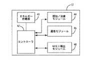
図2は、MRIに誘導される捕捉閾値の変化の検出および補償を行うように構成されたIMD12の一実施形態の機能ブロック図である。IMD12は、エネルギー貯蔵器40、コントローラ42、感知/治療モジュール44、通信モジュール46、およびMRI検出モジュール48を備える。用語「モジュール」は、任意の特定の構造を意味することを意図したものではない。むしろ、「モジュール」は、単一のユニットへ統合された構成部品および回路や機能的に関連した個々の別個の構成部品および回路を意味し得る。加えて、IMD12がIMD12の動作に関連した他の機能を実行するように動作可能な追加の機能モジュールを備えてもよいことが留意される。 FIG. 2 is a functional block diagram of an embodiment of an
エネルギー貯蔵器40は、コントローラ42、感知/治療モジュール44、通信モジュール46、およびMRI検出モジュール48に、動作出力を提供するように動作する。コントローラ42は、感知/治療モジュール44、通信モジュール46、およびMRI検出モジュール48(各々コントローラ42に動作可能に結合され、コントローラ42と通信を行う)を制御するように動作する。例えば、コントローラ42は、ペーシングまたは除細動の刺激など所望の治療を提供するように、または電極36が結合されている組織の捕捉閾値を判定するように感知/治療モジュール44に命令することができる。加えて、コントローラ42は、外部装置19からのデータの送信および/または受信を行うように通信モジュール46に命令することができる。さらにまた、コントローラ42は、MRI走査によって発生される電磁放射の存在または不在を示す信号をMRI検出モジュール48から受信することができる。 The
IMD12は、IMD12のスケジューリング、プロンプト、および/または活性化を行って様々な活動を実行させるように動作するタイミング回路(図示せず)を備えてもよい。一実施形態では、タイミング回路は内部的なタイマまたは発振器であるが、他の実施形態では、タイミング設定は、工程を実行するためのハードワイヤード論理部を含む特定のハードウェア部品によって実行されてもよく、プログラムされたコンピュータ部品とカ
スタムハードウェア部品との任意の組み合わせによって実行されてもよい。The
通信モジュール46は、外部装置19など他の装置との間でテレメトリ信号の送受信を
行うように構成される。他の実施形態では、IMD12は、テレメトリ信号を受信するように構成された1つ以上のトランスデューサと、またテレメトリ信号を送信するための1つ以上のトランスデューサとを備える。通信モジュール46は、テレメトリ信号を介して情報の送信および/または受信を行うことが可能な任意の種類の装置であってよく、無線周波数(RF)送信器、音響トランスデューサ、または誘導トランスデューサを含むが、それらに限定されない。The
感知/治療モジュール44は、IMD12の治療および/または診断機能を実行するように動作する。一実施形態では、感知/治療モジュール44は、心臓ペーシングおよび/または除細動刺激を送達する。感知/治療モジュール44は、特定の種類の生理学的測定または治療を実行するように限定されるものではなく、神経学的な測定および治療など他の種類の生理学的測定および治療を実行するように構成されてもよい。感知/治療モジュール44は、心臓20にペーシング刺激を提供し、その刺激が心臓20の収縮を生じるか否かを感知することによって、心臓20の捕捉閾値を自動的に判定するようにも動作可能である。一部の実施形態では、感知/治療モジュール44は、大きさおよび継続時間のうちの1つ以上の変化する複数のペーシングパルスからなるペーシングパルスのシーケンスを心臓20に送達し、そのペーシングパルスに対する組織の応答を感知して、パルスの継続時間および/または大きさが心臓20を刺激するのに十分に大きいか否かを判定する。心臓20の捕捉閾値を判定するために感知/治療モジュール44に備えられ得る一例の回路構成は、「自動捕捉ペーシング/感知構成(Autocapture Pacing/Sensing Configuration)」と題する米国特許第7,092,756号明細書に開示されている。その全体を引用によって本明細書に援用する。 The sensing /
MRI検出モジュール48は、MRI走査に関連した磁場および/または電磁場の存在を感知する。一部の実施形態では、MRI検出モジュール48は、パワーインダクタおよびコア飽和検出器を備える。MRI場の存在する状態でパワーインダクタが飽和するとパワーインダクタのインダクタンスが低下し、これがコア飽和検出器によって検出される。MRI検出モジュール48における使用に適切なそうした一構成を有する一例のモジュールは、「植込型医療装置におけるMRI検出器(MRI Detector for Implantable Medical Device)」と題する米国特許出願第11/276,159号明細書に開示されている。その全体を引用によって本明細書に援用する。任意の種類のセンサまたは装置が、これに代えてまたはこれに加えてMRI検出モジュール48に組み込まれてよく、係るMRI検出モジュール48はMRI場の存在を検出するように動作可能である。MRI検出モジュール48に備えられるセンサまたは装置の例には、次に限定されないが、ホール効果センサ、磁気トランジスタ、磁気ダイオード、磁気光学センサ、および/または巨大磁気抵抗効果センサが含まれる。 The
MRI検出モジュール48は、MRI場の存在を検出すると、コントローラ42へ信号を送る。コントローラ42は、次いで、IMD12の動作を通常モードの動作からMRIモードの動作に切り替えることができる。これに代えて、IMD12は、例えば、外部装置19を用いることによって、MRIモードの動作に対しプログラムされてよい。MRIモードの動作には、感知を行わない固定レートの徐脈ペーシング(より詳細に以下に記載する)、頻脈治療の無効化、または心臓活動の感知が損なわれ得る高電磁場環境において安全かつ望ましいその他の任意の動作モードが含まれてよい。 When
図3は、図1に示した外部装置19の一実施形態を示す機能ブロック図である。外部装置19は、通信モジュール52、コントローラ54、聴覚/視覚ユーザフィードバック部
56、および入力部58を備える。一部の実施形態では、外部装置19は、介護者がIMD12と通信を行うために使用するための装置である。外部装置19は、インターネット、携帯電話機、および/または情報、プログラム、デバッグ用データ、および更新のダウンロードまたはアップロードを行うための他の有線または無線の手段に接続するためのインタフェースを備えてもよい。FIG. 3 is a functional block diagram showing an embodiment of the
外部装置19の通信モジュール52は、IMD12との間で信号の送受信を行うように構成されている。他の実施形態では、外部装置19は、信号を受信するように構成された1つ以上のトランスデューサと、信号を送信するための1つ以上のトランスデューサとを備える。通信モジュール52は、IMD12の通信モジュール46と通信を行うことの可能な任意の種類の装置であってよく、RF送信器、音響トランスデューサ、または誘導トランスデューサを含むが、それらに限定されない。 The
一部の実施形態では、コントローラ54は、受信した信号の解析、解釈、および/または処理を行うためのプロセッサと、処理した情報および/またはコマンドを内部的な使用のために記憶するためのメモリとを備える。例えば、コントローラ54は、心臓20の捕捉閾値に関連したIMD12からの信号を解析するために用いられてよい。コントローラ54は、デジタル信号プロセッサ(DSP)、フィールドプログラマブルゲートアレイ(FPGA)、特定用途向け集積回路(ASIC)互換デバイス(Xemics社から入手可能なCoolRISCプロセッサなど)、もしくは他のプログラマブルデバイス、および/またはデータの処理、解析、記憶を行うとともに外部装置19の動作を制御するための任意の他のハードウェア部品またはソフトウェアモジュールとして構成されてよい。 In some embodiments, the
ユーザフィードバック部56は、臨床医および/または患者に情報を通信するためのスクリーンまたは表示パネルを備えてよい。一部の実施形態では、このスクリーンまたは表示パネルは、IMD12に関する動作情報を表示するように構成される。例えば、スクリーンまたは表示パネルは、活性なペーシング信号が心臓20を刺激するのに十分であるか否かを評価する際に使用するために、IMD12から受信される心臓20の捕捉閾値を表す視覚情報を表示してもよい。 The
入力部58はインタフェースを備え、このインタフェースを通じて臨床医が情報または外部装置19によって実行されるコマンドを入力することができる。一部の実施形態では、入力部58はキーボードである。例えば、IMD12の感知/治療モジュール44によって実行された捕捉閾値試験に関する情報がユーザフィードバック部56において提供される場合、捕捉閾値試験に関する情報に基づき、臨床医が入力部58を通じて外部装置19に入力を与え、IMD12にペーシング信号構成情報を通信することができる。 The
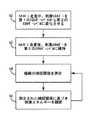
図4は、感知/治療モジュール44によって提供される信号によって心臓20が刺激されることを保証するべく、MRI走査中および走査後にIMD12を制御する方法のフローチャートである。MRI検出モジュール48は、MRI場の存在を検出する。次いで、工程60において、コントローラ42は、心臓20の組織の捕捉を保証するべく、感知/治療モジュール44によって提供される刺激エネルギーを、第1の、MRI前のエネルギー状態から、第2の、MRIモードのエネルギー状態に変化させる。一部の実施形態では、コントローラ42は、MRI場が存在する状態において所定の信号の大きさおよび/または継続時間を有するペーシングパルスを提供するべく感知/治療モジュール44を制御するようにプログラムされてよい。一部の実施形態では、MRI場によって心臓20の捕捉閾値が上昇することがあるので、第2のエネルギー状態は、大きさおよび/または継続時間が第1のエネルギー状態よりも大きい。第2のエネルギー状態はコントローラ42へプログラムされてもよく、第2のエネルギー状態が上述の捕捉検出アルゴリズムを用いて感知/治療モジュール44によって判定されてもよい。これに代えて、第2のエネルギー
状態は外部装置19を介してIMD12に対し提供されてもよい。FIG. 4 is a flowchart of a method for controlling the
MRI検出モジュール48は、MRI場が存在しないことを感知すると(すなわち、MRI走査が完了すると)、コントローラ42へ信号を送り、MRIモードの動作を中止する。これに代えて、コントローラ42は、想定されるMRI走査時間の長さに基づき、所定の期間(例えば、1時間)の後にMRIモードの動作を中止してもよい。いずれの場合にも、工程62において、コントローラ42は、MRI走査の後、感知/治療モジュール44によって提供される刺激エネルギーを第2のエネルギー状態に維持する。これは、心臓20の組織はMRI場の影響から即座に回復しないので、心臓20の捕捉閾値がMRI走査の後にも上昇したままの場合があるからである。これによって、組織が依然としてMRI走査による影響を受けている間に適切なペーシングが維持されることが保証される。 When the
工程64において、コントローラ54は、次いで、心臓20の組織の捕捉閾値を測定するように感知/治療モジュール44に命令する。上述のように、感知/治療モジュール44は、大きさおよび/または継続時間の変化する複数のペーシングパルスからなるペーシングパルスのシーケンスを組織に送達し、そのペーシングパルスに対する組織の応答を感知する。感知/治療モジュール44は、MRI検出モジュール48がMRI場が存在しなくなったことを感知した時からプログラムされた期間の後に、またはMRI場が最後に検出された時とは無関係なプログラムされた期間の後に、自動的に捕捉閾値試験を実行してよい。これに代えて、感知/治療モジュール44は、外部装置19からの信号に応じて捕捉閾値試験を実行してもよい。外部装置19を制御する医療関係者が、捕捉閾値試験中に感知/治療モジュール44によって発生した信号に基づき、手動で適切な捕捉閾値を決定してもよい。捕捉閾値の決定に成功しない場合、感知/治療モジュール44は刺激エネルギーを第2のエネルギー状態に維持する。 In
感知/治療モジュール44が捕捉閾値の判定に成功する場合、工程66において、コントローラ42は、測定された捕捉閾値に基づき心臓20のペーシングを行うために提供される刺激エネルギーを調節するべく感知/治療モジュール44を制御する。これは、IMD12によって自動的に実行されてもよく、外部装置19によって提供される信号に応じて実行されてもよい。したがって、第2のエネルギー状態(すなわち、MRIモードの刺激の状態)から捕捉閾値が低下したと感知/治療モジュール44が判定する場合、コントローラ42は、低下した捕捉閾値に対応するように刺激パルスのエネルギー状態(すなわち、大きさおよび/または継続時間)を低下させる。これによって、エネルギー貯蔵器40に対する引出の最小化が保証されると同時に、心臓20に対して刺激用に適正なエネルギーおよびペースングの大きさが提供されることが保証される。 If the sensing /
一部の実施形態では、生理学的イベントが発生するまで、IMD12によって工程64,66が反復される。例えば、工程64,66は、捕捉閾値が、第1の、MRI前の刺激エネルギー状態に回復するまで、定期的にまたは断続的に反復されてよい。これによって、心臓20がMRI場による影響を受けなくなるまで、IMD12が適正なペーシング刺激を提供することが保証される。別の例として、工程64,66は、捕捉閾値がプログラムされた回数の捕捉閾値試験について一定となるまで反復されてよい。したがって、捕捉閾値が第1の、MRI前の刺激エネルギー状態に復帰しない場合でも、IMD12は組織を刺激するのに十分なレベルでペーシングパルスを提供するように動作する。In some embodiments, steps64 and 66 are repeated by the
要約すると、本発明は、植込型医療装置から送達される組織を刺激するためのエネルギーを制御することに関する。核磁気共鳴映像法(MRI)走査中、組織の刺激用に送達されるエネルギーは第1のエネルギー状態から第2のエネルギー状態に変化させられる。送達されるエネルギーは、MRI走査後、第2のエネルギー状態に維持される。次いで、組織の捕捉閾値が測定され、測定された組織の捕捉閾値に基づき、組織に送達されるエネル
ギーのレベルが調節される。MRI走査の後に捕捉閾値を監視することによって、植込型医療装置は、組織が依然としてMRI走査による影響を受けているときに組織を刺激するのに十分なレベルのエネルギーを送達する。In summary, the present invention relates to controlling energy for stimulating tissue delivered from an implantable medical device. During a nuclear magnetic resonance imaging (MRI) scan, the energy delivered for tissue stimulation is changed from a first energy state to a second energy state. The delivered energy is maintained in the second energy state after the MRI scan. The tissue capture threshold is then measured and the level of energy delivered to the tissue is adjusted based on the measured tissue capture threshold. By monitoring the capture threshold after the MRI scan, the implantable medical device delivers a level of energy sufficient to stimulate the tissue when the tissue is still affected by the MRI scan.
本発明の範囲から逸脱することなく、記載の例示的な実施形態に対し、様々な変更および追加を行うことが可能である。上述の実施形態では特定の特徴を参照しているが、本発明の範囲には、異なる特徴の組み合わせを有する実施形態や、記載の特徴の必ずしもすべてを含まない実施形態が含まれる。例えば、本発明では心臓ペーシングに関して記載したが、本発明の原理は、神経学的な治療システムなど、MRI場によって変更され得る刺激特性を有する他の種類のシステムにも適用可能である。加えて、記載のシステムでは組織を刺激するために電気信号を用いているが、組織に対するMRI場の影響を補償するために化学的な刺激など他の種類の制御因子を用いてもよい。したがって、本発明の範囲には、特許請求の範囲内にあるそのような代替、変更、および変形のすべてや、その均等物が含まれることが意図される。 Various changes and additions can be made to the described exemplary embodiments without departing from the scope of the present invention. Although specific features are referred to in the above-described embodiments, the scope of the present invention includes embodiments having a combination of different features and embodiments that do not necessarily include all of the described features. For example, although the present invention has been described with reference to cardiac pacing, the principles of the present invention are applicable to other types of systems having stimulation characteristics that can be altered by an MRI field, such as a neurological treatment system. In addition, although the described system uses electrical signals to stimulate the tissue, other types of control factors such as chemical stimuli may be used to compensate for the effects of the MRI field on the tissue. Accordingly, the scope of the invention is intended to embrace all such alternatives, modifications, and variations that fall within the scope of the claims and their equivalents.
Claims (12)
Translated fromJapanese身体組織の電気刺激用に適合された電極を有するリードと、
前記リードを通じて組織の電気活動に基づく信号を受信するように動作する感知回路と、
前記リードを通じた前記組織への電気刺激送達用の治療回路と、を備え、
感知回路および治療回路は前記組織の捕捉閾値を測定するようにさらに動作し、
前記植込型医療装置は、
核磁気共鳴映像法走査場を検出するように動作する磁場検出回路と、
制御回路であって、磁場検出回路が前記核磁気共鳴映像法走査場を検出するとき、組織の刺激用に治療回路によって送達されるエネルギーを通常のエネルギー状態から核磁気共鳴映像法モードのエネルギー状態に設定し、磁場検出回路が前記核磁気共鳴映像法走査場を検出しなくなった後の一定の期間、治療回路によって送達されるエネルギーを前記核磁気共鳴映像法モードのエネルギーレベルに維持し、前記期間の後、測定された前記組織の捕捉閾値に基づき、送達されるエネルギーを調節するように動作する制御回路と、をさらに備える植込型医療装置。In implantable medical devices,
A lead having electrodes adapted for electrical stimulation of body tissue;
A sensing circuit operable to receive a signal based on tissue electrical activity through the lead;
A treatment circuit for electrical stimulation delivery to the tissue through the lead,
The sensing circuit and the treatment circuit are further operative to measure a capture threshold for the tissue;
The implantable medical device is:
And the magnetic field detection circuit operable to detect a nuclear magnetic resonance imagingHohashi査場,
A control circuit,wherein when the magnetic field detection circuitdetects the nuclear magnetic resonance imaging scanning field, the energy delivered by the treatment circuit for tissue stimulation is changed from a normal energy state to an energy state in anuclear magnetic resonance imaging mode. And maintaining the energy delivered by the therapy circuit at the energy level of thenuclear magnetic resonance imaging mode for a period of time after themagnetic field detection circuit no longer detects thenuclear magnetic resonance imaging scan field, An implantable medical device further comprising a control circuit operable to adjust energy delivered based on the measured tissue capture threshold after a period of time.
る、請求項1に記載の植込型医療装置。The implantable medical device according to claim 1, wherein the sensing circuit, the treatment circuit, the magnetic field detection circuit, and the control circuit are provided in a pulse generator.
核磁気共鳴映像法走査中、植込型医療装置によって送達されるエネルギーを第1のエネルギー状態から第2のエネルギー状態に変化させるエネルギー変化工程と、
前記核磁気共鳴映像法走査後に、前記送達されるエネルギーを第2のエネルギー状態に維持するエネルギー状態維持工程と、
組織の捕捉閾値を表す捕捉閾値信号を受信する閾値受信工程と、
受信した前記捕捉閾値信号に基づき、送達されるエネルギーを調節するエネルギー調節工程と、を備える方法。In a method of controlling energy delivered from an implantable medical device,
And energy change step of changing the nuclear magnetic resonance imagingHohashi査中, the energy delivered by the implantable medical device from a first energy state into the second energy state,
An energy state maintaining step of maintaining the delivered energy in a second energy state after thenuclear magnetic resonance imaging scan;
A threshold receiving step of receiving the capture threshold signal representing the capture threshold of theorganization,
Adjusting the energy delivered based on the received capture threshold signal.
Applications Claiming Priority (5)
| Application Number | Priority Date | Filing Date | Title |
|---|---|---|---|
| US10202708P | 2008-10-02 | 2008-10-02 | |
| US61/102,027 | 2008-10-02 | ||
| US12/568,433 | 2009-09-28 | ||
| US12/568,433US8571661B2 (en) | 2008-10-02 | 2009-09-28 | Implantable medical device responsive to MRI induced capture threshold changes |
| PCT/US2009/059093WO2010039877A1 (en) | 2008-10-02 | 2009-09-30 | Implantable medical device responsive to mri induced capture threshold changes |
Publications (2)
| Publication Number | Publication Date |
|---|---|
| JP2012504468A JP2012504468A (en) | 2012-02-23 |
| JP5329669B2true JP5329669B2 (en) | 2013-10-30 |
Family
ID=41395845
Family Applications (1)
| Application Number | Title | Priority Date | Filing Date |
|---|---|---|---|
| JP2011530200AExpired - Fee RelatedJP5329669B2 (en) | 2008-10-02 | 2009-09-30 | Implantable medical device responsive to changes in capture threshold induced by MRI |
Country Status (4)
| Country | Link |
|---|---|
| US (2) | US8571661B2 (en) |
| EP (1) | EP2355895A1 (en) |
| JP (1) | JP5329669B2 (en) |
| WO (1) | WO2010039877A1 (en) |
Families Citing this family (26)
| Publication number | Priority date | Publication date | Assignee | Title |
|---|---|---|---|---|
| WO2002090300A2 (en)* | 2001-05-04 | 2002-11-14 | Xencor | Nucleic acids and proteins with thioredoxin reductase activity |
| US8014867B2 (en) | 2004-12-17 | 2011-09-06 | Cardiac Pacemakers, Inc. | MRI operation modes for implantable medical devices |
| US8086321B2 (en) | 2007-12-06 | 2011-12-27 | Cardiac Pacemakers, Inc. | Selectively connecting the tip electrode during therapy for MRI shielding |
| US8032228B2 (en) | 2007-12-06 | 2011-10-04 | Cardiac Pacemakers, Inc. | Method and apparatus for disconnecting the tip electrode during MRI |
| US8311637B2 (en)* | 2008-02-11 | 2012-11-13 | Cardiac Pacemakers, Inc. | Magnetic core flux canceling of ferrites in MRI |
| US8160717B2 (en)* | 2008-02-19 | 2012-04-17 | Cardiac Pacemakers, Inc. | Model reference identification and cancellation of magnetically-induced voltages in a gradient magnetic field |
| US8571661B2 (en) | 2008-10-02 | 2013-10-29 | Cardiac Pacemakers, Inc. | Implantable medical device responsive to MRI induced capture threshold changes |
| US8805496B2 (en)* | 2009-01-30 | 2014-08-12 | Medtronic, Inc. | Automatic disablement of an exposure mode of an implantable medical device |
| EP2398553B1 (en)* | 2009-02-19 | 2015-07-22 | Cardiac Pacemakers, Inc. | Systems for providing arrhythmia therapy in mri environments |
| JP5558583B2 (en) | 2009-12-08 | 2014-07-23 | カーディアック ペースメイカーズ, インコーポレイテッド | Implantable medical device including automatic tachycardia detection and control in an MRI environment |
| US20110160567A1 (en)* | 2009-12-31 | 2011-06-30 | Stahmann Jeffrey E | Functional mri cardiac optimization |
| US20110187360A1 (en)* | 2010-02-04 | 2011-08-04 | Maile Keith R | Mri sensor based on the hall effect for crm imd applications |
| US8744578B2 (en)* | 2010-10-29 | 2014-06-03 | Medtronic, Inc. | Staged sensing adjustments by an implantable medical device in the presence of interfering signals |
| US8983606B2 (en) | 2010-10-29 | 2015-03-17 | Medtronic, Inc. | Enhanced sensing by an implantable medical device in the presence of an interfering signal from an external source |
| US10391320B2 (en) | 2011-01-28 | 2019-08-27 | Medtronic, Inc. | Techniques for detecting magnetic resonance imaging field |
| US9138584B2 (en)* | 2011-04-29 | 2015-09-22 | Medtronic, Inc. | Multiphasic pacing in the presence of electromagnetic interference |
| US9095721B2 (en) | 2011-04-29 | 2015-08-04 | Christopher C. Stancer | Unipolar pacing in the presence of electromagnetic interference |
| US9272152B2 (en) | 2011-08-31 | 2016-03-01 | Cardiac Pacemakers, Inc. | Remote programming of MRI settings of an implantable medical device |
| EP2572752A1 (en)* | 2011-09-21 | 2013-03-27 | BIOTRONIK SE & Co. KG | Electrode catheter device |
| US9981124B2 (en) | 2012-04-26 | 2018-05-29 | Medtronic, Inc. | Devices and techniques for detecting magnetic resonance imaging field |
| US9675806B2 (en) | 2012-10-09 | 2017-06-13 | Medtronic, Inc. | Cardiac pacing during medical procedures |
| US9694187B2 (en)* | 2014-07-16 | 2017-07-04 | Cardiac Pacemakers, Inc. | Implantable medical devices and methods including post-procedural system diagnostics |
| EP2990076B1 (en)* | 2014-09-01 | 2016-12-14 | BIOTRONIK SE & Co. KG | Implant with mri device recognition |
| CN114901350A (en)* | 2019-10-23 | 2022-08-12 | 脉冲动力公司 | Methods of planning and delivering cardiac electrical stimulation |
| EP4048381A1 (en)* | 2019-10-23 | 2022-08-31 | Impulse Dynamics NV | Increasing peak vo2 in patients with hf using cardiac contractility modulation stimulation |
| US20230181912A1 (en)* | 2021-12-15 | 2023-06-15 | Medtronic, Inc. | Secondary verification of mri exposure at an implantable medical device |
Family Cites Families (286)
| Publication number | Priority date | Publication date | Assignee | Title |
|---|---|---|---|---|
| US3888260A (en) | 1972-06-28 | 1975-06-10 | Univ Johns Hopkins | Rechargeable demand inhibited cardiac pacer and tissue stimulator |
| US3898995A (en) | 1974-03-25 | 1975-08-12 | James Bernard Dresbach | Noncompetitive pacemaker with programmable unijunction transistors |
| US4091818A (en)* | 1976-08-03 | 1978-05-30 | Research Corporation | Cardiac pacing apparatus with electromagnetic interference protection |
| US4379459A (en)* | 1981-04-09 | 1983-04-12 | Medtronic, Inc. | Cardiac pacemaker sense amplifier |
| US4404125A (en) | 1981-10-14 | 1983-09-13 | General Electric Company | Polyphenylene ether resin compositions for EMI electromagnetic interference shielding |
| DE3232478C1 (en)* | 1982-09-01 | 1984-03-01 | Werner Prof. Dr.-Ing. 6301 Wettenberg Irnich | Synchronizable pacemaker |
| US4611127A (en) | 1984-09-20 | 1986-09-09 | Telectronics N.V. | Electronic sensor for static magnetic field |
| US4729376A (en)* | 1985-05-28 | 1988-03-08 | Cordis Corporation | Cardiac pacer and method providing means for periodically determining capture threshold and adjusting pulse output level accordingly |
| US5038785A (en) | 1985-08-09 | 1991-08-13 | Picker International, Inc. | Cardiac and respiratory monitor with magnetic gradient noise elimination |
| US4694837A (en) | 1985-08-09 | 1987-09-22 | Picker International, Inc. | Cardiac and respiratory gated magnetic resonance imaging |
| US4869970A (en) | 1986-07-14 | 1989-09-26 | Shipley Company Inc. | Radiation attenuation shielding |
| US4751110A (en) | 1986-07-14 | 1988-06-14 | Shipley Company Inc. | Radiation attenuation shielding |
| FR2604286B1 (en) | 1986-09-18 | 1988-11-10 | Mayer Ferdy | WAVE PROPAGATION STRUCTURES FOR SUPPRESSION OF OVERVOLTAGES AND ABSORPTION OF TRANSIENTS |
| US4779617A (en) | 1986-10-06 | 1988-10-25 | Telectronics N.V. | Pacemaker noise rejection system |
| US4823075A (en) | 1987-10-13 | 1989-04-18 | General Electric Company | Current sensor using hall-effect device with feedback |
| EP0331959B1 (en) | 1988-02-29 | 1994-12-28 | Pacesetter AB | Bipolar filtered feedthrough terminal |
| US4934366A (en) | 1988-09-01 | 1990-06-19 | Siemens-Pacesetter, Inc. | Feedthrough connector for implantable medical device |
| US5197468A (en)* | 1990-02-13 | 1993-03-30 | Proctor Paul W | Device for protecting an electronic prosthesis from adverse effects of RF and/or electrostatic energy |
| US5036768A (en)* | 1990-02-13 | 1991-08-06 | Dow Robert L | Attenuator for dissipating electromagnetic and electrostatic energy |
| US5243911A (en) | 1990-09-18 | 1993-09-14 | Dow Robert L | Attenuator for protecting electronic equipment from undesired exposure to RF energy and/or lightning |
| US5075039A (en) | 1990-05-31 | 1991-12-24 | Shipley Company Inc. | Platable liquid film forming coating composition containing conductive metal sulfide coated inert inorganic particles |
| US5120578A (en) | 1990-05-31 | 1992-06-09 | Shipley Company Inc. | Coating composition |
| US5076841A (en) | 1990-05-31 | 1991-12-31 | Shipley Company Inc. | Coating composition |
| US5288313A (en)* | 1990-05-31 | 1994-02-22 | Shipley Company Inc. | Electroless plating catalyst |
| US5217010A (en) | 1991-05-28 | 1993-06-08 | The Johns Hopkins University | Ecg amplifier and cardiac pacemaker for use during magnetic resonance imaging |
| US5187136A (en)* | 1991-06-17 | 1993-02-16 | Ethyl Corporation | Asymmetric hydrogenation of aromatic-substituted olefins using organorhenium catalyst |
| DE59106870D1 (en)* | 1991-08-26 | 1995-12-14 | Pacesetter Ab | Magnetic field detector. |
| EP0530006A1 (en) | 1991-08-26 | 1993-03-03 | Medtronic, Inc. | Magnetic field sensor for implantable medical device |
| US5181511A (en) | 1991-10-21 | 1993-01-26 | Telectronics Pacing Systems, Inc. | Apparatus and method for antitachycardia pacing using a virtual electrode |
| US5188117A (en)* | 1991-10-25 | 1993-02-23 | Telectronics Pacing Systems, Inc. | Notch filter noise rejection system in a cardiac control device |
| US5391188A (en)* | 1992-05-01 | 1995-02-21 | Medtronic, Inc. | Low cost implantable medical device |
| US5292342A (en)* | 1992-05-01 | 1994-03-08 | Medtronic, Inc. | Low cost implantable medical device |
| SE470397B (en) | 1992-07-06 | 1994-02-14 | Sandvik Ab | Saw blades with radial slots and arcuate recesses for vibration damping |
| EP0590178B1 (en) | 1992-09-29 | 1997-10-29 | Pacesetter AB | Magnetic field detector |
| AU5597194A (en) | 1992-11-24 | 1994-06-22 | Medtronic, Inc. | Implantable medical device with magnetically actuated switch |
| CA2152604C (en)* | 1993-02-01 | 2000-05-09 | Thomas M. Soukup | An implantable electrode |
| US5406444A (en)* | 1993-03-29 | 1995-04-11 | Medtronic, Inc. | Coated tantalum feedthrough pin |
| FR2704131B1 (en) | 1993-04-22 | 1995-06-30 | Odam | Sensor device for electrocardiogram. |
| US5345362A (en) | 1993-04-29 | 1994-09-06 | Medtronic, Inc. | Portable computer apparatus with articulating display panel |
| SE9301855D0 (en) | 1993-06-01 | 1993-06-01 | Siemens-Elema Ab | MEDICAL SYSTEM |
| US5325728A (en) | 1993-06-22 | 1994-07-05 | Medtronic, Inc. | Electromagnetic flow meter |
| AU673109B2 (en) | 1993-12-09 | 1996-10-24 | Medtronic, Inc. | Cardiac pacemaker with triggered magnet modes |
| SE9400622D0 (en) | 1994-02-23 | 1994-02-23 | Siemens Elema Ab | Medical implant |
| US5618208A (en)* | 1994-06-03 | 1997-04-08 | Siemens Medical Systems, Inc. | Fully insulated, fully shielded electrical connector arrangement |
| US5470345A (en) | 1994-06-16 | 1995-11-28 | Medtronic, Inc. | Implantable medical device with multi-layered ceramic enclosure |
| US5782891A (en) | 1994-06-16 | 1998-07-21 | Medtronic, Inc. | Implantable ceramic enclosure for pacing, neurological, and other medical applications in the human body |
| US6217800B1 (en) | 1996-01-25 | 2001-04-17 | Sgl Technic, Inc. | Graphite foam material and method of making same |
| SE9403188D0 (en)* | 1994-09-22 | 1994-09-22 | Siemens Elema Ab | Magnetic field detector on a medical implant |
| US5827997A (en) | 1994-09-30 | 1998-10-27 | Chung; Deborah D. L. | Metal filaments for electromagnetic interference shielding |
| US5735884A (en)* | 1994-10-04 | 1998-04-07 | Medtronic, Inc. | Filtered feedthrough assembly for implantable medical device |
| AU3299995A (en) | 1994-10-04 | 1996-04-18 | Medtronic, Inc. | Protective feedthrough |
| US5647379A (en) | 1994-11-22 | 1997-07-15 | Ventritex, Inc. | Correlator based electromagnetic interference responsive control system useful in medical devices |
| SE9404374D0 (en) | 1994-12-15 | 1994-12-15 | Pacesetter Ab | magnetic field detector |
| FR2728799B1 (en) | 1994-12-30 | 1997-03-28 | Ela Medical Sa | ACTIVE IMPLANTABLE DEVICE, IN PARTICULAR STIMULATOR OR CARDIAC DEFIBRILLATOR, PROVIDED WITH MEANS OF PROTECTION AGAINST ELECTROMAGNETIC DISTURBANCES OF EXTERNAL ORIGIN |
| US5527348A (en) | 1995-02-03 | 1996-06-18 | Medtronic, Inc. | Magnetically permeable E-shield and method of connection thereto |
| US5562714A (en) | 1995-02-03 | 1996-10-08 | Medtronic, Inc. | Magnetic field strength regulator for implant |
| US5523578A (en) | 1995-03-22 | 1996-06-04 | Herskovic; Arnold | Electromagnetic radiation shielding arrangement and method for radiation therapy patients |
| FR2734731B1 (en) | 1995-06-01 | 1997-08-14 | Christian Mounier | METHOD AND DEVICE FOR CARDIAC STIMULATION IN THE PRESENCE OF ELECTROMAGNETIC INTERFERENCE |
| US5697958A (en) | 1995-06-07 | 1997-12-16 | Intermedics, Inc. | Electromagnetic noise detector for implantable medical devices |
| US5722998A (en)* | 1995-06-07 | 1998-03-03 | Intermedics, Inc. | Apparatus and method for the control of an implantable medical device |
| US5814090A (en) | 1995-06-07 | 1998-09-29 | Angeion Corporation | Implantable medical device having heat-shrink conforming shield |
| US5749910A (en)* | 1995-06-07 | 1998-05-12 | Angeion Corporation | Shield for implantable cardioverter defibrillator |
| US5592939A (en) | 1995-06-14 | 1997-01-14 | Martinelli; Michael A. | Method and system for navigating a catheter probe |
| US5764052A (en) | 1995-06-16 | 1998-06-09 | Pacesetter, Inc. | Coil return energy measurement magnetic field sensor and method thereof |
| US5607458A (en)* | 1995-07-13 | 1997-03-04 | Pacesetter, Inc. | Safety optimization in microprocessor controlled implantable devices |
| WO1997012645A1 (en) | 1995-10-03 | 1997-04-10 | Intermedics, Inc. | Feedthrough assembly with transient voltage suppressor and emi filter for implantable medical devices |
| US5662697A (en) | 1995-10-17 | 1997-09-02 | Pacesetter, Inc. | Transvenous internal cardiac defibrillation apparatus having lead and electrode providing even distribution of electrical charge |
| US5650759A (en) | 1995-11-09 | 1997-07-22 | Hittman Materials & Medical Components, Inc. | Filtered feedthrough assembly having a mounted chip capacitor for medical implantable devices and method of manufacture therefor |
| US5620476A (en)* | 1995-11-13 | 1997-04-15 | Pacesetter, Inc. | Implantable medical device having shielded and filtered feedthrough assembly and methods for making such assembly |
| US5978204A (en) | 1995-11-27 | 1999-11-02 | Maxwell Energy Products, Inc. | Capacitor with dual element electrode plates |
| US5751539A (en)* | 1996-04-30 | 1998-05-12 | Maxwell Laboratories, Inc. | EMI filter for human implantable heart defibrillators and pacemakers |
| US5853375A (en) | 1995-11-29 | 1998-12-29 | Medtronic, Inc. | Guide wire extension peg and hole with 90 degree latch |
| US5727552A (en)* | 1996-01-11 | 1998-03-17 | Medtronic, Inc. | Catheter and electrical lead location system |
| US5714536A (en)* | 1996-01-11 | 1998-02-03 | Xerox Corporation | Magnetic nanocompass compositions and processes for making and using |
| US5637083A (en) | 1996-01-19 | 1997-06-10 | Pudenz-Schulte Medical Research Corporation | Implantable adjustable fluid flow control valve |
| US5687735A (en) | 1996-03-28 | 1997-11-18 | Hewlett-Packard Company | Robust time-diversity filter and method for removing electromagnetic interference |
| US5776168A (en) | 1996-04-03 | 1998-07-07 | Medtronic, Inc. | EGM recording system for implantable medical device |
| US6161046A (en) | 1996-04-09 | 2000-12-12 | Maniglia; Anthony J. | Totally implantable cochlear implant for improvement of partial and total sensorineural hearing loss |
| US5869078A (en)* | 1996-04-25 | 1999-02-09 | Medtronic Inc. | Implantable variable permeability drug infusion techniques |
| US5817130A (en) | 1996-05-03 | 1998-10-06 | Sulzer Intermedics Inc. | Implantable cardiac cardioverter/defibrillator with EMI suppression filter with independent ground connection |
| US5800496A (en) | 1996-06-24 | 1998-09-01 | Medtronic, Inc. | Medical electrical lead having a crush resistant lead body |
| US5877630A (en)* | 1996-08-16 | 1999-03-02 | Credence Technologies, Inc. | System and method for protecting an electronic device from electromagnetic radiation interference |
| US5683434A (en) | 1996-12-06 | 1997-11-04 | Pacesetter, Inc. | Microstrip EMI shunt for an implantable medical device |
| US5895980A (en)* | 1996-12-30 | 1999-04-20 | Medical Pacing Concepts, Ltd. | Shielded pacemaker enclosure |
| US6055455A (en)* | 1997-01-06 | 2000-04-25 | Cardiac Pacemakers, Inc. | Filtered feedthrough for an implantable medical device |
| US5766227A (en) | 1997-03-04 | 1998-06-16 | Nappholz; Tibor A. | EMI detection in an implantable pacemaker and the like |
| US6173203B1 (en)* | 1997-04-08 | 2001-01-09 | Survivalink Corpration | Circuit mounting system for automated external defibrillator circuits |
| EP0870517B1 (en) | 1997-04-10 | 2004-06-30 | Greatbatch-Hittman, Incorporated | Filtered feedthrough assembly for medical implantable devices and method of manufacture therefor |
| US6198972B1 (en)* | 1997-04-30 | 2001-03-06 | Medtronic, Inc. | Control of externally induced current in implantable medical devices |
| US5870272A (en)* | 1997-05-06 | 1999-02-09 | Medtronic Inc. | Capacitive filter feedthrough for implantable medical device |
| US5800497A (en) | 1997-07-17 | 1998-09-01 | Medtronic, Inc. | Medical electrical lead with temporarily stiff portion |
| US5964705A (en) | 1997-08-22 | 1999-10-12 | Image-Guided Drug Delivery System, Inc. | MR-compatible medical devices |
| US5905627A (en)* | 1997-09-10 | 1999-05-18 | Maxwell Energy Products, Inc. | Internally grounded feedthrough filter capacitor |
| EP0904741B1 (en) | 1997-09-26 | 2004-12-08 | Koninklijke Philips Electronics N.V. | Apparatus for supporting a surgical instrument |
| US5968854A (en) | 1997-10-03 | 1999-10-19 | Electromagnetic Protection, Inc. | EMI shielding fabric and fabric articles made therefrom |
| US6008980A (en) | 1997-11-13 | 1999-12-28 | Maxwell Energy Products, Inc. | Hermetically sealed EMI feedthrough filter capacitor for human implant and other applications |
| US6643903B2 (en) | 1997-11-13 | 2003-11-11 | Greatbatch-Sierra, Inc. | Process for manufacturing an EMI filter feedthrough terminal assembly |
| US6275369B1 (en) | 1997-11-13 | 2001-08-14 | Robert A. Stevenson | EMI filter feedthough terminal assembly having a capture flange to facilitate automated assembly |
| SE9704520D0 (en)* | 1997-12-04 | 1997-12-04 | Pacesetter Ab | Pacemaker |
| US6032063A (en)* | 1997-12-09 | 2000-02-29 | Vital Connections, Inc. | Distributed resistance leadwire harness assembly for physiological monitoring during magnetic resonance imaging |
| US6662049B1 (en) | 1997-12-17 | 2003-12-09 | Pacesetter, Inc. | Implantable device with a programmable reset mode and method of operation |
| SE9800126D0 (en) | 1998-01-20 | 1998-01-20 | Pacesetter Ab | Implantable medical device |
| US5978710A (en) | 1998-01-23 | 1999-11-02 | Sulzer Intermedics Inc. | Implantable cardiac stimulator with safe noise mode |
| US5959829A (en) | 1998-02-18 | 1999-09-28 | Maxwell Energy Products, Inc. | Chip capacitor electromagnetic interference filter |
| US6295474B1 (en)* | 1998-03-13 | 2001-09-25 | Intermedics Inc. | Defibrillator housing with conductive polymer coating |
| DE69928233T2 (en) | 1998-03-13 | 2006-07-06 | Medtronic, Inc., Minneapolis | FLOWERS AND CONVERTERS |
| US5973906A (en) | 1998-03-17 | 1999-10-26 | Maxwell Energy Products, Inc. | Chip capacitors and chip capacitor electromagnetic interference filters |
| US5871509A (en)* | 1998-04-02 | 1999-02-16 | Pacesetter Ab | Method and apparatus to remove data outliers, produced by external disturbance, in internally measured signals in an implantable cardiac stimulator |
| US6268725B1 (en) | 1998-04-29 | 2001-07-31 | Medtronic, Inc. | Flux-gate magnetometer with drive signal for reducing effects of electromagnetic interference |
| US6270831B2 (en)* | 1998-04-30 | 2001-08-07 | Medquest Products, Inc. | Method and apparatus for providing a conductive, amorphous non-stick coating |
| US6101417A (en) | 1998-05-12 | 2000-08-08 | Pacesetter, Inc. | Implantable electrical device incorporating a magnetoresistive magnetic field sensor |
| US6147301A (en)* | 1998-06-04 | 2000-11-14 | Intel Corporation | Graphite-fiber enhanced molded plastic for electronic enclosures |
| US6134478A (en)* | 1998-06-05 | 2000-10-17 | Intermedics Inc. | Method for making cardiac leads with zone insulated electrodes |
| US5999398A (en) | 1998-06-24 | 1999-12-07 | Avx Corporation | Feed-through filter assembly having varistor and capacitor structure |
| SE9802423D0 (en) | 1998-07-06 | 1998-07-06 | Pascal Medical Ab | Device for the treatment of Meniere's disease and similar ailments |
| US6324431B1 (en) | 1998-07-06 | 2001-11-27 | Abiomed, Inc. | Transcutaneous energy transfer device with magnetic field protected components in secondary coil |
| JP2000058132A (en) | 1998-08-11 | 2000-02-25 | Wilson Greatbatch Ltd | Electrochemical battery having magnetic suitability |
| US6470212B1 (en) | 1998-08-11 | 2002-10-22 | Medtronic, Inc. | Body heat powered implantable medical device |
| US6424234B1 (en) | 1998-09-18 | 2002-07-23 | Greatbatch-Sierra, Inc. | Electromagnetic interference (emi) filter and process for providing electromagnetic compatibility of an electronic device while in the presence of an electromagnetic emitter operating at the same frequency |
| US6245464B1 (en) | 1998-09-21 | 2001-06-12 | Wilson Greatbatch Ltd. | Hermetically sealed lithium-ion secondary electrochemical cell |
| JP2000100475A (en) | 1998-09-21 | 2000-04-07 | Wilson Greatbatch Ltd | Lithium ion secondary electrochemical battery |
| US6701176B1 (en) | 1998-11-04 | 2004-03-02 | Johns Hopkins University School Of Medicine | Magnetic-resonance-guided imaging, electrophysiology, and ablation |
| EP1128764A4 (en) | 1998-11-10 | 2003-06-04 | Compumedics Ltd | fMRI COMPATIBLE ELECTRODE AND ELECTRODE PLACEMENT TECHNIQUES |
| US7092756B2 (en) | 1998-12-08 | 2006-08-15 | Cardiac Pacemakers, Inc. | Autocapture pacing/sensing configuration |
| US6162180A (en) | 1998-12-28 | 2000-12-19 | Medtronic, Inc. | Non-invasive cardiac monitoring system and method with communications interface |
| US6249701B1 (en) | 1999-02-12 | 2001-06-19 | Medtronic, Inc. | Implantable device with automatic sensing adjustment |
| US6192279B1 (en)* | 1999-02-23 | 2001-02-20 | Medtronic, Inc. | Non-invasively maneuverable lead system |
| US6246902B1 (en) | 1999-05-04 | 2001-06-12 | Siemens Medical Systems, Inc. | Lead set filter for a patient monitor |
| US6501988B2 (en) | 2000-12-26 | 2002-12-31 | Cardiac Pacemakers Inc. | Apparatus and method for ventricular rate regularization with biventricular sensing |
| US6607485B2 (en) | 1999-06-03 | 2003-08-19 | Cardiac Intelligence Corporation | Computer readable storage medium containing code for automated collection and analysis of patient information retrieved from an implantable medical device for remote patient care |
| DE19927616A1 (en) | 1999-06-17 | 2000-12-21 | Biotronik Mess & Therapieg | Method and device for distinguishing between electromagnetic interference signals and electromedical scanning signals, in particular of cardiological implants |
| US6288344B1 (en)* | 1999-08-20 | 2001-09-11 | Cardiac Pacemakers, Inc. | Integrated EMI shield utilizing a hybrid edge |
| US6381494B1 (en)* | 1999-08-20 | 2002-04-30 | Cardiac Pacemakers, Inc. | Response to ambient noise in implantable pulse generator |
| US6235038B1 (en)* | 1999-10-28 | 2001-05-22 | Medtronic Surgical Navigation Technologies | System for translation of electromagnetic and optical localization systems |
| AU1764901A (en) | 1999-11-17 | 2001-05-30 | Amiram Katz | Protective gear for individuals with implanted electronic devices and others exposed to hazardous electromagnetic radiation |
| US6358281B1 (en) | 1999-11-29 | 2002-03-19 | Epic Biosonics Inc. | Totally implantable cochlear prosthesis |
| EP1109180B1 (en) | 1999-12-14 | 2012-02-08 | Greatbatch Ltd. | Emi Filter feedthrough terminal assembly |
| US6503964B2 (en)* | 2000-01-11 | 2003-01-07 | Cool Options, Inc. | Polymer composition with metal coated carbon flakes |
| US20010018123A1 (en) | 2000-01-28 | 2001-08-30 | Kenji Furumori | Electromagnetic wave shielding device |
| WO2001054578A1 (en) | 2000-01-31 | 2001-08-02 | Pearlman Justin D | Multivariate cardiac monitor |
| EP1264377A4 (en) | 2000-02-03 | 2008-10-29 | X2Y Attenuators Llc | Passive electrostatic shielding structure for electrical circuitry and energy conditioning with outer partial-shielded energy pathways |
| US6631555B1 (en) | 2000-02-08 | 2003-10-14 | Cardiac Pacemakers, Inc. | Method of thin film deposition as an active conductor |
| US6414835B1 (en) | 2000-03-01 | 2002-07-02 | Medtronic, Inc. | Capacitive filtered feedthrough array for an implantable medical device |
| US6580947B1 (en) | 2000-03-10 | 2003-06-17 | Medtronic, Inc. | Magnetic field sensor for an implantable medical device |
| FR2806808B1 (en) | 2000-03-24 | 2002-05-24 | Ela Medical Sa | CIRCUIT FOR DETECTING THE PRESENCE OF A PERMANENT MAGNET IN THE VICINITY OF AN ACTIVE MEDICAL DEVICE, IN PARTICULAR A CARDIAC PACEMAKER, DEFIBRILLATOR, CARDIOVERTER AND/OR MULTI-SITE DEVICE |
| US6795730B2 (en)* | 2000-04-20 | 2004-09-21 | Biophan Technologies, Inc. | MRI-resistant implantable device |
| US8527046B2 (en) | 2000-04-20 | 2013-09-03 | Medtronic, Inc. | MRI-compatible implantable device |
| US6925328B2 (en)* | 2000-04-20 | 2005-08-02 | Biophan Technologies, Inc. | MRI-compatible implantable device |
| US6510345B1 (en)* | 2000-04-24 | 2003-01-21 | Medtronic, Inc. | System and method of bridging a transreceiver coil of an implantable medical device during non-communication periods |
| US20030036774A1 (en)* | 2000-06-01 | 2003-02-20 | Chris Maier | Switching apparatus for monitoring catherter signals and performing cardioversion defibrillations |
| US6459935B1 (en) | 2000-07-13 | 2002-10-01 | Avx Corporation | Integrated filter feed-thru |
| US6539253B2 (en)* | 2000-08-26 | 2003-03-25 | Medtronic, Inc. | Implantable medical device incorporating integrated circuit notch filters |
| US6720245B2 (en) | 2000-09-07 | 2004-04-13 | Interuniversitair Microelektronica Centrum (Imec) | Method of fabrication and device for electromagnetic-shielding structures in a damascene-based interconnect scheme |
| US6882248B2 (en) | 2000-09-07 | 2005-04-19 | Greatbatch-Sierra, Inc. | EMI filtered connectors using internally grounded feedthrough capacitors |
| US6529103B1 (en) | 2000-09-07 | 2003-03-04 | Greatbatch-Sierra, Inc. | Internally grounded feedthrough filter capacitor with improved ground plane design for human implant and other applications |
| US6631290B1 (en) | 2000-10-25 | 2003-10-07 | Medtronic, Inc. | Multilayer ceramic electrodes for sensing cardiac depolarization signals |
| US6626937B1 (en) | 2000-11-14 | 2003-09-30 | Advanced Cardiovascular Systems, Inc. | Austenitic nitinol medical devices |
| WO2002056761A2 (en) | 2000-11-17 | 2002-07-25 | Noveon Ip Holdings Corp. | Acoustic-based remotely interrrogated diagnostic implant device and system |
| US6522920B2 (en)* | 2000-12-11 | 2003-02-18 | Pacesetter, Inc. | System and method of protecting transformer-driven switches from external magnetic fields |
| US6738667B2 (en)* | 2000-12-28 | 2004-05-18 | Medtronic, Inc. | Implantable medical device for treating cardiac mechanical dysfunction by electrical stimulation |
| EP1362367A2 (en)* | 2001-01-23 | 2003-11-19 | Quantum Polymer Technologies, Inc. | Conductive polymer materials and methods for their manufacture and use |
| US20020116033A1 (en) | 2001-02-20 | 2002-08-22 | Wilson Greatbatch | Controllable, wearable MRI-compatible cardiac pacemaker with pulse carrying photonic catheter and VOO functionality |
| US6949929B2 (en) | 2003-06-24 | 2005-09-27 | Biophan Technologies, Inc. | Magnetic resonance imaging interference immune device |
| US20020116034A1 (en) | 2001-02-20 | 2002-08-22 | Victor Miller | Controllable, wearable MRI-compatible pacemaker with power carrying photonic catheter and VOO functionality |
| US20020116028A1 (en) | 2001-02-20 | 2002-08-22 | Wilson Greatbatch | MRI-compatible pacemaker with pulse carrying photonic catheter providing VOO functionality |
| GB0104910D0 (en) | 2001-02-28 | 2001-04-18 | Ibm | Devices to reduce electro-magnetic field radiation |
| US20020162605A1 (en) | 2001-03-05 | 2002-11-07 | Horton Joseph A. | Bulk metallic glass medical instruments, implants, and methods of using same |
| US6488704B1 (en) | 2001-05-07 | 2002-12-03 | Biomed Solutions, Llc | Implantable particle measuring apparatus |
| US6750055B1 (en) | 2001-03-07 | 2004-06-15 | Biomed Solutions Llc | Implantable artificial organ and physiological monitoring system |
| US6452564B1 (en) | 2001-03-09 | 2002-09-17 | The United States Of America As Represented By The Secretary Of The Navy | RF surface wave attenuating dielectric coatings composed of conducting, high aspect ratio biologically-derived particles in a polymer matrix |
| US6901292B2 (en) | 2001-03-19 | 2005-05-31 | Medtronic, Inc. | Control of externally induced current in an implantable pulse generator |
| US6889086B2 (en) | 2001-04-06 | 2005-05-03 | Cardiac Pacemakers, Inc. | Passive telemetry system for implantable medical device |
| WO2002092161A1 (en) | 2001-05-10 | 2002-11-21 | Biophan, Llc | Miniaturized particle analyzer |
| US6545854B2 (en)* | 2001-05-25 | 2003-04-08 | Presidio Components, Inc. | Fringe-field non-overlapping-electrodes discoidal feed-through ceramic filter capacitor with high breakdown voltage |
| US20030120197A1 (en) | 2001-05-28 | 2003-06-26 | Takashi Kaneko | Composite material for medical applications, tube for medical applications and medical instrument |
| US6456481B1 (en) | 2001-05-31 | 2002-09-24 | Greatbatch-Sierra, Inc. | Integrated EMI filter-DC blocking capacitor |
| US6567259B2 (en)* | 2001-05-31 | 2003-05-20 | Greatbatch-Sierra, Inc. | Monolithic ceramic capacitor with barium titinate dielectric curie point optimized for active implantable medical devices operating at 37° C. |
| US6496714B1 (en) | 2001-07-20 | 2002-12-17 | Koninklijke Philips Electronics N.V. | RF-safe invasive device |
| US7118693B2 (en) | 2001-07-27 | 2006-10-10 | Eikos, Inc. | Conformal coatings comprising carbon nanotubes |
| US6512666B1 (en)* | 2001-08-21 | 2003-01-28 | Delware Capital Formation, Inc. | High current filter feed-through capacitor |
| US7054686B2 (en)* | 2001-08-30 | 2006-05-30 | Biophan Technologies, Inc. | Pulsewidth electrical stimulation |
| US6731979B2 (en)* | 2001-08-30 | 2004-05-04 | Biophan Technologies Inc. | Pulse width cardiac pacing apparatus |
| US6595756B2 (en) | 2001-09-07 | 2003-07-22 | Medtronic Minimed, Inc. | Electronic control system and process for electromagnetic pump |
| US6997921B2 (en) | 2001-09-07 | 2006-02-14 | Medtronic Minimed, Inc. | Infusion device and driving mechanism for same |
| US6538191B1 (en)* | 2001-09-26 | 2003-03-25 | Biomed Solutions, Llc | Photocell with fluorescent conversion layer |
| US20030081370A1 (en)* | 2001-10-15 | 2003-05-01 | Haskell Donald K. | Apparatus and process for the control of electromagnetic fields on the surface of EMI filter capacitors |
| US6555745B1 (en)* | 2001-10-19 | 2003-04-29 | Medtronic, Inc. | Electrical interconnect between an articulating display and a PC based planar board |
| US6988001B2 (en)* | 2001-10-31 | 2006-01-17 | Biophan Technologies, Inc. | Hermetic component housing for photonic catheter |
| US7076283B2 (en)* | 2001-10-31 | 2006-07-11 | Medtronic, Inc. | Device for sensing cardiac activity in an implantable medical device in the presence of magnetic resonance imaging interference |
| US6871091B2 (en)* | 2001-10-31 | 2005-03-22 | Medtronic, Inc. | Apparatus and method for shunting induced currents in an electrical lead |
| US6944489B2 (en)* | 2001-10-31 | 2005-09-13 | Medtronic, Inc. | Method and apparatus for shunting induced currents in an electrical lead |
| US6959214B2 (en)* | 2001-11-28 | 2005-10-25 | Medtronic, Inc. | Implantable medical device for measuring mechanical heart function |
| US20030109901A1 (en) | 2001-12-11 | 2003-06-12 | Wilson Greatbatch | Photonic pacemaker-cardiac monitor |
| US7729776B2 (en) | 2001-12-19 | 2010-06-01 | Cardiac Pacemakers, Inc. | Implantable medical device with two or more telemetry systems |
| US6993393B2 (en) | 2001-12-19 | 2006-01-31 | Cardiac Pacemakers, Inc. | Telemetry duty cycle management system for an implantable medical device |
| US6799067B2 (en) | 2001-12-26 | 2004-09-28 | Advanced Cardiovascular Systems, Inc. | MRI compatible guide wire |
| US6490148B1 (en) | 2002-01-02 | 2002-12-03 | Greatbatch-Hittman, Incorporated | Installation of filter capacitors into feedthroughs for implantable medical devices |
| US20030130701A1 (en) | 2002-01-04 | 2003-07-10 | Victor Miller | Opto-electric coupling device for photonic pacemakers and other opto-electric medical stimulation equipment |
| US20030130700A1 (en) | 2002-01-04 | 2003-07-10 | Victor Miller | Optical pulse generator for battery powered photonic pacemakers and other light driven medical stimulation equipment |
| US7060030B2 (en) | 2002-01-08 | 2006-06-13 | Cardiac Pacemakers, Inc. | Two-hop telemetry interface for medical device |
| US6506972B1 (en)* | 2002-01-22 | 2003-01-14 | Nanoset, Llc | Magnetically shielded conductor |
| US6906256B1 (en)* | 2002-01-22 | 2005-06-14 | Nanoset, Llc | Nanomagnetic shielding assembly |
| EP1476882A4 (en) | 2002-01-22 | 2007-01-17 | Nanoset Llc | Nanomagnetically shielded substrate |
| JPWO2003063258A1 (en) | 2002-01-24 | 2005-05-26 | 三菱電機株式会社 | Semiconductor device |
| US6968236B2 (en) | 2002-01-28 | 2005-11-22 | Biophan Technologies, Inc. | Ceramic cardiac electrodes |
| EP1469910B1 (en) | 2002-01-29 | 2006-12-06 | Medtronic, Inc. | Conditioning of coupled electromagnetic signals on a lead |
| US20030144718A1 (en) | 2002-01-29 | 2003-07-31 | Zeijlemaker Volkert A. | Method and apparatus for shielding coating for MRI resistant electrode systems |
| US6985775B2 (en) | 2002-01-29 | 2006-01-10 | Medtronic, Inc. | Method and apparatus for shunting induced currents in an electrical lead |
| US7050855B2 (en) | 2002-01-29 | 2006-05-23 | Medtronic, Inc. | Medical implantable system for reducing magnetic resonance effects |
| US20030144719A1 (en) | 2002-01-29 | 2003-07-31 | Zeijlemaker Volkert A. | Method and apparatus for shielding wire for MRI resistant electrode systems |
| US20030144706A1 (en) | 2002-01-29 | 2003-07-31 | Funke Hermann D. | Method and apparatus for controlling an implantable medical device in response to the presence of a magnetic field and/or high frequency radiation interference signals |
| US6937906B2 (en) | 2002-01-29 | 2005-08-30 | Medtronic, Inc. | Method and apparatus for detecting static magnetic fields |
| US20030144720A1 (en)* | 2002-01-29 | 2003-07-31 | Villaseca Eduardo H. | Electromagnetic trap for a lead |
| US7082328B2 (en)* | 2002-01-29 | 2006-07-25 | Medtronic, Inc. | Methods and apparatus for controlling a pacing system in the presence of EMI |
| US6985773B2 (en) | 2002-02-07 | 2006-01-10 | Cardiac Pacemakers, Inc. | Methods and apparatuses for implantable medical device telemetry power management |
| US7236821B2 (en) | 2002-02-19 | 2007-06-26 | Cardiac Pacemakers, Inc. | Chronically-implanted device for sensing and therapy |
| WO2003070098A2 (en) | 2002-02-19 | 2003-08-28 | Biophan Technologies, Inc. | Magnetic resonance imaging capable catheter assembly |
| EP1488434B1 (en) | 2002-02-28 | 2012-12-12 | Greatbatch Ltd. | Emi feedthrough filter terminal assembly utilizing hermetic seal for electrical attachment between lead wires and capacitor |
| US20040005483A1 (en)* | 2002-03-08 | 2004-01-08 | Chhiu-Tsu Lin | Perovskite manganites for use in coatings |
| US6640137B2 (en) | 2002-03-15 | 2003-10-28 | Biomed Solutions Llc | Biothermal power source for implantable devices |
| US20030191505A1 (en) | 2002-04-09 | 2003-10-09 | Mark Gryzwa | Magnetic structure for feedthrough filter assembly |
| US6711440B2 (en) | 2002-04-11 | 2004-03-23 | Biophan Technologies, Inc. | MRI-compatible medical device with passive generation of optical sensing signals |
| US20030204217A1 (en) | 2002-04-25 | 2003-10-30 | Wilson Greatbatch | MRI-safe cardiac stimulation device |
| US6725092B2 (en) | 2002-04-25 | 2004-04-20 | Biophan Technologies, Inc. | Electromagnetic radiation immune medical assist device adapter |
| US7783354B2 (en)* | 2002-04-29 | 2010-08-24 | Medtronic, Inc. | Method and apparatus for identifying cardiac and non-cardiac oversensing using intracardiac electrograms |
| US7283863B2 (en) | 2002-04-29 | 2007-10-16 | Medtronic, Inc. | Method and apparatus for identifying cardiac and non-cardiac oversensing using intracardiac electrograms |
| US6963779B1 (en) | 2002-05-28 | 2005-11-08 | Pacesetter, Inc. | System for the selective activation of functions in an implantable device by a magnetic field |
| US7092757B2 (en) | 2002-07-12 | 2006-08-15 | Cardiac Pacemakers, Inc. | Minute ventilation sensor with dynamically adjusted excitation current |
| US6887237B2 (en)* | 2002-07-22 | 2005-05-03 | Medtronic, Inc. | Method for treating tissue with a wet electrode and apparatus for using same |
| US6925322B2 (en)* | 2002-07-25 | 2005-08-02 | Biophan Technologies, Inc. | Optical MRI catheter system |
| SE0202803D0 (en) | 2002-09-23 | 2002-09-23 | St Jude Medical | Implantable medical device |
| US7164950B2 (en)* | 2002-10-30 | 2007-01-16 | Pacesetter, Inc. | Implantable stimulation device with isolating system for minimizing magnetic induction |
| US20040093432A1 (en)* | 2002-11-07 | 2004-05-13 | Eastman Kodak Company | Method and system for conducting image processing from a mobile client device |
| US20040199069A1 (en) | 2003-04-02 | 2004-10-07 | Connelly Patrick R. | Device and method for preventing magnetic resonance imaging induced damage |
| US7272444B2 (en) | 2003-05-07 | 2007-09-18 | Cardiac Pacemakers, Inc. | Medical device interface system with automatic rate threshold adjustment |
| US7839146B2 (en) | 2003-06-24 | 2010-11-23 | Medtronic, Inc. | Magnetic resonance imaging interference immune device |
| US7388378B2 (en)* | 2003-06-24 | 2008-06-17 | Medtronic, Inc. | Magnetic resonance imaging interference immune device |
| US7138582B2 (en) | 2003-06-24 | 2006-11-21 | Medtronic, Inc. | Medical electrical lead conductor formed from modified MP35N alloy |
| US7242981B2 (en) | 2003-06-30 | 2007-07-10 | Codman Neuro Sciences Sárl | System and method for controlling an implantable medical device subject to magnetic field or radio frequency exposure |
| US7231251B2 (en) | 2003-08-14 | 2007-06-12 | Cardiac Pacemakers, Inc. | EMI detection for implantable medical devices |
| US8332011B2 (en) | 2003-09-29 | 2012-12-11 | Medtronic, Inc. | Controlling blanking during magnetic resonance imaging |
| US7623930B2 (en)* | 2003-09-30 | 2009-11-24 | Medtronic, Inc. | Controlling telemetry during magnetic resonance imaging |
| US7765005B2 (en) | 2004-02-12 | 2010-07-27 | Greatbatch Ltd. | Apparatus and process for reducing the susceptability of active implantable medical devices to medical procedures such as magnetic resonance imaging |
| US7020517B2 (en) | 2004-02-20 | 2006-03-28 | Biophan Technologies, Inc. | Fibrillation/tachycardia monitoring and preventive system and methodology |
| US7174220B1 (en)* | 2004-03-16 | 2007-02-06 | Pacesetter, Inc. | Construction of a medical electrical lead |
| US7877150B2 (en) | 2004-03-30 | 2011-01-25 | Medtronic, Inc. | Lead electrode for use in an MRI-safe implantable medical device |
| US7174219B2 (en)* | 2004-03-30 | 2007-02-06 | Medtronic, Inc. | Lead electrode for use in an MRI-safe implantable medical device |
| US9155877B2 (en) | 2004-03-30 | 2015-10-13 | Medtronic, Inc. | Lead electrode for use in an MRI-safe implantable medical device |
| US7844343B2 (en) | 2004-03-30 | 2010-11-30 | Medtronic, Inc. | MRI-safe implantable medical device |
| US7844344B2 (en) | 2004-03-30 | 2010-11-30 | Medtronic, Inc. | MRI-safe implantable lead |
| EP1793728B1 (en)* | 2004-07-27 | 2015-04-15 | The Cleveland Clinic Foundation | Integrated system for mri-safe implantable devices |
| WO2006023700A2 (en)* | 2004-08-20 | 2006-03-02 | Biophan Technologies, Inc. | Magnetic resonance imaging interference immune device |
| US8014867B2 (en) | 2004-12-17 | 2011-09-06 | Cardiac Pacemakers, Inc. | MRI operation modes for implantable medical devices |
| US7561915B1 (en) | 2004-12-17 | 2009-07-14 | Cardiac Pacemakers, Inc. | MRI system having implantable device safety features |
| US7369898B1 (en) | 2004-12-22 | 2008-05-06 | Pacesetter, Inc. | System and method for responding to pulsed gradient magnetic fields using an implantable medical device |
| US20060167496A1 (en) | 2005-01-26 | 2006-07-27 | Nelson Shannon D | System and method for operating an implantable medical device in a disruptive energy field |
| US20060173295A1 (en) | 2005-01-26 | 2006-08-03 | Zeijlemaker Volkert A | Apparatus for detecting strong magnetic fields for protection of medical devices |
| US7853332B2 (en) | 2005-04-29 | 2010-12-14 | Medtronic, Inc. | Lead electrode for use in an MRI-safe implantable medical device |
| US8027736B2 (en) | 2005-04-29 | 2011-09-27 | Medtronic, Inc. | Lead electrode for use in an MRI-safe implantable medical device |
| US20060293591A1 (en) | 2005-05-12 | 2006-12-28 | Wahlstrand John D | Implantable medical device with MRI and gradient field induced capture detection methods |
| US7801625B2 (en) | 2005-05-27 | 2010-09-21 | Medtronic, Inc. | Electromagnetic interference immune pacing/defibrillation lead |
| US7555350B2 (en) | 2005-05-27 | 2009-06-30 | Medtronic, Inc. | Electromagnetic interference immune pacing/defibrillation lead |
| US8140159B2 (en)* | 2005-07-21 | 2012-03-20 | Cyberonics, Inc. | Safe-mode operation of an implantable medical device |
| US7612976B2 (en) | 2005-07-21 | 2009-11-03 | Cooper Technologies Company | Transient voltage protection circuit boards and manufacturing methods |
| US7917213B2 (en)* | 2005-11-04 | 2011-03-29 | Kenergy, Inc. | MRI compatible implanted electronic medical lead |
| US7835803B1 (en) | 2006-01-17 | 2010-11-16 | Boston Scientific Neuromodulation Corporation | Lead assemblies with one or more switching networks |
| US9901731B2 (en) | 2006-01-31 | 2018-02-27 | Medtronic, Inc. | Medical electrical lead having improved inductance |
| US20070179582A1 (en) | 2006-01-31 | 2007-08-02 | Marshall Mark T | Polymer reinforced coil conductor for torque transmission |
| US7509167B2 (en)* | 2006-02-16 | 2009-03-24 | Cardiac Pacemakers, Inc. | MRI detector for implantable medical device |
| US8046063B2 (en) | 2006-02-28 | 2011-10-25 | Medtronic, Inc. | Implantable medical device with adaptive operation |
| US7693568B2 (en) | 2006-03-30 | 2010-04-06 | Medtronic, Inc. | Medical device sensing and detection during MRI |
| US7729770B2 (en) | 2006-04-26 | 2010-06-01 | Medtronic, Inc. | Isolation circuitry and method for gradient field safety in an implantable medical device |
| US7610101B2 (en) | 2006-11-30 | 2009-10-27 | Cardiac Pacemakers, Inc. | RF rejecting lead |
| US20080154342A1 (en) | 2006-12-21 | 2008-06-26 | Dennis Digby | Implantable medical device comprising magnetic field detector |
| US9345888B2 (en) | 2007-03-09 | 2016-05-24 | Cardiac Pacemakers, Inc. | MRI compatible implantable medical devices and methods |
| US7778707B2 (en) | 2007-03-21 | 2010-08-17 | Cardiac Pacemakers, Inc. | Method and device for myocardial stress redistribution |
| US8121705B2 (en) | 2007-06-27 | 2012-02-21 | Medtronic, Inc. | MRI-safe defibrillator electrodes |
| US8086321B2 (en) | 2007-12-06 | 2011-12-27 | Cardiac Pacemakers, Inc. | Selectively connecting the tip electrode during therapy for MRI shielding |
| US8032228B2 (en) | 2007-12-06 | 2011-10-04 | Cardiac Pacemakers, Inc. | Method and apparatus for disconnecting the tip electrode during MRI |
| JP2011505964A (en) | 2007-12-12 | 2011-03-03 | カーディアック ペースメイカーズ, インコーポレイテッド | Implantable medical device with Hall sensor |
| US8311637B2 (en) | 2008-02-11 | 2012-11-13 | Cardiac Pacemakers, Inc. | Magnetic core flux canceling of ferrites in MRI |
| US8160717B2 (en) | 2008-02-19 | 2012-04-17 | Cardiac Pacemakers, Inc. | Model reference identification and cancellation of magnetically-induced voltages in a gradient magnetic field |
| US8571661B2 (en) | 2008-10-02 | 2013-10-29 | Cardiac Pacemakers, Inc. | Implantable medical device responsive to MRI induced capture threshold changes |
| EP2398553B1 (en) | 2009-02-19 | 2015-07-22 | Cardiac Pacemakers, Inc. | Systems for providing arrhythmia therapy in mri environments |
| JP5558583B2 (en) | 2009-12-08 | 2014-07-23 | カーディアック ペースメイカーズ, インコーポレイテッド | Implantable medical device including automatic tachycardia detection and control in an MRI environment |
| US8437862B2 (en) | 2011-03-29 | 2013-05-07 | Medtronic, Inc. | Magnetic field detection using magnetohydrodynamic effect |
- 2009
- 2009-09-28USUS12/568,433patent/US8571661B2/enactiveActive
- 2009-09-30WOPCT/US2009/059093patent/WO2010039877A1/enactiveApplication Filing
- 2009-09-30EPEP09793203Apatent/EP2355895A1/ennot_activeWithdrawn
- 2009-09-30JPJP2011530200Apatent/JP5329669B2/ennot_activeExpired - Fee Related
- 2013
- 2013-10-14USUS14/053,442patent/US9561378B2/enactiveActive
Also Published As
| Publication number | Publication date |
|---|---|
| US9561378B2 (en) | 2017-02-07 |
| WO2010039877A1 (en) | 2010-04-08 |
| US20140046392A1 (en) | 2014-02-13 |
| US20100087892A1 (en) | 2010-04-08 |
| JP2012504468A (en) | 2012-02-23 |
| US8571661B2 (en) | 2013-10-29 |
| EP2355895A1 (en) | 2011-08-17 |
Similar Documents
| Publication | Publication Date | Title |
|---|---|---|
| JP5329669B2 (en) | Implantable medical device responsive to changes in capture threshold induced by MRI | |
| US8874228B2 (en) | Integrated system and method for MRI-safe implantable devices | |
| US9138584B2 (en) | Multiphasic pacing in the presence of electromagnetic interference | |
| US9675806B2 (en) | Cardiac pacing during medical procedures | |
| CN103517733B (en) | Pacing in the Presence of Electromagnetic Interference | |
| US9919158B2 (en) | Configuring operating parameters of a medical device based on exposure to a disruptive energy field | |
| US9205268B2 (en) | Configuring operating parameters of a medical device based on a type of source of a disruptive energy field | |
| US8805496B2 (en) | Automatic disablement of an exposure mode of an implantable medical device | |
| US9839784B2 (en) | Identifying lead insulation breaches and externalization of lead conductors | |
| US8437862B2 (en) | Magnetic field detection using magnetohydrodynamic effect | |
| JP2013512756A (en) | Implantable medical device including automatic tachycardia detection and control in an MRI environment | |
| US8467882B2 (en) | Magnetic field detection using magnetohydrodynamic effect | |
| US20120109001A1 (en) | Sensing in an implantable device in the presence of an interfering signal using lead impedance measurements | |
| US9095721B2 (en) | Unipolar pacing in the presence of electromagnetic interference | |
| EP4153295B1 (en) | Implantable medical device for stimulating a human or animal heart employing an evaluation of signals between a his electrode and a further electrode | |
| WO2012134603A1 (en) | Magnetic field detection using magnetohydrodynamic effect |
Legal Events
| Date | Code | Title | Description |
|---|---|---|---|
| RD04 | Notification of resignation of power of attorney | Free format text:JAPANESE INTERMEDIATE CODE: A7424 Effective date:20120217 | |
| A131 | Notification of reasons for refusal | Free format text:JAPANESE INTERMEDIATE CODE: A131 Effective date:20121211 | |
| A521 | Request for written amendment filed | Free format text:JAPANESE INTERMEDIATE CODE: A523 Effective date:20130311 | |
| TRDD | Decision of grant or rejection written | ||
| A01 | Written decision to grant a patent or to grant a registration (utility model) | Free format text:JAPANESE INTERMEDIATE CODE: A01 Effective date:20130702 | |
| A61 | First payment of annual fees (during grant procedure) | Free format text:JAPANESE INTERMEDIATE CODE: A61 Effective date:20130724 | |
| R150 | Certificate of patent or registration of utility model | Free format text:JAPANESE INTERMEDIATE CODE: R150 | |
| R250 | Receipt of annual fees | Free format text:JAPANESE INTERMEDIATE CODE: R250 | |
| LAPS | Cancellation because of no payment of annual fees |