JP5328776B2 - Dispenser - Google Patents
DispenserDownload PDFInfo
- Publication number
- JP5328776B2 JP5328776B2JP2010509725AJP2010509725AJP5328776B2JP 5328776 B2JP5328776 B2JP 5328776B2JP 2010509725 AJP2010509725 AJP 2010509725AJP 2010509725 AJP2010509725 AJP 2010509725AJP 5328776 B2JP5328776 B2JP 5328776B2
- Authority
- JP
- Japan
- Prior art keywords
- dispensing device
- group
- insert
- storage device
- cavity
- Prior art date
- Legal status (The legal status is an assumption and is not a legal conclusion. Google has not performed a legal analysis and makes no representation as to the accuracy of the status listed.)
- Active
Links
Images


Classifications
- A—HUMAN NECESSITIES
- A61—MEDICAL OR VETERINARY SCIENCE; HYGIENE
- A61M—DEVICES FOR INTRODUCING MEDIA INTO, OR ONTO, THE BODY; DEVICES FOR TRANSDUCING BODY MEDIA OR FOR TAKING MEDIA FROM THE BODY; DEVICES FOR PRODUCING OR ENDING SLEEP OR STUPOR
- A61M15/00—Inhalators
- A61M15/0028—Inhalators using prepacked dosages, one for each application, e.g. capsules to be perforated or broken-up
- A61M15/0045—Inhalators using prepacked dosages, one for each application, e.g. capsules to be perforated or broken-up using multiple prepacked dosages on a same carrier, e.g. blisters
- A—HUMAN NECESSITIES
- A61—MEDICAL OR VETERINARY SCIENCE; HYGIENE
- A61M—DEVICES FOR INTRODUCING MEDIA INTO, OR ONTO, THE BODY; DEVICES FOR TRANSDUCING BODY MEDIA OR FOR TAKING MEDIA FROM THE BODY; DEVICES FOR PRODUCING OR ENDING SLEEP OR STUPOR
- A61M11/00—Sprayers or atomisers specially adapted for therapeutic purposes
- A61M11/001—Particle size control
- A—HUMAN NECESSITIES
- A61—MEDICAL OR VETERINARY SCIENCE; HYGIENE
- A61M—DEVICES FOR INTRODUCING MEDIA INTO, OR ONTO, THE BODY; DEVICES FOR TRANSDUCING BODY MEDIA OR FOR TAKING MEDIA FROM THE BODY; DEVICES FOR PRODUCING OR ENDING SLEEP OR STUPOR
- A61M11/00—Sprayers or atomisers specially adapted for therapeutic purposes
- A61M11/02—Sprayers or atomisers specially adapted for therapeutic purposes operated by air or other gas pressure applied to the liquid or other product to be sprayed or atomised
- A—HUMAN NECESSITIES
- A61—MEDICAL OR VETERINARY SCIENCE; HYGIENE
- A61M—DEVICES FOR INTRODUCING MEDIA INTO, OR ONTO, THE BODY; DEVICES FOR TRANSDUCING BODY MEDIA OR FOR TAKING MEDIA FROM THE BODY; DEVICES FOR PRODUCING OR ENDING SLEEP OR STUPOR
- A61M15/00—Inhalators
- A61M15/0001—Details of inhalators; Constructional features thereof
- A61M15/0021—Mouthpieces therefor
- A61M15/0025—Mouthpieces therefor with caps
- A61M15/0026—Hinged caps
- A—HUMAN NECESSITIES
- A61—MEDICAL OR VETERINARY SCIENCE; HYGIENE
- A61M—DEVICES FOR INTRODUCING MEDIA INTO, OR ONTO, THE BODY; DEVICES FOR TRANSDUCING BODY MEDIA OR FOR TAKING MEDIA FROM THE BODY; DEVICES FOR PRODUCING OR ENDING SLEEP OR STUPOR
- A61M15/00—Inhalators
- A61M15/0028—Inhalators using prepacked dosages, one for each application, e.g. capsules to be perforated or broken-up
- A61M15/003—Inhalators using prepacked dosages, one for each application, e.g. capsules to be perforated or broken-up using capsules, e.g. to be perforated or broken-up
- A61M15/0033—Details of the piercing or cutting means
- A61M15/0035—Piercing means
- A61M15/0036—Piercing means hollow piercing means
- A—HUMAN NECESSITIES
- A61—MEDICAL OR VETERINARY SCIENCE; HYGIENE
- A61M—DEVICES FOR INTRODUCING MEDIA INTO, OR ONTO, THE BODY; DEVICES FOR TRANSDUCING BODY MEDIA OR FOR TAKING MEDIA FROM THE BODY; DEVICES FOR PRODUCING OR ENDING SLEEP OR STUPOR
- A61M15/00—Inhalators
- A61M15/0028—Inhalators using prepacked dosages, one for each application, e.g. capsules to be perforated or broken-up
- A61M15/003—Inhalators using prepacked dosages, one for each application, e.g. capsules to be perforated or broken-up using capsules, e.g. to be perforated or broken-up
- A61M15/0033—Details of the piercing or cutting means
- A61M15/0041—Details of the piercing or cutting means with movable piercing or cutting means
- A—HUMAN NECESSITIES
- A61—MEDICAL OR VETERINARY SCIENCE; HYGIENE
- A61M—DEVICES FOR INTRODUCING MEDIA INTO, OR ONTO, THE BODY; DEVICES FOR TRANSDUCING BODY MEDIA OR FOR TAKING MEDIA FROM THE BODY; DEVICES FOR PRODUCING OR ENDING SLEEP OR STUPOR
- A61M15/00—Inhalators
- A61M15/0028—Inhalators using prepacked dosages, one for each application, e.g. capsules to be perforated or broken-up
- A61M15/0045—Inhalators using prepacked dosages, one for each application, e.g. capsules to be perforated or broken-up using multiple prepacked dosages on a same carrier, e.g. blisters
- A61M15/0046—Inhalators using prepacked dosages, one for each application, e.g. capsules to be perforated or broken-up using multiple prepacked dosages on a same carrier, e.g. blisters characterized by the type of carrier
- A61M15/0048—Inhalators using prepacked dosages, one for each application, e.g. capsules to be perforated or broken-up using multiple prepacked dosages on a same carrier, e.g. blisters characterized by the type of carrier the dosages being arranged in a plane, e.g. on diskettes
- A—HUMAN NECESSITIES
- A61—MEDICAL OR VETERINARY SCIENCE; HYGIENE
- A61M—DEVICES FOR INTRODUCING MEDIA INTO, OR ONTO, THE BODY; DEVICES FOR TRANSDUCING BODY MEDIA OR FOR TAKING MEDIA FROM THE BODY; DEVICES FOR PRODUCING OR ENDING SLEEP OR STUPOR
- A61M15/00—Inhalators
- A61M15/0028—Inhalators using prepacked dosages, one for each application, e.g. capsules to be perforated or broken-up
- A61M15/0045—Inhalators using prepacked dosages, one for each application, e.g. capsules to be perforated or broken-up using multiple prepacked dosages on a same carrier, e.g. blisters
- A61M15/0046—Inhalators using prepacked dosages, one for each application, e.g. capsules to be perforated or broken-up using multiple prepacked dosages on a same carrier, e.g. blisters characterized by the type of carrier
- A61M15/005—Inhalators using prepacked dosages, one for each application, e.g. capsules to be perforated or broken-up using multiple prepacked dosages on a same carrier, e.g. blisters characterized by the type of carrier the dosages being arranged on a cylindrical surface
- A—HUMAN NECESSITIES
- A61—MEDICAL OR VETERINARY SCIENCE; HYGIENE
- A61M—DEVICES FOR INTRODUCING MEDIA INTO, OR ONTO, THE BODY; DEVICES FOR TRANSDUCING BODY MEDIA OR FOR TAKING MEDIA FROM THE BODY; DEVICES FOR PRODUCING OR ENDING SLEEP OR STUPOR
- A61M15/00—Inhalators
- A61M15/0028—Inhalators using prepacked dosages, one for each application, e.g. capsules to be perforated or broken-up
- A61M15/0061—Inhalators using prepacked dosages, one for each application, e.g. capsules to be perforated or broken-up using pre-packed dosages having an insert inside
- A—HUMAN NECESSITIES
- A61—MEDICAL OR VETERINARY SCIENCE; HYGIENE
- A61M—DEVICES FOR INTRODUCING MEDIA INTO, OR ONTO, THE BODY; DEVICES FOR TRANSDUCING BODY MEDIA OR FOR TAKING MEDIA FROM THE BODY; DEVICES FOR PRODUCING OR ENDING SLEEP OR STUPOR
- A61M15/00—Inhalators
- A61M15/0065—Inhalators with dosage or measuring devices
- A61M15/0068—Indicating or counting the number of dispensed doses or of remaining doses
- A61M15/007—Mechanical counters
- A61M15/0071—Mechanical counters having a display or indicator
- A61M15/0075—Mechanical counters having a display or indicator on a disc
- A—HUMAN NECESSITIES
- A61—MEDICAL OR VETERINARY SCIENCE; HYGIENE
- A61M—DEVICES FOR INTRODUCING MEDIA INTO, OR ONTO, THE BODY; DEVICES FOR TRANSDUCING BODY MEDIA OR FOR TAKING MEDIA FROM THE BODY; DEVICES FOR PRODUCING OR ENDING SLEEP OR STUPOR
- A61M15/00—Inhalators
- A61M15/0065—Inhalators with dosage or measuring devices
- A61M15/0068—Indicating or counting the number of dispensed doses or of remaining doses
- A61M15/0081—Locking means
- A—HUMAN NECESSITIES
- A61—MEDICAL OR VETERINARY SCIENCE; HYGIENE
- A61M—DEVICES FOR INTRODUCING MEDIA INTO, OR ONTO, THE BODY; DEVICES FOR TRANSDUCING BODY MEDIA OR FOR TAKING MEDIA FROM THE BODY; DEVICES FOR PRODUCING OR ENDING SLEEP OR STUPOR
- A61M16/00—Devices for influencing the respiratory system of patients by gas treatment, e.g. ventilators; Tracheal tubes
- A61M16/0003—Accessories therefor, e.g. sensors, vibrators, negative pressure
- A61M2016/0015—Accessories therefor, e.g. sensors, vibrators, negative pressure inhalation detectors
- A61M2016/0018—Accessories therefor, e.g. sensors, vibrators, negative pressure inhalation detectors electrical
- A61M2016/0021—Accessories therefor, e.g. sensors, vibrators, negative pressure inhalation detectors electrical with a proportional output signal, e.g. from a thermistor
- A—HUMAN NECESSITIES
- A61—MEDICAL OR VETERINARY SCIENCE; HYGIENE
- A61M—DEVICES FOR INTRODUCING MEDIA INTO, OR ONTO, THE BODY; DEVICES FOR TRANSDUCING BODY MEDIA OR FOR TAKING MEDIA FROM THE BODY; DEVICES FOR PRODUCING OR ENDING SLEEP OR STUPOR
- A61M16/00—Devices for influencing the respiratory system of patients by gas treatment, e.g. ventilators; Tracheal tubes
- A61M16/0003—Accessories therefor, e.g. sensors, vibrators, negative pressure
- A61M2016/003—Accessories therefor, e.g. sensors, vibrators, negative pressure with a flowmeter
- A61M2016/0033—Accessories therefor, e.g. sensors, vibrators, negative pressure with a flowmeter electrical
- A61M2016/0039—Accessories therefor, e.g. sensors, vibrators, negative pressure with a flowmeter electrical in the inspiratory circuit
- A—HUMAN NECESSITIES
- A61—MEDICAL OR VETERINARY SCIENCE; HYGIENE
- A61M—DEVICES FOR INTRODUCING MEDIA INTO, OR ONTO, THE BODY; DEVICES FOR TRANSDUCING BODY MEDIA OR FOR TAKING MEDIA FROM THE BODY; DEVICES FOR PRODUCING OR ENDING SLEEP OR STUPOR
- A61M2202/00—Special media to be introduced, removed or treated
- A61M2202/06—Solids
- A61M2202/064—Powder
- A—HUMAN NECESSITIES
- A61—MEDICAL OR VETERINARY SCIENCE; HYGIENE
- A61M—DEVICES FOR INTRODUCING MEDIA INTO, OR ONTO, THE BODY; DEVICES FOR TRANSDUCING BODY MEDIA OR FOR TAKING MEDIA FROM THE BODY; DEVICES FOR PRODUCING OR ENDING SLEEP OR STUPOR
- A61M2205/00—General characteristics of the apparatus
- A61M2205/07—General characteristics of the apparatus having air pumping means
- A61M2205/071—General characteristics of the apparatus having air pumping means hand operated
Landscapes
- Health & Medical Sciences (AREA)
- Engineering & Computer Science (AREA)
- Life Sciences & Earth Sciences (AREA)
- Anesthesiology (AREA)
- General Health & Medical Sciences (AREA)
- Biomedical Technology (AREA)
- Heart & Thoracic Surgery (AREA)
- Hematology (AREA)
- Veterinary Medicine (AREA)
- Animal Behavior & Ethology (AREA)
- Public Health (AREA)
- Pulmonology (AREA)
- Bioinformatics & Cheminformatics (AREA)
- Biophysics (AREA)
- Containers And Packaging Bodies Having A Special Means To Remove Contents (AREA)
- Medicinal Preparation (AREA)
- Package Specialized In Special Use (AREA)
- Nozzles (AREA)
- Catching Or Destruction (AREA)
Abstract
Description
Translated fromJapanese 本発明は、特に薬剤又は薬剤の混合物を含む又は薬剤又は薬剤の混合物から成る好ましくは医薬調合物(以下、「調合薬」という場合がある)を小出しする請求項1、14又は17の前提部に記載された小出し器具及び特に薬剤又は薬剤の混合物を含み又は薬剤又は薬剤の混合物から成る好ましくは医薬調合物のための請求項25の前提部に記載された貯蔵器具に関する。 The premise of
小出し器具、特に吸入器により投与される薬剤は、呼吸系中の特定の部位を最適に標的とするようになっている。これら部位としては、鼻内通路、のど(咽頭)及び肺の中の種々の場所、例えば気管支、細気管支及び肺胞領域が挙げられる。薬剤を標的領域に投与できるかどうかは、とりわけ、粒子又は液滴の空気力学的サイズで決まる。現在理解されるべきであると考えられているように、空気力学的径が2マイクロメートル未満の粒子は、肺の肺胞領域内に堆積するのに潜在的に最適であると考えられている。空気力学的径が2マイクロメートルから約5マイクロメートルの粒子は、細気管支又は気管支領域への投与に、より適している場合がある。空気力学的サイズの範囲が6マイクロメートルよりも大きく、より好ましくは10マイクロメートルよりも大きな粒子は、典型的には、喉頭領域、のど又は鼻内通路への投与に適している。 Drugs administered by dispensing devices, particularly inhalers, are optimally targeted to specific sites in the respiratory system. These sites include intranasal passages, throat (pharynx) and various locations in the lung, such as the bronchi, bronchioles and alveolar regions. Whether the drug can be administered to the target area depends, among other things, on the aerodynamic size of the particles or droplets. As is currently believed to be understood, particles with an aerodynamic diameter of less than 2 micrometers are considered potentially optimal for deposition in the alveolar region of the lung . Particles with an aerodynamic diameter of 2 micrometers to about 5 micrometers may be more suitable for administration to the bronchiole or bronchial region. Particles with an aerodynamic size range greater than 6 micrometers, more preferably greater than 10 micrometers are typically suitable for administration to the laryngeal region, throat or intranasal passages.
大抵の場合、高い吸入可能な割合(フラクション)及び高い投与効率を達成し、即ち、特に肺の中の所望の領域に達する割合を高くすることが望ましい。これは、種々の要因、特に、生じたスプレーのプルーム(噴霧柱)の性状、例えばプルームの伝搬速度、粒子サイズ及びその分布状態、微小粒子の割合、ガスの割合等で決まる。本発明では、所望のスプレープルーム(噴煙柱)性状として、好ましくは、小さな粒子サイズ、直径が好ましくは6マイクロメートル以下の薬剤粒子の高い割合、低い伝搬速度、及び(又は)長いスプレー発生持続時間及び可能な吸入の長い持続時間が挙げられる。 In most cases, it is desirable to achieve a high inhalable fraction (fraction) and high dosing efficiency, i.e., a high rate of reaching the desired area in the lungs in particular. This depends on various factors, in particular the nature of the resulting spray plume, such as the plume propagation speed, particle size and distribution, the fraction of fine particles, the proportion of gas, etc. In the present invention, the desired spray plume properties preferably include a small particle size, a high proportion of drug particles with a diameter of preferably 6 micrometers or less, a low propagation velocity, and / or a long spray generation duration. And a long duration of possible inhalation.
本発明は、好ましくは医薬調合物の小出しに関する。「調合物」又は「調合薬」という用語は、特に、粉末に関するが、液体を含む場合があり又は液体にも関する場合がある。したがって、微(粒子)という用語は、固体又は液体の場合がある。「液体」という用語は、好ましくは広い意味で理解されなければならず、とりわけ、溶液、懸濁液、サスリューション(suslution)、これらの混合物等を含む。特に、本発明は、吸入のための調合薬、例えば少なくとも1種類の薬剤を含み又はこれから成る医薬調合物の小出しに関する。 The present invention preferably relates to dispensing pharmaceutical formulations. The terms “formulation” or “formulation” are particularly related to powders, but may include liquids or may also relate to liquids. Thus, the term fine (particle) may be solid or liquid. The term “liquid” should preferably be understood in a broad sense and includes, inter alia, solutions, suspensions, suslutions, mixtures thereof and the like. In particular, the invention relates to dispensing pharmaceutical formulations for inhalation, for example pharmaceutical formulations comprising or consisting of at least one drug.
以下において、本明細書における説明は、主として粉末調合薬に焦点を当てる。しかしながら、同じことは、液体調合薬に当てはまる。 In the following, the description herein will mainly focus on powder formulations. However, the same is true for liquid formulations.
特に、本発明は、薬剤を肺に投与する乾燥粉末吸入器に関する。多くの乾燥粉末吸入器は、市場に出ており又は提案された。2つの主要な形式、即ち、受動形式及び能動形式が存在する。受動型吸入器では、粉末を解凝集して粉末を肺に移送するのに必要なエネルギーの全ては、ユーザ又は患者の呼吸によって得られる。能動型吸入器では、粉末を解凝集するのを助ける追加のエネルギー源が存在する。 In particular, the present invention relates to a dry powder inhaler for administering a drug to the lung. Many dry powder inhalers are on the market or have been proposed. There are two main types: passive and active. In a passive inhaler, all of the energy required to deagglomerate the powder and transfer the powder to the lungs is obtained by user or patient breathing. In an active inhaler, there is an additional energy source that helps to deagglomerate the powder.
大抵の粉末吸入器は、粉末が追加のエネルギー源の助け無しに患者により吸入される受動型のものである。受動型吸入器に関する問題は、肺に実際に入る粉末の吸入可能なフラクション又は割合は、主として、患者の呼吸に依存している。粉末及びそれ故に吸入可能なフラクションの移送及び解凝集は、吸入器具を通る吸入空気の流量の関数であり、したがって、患者により大幅なばらつきがある。 Most powder inhalers are of the passive type where the powder is inhaled by the patient without the aid of an additional energy source. The problem with passive inhalers is that the inhalable fraction or proportion of powder that actually enters the lungs depends primarily on the patient's breathing. The transport and deagglomeration of the powder and hence the inhalable fraction is a function of the flow rate of the inhaled air through the inhalation device and therefore varies greatly from patient to patient.
乾燥粉末吸入器は、一回投与型吸入器及び多数回投与型吸入に細分される。多数回投与型吸入器は、投与分が個々に貯蔵された予備計量型吸入器及び粉末投与分が吸入器内で計量される計量型吸入器に更に細分される。 Dry powder inhalers are subdivided into single dose inhalers and multiple dose inhalers. Multi-dose inhalers are further subdivided into pre-metered inhalers in which doses are stored individually and metered inhalers in which powder doses are metered in the inhaler.
多数回投与予備計量型吸入器は、個別の投与分が厳密な工場条件下で計量され、粉末を大気から極めて容易に隔離できるという利点を有している。多くの用途では、活性薬剤粉末は、キャリヤ、例えばラクトースと混ぜ合わされ、かかるキャリヤは、大気から水分を吸収する傾向があり、それによりこれらがくっつき合って解凝集するのが困難になる。 Multi-dose pre-metered inhalers have the advantage that individual doses are metered under strict factory conditions and the powder can be isolated very easily from the atmosphere. In many applications, the active agent powder is mixed with a carrier, such as lactose, which tends to absorb moisture from the atmosphere, making them difficult to stick together and deagglomerate.
本発明は、特に、薬剤を含む又は薬剤から成る調合薬を小出しする能動形でガス(好ましくは空気)動力式の予備計量多数回小出し器具、例えば乾燥粉末吸入器に関する。 In particular, the present invention relates to an active, gas (preferably air) powered, pre-metered multiple dose dispensing device, such as a dry powder inhaler, that dispenses a drug containing or consisting of drug.
米国特許第4,627,432(A)号明細書は、薬物を患者に投与する受動型器具、即ち吸入器を開示している。吸入器は、円をなして配列された複数個のブリスタポケットを備えたディスク状ブリスタパックを有する。各ブリスタパックは、1回分の粉末を収容している。プランジャが、ブリスタポケットを開くことができる。ブリスタを開くと、患者がマウスピースを介して吸入することにより薬物を引き出すことができる。 U.S. Pat. No. 4,627,432 (A) discloses a passive device or inhaler for administering a drug to a patient. The inhaler has a disc-shaped blister pack with a plurality of blister pockets arranged in a circle. Each blister pack contains a dose of powder. A plunger can open the blister pocket. When the blister is opened, the drug can be withdrawn by the patient inhaling through the mouthpiece.
国際公開第2005/002654(A2)号パンフレットは、粉末の個々の投与分を小出しする受動形器具を開示している。これら投与分は、ディスク状キャリヤのそれぞれのポケット内に収容され、逆の側面に圧力を加えることにより蓋の役目をしている箔を軸方向に外方に破ることにより開放される。ポケットは、軸方向に動いて患者の呼吸により生じる空気流中に動くことができ、それによりポケットから粉末の1回投与分が小出しされる。器具は、各ポケットについて個々のそれぞれの解凝集流路を提供し、分化された空気流が粉末の同伴具合を向上させることができ、この器具は、ポケットを外方に破るカム機構体と、カム機構体に連結された割送り機構体と、投与分カウンタとを有している。 WO 2005/002654 (A2) discloses a passive device for dispensing individual doses of powder. These doses are accommodated in the respective pockets of the disc-shaped carrier and released by breaking the foil acting as a lid axially outward by applying pressure on the opposite side. The pocket can move axially into the air flow generated by the patient's breathing, thereby dispensing a single dose of powder from the pocket. The instrument provides an individual respective deagglomeration channel for each pocket, and the differentiated air flow can improve powder entrainment, the instrument comprising a cam mechanism that breaks the pocket outward; An indexing mechanism connected to the cam mechanism and a dose counter are provided.
小出し操作中、それぞれのポケットを完全に空にすることは困難である。空にすることが不完全であった結果として、送り出し効率が減少する。幾分かの粉末は、吸入器内で失われて小出しされない場合がある。というのは、公知の解決策では、粉末がノズルに達し、実際に小出しされるまで、粉末にとって比較的長い経路が必要だからである。これにより、送り出し効率が一段と減少する恐れがある。加うるに、粉末の解凝集は、困難である。 During the dispensing operation, it is difficult to completely empty each pocket. Delivery efficiency is reduced as a result of incomplete emptying. Some powder may be lost in the inhaler and not dispensed. This is because the known solution requires a relatively long path for the powder until it reaches the nozzle and is actually dispensed. As a result, the delivery efficiency may be further reduced. In addition, deagglomeration of the powder is difficult.
欧州特許出願公開第1207926(A1)号明細書は、自動式薬剤投与器具を開示している。スプール状計量部材が、キャビティ内に保持されており、粉末状薬剤が各計量部材と関連のキャビティとの間に位置している。投与器具は、キャビティ及び計量部材を収容した2つの別々のリングを有する。リングは、駆動部材がこれらの間に位置した状態で互いに上下に配置されている。投与器具は、薬剤を放出するために計量部材を半径方向外方に押す2つのプッシュロッドを有している。これによっては、薬剤の明確に既定された放出及び解凝集が可能ではない。 EP 1207926 (A1) discloses an automatic drug delivery device. A spool-like metering member is held in the cavity, and a powdered medicament is located between each metering member and the associated cavity. The dispensing device has two separate rings that contain a cavity and a metering member. The rings are arranged one above the other with the drive member positioned between them. The dispensing device has two push rods that push the metering member radially outward to release the drug. This does not allow a well-defined release and deagglomeration of the drug.
国際公開第2006/037636(A2)号パンフレットは、粉末を共通キャリヤ内の貯蔵チャンバから別々に小出しする空気ポンプ付き能動形小出し器具を開示している。好ましくは、個々の解凝集及び断面が平べったい出口ダクトが、各貯蔵チャンバと関連している。 WO 2006/037636 (A2) discloses an active dispensing device with an air pump that dispenses powder separately from a storage chamber in a common carrier. Preferably, individual deagglomeration and outlet ducts with a flat cross-section are associated with each storage chamber.
本発明の目的は、好ましくは医薬調合物を小出しする改良型小出し器具及び貯蔵器具であって、特にコンパクトな構成及び容易な取り扱い又は作動を達成することができる改良型小出し器具及び貯蔵器具を提供することにある。 It is an object of the present invention to provide an improved dispensing device and storage device that preferably dispenses a pharmaceutical formulation, and in particular an improved dispensing device and storage device that can achieve a compact configuration and easy handling or operation. There is to do.
上記目的は、請求項1、14若しくは17記載の小出し器具又は請求項25記載の貯蔵器具によって達成される。好ましい実施形態は、従属形式の請求項の内容である。 The object is achieved by a dispensing device according to
本発明の好ましい特徴によれば、貯蔵器具/小出し器具の入れ物及び(又は)キャビティは、第1及び第2の群を形成し、これら群は、軸方向に且つ(或いは)割送り方向に対して横方向にオフセットすると共に(或いは)2つのオフセットした又は平行な列、平面及び(又は)円をなして延びる。これにより、投与分回数を多くした状態で非常にコンパクトな構成及びかくして容易な取り扱い又は作動が可能になる。特に、貯蔵器具を交換する必要性は、コンパクトな小出し器具により受け入れることができる投与分の回数を多くすることができるので最小限に抑えることができる。 According to a preferred feature of the invention, the storage / dispensing device receptacle and / or cavity form a first and second group, which are axially and / or relative to the indexing direction. Laterally offset and / or extends in two offset or parallel rows, planes and / or circles. This allows a very compact configuration and thus easy handling or operation with an increased number of doses. In particular, the need to change the storage device can be minimized because the number of doses that can be received by a compact dispensing device can be increased.
特に、入れ物又はキャビティは各々、対応の調合薬投与分入りの好ましくは動くことができるインサートを有する。好ましくは、各インサートは、使用中、スプレーを直接形成するために、少なくとも1つの個々のチャネル及び(又は)ノズル構造体を有する。かくして、加圧ガスを供給すると、各インサートによりスプレーが生じる。これにより、所望のスプレープルーム特性を備えたスプレーを高い精度でそれぞれ生じさせることができる。 In particular, each container or cavity has a preferably moveable insert with a corresponding pharmaceutical dosage. Preferably, each insert has at least one individual channel and / or nozzle structure to directly form a spray during use. Thus, when a pressurized gas is supplied, a spray is generated by each insert. Thereby, the spray provided with the desired spray plume characteristic can be generated with high accuracy.
本発明の別の一観点によれば、貯蔵器具は、投与分を次々に小出しすると共に群相互間で切り換えを行うために好ましくは連結要素に対して回転可能であると共に軸方向に動くことができる。 According to another aspect of the invention, the storage device is preferably rotatable relative to the connecting element and can move axially in order to dispense doses one after another and to switch between groups. it can.
本発明の別の観点によれば、小出し器具は、群のうちの1つを小出し器具のマウスピースに択一的に流体結合する切り換え装置を有するのが良い。 According to another aspect of the invention, the dispensing device may include a switching device that selectively fluidly couples one of the group to the mouthpiece of the dispensing device.
本発明の別の観点によれば、入れ物、キャビティ及び(又は)インサートを開放し又は穿通すると共に(或いは)インサートを押し又は動かす等するよう連結方向に動くことができる連結要素を、第1の群と第2の群の切り換えを行うためにこの連結方向に対して横方向に、好ましくは貯蔵器具に対して動かすことができる。 In accordance with another aspect of the present invention, a connecting element capable of moving in a connecting direction to open or penetrate a container, cavity and / or insert and / or to push or move the insert, etc. In order to switch between the group and the second group, it can be moved transversely to this connection direction, preferably relative to the storage device.
本発明の別の観点によれば、互いに異なる群及び(又は)互いに異なる平面内の入れ物、空所及び(又は)インサートに択一的に又は同時に結合するよう2つの連結要素を設けるのが良い。 According to another aspect of the present invention, two connecting elements may be provided for alternatively or simultaneously coupling to different groups and / or different planes, cavities and / or inserts. .
好ましくは、第1の群の投与分を第2の群の投与分とは別個独立に又は択一的に小出しすることができる。しかしながら、特に第1の群及び第2の群が、好ましくは組み合わせ作用効果を達成するよう互いに異なる薬剤を収容している場合、第1の群の投与分及び第2の群の投与分を同時に小出しすることも可能である。 Preferably, the dose of the first group can be dispensed independently or alternatively from the dose of the second group. However, especially when the first group and the second group contain different drugs, preferably to achieve a combined effect, the dose of the first group and the dose of the second group are simultaneously It is also possible to dispense.
好ましくは、貯蔵器具は、入れ物、キャビティ及び(又は)インサートの二重リング構造体を形成する。 Preferably, the storage device forms a double ring structure of containers, cavities and / or inserts.
特に、貯蔵器具は、取り付けユニットを形成する。 In particular, the storage device forms a mounting unit.
特に、第1の群の少なくとも1つのキャビティと第2の群の少なくとも1つのキャビティは、好ましくは共通の中間壁によって分離されているに過ぎない共通入れ物によって互いに連結され又は形成される。さらに、両方の部分の全てのキャビティは、たった1つの共通ハウジングによって形成されても良く且つ(或いは)貯蔵器具の1つの共通のハウジング内に受け入れられても良い。かくして、非常にコンパクトな構成が可能である。 In particular, the at least one cavity of the first group and the at least one cavity of the second group are preferably connected or formed together by a common container that is only separated by a common intermediate wall. Further, all cavities in both parts may be formed by only one common housing and / or received within one common housing of the storage device. Thus, a very compact configuration is possible.
注目されなければならないこととして、上述の本発明の観点及び以下に説明する本発明の観点は、互いに別個独立に又、これらの任意の組み合わせの状態で実現できる。 It should be noted that the aspects of the present invention described above and the aspects of the present invention described below can be implemented independently of each other and in any combination thereof.
本発明の別の観点、利点及び特徴は、特許請求の範囲の記載及び好ましい実施形態の以下の詳細な説明から明らかになろう。 Other aspects, advantages and features of the present invention will become apparent from the appended claims and the following detailed description of the preferred embodiments.
図中、同一の参照符号は、同一又は類似の部品又はコンポーネントについて使用されており、この場合、好ましくは、同一又は類似の特徴、観点及び(又は)利点は、たとえ繰り返しの説明が省かれていても、互いに異なる実施形態において達成される。 In the figures, the same reference signs have been used for the same or similar parts or components, and in this case, preferably the same or similar features, aspects and / or advantages have been omitted from the repeated description. However, this is achieved in different embodiments.
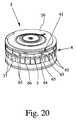
図1は、本発明の小出し器具1を―縮尺通りではない例示目的で―概略断面図で示している。小出し器具1は、好ましくは、能動型器具、特にガス駆動式のものである。好ましくは、小出し器具1は、好ましくは、ユーザ、特に患者(図示せず)のための口又は鼻吸入器、特に乾燥粉末吸入器である。 FIG. 1 shows a
好ましくは、小出し器具1は、携帯可能であると共に(或いは)手持ち形である。 Preferably, the
小出し器具1は、本明細書の導入部分で定義された調合薬2を小出しするために使用されるのが良い。特に、吸入のための医薬調合物2又は調合薬2が用いられる。調合薬2は、好ましくは、少なくとも1種類の薬剤を含み又は少なくとも1種類の薬剤から成る。調合薬2を小出しすると、図1に示されているようにスプレー3が生じる。スプレー3は、微粒子(固体及び(又は)液体)を含み又は微粒子から成り、好ましくは、所望のスプレープルーム特性を有する。 The
調合薬2は、液体、特に溶液、懸濁液又はこれらの任意の混合物、即ち、所謂サスリューションであるのが良い。好ましくは、互いに異なる薬剤を同時に小出しする場合、サスリューションを用いるのが良い。サスリューションの原理は、互いに異なる薬剤を溶液及び懸濁液として同時に一調合薬の状態に組み合わせることができるということに基づいている。この点に関しては、欧州特許出願公開第1087750(A1)号明細書を参照されたい。なお、この特許文献を参照により引用し、この点に関するその記載内容を追加の開示内容として本明細書に組み込む。 The
好ましくは、調合薬2は、粉末である。粉末は、純粋な薬剤又は少なくとも2種類の薬剤の混合物若しくは少なくとも1種類の薬剤の任意他の混合物であって良い。加うるに、粉末は、少なくとも1種類の他の物質、特に薬剤キャリヤ、例えばラクトースを含むのが良い。以下において、説明は、調合薬2としての粉末に焦点を合わせる。しかしながら、これは、液体調合薬2が用いられる場合に同様に当てはまる。 Preferably,
好ましくは、粉末粒子の(解凝集状態の)平均直径は、約2〜7マイクロメートル、特に6マイクロメートル以下である。これは、特に、粉末が薬剤キャリヤ、例えばラクトースを含んでいない場合に当てはまる。 Preferably, the average diameter (in the deagglomerated state) of the powder particles is about 2-7 micrometers, in particular 6 micrometers or less. This is especially true when the powder does not contain a drug carrier such as lactose.
粉末が薬剤キャリヤ、例えばラクトース及び少なくとも1種類の薬剤を含んでいる場合、粉末2の粒径は、20〜300マイクロメートル、特に約30〜60マイクロメートルである場合がある。しかしながら、後で詳細に説明する解凝集の結果として、この場合、これよりも小さな粒径、例えば約10マイクロメートル以下のスプレー3が生じる場合がある。特に、薬剤は、解凝集中、薬剤キャリヤから分離される場合があり、その結果、主として、薬剤は、約2〜6μmのその小さな粒径により吸入され、これよりも大きな薬剤キャリヤは、小出し器具を吸入器として用いた場合、飲み込まれることになる。代替的に又は追加的に、薬剤キャリヤを壊すこと又は開くことは、解凝集中に可能である。 If the powder comprises a drug carrier, such as lactose and at least one drug, the particle size of
上述すると共に後述する直径は、全体として中間の空力学的直径として理解されるのが良く且つ(或いは)スプレー3の粒子の粒径又はフラクション(主要な又は平均の粒径又はフラクション)に当てはまる場合がある。 The diameters described above and below are generally understood as intermediate aerodynamic diameters and / or apply to the particle size or fraction (primary or average particle size or fraction) of the
好ましくは、調合薬2は、別々の又は個々の投与分の状態に予備計量されており、これら投与分は、特に吸入のために小出し器具1により次々に放出できる。 Preferably, the
小出し器具1は、調合薬2の好ましくは多数回の且つ予備計量された投与分を貯蔵する貯蔵器具4を受け入れ又はこれを有するようになっている。貯蔵器具4は、小出し器具1内に組み込まれるのが良く又は小出し器具1の一部を形成するのが良い。変形例として、貯蔵器具4は、小出し器具1に挿入でき又はこれに連結でき、オプションとして交換できる別個の部品であっても良い。 The
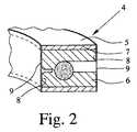
図2は、好ましくはリング状の貯蔵器具4の概略断面を示している。 FIG. 2 shows a schematic cross section of a
貯蔵器具4は、好ましくは、キャリヤ5と、少なくとも1つのインサート6、好ましくは多数個のインサート6とを有している。特に、キャリヤ5は、20個〜100個、好ましくは30個〜60個又は65個のインサート6を有し又は支持するのが良い。各インサート6は、好ましくは、調合薬2の予備計量された1回投与分を収容する。しかしながら、各インサート6は又、2種類以上の調合薬2、即ち互いに異なる調合薬2を収容しても良い。追加的に又は代替的に、互いに異なるインサート6は、互いに異なる調合薬を収容しても良い。本発明では、「異なる」という用語は、特に、調合薬2が調合薬2、例えば液体又は乾燥粉末の組成、薬剤、投与分又は量、濃度及び稠度のうちの少なくとも1つにおいて異なっていることを意味している。また、特に2つ又は3つ以上のインサート6から2又は3回以上の投与分又は互いに異なる調合薬を同時に放出することも可能である。 The
貯蔵器具4又はキャリヤ5は、好ましくは、インサート6を受け入れ又はインサート6を備えた多数のキャビティ7又は入れ物を有する。特に、各インサート6は、別個のキャビティ7内に配置されている。好ましくは、キャビティ7は、互いに別々であり、特に、互いに対して密封されている。 The
この実施形態では、各キャビティ7は、少なくとも1つの開口部8、特に2つの好ましくは反対側に位置する開口部8(この場合、半径方向内側及び外側周囲又は周辺のところに位置する)を有する。 In this embodiment, each
キャビティ7又はその開口部8は、それぞれのカバー又は密封材9で覆われており、これらカバー又は密封材は、好ましくは、それぞれのキャビティ7又はキャリヤ5の互いに反対側に設けられた好ましくはヒートシールされた箔によって形成される。この実施形態では、密封材9は、特に、金属製の箔、例えばアルミニウム箔、プラスチック箔、多層構造体等である。密封材9は、好ましくは、インサート6及び(又は)調合薬2を湿度、汚れ、水分及び(又は)その他から保護する。密封材9は、それぞれ、耐性があると共に(或いは)不透性であり、特にガス密である。 The
この好ましい実施形態では、貯蔵器具4又はキャリヤ5は、リング状であり、インサート及び(又は)キャビティ7は、少なくとも実質的に半径方向に延びている。インサート及び(又は)キャビティ7は、貯蔵器具4又はキャリヤ5の周囲に沿ってぐるりと又は貯蔵器具4又はキャリヤ5に沿って、好ましくは等間隔を置いた状態で分布して設けられている。 In this preferred embodiment, the
この実施形態では、貯蔵器具4/キャリヤ5は、好ましくは、図1に示されている軸線“A”回りに回転可能である。特に、小出し器具1を開くことができ、貯蔵器具4/キャリヤ5を挿入し又は元に戻すことができる。 In this embodiment, the
キャリヤ5は、成形要素、リング、ストライプ、カートリッジ、ブリスタ又は容器であるのが良い。好ましくは、貯蔵器具4又はキャリヤ5は、剛性であり又は少なくとも本質的に硬い。 The
好ましくは、キャリヤ5は、箔、プラスチック、セラミック及び(又は)複合材料、特に熱可塑性樹脂又は熱可塑性エラストマーで作られる。 Preferably, the
好ましくは、各キャビティ7又は入れ物は、好ましくは、特に関連のインサート6のガイドを形成し、インサート6は、キャビティ7又は入れ物から少なくとも一方向に又は一方向にのみ動くことができ且つ(或いは)キャビティ7又は入れ物から少なくとも部分的に又は部分的にのみ出ることができる。 Preferably, each
図1は、右側のインサート6がその関連のキャビティ7及び(又は)外側開口部8から既に部分的に押し出されると共に(或いは)密封材9を開放するためにその関連のキャビティ7のそれぞれの密封材9に既に押し通された状況を示している。図1の左側に示されたインサート6は、依然として、その閉鎖されると共に密封されたキャビティ7内に位置している。 FIG. 1 shows that the
各インサート6は、好ましくは、調合薬2のそれぞれの投与分が詰め込まれた状態で貯蔵器具4又はキャリヤ5から別個に作られ、次にそのそれぞれのキャビティ7又は入れ物内に挿入される。 Each
好ましくは、各インサート6は、成形されると共に(或いは)箔、プラスチック、セラミック及び(又は)複合材料、特に熱可塑性樹脂又は熱可塑性エラストマーで作られ、密封材は、エラストマー又はシリコーンで作られる。 Preferably, each
好ましい実施形態によれば、キャリヤ5及び(又は)インサート6は、以下の物質、即ち、ABS(アクリルニトリル‐ブタジエン‐スチレンコポリマー)、SAN(スチレン‐アクリルニトリルコポリマー)、PBT(ポリブチレンテレフタレート)、PC(ポリカーボネート)、CA(セルロース系アセテート)、EVA(エチレンビニルアセテートコポリマー)、PA(ポリアミド)、PE(ポリエチレン)、PP(ポリプロピレン)、PMMA(ポリメチルメタクリレート)、POM(ポリオキシメチレンポリアセタール)、PPS(ポリフェニレンスルフィド)、PS(ポリスチレン)、PBTP(ポリブチレンテレフタレート)、TPU(熱可塑性ポリウレタン)、PCとPBTPの配合物、PCとABSの配合物、LCP(液晶ポリマー)、PHCS(ポリピロール又はポリチオペン)、PPA(ポリフタルアミド)、PSU(ポリスルフォン)、PTFE(ポリテトラフルオルエチレン)、PUR(ポリウレタン)、SB(スチレン‐ブタジエンコポリマー)、PIB(ポリイソブチレン)、PAN(ペルオキシアクリルニトレート)、PET(ポリエチレンテレフタレート)、AMMA(アクリロニトリル‐メチルメタクリレートコポリマー)、PAR(ポリアリールエート)、PEEK(ポリエーテルエーテルケトン)、COC(シクロオレフィンコポリマー)のうちの少なくとも1つ又はこれらの任意の混合物又は配合物で作られている。 According to a preferred embodiment, the
各インサート6は、好ましくはブロック状のユニットを形成すると共に(或いは)剛性であるのが良い。変形例として、インサート6は、可撓性であっても良い。特に、各インサート6は、一体形ユニットであっても良く、多数の要素から成っていても良い。特に、インサート6は、一コンポーネントを形成し又は一体品で作られる。各インサート6は、成形要素であっても良く、カートリッジであっても良く、ブリスタであっても良く、カプセルであっても良く容器等であっても良い。 Each
以下において、1つのインサート6の好ましい構成について説明する。好ましくは、インサート6は全て同一である。しかしながら、インサート6(全て又は幾つか)は、互いに異なっていることも可能である。例えば、2つ又は3つ以上の群をなす互いに異なるインサート6を設けても良い。一方の群は、他方の群とは異なる投与分又は異なる調合薬2を有することが可能である。例えば、互いに異なる群のインサート6は、互いに交互に配置されても良く、その結果、患者又はユーザは、例えば、毎朝、一方の群のインサート6を用い、毎晩他方の群のインサート6を用いることができるようになる。 Below, the preferable structure of the one
各インサート6は、好ましくは、1回投与分の調合薬2の貯蔵チャンバ10を有する。図2及び図3の概略断面図並びに図3のIV‐IV線に沿って取った図4の概略断面図は、インサート6の好ましい一実施形態を示している。インサート6は、調合薬2のための貯蔵チャンバ10を有している。この実施形態では、貯蔵チャンバ10は、好ましくは、インサート6の成形ベース部材11中に形成される。 Each
インサート6/ベース部材11は、小出し操作中、調合薬2を解凝集すると共に(或いは)放出するダクト12等を更に有している。調合薬2は、小出し操作中、特に粉末を解凝集すると共に(或いは)スプレー3を形成するためにダクト12を通って小出しされる。 The
好ましくは、ダクト12は、断面が平べったく且つ(或いは)長方形である。特に、この断面は、1mm未満の水力直径に相当している。特に、ダクト12は、国際公開第2006/037636(A2)号パンフレットで説明されているように設計されており、この国際公開を参照により引用し、その開示内容を本明細書の一部とする。 Preferably, the
別の(図示していない)実施形態によれば、ダクト12は、調合薬2のためのリザーバ(貯蔵チャンバ10)としても使用できる。この場合、別個の貯蔵チャンバ10は不要である。この場合、ダクト12は、ガスと調合薬2の十分な混合を可能にすると共に粉末調合薬2の十分な解凝集を可能にするよう設計されている。 According to another (not shown) embodiment, the
好ましくは、所望のスプレー特性を備えたスプレー3は、インサート6/ダクト12から直接噴出され又は放出される。 Preferably, the
特に、インサート6は、一コンポーネントを形成し又は一体品で作られている。 In particular, the
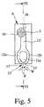
インサート6又はダクト12は、出口15又はダクト12の端のところに設けられ又は図5の別の実施形態の概略縦断面図に示されているようにダクト12によって形成されたノズル構造13を有するのが良い。 The
好ましくは、貯蔵チャンバ10及び(又は)ダクト12/ノズル13は、ベース部材11により又はベース部材11中に、特にベース部材11に設けられた凹部、溝等及び図4に示されているような関連のカバー部材14により形成されている。特に、ダクト12は、貯蔵チャンバ10からインサート6の出口15まで延び、特に、図1に示されているように調合薬2をスプレー3として直接放出し又は小出しするチャネルを形成している。好ましくは、ベース部材11は、成形されると共に(或いは)剛性である。好ましくは、カバー部材14は、剛性であると共に(或いは)ベース部材11に溶接されると共に(或いは)、密封されると共に(或いは)、接着される。 Preferably, the
注目しなければならないこととして、インサート6は、特にその出口15のところのみ、開いているのが良く又は好ましくは開いており、即ち、密封されていない。実験結果の示すところによれば、キャリヤ5/それぞれのキャビティ7の密封具合は、十分である。ダクト12/ノズル構造13は、好ましくは、断面が非常に小さく又は破断要素又は任意他の適当な手段を備えており、調合薬2は、好ましくは密封材9が開かれた場合でも且つ(或いは)小出し器具1/貯蔵器具4の激しい揺さぶり中であっても放出されず、ガス(空気)がインサート6及びダクト12中に送り込まれた場合にのみ放出されるようになっている。 It should be noted that the
貯蔵器具4は、1回投与分のための1つの貯蔵チャンバ10又は互いに異なる調合薬2の入った多数の貯蔵チャンバ10を備えたインサート6を1つだけ有するのが良い。好ましい実施形態では、各インサート6及びダクト及び(又は)ノズル構造13は、1回投与分及び(又は)1回使用向きであるに過ぎないが、貯蔵器具4は、好ましくは、多数のインサート6を有し、かくして、特に次々に小出しできる多数回投与分の調合薬2を収容している。 The
さらに、インサート6及びキャビティ7は、好ましくは、密封材9がインサート6の端面に接触し、かくして出口15を覆うように互いに構成されている。これにより、調合薬2が所望の小出し前にダクト12/出口15を通って散るのを阻止する(一段と阻止する)ことができる。密封材9による密封又は覆い効果を増大させるため、インサート6は、キャビティ7よりも僅かに長く且つ(或いは)その出口側が突き出ているのが良く且つ(或いは)その出口15が密封材9に押し付けられるのが良く、或いはこの逆の関係が成り立つのが良い。 Furthermore, the
好ましくは、ノズル構造13は、図5の実施形態に示されているように速度を減速する手段を形成する。この手段は、この場合、多数のジェットを互いに衝突させる手段を形成する。この手段は、多数の、即ち2つのジェットPを形成し、これらジェットは、図5に示されているように互いに当たり又はぶつかる。この実施形態では、ダクト12は、2つの区分12a,12bに分かれ、これら区分は、開口部又は出口15が互いに傾斜していて区分12a,12bから噴出したジェットPが互いに傾けられて互いに当たるよう設計されている。例えば、分流器11a又は任意他の案内手段を流路中に配置して図5に示されているようなダクト12の少なくとも2つの区分及び(又は)最後の部分12a,12bを形成しても良い。 Preferably, the
図5の実施形態は、3つ以上のジェットPを互いに衝突させるのにも適している。例えば、結果的に4つの出口方向が得られると共にジェットPが円錐の表面上に位置するような上述したのと同様な構造を図面の平面に垂直な断面平面に設けることが可能である。しかしながら、同様な効果を持つ多数の他の構造が可能である。 The embodiment of FIG. 5 is also suitable for causing three or more jets P to collide with each other. For example, it is possible to provide a structure similar to that described above in a cross-sectional plane perpendicular to the plane of the drawing, with the result that four exit directions are obtained and the jet P is located on the surface of the cone. However, many other structures with similar effects are possible.
ジェットP相互間の衝突角度Wは、粉末については30°〜180°、好ましくは少なくとも90°、特に約90°〜150°である。 The impingement angle W between the jets P is 30 ° to 180 °, preferably at least 90 °, in particular about 90 ° to 150 ° for the powder.
ジェットPの衝突の結果として、スプレー3の速度の減少が得られると共に(或いは)粉末の解凝集又は小滴の形成が得られると共に(或いは)キャリヤからの薬剤粒子の分離が得られると共に(或いは)スプレー3の良好な集束が得られる。これら効果は、衝突角度Wで決まる。衝突角度Wが大きいと、結果的に良好な作用効果が得られる傾向がある。液体ジェットとは対照的に、90°以上の衝突角度Wが可能であり、粉末に好ましい。 As a result of the impingement of the jet P, a reduction in the speed of the
変形例として、このノズル構造13又は任意他の適当なノズル構造をダクト12に代えて又はダクト12との任意他の組み合わせ状態で用いても良い。 As a variant, this
図6は、図5のVI‐VIに沿って取ったインサート6の概略断面図であり、インサート6は、そのキャビティ7内に/貯蔵器具4内に収容されているが、既に1つの開口部8から幾分外方に動いている。 FIG. 6 is a schematic cross-sectional view of the
インサート6は、好ましくは、好ましくは加圧されたガスを貯蔵チャンバ10内に供給して調合薬2をダクト12/ノズル構造13中に押し進めて上述のスプレー3を直接生じさせるための入口を有する。この実施形態では、入口は、好ましくは、弱い又は薄くなった部分により形成されると共に(或いは)ベース部材11中に形成された好ましくは管状の凹部16又は止まり穴として設計されている。好ましくは、凹部16は、貯蔵チャンバ10に直接結合されておらず、シール又は中間若しくは薄くなった壁等によって分離されている。この壁は、特にそれぞれのインサート6が以下において説明するようにガス供給源に連結されたとき、例えば連結要素、例えば穿通要素17、例えば図6に概略的に示されているような針により又は任意他の適当な開放手段、連結手段及び(又は)供給手段によって突き破られる。好ましくは、穿通要素17は、中実又は閉鎖された先端部17a及び先端部17aに隣接して設けられていて、加圧ガス/空気をインサート6/貯蔵チャンバ10中に供給する側開口部17bを備えた中空針である。 The
本発明では、「穿通要素17」という表現は、好ましくは、貯蔵器具4、キャリヤ5、キャビティ7及び(又は)インサート6を開くと共に(或いは)結合すると共に(或いは)ガスをインサート6又はその貯蔵チャンバ10に直接又は間接的に供給する他の全ての適当な形式の手段を含む。 In the context of the present invention, the expression “penetrating
注目されなければならないこととして、インサート6及びキャビティ7の断面は、好ましくは、多角形、特に長方形であり、或いは、インサート6がキャビティ7内で回動することを阻止するために好ましくは他の案内手段が設けられる。しかしながら、インサート6が凹部16又はガス供給のための任意他の連結部/入口に関し且つその出口15に関して回転対称である場合、インサート6は、円筒形であっても良く且つ(或いは)キャビティ7内で回転可能であっても良い。これにより、製造の際におけるキャビティ7内へのインサート6の挿入を容易にすることができる。 It should be noted that the cross section of the
ダクト12は、好ましくは、図3及び図5に示されているように少なくとも貯蔵チャンバ10に接線方向に連結される。好ましくは、ダクト12は、好ましくは円筒形のチャンバ10の一方の軸方向端部のところに連結され、ガス入口(凹部16/穿通要素17)は、図6に示されているようにチャンバ10の他方の軸方向端部に連結され又は連結可能である。特に、ガス入口も又、貯蔵チャンバ10に接線方向に連結されており、従って、ダクト12を通るガスと調合薬2の混合物の放出を支援するスワール方向でガスに入ったときにスワールが生じるようになり、ダクト12は、スワールの回転方向に対して接線方向に連結されている。 The
小出し器具1は、好ましくは、加圧ガス、特に空気を用いて調合薬2をダクト12/ノズル構造13中に送り込んで粉末を解凝集すると共に(或いは)粉末微粒子を含むスプレー3を生じさせる。好ましくは、小出し器具1は、図1に示されているように加圧ガスをもたらす手段、この実施形態では空気ポンプ18を有し、この空気ポンプは、好ましくは、例えば取っ手又はアクチュエータ19及び(又は)別の実施形態では後で示されるばね手段によって示されるように手動で作動され又は稼働されるのが良い。特に、空気ポンプ18は、ベローから成り又はベローによって形成される。しかしながら、空気ポンプは、ピストン・シリンダ装置であっても良い。空気ポンプ18に代えて、加圧ガスをもたらす手段は、例えば小出し器具1に動力供給する加圧又は液化ガスを収容し、即ち、所望に応じて調合薬2を小出しするカプセル、容器等であっても良い。したがって、「ガスを加圧する手段」という表現は、好ましくは、ポンプ18のこれらの変形例及び類似した変形例を含むよう広義に理解されなければならない。 The
加圧ガスをもたらす手段/空気ポンプ18は、300kPa未満、特に約50〜200kPaのガス圧力をもたらすことができる。これは、好ましくは、小出し器具1を作動させるのに十分である。液化ガス又は加圧ガス入り容器を用いる場合、ガス圧力は、100kPa〜約700kPaの場合がある。この場合、圧力を好ましい圧力範囲に減少させ又は絞り、その後ガスを貯蔵器具4、特にそれぞれのインサート6の貯蔵チャンバ10に供給する。 The means for providing pressurized gas /
好ましくは、本明細書において記載した圧力値の全ては、ゲージ圧力、即ち、差圧である。全ての圧力値は、ガス貯蔵手段、例えば加圧又は液化ガス入りの容器内の圧力又は空気ポンプ18により提供される圧力に関し又はチャンバ10及び(又は)ダクト12内で作用する圧力に関する。 Preferably, all of the pressure values described herein are gauge pressures, i.e. differential pressures. All pressure values relate to the pressure in a gas storage means, for example a pressurized or liquefied gas container or the pressure provided by the
図1は、小出し器具1が、好ましくは、キャビティ7を個々に開き、インサート6を好ましくは半径方向に(この場合、外方に)及び(又は)関連の開口部8及び(又は)密封材9を通って個々に動かすと共に(或いは)インサート6をガス供給手段、特に空気ポンプ18に個々に連結する機構体を有する。この機構体20は、好ましくは、穿通要素17及び(又は)任意他の適当な連結又は作動要素を有する。 FIG. 1 shows that the
特に、第1の作動段階では、穿通要素17は、この場合、密封材9を突き破り、次に、凹部16内に挿入され、そして中間端部又は弱められた壁を通って貯蔵チャンバ10内に挿入され、かくして、この穿通要素は、それぞれのインサート6をガス供給源に連結する。次の運動前、次の運動と同時に又は次の運動後に、例えば、次の運動中、機構体20は、インサート6を他方の又は外側の開口部8を通り、そしてそれぞれの密封材9を通って押し込んで少なくとも部分的にそのキャビティ7から押し出る。好ましくは、機構体20は、それぞれのインサート6に直接作用してその運動を生じさせる。この場合、穿通要素17は、好ましくは、機構体20/穿通要素17を動かしたときにインサート6の所望の運動を確実に生じさせるようインサート6に当接する肩、当接部又はスリーブ21(図6に概略的に示されている)を備える。最終の状況は、図1の右側に且つ図6にインサート6が突き出た状態で示されている。 In particular, in the first operating phase, the penetrating
注目しなければならないこととして、任意他の駆動機構体を用いても、インサート6を動かして一方の開口部8一方の密封材9それぞれの出口15又はインサート6それ自体を開くことができる。特に、インサート6の連結又は穿通とは独立して密封材9中へのインサート6の好ましい押し込みを実現することが可能である。 It should be noted that even if any other drive mechanism is used, the
インサート6は、それぞれの密封材9の開放を容易にするため、好ましくは、開放手段、特に先端部分11bを有すると共に(或いは)その出口端部がテーパしている。特に、インサート6又はそのベース11は、好ましくはインサート6又はベース11の少なくとも一方の平坦な側部に又はこの平坦な側部にのみ設けられた傾斜部分11cを有し、インサート6/ベース11は、図4及び図6に概略的に示されているように出口15に向かってテーパするようになっている。かくして、表面積が減少し又は最小限に抑えられた前面を形成する先端部又は先端部分を形成することが可能である。出口端部のところに切れ刃を形成することさえも可能である。 In order to facilitate the opening of the
代替的に又は追加的に、任意他の適当な切断要素をインサート6のところ、特にその出口端部のところに開放手段として形成し又は設けることが可能である。 Alternatively or additionally, any other suitable cutting element can be formed or provided as an opening means at the
特に、インサート6の行程又は外側運動は、密封材9の所望の開放が保証され、特に、開放された密封材9の破断、切断及び(又は)破断部分がインサート6の出口15を塞ぎ、覆い又は邪魔をすることができないよう構成され、好ましくは長い。この実施形態では、密封材9は、インサート6の先端部分11bが配置されている開口部8の一方の側のところが実質的に破断する。開口部8のこの側に取り付けられた密封材9の短い残部は、突出したインサート6の出口を邪魔することができない。というのは、この残部は、好ましくは、インサート6の外方行程よりも短いからである。開口部8の他方の側に連結された密封材9の長い方の部分は、インサート6により曲げられ又は回って遠ざけられる。 In particular, the stroke or outward movement of the
この実施形態では、密封材9の開放及び(又は)切断は、それぞれのインサート6が作動及び後に行われる小出しのためにそのキャビティ7から外方に動かされると、好ましくは長方形の開口部8の一方の側のところ又は一方の縁部に隣接したところで起こる。開放手段、先端部分11b、切断要素等は、インサート6の一方の側に、特に、そのキャビティ7及び開口部8の一方の側のところに配置され、その結果、それぞれの密封材9の上述の開放がインサート6を外方に動かしたときに上述したように起こるようになる。換言すると、開放又は切断手段の配設場所は、特に開口部8の一方の側部及び(又は)一方の縁部に隣接したところでそれぞれの密封材の所望の開放パターン及び(又は)位置決めを保証し又は生じさせるようになっているのが良く、特にそのように用いられる。しかしながら、他の開放場所を選択することができる。例えば、それぞれの密封材9の中央を開放することも可能である。追加的に又は代替的に、インサート6は、それぞれの密封材9を多数の場所で次々に又は同時に開放し、破断し又は切断するよう構成されても良く、具体的には、2つ又は3つ以上の開放又は切断手段を設けることによってこれを行う。 In this embodiment, the opening and / or cutting of the
この実施形態では、インサート6は、好ましくは半径方向且つ(或いは)外方に且つ(或いは)空気ポンプ18から遠ざかって且つ(或いは)その長手方向に且つ(或いは)主放出方向に且つ(或いは)マウスピース24の主延長方向に動くことができる。しかしながら、他の運動も又可能である。この場合、並進運動のみが行われる。しかしながら、追加的に又は代替的に若しくは重ね合わせ状態で回転又は回動運動を行っても良い。 In this embodiment, the
好ましくは、貯蔵器具4、キャリヤ5及び(又は)キャビティ7は、インサート6の可能な運動又は最大運動を制限する手段を有する。好ましくは、この手段は、圧力嵌めによりインサート6を停止させる。この実施形態では、この手段は、それぞれのインサート6のそれぞれの当接部、例えば肩23と相互作用する停止部22、例えば肩、突起等から成り、従って、インサート6は、肩23がそれぞれの停止部22に当接し、かくしてインサート6のそれ以上の外方運動を阻止した場合、図6に概略的に示されているようにそれぞれのキャビティ7から出るその運動が制限されるようになっている。しかしながら、注目されなければならないこととして、同一の効果を有する任意他の技術的解決手段も又利用できる。 Preferably, the
小出しのため、ガスを圧力下で穿通要素17又は任意他の適当な供給要素を介して貯蔵チャンバ10に供給する。 For dispensing, gas is supplied to the
ガス(空気)は、貯蔵チャンバ10内にそれぞれの流れを生じさせてガスと粉末を混合すると共に1回投与分をダクト12中に送り込む。 The gas (air) causes the respective flow in the
粉末は、比較的低いガス圧力(好ましくは、300kPa未満、特に約50〜200kPa)で放出され、特に、ダクト12中に送り込まれる。先行技術の小出し器具内のガス圧力よりも著しく低いこの低いガス圧力により、比較的低い放出速度及びかくして遅い伝搬速度の遅いスプレー3の実現が可能になる。 The powder is released at a relatively low gas pressure (preferably less than 300 kPa, in particular about 50-200 kPa), and in particular is fed into the
好ましくは、貯蔵チャンバ10は、ガスと粉末を混合する混合チャンバを形成する。チャンバ10は、好ましくは、ガスが粉末とガスを良好に混合させるスワール又は渦流を生じさせるよう設計されている。好ましくは、チャンバ10は、断面が実質的に円形であり、特に円筒形である。しかしながら、他の形状も又可能である。 Preferably, the
さらに、チャンバ10は、尖った縁部、コーナ部等を備えておらず、ガスが全てのチャンバ表面を掃過して粉末がこの表面上に堆積するのを阻止し、粉末の完全な放出を保証し又は可能にするよう滑らかな輪郭を有している。特に、穿通要素17又は任意他の供給要素により形成されるガス入口は、軸方向又は出口方向に関し出口、即ちダクト12及び(又は)ノズル13と反対側に配置されている。 Furthermore, the
小出し操作中、スプレー3は、好ましくは、それぞれのインサート6又はそのダクト12/ノズル構造13によって直接に生じ又はそれぞれのインサート6又はそのダクト12/ノズル構造13によってのみ生じ、そして図1に示されているように小出し器具1のマウスピース24中に送り込まれて患者又はユーザ(図示せず)によって吸入される。 During the dispensing operation, the
1回投与分を小出しした後又は次の投与分を小出しする前に又は次の投与分を小出しするために、穿通要素17は、連結状態のインサート6から引っ込められる。好ましくは、それぞれのインサート6も又、そのキャビティ7内に引っ込められ、又は押し戻される。 The penetrating
次に、キャリヤ5を更に1ステップ割送りし又は次のインサート6まで割送りし、特に、割送り又は運搬機構体(図示せず)によって回転させる。この機構体は、好ましくは、上述したように、アクチュエータ19又は任意他のアクチュエータを作動させることにより、小出し器具1のキャップ又はカバーを開くことによるなどして作動される。 The
注目されなければならないこととして、本発明、特に小出し器具1及び(又は)貯蔵器具4は、1種類の薬剤、薬剤の配合物又は少なくとも2種類又は3種類の別々の薬剤を小出しするために使用できる。後者の場合、別々の薬剤は、別々の貯蔵チャンバ10内に貯蔵され、小出し操作中、薬剤は、共通混合チャンバ又はこれらのそれぞれの貯蔵チャンバ10内でガスと混ぜ合わされる。さらに、共通ダクト12若しくはノズル構造13を通って又は別々のダクト12、ノズル構造13若しくはインサート6を通って別々の薬剤を放出することができる。後者の場合、別々の薬剤は、別々のダクト12/ノズル13を出た後又はマウスピース24若しくは任意他の適当な(追加の)混合チャンバ内で混ぜ合わされる。また、別々の薬剤のジェットを衝突させることにより別々の薬剤を混合することも可能である。別々の薬剤を小出しするため、共通ガス供給源又はガスを加圧する手段、例えば空気ポンプ18を用いることが好ましい。 It should be noted that the present invention, in particular the dispensing
好ましくは、スプレー3は、2m/秒未満、特に1m/秒未満の平均速度(出口15又はマウスピース24から20cmの距離を置いたところで測定される)を有する。好ましくは、スプレー3の平均持続時間は、少なくとも0.2又は0.3秒、特に約0.5〜25秒である。 Preferably, the
図1の好ましい実施形態では、キャビティ7は、貯蔵器具4又はキャリヤ5の接線方向又は半径方向に差し向けられている。その結果、インサート6を接線方向又は半径方向に、特に外方に個々に動かすことができ、その目的は、図1に示されているように調合薬2のそれぞれの1回投与分を小出しするためにそれぞれの外側密封材9を開放することにある。したがって、機構体20は、好ましくは、インサート6を個々にガス供給源に連結し、インサート6を個々にそれぞれのキャビティ7から少なくとも部分的に押し出すと共に(或いは)それぞれの密封材9中に押し込むために半径方向に動作する。この半径方向運動により、特に軸方向における小出し器具1の非常にコンパクトな設計が可能である。 In the preferred embodiment of FIG. 1, the
好ましくは、マウスピース24及び小出し方向は、図1に示されているように半径方向又は接線方向に延びる。 Preferably, the
好ましくは、小出し器具1は、好ましくは手動による作動のためのレバー若しくは取っ手(図示せず)、アクチュエータ19、又は任意他の駆動若しくは作動手段を有し、その目的は、キャリヤ5を更に1ステップ、即ち、次のインサート6まで割送りすると共に(或いは)機構体20を作動させて好ましくはそれぞれのインサート6をガス供給源に連結すると共に(或いは)それぞれのインサート6を動かし又は押すと共に(或いは)それぞれの密封材9を開いて調合薬2のそれぞれの投与分を小出しすることにある。 Preferably, the
小出し器具1は、好ましくは機械的にのみ動作することは注目されなければならない。 It should be noted that the
注目されなければならないこととして、小出し器具1は、回転可能なアクチュエータ19及び(又は)マウスピース24の可動カバー25によっても作動可能である。特に、アクチュエータ19は、マウスピース24のカバー25を形成することができる。この実施形態では、アクチュエータ19は、好ましくは、半径方向に且つ(或いは)マウスピース24のカバー25とは独立して動くことができる。 It should be noted that the
別の実施形態(図示せず)によれば、インサート6は、ダクト12、ノズル13等の設けられていないカプセル等として形成されても良い。これとは異なり、各インサート6は、調合薬2のそれぞれの投与分を小出しするために個々にガス供給源及び共通の出口構造、例えばダクト12、ノズル13等に連結される。 According to another embodiment (not shown), the
別の実施形態によれば、補助包装材を特に貯蔵目的で、貯蔵器具4/キャリヤ5を小出し器具1内に挿入する前に、貯蔵器具4/キャリヤ5を包装してこれを保護するために用いられる場合がある。加うるに、貯蔵器具4/キャリヤ5を含む器具1全体を水蒸気を通さない補助包装材内に貯蔵するのが良い。 According to another embodiment, for the purpose of wrapping and protecting the
別の実施形態によれば、小出し器具1は、呼吸作動式であっても良く、特に、調合薬2は、好ましくは感圧手段、例えば破断要素、メンブレン、弁又は任意他の機構体の使用により、患者又はユーザの吸入速度が所定のレベルに達した後でしか放出されることはない。 According to another embodiment, the
別の実施形態によれば、小出し器具1は、受動型吸入器であっても良く、この場合、患者又はユーザ(図示せず)は、吸息の際に空気流をそれぞれの開かれたインサート6中に吹き込んでこの空気流が調合薬2を同伴し、患者/ユーザによる吸入のためにマウスピース24内に所望のスプレー3を形成するようになっている。 According to another embodiment, the
注目されなければならないこととして、「小出し器具」という用語は、好ましくは、他の放出器具、ディスペンサ等を含むものとして広義に理解されなければならず、好ましくは、調合薬2又は任意他の流体は、必要な場合にのみ特に非連続的にスプレーされ又は噴霧化される。 It should be noted that the term “dispensing device” is preferably to be broadly understood as including other release devices, dispensers, etc., preferably preferably in
以下において、別の図面を参照して小出し器具1の別の好ましい実施形態について説明する。以下の説明は、この別の実施形態と先の実施形態の関連の差に焦点を当てる。特に、先の説明及び記載は、たとえ繰り返されていなくても、適宜且つ(或いは)追加的に当てはまる。 In the following, another preferred embodiment of the
図7は、小出し器具1の別の実施形態を斜視図で示している。小出し器具1は、マウスピース24を覆うカバー25を有している。好ましくは、カバー25は、図示のようにマウスピース24を開き又はマウスピース24のカバーを取るよう回動可能である。好ましくは、マウスピース24は、小出し器具1のハウジング26にスナップ装着されている。 FIG. 7 shows another embodiment of the
小出し器具1は、そのハウジング26の一方の側に、好ましくは、マウスピース24の反対側に且つ(或いは)小出し器具1の主スプレー方向(好ましくは半径方向)と反対側に設けられたアクチュエータ19を有している。アクチュエータ19は、好ましくは、握り又は取っ手を形成している。したがって、「握り」という用語が以下において用いられる。 The
握り19は、好ましくは、小出し器具1を後で詳細に説明するように作動させるために半径方向に動くことができる。特に、握り19を図7に示す初期位置から半径方向外方に引っ張ったりその初期位置に押し戻したりすることができる。これら操作は、以下において「引く」及び「押す」と呼ばれる場合がある。しかしながら、これら作動的運動は、任意他の方向又は形式の運動、例えば非並進運動によっても実現できることは注目されなければならない。 The
先ず最初に、図8〜図10を参照して小出し器具1の基本原理について説明する。図8〜図10は、原理を説明するために小出し器具1の内部コンポーネントの極めて基本的な略図(縮尺通りではない)を示しているに過ぎない。特に、ハウジング26及び握り19は省かれている。さらに、貯蔵器具4は、概略的な仕方でしか示されておらず、特に、図9及び図10では不完全に又は部分的にのみ示されている。特に、多くの細部、例えば密封材9、出口15等は省かれている。貯蔵器具4の好ましい構成については、この小出し器具1の機能的な基本原理を説明した後に後述する。 First, the basic principle of the
小出し器具1は、能動型アトマイザ又は吸入器である。ガスを加圧する手段は、好ましくは、空気ポンプ18としても構成されている。この場合、空気ポンプ18は、圧送要素としてベロー27を有している。しかしながら、任意他の適当な圧送要素を用いることができる。 The
小出し器具1/空気ポンプ18は、圧送要素、即ちベロー27を作動させるためのエネルギー貯蔵手段又はばね力貯蔵手段、特にばね28を更に有している。 The
空気ポンプ18(ベロー27及びばね28)は、好ましくは、特に摺動方式で又はそりのように半径方向に動くことができる。好ましくは、空気ポンプ18は、スライダ29を形成し又はこれによって支持される。 The air pump 18 (bellows 27 and spring 28) is preferably able to move in a radial direction, in particular in a sliding manner or like a sled. Preferably, the
特に、空気ポンプ18及びスライダ29を以下において「空気組立体」と称する。 In particular, the
好ましくは、空気組立体は、先の実施形態に関して上述した機構体20を形成し又はこれを含む。この目的のため、空気組立体は好ましくは、穿通要素/針17を保持する針ホルダ30を有する。穿通要素17は、針ホルダ30内に押し込まれると共に(或いは)接着され又は成形されるのが良い。好ましくは、ベロー27は、針ホルダ30に押し付けられた状態で取り付けられ又はクランプされている。 Preferably, the air assembly forms or includes a
針ホルダ30は、スリーブ21又は任意他の当接部が故障した場合、この針ホルダがそれぞれのインサート6を外方に押すことができるよう設計されているのが良い。 The
針ホルダ30は、好ましくは、スライダフレーム31を閉じ又は完全なものにしている。例えば、針ホルダ30は、スライダフレーム31のピンのための保持手段を構成するのが良く、これらピンは、ヒートリベット留めされるのが良い。
針ホルダ30は、スライダフレーム31に連結され又はこれによって形成され、スライダフレームは、ばね28を保持すると共に(或いは)ベロー27及び(又は)ばね28と関連した張力要素32を可動的に案内する。 The
図示の実施形態では、ベロー27は、針ホルダ30と張力要素32との間に配置されている。ばね28は、例えば張力要素32の反対側でベロー27の後ろに配置されている。 In the illustrated embodiment, the
張力要素32は、引いている間、ベロー27の充填を確実にするためにベロー27を保持する。即ち、握り19は、好ましくは、引いている間、張力要素32を引っ込める。 The
空気ポンプ18又は空気組立体は、好ましくは、小出し器具1の中央に且つ(或いは)貯蔵器具4及び(又は)リング状キャリヤ5内に配置されると共に(或いは)好ましくは半径方向に動くことができる。 The
この実施形態では、張力要素32を引っ込み位置にロックするロック手段が設けられる。この場合、ロック手段は、好ましくはスライダ29又はスライダフレーム31のバックシールド32cにより形成され又はこの中に形成されたアンダーカット、凹部又はスナップ開口部32b内に嵌まり込む少なくとも1つのスナップフック又はアーム32a、好ましくは2本又は3本以上のスナップアーム32aを有し、又この逆の関係に構成されているのが良い。しかしながら、他の構造的手段が可能である。 In this embodiment, a locking means is provided for locking the
図8は、握り19(図示せず)を引っ張り出した後の状況を示している。ベロー27は、伸長されて空気で満たされている。ばね28は圧縮され又は引っ張られ、即ち、エネルギー貯蔵手段がエネルギーを蓄えている。張力要素32は、引っ込められてその位置にロックされ、それによりばね28をその圧縮状態に保持している。空気組立体/スライダ29は、穿通要素17が貯蔵器具4から引っ込められ、特に貯蔵器具4を割送りし又は動かし、特に回転させることができるよう引っ込められる。 FIG. 8 shows the situation after the grip 19 (not shown) has been pulled out. The bellows 27 is extended and filled with air. The
握り19を押し戻すと、好ましくは、運搬操作及び連結操作が行われることになる。 When the
握り19の運動の第1段階では、運搬機構体33を作動させる。特に、貯蔵器具4又はキャリヤ5の好ましくは内歯35と少なくとも一時的に噛み合う運搬機構体33のはめば歯車34(図9に示されている)は、1つのインサート6又はキャビティ7により貯蔵器具4を次のインサート6又はキャビティ7まで動かし又は割送りするよう回転させられる。しかしながら、注目されなければならないこととして、この運搬操作は、引っ張っている間にも部分的に又は完全に実施できる。 In the first stage of the movement of the
好ましくは、運搬操作の終了後、即ち、第2の押し段階の間、連結操作を実施する。空気組立体/スライダ29を前方に且つ(或いは)半径方向に動かして穿通要素17が次の/位置合わせ状態のインサート6/キャビティ7に結合するようにする。特に、穿通要素17は、インサート6を穿通してその貯蔵チャンバ10に結合する。それよりも前、それと同時及び(又は)その後、インサート6を半径方向に且つ(或いは)外方に動かすと共に(或いは)外側密封材9中に押し込む。かくして、インサート6/ダクト12/出口15が開かれる。この状況は、図9に示されており、結合されて開放状態のインサート6が、貯蔵器具4及び(又は)そのキャビティ7から半径方向外方に突き出ている。 Preferably, the connecting operation is performed after the end of the transport operation, i.e. during the second pushing stage. The air assembly /
ばね28は、依然として付勢され又は圧縮されている。この状況を「作動状態」とも言う。小出し器具1はいつでも、1回投与分の調合薬2を図9に示されている開放状態/突き出た状態のインサート6から小出しできる状態にある。 The
調合薬2の送り出し(放出)を開始させると共にスプレー3を生じさせるため、解除ボタン36(図7に示されている)又は任意他の適当な要素を作動させ、特に押し下げる。かくして、張力要素32又はその関連のロック手段は、ロック解除され(好ましくは、弾性スナップ32aを押し下げる/圧縮することにより)、ばね28が解除されてベロー27を圧縮する。ベロー27は、この中に入っている空気を圧縮する。かくして、空気は、穿通要素17を通って結合状態のインサート6内に押し込められる。その結果として得られる空気流は、結合状態のインサート6中に送り込まれ、インサート6の粉末/調合薬2を同伴し、スプレー3(図示せず)として噴出させる。 The release button 36 (shown in FIG. 7) or any other suitable element is actuated, in particular depressed, to initiate the delivery (release) of the
図10は、放出後の最終状態を示している。ばね28は、拡張されている。ベロー27は、圧縮されている。張力要素32は、針ホルダ30/穿通要素17まで前方に動かされている。穿通要素17は、依然として空になっているインサート6に結合されており、空になったインサート6は、依然として外方に突き出ている。この状態では、小出し器具1を閉じて運搬することができる。したがって、この状態は、「運搬状態」とも呼ばれる。 FIG. 10 shows the final state after release. The
次の使用のため、握り19を引く。第1の運動段階では、スライダ29/空気組立体を穿通要素17と一緒に引っ込めて穿通要素17が貯蔵器具4から引っ込められ即ち、最後のインサート6のキャビティ7から引っ込めて出されるようにする。同時に起こる場合もあるが、好ましくはスライダ29の停止後に行われる第2の運動段階では、張力要素32をスライダ29/スライダフレーム31内から引っ込めてベロー27が伸長され、ばね28が圧縮され又は付勢され、ついには、張力要素32が図8に示されているようなその引っ込み位置にロックされるようにする。ベロー27の伸長中、空気が好ましくは穿通要素17を通って且つ(或いは)オプションとして適当な入口弁(図示せず)を通ってベロー27内に吸い込まれる。 Pull
解除ボタン36が、好ましくは、握り19を押す最後の段階中にのみ持ち上げられることは注目されなければならない。さらに、持ち上げられ又は作動され若しくはプライミングされた解除ボタン36は、好ましくは、解除ボタン36が作動され又は押し下げられるまで、即ち、小出し器具1をトリガするまで、握り19を引くのを妨害する。特に、解除ボタン36は、作動又は押し下げ中、傾けられる。 It should be noted that the
以下において、本発明の小出し器具1及び(又は)そのコンポーネントの細部、観点、特徴及び利点について説明する。 In the following, details, aspects, features and advantages of the
好ましくは、貯蔵器具4は、各々図8〜図10に概略的に示されているように1つのインサート6だけ又は少なくとも1つのインサート6を収容した多数の入れ物37を有している。特に、入れ物37は、キャリヤ5上に配置され又は取り付けられる別個の部品として作られている。 Preferably, the
入れ物37は、貯蔵器具4/キャリヤ5と同種の材料、特にプラスチックで作られるのが良い。好ましくは、入れ物37は、剛性であり、インサート6の案内を形成する。 The
各入れ物37は、それぞれのインサート6を受け入れる1つだけ又は多数のキャビティ7を有する。 Each
好ましくは、入れ物37は、それぞれの投与分の調合薬2が既に詰め込まれたインサート6を備え、次に、共通のキャリヤ5に取り付けられる。 Preferably, the
入れ物37は、好ましくは、別々に、即ち、互いに独立して且つ(或いは)別個の密封材9で密封される。入れ物37は、キャリヤ5への配置前又は配置後に密封されるのが良い。 The
入れ物37は、好ましくは、互いに反対側の側部及び(又は)長手方向端面が密封される。 The
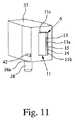
図11は、キャリヤ5上に配置する前の1つの入れ物37を概略斜視図で示している。好ましくは、入れ物37は、本質的に立方形且つ(或いは)長手方向の形態を有する。 FIG. 11 shows a schematic perspective view of one
キャリヤ5は、好ましくは、入れ物37を固定的に且つ(或いは)圧力嵌め状態で支持する。好ましくは、入れ物37は、キャリヤ5にスナップ装着され又はこの中にスナップ嵌めされる。 The
この実施形態では、入れ物37は、それぞれの入れ物37をキャリヤ5に取り付ける突起38を有している。キャリヤ5が、図9及び図10に示されているように、一連の好ましくは嵌合用又は対応の凹部39、例えばスリット又は溝を有する。図11に示されている実施形態では、特に、突起38を受け入れるボアが設けられている。特に、入れ物37をその突起38がキャリヤ5の凹部39に嵌まり込んだ状態でスナップ留めされ、クリップ留めされ、クランプされ又は圧締めされるのが良い。この目的のため、突起38は、直径が増大した好ましくは環状の部分38a等を有するのが良い。 In this embodiment, the
図12は、ボア又は凹部39を備えたキャリヤ5の好ましい実施形態を概略斜視図で示している。好ましくは、凹部及び(又は)突起38は、貯蔵器具4の内面に隣接して、内側開口部8に隣接して且つ(或いは)それぞれのインサート6を結合し、穿通し又は押す側に隣接して配置されている。しかしながら、入れ物37をキャリヤ5に結合する他の機械的解決策又は設計が可能である。 FIG. 12 shows a preferred embodiment of the
凹部又はボア39の代替手段として又はこれに加えて、キャリヤ5は、入れ物37をキャリヤ5に固定すると共に(或いは)位置合わせする手段を有するのが良い。図示の実施形態では、虚像器具4又はそのキャリヤ5は、好ましくは、リング状内壁40及び(又は)保持要素41を有する。 As an alternative to or in addition to the recess or bore 39, the
リング状内壁40は、穿通要素17を引っ込めたときにインサート6がそのキャビティ7から引き出されるのを阻止するインサート6のための当接部又は停止部を形成するのが良い。 The ring-shaped
保持要素41は、好ましくは、キャリヤ5の周囲のところに配置されており、各入れ物37を2つの隣り合う保持要素41相互間に配置できるよう好ましくは上方に突き出ている。特に、保持要素41は、入れ物37をキャリヤ5上に正確且つ(或いは)半径方向に位置合わせする。 The holding
好ましくは、入れ物37を隣り合う保持要素41相互間にスナップ嵌めし又はクランプするのが良い。この目的のため、入れ物37は、そのそれぞれの側部に設けられていて、好ましくは可撓性の且つ(或いは)アーム状の保持要素41と係合可能であり又はこれを引っ掛けることができるノーズ42又は他の適当な係合手段を有するのが良い。かくして、入れ物37をその外周部のところで保持し又は固定すると共に(或いは)穿通要素17を引っ込めたときでも傾動を回避することができるようにすることが可能である。 Preferably, the
キャリヤ5は、好ましくは、小出し器具1の初期運搬状態(出荷状態)において、即ち、小出し器具1の最初の使用前に穿通要素17を受け入れるインサート6が設けられていない状態の「ダミー」の入れ物43を有し、かかる初期運搬状態では、組立体は、図10に示す位置にあるが、穿通要素17は、ダミーの入れ物43内に延びている。 The
図13は、好ましくは中空のダミー入れ物43をキャリヤ5の部分拡大図で示している。 FIG. 13 shows a preferably
特に、ダミー入れ物43は、一方の側(スリット43a)のところが軸方向に開いていると共に(或いは)その内方側部が半径方向に開いており、その結果、穿通要素17を小出し器具1の取り付け時に、軸方向に挿入することができるようになっている。 In particular, the
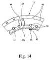
さらに、図13は、保持要素41が好ましくは、これらの自由端部のところにアンダーカット若しくは横方向に延びる部分又は入れ物37をノーズ42との係合により保持要素41相互間にしっかりと保持する他の適当な手段を備えている状態を示している。 Furthermore, FIG. 13 shows that the holding
図14は、キャリヤ5を他方の側から見た部分拡大図である。 FIG. 14 is a partially enlarged view of the
小出し器具1は、ライフスパンブロッキング(life span blocking:LSB)、即ち投与回数制限手段を有する。所定回数(投与回数又はインサート6の個数)の使用のため、この実施形態では、例えば30回又は60〜65回の投薬のために小出し器具1を用い又は作動させた後においては、それ以上の偶発的な投薬を回避するために小出し器具1を完全にロックアップする。好ましくは、小出し器具1は、多数の別個独立に働くLSBロックを有する。特に、これらロックは、圧力嵌めによりロック解除可能であると共に(或いは)ロックできる。 The
第1のLSBロックは、貯蔵器具4又はそのキャリヤ5に設けられた当接部、例えば、図14等に示されているリブ44で形成されるのが良い。この当接部は、最後のインサート6/キャビティ7を空気組立体又は穿通要素17に位置合わせしたとき、この当接部がハウジング26により提供される停止部又は小出し器具1の任意他の適当な特に剛性又は静止状態の部分に当接するので、貯蔵器具4/キャリヤ5の回転を制限する。 The first LSB lock may be formed by an abutment provided on the
第2のLSBロックが、図13に示されているように貯蔵器具4、特にキャリヤ5に形成されていて、小出し器具1の最後の使用後に解除ボタン36をその作動又は押し下げ位置にロックするスナップノーズ45により形成されるのが良い。かくして、それ以上のトリガ又それ以上のポンプ操作が阻止される。 A second LSB lock is formed in the
第3のLSBロックが、これ又貯蔵器具4、特にキャリヤ5のところに設けられていて、貯蔵器具4/キャリヤ5がその端位置に到達すると共に貯蔵器具4/キャリヤ5がその最後の位置/入れ物37に到達すると、握り19を内側又は押し位置(図7に示されている)にロックするスナップフック46により形成されるのが良い。特に、握り19は、一方の保持アーム又は2つの保持アーム57(図16に示されている)によりロック状態においてスナップフック46に引っ掛かるのが良い。 A third LSB lock is also provided at the
好ましくは、空気組立体/スライダ29と貯蔵器具4/キャリヤ5/入れ物37は、穿通要素17がそれぞれの入れ物37、キャビティ7及び(又は)インサート6を穿通し又は開放する前に穿通要素17とそれぞれの入れ物37又はインサート6の正確な位置合わせを保証するよう互いに相互作用する。この目的のため、空気組立体又はスライダ29は、好ましくは、所望の位置合わせ(微細な位置合わせ)を達成するために貯蔵器具4、キャリヤ5及び(又は)それぞれの入れ物37と相互作用する係合部分、特に二股部分47を有する。 Preferably, the air assembly /
この実施形態では、係合部分又は二股部分47は、空気組立体、特に針ホルダ30から突き出ており、この状態は、図15に詳細に示されている。係合部分又は二股部分47は、好ましくは、各インサート6と関連した位置合わせ手段又は案内部分と相互作用する。この実施形態では、これら位置合わせ手段又は案内部分は、好ましくは、突起38により形成され、これら突起は、凹部39を貫通して突き出ると共にキャリヤ5から外方又は軸方向に延びている。かくして、穿通要素17とそれぞれのインサート6との間に直接的且つ最適化された位置合わせ(微細な位置合わせ)を公差が最小限に抑えられた状態で確実に達成することができる。 In this embodiment, the engaging or
好ましくは、インサート6を上述したようにこれらの後方運動が制限され、その結果、空気組立体/スライダ29を図8に示す位置に引っ込めたときに、穿通要素17を引っ込めてそれぞれのインサートから限定的な仕方で解除することができるようになる。この制限又は制約は、好ましくは、貯蔵器具4又はキャリヤ5のところのそれぞれの停止部又は当接部によって達成される。特に、この停止部又は当接部は、リング状内壁40又は任意他の適当な手段により形成される。 Preferably, the rearward movement of the
小出し器具1は、好ましくは、使用済み又は未使用の投与分又は操作をカウントし又は示すためのカウンタ又は計数器を有する。好ましくは、計数器は、図14に示されているように貯蔵器具4、特にキャリヤ5に施された番号付け部48により形成される。番号付け部48は、ハウジング26のそれぞれの窓又は透明な部分(図示せず)を介して見える。 The
小出し器具1は、好ましくは、1回分の調合薬2の放出をトリガし(解除ボタン36を作動させることにより)、ばね28が前方に動き、ガス又は空気がそれぞれのインサート6中に送り込まれたとき、空気組立体、特に穿通要素17の逆戻り行程を阻止する手段を有する。好ましくは、この手段は、握り19を引くことができないようロックすることによって実現される。特に、握り19は、結合解除されなければならず、その後にこれを引くことができる。この実施形態では、結合解除は、握り19の一部分49を押し下げることにより、特に、握り19の互いに反対側の部分49を互いに押すことにより達成でき、その結果、握り19とハウジング26との間のそれぞれのアンダーカット又はスナップ係合をロック解除できるようになる。特に、握り19は、図16に示されているように2つの握り部分又は半部50から成る。好ましくは、各半部は、スナップ部分51と関連した可撓性の又は敏感な部分49を有する。スナップ部分は、図16に概略的に示されているようにハウジング26に形成された凹部又はアンダーカット51a内に嵌まり込んで握り19を押し位置にロックすることができる(図16は、握り19を引き位置で示している)。 The
小出し器具1は、好ましくは、使用済みインサート6を動かし又は押してこれらインサートをこれらそれぞれのキャビティ7又は入れ物37内に戻す手段を有する。この手段は、好ましくは、少なくとも1つの好ましくは静止した且つ(或いは)剛性の案内要素52、この場合、多数のリブ状案内要素52から成り、これら案内要素は、貯蔵器具4の外周部に隣接してマウスピース24の後に、特に、図17に示されているようにハウジング26の一方の半部53上又はこの中でハウジング26内に配置されている。貯蔵器具4とハウジング26又は案内要素52の相対運動により、案内要素52の傾斜面52aは、使用済みインサート6に圧力を及ぼし又はこれを押して好ましくは多数のステップをなして貯蔵器具4又はそのそれぞれのキャビティ7又は入れ物37内に戻す。代替的に又は追加的に、インサート6の傾斜部分11cを用いて使用済みインサート6を動かし、これに圧力を及ぼし又は押圧して特に好ましくは静止した案内要素52等と協働してこれらのキャビティ7内に戻しても良い。 The
小出し器具1は、好ましくは、能動型粉末吸入器であり、即ち、粉末は、加圧ガス、特に空気により放出される。それにもかかわらず、小出し操作は、患者(図示せず)の吸入又は吸息によってトリガされるのが良い。特に、小出し器具1は、吸入又は吸息を検出する検出手段及び(又は)それぞれの投与分の小出しをトリガするトリガ手段を有する。 The
好ましくは、検出手段は、患者が吸息したときに、小出し器具、特にマウスピース24を通って流れる空気に関する圧力、圧力降下、速度、速度の増大又は何らかの関連の値のうちの少なくとも1つを検出するセンサ55から成る。 Preferably, the detection means provides at least one of pressure, pressure drop, speed, speed increase or some related value relating to the air flowing through the dispensing device, in particular the
患者の吸息を指示するそれぞれの検出信号は、加圧ガスによるそれぞれの投与分の小出しをトリガするためにトリガ手段によって用いられるのが良い。特に、トリガ手段は、ガスを加圧する手段、特に空気ポンプ18、ガス供給ライン、穿通要素17等に関連したコントローラ54及び(又は)弁56から成り、その結果、それぞれの投与分の調合薬2を小出しするためにそれぞれの貯蔵チャンバ10等に、そしてこれを通る加圧ガスの流れの開始を制御し又はトリガすることができるようになる。 Each detection signal indicating patient inhalation may be used by a triggering means to trigger dispensing of each dose with pressurized gas. In particular, the triggering means consists of means for pressurizing the gas, in particular the
好ましくは、トリガ手段は、電気的、電子的、空気圧的又は機械的に働く。例えば、検出手段及びトリガ手段は、マウスピース24内の圧力が患者の吸息に起因して低下すると、入れ物37、インサート6及び(又は)貯蔵チャンバ10を通る加圧ガスの供給源を開く適当な弁65によってだけで形成されるのが良い。この場合、弁56は、好ましくは、加圧ガスの流れが停止し又はガス圧力が適当な圧力限度に達し又はこれを下回るまで開いたままである。かかる機能は、電気コンポーネント又は電子コンポーネントを用いないで実現できる。 Preferably, the trigger means works electrically, electronically, pneumatically or mechanically. For example, the detecting means and triggering means may open a source of pressurized gas through the
多数の他の仕組みの採用が可能である。別の実施形態によれば、密封された外側ケースが、例えばゴムで作られていて、一方の面が内側に向き、他方の面が大気にさらされた状態でその壁の中に設けられた可撓性ダイアフラムを有することができる。機械的利点(力の増大)を有するリンク装置が、ダイアフラムを張力要素32(図8及び図9)又は弁56若しくは任意他の適当な手段に連結してガス供給源を制御する。ユーザ又は患者がマウスピース24を介して吸入すると、密封されたケースは、ダイアフラムが曲がってケース内に入る原因となる圧力減少をもたらし、かかる圧力減少は、機械的リンクを作動させ又はこれに作用し、かくして、特に張力要素32を解除し、弁56を開くなどして小出しをトリガする。 Many other mechanisms are possible. According to another embodiment, the sealed outer case is made of, for example, rubber and is provided in the wall with one side facing inward and the other side exposed to the atmosphere. It can have a flexible diaphragm. A linkage having mechanical advantages (increased force) couples the diaphragm to the tension element 32 (FIGS. 8 and 9) or
別の実施形態によれば、フラップをマウスピース24内に密封的に位置決めすると共に機械的利点又は力の増大を有するリンク装置により張力要素32、弁56等に連結されるのが良い。ユーザ又は患者が吸入すると、空気流量/圧力の差により、リンクを作動させ又は動作させるフラップが開かれ又は作動し、かくして、特に張力要素32を解除し、弁56を開放するなどして小出しがトリガされる。 According to another embodiment, the flap may be sealingly positioned within the
別の実施形態によれば、電子システムが用いられる場合がある。感圧アクチュエータを張力要素32に連結するのが良く、その結果、ユーザ又は患者の吸入又は吸息を検出したとき、張力要素32を解除することができるようになる。 According to another embodiment, an electronic system may be used. A pressure sensitive actuator may be coupled to the
好ましくは、自動トリガ又は小出しは、小出し器具1を作動させると共に(或いは)小出しが特に解除ボタン36又は任意他のアクチュエータを作動させることにより可能になった場合にのみ可能であり、その後、トリガ手段は、最終的に、吸息が検出されたときに小出しをトリガすることができる。 Preferably, automatic triggering or dispensing is possible only when the
好ましくは、握り19と張力要素32は、直接的又は間接的に相互作用し、その結果、握り19を引いてばね28を圧縮することによって張力要素32を動かすことができるが、小出しをトリガしたとき、握り19の動きがなくても、張力要素32を圧縮解除されたばね28により定位置に戻すことができるようになる。この目的のため、張力要素32は、好ましくは、特に握り19により形成されたスリット部分58内に嵌まり込む。 Preferably, the
以下において、本発明の好ましい実施形態について説明する。以下の説明は、これまでの説明、特徴、特性及び観点が、好ましくは、それぞれの繰り返し又は説明が省かれている場合であっても、追加的に、それぞれ又は同様に当てはまるよう関連の違いに焦点を当てている。 In the following, preferred embodiments of the present invention will be described. The following description is based on related differences so that the previous description, features, characteristics and aspects preferably apply to each or similarly, even if each repetition or description is omitted. Focused.
図18は、貯蔵器具4を概略斜視図で示している。図示に当たり、インサート6及び密封材9は省かれている。 FIG. 18 shows the
入れ物37(ここでは、入れ物37の幾つかの部分)及び(又は)キャビティ7は、第1の群及び第2の群を形成している。これら群は、軸方向に且つ(或いは)割送り方向に対して横方向にオフセットしている。代替的に又は追加的に、これら群は、好ましくは、2つのオフセットした列、平面及び(又は)円をなして延びている。 The container 37 (here, some parts of the container 37) and / or the
この実施形態では、好ましくは全ての入れ物37は、各々、特に互いに上下に/軸線Aに対して軸方向にオフセットした状態で且つ(或いは)割送り方向に対して横方向に位置した2つの別々のキャビティ7を有している。 In this embodiment, preferably all the
「割送り方向」という用語は、好ましくは、貯蔵器具4を或る1つの入れ物37、キャビティ7又はインサート6から次の入れ物、キャビティ又はインサートに段階的に動かし、特に回転させる方向を意味しており、その結果、それぞれの薬剤2の投与分を次々に放出することができるようになっている。好ましい構成例の場合、割送り方向は、接線方向且つ(或いは)円周方向に向いている。 The term “indexing direction” preferably means the direction in which the
この実施形態では、入れ物37は、先の実施形態を参照して既に説明したように、共通キャリヤ5に取り付けられている。しかしながら、上述したように他の設計も可能である。特に、貯蔵器具4又はキャリヤ5は、キャビティ7を形成し又はこれらを支持しても良い。貯蔵器具4は、2つの群について2つのキャリヤ5を有するのが良い。各キャビティ7は、別個の入れ物37によって形成されるのが良い。 In this embodiment, the
この実施形態では、キャビティ7及びかくしてインサート6(図示せず)の第1の群は、キャビティ7の下側の環状構造体、即ち、キャリヤ5に隣接して位置するキャビティ7によって形成されるのが良く、第2の群は、キャビティ7又はそれぞれのインサート6の軸方向にずれたリング構造体、即ち、キャリヤ5から見て他のものよりも軸方向により遠くに位置するキャビティ7によって形成されるのが良い。 In this embodiment, the
かくして、キャビティ7(又は、これらキャビティ7を形成する入れ物37のそれぞれの部分、ここでは下側部分)の第1の群は、第1の平面内に且つ(或いは)第1の円又は列に沿って(図18に示す実施形態では、本質的に平べったいキャリヤ5に隣接して且つ(或いは)これに平行に)配置される。キャビティ7(又は、これらキャビティ7を形成する入れ物37のそれぞれの部分、ここでは上側部分)の第2の群は、第2の平面内に配置されると共に(或いは)第2の列又は円に沿って、好ましくは、第1の平面、円及び(又は)列から間隔を置くと共に(或いは)これに平行に、特に、第1の群から軸方向に且つ(或いは)この実施形態では割送り方向に対して横方向にオフセットした状態で延びる。 Thus, the first group of cavities 7 (or the respective parts of the
好ましくは、貯蔵器具4は、入れ物37及び(又は)キャビティ7の両方の群を収容した取り付けユニットを形成している。この実施形態では、第1の群の少なくとも1つのキャビティ7及び第2の群の少なくとも1つのキャビティ7は、共通入れ物37によって形成されている。この場合、入れ物37は、共通キャリヤ5に取り付けられている。しかしながら、他の構成上の手段が可能である。例えば、両方の群の全てのキャビティ7は、貯蔵器具4の1つの共通のキャリヤ5、ハウジング等によって形成されても良い。さらに、第1の群と第2の群は又、任意他の適当な仕方で互いに連結されても良い。本発明では、「相互に連結され」という用語は、好ましくは、キャビティ7の第1の群と第2の群が互いに剛性的に連結されることを意味している。 Preferably, the
この実施形態では、キャビティ7及びかくしてインサート6は、好ましくは互いに上下に一対ずつ、即ち軸方向整列状態をなして配置されている。しかしながら、円周方向オフセットを提供することも可能である。これについては別の実施形態を参照して後で説明する。 In this embodiment, the
図19は、図18に示されているような貯蔵器具4又はこれに類似した貯蔵器具を備える本発明の小出し器具1を非常に概略的に断面で示している。図19は、空気組立体/スライダ29を軸方向運動方向及び(又は)空気ポンプを作動させたときのベロー27及び(又は)ばね28の長手方向又は運動方向に対して横方向の平面内に位置した状態で示している。 FIG. 19 very schematically shows in section a
図示の実施形態では、貯蔵器具4を割送り方向において前方に動かし、特に軸線A回りに回転させて同一の群の或る1つの入れ物37、キャビティ7又はインサート6(図示せず)を次の入れ物、キャビティ又はインサートまで動かすことができる。 In the illustrated embodiment, the
さらに、貯蔵器具4は、第1の群から第2の群に変え又は第2の群から第1の群に変えるために、第1の位置、具体的には図19に示された上方位置と、第2の位置、例えば、特に図19に破線で示された下方位置との間で特に軸方向に動くことができる。小出し器具1は、貯蔵器具4の所望の、好ましくは軸方向運動が一方の群から他方の群への変更を可能にするよう案内手段、運搬機構体等を有する。この実施形態では、この案内手段又は運搬機構体は、軸方向ガイド59、好ましくは少なくとも1つのばねによって形成された少なくとも1つの付勢手段60及び(又は)キー又はロック手段61を有している。 Furthermore, the
小出し器具1は、好ましくは、貯蔵器具が第1の位置から第2の位置に自動的に且つ(或いは)第1の群の最後の入れ物37、キャビティ7又はインサート6が用いられ、開放され且つ(或いは)空にされたときにのみ、特に貯蔵器具4が更に割送りされ、かくして移行位置に達したとき(特に、キー又はロック手段61が、移行位置でのみ第1の位置から第2の位置への移動を可能にする)且つ(或いは)空気組立体/穿通要素17を最後に用いられたインサート6/キャビティ7から引っ込めたときに動くよう設計されている。 The
特に、貯蔵器具4は、付勢手段60の力(ばね力)等により、第1の位置から第2の位置に又は第2の位置から第1の位置に動くことができる。 In particular, the
かくして、非常に簡単な作動及び(又は)大きな容量が可能である。 Thus, very simple operation and / or large capacity is possible.
小出し器具1を上述の小出し器具1として用いることができる。第1の群の最後のインサート6又は投与分を開き、用い且つ(或いは)小出ししたとき又は後、小出し器具1は、好ましくは、次の使用前に又はそれと共に、或いは、追加の操作、作動等により第2の群に自動的に切り替わる。この場合、小出し器具1を第1の群の場合と同様な仕方で更に用いることができる。かくして、容量を大幅に増加させることができ、特に2倍にすることができる。例えば、第1の群は、約15〜50個のインサート6及び(又は)調合薬2の約15〜50回の投与分を有することができる。この場合、小出し器具1の全容量を、好ましくは第1の群と同一の第2の群の追加のインサート6又は調合薬2の投与分を考慮して、約30〜100個のインサート6又は薬剤2の約30〜100回の投与分まで2倍にすることができる。 The
注目されなければならないこととして、第1の群と第2の群のインサート6/投与分の数は、互いに異なっていても良い。 It should be noted that the number of
さらに、互いに異なる調合薬2を第1及び第2の群に且つ(或いは)所望ならば各群内に用いることができる。 Furthermore,
この実施形態では、キー又はロック手段61は、例えば、カム手段又は他のキャッチ手段等、特に、好ましくは、貯蔵器具4のところ又はそのキャリヤ5のところに形成された半径方向突起62及び好ましくは図20に概略的に示されているように相補するカム又はキャッチ若しくは案内手段、特にハウジング26の内側円周方向側部に形成されたリング壁64に設けられている軸方向スリット又は溝を有する。図20においては、ハウジング26の外側周囲壁及び他のコンポーネントは、図面を分かりやすくするために省かれていることが注目されなければならない。 In this embodiment, the key or locking means 61 are, for example, cam means or other catch means, such as, preferably,
この実施形態では、軸方向溝63は、これ又小出し器具1のハウジング26又は任意他の適当な部品によって形成された2つの円周方向スリット又は溝65,66を相互に連結している。 In this embodiment, the
キー又はロック手段61は、好ましくは、特に貯蔵器具4が割送り方向において第1の群の最後の入れ物37、キャビティ7及び(又は)インサート6の後で次の割送り位置として(これは、移行位置とも呼ばれる)に達したとき、貯蔵器具4が一回転位置でのみ第1の位置から第2の位置に又は第2の位置から第1の位置に動くことができるよう設計されている。これは、好ましくは、この実施形態では、貯蔵器具4が第1の位置にあるとき、突起62が第1の溝65と嵌合し又はこの中に突き出るので達成される。突起62が第1の溝65に沿って又はこの中で動くことができるので貯蔵器具4を動かし若しくは回転させ又は割送りすることができる。しかしながら、突起62は、円周方向位置が移行位置でのみ軸方向溝63の円周方向位置に合うように円周方向に分布して設けられている。移行位置に達すると、付勢手段60は、貯蔵器具4を自動的に第1の位置から第2の位置に動かすことができ、この場合、軸方向にずらすことができ、突起62は、軸方向溝63を経て第2の円周方向溝66に動く。すると、貯蔵器具4は、その第2の位置に達しており、この貯蔵器具を必要ならば次の使用中、更に回転させることができる(割送りすることができる)。 The key or locking means 61 is preferably used as the next indexing position after the
注目されなければならないこととして、貯蔵器具4をばね力だけで第1の位置から第2の位置に又は第2の位置から第1の位置に動かすことができる。代替的に又は追加的に、貯蔵器具4を好ましくは貯蔵器具4を逆方向に付勢するばね力(付勢手段)60に抗して、確動ガイド又は案内湾曲部により軸方向に第2の位置から第1の位置に又は第1の位置から第2の位置に動かすことができる。この確動ガイド又は案内湾曲部は、適当な仕方で、例えば螺旋に延びる溝63,65又は66及びこれらとそれぞれ嵌合する例えば突起62等により形成されるのが良い。しかしながら、他の構成上の手段が可能である。 It should be noted that the
図19及び図20に示された小出し器具1は、一般に、上述したような半径方向に動くことができるグリップ又はアクチュエータ19を備えるのが良い。 The
小出し器具1は、好ましくは、図19に概略的に示されているような回動可能なアクチュエータ、ハウジング部分又はカバー68を有する。このカバー68は、所望に応じて又は上述したように運搬機構体33及び(又は)空気組立体、空気ポンプ18又はスライダ29を作動させ又は駆動するために、特に軸線A回りに回動可能である。例えば、カバー68は、カバー68に相互に連結され又はこれによって形成されてこれと共に回動可能である部分に形成された確動ガイド手段、例えば溝又は凹部69、特に制御湾曲部を有するのが良く、その結果、スライダ29及び引っ張り要素32を例えば所望に応じて制御湾曲部内への係合部分(図示せず)の嵌合により半径方向に且つ(或いは)確実に動かすことができるようになっており、その目的は、所要のタイミングで穿通要素17及び付勢ばね28の所望の運動を達成することにある。 The
好ましくは、小出し器具1は、貯蔵器具4が軸方向に割送りされると共に(或いは)動かされ、連結要素が対応のインサート6に連結され又はこれから引っ込められ、インサート6がそのキャビティ7から動かされ又は外方に押し出され、且つ(或いは)小出し器具1又はそのカバー68を回動させ、開き且つ(或いは)閉じることにより空気ポンプ18/空気組立体を動かすと共に(或いは)ばね28を付勢するよう設計されている。この種の作動方式は、全ての実施形態に利用できる。 Preferably, the
しかしながら、他の伝達手段、構成上の手段、駆動手段等を使用することができる。 However, other transmission means, structural means, drive means, etc. can be used.
図18〜図20を参照して説明した好ましい実施形態では、機構体20又は連結要素/穿通要素17は、その運動平面を変更せず、貯蔵器具4は、第1の群から第2の群又は第2の群から第1の群への変更を行うために軸方向に動かされ又はずらされる。しかしながら、連結要素/穿通要素17を特に貯蔵器具4の回転軸線Aに関して軸方向に又はインサート6を連結し、押し又は穿通するためのその通常の運動方向に対して横方向に第1の運動平面から第2の運動平面に動かして第1の群から第2の群又は第2の群から第1の群への変更を行うことも可能である。これについては、本発明の別の実施形態を示す図21〜図23を参照して説明する。 In the preferred embodiment described with reference to FIGS. 18-20, the
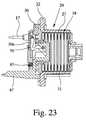
図21及び図22は、小出し器具1の空気組立体/スライダ29を示している。図21は、穿通要素17をその第1の又は下方位置で示している。図22は、穿通要素17をその第2の又は上方位置で示している。図23は、穿通要素17がその第2の又は上方位置にある状態の空気組立体/スライダ29の部分断面図である。
別の実施形態では、穿通要素17は、穿通要素17の連結方向に対して横方向に、特に垂直に動くことができる。「連結方向」という用語は、インサート6を動かし又は押すと共に(或いは)入れ物37、キャビティ7又はインサート6を穿通し又は開放する穿通要素17の通常の運動、この場合、長手方向又は半径方向運動を意味している。21 and 22 show the air assembly /
In another embodiment, the piercing
穿通要素17の横方向運動を可能にするため、針ホルダ30は、好ましくはこの方向にずれることができる可動ホルダ30aを有し、特に、ホルダは、この方向に摺動することができる。この場合、針ホルダ30又はスライダフレーム31は、針ホルダ30それ自体又は可動ホルダ30aが穿通要素17と一緒に所望の方向に摺動することができるよう設計されており、その目的は、上述したように第1の群から第2の群に又は第2の群から第1の群への変更を可能にすることにある。 In order to allow lateral movement of the penetrating
可動ホルダ30aは、好ましくは、適当な付勢手段、この場合軸方向ばね67によって第2の位置に向かって付勢される。可動ホルダ30aは、貯蔵器具4が、第1の群から第2の群への変更が行われるべきその移行位置に達するまで、適当なロック手段(図示せず)によって第1の位置に保持され又はロックされる。次に、ロック手段は、付勢手段又は軸方向ばね67が可動ホルダ30aを穿通要素17と一緒に第1の位置から第2の位置に動かすよう開放され又は解除される(好ましくは、貯蔵器具4が移行位置に達すると、自動的に)。 The
図23は、可動連結要素/穿通要素17が好ましくは、可撓性連結部材、この場合管70により空気ポンプ18、特にベロー27に連結されていることを概略部分断面図で示している。しかしながら、他の構成上の手段も又可能である。 FIG. 23 shows in a schematic partial cross-section that the movable connecting element / penetrating
連結部材は、穿通要素17を空気ポンプ18に流体結合していて、加圧ガス(空気)をベロー27から連結部材を介して穿通要素17に供給して空気を穿通されたインサート6に供給することができるようになっている。 The connecting member fluidly couples the penetrating
図23に関し、注目されなければならないこととして、ベロー27は、好ましくは、特にリング部分等によって針ホルダ30にクランプされ又は連結される。この実施形態では、針ホルダ30は、好ましくは、ベロー27の関連の端部を保持する連結部分(円筒形突起又は円筒形部分)を有する。ベロー27は、他端部が引っ張り要素32に連結されている。好ましくは、この連結は、クリップ止め、クランプ又は任意他の適当な連結手段によって達成される。図示の実施形態では、引っ張り要素32は、好ましくは、ジャーのように設計され、ジャーの底部は、ベロー27の関連の軸方向端部に連結されている。かくして、ジャーの側壁は、ベロー27のためのガイドを形成している。しかしながら、他の構成上の手段も又可能である。 With respect to FIG. 23, it should be noted that the
注目されなければならないこととして、連結要素は、各群の入れ物37/キャビティ7/インサート6に個々に又は独立して連結可能である。特に、連結要素は、一方の群のインサート6に次々に連結し、次に、他方の群に切り替わることができる。しかしながら、連結要素は、一方の群の1つのインサート6に択一的に結合し、次に、次の群の1つのインサートに結合し、例えば、群相互間を多数回切り替わることも又可能である。この場合、一方の群のキャビティ7/インサート6は、他方の群のキャビティ7/インサート6に対して円周方向にオフセットしているのが良い。しかしながら、他の構成上の手段も又可能である。 It should be noted that the connecting elements can be connected to each group of
小出しが群相互間で多数回にわたって切り替わる場合、或る特定の数のインサート6又は投与分を一方の群から放出し、次に、他方の群への切り替わり後、他方の群の或る特定の数のインサート6又は投与分を放出するのが良い。この場合、小出しを第1の群に変更して戻すことなどしても良い。或る特定の数は、様々であって良く又は一定であっても良く、特に、この数は、“1”(各インサート6又は投与分後の群の変更)であっても良く、“2”(各2つのインサート6又は投与分後の群の変更)であっても良い。後者の場合、作動順序は、例えば次の通りであり、即ち、第1の群への変更(連結要素に対する貯蔵器具4の軸方向運動による)を行い、第1の群の1つのインサートから1回の投与分の放出(連結要素を連結方向に動かしてこれをインサート6に連結し、インサート6を軸方向外方に押すこと、インサート6から投与分の放出後に連結要素を引っ込めることを含む)を行い、貯蔵器具を一ステップだけ割送りし(貯蔵器具4の回転による)、第1の群の次のインサート6の別の投与分を放出し、第2の群に切り換え、第2の群の1つのインサート6から投与分の放出を行い、貯蔵器具4を一ステップだけ割送りし、第2の群の次のインサート6から別の投与分の放出を行い、第1の群に切り換えて戻ること等であるのが良い。 If the dispenser switches multiple times between groups, a certain number of
第1及び第2の群は、互いに異なる数の投与分、キャビティ7及び(又は)インサート6を含んでも良いことは注目されなければならない。特に、この場合、或る群に関する或る特定の数は、互いに異なっていても良い。 It should be noted that the first and second groups may include different numbers of doses,
注目されなければならないこととして、一般に、又、好ましい実施形態では、一方の群の投与分を互いに別個独立に小出しすることができると共に(或いは)第1の群の投与分を第2の群の投与分と別個独立に又はこれと択一的に小出ししても良い。 It should be noted that, generally and in preferred embodiments, one group of doses can be dispensed separately and independently of each other and / or the first group of doses can be dispensed with the second group. It may be dispensed separately from the dose or alternatively.
先の実施形態では、貯蔵器具4か連結要素/穿通要素17かのいずれかは、第1の群と第2の群との間で切り替わるようにするために軸線Aの方向に動くことができる(少なくとも、所与のコンポーネントと一緒に)。しかしながら、かかる相対運動を図示のように且つ以下の実施形態において説明するように回避することができる。 In the previous embodiment, either the
図24は、小出し器具1/貯蔵器具4の別の実施形態を略図で示している。この場合、インサート6は、連結要素を連結することができる連結部分71を有している。連結部分71は、一共通平面で(例えば、両方の群又はリング相互間で)終端すると共に(或いは)軸線Aの方向(半径方向)における又は連結要素の連結運動方向(半径方向又は長手方向)に対する横方向における貯蔵器具4/キャリヤ5に対する連結要素の相対運動又は貯蔵器具4の前方運動(円周方向運動)を行わないで、連結要素を連結部分71に連結することができるよう配置され又は設計され(例えば、傾けられ)ている。かくして、穿通要素17を例えば図15に示されているように、ホルダ30によって保持することができる。 FIG. 24 schematically shows another embodiment of the
連結部分71は、好ましくは、半径方向内方に延びると共に(或いは)軸方向及び(又は)半径方向延長部を有し又は形成する。しかしながら、他の構成上の手段も又可能である。 The connecting
好ましくは、連結部分71は、インサート6と一体に形成され又はインサート6によって形成され、特に、ベース部材11である。 Preferably, the connecting
好ましくは、連結部分71は各々、貯蔵チャンバ10に通じていて、穿通要素17が連結部分71の端部を穿通すると、穿通要素17と貯蔵チャンバ10との間の流体結合を可能にする連結チャネルを有する。 Preferably, the connecting
好ましくは、連結部分71は、択一的に第1の群及び第2の群の一部をなす。 Preferably, the connecting
好ましくは、一方の群のキャビティ7/インサート6は、他方の群に対して円周方向にオフセットしている。しかしながら、キャビティ7/インサート6は又、連結部分71が適当な仕方でオフセットしている場合、互いに上下に一対ずつ(即ち、円周方向のオフセットなく)配置されても良い。 Preferably, one group of
指摘されなければならないこととして、本発明により、種々の技術上の手段がキャビティ7/インサート6の少なくとも2つの互いにオフセットした群からの放出を可能にすることができる。群又は貯蔵器具4をオフセット方向(群相互間での切り換え方向、この場合、割送り方向及び連結要素の連結方向に対して横方向、又は軸方向、即ち軸線Aの方向)に動かすことが可能である。連結要素を群相互間の切り換えのためにオフセット方向に動かすことが可能である。群相互間での切り換えのためにオフセット方向における貯蔵器具4に対する連結要素又は空気ポンプ18の運動又はこれとは逆の関係の運動を回避するために、2つのオフセットした連結要素を択一的に用いるのが良く又は一共通平面における連結(連結部分71による)を用いても良い。しかしながら、他の構成上の手段も又可能である。 It has to be pointed out that according to the invention various technical means can enable the discharge from at least two mutually offset groups of
図25〜図27を参照して本発明の別の実施形態について説明する。図25は、空気組立体/空気ポンプ18/スライダ29を概略斜視図で示している。この場合、小出し器具1は、多数の又は2つの連結要素、特に穿通要素17を有している。好ましくは、両方の連結要素は、同一の針ホルダ30、スライダ29及び(又は)空気ポンプ18に取り付けられ又はこれらによって支持される。好ましくは、両方の連結要素は、互いに剛性的に連結されると共に(或いは)一緒にしか動くことができず且つ(或いは)連結又は半径方向にしか動くことができない。 Another embodiment of the present invention will be described with reference to FIGS. FIG. 25 shows the air assembly /
連結要素は、好ましくは、円周方向に、即ち、貯蔵器具4の前方運動方向又は回転方向にオフセットしている。 The connecting element is preferably offset in the circumferential direction, i.e. in the direction of forward movement or rotation of the
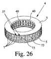
図26は、キャビティ7/インサート6(インサート6は、図26には示されていない)の2つの群の二重リング構造体を備えた貯蔵器具4を概略斜視図で示している。図27は、図26の貯蔵器具4の内側部分の拡大図である。 FIG. 26 shows in schematic perspective view a
好ましくは、貯蔵器具4は、各群の隣り合うキャビティ相互間に位置する受け入れ部分72を有している。受け入れ部分72は、連結要素を閉鎖するために連結要素を受け入れ、特に、連結要素の先端部を受け入れるようになっている。この目的のため、受け入れ部分72は、止まり穴等として形成されるのが良い。例えば、受け入れ部分72は、密封スリーブ等で形成されるのが良く又は受け入れ部分は各々、密封スリーブ等を有する。しかしながら、他の構成上の手段も又可能である。 Preferably, the
図示の実施形態では、受け入れ部分72をハウジングにより且つ(或いは)特に隣り合う入れ物37相互間に形成するのが良い。受け入れ部分72内に挿入された連結要素の非常に良好な密封を保証するために、受け入れ部分72に任意適当な密封材料、特にエラストマー等を充填するのが良い。 In the illustrated embodiment, the receiving
2つの連結要素の互いに対する円周方向オフセット及び(又は)2つの群のキャビティ7に対する2つの連結要素の円周方向オフセットにより、連結要素のうちの1つだけ(第1の連結要素)が、その関連の群の1つのインサート6に連結され、他方の、即ち第2の連結要素は、スライダ29がその前方位置にあるとき、例えば、小出し器具1の作動状態では他方の群の受け入れ部分72のうちの1つの中に受け入れられる。かくして、小出し中、第1の連結要素を介してのみ放出される。というのは、他方の(第2の)連結要素は、関連の受け入れ部分72によって閉鎖されている(十分に閉鎖されている)からである。 Due to the circumferential offset of the two coupling elements relative to each other and / or the circumferential offset of the two coupling elements relative to the two groups of
次の小出し作業のため、第1の連結要素は、閉じられ、第2の連結要素は、第2の群の1つのインサート6に連結される。 For the next dispensing operation, the first connecting element is closed and the second connecting element is connected to one
したがって、連結要素は、受け入れ部分72によって択一的に閉鎖され、その関連の群のインサート6に連結され、したがって、小出しの際、ガス(空気)を常時一方の連結要素を介してのみ放出することができるようになっている。
しかしながら、連結要素を弁装置(図示せず)又は任意他の適当な手段により択一的に閉鎖することも又可能である。また、弁が空気ポンプ18から一方の連結要素だけへの択一的な流体結合部を開放することが可能である。Thus, the connecting element is alternatively closed by the receiving
However, it is also possible to alternatively close the connecting element by means of a valve device (not shown) or any other suitable means. It is also possible for the valve to open an alternative fluid coupling from the
図25〜図27に示された実施形態では、2つの連結要素は、円周方向にオフセットしており、第1の群のインサート6は、互いに上下に、即ち、円周方向にオフセットなく、第2の群のインサート6の上方に一対ずつ配置されている。しかしながら、連結要素を互いに上下に(即ち、円周方向のオフセットなく)配置すると共に第1の群と第2の群との間の円周方向オフセットをもたらすことも可能である。この場合、機能は、上述したのと同一であり、即ち、連結要素は、択一的にインサート6に連結されて択一的に第1の群の1つのインサート6と第2の群の1つのインサート6が互いに連結される(穿通される)よう閉じられる。 In the embodiment shown in FIGS. 25 to 27, the two connecting elements are offset in the circumferential direction, and the first group of
好ましくは、貯蔵器具4は、2つのキャリヤ5を有し、入れ物37は、図26に示されているようにこれらキャリヤ相互間に配置される。これにより、好ましくは予備充填された入れ物37を容易にキャリヤ5相互間に取り付けることができる非常に頑丈な構造の実現が可能である。好ましくは、一方のキャリヤ5は、特に内側リング壁40によってインサート6の第1の群のための内側当接部又は停止部を形成し、他方のキャリヤ5は、好ましくはその内側リング壁40によって第2の群のインサート6のための内側停止部又は当接部を形成する。 Preferably, the
好ましくは、キャビティ7/インサート6の両方の群は、互いに剛性的に連結されると共に(或いは)、取り付けユニットを形成する。 Preferably both groups of
好ましくは、各入れ物37は、2つのキャビティ7を形成する。 Preferably, each
好ましくは、第1の群のキャビティ7/インサート6と第2の群とキャビティ7/インサート6は、共通の中間壁73によって分離されているに過ぎない。これにより、非常にコンパクトな構成の実現が可能である。 Preferably, the first group of
好ましくは、インサート6は、一方の環状構造体のキャビティ7、インサート6及び投与分の数を最適化し又は増大させることができるよう円周方向に非常に小さなキャビティ7を形成することができるようにするために、円周方向にできるだけ薄い。キャビティ7及びインサート6の断面が長方形である場合、小さい方の側部(辺)は、好ましくは、円周方向に延びる。これにより、キャビティ7及びインサート6の密集的配置度を最適化することができる。しかしながら、他の構成上の手段も又可能である。 Preferably, the
また、2つの互いに異なる調合薬2を同時に又は択一的に放出するために2つの連結要素を備えた小出し器具1を使用できることは、注目されるべきである。特に、第1の群と第2の群は、互いに異なる調合薬2を含むことができる。「互いに異なる」という用語は、調合薬2が少なくとも1つの関連の特徴又は特性、例えば濃度、有効成分、稠度、量等が互いに異なることを意味する。 It should also be noted that the
互いに異なる平面内に位置する互いに異なる群からそれぞれの調合薬2を同一の共通マウスピース24中に放出する場合、互いに異なる平面を相互に切り換えることが妥当である場合がある。 When the
特に、小出し器具1又は貯蔵器具4が投与分を小出しする2つの互いに異なる平面内に位置するキャビティ7/インサート6/投与分を有する場合、図28及び図29に示されているような切り換え装置74を出口経路、特にマウスピース24内に設けて2つの平面相互間を切り換えるのが良い。この切り換えは、流れ方を最適化できると共に(或いは)用いられていない平面内におけるキャビティ7/インサート6の群の良好な包封を保証することができる。 In particular, if the
特に、切り換え装置74は、マウスピース24の入口を覆うことができると共に(或いは)次の投与分を放出する群又は平面に応じて、択一的にしか開くことができない2つの開口部75を形成することができる。 In particular, the switching
図28は、切り換え装置74と関連したマウスピース24を分解組立て図で示している。図29は、切り換え装置74が取り付けられたマウスピース24を示している。 FIG. 28 shows the
切り換え装置74は、好ましくは、互いに異なる平面と関連していて、択一的に開くことができる2つの出口開口部75を有する。この実施形態では、出口開口部75は、切り換え装置74の切り換え部材76に形成されている。切り換え部材76は、好ましくは、ブラケット77により又は任意他の適当な仕方でこの場合マウスピース24内に摺動可能に保持されている。 The switching
この実施形態では、切り換え装置74は、出口スリット78を有する。出口スリットと出口開口部75は、可動切り換え部材76の位置に応じて、出口開口部75のうちの一方のみが常時開かれ、他方の出口開口部75が閉じられるように互いに関連している。出口開口部75のうちの一方が第1の群の平面内に配置され、他方の出口開口部75が第2の群の平面内に配置されているので、切り換え装置74は、切り換え部材76の位置に応じて、群のうちの一方についてのみ常時、マウスピース24又は任意他の出口との流体結合を可能にする。 In this embodiment, the switching
図示の実施形態では、切り換え部材76は、本質的に二重のTの形態をしている。好ましくは、切り換え部材76は、両方の側部又は2つの反対側の側部が摺動可能に保持される。 In the illustrated embodiment, the switching
上述したように、出口開口部75は、出口開口部75のうちの一方のみが常時開いているように出口スリット78と協働する。これは、この実施形態では、好ましくは、出口開口部75が切り換え部材76の切り換え運動に関して互いに対してオフセットしているので達成され、この場合、出口スリット78は、オフセットなく且つ(或いは)両方の平面上に横方向に延びる。しかしながら、他の構成上の手段も又可能である。 As described above, the
切り換え部材76は、好ましくは、1つのインサート6/キャビティ7から次のインサート6/キャビティ7への切り換えの際、貯蔵器具4の回転運動又は前方運動に関して接線方向に動くことができる。 The switching
この実施形態では、切り換え部材76は、好ましくは、一方向に並進的に動くことができる。しかしながら、他の構成上の手段も又可能である。特に、切り換え部材76は又、出口開口部75又は出口スリット78を所望の仕方で択一的に開閉するために回動可能又は回転可能であるのが良い。 In this embodiment, the switching
切り換え部材76は、捕捉装置79によってそのそれぞれの位置に保持可能である。 The switching
好ましくは、切り換え装置74又は切り換え部材76は、特に小出しが一方の群から他方の群に変わった場合又は可動針ホルダ30aを動かした場合、駆動手段又は運搬機構体33が貯蔵器具4を駆動することにより且つ(或いは)貯蔵器具4それ自体又は空気ポンプ18又はスライダ29又は可動ホルダ30aにより作動され又は駆動される。しかしながら、他の構成上の手段も又可能である。 Preferably, the switching
好ましくは、インサート6、キャビティ7及び(又は)入れ物37は、環状に配置される。図18〜図23を参照して説明した実施形態は、好ましくは、入れ物37、キャビティ7及び(又は)インサート6の二重リング構造体を備えた貯蔵器具4を提供する。しかしながら、任意他の構造体、特に直線構造体等が可能である。任意他の適当な、特に二重の列をなす構造体、例えば直線構造体、帯状構造体等を代替的に又は追加的に提供することができる。 Preferably, the
また、種々の実施形態の個々の特徴及び観点を所望に応じて互いに組み合わせることができ又は他の設計の吸入器に用いることができる。 Also, the individual features and aspects of the various embodiments can be combined with each other as desired or used in other designs of inhalers.
本発明は、吸入器には限定されず、他のアトマイザにも利用できる。したがって、「吸入器」という用語は、好ましくは、特に医療又は他の治療目的の他のディスペンサ又はアトマイザをも含むものとして広義に解釈されるべきである。 The present invention is not limited to an inhaler and can be used for other atomizers. Thus, the term “inhaler” should preferably be construed broadly to include other dispensers or atomizers, particularly for medical or other therapeutic purposes.
好ましい医薬調合物又は調合薬2の幾つかの好ましい成分及び(又は)組成が以下に列記されている。上述したように、これら調合薬は、特に粉末、最も広い意味では流体である。特に好ましくは、調合薬2は、以下を含む。 Some preferred ingredients and / or compositions of the preferred pharmaceutical formulation or
以下に列記する化合物をこれら自体で又は組合せ状態で本発明の器具に用いることができる。以下に記載する化合物に関し、Wは、薬理学的に有効な物質であり、ベータミメティック(Betamimetic)、抗コリン作用薬、コルチコステロイド、PDE4−阻害薬、LTD4−拮抗薬、EGFR−阻害薬、ドーパミン作用薬、H1−抗ヒスタミン薬、PAF−拮抗薬及びPI3−キナーゼ阻害薬の中から(例示として)選択される。さらに、Wの2つの組合せ又は3つの組合せを組み合わせて本発明の器具に用いることができる。Wの組合せは、例えば次のようなものが考えられる。
‐Wは、抗コリン作用薬、コルチコステロイド、PDE4−阻害薬、EGFR−阻害薬又はLTD4−拮抗薬と組み合わされるベータミメティックを意味する。
‐Wは、ベータミメティック、コルチコステロイド、PDE4−阻害薬、EGFR−阻害薬又はLTD4−拮抗薬と組み合わされる抗コリン作用薬を意味する。
‐Wは、PDE4−阻害薬、EGFR−阻害薬又はLTD4−拮抗薬と組み合わされるコルチコステロイドを意味する。
‐Wは、EGFR−阻害薬又はLTD4−拮抗薬と組み合わされるPDE4−阻害薬を意味する。
‐Wは、LTD4−拮抗薬と組み合わされるEGFR−阻害薬を意味する。The compounds listed below can be used in the device of the present invention by themselves or in combination. Regarding the compounds described below, W is a pharmacologically effective substance and is a betamimetic, anticholinergic agent, corticosteroid, PDE4-inhibitor, LTD4-antagonist, EGFR-inhibitor. , Selected from among dopamine agonists, H1-antihistamines, PAF-antagonists and PI3-kinase inhibitors (for example). Furthermore, two or three combinations of W can be combined and used in the device of the present invention. For example, the following combinations of W are conceivable.
-W means a beta mimetic in combination with an anticholinergic, corticosteroid, PDE4-inhibitor, EGFR-inhibitor or LTD4-antagonist.
-W means an anticholinergic agent in combination with a beta mimetic, corticosteroid, PDE4-inhibitor, EGFR-inhibitor or LTD4-antagonist.
-W means corticosteroid combined with PDE4-inhibitor, EGFR-inhibitor or LTD4-antagonist.
-W means PDE4-inhibitor combined with EGFR-inhibitor or LTD4-antagonist.
-W means EGFR-inhibitor combined with LTD4-antagonist.
ベータミメティックとして用いられる化合物は、好ましくは、アルブテロール、アルフォルモテロール、バンブテロール、ビトルテロール、ブロクサテロール、カルブテロール、クレンブテロール、フェノテロール、ホルモテロール、ヘキソプレナリン、イブテロール、イソエタリン、イソプレナリン、レボサルブタモル、マブテロール、メルアドリン、メタプロテレノール、オルチプレナリン、ピルブテロール、プロカテロール、レプロテロール、リミテロール、リトドリン、サルメファモル、サルメテロール、ソテレノール、スルホンテロール、テルブタリン、チアラミド、トルブテロール、ジンテロール、CHF−1035、HOKU−81、KUL−1248、及び
‐3−(4−{6−[2−ヒドロキシ−2−(4−ヒドロキシ−3−ヒドロキシメチル−フェニル)−エチルアミノ]−ヘキシロキシ}−ブチル)−ベンジル−スルホナミド、
‐5−[2−(5,6−ジエチル−インダン−2−イルアミノ)−1−ヒドロキシ−エチル]−8−ヒドロキシ−1H−キノリン−2−オン、
‐4−ヒドロキシ−7−[2−{[2−{[3−(2−フェニルエトキシ)プロピル]スルホニル}エチル]−アミノ}エチル]−2(3H)−ベンゾチアゾロン、
‐1−(2−フルオロ−4−ヒドロキシフェニル)−2−[4−(1−ベンジミダゾリル)−2−メチル−2−ブチルアミノ]エタノール、
‐1−[3−(4−メトキシベンジル−アミノ)−4−ヒドロキシフェニル]−2−[4−(1−ベンジミダゾリル)−2−メチル−2−ブチルアミノ]エタノール、
‐1−[2H−5−ヒドロキシ−3−オキソ−4H−1,4−ベンゾキサジン−8−イル]−2−[3−(4−N,N−ジメチルアミノフェニル)−2−メチル−2−プロピルアミノ]エタノール、
‐1−[2H−5−ヒドロキシ−3−オキソ−4H−1,4−ベンゾキサジン−8−イル]−2−[3−(4−メトキシフェニル)−2−メチル−2−プロピルアミノ]エタノール、
‐1−[2H−5−ヒドロキシ−3−オキソ−4H−1,4−ベンゾキサジン−8−イル]−2−[3−(4−n−ブチルオキシフェニル)−2−メチル−2−プロピルアミノ]エタノール、
‐1−[2H−5−ヒドロキシ−3−オキソ−4H−1,4−ベンゾキサジン8−イル]−2−{4−[3−(4−メトキシフェニル)−1,2,4−トリアゾル−3−イル]−2−メチル−2−ブチルアミノ}エタノール、
‐5−ヒドロキシ−8−(1−ヒドロキシ−2−イソプロピルアミノブチル)−2H−1,4−ベンゾキサジン−3−(4H)−オン、
‐1−(4−アミノ−3−クロロ−5−トリフルオロメチルフェニル)−2−t−ブチルアミノ)エタノール、
‐6−ヒドロキシ−8−{1−ヒドロキシ−2−[2−(4−メトキシ−フェニル)−1,1−ジメチル−エチルアミノ]−エチル}−4H−ベンゾ[1,4]オキサジン−3−オン、
‐6−ヒドロキシ−8−{1−ヒドロキシ−2−[2−(エチル4−フェノキシ−アセテート)−1,1−ジメチル−エチルアミノ]−エチル}−4H−ベンゾ[1,4]オキサジン−3−オン、
‐6−ヒドロキシ−8−{1−ヒドロキシ−2−[2−(4−フェノキシ−酢酸)−1,1−ジメチル−エチルアミノ]−エチル}−4H−ベンゾ[1,4]オキサジン−3−オン、
‐8−{2−[1,1−ジメチル−2−(2,4,6−トリメチルフェニル)−エチルアミノ]−1−ヒドロキシ−エチル}−6−ヒドロキシ−4H−ベンゾ[1,4]オキサジン−3−オン、
‐6−ヒドロキシ−8−{1−ヒドロキシ−2−[2−(4−ヒドロキシ−フェニル)−1,1−ジメチル−エチルアミノ]−エチル}−4H−ベンゾ[1,4]オキサジン−3−オン、
‐6−ヒドロキシ−8−{1−ヒドロキシ−2−[2−(4−イソプロピル−フェニル)−1,1−ジメチル−エチルアミノ]−エチル}−4H−ベンゾ[1,4]オキサジン−3−オン、
‐8−{2−[2−(4−エチル−フェニル)−1,1−ジメチル−エチルアミノ]−1−ヒドロキシ−エチル}−6−ヒドロキシ−4H−ベンゾ[1,4]オキサジン−3−オン、
‐8−{2−[2−(4−エトキシ−フェニル)−1,1−ジメチル−エチルアミノ]−1−ヒドロキシ−エチル}−6−ヒドロキシ−4H−ベンゾ[1,4]オキサジン−3−オン、
‐4−(4−{2−[2−ヒドロキシ−2−(6−ヒドロキシ−3−オキソ−3,4−ジヒドロ−2H−ベンゾ[1,4]オキサジン−8−イル)−エチルアミノ]−2−メチル−プロピル}−フェノキシ)−酪酸、
‐8−{2−[2−(3,4−ジフルオロ−フェニル)−1,1−ジメチル−エチルアミノ]−1−ヒドロキシ−エチル}−6−ヒドロキシ−4H−ベンゾ[1,4]オキサジン−3−オン、
‐1−(4−エトキシ−カルボニルアミノ−3−シアノ−5−フルオロフェニル)−2−(t−ブチルアミノ)エタノール、
‐2−ヒドロキシ−5−(1−ヒドロキシ−2−{2−[4−(2−ヒドロキシ−2−フェニル−エチルアミノ)−フェニル]−エチルアミノ}−エチル)−ベンズアルデヒド、
‐N−[2−ヒドロキシ−5−(1−ヒドロキシ−2−{2−[4−(2−ヒドロキシ−2−フェニル−エチルアミノ)−フェニル]−エチルアミノ}−エチル)−フェニル]−ホルムアミド、
‐8−ヒドロキシ−5−(1−ヒドロキシ−2−{2−[4−(6−メトキシ−ビフェニル−3−イルアミノ)−フェニル]−エチルアミノ}−エチル)−1H−キノリン−2−オン、
‐8−ヒドロキシ−5−(1−ヒドロキシ−2−(6−フェネチルアミノ−ヘキシルアミノ)−エチル)−1H−キノリン−2−オン、
‐5−[2−(2−{4−[4−(2−アミノ−2−メチル−プロポキシ)−フェニルアミノ]−フェニル}−エチルアミノ)−1−ヒドロキシ−エチル]−8−ヒドロキシ−1H−キノリン−2−オン、
‐[3−(4−{6−[2−ヒドロキシ−2−(4−ヒドロキシ−3−ヒドロキシメチル−フェニル)−エチルアミノ]−ヘキシルオキシ}−ブチル)−5−メチル−フェニル]−ウレア、
‐4−(2−{6−[2−(2,6−ジクロロ−ベンジルオキソ)−エトキシ]−ヘキシルアミノ}−1−ヒドロキシ−エチル)−2−ヒドロキシメチル−フェノール、
‐3−(4−{6−[2−ヒドロキシ−2−(4−ヒドロキシ−3−ヒドロキシメチル−フェニル)−エチルアミノ]−ヘキシルオキシ}−ブチル)−ベンジルスルホンアミド、
‐3−(3−{7−[2−ヒドロキシ−2−(4−ヒドロキシ−3−ヒドロキシメチル−フェニル)−エチルアミノ]−ヘプチルオキシ}−プロピル)−ベンジルスルホンアミド、
‐4−(2−{6−[4−(3−シクロペンタンスルホニル−フェニル)−ブトキシ]−ヘキシルアミノ}−1−ヒドロキシ−エチル)−2−ヒドロキシメチル−フェノール、
‐N−アダマンタン−2−イル−2−(3−{2−[2−ヒドロキシ−2−(4−ヒドロキシ−3−ヒドロキシメチル−フェニル)−エチルアミノ]−プロピル}−フェニル)−アセトアミドの中から選択された化合物であり、
オプションとして上記化合物のラセミ化合物、エナンチオマー又はジアステレオマー及びオプションとして上記化合物の薬理学的に容認できる酸添加塩、溶媒化合物又は水和物である。本発明によれば、ベータミメティックの酸添加塩は、好ましくは、ヒドロクロリド(塩酸塩)、ヒドロブロミド(臭化水素酸塩)、ヒドロイオジド(沃化水素酸塩)、ヒドロスルフェート(重硫酸塩)、ヒドロホスフェート、ヒドロメタンスルホネート、ヒドロニトレート、ヒドロマレエート、ヒドロアセテート、ヒドロシトレート、ヒドロフマレート、ヒドロタルトレート、ヒドロオキサレート、ヒドロスクシネート、ヒドロベンゾエート及びヒドロ−p−トルエンスルホネートの中から選択される。The compounds used as beta mimetics are preferably albuterol, alformoterol, bambuterol, vitorterol, broxaterol, carbuterol, clenbuterol, fenoterol, formoterol, hexoprenalin, ibuterol, isoetarine, isoprenaline, levosalbutamol, mabuterol, melbuterol, Proterenol, Ortiprenaline, Pirbuterol, Procaterol, Reproterol, Limiterol, Ritodrine, Salmefamol, Salmeterol, Soterenol, Sulfonterol, Terbutaline, Thiaramid, Tolubuterol, Ginterol, CHF-1035, HOKU-81, KUL-1248, and -3- (4 -{6- [2-hydroxy-2- (4-hydroxy-3 -Hydroxymethyl-phenyl) -ethylamino] -hexyloxy} -butyl) -benzyl-sulfonamide,
-5- [2- (5,6-diethyl-indan-2-ylamino) -1-hydroxy-ethyl] -8-hydroxy-1H-quinolin-2-one,
-4-hydroxy-7- [2-{[2-{[3- (2-phenylethoxy) propyl] sulfonyl} ethyl] -amino} ethyl] -2 (3H) -benzothiazolone,
-1- (2-fluoro-4-hydroxyphenyl) -2- [4- (1-benzimidazolyl) -2-methyl-2-butylamino] ethanol,
-1- [3- (4-methoxybenzyl-amino) -4-hydroxyphenyl] -2- [4- (1-benzimidazolyl) -2-methyl-2-butylamino] ethanol,
-1- [2H-5-hydroxy-3-oxo-4H-1,4-benzoxazin-8-yl] -2- [3- (4-N, N-dimethylaminophenyl) -2-methyl-2- Propylamino] ethanol,
-1- [2H-5-hydroxy-3-oxo-4H-1,4-benzoxazin-8-yl] -2- [3- (4-methoxyphenyl) -2-methyl-2-propylamino] ethanol,
-1- [2H-5-hydroxy-3-oxo-4H-1,4-benzoxazin-8-yl] -2- [3- (4-n-butyloxyphenyl) -2-methyl-2-propylamino ]ethanol,
-1- [2H-5-hydroxy-3-oxo-4H-1,4-benzoxazin-8-yl] -2- {4- [3- (4-methoxyphenyl) -1,2,4-triazole-3 -Yl] -2-methyl-2-butylamino} ethanol,
-5-hydroxy-8- (1-hydroxy-2-isopropylaminobutyl) -2H-1,4-benzoxazin-3- (4H) -one,
-1- (4-amino-3-chloro-5-trifluoromethylphenyl) -2-tert-butylamino) ethanol,
-6-hydroxy-8- {1-hydroxy-2- [2- (4-methoxy-phenyl) -1,1-dimethyl-ethylamino] -ethyl} -4H-benzo [1,4] oxazine-3- on,
-6-hydroxy-8- {1-hydroxy-2- [2- (ethyl 4-phenoxy-acetate) -1,1-dimethyl-ethylamino] -ethyl} -4H-benzo [1,4] oxazine-3 -On,
-6-hydroxy-8- {1-hydroxy-2- [2- (4-phenoxy-acetic acid) -1,1-dimethyl-ethylamino] -ethyl} -4H-benzo [1,4] oxazine-3- on,
-8- {2- [1,1-dimethyl-2- (2,4,6-trimethylphenyl) -ethylamino] -1-hydroxy-ethyl} -6-hydroxy-4H-benzo [1,4] oxazine -3-one,
-6-hydroxy-8- {1-hydroxy-2- [2- (4-hydroxy-phenyl) -1,1-dimethyl-ethylamino] -ethyl} -4H-benzo [1,4] oxazine-3- on,
-6-hydroxy-8- {1-hydroxy-2- [2- (4-isopropyl-phenyl) -1,1-dimethyl-ethylamino] -ethyl} -4H-benzo [1,4] oxazine-3- on,
-8- {2- [2- (4-Ethyl-phenyl) -1,1-dimethyl-ethylamino] -1-hydroxy-ethyl} -6-hydroxy-4H-benzo [1,4] oxazine-3- on,
-8- {2- [2- (4-Ethoxy-phenyl) -1,1-dimethyl-ethylamino] -1-hydroxy-ethyl} -6-hydroxy-4H-benzo [1,4] oxazine-3- on,
-4- (4- {2- [2-hydroxy-2- (6-hydroxy-3-oxo-3,4-dihydro-2H-benzo [1,4] oxazin-8-yl) -ethylamino]- 2-methyl-propyl} -phenoxy) -butyric acid,
-8- {2- [2- (3,4-difluoro-phenyl) -1,1-dimethyl-ethylamino] -1-hydroxy-ethyl} -6-hydroxy-4H-benzo [1,4] oxazine- 3-on,
-1- (4-ethoxy-carbonylamino-3-cyano-5-fluorophenyl) -2- (t-butylamino) ethanol,
-2-hydroxy-5- (1-hydroxy-2- {2- [4- (2-hydroxy-2-phenyl-ethylamino) -phenyl] -ethylamino} -ethyl) -benzaldehyde,
-N- [2-hydroxy-5- (1-hydroxy-2- {2- [4- (2-hydroxy-2-phenyl-ethylamino) -phenyl] -ethylamino} -ethyl) -phenyl] -formamide ,
-8-hydroxy-5- (1-hydroxy-2- {2- [4- (6-methoxy-biphenyl-3-ylamino) -phenyl] -ethylamino} -ethyl) -1H-quinolin-2-one,
-8-hydroxy-5- (1-hydroxy-2- (6-phenethylamino-hexylamino) -ethyl) -1H-quinolin-2-one,
-5- [2- (2- {4- [4- (2-amino-2-methyl-propoxy) -phenylamino] -phenyl} -ethylamino) -1-hydroxy-ethyl] -8-hydroxy-1H -Quinolin-2-one,
-[3- (4- {6- [2-hydroxy-2- (4-hydroxy-3-hydroxymethyl-phenyl) -ethylamino] -hexyloxy} -butyl) -5-methyl-phenyl] -urea,
-4- (2- {6- [2- (2,6-dichloro-benzyloxo) -ethoxy] -hexylamino} -1-hydroxy-ethyl) -2-hydroxymethyl-phenol,
-3- (4- {6- [2-hydroxy-2- (4-hydroxy-3-hydroxymethyl-phenyl) -ethylamino] -hexyloxy} -butyl) -benzylsulfonamide,
-3- (3- {7- [2-hydroxy-2- (4-hydroxy-3-hydroxymethyl-phenyl) -ethylamino] -heptyloxy} -propyl) -benzylsulfonamide,
-4- (2- {6- [4- (3-cyclopentanesulfonyl-phenyl) -butoxy] -hexylamino} -1-hydroxy-ethyl) -2-hydroxymethyl-phenol,
In -N-adamantan-2-yl-2- (3- {2- [2-hydroxy-2- (4-hydroxy-3-hydroxymethyl-phenyl) -ethylamino] -propyl} -phenyl) -acetamide A compound selected from
Optional racemates, enantiomers or diastereomers of the above compounds and optionally pharmacologically acceptable acid addition salts, solvates or hydrates of the above compounds. According to the present invention, the acid addition salt of beta mimetic is preferably hydrochloride (hydrochloride), hydrobromide (hydrobromide), hydrozide (hydroiodide), hydrosulfate (bisulfate). Salt), hydrophosphate, hydromethanesulfonate, hydronitrate, hydromaleate, hydroacetate, hydrocitrate, hydrofumarate, hydrotartrate, hydrooxalate, hydrosuccinate, hydrobenzoate and hydro-p-toluenesulfonate It is selected from the inside.
用いられる抗コリン作用薬は、好ましくは、チオトロピウム塩、好ましくはブロミド塩、オキシトロピウム塩、好ましくはブロミド塩、フルトロピウム塩、好ましくはブロミド塩、イプラトロピウム塩、好ましくはブロミド塩、グリコピロニウム塩、好ましくはブロミド塩、トロスピウム塩、好ましくはクロリド塩、トルテロジンの中から選択された化合物である。好ましくはブロミド塩の中から選択された化合物である。上述の塩に関し、陽イオンは、薬理学的に有効な成分である。陰イオンとして、上述の塩は、好ましくは、クロリド、ブロミド、イオジド、スルフェート、ホスフェート、メタンスルホネート、ニトレート、マレエート、アセテート、シトレート、フマレート、タルトレート、オキサレート、スクシネート、ベンゾエート及びp−トルエンスルホネートを含むのが良く、クロリド、ブロミド、イオジド、スルヘート、メタンスルホネート、又はp−トルエンスルホネートが対イオンとして好ましい。全ての塩のうちで、クロリド、ブロミド、イオジド及びメタンスルホネートが特に好ましい。 The anticholinergic agent used is preferably a tiotropium salt, preferably bromide salt, oxitropium salt, preferably bromide salt, furtropium salt, preferably bromide salt, ipratropium salt, preferably bromide salt, glycopyrronium salt, Preferred are compounds selected from bromide salts, trospium salts, preferably chloride salts, and tolterodine. Preferred is a compound selected from bromide salts. With respect to the above-mentioned salts, the cation is a pharmacologically effective ingredient. As anions, the above-mentioned salts preferably comprise chloride, bromide, iodide, sulfate, phosphate, methanesulfonate, nitrate, maleate, acetate, citrate, fumarate, tartrate, oxalate, succinate, benzoate and p-toluenesulfonate. Chloride, bromide, iodide, sulfate, methanesulfonate, or p-toluenesulfonate is preferred as the counter ion. Of all the salts, chloride, bromide, iodide and methanesulfonate are particularly preferred.
他の好ましい抗コリン作用薬は、次の化学式AC−1の塩の中から選択される。
この化学式において、X-は、単一の負の電荷を備えた陰イオン、好ましくは、フルオリド、クロリド、ブロミド、イオジド、スルフェート、ホスフェート、メタンスルホネート、ニトレート、マレエート、アセテート、シトレート、フマレート、タルトレート、オキサレート、スクシネート、ベンゾエート及びp−トルエンスルホネートの中から選択された陰イオン、好ましくは、単一の負の電荷を備えた陰イオン、特に好ましくは、フルオリド、クロリド、ブロミド、メタンスルホネート及びp−トルエンスルホネートの中から選択された陰イオン、特に好ましくはブロミドを意味し、オプションとしてこれらのラセミ化合物、エナンチオマー又は水和物を意味している。次の化学式AC−1−enのエナンチオマーを含む薬理学的な組合せが特に重要である。
この化学式において、X-は、上述の意味を有するのが良い。他の好ましい抗コリン作用薬は、次の化学式AC−2の塩から選択される。
この化学式において、Rは、メチルかエチルかのいずれかを表し、X-は、上述の意味を有するのが良い。変形実施形態では、化学式AC−2の化合物は、次の自由塩基AC−2−baseの形態で存在しても良い。
In this chemical formula, X− is a single negatively charged anion, preferably fluoride, chloride, bromide, iodide, sulfate, phosphate, methanesulfonate, nitrate, maleate, acetate, citrate, fumarate, tartrate. , Oxalates, succinates, benzoates and p-toluenesulfonates, preferably anions with a single negative charge, particularly preferably fluoride, chloride, bromide, methanesulfonate and p- It means an anion selected from toluene sulfonate, particularly preferably bromide, and optionally means these racemates, enantiomers or hydrates. Of particular importance are pharmacological combinations comprising the enantiomers of the following formula AC-1-en.
In this chemical formula, X− may have the above-mentioned meaning. Other preferred anticholinergics are selected from the following salt of formula AC-2.
In this chemical formula, R represents either methyl or ethyl, and X− may have the above-mentioned meaning. In an alternative embodiment, the compound of formula AC-2 may exist in the form of the following free base AC-2-base.
他の特定される化合物は、次の通りである。
‐トロペノール2,2−ジフェニルプロピオネートメトブロミド、
‐スコピン2,2−ジフェニルプロピオネートメトブロミド、
‐スコピン2,2−フルオロ−2,2−ジフェニルアセテートメトブロミド、
‐トロペノール2−フルオロ−2,2−ジフェニルアセテートメトブロミド、
‐トロペノール3,3′,4,4′−テトラフルオロベンジレートメトブロミド、
‐スコピン3,3′,4,4′−テトラフルオロベンジレートメトブロミド、
‐トロペノール4,4′−ジフルオロベンジレートメトブロミド、
‐スコピン4,4′−ジフルオロベンジレートメトブロミド、
‐トロペノール3,3′−ジフルオロベンジレートメトブロミド、
‐スコピン3,3′−ジフルオロベンジレートメトブロミド、
‐トロペノール9−ヒドロキシ−フルオレン−9−カルボキシレートメトブロミド、
‐トロペノール9−フルオロ−フルオレン−9−カルボキシレートメトブロミド、
‐スコピン9−ヒドロキシ−フルオレン−9−カルボキシレートメトブロミド、
‐スコピン9−フルオロ−フルオレン−9−カルボキシレートメトブロミド、
‐トロペノール9−メチル−フルオレン−9−カルボキシレートメトブロミド、
‐スコピン9−メチル−フルオレン−9−カルボキシレートメトブロミド、
‐シクロプロピルトロピンベンジレートメトブロミド、
‐シクロプロピルトロピン2,2−ジフェニルプロピオネートメトブロミド、
‐シクロプロピルトロピン9−ヒドロキシ−キサンテン−9−カルボキシレートメトブロミド、
‐シクロプロピルトロピン9−メチル−フルオレン−9−カルボキシレートメトブロミド
‐シクロプロピルトロピン9−メチル−キサンテン−9−カルボキシレートメトブロミド
‐シクロプロピルトロピン9−ヒドロキシ−フルオレン−9−カルボキシレートメトブロミド
‐シクロプロピルトロピンメチル4,4′−ジフルオロベンジレートメトブロミド、
‐トロペノール9−ヒドロキシ−キサンテン−9−カルボキシレートメトブロミド、
‐スコピン9−ヒドロキシ−キサンテン−9−カルボキシレートメトブロミド、
‐トロペノール9−メチル−キサンテン−9−カルボキシレートメトブロミド、
‐スコピン9−メチル−キサンテン−9−カルボキシレートメトブロミド、
‐トロペノール9−エチル−キサンテン−9−カルボキシレートメトブロミド、
‐トロペノール9−ジフルオロメチル−キサンテン−9−カルボキシレートメトブロミド、
‐スコピン9−ヒドロキシメチル−キサンテン−9−カルボキシレートメトブロミド。Other identified compounds are as follows:
-
-
-
-Tropenol 2-fluoro-2,2-diphenyl acetate metobromide,
-
-
-
-
-
-
-Tropenol 9-hydroxy-fluorene-9-carboxylate methobromide,
-Tropenol 9-fluoro-fluorene-9-carboxylate methobromide,
-Scopine 9-hydroxy-fluorene-9-carboxylate metobromide,
-Scopine 9-fluoro-fluorene-9-carboxylate metobromide,
-Tropenol 9-methyl-fluorene-9-carboxylate methobromide,
-Scopine 9-methyl-fluorene-9-carboxylate metobromide,
-Cyclopropyltropine benzylate metobromide,
-
-Cyclopropyltropin 9-hydroxy-xanthene-9-carboxylate metobromide,
Cyclopropyltropin 9-methyl-fluorene-9-carboxylate methobromide Cyclopropyltropin 9-methyl-xanthene-9-carboxylate methobromide Cyclopropyltropin 9-hydroxy-fluorene-9-carboxylate methobromide
-Tropenol 9-hydroxy-xanthene-9-carboxylate metobromide,
-Scopine 9-hydroxy-xanthene-9-carboxylate metobromide,
-Tropenol 9-methyl-xanthene-9-carboxylate metobromide,
-Scopine 9-methyl-xanthene-9-carboxylate metobromide,
-Tropenol 9-ethyl-xanthene-9-carboxylate metobromide,
-Tropenol 9-difluoromethyl-xanthene-9-carboxylate metobromide,
-Scopine 9-hydroxymethyl-xanthene-9-carboxylate metobromide.
上述の化合物は、本発明の範囲内で塩としても使用でき、この場合、メトブロミドに代えて、メト−X塩が用いられ、この場合、Xは、X-について上述した意味を有するのが良い。The above-mentioned compounds can also be used as salts within the scope of the present invention, in which case a meth-X salt is used instead of metobromide, in which case X may have the meaning as described above for X−. .
コルチコステロイドとして、ベクロメタソン(beclomethasone)、ベータメタソン(betamethasone)、ブデソニド(budesonide)、ブチキソコルテ(butixocorte)、シクレソニド(ciclesonide)、デフラザコルテ(deflazacorte)、デキサメタソン(dexamethasone)、エチプレドノル(etiprednole)、フルニソリド(flunisolide)、フルチカソン(fluticasone)、ロテプレドノル(loteprednole)、モメタソン(mometasone)、プレドニソロン(prednisolone)、プレドニソン(prednisone)、ロフレポニド(rofleponide)、トリアムシノロン(triamcinolone)、RPR−106541、NS−126、ST−26、及び
‐(S)−フルオロメチル 6,9−ジフルオロ−17−[(2−フラニルカルボニル)オキシ]−11−ヒドロキシ−16−メチル−3−オキソ−アンドロスタ−1,4−ジエン−17−カルボチオネート、
‐(S)−(2−オキソ−テトラヒドロ−フラン−3S−イル)6,9−ジフルオロ−11−ヒドロキシ−16−メチル−3−オキソ−17−プロピオニルオキシ−アンドロスタ−1,4−ジエン−17−カルボチオネート、
‐シアオメチル 6α,9α−ジフルオロ−11β−ヒドロキシ−16α−メチル−3−オキソ−17α−(2,2,3,3−テトラメチルシクロプロピルカルボニル)オキシ−アンドロスタ−1,4−ジエン−17β−カルボン酸シアノメチルエステルの中から選択された化合物を用いることが好ましく、
オプションとして上記化合物のラセミ化合物、エナンチオマー又はジアステレオマー及びオプションとして上記化合物の薬理学的に容認できる塩及びその誘導体、溶媒化合物及び(又は)水和物が用いられる。ステロイドと言った場合、これは、存在し得るステロイドの塩又はその誘導体、水和物又は溶媒化合物を含む。考えられるステロイドの塩及びその誘導体の例は、アルカリ金属、例えばナトリウム塩、カリウム塩、スルホベンゾエート、ホスフェート、イソニコチネート、アセテート、ジクロロアセテート、プロピオネート、ジヒドロゲンホスフェート、パルミテート、ピバレート又はフロエートである。Corticosteroids include beclomethasone, betamethasone, budesonide (budesonide), butixocorte, ciclesonide, deflazacorte, dexamethasone, dexamethasone, etredpredole Fluticasone, loteprednole, mometasone, prednisolone, prednisone, rofleponide, triamcinolone, RPR-106541, NS-126, ST-26, ST-26, ST-26 S) -
-(S)-(2-oxo-tetrahydro-furan-3S-yl) 6,9-difluoro-11-hydroxy-16-methyl-3-oxo-17-propionyloxy-androst-1,4-diene- 17-carbothionate,
-Siaomethyl 6α, 9α-difluoro-11β-hydroxy-16α-methyl-3-oxo-17α- (2,2,3,3-tetramethylcyclopropylcarbonyl) oxy-androst-1,4-diene-17β- Preferably, a compound selected from carboxylic acid cyanomethyl ester is used,
Optionally, racemates, enantiomers or diastereomers of the above compounds and optionally pharmacologically acceptable salts and derivatives thereof, solvates and / or hydrates of the above compounds are used. When referring to steroids, this includes salts of steroids which may be present or derivatives, hydrates or solvates thereof. Examples of possible steroid salts and derivatives thereof are alkali metals such as sodium, potassium, sulfobenzoate, phosphate, isonicotinate, acetate, dichloroacetate, propionate, dihydrogen phosphate, palmitate, pivalate or furoate.
使用できるPDE4−阻害薬は、好ましくは、エンプロフィリン、テオフィルリン、ロフルミラスト、アリフロ(チロミラスト)、トフィミラステ(tofimilaste)、プマフェントリン(pumafentrine)、リリミラステ(lirimilaste)、アロフィリン(arofylline)、アチゾラム(atizorame)、D−4418、ベイ(Bay)−198004、BY343、CP−325.366、D−4396(Sch−351591)、AWD−12−281(GW−842470)、NCS−613、CDP−840、D−4418、PD−168787、T−440、T2585、V−11294A、C1−1018、CDC−801、CDC−3052、D−22888、YM−58997、Z−15370及び、
‐N−(3,5−ジクロロ−1−オキソ−ピリジン−4−イル)−4−ジフルオロメトキシ−3−シクロプロピルメトキシベンザミド、
‐(−)p−[(4aR*,10bS*)−9−エトキシ−1,2,3,4,4a,10b−ヘキサヒドロ−8−メトキシ−2−メチルベンゾ[s][1,6]ナフチリジン−6−イル]−N,N−ジイソプロピルベンザミド、
‐(R)−(+)−1−(4−ブロモベンジル)−4−[(3−シクロペンチルオキシ)−4−メトキシフェニル]−2−ピロリドン、
‐3−(シクロペンチルオキシ−4−メトキシフェニル)−1−(4−N′−[N−2−シアノ−S−メチル−イソチオウレイド]ベンジル)−2−ピロリドン、
‐シス[4−シアノ−4−(3−シクロペンチルオキシ−4−メトキシフェニル)シクロヘキサン−1−カルボン酸]、
‐2−カルボメトキシ−4−シアノ−4−(3−シクロプロピルメトキシ−4−ジフルオロメトキシフェニル)シクロヘキサン−1−オン、
‐シス[4−シアノ−4−(3−シクロプロピルメトキシ−4−ジフルオロメトキシフェニル)シクロヘキサン−1−オル]、
‐(R)−(+)−エチル[4−(3−シクロペンチルオキシ−4−メトキシフェニル)ピロリジン−2−イリデン]アセテート、
‐(S)−(−)−エチル[4−(3−シクロペンチルオキシ−4−メトキシフェニル)ピロリジン−2−イリデン]アセテート、
‐9−シクロペンチル−5,6−ジヒドロ−7−エチル−3(2−チエニル)−9H−ピラゾロ[3,4−c]−1,2,4−トリアゾロ[4,3−a]ピリジン、
‐9−シクロペンチル−5,6−ジヒドロ−7−エチル−3−(t−ブチル)−9H−ピラゾロ[3,4−c]−1,2,4−トリアゾロ[4,3−a]ピリジンの中から選択された化合物であり、
オプションとして上記化合物のラセミ化合物、エナンチオマー又はジアステレオマー及びオプションとして上記化合物の薬理学的に容認できる酸添加塩、溶媒化合物及び(又は)水和物である。本発明によれば、PDE4阻害薬の酸添加塩は、好ましくは、ヒドロクロリド、ヒドロブロミド、ヒドロイオジド、ヒドロスルフェート、ヒドロホスフェート、ヒドロメタンスルホネート、ヒドロニトレート、ヒドロマレエート、ヒドロアセテート、ヒドロシトレート、ヒドロフマレート、ヒドロタルトレート、ヒドロオキサレート、ヒドロスクシネート、ヒドロベンゾエート及びヒドロ−p−トルエンスルホネートの中から選択される。PDE4-inhibitors that can be used are preferably enprofylline, theophylline, roflumilast, ariflo (tiromilast), tofimilaste, pumafentrine, lirimilaste, allofylline, atizorame, atizorame, atizorame -4418, Bay-198004, BY343, CP-325.366, D-4396 (Sch-355191), AWD-12-281 (GW-842470), NCS-613, CDP-840, D-4418, PD-168787, T-440, T2585, V-11294A, C1-1018, CDC-801, CDC-3052, D-22888, YM-58997, Z-15370 and
-N- (3,5-dichloro-1-oxo-pyridin-4-yl) -4-difluoromethoxy-3-cyclopropylmethoxybenzamide,
-(-) P-[(4aR* , 10bS* )-9-ethoxy-1,2,3,4,4a, 10b-hexahydro-8-methoxy-2-methylbenzo [s] [1,6] naphthyridine- 6-yl] -N, N-diisopropylbenzamide,
-(R)-(+)-1- (4-bromobenzyl) -4-[(3-cyclopentyloxy) -4-methoxyphenyl] -2-pyrrolidone,
-3- (cyclopentyloxy-4-methoxyphenyl) -1- (4-N '-[N-2-cyano-S-methyl-isothioureido] benzyl) -2-pyrrolidone,
-Cis [4-cyano-4- (3-cyclopentyloxy-4-methoxyphenyl) cyclohexane-1-carboxylic acid],
-2-carbomethoxy-4-cyano-4- (3-cyclopropylmethoxy-4-difluoromethoxyphenyl) cyclohexane-1-one,
-Cis [4-cyano-4- (3-cyclopropylmethoxy-4-difluoromethoxyphenyl) cyclohexane-1-ol],
-(R)-(+)-ethyl [4- (3-cyclopentyloxy-4-methoxyphenyl) pyrrolidine-2-ylidene] acetate,
-(S)-(-)-ethyl [4- (3-cyclopentyloxy-4-methoxyphenyl) pyrrolidine-2-ylidene] acetate,
-9-cyclopentyl-5,6-dihydro-7-ethyl-3 (2-thienyl) -9H-pyrazolo [3,4-c] -1,2,4-triazolo [4,3-a] pyridine,
-9-cyclopentyl-5,6-dihydro-7-ethyl-3- (t-butyl) -9H-pyrazolo [3,4-c] -1,2,4-triazolo [4,3-a] pyridine A compound selected from among
Optional racemates, enantiomers or diastereomers of the above compounds and optionally pharmacologically acceptable acid addition salts, solvates and / or hydrates of the above compounds. According to the invention, the acid addition salt of the PDE4 inhibitor is preferably hydrochloride, hydrobromide, hydrozide, hydrosulfate, hydrophosphate, hydromethanesulfonate, hydronitrate, hydromaleate, hydroacetate, hydrocitrate, Selected from hydrofumarate, hydrotartrate, hydrooxalate, hydrosuccinate, hydrobenzoate and hydro-p-toluenesulfonate.
用いられるLTD4−拮抗薬は、好ましくは、モンテルカスト、プランルカスト、ザフィルルカスト、MCC−847(ZD−3523)、MN−001、MEN−91507(LM−1507)、VUF−5078、VUF−K−8707、L−733321、及び
‐1−(((R)−(3−(2−(6,7−ジフルオロ−2−キノリニル)エテニル)フェニル)−3−(2−(2−ヒドロキシ−2−プロピル)フェニル)チオ)メチルシクロプロパン−酢酸、
‐1−(((1(R)−3(3−(2−(2,3−ジクロロチエノ[3,2−b]ピリジン−5−イル)−(E)−エテニル)フェニル)−3−(2−(1−ヒドロキシ−1−メチレチル)フェニル)プロピル)チオ)メチル)シクロプロパン−酢酸、
‐[2−[[2−(4−t−ブチル−2−チアゾリル)−5−ベンゾフラニル]オキシメチル]フェニル]酢酸の中から選択された化合物であり、
オプションとして上記化合物のラセミ化合物、エナンチオマー又はジアステレオマー及びオプションとして上記化合物の薬理学的に容認できる酸添加塩、溶媒化合物及び(又は)水和物である。本発明によれば、ベータミメティックの酸添加塩は、好ましくは、ヒドロクロリド、ヒドロブロミド、ヒドロイオジド、ヒドロスルフェート、ヒドロホスフェート、ヒドロメタンスルホネート、ヒドロニトレート、ヒドロマレエート、ヒドロアセテート、ヒドロシトレート、ヒドロフマレート、ヒドロタルトレート、ヒドロオキサレート、ヒドロスクシネート、ヒドロベンゾエート及びヒドロ−p−トルエンスルホネートの中から選択される。LTD4−拮抗薬がオプションとして形成できる塩又はその誘導体は、例えば、アルカリ金属、例えばナトリウム塩、カリウム塩、スルホベンゾエート、ホスフェート、イソニコチネート、アセテート、ジクロロアセテート、プロピオネート、ジヒドロゲンホスフェート、パルミテート、ピバレート又はフロエートを意味している。The LTD4-antagonists used are preferably montelukast, pranlukast, zafirlukast, MCC-847 (ZD-3523), MN-001, MEN-91507 (LM-1507), VUF-5078, VUF-K-8707. , L-733321, and -1-(((R)-(3- (2- (6,7-difluoro-2-quinolinyl) ethenyl) phenyl) -3- (2- (2-hydroxy-2-propyl) ) Phenyl) thio) methylcyclopropane-acetic acid,
-1-(((1 (R) -3 (3- (2- (2,3-dichlorothieno [3,2-b] pyridin-5-yl)-(E) -ethenyl) phenyl) -3- (2- (1-hydroxy-1-methylethyl) phenyl) propyl) thio) methyl) cyclopropane-acetic acid,
-[2-[[2- (4-t-butyl-2-thiazolyl) -5-benzofuranyl] oxymethyl] phenyl] acetic acid,
Optional racemates, enantiomers or diastereomers of the above compounds and optionally pharmacologically acceptable acid addition salts, solvates and / or hydrates of the above compounds. According to the present invention, the beta mimetic acid addition salt is preferably a hydrochloride, hydrobromide, hydroiodide, hydrosulfate, hydrophosphate, hydromethanesulfonate, hydronitrate, hydromaleate, hydroacetate, hydrocitrate, Selected from hydrofumarate, hydrotartrate, hydrooxalate, hydrosuccinate, hydrobenzoate and hydro-p-toluenesulfonate. Salts or derivatives thereof that can be optionally formed by LTD4-antagonists include, for example, alkali metals such as sodium salts, potassium salts, sulfobenzoates, phosphates, isonicotinates, acetates, dichloroacetates, propionates, dihydrogen phosphates, palmitates, pivalates. Or it means Floate.
使用できるEGFR−阻害薬は、好ましくは、セツキマブ(cetuximab )、トラスツズマブ(trastuzumab )、ABX−EGF、マブ(Mab)ICR−62、及び
‐4−[(3−クロロ−4−フルオロフェニル)アミノ]−6−{[4−(モルフォリン−4−イル)−1−オキソ−2−ブテン−1−イル]アミノ}−7−シクロプロピルメトキシ−キナゾリン、
‐4−[(3−クロロ−4−フルオロフェニル)アミノ]−6−{[4−(N,N−ジエチルアミノ)−1−オキソ−2−ブテン−1−イル]アミノ}−7−シクロプロピルメトキシ−キナゾリン、
‐4−[(3−クロロ−4−フルオロフェニル)アミノ]−6−{[4−(N,N−ジメチルアミノ)−1−オキソ−2−ブテン−1−イル]アミノ}−7−シクロプロピルメトキシ−キナゾリン、
‐4−[(R)−(1−フェニル−エチル)アミノ]−6−{[4−(モルフォリン−4−イル)−1−オキソ−2−ブテン−1−イル]アミノ}−7−シクロペンチルオキシ−キナゾリン、
‐4−[(3−クロロ−4−フルオロ−フェニル)アミノ]−6−{((R)−6−メチル−2−オキソ−モルフォリン−4−イル)−1−オキソ−2−ブテン−1−イル]アミノ}−7−シクロプロピルメトキシ−キナゾリン、
‐4−[(3−クロロ−4−フルオロ−フェニル)アミノ]−6−{[4−((R)−6−メチル−2−オキソ−モルフォリン−4−イル)−1−オキソ−2−ブテン−1−イル]アミノ}−7−[(S)−(テトラヒドロフラン−3−イル)オキシ]−キナゾリン、
‐4−[(3−クロロ−4−フルオロ−フェニル)アミノ]−6−{[4−((R)−2−メトキシメチル−6−オキソ−モルフォリン−4−イル)−1−オキソ−2−ブテン−1−イル]アミノ}−7−シクロプロピルメトキシ−キナゾリン、
‐4−[(3−クロロ−4−フルオロ−フェニル)アミノ]−6−[2−((S)−6−メチル−2−オキソ−モルフォリン−4−イル)−エトキシ]−7−メトキシ−キナゾリン、
‐4−[(3−クロロ−4−フルオロフェニル)アミノ]−6−({4−[N−(2−メトキシ−エチル)−N−メチル−アミノ]−1−オキソ−2−ブテン−1−イル]アミノ)−7−シクロプロピルメトキシ−キナゾリン、
‐4−[(3−クロロ−4−フルオロフェニル)アミノ]−6−({4−[N,N−ジメチルアミノ]−1−オキソ−2−ブテン−1−イル}アミノ)−7−シクロペンチルオキシ−キナゾリン、
‐4−[(R)−(1−フェニル−エチル)アミノ]−6−({4−[N,N−ビス(−(2−メトキシ−エチル)−アミノ)−1−オキソ−2−ブテン−1−イル]アミノ}−7−シクロプロピルメトキシ−キナゾリン、
‐4−[(R)−(1−フェニル−エチル)アミノ]−6−({4−[N−(2−メトキシ−エチル)−N−メチル−アミノ]−1−オキソ−2−ブテン−1−イル}アミノ)−7−シクロプロピルメトキシ−キナゾリン、
‐4−[(R)−(1−フェニル−エチル)アミノ]−6−({4−[N−(2−メトキシ−エチル)−N−メチル−アミノ)−1−オキソ−2−ブテン−1−イル}アミノ)−7−シクロプロピルメトキシ−キナゾリン、
‐4−[(R)−(1−フェニル−エチル)アミノ]−6−({4−[N−(テトラヒドロピラン−4−イル)−N−メチル−アミノ]−1−オキソ−2−ブテン−1−イル}アミノ)−7−シクロプロピルメトキシ−キナゾリン、
‐4−[(3−クロロ−4−フルオロフェニル)アミノ]−6−({4−[N,N−ジメチルアミノ]−1−オキソ−2−ブテン−1−イル]アミノ}−7−((R)−テトラヒドロフラン−3−イルオキシ]−キナゾリン、
‐4−[(3−クロロ−4−フルオロフェニル)アミノ]−6−({4−[N,N−ジメチルアミノ]−1−オキソ−2−ブテン−1−イル]アミノ}−7−((S)−テトラヒドロフラン−3−イルオキシ]−キナゾリン、
‐4−[(3−クロロ−4−フルオロフェニル)アミノ]−6−({4−[N−(2−メトキシ−エチル)−N−メチル−アミノ]−1−オキソ−2−ブテン−1−イル}アミノ)−7−シクロペンチルオキシ−キナゾリン、
‐4−[(3−クロロ−4−フルオロフェニル)アミノ]−6−({4−(N−シクロプロピル−N−メチル−アミノ)−1−オキソ−2−ブテン−1−イル]アミノ}−7−シクロペンチルロキシ−キナゾリン、
‐4−[(3−クロロ−4−フルオロフェニル)アミノ]−6−{[4−(N,N−ジメチルアミノ)−1−オキソ−2−ブテン−1−イル]アミノ}−7−[(R)−(テトラヒドロフラン−2−イル)メトキシ]−キナゾリン、
‐4−[(3−クロロ−4−フルオロフェニル)アミノ]−6−{[4−(N,N−ジメチルアミノ)−1−オキソ−2−ブテン−1−イル]アミノ}−7−[(S)−(テトラヒドロフラン−2−イル)メトキシ]−キナゾリン、
‐4−[(3−エチニル−フェニル)アミノ]−6,7−ビス−(2−メトキシ−エトキシ)−キナゾリン、
‐4−[(3−クロロ−4−フルオロフェニル)アミノ]−7−モルフォリン−4−イル)−プロピルオキシ]−6−[ビニルカルボニル)アミノ]キナゾリン、
‐4−[(R)−(1−フェニル−エチル)アミノ]−6−(4−ヒドロキシ−フェニル)−7H−ピロロ[2,3−d]ピリミジン、
‐3−シアノ−4−[(3−クロロ−4−フルオロフェニル)アミノ]−6−{[4−(N,N−ジメチルアミノ)−1−オキソ−2−ブテン−1−イル]アミノ}−7−エトキシ−キノリン、
‐4−{[(3−クロロ−4−(3−フルオロ−ベンジルオキシ)−フェニル]アミノ}−6−(5−{[2−メタンスルホニル−エチル)アミノ]メチル}−フラン−2−イル)キナゾリン、
‐4−[(R)−(1−フェニル−エチル)アミノ]−6−{[4−((R)−6−メチル−2−オキソ−モルフォリン−4−イル)−1−オキソ−2−ブテン−1−イル]アミノ}−7−メトキシ−キナゾリン、
‐4−[(3−クロロ−4−フルオロフェニル)アミノ]−6−{[4−(モルフォリン−4−イル)−1−オキソ−2−ブテン−1−イル]アミノ}−7−[(テトラヒドロフラン−2−イル)メトキシ]−キナゾリン、
‐4−[(3−クロロ−4−フルオロフェニル)アミノ]−6−({4−[N,N−ビス−(2−メトキシ−エチル)−アミノ]−1−オキソ−2−ブテン−1−イル}アミノ)−7−[テトラヒドロフラン−2−イル)メトキシ]−キナゾリン、
‐4−[(3−エチニル−フェニル)アミノ]−6−{[4−(5,5−ジメチル−2−オキソ−モルフォリン−4−イル)−1−オキソ−2−ブテン−1−イル]アミノ}−キナゾリン、
‐4−[(3−クロロ−4−フルオロ−フェニル)アミノ]−6−[2−(2,2−ジメチル−6−オキソ−モルフォリン−4−イル)エトキシ]−7−メトキシ−キナゾリン、
‐4−[(3−クロロ−4−フルオロ−フェニル)アミノ]−6−[2−(2,2−ジメチル−6−オキソ−モルフォリン−4−イル)エトキシ]−7−[(R)−(テトラヒドロフラン−2−イル)メトキシ]−キナゾリン、
‐4−[(3−クロロ−4−フルオロ−フェニル)アミノ]−7−[2−(2,2−ジメチル−6−オキソ−モルフォリン−4−イル)エトキシ]−6−[(S)−(テトラヒドロフラン−2−イル)メトキシ]−キナゾリン、
‐4−[(3−クロロ−4−フルオロ−フェニル)アミノ]−6−{2−[4−(2−オキソ−モルフォリン−4−イル)−ピペリジン−1−イル]−エトキシ}−7−メトキシ−キナゾリン、
‐4−[(3−クロロ−4−フルオロ−フェニル)アミノ]−6−[1−(t−ブチルオキシカルボニル)−ピペリジン−4−イルオキシ]−7−メトキシ−キナゾリン、
‐4−[(3−クロロ−4−フルオロ−フェニル)アミノ]−6−(トランス−4−アミノ−シクロヘキサン−1−イルオキシ)−7−メトキシ−キナゾリン、
‐4−[(3−クロロ−4−フルオロ−フェニル)アミノ]−6−(トランス−4−メタンスルホニルアミノ−シクロヘキサン−1−イルオキシ)−7−メトキシ−キナゾリン、
‐4−[(3−クロロ−4−フルオロ−フェニル)アミノ]−6−(テトラヒドロピラン−3−イルオキシ)−7−メトキシ−キナゾリン、
‐4−[(3−クロロ−4−フルオロ−フェニル)アミノ]−6−(1−メチル−ピペリジン−4−イルオキシ]−7−メトキシ−キナゾリン、
‐4−[(3−クロロ−4−フルオロ−フェニル)アミノ]−6−{1−[(モルフォリン−4−イル)カルボニル]−ピペリジン−4−イルオキシ}−7−メトキシ−キナゾリン、
‐4−[(3−クロロ−4−フルオロ−フェニル)アミノ]−6−{1−[(メトキシメチル)カルボニル]−ピペリジン−4−イルオキシ}−7−メトキシ−キナゾリン、
‐4−[(3−クロロ−4−フルオロ−フェニル)アミノ]−6−(ピペリジン−3−イルオキシ)−7−メトキシ−キナゾリン、
‐4−[(3−クロロ−4−フルオロ−フェニル)アミノ]−6−[1−(2−アセチルアミノ−エチル)−ピペリジン−4−イルオキシ]−7−メトキシ−キナゾリン、
‐4−[(3−クロロ−4−フルオロ−フェニル)アミノ]−6−(テトラヒドロピラン−4−イルオキシ)−7−エトキシ−キナゾリン、
‐4−[(3−クロロ−4−フルオロ−フェニル)アミノ]−6−((S)−テトラヒドロピラン−3−イルオキシ)−7−ヒドロキシ−キナゾリン、
‐4−[(3−クロロ−4−フルオロ−フェニル)アミノ]−6−(テトラヒドロピラン−4−イルオキシ)−7−(2−メトキシ−エトキシ)−キナゾリン、
‐4−[(3−クロロ−4−フルオロ−フェニル)アミノ]−6−{トランス−4[(ジメチルアミノ)スルホニルアミノ]−シクロヘキサン−1−イルオキシ}−7−メトキシ−キナゾリン、
‐4−[(3−クロロ−4−フルオロ−フェニル)アミノ]−6−{トランス−4−[(モルフォリン−4−イル)カルボニルアミノ]−シクロヘキサン−1−イルオキシ}−7−メトキシ−キナゾリン、
‐4−[(3−クロロ−4−フルオロ−フェニル)アミノ]−6−{トランス−4−[(モルフォリン−4−イル)スルホニルアミノ]−シクロヘキサン−1−イルオキシ}−7−メトキシ−キナゾリン、
‐4−[(3−クロロ−4−フルオロ−フェニル)アミノ]−6−(テトラヒドロピラン−4−イルオキシ)−7−(2−アセチルアミノ−エトキシ)−キナゾリン、
‐4−[(3−クロロ−4−フルオロ−フェニル)アミノ]−6−(テトラヒドロフラン−4−イルオキシ)−7−(2−メタンスルホニルアミノ−エトキシ)−キナゾリン、
‐4−[(3−クロロ−4−フルオロ−フェニル)アミノ]−6−{1−[(ピペリジン−1−イル)カルボニル]−ピペリジン−4−イルオキシ}−7−メトキシ−キナゾリン、
‐4−[(3−クロロ−4−フルオロ−フェニル)アミノ]−6−(1−アミノカルボニルメチル−ピペリジン−4−イルオキシ)−7−メトキシ−キナゾリン、
‐4−[(3−クロロ−4−フルオロ−フェニル)アミノ]−6−(シス−4−{N[(テトラヒドロピラン−4−イル)カルボニル]−N−メチル−アミノ}−シクロヘキサン−1−イルオキシ)−7−メトキシ−キナゾリン、
‐4−[(3−クロロ−4−フルオロ−フェニル)アミノ]−6−(シス−4−{N−[(モルフォリン−4−イル)カルボニル]−N−メチル−アミノ}−シクロヘキサン−1−イルオキシ)−7−メトキシ−キナゾリン、
‐4−[(3−クロロ−4−フルオロ−フェニル)アミノ]−6−(シス−4−{N−[(モルフォリン−4−イル)スルホニル]−N−メチル−アミノ}−シクロヘキサン−1−イルオキシ)−7−メトキシ−キナゾリン、
‐4−[(3−クロロ−4−フルオロ−フェニル)アミノ]−6−(トランス−4−エタンスルホニルアミノ−シクロヘキサン−1−イルオキシ)−7−メトキシ−キナゾリン、
‐4−[(3−クロロ−4−フルオロ−フェニル)アミノ]−6−(1−メタンスルホニル−ピペリジン−4−イルオキシ}−7−エトキシ−キナゾリン、
‐4−[(3−クロロ−4−フルオロ−フェニル)アミノ]−6−(1−メタンスルホニル−ピペリジン−4−イルオキシ)−7−(2−メトキシ−エトキシ)−キナゾリン、
‐4−[(3−クロロ−4−フルオロ−フェニル)アミノ]−6−[1−(2−メトキシ−アセチル)−ピペリジン−4−イルオキシ]−7−(2−メトキシ−エトキシ)−キナゾリン、
‐4−[(3−クロロ−4−フルオロ−フェニル)アミノ]−6−(シス−4−アセチルアミノ−シクロヘキサン−1−イルオキシ]−7−メトキシ−キナゾリン、
‐4−[(3−エチニル−4−フェニル)アミノ]−6−[1−(t−ブチルオキシカルボニル)−ピペリジン−4−イルオキシ]−7−メトキシ−キナゾリン、
‐4−[(3−エチニル−フェニル)アミノ]−6−(テトラヒドロピラン−4−イルオキシ]−7−メトキシ−キナゾリン、
‐4−[(3−クロロ−4−フルオロ−フェニル)アミノ]−6−(シス−4−{N−[(ピペリジン−1−イル)カルボニル]−N−メチル−アミノ}−シクロヘキサン−1−イルオキシ)−7−メトキシ−キナゾリン、
‐4−[(3−クロロ−4−フルオロ−フェニル)アミノ]−6−(シス−4−{N−[(4−メチル−ピペリジン−1−イル)カルボニル]−N−メチル−アミノ}−シクロヘキサン−1−イルオキシ)−7−メトキシ−キナゾリン、
‐4−[(3−クロロ−4−フルオロ−フェニル)アミノ]−6−{シス−4−[(モルフォリン−4−イル)カルボニルアミノ]−シクロヘキサン−1−イルオキシ}−7−メトキシ−キナゾリン、
‐4−[(3−クロロ−4−フルオロ−フェニル)アミノ]−6−{1−[2−(2−オキソピロリジン−1−イル)エチル]−ピペリジン−4−イルオキシ}−7−メトキシ−キナゾリン、
‐4−[(3−クロロ−4−フルオロ−フェニル)アミノ]−6−{1−[(モルフォリン−4−イル)カルボニル]−ピペリジン−4−イルオキシ}−7−(2−メトキシ−エトキシ)−キナゾリン、
‐4−[(3−エチニル−フェニル)アミノ]−6−(1−アセチル−ピペリジン−4−イルオキシ)−7−メトキシ−キナゾリン、
‐4−[(3−エチニル−フェニル)アミノ]−6−(1−メチル−ピペリジン−4−イルオキシ)−7−メトキシ−キナゾリン、
‐4−[(3−エチニル−フェニル)アミノ]−6−(1−メタンスルホニル−ピペリジン−4−イルオキシ)−7−メトキシ−キナゾリン、
‐4−[(3−クロロ−4−フルオロ−フェニル)アミノ]−6−(1−メチル−ピペリジン−4−イルオキシ)−7(2−メトキシ−エトキシ)−キナゾリン、
‐4−[(3−クロロ−4−フルオロ−フェニル)アミノ]−6−(1−イソプロピルオキシカルボニル−ピペリジン−4−イルオキシ)−7−メトキシ−キナゾリン、
‐4−[(3−クロロ−4−フルオロ−フェニル)アミノ]−6−(シス−4−メチルアミノ−シクロヘキサン−1−イルオキシ)−7−メトキシ−キナゾリン、
‐4−[(3−クロロ−4−フルオロ−フェニル)アミノ]−6−(シス−4−[N−(2−メトキシ−アセチル)−N−メチル−アミノ]−シクロヘキサン−1−イルオキシ}−7−メトキシ−キナゾリン、
‐4−[(3−エチニル−フェニル)アミノ]−6−(ピペリジン−4−イルオキシ)−7−メトキシ−キナゾリン、
‐4−[(3−エチニル−フェニル)アミノ]−6−[1−(2−メトキシ−アセチル)−ピペリジン−4−イルオキシ)−7−メトキシ−キナゾリン、
‐4−[(3−エチニル−フェニル)アミノ]−6−{1−[(モルフォリン−4−イル)カルボニル]−ピペリジン−4−イルオキシ}−7−メトキシ−キナゾリン、
‐4−[(3−クロロ−4−フルオロ−フェニル)アミノ]−6−{1−[(シス−2,6−ジメチル−モルフォリン−4−イル)カルボニル]−ピペリジン−4−イルオキシ}−7−メトキシ−キナゾリン、
‐4−[(3−クロロ−4−フルオロ−フェニル)アミノ]−6−{1−[(2−メチル−モルフォリン−4−イル)カルボニル]−ピペリジン−4−イルオキシ}−7−メトキシ−キナゾリン、
‐4−[(3−クロロ−4−フルオロ−フェニル)アミノ]−6−{1−[(S,S)−(2−オキサ−5−アザ−ビシクロ[2.2.1]ヘプト−5−イル)カルボニル]−ピペリジン−4−イルオキシ}−7−メトキシ−キナゾリン、
‐4−[(3−クロロ−4−フルオロ−フェニル)アミノ]−6−{1−[N−メチル−N−2−メトキシエチル−アミノ]カルボニル]−ピペリジン−4−イルオキシ}−7−メトキシ−キナゾリン、
‐4−[(3−クロロ−4−フルオロ−フェニル)アミノ]−6−(1−エチル−ピペリジン−4−イルオキシ)−7−メトキシ−キナゾリン、
‐4−[(3−クロロ−4−フルオロ−フェニル)アミノ]−6−{1−[(2−メトキシエチル)カルボニル]−ピペリジン−4−イルオキシ}−7−メトキシ−キナゾリン、
‐4−[(3−クロロ−4−フルオロ−フェニル)アミノ]−6−{1−[(3−メトキシプロピル−アミノ)−カルボニル]−ピペリジン−4−イルオキシ}−7−メトキシ−キナゾリン、
‐4−[(3−クロロ−4−フルオロ−フェニル)アミノ]−6−[シス−4−(N−メタンスルホニル−N−メチル−アミノ)−シクロヘキサン−1−イルオキシ]−7−メトキシ−キナゾリン、
‐4−[(3−クロロ−4−フルオロ−フェニル)アミノ]−6−[シス−4−(N−アセチル−N−メチル−アミノ)−シクロヘキサン−1−イルオキシ]−7−メトキシ−キナゾリン、
‐4−[(3−クロロ−4−フルオロ−フェニル)アミノ]−6−(トランス−4−メチルアミノ−シクロヘキサン−1−イルオキシ)−7−メトキシ−キナゾリン、
‐4−[(3−クロロ−4−フルオロ−フェニル)アミノ]−6−[トランス−4−(N−メタンスルホニル−N−メチル−アミノ)−シクロヘキサン−1−イルオキシ]−7−メトキシ−キナゾリン、
‐4−[(3−クロロ−4−フルオロ−フェニル)アミノ]−6−(トランス−4−ジメチルアミノ−シクロヘキサン−1−イルオキシ)−7−メトキシ−キナゾリン、
‐4−[(3−クロロ−4−フルオロ−フェニル)アミノ]−6−(トランス−4−{N−[(モルフォリン−4−イル)カルボニル]−N−メチル−アミノ}−シクロヘキサン−1−イルオキシ)−7−メトキシ−キナゾリン、
‐4−[(3−クロロ−4−フルオロ−フェニル)アミノ]−6−[2−(2,2−ジメチル−6−オキソ−モルフォリン−4−イル)−エトキシ]−7−[(S)−(テトラヒドロフラン−2−イル)メトキシ]−キナゾリン、
‐4−[(3−クロロ−4−フルオロ−フェニル)アミノ]−6−(1−メタンスルホニル−ピペリジン−4−イルオキシ)−7−メトキシ−キナゾリン、
‐4−[(3−クロロ−4−フルオロ−フェニル)アミノ]−6−(1−シアノ−ピペリジン−4−イルオキシ)−7−メトキシ−キナゾリンの中から選択された化合物であり、
オプションとして上記化合物のラセミ化合物、エナンチオマー又はジアステレオマー及びオプションとして上記化合物の薬理学的に容認できる酸添加塩、溶媒化合物又は水和物である。本発明によれば、ベータミメティックの酸添加塩は、好ましくは、ヒドロクロリド、ヒドロブロミド、ヒドロイオジド、ヒドロスルフェート、ヒドロホスフェート、ヒドロメタンスルホネート、ヒドロニトレート、ヒドロマレエート、ヒドロアセテート、ヒドロシトレート、ヒドロフマレート、ヒドロタルトレート、ヒドロオキサレート、ヒドロスクシネート、ヒドロベンゾエート及びヒドロ−p−トルエンスルホネートの中から選択される。The EGFR-inhibitors that can be used are preferably cetuximab, trastuzumab, ABX-EGF, Mab ICR-62, and -4-[(3-chloro-4-fluorophenyl) amino] -6-{[4- (morpholin-4-yl) -1-oxo-2-buten-1-yl] amino} -7-cyclopropylmethoxy-quinazoline,
-4-[(3-Chloro-4-fluorophenyl) amino] -6-{[4- (N, N-diethylamino) -1-oxo-2-buten-1-yl] amino} -7-cyclopropyl Methoxy-quinazoline,
-4-[(3-Chloro-4-fluorophenyl) amino] -6-{[4- (N, N-dimethylamino) -1-oxo-2-buten-1-yl] amino} -7-cyclo Propylmethoxy-quinazoline,
-4-[(R)-(1-phenyl-ethyl) amino] -6-{[4- (morpholin-4-yl) -1-oxo-2-buten-1-yl] amino} -7- Cyclopentyloxy-quinazoline,
-4-[(3-Chloro-4-fluoro-phenyl) amino] -6-{((R) -6-methyl-2-oxo-morpholin-4-yl) -1-oxo-2-butene- 1-yl] amino} -7-cyclopropylmethoxy-quinazoline,
-4-[(3-Chloro-4-fluoro-phenyl) amino] -6-{[4-((R) -6-methyl-2-oxo-morpholin-4-yl) -1-oxo-2 -Buten-1-yl] amino} -7-[(S)-(tetrahydrofuran-3-yl) oxy] -quinazoline,
-4-[(3-Chloro-4-fluoro-phenyl) amino] -6-{[4-((R) -2-methoxymethyl-6-oxo-morpholin-4-yl) -1-oxo- 2-buten-1-yl] amino} -7-cyclopropylmethoxy-quinazoline,
-4-[(3-Chloro-4-fluoro-phenyl) amino] -6- [2-((S) -6-methyl-2-oxo-morpholin-4-yl) -ethoxy] -7-methoxy -Quinazoline,
-4-[(3-chloro-4-fluorophenyl) amino] -6-({4- [N- (2-methoxy-ethyl) -N-methyl-amino] -1-oxo-2-butene-1 -Yl] amino) -7-cyclopropylmethoxy-quinazoline,
-4-[(3-chloro-4-fluorophenyl) amino] -6-({4- [N, N-dimethylamino] -1-oxo-2-buten-1-yl} amino) -7-cyclopentyl Oxy-quinazoline,
-4-[(R)-(1-phenyl-ethyl) amino] -6-({4- [N, N-bis (-(2-methoxy-ethyl) -amino) -1-oxo-2-butene -1-yl] amino} -7-cyclopropylmethoxy-quinazoline,
-4-[(R)-(1-phenyl-ethyl) amino] -6-({4- [N- (2-methoxy-ethyl) -N-methyl-amino] -1-oxo-2-butene- 1-yl} amino) -7-cyclopropylmethoxy-quinazoline,
-4-[(R)-(1-phenyl-ethyl) amino] -6-({4- [N- (2-methoxy-ethyl) -N-methyl-amino) -1-oxo-2-butene- 1-yl} amino) -7-cyclopropylmethoxy-quinazoline,
-4-[(R)-(1-phenyl-ethyl) amino] -6-({4- [N- (tetrahydropyran-4-yl) -N-methyl-amino] -1-oxo-2-butene -1-yl} amino) -7-cyclopropylmethoxy-quinazoline,
-4-[(3-chloro-4-fluorophenyl) amino] -6-({4- [N, N-dimethylamino] -1-oxo-2-buten-1-yl] amino} -7- ( (R) -tetrahydrofuran-3-yloxy] -quinazoline,
-4-[(3-chloro-4-fluorophenyl) amino] -6-({4- [N, N-dimethylamino] -1-oxo-2-buten-1-yl] amino} -7- ( (S) -tetrahydrofuran-3-yloxy] -quinazoline,
-4-[(3-chloro-4-fluorophenyl) amino] -6-({4- [N- (2-methoxy-ethyl) -N-methyl-amino] -1-oxo-2-butene-1 -Yl} amino) -7-cyclopentyloxy-quinazoline,
-4-[(3-chloro-4-fluorophenyl) amino] -6-({4- (N-cyclopropyl-N-methyl-amino) -1-oxo-2-buten-1-yl] amino} -7-cyclopentylloxy-quinazoline,
-4-[(3-chloro-4-fluorophenyl) amino] -6-{[4- (N, N-dimethylamino) -1-oxo-2-buten-1-yl] amino} -7- [ (R)-(tetrahydrofuran-2-yl) methoxy] -quinazoline,
-4-[(3-chloro-4-fluorophenyl) amino] -6-{[4- (N, N-dimethylamino) -1-oxo-2-buten-1-yl] amino} -7- [ (S)-(tetrahydrofuran-2-yl) methoxy] -quinazoline,
-4-[(3-ethynyl-phenyl) amino] -6,7-bis- (2-methoxy-ethoxy) -quinazoline,
-4-[(3-chloro-4-fluorophenyl) amino] -7-morpholin-4-yl) -propyloxy] -6- [vinylcarbonyl) amino] quinazoline,
-4-[(R)-(1-phenyl-ethyl) amino] -6- (4-hydroxy-phenyl) -7H-pyrrolo [2,3-d] pyrimidine,
-3-Cyano-4-[(3-chloro-4-fluorophenyl) amino] -6-{[4- (N, N-dimethylamino) -1-oxo-2-buten-1-yl] amino} -7-ethoxy-quinoline,
-4-{[(3-chloro-4- (3-fluoro-benzyloxy) -phenyl] amino} -6- (5-{[2-methanesulfonyl-ethyl) amino] methyl} -furan-2-yl ) Quinazoline,
-4-[(R)-(1-phenyl-ethyl) amino] -6-{[4-((R) -6-methyl-2-oxo-morpholin-4-yl) -1-oxo-2 -Buten-1-yl] amino} -7-methoxy-quinazoline,
-4-[(3-Chloro-4-fluorophenyl) amino] -6-{[4- (morpholin-4-yl) -1-oxo-2-buten-1-yl] amino} -7- [ (Tetrahydrofuran-2-yl) methoxy] -quinazoline,
-4-[(3-chloro-4-fluorophenyl) amino] -6-({4- [N, N-bis- (2-methoxy-ethyl) -amino] -1-oxo-2-butene-1 -Yl} amino) -7- [tetrahydrofuran-2-yl) methoxy] -quinazoline,
-4-[(3-ethynyl-phenyl) amino] -6-{[4- (5,5-dimethyl-2-oxo-morpholin-4-yl) -1-oxo-2-buten-1-yl Amino} -quinazoline,
-4-[(3-chloro-4-fluoro-phenyl) amino] -6- [2- (2,2-dimethyl-6-oxo-morpholin-4-yl) ethoxy] -7-methoxy-quinazoline,
-4-[(3-Chloro-4-fluoro-phenyl) amino] -6- [2- (2,2-dimethyl-6-oxo-morpholin-4-yl) ethoxy] -7-[(R) -(Tetrahydrofuran-2-yl) methoxy] -quinazoline,
-4-[(3-Chloro-4-fluoro-phenyl) amino] -7- [2- (2,2-dimethyl-6-oxo-morpholin-4-yl) ethoxy] -6-[(S) -(Tetrahydrofuran-2-yl) methoxy] -quinazoline,
-4-[(3-Chloro-4-fluoro-phenyl) amino] -6- {2- [4- (2-oxo-morpholin-4-yl) -piperidin-1-yl] -ethoxy} -7 -Methoxy-quinazoline,
-4-[(3-chloro-4-fluoro-phenyl) amino] -6- [1- (t-butyloxycarbonyl) -piperidin-4-yloxy] -7-methoxy-quinazoline,
-4-[(3-chloro-4-fluoro-phenyl) amino] -6- (trans-4-amino-cyclohexane-1-yloxy) -7-methoxy-quinazoline,
-4-[(3-chloro-4-fluoro-phenyl) amino] -6- (trans-4-methanesulfonylamino-cyclohexane-1-yloxy) -7-methoxy-quinazoline,
-4-[(3-chloro-4-fluoro-phenyl) amino] -6- (tetrahydropyran-3-yloxy) -7-methoxy-quinazoline,
-4-[(3-chloro-4-fluoro-phenyl) amino] -6- (1-methyl-piperidin-4-yloxy] -7-methoxy-quinazoline,
-4-[(3-chloro-4-fluoro-phenyl) amino] -6- {1-[(morpholin-4-yl) carbonyl] -piperidin-4-yloxy} -7-methoxy-quinazoline,
-4-[(3-chloro-4-fluoro-phenyl) amino] -6- {1-[(methoxymethyl) carbonyl] -piperidin-4-yloxy} -7-methoxy-quinazoline,
-4-[(3-chloro-4-fluoro-phenyl) amino] -6- (piperidin-3-yloxy) -7-methoxy-quinazoline,
-4-[(3-chloro-4-fluoro-phenyl) amino] -6- [1- (2-acetylamino-ethyl) -piperidin-4-yloxy] -7-methoxy-quinazoline,
-4-[(3-chloro-4-fluoro-phenyl) amino] -6- (tetrahydropyran-4-yloxy) -7-ethoxy-quinazoline,
-4-[(3-chloro-4-fluoro-phenyl) amino] -6-((S) -tetrahydropyran-3-yloxy) -7-hydroxy-quinazoline,
-4-[(3-chloro-4-fluoro-phenyl) amino] -6- (tetrahydropyran-4-yloxy) -7- (2-methoxy-ethoxy) -quinazoline,
-4-[(3-chloro-4-fluoro-phenyl) amino] -6- {trans-4 [(dimethylamino) sulfonylamino] -cyclohexane-1-yloxy} -7-methoxy-quinazoline,
-4-[(3-Chloro-4-fluoro-phenyl) amino] -6- {trans-4-[(morpholin-4-yl) carbonylamino] -cyclohexane-1-yloxy} -7-methoxy-quinazoline ,
-4-[(3-Chloro-4-fluoro-phenyl) amino] -6- {trans-4-[(morpholin-4-yl) sulfonylamino] -cyclohexane-1-yloxy} -7-methoxy-quinazoline ,
-4-[(3-chloro-4-fluoro-phenyl) amino] -6- (tetrahydropyran-4-yloxy) -7- (2-acetylamino-ethoxy) -quinazoline,
-4-[(3-chloro-4-fluoro-phenyl) amino] -6- (tetrahydrofuran-4-yloxy) -7- (2-methanesulfonylamino-ethoxy) -quinazoline,
-4-[(3-chloro-4-fluoro-phenyl) amino] -6- {1-[(piperidin-1-yl) carbonyl] -piperidin-4-yloxy} -7-methoxy-quinazoline,
-4-[(3-chloro-4-fluoro-phenyl) amino] -6- (1-aminocarbonylmethyl-piperidin-4-yloxy) -7-methoxy-quinazoline,
-4-[(3-Chloro-4-fluoro-phenyl) amino] -6- (cis-4- {N [(tetrahydropyran-4-yl) carbonyl] -N-methyl-amino} -cyclohexane-1- Yloxy) -7-methoxy-quinazoline,
-4-[(3-chloro-4-fluoro-phenyl) amino] -6- (cis-4- {N-[(morpholin-4-yl) carbonyl] -N-methyl-amino} -cyclohexane-1 -Yloxy) -7-methoxy-quinazoline,
-4-[(3-Chloro-4-fluoro-phenyl) amino] -6- (cis-4- {N-[(morpholin-4-yl) sulfonyl] -N-methyl-amino} -cyclohexane-1 -Yloxy) -7-methoxy-quinazoline,
-4-[(3-chloro-4-fluoro-phenyl) amino] -6- (trans-4-ethanesulfonylamino-cyclohexane-1-yloxy) -7-methoxy-quinazoline,
-4-[(3-chloro-4-fluoro-phenyl) amino] -6- (1-methanesulfonyl-piperidin-4-yloxy} -7-ethoxy-quinazoline,
-4-[(3-chloro-4-fluoro-phenyl) amino] -6- (1-methanesulfonyl-piperidin-4-yloxy) -7- (2-methoxy-ethoxy) -quinazoline,
-4-[(3-chloro-4-fluoro-phenyl) amino] -6- [1- (2-methoxy-acetyl) -piperidin-4-yloxy] -7- (2-methoxy-ethoxy) -quinazoline,
-4-[(3-chloro-4-fluoro-phenyl) amino] -6- (cis-4-acetylamino-cyclohexane-1-yloxy] -7-methoxy-quinazoline,
-4-[(3-ethynyl-4-phenyl) amino] -6- [1- (t-butyloxycarbonyl) -piperidin-4-yloxy] -7-methoxy-quinazoline,
-4-[(3-ethynyl-phenyl) amino] -6- (tetrahydropyran-4-yloxy] -7-methoxy-quinazoline,
-4-[(3-Chloro-4-fluoro-phenyl) amino] -6- (cis-4- {N-[(piperidin-1-yl) carbonyl] -N-methyl-amino} -cyclohexane-1- Yloxy) -7-methoxy-quinazoline,
-4-[(3-chloro-4-fluoro-phenyl) amino] -6- (cis-4- {N-[(4-methyl-piperidin-1-yl) carbonyl] -N-methyl-amino}- Cyclohexane-1-yloxy) -7-methoxy-quinazoline,
-4-[(3-Chloro-4-fluoro-phenyl) amino] -6- {cis-4-[(morpholin-4-yl) carbonylamino] -cyclohexane-1-yloxy} -7-methoxy-quinazoline ,
-4-[(3-Chloro-4-fluoro-phenyl) amino] -6- {1- [2- (2-oxopyrrolidin-1-yl) ethyl] -piperidin-4-yloxy} -7-methoxy- Quinazoline,
-4-[(3-Chloro-4-fluoro-phenyl) amino] -6- {1-[(morpholin-4-yl) carbonyl] -piperidin-4-yloxy} -7- (2-methoxy-ethoxy ) -Quinazoline,
-4-[(3-ethynyl-phenyl) amino] -6- (1-acetyl-piperidin-4-yloxy) -7-methoxy-quinazoline,
-4-[(3-ethynyl-phenyl) amino] -6- (1-methyl-piperidin-4-yloxy) -7-methoxy-quinazoline,
-4-[(3-ethynyl-phenyl) amino] -6- (1-methanesulfonyl-piperidin-4-yloxy) -7-methoxy-quinazoline,
-4-[(3-chloro-4-fluoro-phenyl) amino] -6- (1-methyl-piperidin-4-yloxy) -7 (2-methoxy-ethoxy) -quinazoline,
-4-[(3-chloro-4-fluoro-phenyl) amino] -6- (1-isopropyloxycarbonyl-piperidin-4-yloxy) -7-methoxy-quinazoline,
-4-[(3-chloro-4-fluoro-phenyl) amino] -6- (cis-4-methylamino-cyclohexane-1-yloxy) -7-methoxy-quinazoline,
-4-[(3-chloro-4-fluoro-phenyl) amino] -6- (cis-4- [N- (2-methoxy-acetyl) -N-methyl-amino] -cyclohexane-1-yloxy}- 7-methoxy-quinazoline,
-4-[(3-ethynyl-phenyl) amino] -6- (piperidin-4-yloxy) -7-methoxy-quinazoline,
-4-[(3-ethynyl-phenyl) amino] -6- [1- (2-methoxy-acetyl) -piperidin-4-yloxy) -7-methoxy-quinazoline,
-4-[(3-ethynyl-phenyl) amino] -6- {1-[(morpholin-4-yl) carbonyl] -piperidin-4-yloxy} -7-methoxy-quinazoline,
-4-[(3-chloro-4-fluoro-phenyl) amino] -6- {1-[(cis-2,6-dimethyl-morpholin-4-yl) carbonyl] -piperidin-4-yloxy}- 7-methoxy-quinazoline,
-4-[(3-chloro-4-fluoro-phenyl) amino] -6- {1-[(2-methyl-morpholin-4-yl) carbonyl] -piperidin-4-yloxy} -7-methoxy- Quinazoline,
-4-[(3-Chloro-4-fluoro-phenyl) amino] -6- {1-[(S, S)-(2-oxa-5-aza-bicyclo [2.2.1] hept-5 -Yl) carbonyl] -piperidin-4-yloxy} -7-methoxy-quinazoline,
-4-[(3-Chloro-4-fluoro-phenyl) amino] -6- {1- [N-methyl-N-2-methoxyethyl-amino] carbonyl] -piperidin-4-yloxy} -7-methoxy -Quinazoline,
-4-[(3-chloro-4-fluoro-phenyl) amino] -6- (1-ethyl-piperidin-4-yloxy) -7-methoxy-quinazoline,
-4-[(3-chloro-4-fluoro-phenyl) amino] -6- {1-[(2-methoxyethyl) carbonyl] -piperidin-4-yloxy} -7-methoxy-quinazoline,
-4-[(3-chloro-4-fluoro-phenyl) amino] -6- {1-[(3-methoxypropyl-amino) -carbonyl] -piperidin-4-yloxy} -7-methoxy-quinazoline,
-4-[(3-Chloro-4-fluoro-phenyl) amino] -6- [cis-4- (N-methanesulfonyl-N-methyl-amino) -cyclohexane-1-yloxy] -7-methoxy-quinazoline ,
-4-[(3-chloro-4-fluoro-phenyl) amino] -6- [cis-4- (N-acetyl-N-methyl-amino) -cyclohexane-1-yloxy] -7-methoxy-quinazoline,
-4-[(3-chloro-4-fluoro-phenyl) amino] -6- (trans-4-methylamino-cyclohexane-1-yloxy) -7-methoxy-quinazoline,
-4-[(3-Chloro-4-fluoro-phenyl) amino] -6- [trans-4- (N-methanesulfonyl-N-methyl-amino) -cyclohexane-1-yloxy] -7-methoxy-quinazoline ,
-4-[(3-chloro-4-fluoro-phenyl) amino] -6- (trans-4-dimethylamino-cyclohexane-1-yloxy) -7-methoxy-quinazoline,
-4-[(3-chloro-4-fluoro-phenyl) amino] -6- (trans-4- {N-[(morpholin-4-yl) carbonyl] -N-methyl-amino} -cyclohexane-1 -Yloxy) -7-methoxy-quinazoline,
-4-[(3-Chloro-4-fluoro-phenyl) amino] -6- [2- (2,2-dimethyl-6-oxo-morpholin-4-yl) -ethoxy] -7-[(S )-(Tetrahydrofuran-2-yl) methoxy] -quinazoline,
-4-[(3-chloro-4-fluoro-phenyl) amino] -6- (1-methanesulfonyl-piperidin-4-yloxy) -7-methoxy-quinazoline,
-4-[(3-chloro-4-fluoro-phenyl) amino] -6- (1-cyano-piperidin-4-yloxy) -7-methoxy-quinazoline,
Optional racemates, enantiomers or diastereomers of the above compounds and optionally pharmacologically acceptable acid addition salts, solvates or hydrates of the above compounds. According to the present invention, the beta mimetic acid addition salt is preferably a hydrochloride, hydrobromide, hydroiodide, hydrosulfate, hydrophosphate, hydromethanesulfonate, hydronitrate, hydromaleate, hydroacetate, hydrocitrate, Selected from hydrofumarate, hydrotartrate, hydrooxalate, hydrosuccinate, hydrobenzoate and hydro-p-toluenesulfonate.
用いられるドーパミン作用薬は、好ましくは、ブロモクリプチン(bromocriptine)、カベルゴリン(cabergoline)、アルファ−ジヒドロエルゴクリプチン(alpha-dihydroergocryptine)、リスリド(lisuride)、ペルゴリド(pergolide)、プラミペクソール(pramipexole)、ロキシンドール(roxindole)、ロピニロール(ropinirole)、タリペクソール(talipexole)、テルグリド(terguride)、ビオザン(viozane)の中から選択された化合物であり、オプションとして上記化合物のラセミ化合物、エナンチオマー、ジアステレオマー及びオプションとして上記化合物の薬理学的に容認できる酸添加塩、溶媒化合物又は水和物である。本発明によれば、ベータミメティックの酸添加塩は、好ましくは、ヒドロクロリド、ヒドロブロミド、ヒドロイオジド、ヒドロスルフェート、ヒドロホスフェート、ヒドロメタンスルホネート、ヒドロニトレート、ヒドロマレエート、ヒドロアセテート、ヒドロシトレート、ヒドロフマレート、ヒドロタルトレート、ヒドロオキサレート、ヒドロスクシネート、ヒドロベンゾエート及びヒドロ−p−トルエンスルホネートの中から選択される。 The dopamine agonist used is preferably bromocriptine, cabergoline, alpha-dihydroergocryptine, lisuride, pergolide, pramipexole, roxindole ), Ropinirole, talipexole, terguride, biozane, and optionally racemates, enantiomers, diastereomers, and optionally of the above compounds. It is a pharmacologically acceptable acid addition salt, solvate or hydrate. According to the present invention, the beta mimetic acid addition salt is preferably a hydrochloride, hydrobromide, hydroiodide, hydrosulfate, hydrophosphate, hydromethanesulfonate, hydronitrate, hydromaleate, hydroacetate, hydrocitrate, Selected from hydrofumarate, hydrotartrate, hydrooxalate, hydrosuccinate, hydrobenzoate and hydro-p-toluenesulfonate.
使用できるH1−抗ヒスタミン薬は、好ましくは、エピナスチン(epinastine)、セチリジン(cetirizine)、アゼラスチン(azelastine)、フェクソフェンダジン(fexofenadine)、レボカバスチン(levocabastine)、ロラタジン(loratadine)、ミゾラスチン(mizolastine)、ケトチフェン(ketotifene)、エメダスチン(emedastine)、ジメチンデン(dimetindene)、クレマスチン(clemastine)、バミピン(bamipine)、セクスクロルフェニラミン(cexchlorpheniramine)、フェニラミン(pheniramine)、ドキシルアミン(doxylamine)、クロロフェノキサミン(chlorophenoxamine )、ジメンヒドリネート(dimenhydrinate)、ジフェンヒドラミン(diphenhydramine)、プロメタジン(promethazine)、エバスチン(ebastine)、デスロラチジン(desloratidine)、メクロジン(meclozine)の中から選択された化合物であり、オプションとして上記化合物のラセミ化合物、エナンチオマー、ジアステレオマー及びオプションとして上記化合物の薬理学的に容認できる酸添加塩、溶媒化合物又は水和物である。本発明によれば、ベータミメティックの酸添加塩は、好ましくは、ヒドロクロリド、ヒドロブロミド、ヒドロイオジド、ヒドロスルフェート、ヒドロホスフェート、ヒドロメタンスルホネート、ヒドロニトレート、ヒドロマレエート、ヒドロアセテート、ヒドロシトレート、ヒドロフマレート、ヒドロタルトレート、ヒドロオキサレート、ヒドロスクシネート、ヒドロベンゾエート及びヒドロ−p−トルエンスルホネートの中から選択される。 H1-antihistamines that can be used are preferably epinastine, cetirizine, azelastine, fexofenadine, levocabastine, loratadine, mizolastine, Ketotifene, emedastine, dimetindene, clemastine, bamipine, cexchlorpheniramine, pheniramine, doxylamine, chlorooxamine chloro , Dimenhydrinate, diphenhydramine, promethazine, ebastine, desloratidine, meclozine , And the racemate of the compound optionally enantiomers, pharmacologically acceptable acid addition salts of the above diastereomers thereof, optionally in a solvent compound or a hydrate. According to the present invention, the beta mimetic acid addition salt is preferably a hydrochloride, hydrobromide, hydroiodide, hydrosulfate, hydrophosphate, hydromethanesulfonate, hydronitrate, hydromaleate, hydroacetate, hydrocitrate, Selected from hydrofumarate, hydrotartrate, hydrooxalate, hydrosuccinate, hydrobenzoate and hydro-p-toluenesulfonate.
また、欧州特許出願公開第1,003,478(A1)号明細書及びカナダ国特許出願公開第2297174(A1)号明細書に開示されている吸入可能な高分子を使用することが可能である。 It is also possible to use inhalable polymers disclosed in European Patent Application Publication No. 1,003,478 (A1) and Canadian Patent Application Publication No. 2297174 (A1). .
さらに、化合物は、バッカク(麦角)アルカロイド誘導体、トリプタン、CGRP−拮抗薬、ホスホジエストラーゼ−V阻害薬から成る群に由来するものであるのが良く、オプションとしてこれら化合物のラセミ化合物、エナンチオマー又はジアステレオマー及びオプションとして上記化合物の薬理学的に容認できる酸添加塩、溶媒化合物及び(又は)水和物である。 In addition, the compounds may be derived from the group consisting of bacak (ergot) alkaloid derivatives, triptans, CGRP-antagonists, phosphodiesterase-V inhibitors, and optionally racemates, enantiomers or Diastereomers and optionally pharmacologically acceptable acid addition salts, solvates and / or hydrates of the above compounds.
バッカクアルカロイド誘導体の例は、ジヒドロエルゴタミン及びエルゴタミンである。 Examples of buckak alkaloid derivatives are dihydroergotamine and ergotamine.
1 小出し器具
2 調合薬
3 スプレー
4 貯蔵器具
5 キャリヤ
6 インサート
7 キャビティ
8 開口部
9 密封材
10 貯蔵チャンバ
11 ベース部材
11a 分流器
11b 先端部分
11c 傾斜部分
12 ダクト
12a,b ダクト区分
13 ノズル構造
14 カバー部材
15 出口
16 凹部
17 穿通要素
17a 先端部
17b 側開口部
18 空気ポンプ
19 アクチュエータ
20 機構体
21 スリーブ
22 停止部
23 肩
24 マウスピース
25 カバー
26 ハウジング
27 ベロー
28 ばね
29 スライダ
30 針ホルダ
31 スライダフレーム
32 張力要素
32a スナップアーム
32b スナップ凹部
32c バックシールド
33 運搬機構体
34 はめば歯車
35 歯
36 解除ボタン
37 入れ物
38 突起
38a 部分
39 凹部
40 リング内壁
41 保持要素
42 ノーズ
43 ダミーの入れ物
43a スリット
44 リブ
45 スナップノーズ
46 スナップフック
47 二股部分
48 番号付け部
49 握り部分
50 半部(握り)
51 スナップ部分
51a アンダーカット
52 案内要素
52a 傾斜面
53 半部(ハウジング)
54 コントローラ
55 センサ
56 弁
57 保持アーム
58 スリット部分
59 軸方向ガイド
60 付勢手段
61 キー又はロック手段
62 半径方向突起
63 軸方向溝
64 リング壁
65 第1の円周方向溝
66 第2の円周方向溝
67 軸方向ばね
68 カバー
69 凹部
70 管
71 連結部分
72 受け入れ部分
73 中間壁
74 切り換え装置
75 出口開口部
76 切り換え部材
77 ブラケット
78 出口スリット
79 捕捉装置DESCRIPTION OF
51
54
Claims (24)
Translated fromJapanese前記入れ物(37)又はキャビティ(7)の第1の群及び第2の群が、軸方向にオフセットし、2つの平面をなして延びており、前記第1の群及び前記第2の群は、前記貯蔵装置(4)の取り付けユニットを形成し、
それぞれの入れ物(37)、キャビティ(7)又はインサート(6)を穿通し又は開放すると共に加圧ガスを供給して調合薬(2)のそれぞれの投与分を小出しするために連結要素が、半径方向に前記入れ物(37)又はキャビティ(7)に対して連結方向に動くことができ、
前記貯蔵器具(4)全体が、前記投与分を次々に小出しするよう回転可能である共に軸方向に連結要素へと動くことができ、
それぞれの入れ物(37)、キャビティ(7)又はインサート(6)の半径方向に延びるダクト(12)又はノズル(13)は、半径方向に延びるマウスピース(24)へと直接開口することを特徴とする、小出し器具。Dispensing device (1) for dispensing the preparation (2) as a spray (3), wherein the dispensing device (1) has a ring of preparations (2) for multiple separate and pre-weighed doses. In a dispensing device for receiving or having a storage device (4) in a container (37) or cavity (7) arranged in or comprising said storage device (4),
A first group and a second group of containers (37) or cavities (7)are offset in theaxial direction and extend intwo planes , the first group and the second group being Forming a mounting unit for the storage device (4),
In order to pierce or open each container (37), cavity (7) or insert (6) and to supply a pressurized gas to dispense each dose of drug product (2), the connecting element has a radius Move in the connecting direction relative to said container (37) or cavity (7) in a direction;
Theentire storage device (4) can be rotated to dispense the dose one after anotherand move axially to theconnecting element;
The radially extending duct (12) or nozzle (13) of each container (37), cavity (7) or insert (6) is characterizedby opening directly into the radially extending mouthpiece (24). A small dispenser.
前記小出し器具(1)は、加圧ガスを供給して調合薬(2)のそれぞれの投与分を小出しするために前記入れ物(37)又はキャビティ(7)に対して動くことができる2つの連結要素を有する、小出し器具。Formulation (2) a spray (3) Dispensing device according to any one of claims 1 to 16you dispensed as (1), that the dispensing device (1), the large number of separate and Accept or store storage device (4) with pre-weighed dose of drug product (2) stored in annularly arranged container (37) or cavity (7) In the dispensing device, which has
The dispensing device (1) has two connections that can move relative to the container (37) or cavity (7) to supply pressurized gas to dispense arespective dose of the preparation (2). A dispensing device having an element.
Applications Claiming Priority (3)
| Application Number | Priority Date | Filing Date | Title |
|---|---|---|---|
| EP07010866 | 2007-06-01 | ||
| EP07010866.7 | 2007-06-01 | ||
| PCT/EP2008/004228WO2008145348A2 (en) | 2007-06-01 | 2008-05-28 | Dispensing device |
Publications (2)
| Publication Number | Publication Date |
|---|---|
| JP2010528693A JP2010528693A (en) | 2010-08-26 |
| JP5328776B2true JP5328776B2 (en) | 2013-10-30 |
Family
ID=39714133
Family Applications (1)
| Application Number | Title | Priority Date | Filing Date |
|---|---|---|---|
| JP2010509725AActiveJP5328776B2 (en) | 2007-06-01 | 2008-05-28 | Dispenser |
Country Status (8)
| Country | Link |
|---|---|
| US (1) | US8584673B2 (en) |
| EP (1) | EP2150301B1 (en) |
| JP (1) | JP5328776B2 (en) |
| AR (1) | AR066800A1 (en) |
| PE (1) | PE20090136A1 (en) |
| TW (1) | TW200906456A (en) |
| UY (1) | UY31115A1 (en) |
| WO (1) | WO2008145348A2 (en) |
Families Citing this family (24)
| Publication number | Priority date | Publication date | Assignee | Title |
|---|---|---|---|---|
| DE102005057685A1 (en)* | 2005-12-01 | 2007-06-06 | Boehringer Ingelheim Pharma Gmbh & Co. Kg | Inhaler and storage for a dry drug formulation and methods and use thereof |
| USD656605S1 (en)* | 2007-07-13 | 2012-03-27 | Cipla Limited | Cam strip |
| JP5801997B2 (en)* | 2009-07-07 | 2015-10-28 | ファイザー・リミテッドPfizer Limited | Dosing unit, dosing unit pack, and inhaler for inhaling a combination of drugs |
| WO2011085022A1 (en)* | 2010-01-05 | 2011-07-14 | Microdose Therapeutx, Inc. | Inhalation device and method |
| JP5759182B2 (en) | 2010-01-20 | 2015-08-05 | ファイザー・リミテッドPfizer Limited | Device for dispensing multiple unit doses of dry powder and an inhaler comprising such a device |
| CA2786522C (en)* | 2010-01-20 | 2014-04-08 | Pfizer Limited | Device for dispensing a plurality of unitary doses of dry powder, and inhaler comprising such device |
| MX345867B (en)* | 2011-03-21 | 2017-02-21 | Simplified Solutions Sweden Ab | Inhalator for substances in powder form. |
| RO127873A2 (en)* | 2011-04-04 | 2012-10-30 | Salt Pharma S.R.L. | Bifunctional inhalation device |
| GB201315529D0 (en)* | 2013-08-30 | 2013-10-16 | Coates Andrew | Measured Dose Dispenser |
| US10737042B2 (en) | 2014-08-26 | 2020-08-11 | Michael Edward Breede | Thermal modulation of an inhalable medicament |
| US10300228B2 (en)* | 2014-08-26 | 2019-05-28 | Innovosciences, Llc | Thermal modulation of an inhalable medicament |
| TWI597079B (en) | 2015-04-10 | 2017-09-01 | 微劑量醫療公司 | Bubble belt feeding mechanism |
| CA173518S (en) | 2016-02-08 | 2017-09-01 | Nicoventures Holdings Ltd | Cartridge for an electronic cigarette |
| WO2017144182A1 (en)* | 2016-02-24 | 2017-08-31 | Boehringer Ingelheim International Gmbh | Inhaler |
| GB201605101D0 (en) | 2016-03-24 | 2016-05-11 | Nicoventures Holdings Ltd | Electronic vapour provision system |
| GB201605100D0 (en) | 2016-03-24 | 2016-05-11 | Nicoventures Holdings Ltd | Vapour provision system |
| GB201605105D0 (en) | 2016-03-24 | 2016-05-11 | Nicoventures Holdings Ltd | Vapour provision apparatus |
| GB201605102D0 (en) | 2016-03-24 | 2016-05-11 | Nicoventures Holdings Ltd | Mechanical connector for electronic vapour provision system |
| RU2741664C2 (en) | 2016-07-22 | 2021-01-28 | Никовенчерс Трейдинг Лимитед | Case for device for providing vapour |
| CN107890598B (en) | 2016-10-03 | 2020-10-27 | 捷普科技(上海)有限公司 | medicine dispenser |
| US12060879B2 (en) | 2019-07-30 | 2024-08-13 | Voyager Products Inc. | System and method for dispensing liquids |
| CA3149127A1 (en)* | 2019-07-30 | 2021-02-04 | Voyager Products Inc. | System and method for dispensing liquids |
| FR3130166A1 (en)* | 2021-12-10 | 2023-06-16 | Aptar France Sas | Nasal dispensing device for fluid product |
| CN117547693B (en)* | 2023-12-20 | 2025-08-01 | 上海新黄河制药有限公司 | Runner suitable for two storehouse powder aerosol devices |
Family Cites Families (39)
| Publication number | Priority date | Publication date | Assignee | Title |
|---|---|---|---|---|
| US3876269A (en)* | 1973-04-23 | 1975-04-08 | James N Fisher | Preprogrammed medication dispenser |
| US3854626A (en)* | 1973-04-30 | 1974-12-17 | J Krechmar | Pill container-dispenser |
| CA1085352A (en)* | 1978-09-19 | 1980-09-09 | William Rossmo | Medication dispenser |
| PT77471B (en) | 1982-10-08 | 1986-08-19 | Glaxo Group Ltd | Devices for administering medicaments to patients |
| IT1243344B (en)* | 1990-07-16 | 1994-06-10 | Promo Pack Sa | MULTI-DOSE INHALER FOR POWDER MEDICATIONS |
| US5152422A (en)* | 1990-12-17 | 1992-10-06 | Springer Reinhold A | Medication dispenser |
| DE4211475A1 (en)* | 1991-12-14 | 1993-06-17 | Asta Medica Ag | POWDER INHALATOR |
| US5533502A (en)* | 1993-05-28 | 1996-07-09 | Vortran Medical Technology, Inc. | Powder inhaler with aerosolization occurring within each individual powder receptacle |
| US5415162A (en)* | 1994-01-18 | 1995-05-16 | Glaxo Inc. | Multi-dose dry powder inhalation device |
| GB9409852D0 (en)* | 1994-05-17 | 1994-07-06 | Cambridge Consultants | Device for administering single doses of a medicament |
| CN1213974A (en)* | 1996-01-03 | 1999-04-14 | 葛兰素集团有限公司 | Inhalation device |
| US6006747A (en)* | 1997-03-20 | 1999-12-28 | Dura Pharmaceuticals, Inc. | Dry powder inhaler |
| US6325241B1 (en)* | 1998-11-13 | 2001-12-04 | Novo Nordisk A/S | Tablet dispenser with rotating cover |
| GB9902493D0 (en)* | 1999-02-05 | 1999-03-24 | Glaxo Group Ltd | Inhalation device |
| GB9920839D0 (en)* | 1999-09-04 | 1999-11-10 | Innovata Biomed Ltd | Inhaler |
| EP1315533A4 (en)* | 2000-08-15 | 2007-06-27 | Univ Kentucky Res Found | Programmable multi-dose intranasal drug delivery device |
| US7077130B2 (en)* | 2000-12-22 | 2006-07-18 | Chrysalis Technologies Incorporated | Disposable inhaler system |
| ATE452617T1 (en)* | 2001-04-19 | 2010-01-15 | Technology Innovation Ltd | MEDICINE CONTAINERS |
| US7464819B2 (en)* | 2001-11-30 | 2008-12-16 | West Pharmaceutical Services, Inc. | Child-resistant container |
| JP2005527260A (en)* | 2002-01-25 | 2005-09-15 | グラクソ グループ リミテッド | Drug dispenser |
| US6889690B2 (en)* | 2002-05-10 | 2005-05-10 | Oriel Therapeutics, Inc. | Dry powder inhalers, related blister devices, and associated methods of dispensing dry powder substances and fabricating blister packages |
| GB0315509D0 (en)* | 2003-07-02 | 2003-08-06 | Meridica Ltd | Dispensing device |
| US7451761B2 (en)* | 2003-10-27 | 2008-11-18 | Oriel Therapeutics, Inc. | Dry powder inhalers, related blister package indexing and opening mechanisms, and associated methods of dispensing dry powder substances |
| US20070221218A1 (en)* | 2003-10-27 | 2007-09-27 | Warden Jeffrey A | Dry Powder Drug Containment System Packages with Tabs, Inhalers and Associated Methods |
| US7624733B2 (en)* | 2004-02-09 | 2009-12-01 | Oriel Therapeutics, Inc. | Inhalers with extendable/retractable forward member and associated methods of dispensing inhalant substances |
| DE102004012093A1 (en)* | 2004-03-05 | 2005-09-22 | Boehringer Ingelheim Pharma Gmbh & Co. Kg | Powder inhaler with Merkanaldüse |
| EP2277577B1 (en) | 2004-10-06 | 2018-03-14 | Boehringer Ingelheim International Gmbh | Dispensing device for dispensing powder |
| DE102005057685A1 (en)* | 2005-12-01 | 2007-06-06 | Boehringer Ingelheim Pharma Gmbh & Co. Kg | Inhaler and storage for a dry drug formulation and methods and use thereof |
| WO2007089477A2 (en)* | 2006-01-31 | 2007-08-09 | Oriel Therapeutics, Inc. | Dry powder inhalers having spiral travel paths, unit dose microcartridges with dry powder, related devices and methods |
| US8037880B2 (en)* | 2006-04-07 | 2011-10-18 | The University Of Western Ontario | Dry powder inhaler |
| EP1844805A1 (en)* | 2006-04-13 | 2007-10-17 | Boehringer Ingelheim Pharma GmbH & Co.KG | Inhaler |
| DE102006043637A1 (en)* | 2006-05-18 | 2007-11-22 | Boehringer Ingelheim Pharma Gmbh & Co. Kg | atomizer |
| EP1992378A1 (en)* | 2007-05-16 | 2008-11-19 | Boehringer Ingelheim Pharma GmbH & Co. KG | Dispensing device |
| EP1992376A1 (en)* | 2007-05-16 | 2008-11-19 | Boehringer Ingelheim Pharma GmbH & Co. KG | Dispensing device |
| AU2009213182B2 (en)* | 2008-02-12 | 2012-06-07 | Astrazeneca Ab | Inhaler comprising a base having a plurality of medicament containing sealed cavities |
| CA2732826C (en)* | 2008-09-26 | 2017-08-22 | Oriel Therapeutics, Inc. | Inhaler mechanisms with radially biased piercers and related methods |
| ES2570128T3 (en)* | 2008-09-26 | 2016-05-17 | Oriel Therapeutics Inc | Inhalers with discs that have air ducts equipped with discrete channels of air ducts and disks and related methods |
| SI2346556T1 (en)* | 2008-09-26 | 2015-02-27 | Oriel Therapeutics, Inc. | Dry powder inhalers with dual piercing members and related devices and methods |
| MX2011003245A (en)* | 2008-10-01 | 2011-04-26 | Oriel Therapeutics Inc | Dry powder inhalers with rotating piercing mechanisms and related devices and methods. |
- 2008
- 2008-05-28JPJP2010509725Apatent/JP5328776B2/enactiveActive
- 2008-05-28EPEP08758813.3Apatent/EP2150301B1/enactiveActive
- 2008-05-28WOPCT/EP2008/004228patent/WO2008145348A2/enactiveApplication Filing
- 2008-05-28PEPE2008000906Apatent/PE20090136A1/ennot_activeApplication Discontinuation
- 2008-05-29USUS12/128,831patent/US8584673B2/enactiveActive
- 2008-05-30TWTW097120342Apatent/TW200906456A/enunknown
- 2008-05-30UYUY31115Apatent/UY31115A1/ennot_activeApplication Discontinuation
- 2008-05-30ARARP080102303Apatent/AR066800A1/enunknown
Also Published As
| Publication number | Publication date |
|---|---|
| UY31115A1 (en) | 2009-01-30 |
| AR066800A1 (en) | 2009-09-16 |
| JP2010528693A (en) | 2010-08-26 |
| EP2150301A2 (en) | 2010-02-10 |
| WO2008145348A2 (en) | 2008-12-04 |
| US20080295834A1 (en) | 2008-12-04 |
| EP2150301B1 (en) | 2016-08-24 |
| PE20090136A1 (en) | 2009-03-11 |
| TW200906456A (en) | 2009-02-16 |
| WO2008145348A3 (en) | 2009-01-29 |
| US8584673B2 (en) | 2013-11-19 |
Similar Documents
| Publication | Publication Date | Title |
|---|---|---|
| JP5328776B2 (en) | Dispenser | |
| JP5463290B2 (en) | Small dispenser (CAT) | |
| JP5328771B2 (en) | Dispenser | |
| US20080295833A1 (en) | Dispensing device | |
| EP1992381A1 (en) | Dispensing device | |
| JP5422553B2 (en) | Dispenser | |
| JP5303546B2 (en) | Dispenser | |
| JP5415405B2 (en) | Small dispenser (1) | |
| JP5366330B2 (en) | Small dispenser (3) | |
| JP5328769B2 (en) | Small dispenser (2) | |
| JP5328770B2 (en) | Small dispenser (4) | |
| JP2012520701A (en) | Dispensing device, storage device, and method of dispensing dispensed medicine |
Legal Events
| Date | Code | Title | Description |
|---|---|---|---|
| A621 | Written request for application examination | Free format text:JAPANESE INTERMEDIATE CODE: A621 Effective date:20110526 | |
| A131 | Notification of reasons for refusal | Free format text:JAPANESE INTERMEDIATE CODE: A131 Effective date:20121022 | |
| A977 | Report on retrieval | Free format text:JAPANESE INTERMEDIATE CODE: A971007 Effective date:20121025 | |
| A601 | Written request for extension of time | Free format text:JAPANESE INTERMEDIATE CODE: A601 Effective date:20130121 | |
| A602 | Written permission of extension of time | Free format text:JAPANESE INTERMEDIATE CODE: A602 Effective date:20130128 | |
| A521 | Request for written amendment filed | Free format text:JAPANESE INTERMEDIATE CODE: A523 Effective date:20130207 | |
| TRDD | Decision of grant or rejection written | ||
| A01 | Written decision to grant a patent or to grant a registration (utility model) | Free format text:JAPANESE INTERMEDIATE CODE: A01 Effective date:20130624 | |
| A61 | First payment of annual fees (during grant procedure) | Free format text:JAPANESE INTERMEDIATE CODE: A61 Effective date:20130723 | |
| R150 | Certificate of patent or registration of utility model | Ref document number:5328776 Country of ref document:JP Free format text:JAPANESE INTERMEDIATE CODE: R150 Free format text:JAPANESE INTERMEDIATE CODE: R150 | |
| R250 | Receipt of annual fees | Free format text:JAPANESE INTERMEDIATE CODE: R250 | |
| R250 | Receipt of annual fees | Free format text:JAPANESE INTERMEDIATE CODE: R250 | |
| R250 | Receipt of annual fees | Free format text:JAPANESE INTERMEDIATE CODE: R250 | |
| R250 | Receipt of annual fees | Free format text:JAPANESE INTERMEDIATE CODE: R250 | |
| R250 | Receipt of annual fees | Free format text:JAPANESE INTERMEDIATE CODE: R250 | |
| R250 | Receipt of annual fees | Free format text:JAPANESE INTERMEDIATE CODE: R250 | |
| R250 | Receipt of annual fees | Free format text:JAPANESE INTERMEDIATE CODE: R250 | |
| R250 | Receipt of annual fees | Free format text:JAPANESE INTERMEDIATE CODE: R250 | |
| R250 | Receipt of annual fees | Free format text:JAPANESE INTERMEDIATE CODE: R250 | |
| R250 | Receipt of annual fees | Free format text:JAPANESE INTERMEDIATE CODE: R250 |