JP5327320B2 - Relay device, radio communication system, and radio communication method - Google Patents
Relay device, radio communication system, and radio communication methodDownload PDFInfo
- Publication number
- JP5327320B2 JP5327320B2JP2011514266AJP2011514266AJP5327320B2JP 5327320 B2JP5327320 B2JP 5327320B2JP 2011514266 AJP2011514266 AJP 2011514266AJP 2011514266 AJP2011514266 AJP 2011514266AJP 5327320 B2JP5327320 B2JP 5327320B2
- Authority
- JP
- Japan
- Prior art keywords
- signal
- reproduction
- unit
- relay device
- transmission
- Prior art date
- Legal status (The legal status is an assumption and is not a legal conclusion. Google has not performed a legal analysis and makes no representation as to the accuracy of the status listed.)
- Expired - Fee Related
Links
Images


Classifications
- H—ELECTRICITY
- H04—ELECTRIC COMMUNICATION TECHNIQUE
- H04B—TRANSMISSION
- H04B7/00—Radio transmission systems, i.e. using radiation field
- H04B7/14—Relay systems
- H04B7/15—Active relay systems
- H04B7/155—Ground-based stations
- H04B7/15557—Selecting relay station operation mode, e.g. between amplify and forward mode, decode and forward mode or FDD - and TDD mode
- H—ELECTRICITY
- H04—ELECTRIC COMMUNICATION TECHNIQUE
- H04W—WIRELESS COMMUNICATION NETWORKS
- H04W84/00—Network topologies
- H04W84/02—Hierarchically pre-organised networks, e.g. paging networks, cellular networks, WLAN [Wireless Local Area Network] or WLL [Wireless Local Loop]
- H04W84/04—Large scale networks; Deep hierarchical networks
- H04W84/042—Public Land Mobile systems, e.g. cellular systems
- H04W84/045—Public Land Mobile systems, e.g. cellular systems using private Base Stations, e.g. femto Base Stations, home Node B
Landscapes
- Engineering & Computer Science (AREA)
- Computer Networks & Wireless Communication (AREA)
- Signal Processing (AREA)
- Mobile Radio Communication Systems (AREA)
- Radio Relay Systems (AREA)
Description
Translated fromJapaneseこの発明は、中継装置、無線通信システムおよび無線通信方法に関する。 The present invention relates to a relay device, a wireless communication system, and a wireless communication method.
従来、無線通信システムにおいて、無線基地局からの電波が届きにくい場所、例えばビル内やトンネル内や山間部などに中継装置を設置することがある。中継装置を設置することにより、無線基地局からの電波が届きにくい場所における電波伝搬状況を改善することができる。中継装置においては、無線基地局からの受信電波の周波数と移動局への送信電波の周波数とが同じである。そのため、送信信号が受信アンテナへ回り込むと干渉信号が発生し、発振が生じることがある。そこで、干渉信号を抑制するようにした中継装置が知られている。中継装置として、受信信号から元のデータを再生し、再生されたデータから再び送信信号を生成して送信するという再生処理を行う中継装置と、受信信号をそのまま送信するという非再生処理を行う中継装置が知られている。また、中継装置として、次のような無線中継ブースタやリピータ装置が知られている。 2. Description of the Related Art Conventionally, in a wireless communication system, a relay device is sometimes installed in a place where radio waves from a wireless base station are difficult to reach, for example, in a building, a tunnel, or a mountain area. By installing the relay device, it is possible to improve the state of radio wave propagation in places where radio waves from radio base stations are difficult to reach. In the relay device, the frequency of the received radio wave from the radio base station is the same as the frequency of the radio wave transmitted to the mobile station. For this reason, when the transmission signal goes around the reception antenna, an interference signal may be generated and oscillation may occur. Therefore, a relay device that suppresses interference signals is known. As a relay device, a relay device that performs reproduction processing that reproduces original data from a received signal, generates a transmission signal again from the reproduced data, and transmits it, and a relay that performs non-reproduction processing that transmits the received signal as it is The device is known. Moreover, the following wireless relay boosters and repeater devices are known as relay devices.
例えば、無線中継ブースタは、受信信号を増幅する第1のアンプと、第1のアンプからの出力と入力されるキャンセル信号とを合成してキャンセラ出力信号を出力する結合器と、キャンセラ出力信号を直交検波して受信直交信号に変換する直交検波器と、を有する。無線中継ブースタは、受信直交信号を復調して復調データを出力する復調器と、復調データを元に直交信号を再生して再生直交信号を出力する波形生成器と、再生直交信号を直交変調する直交変調器と、直交変調した信号を増幅してブースタ出力信号を出力する第2のアンプと、を有する。無線中継ブースタは、直交検波器からの受信直交信号と波形生成器からの再生直交信号との複素関数を取って残留干渉信号として出力する複素相関器と、第2のアンプからのブースタ出力信号を入力される減衰特性情報に従って減衰する減衰器と、を有する。無線中継ブースタは、減衰器からの出力を入力される位相回転情報に従って位相操作を行ってキャンセル信号を出力する移相器と、残留干渉信号のレベルである相関値情報から減衰器に減衰特性情報を与え、移相器に位相回転情報を与える制御器と、を有する。制御器は、減衰特性情報および位相回転情報を当該値から前後に微少量変動させ、変動時の相関値情報を検出し、変動範囲内で相関値情報が減少する方向に減衰特性情報および位相回転情報を更新する動作を繰り返す(例えば、特許文献1参照。)。 For example, the wireless relay booster includes a first amplifier that amplifies a received signal, a combiner that combines an output from the first amplifier and an input cancel signal, and outputs a canceller output signal, and a canceller output signal. A quadrature detector that performs quadrature detection and converts the received quadrature signal into a received quadrature signal. The radio relay booster demodulates a received quadrature signal and outputs demodulated data, a waveform generator that regenerates a quadrature signal based on the demodulated data and outputs a regenerated quadrature signal, and quadrature modulates the regenerated quadrature signal A quadrature modulator; and a second amplifier that amplifies the quadrature-modulated signal and outputs a booster output signal. The radio relay booster takes a complex correlator that takes a complex function of the received quadrature signal from the quadrature detector and the reproduced quadrature signal from the waveform generator and outputs it as a residual interference signal, and a booster output signal from the second amplifier. And an attenuator that attenuates according to the input attenuation characteristic information. The radio relay booster is a phase shifter that outputs a cancel signal by performing phase operation according to phase rotation information inputted from the output from the attenuator, and attenuation characteristic information from the correlation value information that is the level of the residual interference signal to the attenuator. And a controller for providing phase rotation information to the phase shifter. The controller fluctuates the attenuation characteristic information and the phase rotation information slightly before and after the value, detects the correlation value information at the time of the fluctuation, and reduces the attenuation characteristic information and the phase rotation in the direction in which the correlation value information decreases within the fluctuation range. The operation of updating information is repeated (for example, see Patent Document 1).
例えば、リピータ装置は、受信アンテナの受信信号を直接中継して送信アンテナから送信信号として出力し、受信信号に所定の遅延量を付加する遅延量付加手段と、送信信号の受信アンテナへの回り込みによる干渉信号を抑制するための抑圧信号を生成する抑圧制御信号生成手段と、抑圧信号を受信信号にフィードバックさせるフィードバック手段とを備える。抑圧制御信号生成手段は、フィードバックされた受信信号と送信信号とに基づく相関演算を行って残差成分を検出し、残差成分に基づいて抑圧信号を生成する(例えば、特許文献2参照。)。 For example, the repeater device directly relays the reception signal of the reception antenna and outputs the transmission signal as a transmission signal from the transmission antenna, and adds a predetermined delay amount to the reception signal, and the wraparound of the transmission signal to the reception antenna A suppression control signal generation unit that generates a suppression signal for suppressing the interference signal, and a feedback unit that feeds back the suppression signal to the reception signal are provided. The suppression control signal generation means detects a residual component by performing a correlation operation based on the fed back received signal and transmission signal, and generates a suppression signal based on the residual component (see, for example, Patent Document 2). .
しかしながら、従来の技術では、次のような問題点がある。マルチキャストサービスでは、複数の無線基地局から移動局へ向けて同じ情報を一斉に送信する。従って、同一の移動局が、無線基地局Aから送信された信号を中継装置を介して受信するとともに、無線基地局Aとは別の無線基地局Bから送信された信号を直接受信することがある。このような場合、中継装置が再生処理を行うと、中継装置で遅延が発生する。遅延が発生すると、移動局において、無線基地局Aから中継装置を経由して受信した信号と無線基地局Bから直接受信した信号との同期が取れなくなる。そのため、移動局は、マルチキャスト通信で送信された信号を受信することができなくなってしまう。 However, the conventional technique has the following problems. In the multicast service, the same information is transmitted all at once from a plurality of radio base stations to a mobile station. Therefore, the same mobile station can receive the signal transmitted from the radio base station A via the relay device and can directly receive the signal transmitted from the radio base station B different from the radio base station A. is there. In such a case, when the relay device performs the reproduction process, a delay occurs in the relay device. When the delay occurs, the mobile station cannot synchronize the signal received from the radio base station A via the relay device and the signal received directly from the radio base station B. For this reason, the mobile station cannot receive a signal transmitted by multicast communication.
開示の中継装置、無線通信システムおよび無線通信方法は、マルチキャスト通信で送信された信号を移動局が受信することを可能にすることを目的とする。 It is an object of the disclosed relay apparatus, wireless communication system, and wireless communication method to allow a mobile station to receive a signal transmitted by multicast communication.
上述した課題を解決し、目的を達成するため、中継装置は、無線基地局の送信信号を受信し、該受信信号がユニキャスト通信の信号であるときに再生処理を行い、該受信信号がマルチキャスト通信の信号であるときに非再生処理を行う。再生処理では、中継装置は、受信信号から元のデータを再生し、該データから再生信号を生成して送信する。非再生処理では、中継装置は、受信信号をそのまま用いて非再生信号を生成して送信する。 In order to solve the above-described problems and achieve the object, the relay apparatus receives a transmission signal of a radio base station, performs a reproduction process when the received signal is a unicast communication signal, and the received signal is multicast. Non-reproduction processing is performed when the signal is a communication signal. In the reproduction process, the relay device reproduces the original data from the received signal, generates a reproduction signal from the data, and transmits it. In the non-reproduction process, the relay device generates and transmits a non-reproduction signal using the received signal as it is.
この中継装置、無線通信システムおよび無線通信方法によれば、中継装置は、無線基地局からマルチキャスト通信の信号を受信すると、該受信信号を一旦元のデータに戻さずに、該受信信号をそのまま送信するので、中継装置が中継することによる遅延量を抑制することができる。 According to the relay device, the radio communication system, and the radio communication method, when the relay device receives a multicast communication signal from the radio base station, the relay device transmits the received signal as it is without returning the received signal to the original data. Therefore, it is possible to suppress the delay amount caused by the relay device relaying.
開示の中継装置、無線通信システムおよび無線通信方法によれば、無線基地局からマルチキャスト通信で送信された信号を移動局が受信することができるという効果を奏する。 According to the disclosed relay device, wireless communication system, and wireless communication method, there is an effect that a mobile station can receive a signal transmitted from a wireless base station by multicast communication.
以下に、この発明にかかる中継装置、無線通信システムおよび無線通信方法の実施例を図面に基づいて詳細に説明する。なお、この実施例によりこの発明が限定されるものではない。以下の各実施例の説明において、同様の構成には、同一の符号を付して重複する説明を省略する。また、名称が同じ構成部については、名称の後に「A」や「B」などのアルファベットを付して区別する。 Hereinafter, embodiments of a relay device, a wireless communication system, and a wireless communication method according to the present invention will be described in detail with reference to the drawings. Note that the present invention is not limited to the embodiments. In the following description of each embodiment, the same components are denoted by the same reference numerals, and redundant description is omitted. In addition, components having the same name are distinguished by adding an alphabet such as “A” or “B” after the name.
(実施例1)
図1は、実施例1にかかる無線通信システムの構成を示すブロック図である。図1に示すように、無線通信システムは、無線基地局A1、中継装置2、移動局3およびマルチキャストサービス部4を備える。無線基地局A1は、ユニキャスト通信の無線信号を送信する。また、無線基地局A1は、マルチキャストサービス提供時にマルチキャスト通信の無線信号を送信する。無線基地局A1とは別の無線基地局B5も同様である。中継装置2は、無線基地局A1の送信信号を受信する。中継装置2は、無線基地局A1からの受信信号がユニキャスト通信の信号である場合、その受信信号から元のデータを再生し、そのデータから再生信号を生成して送信する。中継装置2は、無線基地局A1からの受信信号がマルチキャスト通信の信号である場合、その受信信号をそのまま用いて非再生信号を生成して送信する。マルチキャストサービス部4は、マルチキャストサービスを提供する。移動局3は、無線基地局A1の通信可能領域6、中継装置2の通信可能領域7、無線基地局B5の通信可能領域8およびその他の領域を移動可能である。中継装置2の通信可能領域7は、無線基地局A1の通信可能領域6と無線基地局B5の通信可能領域8のいずれにも属さない領域を含む。中継装置2の通信可能領域7は、無線基地局A1の通信可能領域6に接するか、無線基地局A1の通信可能領域6の一部を含む。Example 1
FIG. 1 is a block diagram of the configuration of the wireless communication system according to the first embodiment. As shown in FIG. 1, the radio communication system includes a radio base station A1, a
図2は、実施例1にかかる中継装置の構成を示すブロック図である。図2に示すように、中継装置2は、受信部11、非再生処理部12、切替制御部13、再生処理部14および送信部15を備えている。受信部11は、無線信号を受信して受信信号を出力する。非再生処理部12は、受信信号をそのまま用いて非再生信号を生成する。再生処理部14は、受信信号から元のデータを再生し、そのデータから再生信号を生成する。切替制御部13は、受信信号がマルチキャスト通信の信号であるときに非再生信号を選択して出力する。切替制御部13は、受信信号がユニキャスト通信の信号であるときに再生信号を選択して出力する。送信部15は、切替制御部13の出力信号を送信信号として送信する。 FIG. 2 is a block diagram of the configuration of the relay device according to the first embodiment. As illustrated in FIG. 2, the
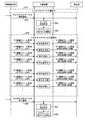
図3は、実施例1にかかる無線通信方法の手順を示すフローチャートである。図3に示すように、中継装置2は、マルチキャストサービス部4によりマルチキャストサービスが開始されると(ステップS1)、無線基地局A1から受信した信号がマルチキャスト通信の信号であるか否かを判断する(ステップS2)。無線基地局A1からの受信信号がマルチキャスト通信の信号である場合(ステップS2:Yes)、中継装置2は、非再生処理部12により受信信号をそのまま用いて非再生信号を生成する。そして、中継装置2は、送信部15により非再生信号を送信する(非再生処理、ステップS3)。無線基地局A1からの受信信号がユニキャスト通信の信号である場合(ステップS2:No)、中継装置2は、再生処理部14により受信信号から元のデータを再生し、そのデータから再生信号を生成する。そして、中継装置2は、送信部15により再生信号を送信する(再生処理、ステップS4)。次いで、中継装置2は、マルチキャストサービスの終了であるか否かを判断する(ステップS5)。マルチキャストサービスが継続されている場合(ステップS5:No)、ステップS2に戻る。マルチキャストサービスの終了であれば、中継装置2は、一連の処理を終了し、例えばユニキャスト通信に戻る。 FIG. 3 is a flowchart of a procedure of the wireless communication method according to the first embodiment. As shown in FIG. 3, when the
実施例1によれば、中継装置2が、無線基地局A1からマルチキャスト通信の信号を受信すると、非再生処理を行って中継するので、中継装置2が中継することによる遅延量を抑制することができる。例えば、移動局3は、図1に示す例のように中継装置2の通信可能領域7と無線基地局B5の通信可能領域8との境界付近にいる場合、中継装置2を介して無線基地局A1からのマルチキャスト通信の信号と、直接、無線基地局B5からのマルチキャスト通信の信号とを受信する。その場合、無線基地局A1からのマルチキャスト通信の信号は、中継装置2で中継される分、無線基地局B5からのマルチキャスト通信の信号よりも遅れて移動局3により受信される。しかし、実施例1によれば、移動局3において無線基地局A1からのマルチキャスト通信の信号と、無線基地局B5からのマルチキャスト通信の信号との同期が取れる程度に、中継装置2での遅延量が抑制されることにより、移動局3は、複数の無線基地局からマルチキャスト通信で送信された信号を正確に受信することができる。また、ユニキャスト通信の場合には、中継装置2が再生処理を行って中継するので、例えば波形が鈍った受信信号に対して中継装置2で波形成形を行って送信するなど、再生処理を行う場合のメリットを享受することができる。 According to the first embodiment, when the
(実施例2)
実施例2では、無線通信システムの一例として、マルチキャスト通信とユニキャスト通信の両方を行う移動体通信システムが挙げられる。例えば、3rd Generation Partnership Project(3GPP、第3世代移動体通信システムの標準化プロジェクト)、Long Term Evolution(LTE)またはLTE−Advancedなどのシステムが挙げられる。LTEは、3GPPにおいて標準化されている移動体通信システムの仕様である。LTE−Advancedは、LTEを発展させたシステムである。マルチキャストサービスの一例として、Earthquake and Tsunami Warning System(ETWS)やEnhanced−Multimedia Broadcast Multicast Services(E−MBMS)などが挙げられる。E−MBMSにおいては、MBMS Single Frequency Network(MBSFN)が想定されている。MBSFNは、単一周波数ネットワークによるモバイルマルチキャストサービスである。また、マルチキャストサービス部の一例として、Mobility Management Entity/Serving Gateway(MME/S−GW、移動通信管理装置/サービングゲートウェイ)やMBMS Gateway/MICE(MBMS GW/MICE)が挙げられる。(Example 2)
In the second embodiment, a mobile communication system that performs both multicast communication and unicast communication is an example of a wireless communication system. For example, a system such as 3rd Generation Partnership Project (3GPP, third generation mobile communication system standardization project), Long Term Evolution (LTE), or LTE-Advanced is available. LTE is a specification of a mobile communication system standardized in 3GPP. LTE-Advanced is a system developed from LTE. Examples of multicast services include Earthquake and Tsunami Warming System (ETWS), Enhanced-Multimedia Broadcast Multiservices (E-MBMS), and the like. In E-MBMS, MBMS Single Frequency Network (MBSFN) is assumed. MBSFN is a mobile multicast service by a single frequency network. Examples of the multicast service unit include Mobility Management Entity / Serving Gateway (MME / S-GW, mobile communication management device / serving gateway) and MBMS Gateway / MICE (MBMS GW / MICE).
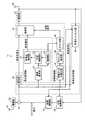
図4は、実施例2にかかる中継装置の構成を示すブロック図である。図4に示すように、中継装置21は、受信アンテナ22、受信用の増幅部23、結合部24、振幅制御部25、位相制御部A26、送信用の増幅部27および送信アンテナ28を備えている。受信アンテナ22は、無線基地局からの無線信号を受信する。受信用の増幅部23は、受信アンテナ22で受信した信号を増幅する。送信用の増幅部27は、送信対象の信号を増幅する。送信アンテナ28は、送信用の増幅部27の出力信号を送信する。位相制御部A26は、送信用の増幅部27の出力信号の位相を制御する。振幅制御部25は、位相制御部A26の出力信号の振幅を制御する。結合部24は、受信用の増幅部23の出力信号と、振幅制御部25から出力されるフィードバック信号とを結合した信号を出力する。受信アンテナ22および受信用の増幅部23は、受信部として動作する。送信用の増幅部27および送信アンテナ28は、送信部として動作する。 FIG. 4 is a block diagram of the configuration of the relay device according to the second embodiment. As illustrated in FIG. 4, the relay device 21 includes a
また、中継装置21は、遅延部29および干渉キャンセル部30を備えている。遅延部29は、結合部24の出力信号を遅延させた信号を非再生信号として出力する。干渉キャンセル部30は、結合部24の出力信号と送信用の増幅部27の出力信号とに基づいて制御信号Aを出力する。位相制御部A26および振幅制御部25は、非再生処理時に、それぞれ制御信号Aに基づいて位相および振幅を制御する。それによって、非再生処理時に、送信アンテナ28から送信される信号を受信アンテナ22で受信することによる干渉が抑制される。遅延部29および干渉キャンセル部30は、非再生処理部として動作する。 In addition, the relay device 21 includes a
また、中継装置21は、復調・復号部31、符号化・変調部32および制御部A33を備えている。復調・復号部31は、結合部24の出力信号を復調し、復号して元のデータを生成する。符号化・変調部32は、復調・復号部31で生成される元のデータを符号化し、変調して再生信号を生成する。制御部A33は、符号化・変調部32による再生信号の生成動作を制御する。制御部A33は、復調・復号部31で生成される元のデータに基づいてマルチキャストサービスの有無を判断し、後述するカウンタ部36へマルチキャストサービスの有無を通知する。制御部A33は、復調・復号部31の出力信号と符号化・変調部32の出力信号とに基づいて制御信号Bを出力する。位相制御部A26および振幅制御部25は、再生処理時に、それぞれ制御信号Bに基づいて位相および振幅を制御する。それによって、再生処理時に、送信アンテナ28から送信される信号を受信アンテナ22で受信することによる干渉が抑制される。復調・復号部31、符号化・変調部32および制御部A33は、再生処理部として動作する。 The relay device 21 includes a demodulation /
また、中継装置21は、同期チャネル検出部34、タイミング検出部35、カウンタ部36および選択部37を備えている。同期チャネル検出部34は、結合部24の出力信号から同期チャネルを検出し、無線フレームの同期を確立する。タイミング検出部35は、無線フレームのタイミングを検出し、タイミング信号を出力する。カウンタ部36は、タイミング検出部35から出力されるタイミング信号に基づいて無線フレームのサブフレームをカウントする。カウンタ部36は、サブフレームのカウント値と制御部A33からの通知とに基づいて、マルチキャスト通信のサブフレームとユニキャスト通信のサブフレームとの切り替え位置を判定し、切替信号を生成する。選択部37は、切替信号に基づいて、遅延部29から出力される非再生信号と符号化・変調部32から出力される再生信号とのいずれか一方を選択し、送信対象の信号として送信用の増幅部27へ出力する。同期チャネル検出部34、タイミング検出部35、カウンタ部36および選択部37は、切替制御部として動作する。 The relay device 21 includes a synchronization
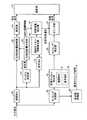
図5は、実施例2にかかる中継装置の要部の構成を示すブロック図である。図5には、再生処理部および切替制御部の一例が示されている。図5に示すように、中継装置21は、再生処理部として、復調部A41、復号部A42、符号化部A43、変調部44、制御部B45、制御チャネル情報抽出部46および切替情報抽出部47を備えている。復調部A41は、入力信号(結合部24の出力信号)を復調する。復号部A42は、復調部A41の出力信号を復号して元のデータを生成する。復調部A41および復号部A42は、復調・復号部31として動作する。符号化部A43は、復調・復号部31で生成される元のデータを符号化する。変調部44は、符号化部A43の出力信号を変調して再生信号を生成する。符号化部A43および変調部44は、符号化・変調部32として動作する。 FIG. 5 is a block diagram of a configuration of a main part of the relay device according to the second embodiment. FIG. 5 shows an example of the reproduction processing unit and the switching control unit. As shown in FIG. 5, the relay device 21 has a demodulation unit A41, a decoding unit A42, an encoding unit A43, a
制御部B45は、復調部A41の出力信号と符号化部A43の出力信号とに基づいて制御信号Bを生成する。制御チャネル情報抽出部46は、復号部A42で生成される元のデータに基づいて制御チャネル情報を抽出する。切替情報抽出部47は、制御チャネル情報に基づいて、マルチキャストサービスの運用開始という情報とマルチキャストサービスの運用終了という情報とを抽出する。切替情報抽出部47は、マルチキャストサービスの運用開始という情報を抽出すると、マルチキャストサービスの運用終了という情報を抽出するまで、カウンタ部36へ切替有無通知として切替有という通知をする。マルチキャストサービスが運用されていない期間では、切替情報抽出部47は、カウンタ部36へ切替有無通知として切替無という通知をする。制御部B45、制御チャネル情報抽出部46および切替情報抽出部47は、制御部A33として動作する。 The control unit B45 generates the control signal B based on the output signal of the demodulation unit A41 and the output signal of the encoding unit A43. The control channel
中継装置21は、切替制御部として、タイミング同期部48、同期チャネル抽出部49、タイミング検出部35、カウンタ部36、選択部37および周波数制御部50を備えている。タイミング同期部48は、入力信号(結合部24の出力信号)に基づいて同期をとる。同期チャネル抽出部49は、復調部B51および復号部B52を備えており、復調および復号を行って同期チャネルを抽出する。タイミング検出部35、カウンタ部36および選択部37については、図4を参照しながら説明した通りである。ただし、カウンタ部36においては、制御部A33からの通知として、切替情報抽出部47から切替有無通知(切替有または切替無)が通知される。周波数制御部50は、タイミング同期部48の出力信号に基づいて基準タイミング信号を生成し、基準タイミング信号を中継装置内の各部へ供給する。タイミング同期部48、同期チャネル抽出部49および周波数制御部50は、同期チャネル検出部34として動作する。 The relay device 21 includes a
図6は、実施例2における無線通信フレームの構成を示す模式図である。図6に示すように、例えばLTEにおいては、無線フレームは、例えば#0から#19までの20個のスロット61を含む。サブフレーム62は、例えば2個のスロット61を含む。例えば、サブフレーム#0は、スロット#0とスロット#1を含む。サブフレーム#1は、スロット#2とスロット#3(図示省略)を含む。途中を省略するが、サブフレーム#9は、スロット#18とスロット#19を含む。つまり、無線フレームには、例えば#0から#9までの10個のサブフレーム62が含まれる。例えばLTEにおいては、サブフレーム#1とサブフレーム#9は、マルチキャスト通信に割り当てられる。#0と#2から#8までのサブフレームは、ユニキャスト通信に割り当てられる。従って、カウンタ部36でサブフレームをカウントすることによって、マルチキャスト通信のサブフレーム(#1、#9)とユニキャスト通信のサブフレーム(#0、#2〜#8)との切り替え位置を判定し、再生処理と非再生処理との切り替えを行うことができる。 FIG. 6 is a schematic diagram illustrating a configuration of a wireless communication frame according to the second embodiment. As illustrated in FIG. 6, for example, in LTE, a radio frame includes 20
図7および図8は、実施例2にかかる無線通信方法の手順を示すフローチャートである。図7に示すように、ユニキャストサービスの運用中に、中継装置21が無線基地局からマルチキャストサービスの開始通知を受信すると(ステップS11)、中継装置21は、タイミング同期部48および同期チャネル抽出部49により無線フレームのタイミングを検出する(ステップS12)。次いで、中継装置21は、検出したタイミングが無線フレームの先頭位置であるか否かを判定する(ステップS13)。無線フレームの先頭位置でなければ(ステップS13:No)、中継装置21は、無線フレームの先頭位置を検出するまで待機する。中継装置21は、無線フレームの先頭位置を検出したら(ステップS13:Yes)、無線フレーム用のカウンタの動作を開始する(ステップS14)。無線フレーム用のカウンタは、タイミング検出部35に備えられている。次いで、中継装置21は、サブフレーム用のカウンタの動作を開始する(ステップS15)。サブフレーム用のカウンタは、カウンタ部36に備えられている。 7 and 8 are flowcharts illustrating the procedure of the wireless communication method according to the second embodiment. As shown in FIG. 7, when the relay device 21 receives a multicast service start notification from the radio base station during the operation of the unicast service (step S11), the relay device 21 includes a
次いで、図8に示すように、中継装置21は、サブフレーム用のカウンタの値が1であるか、または9であるかを判定する(ステップS16)。サブフレーム用のカウンタの値が1または9である場合(ステップS16:Yes)、中継装置21は、選択部37により非再生処理側を選択し、選択部37から非再生信号を出力する(ステップS17)。サブフレーム用のカウンタの値が0または2〜8のいずれかである場合(ステップS16:No)、中継装置21は、選択部37による切り替えを行わずに、サブフレーム用のカウンタがカウントアップされたか否かを判定する(ステップS18)。サブフレーム用のカウンタがカウントアップされていなければ(ステップS18:No)、中継装置21は、サブフレーム用のカウンタがカウントアップされるのを待つ。サブフレーム用のカウンタがカウントアップされていれば(ステップS18:Yes)、中継装置21は、サブフレーム用のカウンタの値が1または9でないかを判定する(ステップS19)。サブフレーム用のカウンタの値が1または9でない場合(ステップS19:Yes)、中継装置21は、選択部37により再生処理側を選択し、選択部37から再生信号を出力する(ステップS20)。サブフレーム用のカウンタの値が1または9である場合(ステップS19:No)、中継装置21は、選択部37による切り替えを行わずに、無線基地局からマルチキャストサービスの終了通知を受信したか否かを判定する(ステップS21)。マルチキャストサービスの終了通知を受信していない場合(ステップS21:No)、ステップS16へ戻る。マルチキャストサービスの終了通知を受信している場合(ステップS21:Yes)、中継装置21は、選択部37により非再生処理側を選択し、選択部37から非再生信号を出力する(ステップS22)。そして、一連の処理が終了し、ユニキャストサービスの運用状態に戻る。 Next, as illustrated in FIG. 8, the relay device 21 determines whether the value of the subframe counter is 1 or 9 (step S16). If the counter value for the subframe is 1 or 9 (step S16: Yes), the relay device 21 selects the non-reproduction processing side by the
図9は、実施例2にかかる無線通信システムにおける無線通信手順を示すシーケンス図である。図9に示すように、ユニキャストサービスの運用中(ステップS31)、中継装置21は、無線基地局からマルチキャストサービスの開始通知を受信すると(ステップS32)、ユニキャストサービスからマルチキャストサービスへの切り替えを判定し(ステップS33)、サブフレーム用のカウンタの動作を開始する(ステップS34)。マルチキャストサービスの運用中(ステップS35)、中継装置21が無線基地局から例えば#0または#2〜#8のいずれかのサブフレームを受信すると、中継装置21は再生処理で中継して再生信号を移動局へ送信する。マルチキャストサービスの運用中(ステップS35)、中継装置21が無線基地局から例えば#1または#9のサブフレームを受信すると、中継装置21は非再生処理で中継して非再生信号を移動局へ送信する。中継装置21は、無線基地局からマルチキャストサービスの終了通知を受信すると(ステップS36)、マルチキャストサービスからユニキャストサービスへの切り替えを判定し(ステップS37)、サブフレーム用のカウンタの動作を停止する(ステップS38)。ユニキャストサービスとマルチキャストサービスとの切り替えの判定は、切替情報抽出部47により行われる。 FIG. 9 is a sequence diagram of a wireless communication procedure in the wireless communication system according to the second embodiment. As shown in FIG. 9, during operation of the unicast service (step S31), when the relay apparatus 21 receives a multicast service start notification from the radio base station (step S32), the relay apparatus 21 switches from the unicast service to the multicast service. The determination is made (step S33), and the operation of the subframe counter is started (step S34). During operation of the multicast service (step S35), when the relay device 21 receives, for example, any subframe of # 0 or # 2 to # 8 from the radio base station, the relay device 21 relays the playback signal by a playback process. Send to the mobile station. During operation of the multicast service (step S35), when the relay device 21 receives, for example, a # 1 or # 9 subframe from the radio base station, the relay device 21 relays by non-reproduction processing and transmits a non-reproduction signal to the mobile station. To do. When receiving the multicast service end notification from the radio base station (step S36), the relay device 21 determines switching from the multicast service to the unicast service (step S37), and stops the operation of the subframe counter (step S37). Step S38). The switching
実施例2によれば、実施例1と同様の効果が得られる。また、実施例2によれば、マルチキャストサービスの運用時に、隣接する複数の無線基地局から送信されたマルチキャスト通信の無線信号が移動局に到達するまでの時間差が少なくなる。従って、移動局は、隣接する無線基地局間を移動しても、違和感なくマルチキャストサービスを受け続けることができる。 According to the second embodiment, the same effect as the first embodiment can be obtained. Further, according to the second embodiment, during the operation of the multicast service, a time difference until a multicast communication radio signal transmitted from a plurality of adjacent radio base stations reaches the mobile station is reduced. Therefore, even if the mobile station moves between adjacent radio base stations, the mobile station can continue to receive the multicast service without a sense of incongruity.
(実施例3)
図10は、実施例3にかかる中継装置の構成を示すブロック図である。図10に示すように、中継装置71は、実施例2の構成において、位相制御部A26とは別に位相制御部B72を設け、位相制御部A26および振幅制御部25の代わりに、再生処理時の位相制御を位相制御部B72で行うようにしたものである。非再生処理時の位相制御および振幅制御については、実施例2と同様に位相制御部A26および振幅制御部25が行う。(Example 3)
FIG. 10 is a block diagram of the configuration of the relay device according to the third embodiment. As illustrated in FIG. 10, the
図11は、実施例3にかかる中継装置の要部の構成を示すブロック図である。図11には、再生処理部および切替制御部の一例が示されている。図11に示すように、中継装置71は、実施例2の構成において、符号化部A43および制御部B45の代わりに、チャネル推定部81、位相回転量制御部82および位相回転量決定部83を備えている。チャネル推定部81は、復調部A41の出力信号に基づいて、無線基地局との間の伝送路についてチャネル推定を行う。位相回転量決定部83は、チャネル推定部81から出力されるチャネル推定値に基づいて位相回転量を決定する。位相回転量制御部82は、位相回転量決定部83により決定される位相回転量に基づいて、復調部A41の出力信号に対して位相回転量を制御する。位相回転量制御部82の出力信号は、変調部44へ送られる。チャネル推定部81、位相回転量制御部82および位相回転量決定部83は、位相制御部B72として動作する。実施例3において、その他の構成および動作は実施例2と同様である。実施例3によれば、実施例2と同様の効果が得られる。 FIG. 11 is a block diagram of a configuration of main parts of the relay device according to the third embodiment. FIG. 11 shows an example of the reproduction processing unit and the switching control unit. As illustrated in FIG. 11, the
(実施例4)
図12は、実施例4にかかる中継装置の構成を示すブロック図である。図12に示すように、実施例4の中継装置は、実施例3の構成において、Multiple Input Multiple Output(MIMO、マイモ)モードで運用中に送受信アンテナ間の相関に基づいて、再生処理と非再生処理との切り替えを行う。位相回転量決定部83は、切替情報抽出部47にMIMO相関情報を渡す。切替情報抽出部47は、マルチキャストサービスの運用中に、MIMO相関情報に基づいて切替有無通知を出力する。切替情報抽出部47は、送受信アンテナ間の相関値が閾値以上である場合、チャネル推定部81、位相回転量制御部82および位相回転量決定部83による位相回転量の制御処理(再生処理)に切り替える。切替情報抽出部47は、送受信アンテナ間の相関値よりも低い場合、非再生処理に切り替える。閾値は、通信事業者によって予め設定されている。MIMOモード以外、例えばSingle Input Multiple Output(SIMO)モードで運用中の場合には、非再生処理が選択される。Example 4
FIG. 12 is a block diagram of the configuration of the relay device according to the fourth embodiment. As illustrated in FIG. 12, the relay apparatus according to the fourth embodiment is configured to perform the reproduction process and the non-reproduction based on the correlation between the transmission and reception antennas in the multiple input multiple output (MIMO) mode in the configuration of the third embodiment. Switch to processing. The phase rotation
図13は、実施例4にかかる無線通信方法の手順を示すフローチャートである。図13に示すように、マルチキャストサービスの運用中に、中継装置は、制御チャネルを受信し(ステップS41)、サービス内容を確認する(ステップS42)。そして、中継装置は、MIMOモードであるか否かを判定する(ステップS43)。MIMOモードである場合(ステップS43:Yes)、中継装置は、選択部37により再生処理側を選択し、選択部37から再生信号を出力する(ステップS44)。次いで、中継装置は、チャネル推定値に基づいて送受信アンテナ間の相関値を演算する(ステップS45)。次いで、中継装置は、送受信アンテナ間の相関値が閾値以上であるか否かを判定する(ステップS46)。送受信アンテナ間の相関値が閾値以上である場合(ステップS46:Yes)、中継装置は、位相回転量決定部83により位相回転量を演算する(ステップS47)。そして、中継装置は、送受信アンテナ間の相関値が改善されるか否かを判定し(ステップS49)、改善されるまで位相回転量の演算を行う(ステップS49:No、ステップS47)。送受信アンテナ間の相関値が改善される場合(ステップS49:Yes)、ステップS41に戻る。一方、MIMOモードでない場合(ステップS43:No)または送受信アンテナ間の相関値が閾値よりも低い場合(ステップS46:No)、中継装置は、選択部37により非再生処理側を選択し、選択部37から非再生信号を出力する(ステップS48)。そして、ステップS41に戻る。実施例4において、その他の構成および動作は実施例3と同様である。 FIG. 13 is a flowchart of a procedure of the wireless communication method according to the fourth embodiment. As shown in FIG. 13, during the operation of the multicast service, the relay device receives the control channel (step S41) and confirms the service content (step S42). Then, the relay device determines whether or not it is in the MIMO mode (step S43). When it is in the MIMO mode (step S43: Yes), the relay device selects the reproduction processing side by the
実施例4によれば、実施例2と同様の効果が得られる。また、アンテナ相関に基づいて再生処理と非再生処理とを切り替えることにより、中継装置内の位相回転等の演算処理量を削減することができる。また、演算処理量が削減されることによって、中継装置の省電力化を図ることができる。 According to the fourth embodiment, the same effect as the second embodiment can be obtained. Further, by switching between reproduction processing and non-reproduction processing based on the antenna correlation, it is possible to reduce the amount of calculation processing such as phase rotation in the relay device. In addition, by reducing the amount of calculation processing, it is possible to save power in the relay device.
上述した実施の形態に関し、さらに以下の付記を開示する。 The following additional notes are disclosed with respect to the embodiment described above.
(付記1)無線信号を受信して受信信号を出力する受信部と、
前記受信信号から元のデータを再生し、該データから再生信号を生成する再生処理部と、
前記受信信号を用いて非再生信号を生成する非再生処理部と、
前記受信信号がマルチキャスト通信の信号であるときに前記非再生信号を選択して出力し、前記受信信号がユニキャスト通信の信号であるときに前記再生信号を選択して出力する切替制御部と、
前記切替制御部の出力信号を送信信号として送信する送信部と、
を備えることを特徴とする中継装置。(Appendix 1) A receiving unit that receives a radio signal and outputs a received signal;
A reproduction processing unit for reproducing original data from the received signal and generating a reproduction signal from the data;
A non-reproduction processing unit that generates a non-reproduction signal using the received signal;
A switching control unit for selecting and outputting the non-reproduction signal when the received signal is a signal for multicast communication, and for selecting and outputting the reproduction signal when the reception signal is a signal for unicast communication;
A transmission unit that transmits an output signal of the switching control unit as a transmission signal;
A relay device comprising:
(付記2)前記切替制御部は、前記受信信号を復調した制御チャネル情報に基づいて前記非再生信号の選択と前記再生信号の選択とを切り替えることを特徴とする付記1に記載の中継装置。(Supplementary note 2) The relay apparatus according to
(付記3)前記切替制御部は、前記受信信号の無線フレームのサブフレーム単位で前記非再生信号の選択と前記再生信号の選択とを切り替えることを特徴とする付記1に記載の中継装置。(Supplementary note 3) The relay apparatus according to
(付記4)前記切替制御部は、同期チャネルから抽出したフレームタイミングに基づいてサブフレームをカウントすることによって、マルチキャスト通信のサブフレームを特定することを特徴とする付記3に記載の中継装置。(Additional remark 4) The said switching control part specifies the subframe of multicast communication by counting a subframe based on the frame timing extracted from the synchronous channel, The relay apparatus of
(付記5)前記切替制御部は、無線基地局との間の伝送路のチャネル情報に基づいて前記非再生信号の選択と前記再生信号の選択とを切り替えることを特徴とする付記1に記載の中継装置。(Additional remark 5) The said switching control part switches the selection of the said non-reproduction | regeneration signal and the selection of the said reproduction | regeneration signal based on the channel information of the transmission path between radio base stations. Relay device.
(付記6)マルチキャストサービスを提供するマルチキャストサービス部と、
ユニキャスト通信の無線信号または前記マルチキャストサービスによるマルチキャスト通信の無線信号を送信する無線基地局と、
前記無線基地局の送信信号を受信し、該受信信号がユニキャスト通信の信号であるときに該受信信号から元のデータを再生し、該データから再生信号を生成して送信し、また、該受信信号がマルチキャスト通信の信号であるときに該受信信号をそのまま用いて非再生信号を生成して送信する中継装置と、
前記中継装置の送信信号を受信する移動局と、
を備えることを特徴とする無線通信システム。(Appendix 6) A multicast service section that provides a multicast service;
A radio base station for transmitting a radio signal for unicast communication or a radio signal for multicast communication by the multicast service;
Receiving a transmission signal of the radio base station, reproducing the original data from the received signal when the received signal is a unicast communication signal, generating and transmitting a reproduction signal from the data; and A relay device that generates and transmits a non-regenerative signal using the received signal as it is when the received signal is a multicast communication signal;
A mobile station that receives the transmission signal of the relay device;
A wireless communication system comprising:
(付記7)前記中継装置は、無線フレームのサブフレーム単位で前記非再生信号の送信と前記再生信号の送信とを切り替えることを特徴とする付記6に記載の無線通信システム。(Supplementary note 7) The radio communication system according to
(付記8)前記中継装置は、前記無線基地局との間の伝送路のチャネル情報に基づいて前記非再生信号の送信と前記再生信号の送信とを切り替えることを特徴とする付記6に記載の無線通信システム。(Additional remark 8) The said relay apparatus switches transmission of the said non-reproduction | regeneration signal and transmission of the said reproduction | regeneration signal based on the channel information of the transmission path between the said radio base stations, The
(付記9)マルチキャストサービスの提供時に、受信信号がマルチキャスト通信の信号であるか否かを判断するステップと、
前記受信信号がマルチキャスト通信の信号である場合に前記受信信号をそのまま用いて非再生信号を生成して送信するステップと、
前記受信信号がユニキャスト通信の信号である場合に前記受信信号から元のデータを再生し、該データから再生信号を生成して送信するステップと、
を含むことを特徴とする無線通信方法。(Supplementary Note 9) When providing a multicast service, determining whether a received signal is a signal for multicast communication;
When the received signal is a multicast communication signal, generating and transmitting a non-regenerated signal using the received signal as it is;
Reproducing the original data from the received signal when the received signal is a unicast communication signal, generating a reproduced signal from the data, and transmitting the data;
A wireless communication method comprising:
(付記10)前記受信信号の無線フレームのサブフレーム単位で前記非再生信号の送信と前記再生信号の送信とを切り替えることを特徴とする付記9に記載の無線通信方法。(Supplementary note 10) The radio communication method according to
(付記11)同期チャネルから抽出したフレームタイミングに基づいてサブフレームをカウントすることによって、マルチキャスト通信のサブフレームを特定することを特徴とする付記10に記載の無線通信方法。(Additional remark 11) The radio | wireless communication method of Additional remark 10 characterized by specifying a subframe of multicast communication by counting a subframe based on the frame timing extracted from the synchronous channel.
(付記12)無線基地局との間の伝送路のチャネル情報に基づいて前記非再生信号の送信と前記再生信号の送信とを切り替えることを特徴とする付記9に記載の無線通信方法。(Supplementary note 12) The radio communication method according to
1 無線基地局
2,21,71 中継装置
3 移動局
4 マルチキャストサービス部
11 受信部
12 非再生処理部
13 切替制御部
14 再生処理部
15 送信部DESCRIPTION OF
Claims (10)
Translated fromJapanese前記受信信号から元のデータを再生し、該データから再生信号を生成する再生処理部と、
前記受信信号を用いて非再生信号を生成する非再生処理部と、
前記受信信号がマルチキャスト通信の信号であるときに前記非再生信号を選択して出力し、前記受信信号がユニキャスト通信の信号であるときに前記再生信号を選択して出力する切替制御部と、
前記切替制御部の出力信号を送信信号として送信する送信部と、
を備えることを特徴とする中継装置。A receiver that receives a radio signal and outputs a received signal;
A reproduction processing unit for reproducing original data from the received signal and generating a reproduction signal from the data;
A non-reproduction processing unit that generates a non-reproduction signal using the received signal;
A switching control unit for selecting and outputting the non-reproduction signal when the received signal is a signal for multicast communication, and for selecting and outputting the reproduction signal when the reception signal is a signal for unicast communication;
A transmission unit that transmits an output signal of the switching control unit as a transmission signal;
A relay device comprising:
ユニキャスト通信の無線信号または前記マルチキャストサービスによるマルチキャスト通信の無線信号を送信する無線基地局と、
前記無線基地局の送信信号を受信し、該受信信号がユニキャスト通信の信号であるときに該受信信号から元のデータを再生し、該データから再生信号を生成して送信し、また、該受信信号がマルチキャスト通信の信号であるときに該受信信号をそのまま用いて非再生信号を生成して送信する中継装置と、
前記中継装置の送信信号を受信する移動局と、
を備えることを特徴とする無線通信システム。A multicast service section that provides a multicast service;
A radio base station for transmitting a radio signal for unicast communication or a radio signal for multicast communication by the multicast service;
Receiving a transmission signal of the radio base station, reproducing the original data from the received signal when the received signal is a unicast communication signal, generating and transmitting a reproduction signal from the data; and A relay device that generates and transmits a non-regenerative signal using the received signal as it is when the received signal is a multicast communication signal;
A mobile station that receives the transmission signal of the relay device;
A wireless communication system comprising:
前記受信信号がマルチキャスト通信の信号である場合に前記受信信号をそのまま用いて非再生信号を生成して送信するステップと、
前記受信信号がユニキャスト通信の信号である場合に前記受信信号から元のデータを再生し、該データから再生信号を生成して送信するステップと、
を含むことを特徴とする無線通信方法。Determining whether the received signal is a multicast communication signal when providing a multicast service; and
When the received signal is a multicast communication signal, generating and transmitting a non-regenerated signal using the received signal as it is;
Reproducing the original data from the received signal when the received signal is a unicast communication signal, generating a reproduced signal from the data, and transmitting the data;
A wireless communication method comprising:
Applications Claiming Priority (1)
| Application Number | Priority Date | Filing Date | Title |
|---|---|---|---|
| PCT/JP2009/059431WO2010134195A1 (en) | 2009-05-22 | 2009-05-22 | Relay device, wireless communication system, and wireless communication method |
Publications (2)
| Publication Number | Publication Date |
|---|---|
| JPWO2010134195A1 JPWO2010134195A1 (en) | 2012-11-08 |
| JP5327320B2true JP5327320B2 (en) | 2013-10-30 |
Family
ID=43125891
Family Applications (1)
| Application Number | Title | Priority Date | Filing Date |
|---|---|---|---|
| JP2011514266AExpired - Fee RelatedJP5327320B2 (en) | 2009-05-22 | 2009-05-22 | Relay device, radio communication system, and radio communication method |
Country Status (3)
| Country | Link |
|---|---|
| US (1) | US8441978B2 (en) |
| JP (1) | JP5327320B2 (en) |
| WO (1) | WO2010134195A1 (en) |
Families Citing this family (7)
| Publication number | Priority date | Publication date | Assignee | Title |
|---|---|---|---|---|
| BRPI0924673A2 (en)* | 2009-06-22 | 2016-01-26 | Alcatel Lucent | method and device for processing component carriers to be aggregated for transmission |
| EP2730045B1 (en) | 2011-07-08 | 2016-06-29 | Telefonaktiebolaget LM Ericsson (publ) | Relaying multicast data in a wireless network |
| EP2759073B1 (en) | 2011-09-20 | 2015-12-09 | Telefonaktiebolaget L M Ericsson (PUBL) | Relaying unicast and multicast data in a wireless network |
| US9820259B2 (en)* | 2012-05-04 | 2017-11-14 | Qualcomm Incorporated | Smooth transition between multimedia broadcast multicast service (MBMS) and unicast service by demand |
| GB2503923A (en)* | 2012-07-12 | 2014-01-15 | Nec Corp | Coordinated multipoint transmissions to a relay node |
| JP7645361B2 (en)* | 2021-03-31 | 2025-03-13 | 株式会社Nttドコモ | Wireless relay device and wireless relay method |
| US20240056163A1 (en)* | 2022-08-10 | 2024-02-15 | Toyota Jidosha Kabushiki Kaisha | Communication system, method, relay station, and control device |
Citations (2)
| Publication number | Priority date | Publication date | Assignee | Title |
|---|---|---|---|---|
| JP2007500482A (en)* | 2003-05-28 | 2007-01-11 | テレフオンアクチーボラゲット エル エム エリクソン(パブル) | Method and system for a wireless communication network utilizing relay |
| JP2008541607A (en)* | 2005-05-11 | 2008-11-20 | テレフオンアクチーボラゲット エル エム エリクソン(パブル) | Multi-carrier scheduling |
Family Cites Families (7)
| Publication number | Priority date | Publication date | Assignee | Title |
|---|---|---|---|---|
| JPH09284195A (en) | 1996-04-19 | 1997-10-31 | Kokusai Electric Co Ltd | Wireless relay booster |
| JP3603714B2 (en) | 2000-01-06 | 2004-12-22 | Kddi株式会社 | Repeater device for code division multiple access system |
| JP3670254B2 (en) | 2002-07-05 | 2005-07-13 | Kddi株式会社 | Repeater device and control program for repeater device |
| JP4394474B2 (en) | 2004-02-16 | 2010-01-06 | 株式会社エヌ・ティ・ティ・ドコモ | Wireless relay system, wireless relay device, and wireless relay method |
| US20080045145A1 (en)* | 2006-08-17 | 2008-02-21 | Fujitsu Limited | Radio Relay Communication Method, Radio Base Station, and Radio Relay Station in Radio Communication System |
| KR100974271B1 (en)* | 2008-05-15 | 2010-08-06 | 성균관대학교산학협력단 | Multicast and broadcast service relay system and relay method |
| KR101527975B1 (en)* | 2009-02-11 | 2015-06-15 | 엘지전자 주식회사 | Method for relaying data in wireless communication system |
- 2009
- 2009-05-22JPJP2011514266Apatent/JP5327320B2/ennot_activeExpired - Fee Related
- 2009-05-22WOPCT/JP2009/059431patent/WO2010134195A1/ennot_activeCeased
- 2011
- 2011-09-20USUS13/237,484patent/US8441978B2/ennot_activeExpired - Fee Related
Patent Citations (2)
| Publication number | Priority date | Publication date | Assignee | Title |
|---|---|---|---|---|
| JP2007500482A (en)* | 2003-05-28 | 2007-01-11 | テレフオンアクチーボラゲット エル エム エリクソン(パブル) | Method and system for a wireless communication network utilizing relay |
| JP2008541607A (en)* | 2005-05-11 | 2008-11-20 | テレフオンアクチーボラゲット エル エム エリクソン(パブル) | Multi-carrier scheduling |
Also Published As
| Publication number | Publication date |
|---|---|
| JPWO2010134195A1 (en) | 2012-11-08 |
| US20120020273A1 (en) | 2012-01-26 |
| WO2010134195A1 (en) | 2010-11-25 |
| US8441978B2 (en) | 2013-05-14 |
Similar Documents
| Publication | Publication Date | Title |
|---|---|---|
| JP5327320B2 (en) | Relay device, radio communication system, and radio communication method | |
| JP5125988B2 (en) | Wireless relay device | |
| KR101385695B1 (en) | Mobile communication system, relay station apparatus, base station apparatus, radio relay method, and computer readable medium | |
| CA2734483A1 (en) | Method and apparatus for determining an end of a subframe in a tdd system | |
| JP2022548588A (en) | Repeater system for use with 5G new radio base stations using time division duplexing | |
| CN101588339B (en) | Method for reducing wireless relaying redundant forwarding on the basis of iterated code | |
| JP5553107B2 (en) | RELAY DEVICE, RELAY DEVICE CONTROL METHOD, AND RADIO COMMUNICATION SYSTEM | |
| KR20080043031A (en) | Method and apparatus for relay service in mobile communication system with orthogonal frequency division multiplexing | |
| KR101400715B1 (en) | Apparatus and method for communication using cooperative tranmission and network coding transmission | |
| US20080137561A1 (en) | Rf repeater used for time division duplexing and method thereof | |
| US8447229B2 (en) | Radio communication system, base station apparatus and relay station apparatus | |
| JP4933416B2 (en) | Wireless communication method, wireless communication system, and relay station | |
| KR100965688B1 (en) | Ranging method and apparatus in communication system including relay station and system therefor | |
| JP5036681B2 (en) | Radio relay system, radio relay method, relay station, and transmitting / receiving station | |
| Morosi et al. | Cooperative delay diversity in hybrid satellite/terrestrial DVB-SH system | |
| JP4419731B2 (en) | Wireless communication apparatus and wireless communication method | |
| KR101412180B1 (en) | Terminal for repeating and method of repeating through the terminal in MBS network | |
| JPWO2012105057A1 (en) | Radio relay apparatus, mobile station, radio communication system, and interference measurement method | |
| CN101510800A (en) | Double-repeat signal transmission method based on interference cancellation | |
| KR101586716B1 (en) | Communication Method and Apparatus using slot based channel | |
| JP5395683B2 (en) | Relay device and relay method | |
| WO2007088633A1 (en) | Wireless communication system, mobile station apparatus and relay station apparatus | |
| KR101907361B1 (en) | An adaptive-Incremental Decode-and-Forward Relaying Scheme for Cooperative Non-Orthogonal Multiple Access Systems | |
| KR101922846B1 (en) | A Coordinated Direct and Relay Transmission for Cooperative Non-Orthogonal Multiple Access Systems | |
| Morosi et al. | Hybrid satellite/terrestrial cooperative relaying strategies for DVB-SH based communication systems |
Legal Events
| Date | Code | Title | Description |
|---|---|---|---|
| TRDD | Decision of grant or rejection written | ||
| A01 | Written decision to grant a patent or to grant a registration (utility model) | Free format text:JAPANESE INTERMEDIATE CODE: A01 Effective date:20130625 | |
| A61 | First payment of annual fees (during grant procedure) | Free format text:JAPANESE INTERMEDIATE CODE: A61 Effective date:20130708 | |
| R150 | Certificate of patent or registration of utility model | Free format text:JAPANESE INTERMEDIATE CODE: R150 | |
| LAPS | Cancellation because of no payment of annual fees |