JP5327012B2 - Idle stop control device and idle stop control method - Google Patents
Idle stop control device and idle stop control methodDownload PDFInfo
- Publication number
- JP5327012B2 JP5327012B2JP2009264054AJP2009264054AJP5327012B2JP 5327012 B2JP5327012 B2JP 5327012B2JP 2009264054 AJP2009264054 AJP 2009264054AJP 2009264054 AJP2009264054 AJP 2009264054AJP 5327012 B2JP5327012 B2JP 5327012B2
- Authority
- JP
- Japan
- Prior art keywords
- engine
- battery
- voltage
- starter
- idle stop
- Prior art date
- Legal status (The legal status is an assumption and is not a legal conclusion. Google has not performed a legal analysis and makes no representation as to the accuracy of the status listed.)
- Expired - Fee Related
Links
Images


Classifications
- B—PERFORMING OPERATIONS; TRANSPORTING
- B60—VEHICLES IN GENERAL
- B60W—CONJOINT CONTROL OF VEHICLE SUB-UNITS OF DIFFERENT TYPE OR DIFFERENT FUNCTION; CONTROL SYSTEMS SPECIALLY ADAPTED FOR HYBRID VEHICLES; ROAD VEHICLE DRIVE CONTROL SYSTEMS FOR PURPOSES NOT RELATED TO THE CONTROL OF A PARTICULAR SUB-UNIT
- B60W10/00—Conjoint control of vehicle sub-units of different type or different function
- B60W10/04—Conjoint control of vehicle sub-units of different type or different function including control of propulsion units
- B60W10/06—Conjoint control of vehicle sub-units of different type or different function including control of propulsion units including control of combustion engines
- B—PERFORMING OPERATIONS; TRANSPORTING
- B60—VEHICLES IN GENERAL
- B60W—CONJOINT CONTROL OF VEHICLE SUB-UNITS OF DIFFERENT TYPE OR DIFFERENT FUNCTION; CONTROL SYSTEMS SPECIALLY ADAPTED FOR HYBRID VEHICLES; ROAD VEHICLE DRIVE CONTROL SYSTEMS FOR PURPOSES NOT RELATED TO THE CONTROL OF A PARTICULAR SUB-UNIT
- B60W10/00—Conjoint control of vehicle sub-units of different type or different function
- B60W10/24—Conjoint control of vehicle sub-units of different type or different function including control of energy storage means
- B60W10/26—Conjoint control of vehicle sub-units of different type or different function including control of energy storage means for electrical energy, e.g. batteries or capacitors
- B—PERFORMING OPERATIONS; TRANSPORTING
- B60—VEHICLES IN GENERAL
- B60W—CONJOINT CONTROL OF VEHICLE SUB-UNITS OF DIFFERENT TYPE OR DIFFERENT FUNCTION; CONTROL SYSTEMS SPECIALLY ADAPTED FOR HYBRID VEHICLES; ROAD VEHICLE DRIVE CONTROL SYSTEMS FOR PURPOSES NOT RELATED TO THE CONTROL OF A PARTICULAR SUB-UNIT
- B60W30/00—Purposes of road vehicle drive control systems not related to the control of a particular sub-unit, e.g. of systems using conjoint control of vehicle sub-units
- B60W30/18—Propelling the vehicle
- B60W30/192—Mitigating problems related to power-up or power-down of the driveline, e.g. start-up of a cold engine
- F—MECHANICAL ENGINEERING; LIGHTING; HEATING; WEAPONS; BLASTING
- F02—COMBUSTION ENGINES; HOT-GAS OR COMBUSTION-PRODUCT ENGINE PLANTS
- F02N—STARTING OF COMBUSTION ENGINES; STARTING AIDS FOR SUCH ENGINES, NOT OTHERWISE PROVIDED FOR
- F02N11/00—Starting of engines by means of electric motors
- F02N11/006—Starting of engines by means of electric motors using a plurality of electric motors
- F—MECHANICAL ENGINEERING; LIGHTING; HEATING; WEAPONS; BLASTING
- F02—COMBUSTION ENGINES; HOT-GAS OR COMBUSTION-PRODUCT ENGINE PLANTS
- F02N—STARTING OF COMBUSTION ENGINES; STARTING AIDS FOR SUCH ENGINES, NOT OTHERWISE PROVIDED FOR
- F02N11/00—Starting of engines by means of electric motors
- F02N11/04—Starting of engines by means of electric motors the motors being associated with current generators
- F—MECHANICAL ENGINEERING; LIGHTING; HEATING; WEAPONS; BLASTING
- F02—COMBUSTION ENGINES; HOT-GAS OR COMBUSTION-PRODUCT ENGINE PLANTS
- F02N—STARTING OF COMBUSTION ENGINES; STARTING AIDS FOR SUCH ENGINES, NOT OTHERWISE PROVIDED FOR
- F02N11/00—Starting of engines by means of electric motors
- F02N11/08—Circuits specially adapted for starting of engines
- F02N11/0814—Circuits specially adapted for starting of engines comprising means for controlling automatic idle-start-stop
- B—PERFORMING OPERATIONS; TRANSPORTING
- B60—VEHICLES IN GENERAL
- B60W—CONJOINT CONTROL OF VEHICLE SUB-UNITS OF DIFFERENT TYPE OR DIFFERENT FUNCTION; CONTROL SYSTEMS SPECIALLY ADAPTED FOR HYBRID VEHICLES; ROAD VEHICLE DRIVE CONTROL SYSTEMS FOR PURPOSES NOT RELATED TO THE CONTROL OF A PARTICULAR SUB-UNIT
- B60W2510/00—Input parameters relating to a particular sub-units
- B60W2510/24—Energy storage means
- B60W2510/242—Energy storage means for electrical energy
- B60W2510/244—Charge state
- B—PERFORMING OPERATIONS; TRANSPORTING
- B60—VEHICLES IN GENERAL
- B60W—CONJOINT CONTROL OF VEHICLE SUB-UNITS OF DIFFERENT TYPE OR DIFFERENT FUNCTION; CONTROL SYSTEMS SPECIALLY ADAPTED FOR HYBRID VEHICLES; ROAD VEHICLE DRIVE CONTROL SYSTEMS FOR PURPOSES NOT RELATED TO THE CONTROL OF A PARTICULAR SUB-UNIT
- B60W2510/00—Input parameters relating to a particular sub-units
- B60W2510/24—Energy storage means
- B60W2510/242—Energy storage means for electrical energy
- B60W2510/246—Temperature
- B—PERFORMING OPERATIONS; TRANSPORTING
- B60—VEHICLES IN GENERAL
- B60W—CONJOINT CONTROL OF VEHICLE SUB-UNITS OF DIFFERENT TYPE OR DIFFERENT FUNCTION; CONTROL SYSTEMS SPECIALLY ADAPTED FOR HYBRID VEHICLES; ROAD VEHICLE DRIVE CONTROL SYSTEMS FOR PURPOSES NOT RELATED TO THE CONTROL OF A PARTICULAR SUB-UNIT
- B60W2510/00—Input parameters relating to a particular sub-units
- B60W2510/24—Energy storage means
- B60W2510/242—Energy storage means for electrical energy
- B60W2510/248—Age of storage means
- B—PERFORMING OPERATIONS; TRANSPORTING
- B60—VEHICLES IN GENERAL
- B60W—CONJOINT CONTROL OF VEHICLE SUB-UNITS OF DIFFERENT TYPE OR DIFFERENT FUNCTION; CONTROL SYSTEMS SPECIALLY ADAPTED FOR HYBRID VEHICLES; ROAD VEHICLE DRIVE CONTROL SYSTEMS FOR PURPOSES NOT RELATED TO THE CONTROL OF A PARTICULAR SUB-UNIT
- B60W2556/00—Input parameters relating to data
- B60W2556/10—Historical data
- F—MECHANICAL ENGINEERING; LIGHTING; HEATING; WEAPONS; BLASTING
- F02—COMBUSTION ENGINES; HOT-GAS OR COMBUSTION-PRODUCT ENGINE PLANTS
- F02N—STARTING OF COMBUSTION ENGINES; STARTING AIDS FOR SUCH ENGINES, NOT OTHERWISE PROVIDED FOR
- F02N2200/00—Parameters used for control of starting apparatus
- F02N2200/06—Parameters used for control of starting apparatus said parameters being related to the power supply or driving circuits for the starter
- F02N2200/063—Battery voltage
- F—MECHANICAL ENGINEERING; LIGHTING; HEATING; WEAPONS; BLASTING
- F02—COMBUSTION ENGINES; HOT-GAS OR COMBUSTION-PRODUCT ENGINE PLANTS
- F02N—STARTING OF COMBUSTION ENGINES; STARTING AIDS FOR SUCH ENGINES, NOT OTHERWISE PROVIDED FOR
- F02N2250/00—Problems related to engine starting or engine's starting apparatus
- F02N2250/02—Battery voltage drop at start, e.g. drops causing ECU reset
- F—MECHANICAL ENGINEERING; LIGHTING; HEATING; WEAPONS; BLASTING
- F02—COMBUSTION ENGINES; HOT-GAS OR COMBUSTION-PRODUCT ENGINE PLANTS
- F02N—STARTING OF COMBUSTION ENGINES; STARTING AIDS FOR SUCH ENGINES, NOT OTHERWISE PROVIDED FOR
- F02N2300/00—Control related aspects of engine starting
- F02N2300/20—Control related aspects of engine starting characterised by the control method
- F02N2300/2006—Control related aspects of engine starting characterised by the control method using prediction of future conditions
- Y—GENERAL TAGGING OF NEW TECHNOLOGICAL DEVELOPMENTS; GENERAL TAGGING OF CROSS-SECTIONAL TECHNOLOGIES SPANNING OVER SEVERAL SECTIONS OF THE IPC; TECHNICAL SUBJECTS COVERED BY FORMER USPC CROSS-REFERENCE ART COLLECTIONS [XRACs] AND DIGESTS
- Y02—TECHNOLOGIES OR APPLICATIONS FOR MITIGATION OR ADAPTATION AGAINST CLIMATE CHANGE
- Y02T—CLIMATE CHANGE MITIGATION TECHNOLOGIES RELATED TO TRANSPORTATION
- Y02T10/00—Road transport of goods or passengers
- Y02T10/10—Internal combustion engine [ICE] based vehicles
- Y02T10/40—Engine management systems
Landscapes
- Engineering & Computer Science (AREA)
- Chemical & Material Sciences (AREA)
- Combustion & Propulsion (AREA)
- Mechanical Engineering (AREA)
- Transportation (AREA)
- General Engineering & Computer Science (AREA)
- Automation & Control Theory (AREA)
- Control Of Vehicle Engines Or Engines For Specific Uses (AREA)
- Electric Propulsion And Braking For Vehicles (AREA)
Abstract
Description
Translated fromJapanese本発明は、アイドルストップを制御する技術に関する。 The present invention relates to a technique for controlling idle stop.
従来、バッテリ電圧が所定の判定電圧よりも低い場合には、アイドルストップを禁止する技術が知られている(特許文献1参照)。 Conventionally, a technique for prohibiting idle stop when the battery voltage is lower than a predetermined determination voltage is known (see Patent Document 1).
しかしながら、近年のアイドルストップ制御装置において、アイドルストップからの再始動では、エンジンの初回始動のときのようにドライバの始動操作に応じてエンジンを始動する始動装置とは別に、ベルト機構を介してエンジンを始動する始動装置でエンジンを再始動させることがある。上述した従来の技術には、このようなベルト機構を介してエンジンを再始動させる始動装置によってエンジンの再始動が可能かどうかを判定することは開示されていない。 However, in a recent idle stop control device, when restarting from an idle stop, the engine is connected via a belt mechanism separately from the start device that starts the engine in response to the driver's start operation as in the case of the initial start of the engine. The engine may be restarted with a starter that starts the engine. The conventional technology described above does not disclose whether or not the engine can be restarted by a starting device that restarts the engine via such a belt mechanism.
本発明によるアイドルストップ制御装置およびアイドルストップ制御方法は、ドライバの始動操作に応じてエンジンを始動する第1の始動装置によるエンジン始動時のバッテリ最低電圧と、所定のアイドルストップ解除条件に応じてベルト機構を介してエンジンを始動する第2の始動装置によるエンジン始動時のバッテリ最低電圧との電圧差を記憶し、第1の始動装置によるエンジン始動時におけるバッテリの最低電圧と、上記電圧差とに基づいて、第2の始動装置によるエンジン始動時におけるバッテリの最低電圧を推定する。そして、推定したバッテリ最低電圧が所定のバッテリ電圧以下の場合に、アイドルストップ解除条件に応じた第2の始動装置によるエンジンの始動を禁止することを特徴とする。 An idle stop control device and an idle stop control method according to the present invention include a belt according to a minimum battery voltage at the time of engine start by a first start device that starts an engine in accordance with a start operation of a driver, and a predetermined idle stop release condition. The voltage difference from the minimum battery voltage when the engine is started by the second starter that starts the engine via the mechanism is stored, and the minimum voltage of the battery when the engine is started by the first starter and the voltage difference Based on this, the minimum voltage of the battery at the time of engine start by the second starter is estimated. And when the estimated battery minimum voltage is below a predetermined battery voltage, the engine start by the 2nd starter according to idle stop cancellation conditions is prohibited.
本発明によれば、ベルト機構を介してエンジンを再始動させる始動装置でアイドルストップから再始動させる場合でも、エンジンの再始動が可能かどうかを判定することができる。 ADVANTAGE OF THE INVENTION According to this invention, even when restarting from an idle stop with the starter which restarts an engine via a belt mechanism, it can be determined whether an engine restart is possible.
以下、図1〜図6を参照しながら、本発明の各実施の形態について説明する。本発明は、信号待ち等の一時停止・発進時に、自動的にエンジンの停止・再始動を行う、いわゆるアイドルストップ車両に適用される。 Hereinafter, embodiments of the present invention will be described with reference to FIGS. The present invention is applied to a so-called idle stop vehicle that automatically stops and restarts an engine at the time of temporary stop / start such as waiting for a signal.
−第1の実施の形態−
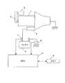
図1は、第1の実施の形態におけるアイドルストップ制御装置の構成を示すブロック図である。スタータモータ2は、ドライバのエンジン始動操作に基づいて、ピニオンギヤ(不図示)をエンジン1のリングギヤ(不図示)に噛み合わせて、フライホイール(不図示)へ動力(回転)を伝えることにより、エンジン1の始動を行う。-First embodiment-
FIG. 1 is a block diagram illustrating a configuration of an idle stop control device according to the first embodiment. The
モータジェネレータ5は、ベルト6によってエンジン1に連結されており、エンジン1を駆動源としてジェネレータ(発電機)として機能するとともに、アイドルストップからの再始動時にエンジン1を始動するモータとしても機能する。 The
バッテリ3は、スタータモータ2およびモータジェネレータ5に電流を供給する。電圧センサ7は、バッテリ3の電圧を検出して、ECU4に出力する。電流センサ8は、バッテリ3の充放電電流を検出して、ECU4に出力する。 The battery 3 supplies current to the
メモリ9は、スタータモータ2によってエンジン始動を行った場合のバッテリ最低電圧と、モータジェネレータ5によってエンジン始動を行った場合のバッテリ最低電圧との電圧差のデータを記憶する。 The
ECU4は、アイドルストップの制御を含むエンジン1の全般的な制御を行う。特に、ECU4は、後述するように、モータジェネレータ5によってエンジンを始動させる場合のバッテリ最低電圧を推定し、推定したバッテリ最低電圧に基づいて、アイドルストップの可否を判定する。 The ECU 4 performs overall control of the
図2は、スタータモータ2によってエンジン始動を行った場合のバッテリ電圧と、モータジェネレータ5によってエンジン始動を行った場合のバッテリ電圧との電圧差を検出する処理手順を示すフローチャートである。車両が起動すると、ECU4は、ステップS10の処理を開始する。 FIG. 2 is a flowchart showing a processing procedure for detecting a voltage difference between the battery voltage when the engine is started by the
ステップS10では、スタータモータ2によるエンジン始動時のバッテリ最低電圧V1を検出する。エンジン始動時には、バッテリ3からスタータモータ2に電流を供給するため、バッテリ3の電圧が一時的に大きく低下する。ECU4は、電圧センサ7によって検出されるバッテリ電圧を繰り返し取得し、バッテリ電圧が最も低下した時の電圧を、スタータモータ2によるエンジン始動時のバッテリ最低電圧V1として検出する。なお、エンジン始動時のバッテリ電圧の低下量は、エンジン1をクランキングさせる際の機械的負荷や電気的負荷、また、バッテリ3の劣化度合い等によって異なる。 In step S10, the lowest battery voltage V1 when the engine is started by the
ステップS20では、モータジェネレータ5によるエンジン再始動時、すなわち、アイドルストップからのエンジン再始動時におけるバッテリ最低電圧V2を検出する。ここでも、ECU4は、電圧センサ7によって検出されるバッテリ電圧を繰り返し取得し、バッテリ電圧が最も低下した時の電圧を、モータジェネレータ5によるエンジン再始動時のバッテリ最低電圧V2として検出する。 In step S20, the battery minimum voltage V2 at the time of engine restart by the
ステップS30では、ステップS10で求めたバッテリ最低電圧V1から、ステップS20で求めたバッテリ最低電圧V2を減算することにより、電圧差ΔV(=V1−V2)を求める。求めた電圧差ΔVは、メモリ9に記憶させておく。 In step S30, the voltage difference ΔV (= V1−V2) is obtained by subtracting the battery minimum voltage V2 obtained in step S20 from the battery minimum voltage V1 obtained in step S10. The obtained voltage difference ΔV is stored in the
図3は、ECU4によって行われるアイドルストップ制御の処理手順を示すフローチャートである。車両が起動すると、ECU4は、ステップS100の処理を開始する。 FIG. 3 is a flowchart showing a processing procedure of idle stop control performed by the ECU 4. When the vehicle is activated, the ECU 4 starts the process of step S100.
ステップS100では、スタータモータ2によるエンジン始動時のバッテリ最低電圧V1’を検出する。このバッテリ最低電圧V1’も、エンジン始動時にバッテリ3の電圧が最も低下した時の電圧である。 In step S100, the lowest battery voltage V1 'when the
ステップS110では、モータジェネレータ5によるエンジン再始動時におけるバッテリ最低電圧V2’を算出する。具体的には、ステップS100で検出したバッテリ最低電圧V1’から、メモリ9に記憶させた電圧差ΔVを減算することにより、モータジェネレータ5によるエンジン再始動時のバッテリ最低電圧V2’を算出する。このバッテリ最低電圧V2’は、モータジェネレータ5によってエンジン1の再始動を行う場合において、バッテリ3の電圧が最も低下した時の推定電圧値である。 In step S110, the battery minimum voltage V2 'when the
ここで、メモリ9に複数の電圧差ΔVのデータが記憶されている場合、最新の電圧差ΔVを用いてもよいし、複数の電圧差ΔVの平均値を算出して用いてもよい。また、平均値を算出する際に、直近の所定数の電圧差ΔVを用いるようにしてもよい。 Here, when data of a plurality of voltage differences ΔV are stored in the
ステップS120では、ステップS110で算出したバッテリ最低電圧V2’が所定の判定電圧Vthより大きいか否かを判定する。所定の判定電圧Vthは、エンジン1を始動するために必要な駆動電流をモータジェネレータ5に供給し得ることを保証する電圧、あるいはECU4がリセットすることがないようECU4の作動を保証する電圧であり、実験等を行うことによって、予め適切な値に設定しておく。本実施の形態では、バッテリ3の性能や経年劣化、および、モータジェネレータ5の性能等に応じて、モータジェネレータ5によってエンジン1を始動する際のバッテリ最低電圧を精度良く求めることができるので、バッテリ3の性能バラツキや経年劣化、および、モータジェネレータ5の性能バラツキ等を考慮せずに、判定電圧Vthを設定することができる。バッテリ最低電圧V2’が所定の判定電圧Vthより大きいと判定すると、ステップS130に進み、所定の判定電圧Vth以下であると判定すると、ステップS130に進む。 In step S120, it is determined whether or not the minimum battery voltage V2 'calculated in step S110 is greater than a predetermined determination voltage Vth. The predetermined determination voltage Vth is a voltage that guarantees that the drive current necessary for starting the
ステップS130では、アイドルストップを許可する。これにより、所定のアイドルストップ条件が成立(例えば、車速が0km/hでブレーキペダルを踏んだとき)した際に、ECU4は、エンジン1を停止させる。また、アイドルストップ中に所定のアイドルストップ解除条件が成立(例えば、ブレーキペダルから足を離したとき)した際には、ECU4は、エンジン1をモータジェネレータ5で再始動させる。 In step S130, idling stop is permitted. Thus, when a predetermined idle stop condition is satisfied (for example, when the brake pedal is depressed at a vehicle speed of 0 km / h), the ECU 4 stops the
一方、ステップS140では、アイドルストップを禁止する。例えば、アイドルストップ禁止フラグをセットすることによって、所定のアイドルストップ条件が成立した場合でも、ECU4は、エンジン1を停止させる処理を行わない。 On the other hand, in step S140, idle stop is prohibited. For example, the ECU 4 does not perform the process of stopping the
第1の実施の形態におけるアイドルストップ制御装置によれば、スタータモータ2によるエンジン始動時のバッテリ最低電圧と、モータジェネレータ5によるエンジン始動時のバッテリ最低電圧との電圧差ΔVを求めておき、スタータモータ2によるエンジン始動時のバッテリ最低電圧と、求めておいた電圧差ΔVとに基づいて、モータジェネレータ5によってエンジン1を始動する際のバッテリ最低電圧を算出し、算出したバッテリ最低電圧が所定の判定電圧Vthより高い場合に、アイドルストップを許可し、所定の判定電圧以下の場合に、アイドルストップを禁止する。これにより、ドライバの始動操作に応じてエンジンを始動する始動装置(スタータモータ2)と、所定のアイドルストップ解除条件に応じてエンジンを始動する始動装置(モータジェネレータ5)とが異なるアイドルストップ制御装置でも、アイドルストップの可否を判定できる。すなわち、スタータモータ2によるエンジン始動時のバッテリ最低電圧と、モータジェネレータ5によるエンジン始動時のバッテリ最低電圧との間には所定の電圧差ΔVを有するため、スタータモータ2によるエンジン始動時のバッテリ最低電圧を検出しておけば、この電圧差ΔVを用いることによって、モータジェネレータ5によるエンジン1を始動する際のバッテリ最低電圧が推定でき、アイドルストップ可否判定が可能となる。 According to the idling stop control apparatus in the first embodiment, the voltage difference ΔV between the minimum battery voltage when the engine is started by the
また、スタータモータ2によるエンジン始動時のバッテリ最低電圧と、モータジェネレータ5によるエンジン始動時のバッテリ最低電圧とをそれぞれ電圧センサ7で検出して電圧差ΔVを求め、スタータモータ2によるエンジン始動時のバッテリ最低電圧と、求めておいた電圧差ΔVとに基づいて、モータジェネレータ5によってエンジン1を始動する際のバッテリ最低電圧を算出する。これにより、バッテリやモータジェネレータの性能等に応じて、モータジェネレータ5によってエンジン1を始動する際のバッテリ最低電圧を精度良く求めることができる。また、バッテリ3が劣化した場合でも、劣化状態に応じて、モータジェネレータ5によるエンジン始動時のバッテリ最低電圧を求めることができる。従って、バッテリ3の性能のバラツキやバッテリ3の経年劣化、また、モータジェネレータ5の性能バラツキ等を考慮せずに、判定電圧Vthを設定することができ、アイドルストップの頻度を高くすることができる。 Also, the
なお、本実施形態では、スタータモータ2によるエンジン始動時のバッテリ最低電圧と、モータジェネレータ5によるエンジン始動時におけるバッテリ最低電圧とを電圧センサ7で検出して電圧差ΔVを求めたが、電圧差ΔVを固定値として予めメモリ9に記憶させておいても構わない。 In the present embodiment, the voltage difference ΔV is obtained by detecting the minimum battery voltage at the start of the engine by the
また、本実施形態では、モータジェネレータ5によるエンジン再始動時におけるバッテリ最低電圧V2’が所定の判定電圧Vth以下であると判定するとアイドルストップを禁止しているが、アイドルストップを禁止せず、モータジェネレータ5によるエンジンの再始動を止めて、その代わりにスタータモータ2によってエンジンを再始動させても構わない。すなわち、モータジェネレータ5によるエンジン再始動時におけるバッテリ最低電圧V2’が所定の判定電圧Vth以下の場合には、アイドルストップ解除条件に応じたモータジェネレータ5によるエンジンの始動を禁止する。 In this embodiment, when it is determined that the battery minimum voltage V2 ′ at the time of engine restart by the
−第2の実施の形態−
第1の実施の形態では、スタータモータ2によるエンジン始動時のバッテリ最低電圧V1と、モータジェネレータ5によるエンジン再始動時のバッテリ最低電圧V2との差ΔVは、変化しないものとして、スタータモータ2によるエンジン始動時のバッテリ最低電圧V1’から電圧差ΔVを減算することによって、モータジェネレータ5でエンジン再始動を行う際の推定バッテリ最低電圧V2’を算出した。しかしながら、スタータモータ2によるエンジン始動後に、バッテリ3の充放電が行われると、バッテリ3のV−I特性が変化するため、電圧差ΔVも変化する。第2の実施の形態におけるアイドルストップ制御装置では、スタータモータ2によるエンジン始動後のバッテリ3の充放電量に基づいて、電圧差ΔVを補正する。-Second Embodiment-
In the first embodiment, the difference ΔV between the lowest battery voltage V1 when the
図4は、第2の実施の形態におけるアイドルストップ制御装置によって行われるアイドルストップ制御の処理手順を示すフローチャートである。図3に示すフローチャートの処理と同一の処理については、同一の符号を付して詳しい説明は省略する。車両が起動すると、ECU4は、ステップS100の処理を開始する。 FIG. 4 is a flowchart showing a processing procedure of idle stop control performed by the idle stop control device according to the second embodiment. The same processes as those in the flowchart shown in FIG. 3 are denoted by the same reference numerals, and detailed description thereof is omitted. When the vehicle is activated, the ECU 4 starts the process of step S100.
ステップS100において、スタータモータ2によるエンジン始動時のバッテリ最低電圧V1’を検出すると、ステップS400に進む。ステップS400では、電流センサ8によって検出される充放電電流に基づいて、例えば、電流積算等の既知の方法により、バッテリ3の充放電量を算出する。 In step S100, when the battery minimum voltage V1 'when the engine is started by the
ステップS410では、メモリ9に記憶されている電圧差ΔVを読み出して、ステップS400で算出した充放電量に基づいて補正する。具体的には、バッテリ3の充電量が放電量よりも多く、ステップS400で充電量が算出された場合には、電圧差ΔVを小さくする補正を行う。逆に、バッテリ3の放電量が充電量よりも多く、ステップS400で放電量が算出された場合には、電圧差ΔVを大きくする補正を行う。 In step S410, the voltage difference ΔV stored in the
このときに、充電量が多いほど、電圧差ΔVを小さくする度合いを大きくし、放電量が多いほど、電圧差ΔVを大きくする度合いを大きくする。例えば、充電量および放電量と、電圧差ΔVの補正量との関係を定めたテーブルデータを予め用意しておき、ステップS400で算出した充放電量に基づいて、テーブルデータを参照して、電圧差ΔVの補正量を求めて、電圧差ΔVを補正するようにしてもよい。 At this time, the greater the amount of charge, the greater the degree of decreasing the voltage difference ΔV, and the greater the amount of discharge, the greater the degree of increasing the voltage difference ΔV. For example, table data that defines the relationship between the charge amount and the discharge amount and the correction amount of the voltage difference ΔV is prepared in advance, and the voltage is determined by referring to the table data based on the charge / discharge amount calculated in step S400. The correction amount of the difference ΔV may be obtained to correct the voltage difference ΔV.
ステップS110以降の処理は、図3に示すフローチャートのステップS110以降の処理と同じである。 The processing after step S110 is the same as the processing after step S110 in the flowchart shown in FIG.
第2の実施の形態におけるアイドルストップ制御装置によれば、スタータモータ2によるエンジン始動時のバッテリ最低電圧と、モータジェネレータ5によるエンジン始動時のバッテリ最低電圧との電圧差ΔVを、バッテリ3の充放電量に基づいて補正するので、バッテリ3の状態に応じて、モータジェネレータ5によってエンジン1を始動する際のバッテリ最低電圧V2’をさらに精度良く求めることができる。これにより、バッテリ3のSOCを考慮せずに、判定電圧Vthを設定することができ、アイドルストップの頻度を高くすることができる。 According to the idle stop control device of the second embodiment, the voltage difference ΔV between the lowest battery voltage at the start of the engine by the
−第3の実施の形態−
第1の実施の形態では、スタータモータ2によるエンジン始動時のバッテリ最低電圧V1と、モータジェネレータ5によるエンジン再始動時のバッテリ最低電圧V2との差ΔVは、変化しないものとして、スタータモータ2によるエンジン始動時のバッテリ最低電圧V1’から電圧差ΔVを減算することによって、モータジェネレータ5でエンジン再始動を行う際の推定バッテリ最低電圧V2’を算出した。しかしながら、スタータモータ2によるエンジン始動後に、バッテリ3の温度が変化すると、バッテリ3のV−I特性が変化するため、電圧差ΔVも変化する。第3の実施の形態におけるアイドルストップ制御装置では、スタータモータ2によるエンジン始動後のバッテリ3の温度変化量に基づいて、電圧差ΔVを補正する。-Third embodiment-
In the first embodiment, the difference ΔV between the lowest battery voltage V1 when the
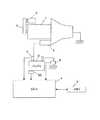
図5は、第3の実施の形態におけるアイドルストップ制御装置の構成を示すブロック図である。第3の実施の形態におけるアイドルストップ制御装置は、図1に示す第1の実施の形態におけるアイドルストップ制御装置の構成に対して、バッテリ3の温度を検出する温度センサ50が追加されている。 FIG. 5 is a block diagram illustrating a configuration of an idle stop control device according to the third embodiment. In the idle stop control device in the third embodiment, a
図6は、第3の実施の形態におけるアイドルストップ制御装置によって行われるアイドルストップ制御の処理手順を示すフローチャートである。図3に示すフローチャートの処理と同一の処理については、同一の符号を付して詳しい説明は省略する。車両が起動すると、ECU4は、ステップS100の処理を開始する。 FIG. 6 is a flowchart illustrating a processing procedure of idle stop control performed by the idle stop control device according to the third embodiment. The same processes as those in the flowchart shown in FIG. 3 are denoted by the same reference numerals, and detailed description thereof is omitted. When the vehicle is activated, the ECU 4 starts the process of step S100.
ステップS100において、スタータモータ2によるエンジン始動時のバッテリ最低電圧V1’を検出すると、ステップS600に進む。ステップS600では、スタータモータ2によるエンジン始動時に温度センサ50で検出されたバッテリ温度T1と、その後に温度センサ50で検出されるバッテリ温度T2との温度差ΔT(=T2−T1)を求める。図6に示すフローチャートの処理は繰り返し行われるため、バッテリ温度T2は、ステップS600の処理を行うタイミングで温度センサ50によって検出される温度である。 In step S100, when the battery minimum voltage V1 'when the engine is started by the
ステップS610では、メモリ9に記憶されている電圧差ΔVを読み出して、ステップS600で算出した温度差ΔTに基づいて補正する。具体的には、温度差ΔTが大きくなるほど、電圧差ΔVを小さくする補正を行う。 In step S610, the voltage difference ΔV stored in the
ステップS110以降の処理は、図3に示すフローチャートのステップS110以降の処理と同じである。 The processing after step S110 is the same as the processing after step S110 in the flowchart shown in FIG.
第3の実施の形態におけるアイドルストップ制御装置によれば、スタータモータ2によるエンジン始動時のバッテリ最低電圧と、モータジェネレータ5によるエンジン始動時のバッテリ最低電圧との電圧差ΔVを、バッテリ3の温度変化量に基づいて補正するので、バッテリ3の状態に応じて、モータジェネレータ5によってエンジン1を始動する際のバッテリ最低電圧V2’をさらに精度良く求めることができる。これにより、バッテリ3の温度変化を考慮せずに、判定電圧Vthを設定することができ、アイドルストップの頻度を高くすることができる。 According to the idle stop control device in the third embodiment, the voltage difference ΔV between the lowest battery voltage at the start of the engine by the
本発明は、上述した第1〜第3の実施の形態に限定されることはなく、その技術的思想の範囲内でなしうる様々な変更、改良が含まれることは言うまでもない。例えば、上述した各実施の形態では、モータジェネレータ5によるエンジン始動時のバッテリ電圧低下量がスタータモータ2によるエンジン始動時のバッテリ電圧低下量よりも大きいものとして、スタータモータ2によるエンジン始動時のバッテリ最低電圧V1から、モータジェネレータ5によるエンジン始動時のバッテリ最低電圧V2を減算することによって、電圧差ΔVを求めた。しかし、スタータモータ2によるエンジン始動時のバッテリ電圧低下量がモータジェネレータ5によるエンジン始動時のバッテリ電圧低下量よりも大きい場合には、モータジェネレータ5によるエンジン始動時のバッテリ最低電圧V2からスタータモータ2によるエンジン始動時のバッテリ最低電圧V1を減算することによって、電圧差ΔVを求め、スタータモータ2によるエンジン始動時のバッテリ最低電圧V1’に電圧差ΔVを加算することによって、モータジェネレータ5によってエンジン1を始動する際のバッテリ最低電圧V2’を算出する。この場合、スタータモータ2によるエンジン始動後のバッテリ3の充電量が多いほど、電圧差ΔVを大きくする補正を行い、エンジン始動後のバッテリ3の放電量が多いほど、電圧差ΔVを小さくする。また、スタータモータ2によるエンジン始動後のバッテリ3の温度変化量ΔTが大きくなるほど、電圧差を大きくする補正を行う。 The present invention is not limited to the first to third embodiments described above, and it is needless to say that various changes and improvements that can be made within the scope of the technical idea are included. For example, in each of the above-described embodiments, it is assumed that the battery voltage drop when the engine is started by the
1…エンジン
2…スタータモータ
3…バッテリ
4…ECU
5…モータジェネレータ
6…ベルト
7…電圧センサ
8…電流センサ
9…メモリ
50…温度センサ
電圧センサ7、ECU4、図2のS10,S20…バッテリ電圧検出手段
ECU4、図2のS30…電圧差算出手段
メモリ9…記憶手段
ECU4、S110…バッテリ電圧推定手段
ECU4、S120〜S140…制御手段
ECU4、S400…充放電量算出手段
ECU4、S410,S610…電圧差補正手段
温度センサ50…バッテリ温度検出手段
ECU4、S600…バッテリ温度変化量算出手段DESCRIPTION OF
DESCRIPTION OF
Claims (8)
Translated fromJapaneseドライバの始動操作に応じて、前記エンジンへ動力を伝達することにより、前記エンジンを始動する第1の始動装置と、
所定のアイドルストップ解除条件に応じて、ベルト機構を介して前記エンジンへ動力を伝達することにより、前記エンジンを始動する第2の始動装置と、
前記第1の始動装置および前記第2の始動装置に電流を供給するバッテリの電圧を検出するバッテリ電圧検出手段と、
前記第1の始動装置によるエンジン始動時におけるバッテリの最低電圧と、前記第2の始動装置によるエンジン始動時におけるバッテリの最低電圧との電圧差を記憶する記憶手段と、
前記第1の始動装置によるエンジン始動時に前記バッテリ電圧検出手段によって検出されるバッテリの最低電圧と、前記記憶手段に記憶されている電圧差とに基づいて、前記第2の始動装置によるエンジン始動時におけるバッテリの最低電圧を推定するバッテリ電圧推定手段と、
前記バッテリ電圧推定手段によって推定されたバッテリ最低電圧が所定のバッテリ電圧以下の場合に、アイドルストップ解除条件に応じた第2の始動装置によるエンジンの始動を禁止する制御手段と、
を備えることを特徴とするアイドルストップ制御装置。An idle stop control device that automatically stops the engine when a predetermined idle stop condition is satisfied,
A first starter for starting the engine by transmitting power to the engine in response to a start operation of the driver;
A second starter for starting the engine by transmitting power to the engine via a belt mechanism according to a predetermined idle stop release condition;
Battery voltage detection means for detecting a voltage of a battery for supplying current to the first starter and the second starter;
Storage means for storing a voltage difference between a minimum voltage of the battery at the time of starting the engine by the first starter and a minimum voltage of the battery at the time of starting the engine by the second starter;
When the engine is started by the second starter, based on the lowest battery voltage detected by the battery voltage detector when the engine is started by the first starter and the voltage difference stored in the storage unit Battery voltage estimating means for estimating the minimum battery voltage in
Control means for prohibiting start of the engine by the second starter according to the idle stop release condition when the minimum battery voltage estimated by the battery voltage estimation means is less than or equal to a predetermined battery voltage;
An idle stop control device comprising:
前記記憶手段は、前記電圧差算出手段によって算出される電圧差を記憶することを特徴とする請求項1に記載のアイドルストップ制御装置。A minimum battery voltage detected by the battery voltage detection means when the engine is started by the first starter and a minimum battery voltage detected by the battery voltage detection means when the engine is started by the second starter A voltage difference calculating means for calculating the voltage difference;
The idle stop control device according to claim 1, wherein the storage unit stores the voltage difference calculated by the voltage difference calculation unit.
前記第1の始動装置によるエンジン始動後のバッテリの充放電量に基づいて、前記電圧差を補正する電圧差補正手段と、
をさらに備え、
前記バッテリ電圧推定手段は、前記第1の始動装置によるエンジン始動時に前記バッテリ電圧検出手段によって検出されるバッテリの最低電圧と、前記補正された電圧差とに基づいて、前記第2の始動装置によるエンジン始動時におけるバッテリの最低電圧を推定することを特徴とする請求項1に記載のアイドルストップ制御装置。Charge / discharge amount calculating means for calculating the charge / discharge amount of the battery;
Voltage difference correction means for correcting the voltage difference based on the charge / discharge amount of the battery after starting the engine by the first starter;
Further comprising
The battery voltage estimating means is based on the second starter based on the minimum battery voltage detected by the battery voltage detector when the engine is started by the first starter and the corrected voltage difference. The idle stop control device according to claim 1, wherein the minimum voltage of the battery at the time of engine start is estimated.
前記第1の始動装置によるエンジン始動後のバッテリ温度の変化量を算出するバッテリ温度変化量算出手段と、
前記バッテリ温度の変化量に基づいて、前記電圧差を補正する電圧差補正手段と、
をさらに備え、
前記バッテリ電圧推定手段は、前記第1の始動装置によるエンジン始動時に前記バッテリ電圧検出手段によって検出されるバッテリの最低電圧と、前記補正された電圧差とに基づいて、前記第2の始動装置によるエンジン始動時におけるバッテリの最低電圧を推定することを特徴とする請求項1に記載のアイドルストップ制御装置。Battery temperature detecting means for detecting the temperature of the battery;
Battery temperature change amount calculating means for calculating a change amount of the battery temperature after the engine is started by the first starter;
Voltage difference correction means for correcting the voltage difference based on the amount of change in the battery temperature;
Further comprising
The battery voltage estimating means is based on the second starter based on the minimum battery voltage detected by the battery voltage detector when the engine is started by the first starter and the corrected voltage difference. The idle stop control device according to claim 1, wherein the minimum voltage of the battery at the time of engine start is estimated.
ドライバの始動操作に応じて、前記エンジンへ動力を伝達することにより、前記エンジンを始動する第1の始動装置によるエンジン始動時におけるバッテリの最低電圧と、所定のアイドルストップ解除条件に応じて、ベルト機構を介して前記エンジンへ動力を伝達することにより、前記エンジンを始動する第2の始動装置によるエンジン始動時におけるバッテリの最低電圧との電圧差を記憶し、
前記第1の始動装置によるエンジン始動時に検出されたバッテリの最低電圧と、前記電圧差とに基づいて、前記第2の始動装置によるエンジン始動時におけるバッテリの最低電圧を推定し、
前記推定したバッテリ最低電圧が所定のバッテリ電圧以下の場合に、アイドルストップ解除条件に応じた第2の始動装置によるエンジンの始動を禁止する、
ことを特徴とするアイドルストップ制御方法。An idle stop control method for automatically stopping the engine when a predetermined idle stop condition is satisfied,
By transmitting power to the engine in accordance with the start operation of the driver, the belt according to the minimum voltage of the battery at the time of engine start by the first starter that starts the engine and the predetermined idle stop release condition Storing the voltage difference from the lowest voltage of the battery at the time of engine start by the second starter for starting the engine by transmitting power to the engine via a mechanism;
Based on the minimum voltage of the battery detected at the time of starting the engine by the first starter and the voltage difference, the minimum voltage of the battery at the time of starting the engine by the second starter is estimated,
When the estimated minimum battery voltage is equal to or lower than a predetermined battery voltage, the engine start by the second starter according to the idle stop release condition is prohibited.
An idle stop control method characterized by the above.
Priority Applications (4)
| Application Number | Priority Date | Filing Date | Title |
|---|---|---|---|
| JP2009264054AJP5327012B2 (en) | 2009-02-24 | 2009-11-19 | Idle stop control device and idle stop control method |
| AT10000770TATE539935T1 (en) | 2009-02-24 | 2010-01-26 | IDLE STOP CONTROL DEVICE AND METHOD THEREOF |
| EP10000770AEP2221226B1 (en) | 2009-02-24 | 2010-01-26 | Idle stop control apparatus and method thereof |
| CN2010101253127ACN101813030B (en) | 2009-02-24 | 2010-02-24 | Idle stop control apparatus and method thereof |
Applications Claiming Priority (3)
| Application Number | Priority Date | Filing Date | Title |
|---|---|---|---|
| JP2009040357 | 2009-02-24 | ||
| JP2009040357 | 2009-02-24 | ||
| JP2009264054AJP5327012B2 (en) | 2009-02-24 | 2009-11-19 | Idle stop control device and idle stop control method |
Publications (2)
| Publication Number | Publication Date |
|---|---|
| JP2010223215A JP2010223215A (en) | 2010-10-07 |
| JP5327012B2true JP5327012B2 (en) | 2013-10-30 |
Family
ID=42122849
Family Applications (1)
| Application Number | Title | Priority Date | Filing Date |
|---|---|---|---|
| JP2009264054AExpired - Fee RelatedJP5327012B2 (en) | 2009-02-24 | 2009-11-19 | Idle stop control device and idle stop control method |
Country Status (4)
| Country | Link |
|---|---|
| EP (1) | EP2221226B1 (en) |
| JP (1) | JP5327012B2 (en) |
| CN (1) | CN101813030B (en) |
| AT (1) | ATE539935T1 (en) |
Families Citing this family (39)
| Publication number | Priority date | Publication date | Assignee | Title |
|---|---|---|---|---|
| DE102010041631B4 (en) | 2010-09-29 | 2016-12-15 | Bayerische Motoren Werke Aktiengesellschaft | Vehicle drive with at least two starting systems |
| CN101994586B (en)* | 2010-09-29 | 2013-01-30 | 重庆长安汽车股份有限公司 | Idling start-stop control system for automobile engine |
| JP5672917B2 (en)* | 2010-09-30 | 2015-02-18 | 株式会社アドヴィックス | Vehicle control device |
| CN103210208B (en)* | 2010-11-17 | 2016-11-16 | 大陆汽车有限责任公司 | For determining the apparatus and method of the startability of internal combustion engine |
| KR101189380B1 (en) | 2010-11-30 | 2012-10-10 | 현대자동차주식회사 | ISG entry apparatus and method |
| KR101755691B1 (en) | 2011-05-03 | 2017-07-20 | 현대자동차주식회사 | Ventilating Condition Determine Method of Idel Stop and Go Function |
| RU2573687C2 (en)* | 2011-11-18 | 2016-01-27 | Тойота Дзидося Кабусики Кайся | Device for control over vehicle, vehicle and method for its control |
| JP5853690B2 (en)* | 2011-12-28 | 2016-02-09 | 日産自動車株式会社 | Automatic engine stop control device for vehicle |
| JP5881508B2 (en)* | 2012-03-30 | 2016-03-09 | 本田技研工業株式会社 | Idle stop control device for motorcycles |
| JP5594343B2 (en)* | 2012-10-02 | 2014-09-24 | トヨタ自動車株式会社 | Control device, vehicle, and control method |
| US9102334B2 (en) | 2012-10-29 | 2015-08-11 | Deere & Company | Methods and apparatus to control motors |
| JP6143439B2 (en)* | 2012-11-21 | 2017-06-07 | ダイハツ工業株式会社 | Control device for internal combustion engine |
| DE102013009220A1 (en)* | 2013-05-31 | 2014-12-04 | Volkswagen Aktiengesellschaft | Method for operating a vehicle with an internal combustion engine with a start-stop function |
| JP6236936B2 (en)* | 2013-07-03 | 2017-11-29 | 日産自動車株式会社 | Automatic engine stop control device for vehicle |
| DE102013017784A1 (en)* | 2013-10-25 | 2015-04-30 | Audi Ag | Motor vehicle and method for mounting a motor vehicle |
| JP6214430B2 (en)* | 2014-02-28 | 2017-10-18 | ダイハツ工業株式会社 | Control device for idle stop car |
| DE102014219221B4 (en)* | 2014-09-24 | 2022-12-01 | Robert Bosch Gmbh | Method for starting an internal combustion engine of a motor vehicle |
| DE102015224109A1 (en)* | 2015-12-02 | 2017-06-08 | Bayerische Motoren Werke Aktiengesellschaft | Start-stop device for initiating an automatic shutdown of a prime mover of a motor vehicle |
| JP6547676B2 (en)* | 2016-05-12 | 2019-07-24 | 株式会社デンソー | Engine start control system |
| US10112603B2 (en) | 2016-12-14 | 2018-10-30 | Bendix Commercial Vehicle Systems Llc | Front end motor-generator system and hybrid electric vehicle operating method |
| US10640103B2 (en) | 2016-12-14 | 2020-05-05 | Bendix Commercial Vehicle Systems Llc | Front end motor-generator system and hybrid electric vehicle operating method |
| US10220830B2 (en) | 2016-12-14 | 2019-03-05 | Bendix Commercial Vehicle Systems | Front end motor-generator system and hybrid electric vehicle operating method |
| US10343677B2 (en) | 2016-12-14 | 2019-07-09 | Bendix Commercial Vehicle Systems Llc | Front end motor-generator system and hybrid electric vehicle operating method |
| US10363923B2 (en) | 2016-12-14 | 2019-07-30 | Bendix Commercial Vehicle Systems, Llc | Front end motor-generator system and hybrid electric vehicle operating method |
| US10630137B2 (en) | 2016-12-14 | 2020-04-21 | Bendix Commerical Vehicle Systems Llc | Front end motor-generator system and modular generator drive apparatus |
| US10532647B2 (en) | 2016-12-14 | 2020-01-14 | Bendix Commercial Vehicle Systems Llc | Front end motor-generator system and hybrid electric vehicle operating method |
| US10308240B2 (en) | 2016-12-14 | 2019-06-04 | Bendix Commercial Vehicle Systems Llc | Front end motor-generator system and hybrid electric vehicle operating method |
| US10543735B2 (en) | 2016-12-14 | 2020-01-28 | Bendix Commercial Vehicle Systems Llc | Hybrid commercial vehicle thermal management using dynamic heat generator |
| US11807112B2 (en) | 2016-12-14 | 2023-11-07 | Bendix Commercial Vehicle Systems Llc | Front end motor-generator system and hybrid electric vehicle operating method |
| US10486690B2 (en) | 2016-12-14 | 2019-11-26 | Bendix Commerical Vehicle Systems, Llc | Front end motor-generator system and hybrid electric vehicle operating method |
| US10220831B2 (en) | 2016-12-14 | 2019-03-05 | Bendix Commercial Vehicle Systems Llc | Front end motor-generator system and hybrid electric vehicle operating method |
| US10239516B2 (en) | 2016-12-14 | 2019-03-26 | Bendix Commercial Vehicle Systems Llc | Front end motor-generator system and hybrid electric vehicle operating method |
| US10479180B2 (en) | 2016-12-14 | 2019-11-19 | Bendix Commercial Vehicle Systems Llc | Front end motor-generator system and hybrid electric vehicle operating method |
| JP2019190347A (en)* | 2018-04-24 | 2019-10-31 | 株式会社Gsユアサ | Power storage device and method for restarting engine of idling stop vehicle |
| CN108644022B (en)* | 2018-05-14 | 2020-06-23 | 潍柴西港新能源动力有限公司 | Natural gas engine hot shutdown detection control method |
| CN108775269B (en)* | 2018-05-28 | 2020-11-27 | 重庆工商大学 | A kind of engine automatic start-stop control method and device for hybrid loader |
| US10895286B2 (en) | 2018-06-14 | 2021-01-19 | Bendix Commercial Vehicle Systems, Llc | Polygonal spring coupling |
| US10663006B2 (en) | 2018-06-14 | 2020-05-26 | Bendix Commercial Vehicle Systems Llc | Polygon spring coupling |
| JP7521554B2 (en)* | 2022-04-07 | 2024-07-24 | トヨタ自動車株式会社 | Vehicle control device |
Family Cites Families (11)
| Publication number | Priority date | Publication date | Assignee | Title |
|---|---|---|---|---|
| JPS58140434A (en)* | 1982-02-16 | 1983-08-20 | Nissan Motor Co Ltd | Engine controller |
| JP3520682B2 (en) | 1996-07-31 | 2004-04-19 | スズキ株式会社 | Automatic engine start / stop device |
| JP2001304008A (en)* | 2000-04-25 | 2001-10-31 | Nissan Motor Co Ltd | Vehicle control device |
| JP2003041967A (en) | 2001-07-26 | 2003-02-13 | Toyota Motor Corp | Automatic stop control device for internal combustion engine |
| JP2003286930A (en)* | 2002-03-28 | 2003-10-10 | Nissan Motor Co Ltd | Engine starter |
| JP4003530B2 (en)* | 2002-05-08 | 2007-11-07 | 株式会社デンソー | ENGINE START SYSTEM, ENGINE START METHOD, AND START CONTROL DEVICE |
| JP3985621B2 (en)* | 2002-07-19 | 2007-10-03 | 株式会社デンソー | ENGINE START DEVICE, START CONTROL DEVICE, START SYSTEM, AND START METHOD |
| JP4158633B2 (en)* | 2003-07-24 | 2008-10-01 | 三菱自動車工業株式会社 | Engine start control device for idle stop car |
| JP2005146939A (en)* | 2003-11-13 | 2005-06-09 | Matsushita Electric Ind Co Ltd | Engine startability predicting device and starting storage battery equipped with the same |
| CN101181874A (en)* | 2007-12-04 | 2008-05-21 | 奇瑞汽车有限公司 | Management system for electric automobile battery |
| CN101235781B (en)* | 2007-12-29 | 2010-06-09 | 奇瑞汽车股份有限公司 | Engine pedestal control system possessing idle speed shutdown /start-up function |
- 2009
- 2009-11-19JPJP2009264054Apatent/JP5327012B2/ennot_activeExpired - Fee Related
- 2010
- 2010-01-26ATAT10000770Tpatent/ATE539935T1/enactive
- 2010-01-26EPEP10000770Apatent/EP2221226B1/ennot_activeNot-in-force
- 2010-02-24CNCN2010101253127Apatent/CN101813030B/ennot_activeExpired - Fee Related
Also Published As
| Publication number | Publication date |
|---|---|
| EP2221226A1 (en) | 2010-08-25 |
| CN101813030B (en) | 2013-06-05 |
| JP2010223215A (en) | 2010-10-07 |
| ATE539935T1 (en) | 2012-01-15 |
| EP2221226B1 (en) | 2012-01-04 |
| CN101813030A (en) | 2010-08-25 |
Similar Documents
| Publication | Publication Date | Title |
|---|---|---|
| JP5327012B2 (en) | Idle stop control device and idle stop control method | |
| JP4919120B2 (en) | Battery state detection device | |
| JP4499810B2 (en) | In-vehicle battery state estimation device | |
| US8111037B2 (en) | Method for battery state-of-health monitoring using battery voltage during vehicle starting | |
| JP4866187B2 (en) | Battery control device, electric vehicle, and program for causing computer to execute processing for estimating charge state of secondary battery | |
| CN104838560B (en) | Battery charge controller, charge control method | |
| CN105765213B (en) | The control system and control method of vehicle | |
| US20070193796A1 (en) | Economical running control apparatus | |
| JP2009255742A (en) | Battery state determination device | |
| JP2010024906A (en) | Automatic stop/start device for internal combustion engine | |
| JP6356591B2 (en) | Battery monitoring device | |
| JP7115409B2 (en) | Drive system controller | |
| JP2007287493A (en) | Diagnostic device for internal combustion engine | |
| JP2013024157A (en) | Engine stop/start control device | |
| JP5630316B2 (en) | Automatic start control device for internal combustion engine | |
| JP2010031740A (en) | Battery managing device | |
| JP6167886B2 (en) | Engine control device | |
| JP2007040229A (en) | Automatic engine stopping/starting control device and its method | |
| JP2010221828A (en) | Economy running control device | |
| JP6583718B2 (en) | Battery deterioration judgment device | |
| JP2013164016A (en) | Vehicle control device | |
| JP2014029141A (en) | Battery condition estimation device for internal combustion engine | |
| JP5673578B2 (en) | Vehicle control device | |
| JP6851743B2 (en) | Jumping start judgment device | |
| JP4204335B2 (en) | Vehicle power supply control device |
Legal Events
| Date | Code | Title | Description |
|---|---|---|---|
| A621 | Written request for application examination | Free format text:JAPANESE INTERMEDIATE CODE: A621 Effective date:20120925 | |
| A977 | Report on retrieval | Free format text:JAPANESE INTERMEDIATE CODE: A971007 Effective date:20130617 | |
| TRDD | Decision of grant or rejection written | ||
| A01 | Written decision to grant a patent or to grant a registration (utility model) | Free format text:JAPANESE INTERMEDIATE CODE: A01 Effective date:20130625 | |
| A61 | First payment of annual fees (during grant procedure) | Free format text:JAPANESE INTERMEDIATE CODE: A61 Effective date:20130708 | |
| R150 | Certificate of patent or registration of utility model | Ref document number:5327012 Country of ref document:JP Free format text:JAPANESE INTERMEDIATE CODE: R150 Free format text:JAPANESE INTERMEDIATE CODE: R150 | |
| LAPS | Cancellation because of no payment of annual fees |