JP5325976B2 - Medical robot and method for meeting performance requirements of medical robot - Google Patents
Medical robot and method for meeting performance requirements of medical robotDownload PDFInfo
- Publication number
- JP5325976B2 JP5325976B2JP2011507890AJP2011507890AJP5325976B2JP 5325976 B2JP5325976 B2JP 5325976B2JP 2011507890 AJP2011507890 AJP 2011507890AJP 2011507890 AJP2011507890 AJP 2011507890AJP 5325976 B2JP5325976 B2JP 5325976B2
- Authority
- JP
- Japan
- Prior art keywords
- medical
- robot
- tool
- medical robot
- attached
- Prior art date
- Legal status (The legal status is an assumption and is not a legal conclusion. Google has not performed a legal analysis and makes no representation as to the accuracy of the status listed.)
- Active
Links
Images


Classifications
- A—HUMAN NECESSITIES
- A61—MEDICAL OR VETERINARY SCIENCE; HYGIENE
- A61B—DIAGNOSIS; SURGERY; IDENTIFICATION
- A61B34/00—Computer-aided surgery; Manipulators or robots specially adapted for use in surgery
- A61B34/30—Surgical robots
- A—HUMAN NECESSITIES
- A61—MEDICAL OR VETERINARY SCIENCE; HYGIENE
- A61B—DIAGNOSIS; SURGERY; IDENTIFICATION
- A61B90/00—Instruments, implements or accessories specially adapted for surgery or diagnosis and not covered by any of the groups A61B1/00 - A61B50/00, e.g. for luxation treatment or for protecting wound edges
- A61B90/90—Identification means for patients or instruments, e.g. tags
- A61B90/98—Identification means for patients or instruments, e.g. tags using electromagnetic means, e.g. transponders
- B—PERFORMING OPERATIONS; TRANSPORTING
- B25—HAND TOOLS; PORTABLE POWER-DRIVEN TOOLS; MANIPULATORS
- B25J—MANIPULATORS; CHAMBERS PROVIDED WITH MANIPULATION DEVICES
- B25J9/00—Programme-controlled manipulators
- B25J9/06—Programme-controlled manipulators characterised by multi-articulated arms
- B—PERFORMING OPERATIONS; TRANSPORTING
- B25—HAND TOOLS; PORTABLE POWER-DRIVEN TOOLS; MANIPULATORS
- B25J—MANIPULATORS; CHAMBERS PROVIDED WITH MANIPULATION DEVICES
- B25J9/00—Programme-controlled manipulators
- B25J9/16—Programme controls
- B25J9/1674—Programme controls characterised by safety, monitoring, diagnostic
- B25J9/1676—Avoiding collision or forbidden zones
- G—PHYSICS
- G05—CONTROLLING; REGULATING
- G05B—CONTROL OR REGULATING SYSTEMS IN GENERAL; FUNCTIONAL ELEMENTS OF SUCH SYSTEMS; MONITORING OR TESTING ARRANGEMENTS FOR SUCH SYSTEMS OR ELEMENTS
- G05B19/00—Programme-control systems
- G05B19/02—Programme-control systems electric
- G05B19/18—Numerical control [NC], i.e. automatically operating machines, in particular machine tools, e.g. in a manufacturing environment, so as to execute positioning, movement or co-ordinated operations by means of programme data in numerical form
- G05B19/406—Numerical control [NC], i.e. automatically operating machines, in particular machine tools, e.g. in a manufacturing environment, so as to execute positioning, movement or co-ordinated operations by means of programme data in numerical form characterised by monitoring or safety
- G05B19/4061—Avoiding collision or forbidden zones
- G—PHYSICS
- G05—CONTROLLING; REGULATING
- G05B—CONTROL OR REGULATING SYSTEMS IN GENERAL; FUNCTIONAL ELEMENTS OF SUCH SYSTEMS; MONITORING OR TESTING ARRANGEMENTS FOR SUCH SYSTEMS OR ELEMENTS
- G05B2219/00—Program-control systems
- G05B2219/30—Nc systems
- G05B2219/33—Director till display
- G05B2219/33199—Transponder
- G—PHYSICS
- G05—CONTROLLING; REGULATING
- G05B—CONTROL OR REGULATING SYSTEMS IN GENERAL; FUNCTIONAL ELEMENTS OF SUCH SYSTEMS; MONITORING OR TESTING ARRANGEMENTS FOR SUCH SYSTEMS OR ELEMENTS
- G05B2219/00—Program-control systems
- G05B2219/30—Nc systems
- G05B2219/45—Nc applications
- G05B2219/45117—Medical, radio surgery manipulator
- G—PHYSICS
- G05—CONTROLLING; REGULATING
- G05B—CONTROL OR REGULATING SYSTEMS IN GENERAL; FUNCTIONAL ELEMENTS OF SUCH SYSTEMS; MONITORING OR TESTING ARRANGEMENTS FOR SUCH SYSTEMS OR ELEMENTS
- G05B2219/00—Program-control systems
- G05B2219/30—Nc systems
- G05B2219/49—Nc machine tool, till multiple
- G05B2219/49137—Store working envelop, limit, allowed zone
- G—PHYSICS
- G05—CONTROLLING; REGULATING
- G05B—CONTROL OR REGULATING SYSTEMS IN GENERAL; FUNCTIONAL ELEMENTS OF SUCH SYSTEMS; MONITORING OR TESTING ARRANGEMENTS FOR SUCH SYSTEMS OR ELEMENTS
- G05B2219/00—Program-control systems
- G05B2219/30—Nc systems
- G05B2219/49—Nc machine tool, till multiple
- G05B2219/49138—Adapt working envelop, limit, allowed zone to speed of tool
- G—PHYSICS
- G05—CONTROLLING; REGULATING
- G05B—CONTROL OR REGULATING SYSTEMS IN GENERAL; FUNCTIONAL ELEMENTS OF SUCH SYSTEMS; MONITORING OR TESTING ARRANGEMENTS FOR SUCH SYSTEMS OR ELEMENTS
- G05B2219/00—Program-control systems
- G05B2219/30—Nc systems
- G05B2219/49—Nc machine tool, till multiple
- G05B2219/49305—Store, memory on tool with control and maintenance data
Landscapes
- Engineering & Computer Science (AREA)
- Health & Medical Sciences (AREA)
- Life Sciences & Earth Sciences (AREA)
- Surgery (AREA)
- Robotics (AREA)
- Heart & Thoracic Surgery (AREA)
- Molecular Biology (AREA)
- Veterinary Medicine (AREA)
- Public Health (AREA)
- General Health & Medical Sciences (AREA)
- Physics & Mathematics (AREA)
- Biomedical Technology (AREA)
- Animal Behavior & Ethology (AREA)
- Medical Informatics (AREA)
- Nuclear Medicine, Radiotherapy & Molecular Imaging (AREA)
- Mechanical Engineering (AREA)
- Electromagnetism (AREA)
- Pathology (AREA)
- Oral & Maxillofacial Surgery (AREA)
- Human Computer Interaction (AREA)
- Manufacturing & Machinery (AREA)
- General Physics & Mathematics (AREA)
- Automation & Control Theory (AREA)
- Manipulator (AREA)
Description
Translated fromJapanese本発明は、医療用ロボット、および医療用ロボットのパフォーマンス要求事項を充足する方法に関する。 The present invention relates to a medical robot and a method for satisfying the performance requirements of a medical robot.
ロボットは、物体の自動式の取扱および/または加工のために工具を装備することができ、複数の運動軸でたとえば向き、位置、作業工程に関してプログラミング可能な作業機械である。ロボットは、通常、ロボットの運動過程を作動中に制御するプログラミング可能な制御部(制御装置)を有している。 A robot is a work machine that can be equipped with tools for automatic handling and / or machining of objects and can be programmed with a plurality of motion axes, for example in terms of orientation, position, work process. The robot usually has a programmable control unit (control device) that controls the movement process of the robot during operation.
ロボットは、たとえば医療用および/または診療用の用途に用いることができる。医療技術における利用範囲は比較的幅広いため、たとえば作業範囲、剛性、耐荷重、または速度能力、加速度能力に関して、それぞれ明確な違いがあり状況によっては互いに競合する要求事項が、使用するロボットに求められる動作挙動(パフォーマンス)に対して課せられる。求められる仕様の充足は、通常、すべてのロボットコンフィギュレーションについて保証されなくてはならず、特に、相応のパフォーマンス特性値が最悪であるコンフィギュレーションの「ワーストケース」について保証されなくてはならない。このことは、たとえばIEC60601−1に定める機械的な過負荷試験で求められており、この試験は医療技術機器の認可の一環として、たとえばドイツでは作業領域内のもっとも不都合な負荷コンフィギュレーションについて、合格が証明されなくてはならない。このことは、ロボットの所与の作業範囲で、非常に保守的な性能仕様につながりうる。 The robot can be used for medical and / or medical applications, for example. Since the range of use in medical technology is relatively wide, for example, there are clear differences in the working range, rigidity, load bearing capacity, speed capability, acceleration capability, etc., and the requirements for the robot to be used are competing with each other depending on the situation. Imposed on behavior. Satisfaction of the required specifications usually has to be guaranteed for all robot configurations, in particular for the “worst case” of configurations where the corresponding performance characteristic values are worst. This is sought, for example, in the mechanical overload test specified in IEC 60601-1, which is passed as part of the approval of medical technology equipment, for example the most inconvenient load configuration in the work area in Germany. Must be proved. This can lead to a very conservative performance specification for a given working range of the robot.
特許文献1は、機械の安全性関連の機能を制御する方法および装置を開示している。機械は機械制御部と、監視領域内でたとえば人間等の物体を検出するためのセンサと、危険領域を設定し、検出された物体が危険領域に入ると安全性関連の機能を発動させるための評価ユニットとを有している。危険領域を設定するために、評価ユニットは機械制御部と結合されており、評価ユニットは、機械の運動制御のために機械制御部により利用される制御信号から、危険領域の設定のために必要なパラメータを導き出すように構成されている。
本発明の課題は、ロボットの性能仕様をさほど保守的に選択しなくてよくするための前提条件を創出することにある。 An object of the present invention is to create a precondition for eliminating the need for conservatively selecting robot performance specifications.
本発明の課題は、医療用ロボットのパフォーマンス要求事項を充足する方法において、
−複数の軸と1つの制御装置とを有するロボットの取付装置に医療用工具を取り付ける方法ステップと、
−制御装置により特に信頼度の高い技術でロボットの作業領域を適合化し、それにより、医療用工具で実行されるべきアプリケーションのパフォーマンス要求事項をロボットが充足するようにする方法ステップと
を有する方法によって解決される。The subject of the present invention is a method for satisfying the performance requirements of a medical robot,
A method step of attaching a medical tool to an attachment device of a robot having a plurality of axes and a control device;
By means of a method comprising adapting the work area of the robot with a particularly reliable technology by means of a control device, so that the robot meets the performance requirements of the application to be executed on the medical tool Solved.
本発明の課題は、複数の可動の軸および取付装置を備えるロボットアームと、ロボットアームの軸を駆動装置によって動かすための制御装置とを有する医療用ロボットによっても解決され、制御装置は特に信頼度の高い技術でロボットの作業領域を適合化するようにセットアップされており、それにより、医療用工具で実行されるべきアプリケーションのパフォーマンス要求事項をロボットが充足するようになっている。 The object of the present invention is also solved by a medical robot having a robot arm having a plurality of movable shafts and an attachment device, and a control device for moving the shaft of the robot arm by a drive device, and the control device is particularly reliable. It is set up to adapt the robot work area with advanced technology, so that the robot meets the performance requirements of the application to be executed on the medical tool.
このように、本発明に基づくロボットによって、本発明の方法を実施することができる。 Thus, the method of the present invention can be carried out by a robot based on the present invention.
本発明による方法の一態様はロボットの作業領域の適合化であり、それにより、医療用工具で実行されるべきアプリケーションのパフォーマンス要求事項をロボットが充足する。アプリケーションのパフォーマンス要求事項は、たとえば求められる速度能力、求められる加速度能力、ロボットに作用する荷重、工具の使用に基づいてロボットに求められる剛性、ロボットの制動距離、および/またはロボットの操作性を含んでいる。 One aspect of the method according to the present invention is the adaptation of the robot's work area, whereby the robot meets the performance requirements of the application to be executed on the medical tool. Application performance requirements include, for example, the required speed capability, the required acceleration capability, the load acting on the robot, the stiffness required of the robot based on the use of tools, the braking distance of the robot, and / or the operability of the robot. It is out.
ロボットの作業領域とは、ロボットにとって作業や移動をするための確実な領域である。ロボット作動時には、特にロボットのすべての軸が作業領域内部に存在しなくてはならない。作業領域とは、ロボットがその機械的な拡張に基づいて動くことができる最大の領域である。しかしながら通常、作業領域は、そのような最大限可能な領域の部分領域であるにすぎない。 The robot work area is a certain area for the robot to work and move. When the robot is in operation, all axes of the robot must be present inside the work area. The work area is the maximum area where the robot can move based on its mechanical extension. Usually, however, the work area is only a partial area of such maximum possible area.
あるいはロボットの作業領域は、ロボットの制御装置で進行する計算プログラムによって、機械的に限定ないし調整することもできる。本発明の方法ではロボットの作業領域は、ロボットの作動時に軸が所定の作業領域の外部へ動くことを、たとえば前述の計算プログラムが妨げることによって、制御装置により調整される。 Alternatively, the work area of the robot can be mechanically limited or adjusted by a calculation program that proceeds with the robot control device. In the method of the present invention, the work area of the robot is adjusted by the control device, for example, by the computer program preventing the shaft from moving outside the predetermined work area when the robot is operated.
本発明によるロボットは、特に、さまざまに異なる医療用工具を装備するためのものとして想定されており、すなわち本発明によるロボットの取付装置には、作動時に特にさまざまな医療用工具、たとえば医療用器具が取り付けられることが意図される。取付装置は、たとえばロボットのフランジである。このようなシナリオが特に成立するのは、同一のロボットがさまざまな役割のために利用され、潜在的にさまざまな工具が装備される外科用の用途である。本発明によるロボットを「ワーストケース」に備えて設計しなくてすむようにするために、本発明によるロボットの制御装置は、取付装置に取り付けられている工具ないしは取り付けられるべき工具に合わせて作業領域を適合化し、それにより、その医療用工具で実行されるべきアプリケーションのパフォーマンス要求事項をロボットが充足するようになっている。このように、使用する医療用工具に依存して、あるいはそのパフォーマンス要求事項に依存して、たとえばロボットの作業領域の動的な適合化が行われる。 The robot according to the invention is envisaged in particular for being equipped with a variety of different medical tools, i.e. the robot mounting device according to the invention comprises various medical tools, for example medical instruments, in particular during operation. Is intended to be attached. The attachment device is, for example, a robot flange. This scenario is especially true for surgical applications where the same robot is used for different roles and potentially equipped with different tools. In order not to design the robot according to the present invention in preparation for the “worst case”, the control device for the robot according to the present invention has a work area according to the tool attached to the attachment device or the tool to be attached. Adapted so that the robot meets the performance requirements of the application to be executed on the medical tool. Thus, for example, the robot work area is dynamically adapted depending on the medical tool used or on its performance requirements.
作業領域の適合化は、たとえば、ロボットの関節移動幅の制限、デカルト座標の作業空間の制限、および/またはいわゆるゼロ空間の制限により、特に求められるパフォーマンス要求事項に応じて行われる。ゼロ空間と呼ばれるのは、ロボットのエンドエフェクタの姿勢(位置と向き)が空間内で変わらずに保たれるようにロボット関節のコンフィギュレーション変更が可能である、冗長的なロボットの関節角度空間である。 The adaptation of the work area is performed in accordance with the performance requirements specifically sought, for example, by limiting the joint movement width of the robot, by limiting the work space of Cartesian coordinates, and / or by limiting the so-called zero space. Zero space is a redundant robot joint angle space where the robot joint configuration can be changed so that the posture (position and orientation) of the robot's end effector remains unchanged in the space. is there.
作業領域の適合化は、特に信頼度の高い技術で行うことができる。 The adaptation of the work area can be performed with a particularly reliable technique.
ロボットの比較的高い機械的剛性は、たとえば、比較的高い相互作用の力が発生する可能性がある整形外科での穿孔用途において、高い作用精度を実現するために必要になる場合がある。したがって本発明によるロボットは、その制御装置が、穿孔用途について意図される工具が使用される場合、比較的剛性が高い領域に作業領域を制限するようにセットアップされていてよく、それにより、そうした用途について目安となるパフォーマンス基準が高められる。 The relatively high mechanical stiffness of the robot may be necessary to achieve high accuracy of operation, for example, in orthopedic drilling applications where relatively high interaction forces may occur. Thus, the robot according to the invention may have its controller set up to limit the working area to a relatively stiff area when a tool intended for drilling applications is used, whereby such applications The performance standard that serves as a guideline is raised.
ロボットのアクチュエータの力仕様ないしトルク仕様のほか、たとえばドイツで認可を得るために必要なIEC60601−1に定める過負荷試験は、ロボットの定格荷重能力にとって1つの制約となる。ロボットは、過負荷試験に合格するために、定義された時間にわたり、特にブレーキを作動させた状態で、および/または制御状態で、指定されている定格荷重と自重の数倍に耐えられなくてはならない。このことは、予定されているすべてのロボットコンフィギュレーションについて保証されなくてはならず、特に「ワーストケース」についても保証されなくてはならない。使用する医療用工具に依存して、ロボットの作業領域を本発明に基づいて適合化することは、ロボットの確実な定格荷重の引き上げにつなげることができる。 In addition to the robot actuator force specification or torque specification, for example, the overload test defined in IEC 60601-1 required for obtaining approval in Germany is one constraint on the rated load capacity of the robot. The robot must be able to withstand several times the specified rated load and its own weight for a defined period of time, especially with the brakes applied and / or controlled, to pass the overload test. Must not. This must be guaranteed for all planned robot configurations, and in particular for the “worst case”. Depending on the medical tool used, adapting the work area of the robot according to the invention can lead to a reliable increase of the rated load of the robot.
ロボットに取り付けられた医療用工具の実現されるべき速度に関わる要求事項がある用途は、場合により、運動学的な特異点に近い周辺でのロボットコンフィギュレーションの排除を必要とする。その場合、作業領域のこのような制約を、求められる仕様を順守するために適用することができる。速度パフォーマンスに関わる要求事項は、たとえばロボットが身体部分の運動(たとえば呼吸運動)を補償するべき用途で生じる。 Applications that have requirements regarding the speed to be achieved of the medical tool attached to the robot may in some cases require the elimination of robot configurations around the kinematic singularities. In that case, such constraints on the work area can be applied to comply with the required specifications. Requirements relating to speed performance arise, for example, in applications where the robot should compensate for body part movements (eg breathing movements).
求められる加速度能力の順守は、場合によっては作業領域全体で保証することができず、したがって、作業領域の制約によってしか実現することができない。可能なアプリケーションは、やはり運動補償のための取組みを含んでいる。さらに、安全性の要求事項が高い用途は、制動距離の制限を必要としうる。このことは、制動加速度が十分に高い領域に作業領域を制限することによって、実現することができる。ロボットの最大加速度を低くすることも考えられる。このことは、エラーが生じた場合、制動が始まるまでの時間中にロボットが低い運動エネルギーしか生成することができず、短い距離しか進めないという結果につながる。 Adherence to the required acceleration capability cannot be guaranteed in the entire work area in some cases and can therefore only be realized by work area constraints. Possible applications also include efforts for motion compensation. Furthermore, applications with high safety requirements may require a limited braking distance. This can be achieved by limiting the work area to an area where the braking acceleration is sufficiently high. It is possible to reduce the maximum acceleration of the robot. This leads to the result that if an error occurs, the robot can only generate low kinetic energy during the time before braking begins and can only travel a short distance.
本発明による方法ないしロボットの一変形形態では、ロボットは、ロボットに取り付けられている工具に関する情報を自動的に判定して、パフォーマンス要求事項を充足する作業領域を決定する。このことは、たとえば工具がデータ担体を有しており、このデータ担体に、工具に関する情報および/またはその医療用工具で実行されるべきアプリケーションのパフォーマンス要求事項に関する情報を有するデータが保存されていることによって実現することができる。たとえばデータ担体は、たとえばロボットに配置された相応の読み取り機器によって読み取ることができ、それによって本発明によるロボットは、読み出されたデータに基づいて制御装置を自動的に適合化し、それにより、取り付けられている工具に合わせて制御装置がロボットの作業領域を適合化することが可能となる。あるいは、データの読み取りを手動式に開始しなくてはならず、および/または作業領域の適合化を手動式に確認しなくてはならないことが意図されていてもよい。パフォーマンス要求事項のために必要な情報は、たとえば、取り付けられている工具の荷重パラメータである。同様に取扱の方法も、パフォーマンス要求事項の判定にあたって一定の役割を演じる場合がある。 In one variant of the method or robot according to the invention, the robot automatically determines information about the tools attached to the robot and determines a work area that satisfies the performance requirements. This means, for example, that the tool has a data carrier, in which data having information about the tool and / or information on the performance requirements of the application to be executed on the medical tool is stored. Can be realized. For example, the data carrier can be read, for example, by a corresponding reading device arranged on the robot, whereby the robot according to the invention automatically adapts the control device on the basis of the read data, so that The control device can adapt the work area of the robot according to the tool being used. Alternatively, it may be intended that data reading must be initiated manually and / or work area adaptation must be manually verified. The information required for performance requirements is, for example, the load parameters of the installed tool. Similarly, the handling method may play a role in determining performance requirements.
データ担体からのデータの読み取り、および/またはデータ担体から制御装置への読み出されたデータの伝送は、特に、信頼度の高い技術で行うことができる。データは、特に信頼度の高い技術で保存されている。信頼度の高いデータ伝送は、たとえばチェックサムの適用によって具体化することができる。データをデータ担体へ信頼度の高い技術で保存しなおすことも可能である。 The reading of data from the data carrier and / or the transmission of the read data from the data carrier to the control device can be performed in particular with a highly reliable technique. Data is stored with a particularly reliable technique. Reliable data transmission can be realized by applying a checksum, for example. It is also possible to store the data back on the data carrier with a highly reliable technique.
データ担体は、接触式のデータ担体または無接触式のデータ担体であってよい。データ担体は特にトランスポンダであってよい。トランスポンダは、たとえば読み取り機器に由来する無線で受信される信号に基づいて別の信号を自動的に生成し、読み取り機器へ無線で送信する装置である。トランスポンダはいわゆるRFID(Radio Frequency Identification)技術で利用されており、RFIDタグとも呼ばれる。トランスポンダは、能動的または受動的なトランスポンダであってよい。能動的なトランスポンダは独自の能動的なエネルギー源を有しており、たとえばバッテリや蓄電池を有している。それに対して、受動的なトランスポンダは能動的なエネルギー源を含んでおらず、たとえばトランスポンダのコンデンサが読み取り機器の電磁場で充電されることによって、読み取り機器の電磁場により電気エネルギーの供給をうける。 The data carrier may be a contact data carrier or a contactless data carrier. The data carrier may in particular be a transponder. A transponder is a device that automatically generates another signal based on a signal received wirelessly from, for example, a reading device and transmits the signal to the reading device wirelessly. The transponder is used in so-called RFID (Radio Frequency Identification) technology and is also called an RFID tag. The transponder may be an active or passive transponder. An active transponder has its own active energy source, for example a battery or a storage battery. In contrast, passive transponders do not include an active energy source, and are supplied with electrical energy by the reader's electromagnetic field, for example, by charging the transponder's capacitor in the reader's electromagnetic field.
本発明による方法ないしロボットのさらに別の実施形態では、工具に関する情報が制御装置へたとえばロボットの入力手段を用いて入力され、それにより、取り付けられている医療用工具または取り付けられるべき医療用工具に合わせた作業領域の適合化を、入力された情報に基づいて行うことができる。 In yet another embodiment of the method or the robot according to the invention, information about the tool is input to the control device, for example using the input means of the robot, so that the attached medical tool or the medical tool to be attached. Adaptation of the combined work area can be performed based on the input information.
本発明によるロボットは医療分野や外科分野で使用されるので、たとえば特定の医療処置について、ないしは特定の外科処置について、ただ1つの医療器具だけをロボットに取り付けられるべき工具として使用することが可能である。この器具はたとえば処置ないし治療の前に選択することができる。そしてパフォーマンス要求事項は、アプリケーションソフトウェアから制御装置へ特に信頼度の高い技術で、たとえばチェックサムを通じて確認しながら、伝送することができる。このような情報に基づいて、ロボットの作業領域が、特に同じく信頼度の高い技術で制約される。この制約は、たとえば計算規則または事前に作成された表を通じて行うことができる。同様に、速度、トルク、加速度なども制限することができる。 Since the robot according to the present invention is used in the medical field and the surgical field, it is possible to use only one medical instrument as a tool to be attached to the robot, for example, for a specific medical procedure or for a specific surgical procedure. is there. This instrument can be selected prior to treatment or therapy, for example. The performance requirements can then be transmitted from the application software to the control device while checking with a particularly reliable technique, for example through a checksum. Based on such information, the work area of the robot is constrained by a particularly reliable technique. This constraint can be done, for example, through calculation rules or pre-created tables. Similarly, speed, torque, acceleration, etc. can be limited.
処置ないし治療のときに複数の器具が使用される場合、および/またはパフォーマンス要求事項が作業ステップとともに変化する場合には、上に説明したプロセスを反復することができる。 If multiple instruments are used during a procedure or therapy, and / or if performance requirements change with the work steps, the process described above can be repeated.
しかしながら未知の工具が使用される場合には、その器具にたとえば適切に選択された異なる識別姿勢をとらせて、それぞれに対応する関節トルク値が読み出されることによって、ロボットは自動的な荷重判定を行うことができる。各姿勢への移動およびトルクの読み取りは、いずれも信頼度の高い技術で行われるのが好ましい。そしてこのような情報から、好ましくは同じく信頼度の高い技術で器具の荷重パラメータを計算して、パフォーマンス要求事項を制限し、特に作業領域を制限することができる。 However, when an unknown tool is used, the robot makes an automatic load determination by causing the tool to take a different identification posture, for example, appropriately selected, and reading the corresponding joint torque value. It can be carried out. It is preferable that the movement to each posture and the reading of torque are both performed by a highly reliable technique. And from such information, the load parameters of the instrument can be calculated, preferably with a highly reliable technique, to limit performance requirements and in particular to limit the work area.
これに応じて、本発明の方法ないしロボットの一変形形態では、ロボットに取り付けられた工具の少なくとも1つの荷重パラメータを、ロボットにより特に信頼度の高い技術で判定して、工具についてのパフォーマンス要求事項を判定することが意図される。このことは、ロボットにより特に信頼度の高い技術で工具を異なる位置へ動かし、特に信頼度の高い技術でロボットの軸に作用するトルクを判定することによって、またはロボットの駆動装置から印加されるトルクを判定することによって、実現することができる。あるいは、特に信頼度の高い技術でロボットにより工具を異なる位置へ動かし、ロボットの取付装置に作用する力および/またはトルクを特に信頼度の高い技術で判定することも可能である。荷重パラメータは、特に工具の質量および/またはその重心である。 Accordingly, in a variant of the method or the robot according to the invention, at least one load parameter of a tool attached to the robot is determined with a particularly reliable technique by the robot, and the performance requirements for the tool. Is intended to be determined. This is because the robot moves the tool to a different position with a particularly reliable technique and determines the torque acting on the robot axis with a particularly reliable technique, or the torque applied from the robot drive. This can be realized by determining. Alternatively, it is also possible to move the tool to a different position by the robot with a particularly reliable technique and determine the force and / or torque acting on the robot mounting device with a particularly reliable technique. The load parameter is in particular the mass of the tool and / or its center of gravity.
本発明の実施例が一例として添付の模式的な図面に示されている。 Embodiments of the invention are shown by way of example in the attached schematic drawings.
図1は、本実施例の事例では台座Sに取り付けられたロボットアームMを備えるロボットRを示している。ロボットアームMは実質的にロボットの可動部分をなしており、複数の軸1〜6と、複数のレバー7〜10と、フランジ18とを含んでおり、図2に示す医療用工具21〜24をこのフランジへ取付可能である。工具21〜24は、本実施例の事例で意図されているように医療用器具であってよく、特に外科用器具であってよい。 FIG. 1 shows a robot R having a robot arm M attached to a pedestal S in the case of this embodiment. The robot arm M substantially forms a movable part of the robot, and includes a plurality of
各々の軸1〜6は駆動装置によって運動し、たとえば、ロボットRの制御コンピュータ17と図示しない仕方で電気接続された電気式の駆動装置11〜16によって運動し、それにより、ロボットのフランジ18の位置を空間内で実質的に自由にアライメントできるように、制御コンピュータ17ないし制御コンピュータ17で進行する計算プログラムが電気式の駆動装置11〜16を制御できるようになっている。ロボットRの電気式の駆動装置11〜16は、たとえば電動モータおよび場合によりモータを制御するパワーエレクトロニクスをそれぞれ含んでいる。 Each axis 1-6 is moved by a drive device, for example by an electric drive device 11-16 electrically connected in a manner not shown with the
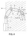
本実施例の事例では制御コンピュータ17は、制御コンピュータないしそこで進行するコンピュータプログラムが、ロボットRの作業領域を制限することができるように施工されている。ロボットRの作業領域とは、作業および移動をするためのロボットRの領域を意味している。ロボットRの作動時には、特にロボットRのすべての軸1〜6が作業領域の内部に存在していなければならない。図3と図4は、制御コンピュータ17により好ましくは信頼度の高い技術で調整されるロボットRの作業領域30の一例を示しており、図3はロボットRおよび作業領域30を示す平面図であり、図4はロボットRおよび作業領域30を示す側面図である。 In the example of this embodiment, the
本実施例の事例では、制御コンピュータ17はロボットRの作業領域30を、現在フランジ18に取り付けられている工具21〜24に合わせて、ないしは現在フランジ18に取り付けられている医療用工具21〜24で実行されるべきアプリケーションのパフォーマンス要求事項に合わせて、動的に充足することが意図されている。 In the case of the present embodiment, the
本実施例の事例において、工具21〜24が現在フランジ18に取り付けられているという情報を制御コンピュータ17が得るために、各々の工具21〜24には、本実施例の事例では受動的なトランスポンダである少なくとも1つのRFIDトランスポンダ25〜28がそれぞれ配置されている。トランスポンダは原理に関して当業者に周知であるので、トランスポンダ25〜28は詳しくは図示されておらず、その機能性についてこれ以上は説明しない。 In the case of the present embodiment, in order for the
本実施例の事例では、各々のトランスポンダ25〜28には、工具21〜24に関する情報を含むデータ31〜34が保存されている。この情報は、たとえば該当する工具21〜24の質量および重心を含んでいる。あるいはこの情報は、工具21〜24の使用ないしは相応の医療用アプリケーションのパフォーマンス要求事項の適用についての指定事項を含むこともでき、たとえば許容される速度プロファイル、許容される加速度プロファイル、あるいは、該当する工具21〜24の使用に基づいてロボットRに求められる剛性などを含むことができる。 In the case of the present embodiment,
さらに本実施例の事例では、ロボットRのフランジ18に、図示しない仕方で制御コンピュータ17と接続された読み取り装置19が取り付けられている。 Further, in the case of the present embodiment, a
ロボットRのフランジ18に工具21〜24のうちの1つが取り付けられると、取付の終了後、読み取り装置19が信号を送信し、この信号は、フランジ18に取り付けられた工具21〜24のトランスポンダ25〜28によって受信される。図1に示す実施例では、工具21はフランジ18にすでに取り付けられており、それを受けて工具21のトランスポンダ25は読み取り装置19から得られた信号を受信し、それに応じて応答信号を自動的に生成して、これを読み取り装置19へ送信する。応答信号は工具21のデータ31を有している。読み取り装置19は、データ31を含む応答信号をトランスポンダ25から受信して、データ31を制御コンピュータ17へ伝送する。データ31の読み取り、ならびに読み取り装置19から制御コンピュータ17へのデータ31の伝送は、たとえばチェックサムを利用して、信頼度の高い技術で行われる。 When one of the
制御コンピュータ17はデータ31を受けとり、工具21のパフォーマンス要求事項、質量、および/または重心に関する情報に基づいて、工具21に割り当てられる作業領域30を判定する。作業領域30の判定は、たとえば計算規則を通じて行われるか、または事前に作成されて制御コンピュータ17に保存される表を通じて行われる。 The
工具21に割り当てられる作業領域30の判定と調整は、たとえば自動式に行うことができる。あるいは、たとえば詳しくは図示しない人物が制御コンピュータ17の操作手段20を操作することによって、トランスポンダ25からのデータ31の読み取りを手動式に開始することも可能である。その追加または代替として、作業領域30の変更を手動式に操作することが意図されていてもよい。 The determination and adjustment of the
同様に、制御コンピュータ17からトランスポンダ25への信頼度の高い逆方向通信路を介して、トランスポンダに信頼度の高い技術で書き込みをすることが可能であり、それにより、たとえば動作時間を記憶させることができる。 Similarly, it is possible to write to the transponder via a reliable reverse communication path from the
作業領域30の調整に必要なデータを、工具に配置されたデータ記憶装置に保存する代わりに、使用する工具21〜24に関する情報を制御コンピュータ17に保存しておくことが意図されていてもよい。このように、この人物は制御コンピュータ17で使用する工具21〜24に関する入力を行うことが可能であり、そのために、たとえば制御コンピュータ17と接続されたスクリーン29によって工具の選択が提供される。そしてこの人物は、たとえば制御コンピュータ17と接続されたコンピュータマウス35でクリックをすることで、該当する工具を選択することができる。すると、選択された工具のパフォーマンス要求事項および該当する荷重パラメータ(質量と重力)が、アプリケーションソフトウェアから制御コンピュータ17へ信頼度の高い技術で、たとえばチェックサムを通じて確認されたうえで、伝送される。こうした情報に基づき、ロボットRの作業領域30が同じく信頼度の高い技術で制限される。同様に、操作員によるコンフィギュレーションも信頼度の高い技術で行われるのが好ましい。 Instead of saving the data necessary for the adjustment of the
工具21〜24ないしそのパフォーマンス要求事項に関する情報が既知でない場合、本実施例の事例では、ロボットRに取り付けられている工具21〜24の質量と重心を次のようにして判定することが意図される:
制御コンピュータ17が電気式の駆動装置11〜16を制御して、軸1〜6が事前設定された位置にくるようにする。図5では、3つの異なる軸位置S1〜S3を示すことによって、その様子が図示されている。次いで、電気式の駆動装置11〜16により印加されるトルクがそれぞれ異なる軸位置S1〜S3について、たとえば駆動装置11〜16の電流の評価によって、またはロボットRに組み込まれた力センサおよび/またはトルクセンサによって判定される。In the case of the present embodiment, when the information about the
The
あるいは、ロボットRがそのフランジ18に取り付けられている工具21を異なる位置へと移動させ、フランジ18に作用する力および/またはトルクから判定をすることも可能である。 Alternatively, the robot R can move the
姿勢の変更(軸位置S1〜S3)およびトルクの判定および/または計算は、いずれも信頼度の高い技術で行われるのが好ましい。そしてこのような情報から、(同様に信頼度の高い技術で)ロボットRに取り付けられている工具の荷重パラメータ(質量と重心)を計算し、それに準じて該当する作業領域30を設定することができる。
It is preferable that the posture change (axial positions S1 to S3) and the torque determination and / or calculation are all performed by a highly reliable technique. From such information, the load parameters (mass and center of gravity) of the tool attached to the robot R are calculated (similarly with a highly reliable technique), and the
Claims (14)
Translated fromJapanese複数の軸と1つの制御装置とを有する前記医療用ロボットの取付装置に医療用工具を取り付ける方法ステップと、
取り付けられている前記医療用工具に対応する所定の作業領域を決定するために、取り付けられている前記医療用工具に関する情報を自動的に判定する方法ステップと、
制御装置により、前記複数の軸が前記所定の作業領域の外部へ動くことを妨げることによって、前記医療用ロボットの作業領域を前記所定の作業領域に制限し、それにより、取り付けられている前記医療用工具を用いることによって実行されるべきアプリケーションのパフォーマンス要求事項を前記医療用ロボットが充足するようにする方法ステップと、を有し、
前記所定の作業領域は、前記医療用ロボットがその機械的な拡張に基づいて動くことができる最大の作業領域のうちの一部であり、前記医療用工具毎に予め定められており、且つ、
前記アプリケーションのパフォーマンス要求事項は、求められる速度能力、求められる加速度能力、前記医療用ロボットに作用する荷重、取り付けられている前記医療用工具の使用に基づいて前記医療用ロボットに求められる剛性、前記医療用ロボットの制動距離、および/または、前記医療用ロボットの操作性を含む、
方法。In a way to meet the performance requirements of medical robots,
A method step of attaching a medical tool to the attachment device of the medical robot having a plurality of axes and a control device;
A method step of automatically determining information about the attached medical tool to determine a predetermined work area corresponding to the attached medical tool;
The control devicerestricts the work area of the medical robot to the predetermined work areaby preventing the plurality of axes from moving outside the predetermined work area, and thereby the attached medical care Having the medical robot meet the performance requirements of an application to be executed by using a tool
Said predetermined work area is part of the largest working area where the medical robot can move on the basis of the mechanical expansion,it is determined in advance for each of the medical tool,and,
The performance requirements of the application include: required speed capability, required acceleration capability, load acting on the medical robot, rigidity required for the medical robot based on use of the attached medical tool, Including the braking distance of the medical robot and / or the operability of the medical robot,
Method.
該データは、取り付けられている前記医療用工具に関する情報および/またはそのパフォーマンス要求事項に関する情報を有しており、
読み取られた前記データに基づいて前記制御装置を自動的に適合化し、それにより該制御装置が前記作業領域を制限する、
請求項1に記載の方法。Having the method steps of reading data from a data carrier located on the medical tool being attached;
The data comprises information regarding the medical tool being installed and / or information regarding its performance requirements;
Automatically adapting the control device based on the read data, whereby the control devicelimits the work area;
The method of claim 1.
取付装置への前記医療用工具の取付後に前記データの読み取りを手動式に開始し、
読み取られた前記データに基づき、および手動式の操作に基づき、前記制御装置を適合化し、それにより該制御装置が前記作業領域を制限し、および/または
データを前記データ担体から前記制御装置へ伝送する、
請求項2または3に記載の方法。In addition,
Manually start reading the data after mounting the medical tool on a mounting device;
Based on the data read and based on manual operation, the control device is adapted so that the control devicelimits the working area and / or transmits data from the data carrier to the control device. Send,
The method according to claim2 or3 .
前記医療用ロボットによって、取り付けられている前記医療用工具をさまざまに異なる位置へ動かし、前記医療用ロボットの軸に作用するトルク、または前記医療用ロボットの駆動装置によるトルクを判定する方法ステップ、または、
前記医療用ロボットによって、取り付けられている前記医療用工具をさまざまに異なる位置へ動かし、前記医療用ロボットの前記取付装置に作用する力および/またはトルクを判定する方法ステップ、
を有する請求項5に記載の方法。In order to determine the load parameter,
By the medical robot, howeverdynamic to different positions in different said medical tool is attached, the torque acting on the shaft of the medical robot or how todetermine the constanttorque by the drive of the medical robot, Step or
Wherein the medical robot, the method mounted the visiblemovement of the medical toolto a variety of different positions and todetermine the constantforce and / or torque acting on the mounting device of the medical robot step,
6. The method of claim5 , comprising:
取り付けられている前記医療用工具は前記医療用ロボットにより特に自動式に可動の医療用器具である、
請求項1から7までのいずれか一項に記載の方法。The attachment device is a flange of the medical robot, and / or the medical tool being attached is a medical instrument that is particularly automatically movable by the medical robot;
The method according to any one of claims 1 to7.
複数の可動の軸および取付装置を備えるロボットアームと、
前記ロボットアームの前記軸を駆動装置によって動かすための制御装置と、を有しており、
前記制御装置は、前記取付装置に取り付けられている医療用工具に関する情報を自動的に判定し、且つ、取り付けられている前記医療用工具に対応する所定の作業領域の外部へ前記複数の軸が動くことを妨げることによって、前記医療用ロボットの作業領域を前記所定の作業領域に制限するようにセットアップされており、それにより、取り付けられている前記医療用工具で実行されるべきアプリケーションのパフォーマンス要求事項を前記医療用ロボットが充足するようになっており、
前記所定の作業領域は、前記医療用ロボットがその機械的な拡張に基づいて動くことができる最大の作業領域のうちの一部であり、前記医療用工具毎に予め定められており、且つ、
前記アプリケーションのパフォーマンス要求事項は、求められる速度能力、求められる加速度能力、前記医療用ロボットに作用する荷重、取り付けられている前記医療用工具の使用に基づいて前記医療用ロボットに求められる剛性、前記医療用ロボットの制動距離、および/または前記医療用ロボットの操作性を含む、
医療用ロボット。In medical robots,
A robot arm comprising a plurality of movable shafts and a mounting device;
A control device for moving the axis of the robot arm by a driving device,
Wherein thecontroller, prior SL automatically determines the information about the medical tool is attached to the mounting device, and,mounted in the predetermined work area of the external corresponding to the medical tool and the plurality of axes by preventing the movement, the working area of the medical robot are set up tolimitthe predetermined working area, whereby the to be performed by the medical tool attached application performance The medical robot meets the requirements,
Said predetermined work area is part of the largest working area where the medical robot can move on the basis of the mechanical expansion,it is determined in advance for each of the medical tool,and,
The performance requirements of the application include: required speed capability, required acceleration capability, load acting on the medical robot, rigidity required for the medical robot based on use of the attached medical tool, Including the braking distance of the medical robot, and / or the operability of the medical robot,
Medical robot.
取り付けられている前記医療用工具をさまざまに異なる位置へ動かし、前記医療用ロボットの前記軸に作用するトルクまたは前記医療用ロボットの前記駆動装置によるトルクを判定するようセットアップされ、或いは、
取り付けられている前記医療用工具をさまざまに異なる位置へ動かし、前記医療用ロボットの前記取付装置に作用する力および/またはトルクを判定するようにセットアップされている、
請求項12に記載の医療用ロボット。In order to determine the load parameter of the medical tool being attached,
Movingthe medical tool attachedto the different positions in the variety, is set up to determine the torque by the drive torque or the medical robot acting on the shaft of the medical robot, or
Movingthe medical tool attachedto the different positions in the variety, the isa force and / or torque acting on the mounting device of the medical robot is set up todetermine the constant,
The medical robot according to claim12 .
Input means for inputting information about the attached medical tool to the control device, and the control device is set up tolimit the work area based on the input information The medical robot according to any one of claims9 to13 .
Applications Claiming Priority (3)
| Application Number | Priority Date | Filing Date | Title |
|---|---|---|---|
| DE102008001664.0ADE102008001664B4 (en) | 2008-05-08 | 2008-05-08 | Medical robot and method for meeting the performance requirement of a medical robot |
| DE102008001664.0 | 2008-05-08 | ||
| PCT/EP2009/055408WO2009135835A1 (en) | 2008-05-08 | 2009-05-05 | Medical robot and method for meeting the performance requirements of a medical robot |
Publications (2)
| Publication Number | Publication Date |
|---|---|
| JP2011519741A JP2011519741A (en) | 2011-07-14 |
| JP5325976B2true JP5325976B2 (en) | 2013-10-23 |
Family
ID=41059725
Family Applications (1)
| Application Number | Title | Priority Date | Filing Date |
|---|---|---|---|
| JP2011507890AActiveJP5325976B2 (en) | 2008-05-08 | 2009-05-05 | Medical robot and method for meeting performance requirements of medical robot |
Country Status (7)
| Country | Link |
|---|---|
| US (1) | US8831779B2 (en) |
| EP (1) | EP2271466B1 (en) |
| JP (1) | JP5325976B2 (en) |
| KR (1) | KR20110007193A (en) |
| AT (1) | ATE539852T1 (en) |
| DE (1) | DE102008001664B4 (en) |
| WO (1) | WO2009135835A1 (en) |
Families Citing this family (398)
| Publication number | Priority date | Publication date | Assignee | Title |
|---|---|---|---|---|
| US20070084897A1 (en) | 2003-05-20 | 2007-04-19 | Shelton Frederick E Iv | Articulating surgical stapling instrument incorporating a two-piece e-beam firing mechanism |
| US9060770B2 (en) | 2003-05-20 | 2015-06-23 | Ethicon Endo-Surgery, Inc. | Robotically-driven surgical instrument with E-beam driver |
| US11890012B2 (en) | 2004-07-28 | 2024-02-06 | Cilag Gmbh International | Staple cartridge comprising cartridge body and attached support |
| US8215531B2 (en) | 2004-07-28 | 2012-07-10 | Ethicon Endo-Surgery, Inc. | Surgical stapling instrument having a medical substance dispenser |
| US11998198B2 (en) | 2004-07-28 | 2024-06-04 | Cilag Gmbh International | Surgical stapling instrument incorporating a two-piece E-beam firing mechanism |
| US9072535B2 (en) | 2011-05-27 | 2015-07-07 | Ethicon Endo-Surgery, Inc. | Surgical stapling instruments with rotatable staple deployment arrangements |
| US11484312B2 (en) | 2005-08-31 | 2022-11-01 | Cilag Gmbh International | Staple cartridge comprising a staple driver arrangement |
| US11246590B2 (en) | 2005-08-31 | 2022-02-15 | Cilag Gmbh International | Staple cartridge including staple drivers having different unfired heights |
| US7934630B2 (en) | 2005-08-31 | 2011-05-03 | Ethicon Endo-Surgery, Inc. | Staple cartridges for forming staples having differing formed staple heights |
| US9237891B2 (en) | 2005-08-31 | 2016-01-19 | Ethicon Endo-Surgery, Inc. | Robotically-controlled surgical stapling devices that produce formed staples having different lengths |
| US10159482B2 (en) | 2005-08-31 | 2018-12-25 | Ethicon Llc | Fastener cartridge assembly comprising a fixed anvil and different staple heights |
| US7669746B2 (en) | 2005-08-31 | 2010-03-02 | Ethicon Endo-Surgery, Inc. | Staple cartridges for forming staples having differing formed staple heights |
| US20070106317A1 (en) | 2005-11-09 | 2007-05-10 | Shelton Frederick E Iv | Hydraulically and electrically actuated articulation joints for surgical instruments |
| US20110295295A1 (en) | 2006-01-31 | 2011-12-01 | Ethicon Endo-Surgery, Inc. | Robotically-controlled surgical instrument having recording capabilities |
| US11278279B2 (en) | 2006-01-31 | 2022-03-22 | Cilag Gmbh International | Surgical instrument assembly |
| US20120292367A1 (en) | 2006-01-31 | 2012-11-22 | Ethicon Endo-Surgery, Inc. | Robotically-controlled end effector |
| US7753904B2 (en) | 2006-01-31 | 2010-07-13 | Ethicon Endo-Surgery, Inc. | Endoscopic surgical instrument with a handle that can articulate with respect to the shaft |
| US7845537B2 (en) | 2006-01-31 | 2010-12-07 | Ethicon Endo-Surgery, Inc. | Surgical instrument having recording capabilities |
| US11224427B2 (en) | 2006-01-31 | 2022-01-18 | Cilag Gmbh International | Surgical stapling system including a console and retraction assembly |
| US11793518B2 (en) | 2006-01-31 | 2023-10-24 | Cilag Gmbh International | Powered surgical instruments with firing system lockout arrangements |
| US8708213B2 (en) | 2006-01-31 | 2014-04-29 | Ethicon Endo-Surgery, Inc. | Surgical instrument having a feedback system |
| US8186555B2 (en) | 2006-01-31 | 2012-05-29 | Ethicon Endo-Surgery, Inc. | Motor-driven surgical cutting and fastening instrument with mechanical closure system |
| US20110024477A1 (en) | 2009-02-06 | 2011-02-03 | Hall Steven G | Driven Surgical Stapler Improvements |
| US8820603B2 (en) | 2006-01-31 | 2014-09-02 | Ethicon Endo-Surgery, Inc. | Accessing data stored in a memory of a surgical instrument |
| US8992422B2 (en) | 2006-03-23 | 2015-03-31 | Ethicon Endo-Surgery, Inc. | Robotically-controlled endoscopic accessory channel |
| US8322455B2 (en) | 2006-06-27 | 2012-12-04 | Ethicon Endo-Surgery, Inc. | Manually driven surgical cutting and fastening instrument |
| US10568652B2 (en) | 2006-09-29 | 2020-02-25 | Ethicon Llc | Surgical staples having attached drivers of different heights and stapling instruments for deploying the same |
| US11980366B2 (en) | 2006-10-03 | 2024-05-14 | Cilag Gmbh International | Surgical instrument |
| US11291441B2 (en) | 2007-01-10 | 2022-04-05 | Cilag Gmbh International | Surgical instrument with wireless communication between control unit and remote sensor |
| US8684253B2 (en) | 2007-01-10 | 2014-04-01 | Ethicon Endo-Surgery, Inc. | Surgical instrument with wireless communication between a control unit of a robotic system and remote sensor |
| US8632535B2 (en) | 2007-01-10 | 2014-01-21 | Ethicon Endo-Surgery, Inc. | Interlock and surgical instrument including same |
| US11039836B2 (en) | 2007-01-11 | 2021-06-22 | Cilag Gmbh International | Staple cartridge for use with a surgical stapling instrument |
| US20080169333A1 (en) | 2007-01-11 | 2008-07-17 | Shelton Frederick E | Surgical stapler end effector with tapered distal end |
| US7673782B2 (en) | 2007-03-15 | 2010-03-09 | Ethicon Endo-Surgery, Inc. | Surgical stapling instrument having a releasable buttress material |
| US8931682B2 (en) | 2007-06-04 | 2015-01-13 | Ethicon Endo-Surgery, Inc. | Robotically-controlled shaft based rotary drive systems for surgical instruments |
| US11564682B2 (en) | 2007-06-04 | 2023-01-31 | Cilag Gmbh International | Surgical stapler device |
| US7753245B2 (en) | 2007-06-22 | 2010-07-13 | Ethicon Endo-Surgery, Inc. | Surgical stapling instruments |
| US11849941B2 (en) | 2007-06-29 | 2023-12-26 | Cilag Gmbh International | Staple cartridge having staple cavities extending at a transverse angle relative to a longitudinal cartridge axis |
| US7866527B2 (en) | 2008-02-14 | 2011-01-11 | Ethicon Endo-Surgery, Inc. | Surgical stapling apparatus with interlockable firing system |
| US8758391B2 (en) | 2008-02-14 | 2014-06-24 | Ethicon Endo-Surgery, Inc. | Interchangeable tools for surgical instruments |
| US8573465B2 (en) | 2008-02-14 | 2013-11-05 | Ethicon Endo-Surgery, Inc. | Robotically-controlled surgical end effector system with rotary actuated closure systems |
| US9179912B2 (en) | 2008-02-14 | 2015-11-10 | Ethicon Endo-Surgery, Inc. | Robotically-controlled motorized surgical cutting and fastening instrument |
| US7819298B2 (en) | 2008-02-14 | 2010-10-26 | Ethicon Endo-Surgery, Inc. | Surgical stapling apparatus with control features operable with one hand |
| US11986183B2 (en) | 2008-02-14 | 2024-05-21 | Cilag Gmbh International | Surgical cutting and fastening instrument comprising a plurality of sensors to measure an electrical parameter |
| JP5410110B2 (en) | 2008-02-14 | 2014-02-05 | エシコン・エンド−サージェリィ・インコーポレイテッド | Surgical cutting / fixing instrument with RF electrode |
| US8636736B2 (en) | 2008-02-14 | 2014-01-28 | Ethicon Endo-Surgery, Inc. | Motorized surgical cutting and fastening instrument |
| US9585657B2 (en) | 2008-02-15 | 2017-03-07 | Ethicon Endo-Surgery, Llc | Actuator for releasing a layer of material from a surgical end effector |
| US9005230B2 (en) | 2008-09-23 | 2015-04-14 | Ethicon Endo-Surgery, Inc. | Motorized surgical instrument |
| US8210411B2 (en) | 2008-09-23 | 2012-07-03 | Ethicon Endo-Surgery, Inc. | Motor-driven surgical cutting instrument |
| US9386983B2 (en) | 2008-09-23 | 2016-07-12 | Ethicon Endo-Surgery, Llc | Robotically-controlled motorized surgical instrument |
| US11648005B2 (en) | 2008-09-23 | 2023-05-16 | Cilag Gmbh International | Robotically-controlled motorized surgical instrument with an end effector |
| US8608045B2 (en) | 2008-10-10 | 2013-12-17 | Ethicon Endo-Sugery, Inc. | Powered surgical cutting and stapling apparatus with manually retractable firing system |
| US8517239B2 (en) | 2009-02-05 | 2013-08-27 | Ethicon Endo-Surgery, Inc. | Surgical stapling instrument comprising a magnetic element driver |
| RU2525225C2 (en) | 2009-02-06 | 2014-08-10 | Этикон Эндо-Серджери, Инк. | Improvement of drive surgical suturing instrument |
| US11090104B2 (en) | 2009-10-09 | 2021-08-17 | Cilag Gmbh International | Surgical generator for ultrasonic and electrosurgical devices |
| US8851354B2 (en) | 2009-12-24 | 2014-10-07 | Ethicon Endo-Surgery, Inc. | Surgical cutting instrument that analyzes tissue thickness |
| US8220688B2 (en) | 2009-12-24 | 2012-07-17 | Ethicon Endo-Surgery, Inc. | Motor-driven surgical cutting instrument with electric actuator directional control assembly |
| US8783543B2 (en) | 2010-07-30 | 2014-07-22 | Ethicon Endo-Surgery, Inc. | Tissue acquisition arrangements and methods for surgical stapling devices |
| US9386988B2 (en) | 2010-09-30 | 2016-07-12 | Ethicon End-Surgery, LLC | Retainer assembly including a tissue thickness compensator |
| US12213666B2 (en) | 2010-09-30 | 2025-02-04 | Cilag Gmbh International | Tissue thickness compensator comprising layers |
| US11925354B2 (en) | 2010-09-30 | 2024-03-12 | Cilag Gmbh International | Staple cartridge comprising staples positioned within a compressible portion thereof |
| US9788834B2 (en) | 2010-09-30 | 2017-10-17 | Ethicon Llc | Layer comprising deployable attachment members |
| US10945731B2 (en) | 2010-09-30 | 2021-03-16 | Ethicon Llc | Tissue thickness compensator comprising controlled release and expansion |
| US11298125B2 (en) | 2010-09-30 | 2022-04-12 | Cilag Gmbh International | Tissue stapler having a thickness compensator |
| US9351730B2 (en) | 2011-04-29 | 2016-05-31 | Ethicon Endo-Surgery, Llc | Tissue thickness compensator comprising channels |
| US9016542B2 (en) | 2010-09-30 | 2015-04-28 | Ethicon Endo-Surgery, Inc. | Staple cartridge comprising compressible distortion resistant components |
| US9629814B2 (en) | 2010-09-30 | 2017-04-25 | Ethicon Endo-Surgery, Llc | Tissue thickness compensator configured to redistribute compressive forces |
| US11812965B2 (en) | 2010-09-30 | 2023-11-14 | Cilag Gmbh International | Layer of material for a surgical end effector |
| US8695866B2 (en) | 2010-10-01 | 2014-04-15 | Ethicon Endo-Surgery, Inc. | Surgical instrument having a power control circuit |
| JP5839929B2 (en)* | 2010-11-19 | 2016-01-06 | キヤノン株式会社 | Information processing apparatus, information processing system, information processing method, and program |
| WO2012074564A1 (en) | 2010-12-02 | 2012-06-07 | Freehand Endoscopic Devices, Inc. | Surgical tool |
| US9119655B2 (en) | 2012-08-03 | 2015-09-01 | Stryker Corporation | Surgical manipulator capable of controlling a surgical instrument in multiple modes |
| US9921712B2 (en) | 2010-12-29 | 2018-03-20 | Mako Surgical Corp. | System and method for providing substantially stable control of a surgical tool |
| DE102011008856A1 (en)* | 2011-01-18 | 2012-07-19 | Fresenius Medical Care Deutschland Gmbh | Method for carrying out a query of a specification feature of a medical-technical functional device, medical-technical functional device, medical-technical treatment device and control device |
| AU2012250197B2 (en) | 2011-04-29 | 2017-08-10 | Ethicon Endo-Surgery, Inc. | Staple cartridge comprising staples positioned within a compressible portion thereof |
| US11207064B2 (en) | 2011-05-27 | 2021-12-28 | Cilag Gmbh International | Automated end effector component reloading system for use with a robotic system |
| US9437005B2 (en)* | 2011-07-08 | 2016-09-06 | Canon Kabushiki Kaisha | Information processing apparatus and information processing method |
| EP2737375B1 (en)* | 2011-07-27 | 2016-11-16 | ABB Schweiz AG | System for commanding a robot |
| JP6224070B2 (en) | 2012-03-28 | 2017-11-01 | エシコン・エンド−サージェリィ・インコーポレイテッドEthicon Endo−Surgery,Inc. | Retainer assembly including tissue thickness compensator |
| BR112014024098B1 (en) | 2012-03-28 | 2021-05-25 | Ethicon Endo-Surgery, Inc. | staple cartridge |
| MX358135B (en) | 2012-03-28 | 2018-08-06 | Ethicon Endo Surgery Inc | Tissue thickness compensator comprising a plurality of layers. |
| US9101358B2 (en) | 2012-06-15 | 2015-08-11 | Ethicon Endo-Surgery, Inc. | Articulatable surgical instrument comprising a firing drive |
| US11278284B2 (en) | 2012-06-28 | 2022-03-22 | Cilag Gmbh International | Rotary drive arrangements for surgical instruments |
| JP6290201B2 (en) | 2012-06-28 | 2018-03-07 | エシコン・エンド−サージェリィ・インコーポレイテッドEthicon Endo−Surgery,Inc. | Lockout for empty clip cartridge |
| US20140001231A1 (en) | 2012-06-28 | 2014-01-02 | Ethicon Endo-Surgery, Inc. | Firing system lockout arrangements for surgical instruments |
| BR112014032776B1 (en) | 2012-06-28 | 2021-09-08 | Ethicon Endo-Surgery, Inc | SURGICAL INSTRUMENT SYSTEM AND SURGICAL KIT FOR USE WITH A SURGICAL INSTRUMENT SYSTEM |
| US9408606B2 (en) | 2012-06-28 | 2016-08-09 | Ethicon Endo-Surgery, Llc | Robotically powered surgical device with manually-actuatable reversing system |
| US9282974B2 (en) | 2012-06-28 | 2016-03-15 | Ethicon Endo-Surgery, Llc | Empty clip cartridge lockout |
| US9289256B2 (en) | 2012-06-28 | 2016-03-22 | Ethicon Endo-Surgery, Llc | Surgical end effectors having angled tissue-contacting surfaces |
| US12383267B2 (en) | 2012-06-28 | 2025-08-12 | Cilag Gmbh International | Robotically powered surgical device with manually-actuatable reversing system |
| CN107198567B (en) | 2012-08-03 | 2021-02-09 | 史赛克公司 | Systems and methods for robotic surgery |
| US9820818B2 (en) | 2012-08-03 | 2017-11-21 | Stryker Corporation | System and method for controlling a surgical manipulator based on implant parameters |
| US9226796B2 (en) | 2012-08-03 | 2016-01-05 | Stryker Corporation | Method for detecting a disturbance as an energy applicator of a surgical instrument traverses a cutting path |
| WO2014043702A1 (en) | 2012-09-17 | 2014-03-20 | Rethink Robotics, Inc. | Constraining robotic manipulators with redundant degrees of freedom |
| JP2014140913A (en)* | 2013-01-22 | 2014-08-07 | Jtekt Corp | Robot control device, robot control system, and robot control method |
| BR112015021082B1 (en) | 2013-03-01 | 2022-05-10 | Ethicon Endo-Surgery, Inc | surgical instrument |
| RU2672520C2 (en) | 2013-03-01 | 2018-11-15 | Этикон Эндо-Серджери, Инк. | Hingedly turnable surgical instruments with conducting ways for signal transfer |
| US9808244B2 (en) | 2013-03-14 | 2017-11-07 | Ethicon Llc | Sensor arrangements for absolute positioning system for surgical instruments |
| US9629629B2 (en) | 2013-03-14 | 2017-04-25 | Ethicon Endo-Surgey, LLC | Control systems for surgical instruments |
| US9826976B2 (en) | 2013-04-16 | 2017-11-28 | Ethicon Llc | Motor driven surgical instruments with lockable dual drive shafts |
| BR112015026109B1 (en) | 2013-04-16 | 2022-02-22 | Ethicon Endo-Surgery, Inc | surgical instrument |
| MX369362B (en) | 2013-08-23 | 2019-11-06 | Ethicon Endo Surgery Llc | Firing member retraction devices for powered surgical instruments. |
| US9775609B2 (en) | 2013-08-23 | 2017-10-03 | Ethicon Llc | Tamper proof circuit for surgical instrument battery pack |
| US9962161B2 (en) | 2014-02-12 | 2018-05-08 | Ethicon Llc | Deliverable surgical instrument |
| US12232723B2 (en) | 2014-03-26 | 2025-02-25 | Cilag Gmbh International | Systems and methods for controlling a segmented circuit |
| US20150272580A1 (en) | 2014-03-26 | 2015-10-01 | Ethicon Endo-Surgery, Inc. | Verification of number of battery exchanges/procedure count |
| US10004497B2 (en) | 2014-03-26 | 2018-06-26 | Ethicon Llc | Interface systems for use with surgical instruments |
| US10013049B2 (en) | 2014-03-26 | 2018-07-03 | Ethicon Llc | Power management through sleep options of segmented circuit and wake up control |
| BR112016021943B1 (en) | 2014-03-26 | 2022-06-14 | Ethicon Endo-Surgery, Llc | SURGICAL INSTRUMENT FOR USE BY AN OPERATOR IN A SURGICAL PROCEDURE |
| BR112016023825B1 (en) | 2014-04-16 | 2022-08-02 | Ethicon Endo-Surgery, Llc | STAPLE CARTRIDGE FOR USE WITH A SURGICAL STAPLER AND STAPLE CARTRIDGE FOR USE WITH A SURGICAL INSTRUMENT |
| US10470768B2 (en) | 2014-04-16 | 2019-11-12 | Ethicon Llc | Fastener cartridge including a layer attached thereto |
| CN106456176B (en) | 2014-04-16 | 2019-06-28 | 伊西康内外科有限责任公司 | Fastener Cartridge Including Extensions With Different Configurations |
| US20150297225A1 (en) | 2014-04-16 | 2015-10-22 | Ethicon Endo-Surgery, Inc. | Fastener cartridges including extensions having different configurations |
| CN106456159B (en) | 2014-04-16 | 2019-03-08 | 伊西康内外科有限责任公司 | Fastener Cartridge Assembly and Nail Retainer Cover Arrangement |
| US10327764B2 (en) | 2014-09-26 | 2019-06-25 | Ethicon Llc | Method for creating a flexible staple line |
| NL2013369B1 (en)* | 2014-08-26 | 2016-09-26 | Univ Eindhoven Tech | Surgical robotic system and control of surgical robotic system. |
| BR112017004361B1 (en) | 2014-09-05 | 2023-04-11 | Ethicon Llc | ELECTRONIC SYSTEM FOR A SURGICAL INSTRUMENT |
| US10135242B2 (en) | 2014-09-05 | 2018-11-20 | Ethicon Llc | Smart cartridge wake up operation and data retention |
| US11311294B2 (en) | 2014-09-05 | 2022-04-26 | Cilag Gmbh International | Powered medical device including measurement of closure state of jaws |
| US10105142B2 (en) | 2014-09-18 | 2018-10-23 | Ethicon Llc | Surgical stapler with plurality of cutting elements |
| CN107427300B (en) | 2014-09-26 | 2020-12-04 | 伊西康有限责任公司 | Surgical suture buttresses and auxiliary materials |
| US11523821B2 (en) | 2014-09-26 | 2022-12-13 | Cilag Gmbh International | Method for creating a flexible staple line |
| US9924944B2 (en) | 2014-10-16 | 2018-03-27 | Ethicon Llc | Staple cartridge comprising an adjunct material |
| JP5896003B1 (en)* | 2014-10-29 | 2016-03-30 | 株式会社安川電機 | Processing apparatus, teaching method, workpiece production method, controller, and control method |
| JP2016087705A (en)* | 2014-10-29 | 2016-05-23 | 株式会社安川電機 | Processing device and work production method |
| US10517594B2 (en) | 2014-10-29 | 2019-12-31 | Ethicon Llc | Cartridge assemblies for surgical staplers |
| US11141153B2 (en) | 2014-10-29 | 2021-10-12 | Cilag Gmbh International | Staple cartridges comprising driver arrangements |
| WO2016067689A1 (en) | 2014-10-29 | 2016-05-06 | 株式会社安川電機 | Machining device and production method of workpiece |
| US9844376B2 (en) | 2014-11-06 | 2017-12-19 | Ethicon Llc | Staple cartridge comprising a releasable adjunct material |
| US10736636B2 (en) | 2014-12-10 | 2020-08-11 | Ethicon Llc | Articulatable surgical instrument system |
| MX389118B (en) | 2014-12-18 | 2025-03-20 | Ethicon Llc | SURGICAL INSTRUMENT WITH AN ANVIL THAT CAN BE SELECTIVELY MOVED ON A DISCRETE, NON-MOBILE AXIS RELATIVE TO A STAPLE CARTRIDGE. |
| US10085748B2 (en) | 2014-12-18 | 2018-10-02 | Ethicon Llc | Locking arrangements for detachable shaft assemblies with articulatable surgical end effectors |
| US9943309B2 (en) | 2014-12-18 | 2018-04-17 | Ethicon Llc | Surgical instruments with articulatable end effectors and movable firing beam support arrangements |
| US9844375B2 (en) | 2014-12-18 | 2017-12-19 | Ethicon Llc | Drive arrangements for articulatable surgical instruments |
| US9844374B2 (en) | 2014-12-18 | 2017-12-19 | Ethicon Llc | Surgical instrument systems comprising an articulatable end effector and means for adjusting the firing stroke of a firing member |
| US9987000B2 (en) | 2014-12-18 | 2018-06-05 | Ethicon Llc | Surgical instrument assembly comprising a flexible articulation system |
| US11154301B2 (en) | 2015-02-27 | 2021-10-26 | Cilag Gmbh International | Modular stapling assembly |
| JP5975129B1 (en) | 2015-03-02 | 2016-08-23 | 株式会社安川電機 | robot |
| US10441279B2 (en) | 2015-03-06 | 2019-10-15 | Ethicon Llc | Multiple level thresholds to modify operation of powered surgical instruments |
| US9901342B2 (en) | 2015-03-06 | 2018-02-27 | Ethicon Endo-Surgery, Llc | Signal and power communication system positioned on a rotatable shaft |
| US9993248B2 (en) | 2015-03-06 | 2018-06-12 | Ethicon Endo-Surgery, Llc | Smart sensors with local signal processing |
| US10548504B2 (en) | 2015-03-06 | 2020-02-04 | Ethicon Llc | Overlaid multi sensor radio frequency (RF) electrode system to measure tissue compression |
| JP2020121162A (en) | 2015-03-06 | 2020-08-13 | エシコン エルエルシーEthicon LLC | Time dependent evaluation of sensor data to determine stability element, creep element and viscoelastic element of measurement |
| US10245033B2 (en) | 2015-03-06 | 2019-04-02 | Ethicon Llc | Surgical instrument comprising a lockable battery housing |
| US10433844B2 (en) | 2015-03-31 | 2019-10-08 | Ethicon Llc | Surgical instrument with selectively disengageable threaded drive systems |
| JP6464945B2 (en)* | 2015-07-03 | 2019-02-06 | 株式会社デンソーウェーブ | Robot system |
| US10835249B2 (en) | 2015-08-17 | 2020-11-17 | Ethicon Llc | Implantable layers for a surgical instrument |
| US10238386B2 (en) | 2015-09-23 | 2019-03-26 | Ethicon Llc | Surgical stapler having motor control based on an electrical parameter related to a motor current |
| US10105139B2 (en) | 2015-09-23 | 2018-10-23 | Ethicon Llc | Surgical stapler having downstream current-based motor control |
| US10299878B2 (en) | 2015-09-25 | 2019-05-28 | Ethicon Llc | Implantable adjunct systems for determining adjunct skew |
| US10478188B2 (en) | 2015-09-30 | 2019-11-19 | Ethicon Llc | Implantable layer comprising a constricted configuration |
| US11890015B2 (en) | 2015-09-30 | 2024-02-06 | Cilag Gmbh International | Compressible adjunct with crossing spacer fibers |
| US10433846B2 (en) | 2015-09-30 | 2019-10-08 | Ethicon Llc | Compressible adjunct with crossing spacer fibers |
| US10980539B2 (en) | 2015-09-30 | 2021-04-20 | Ethicon Llc | Implantable adjunct comprising bonded layers |
| US10292704B2 (en) | 2015-12-30 | 2019-05-21 | Ethicon Llc | Mechanisms for compensating for battery pack failure in powered surgical instruments |
| US10265068B2 (en) | 2015-12-30 | 2019-04-23 | Ethicon Llc | Surgical instruments with separable motors and motor control circuits |
| US10368865B2 (en) | 2015-12-30 | 2019-08-06 | Ethicon Llc | Mechanisms for compensating for drivetrain failure in powered surgical instruments |
| US11129670B2 (en) | 2016-01-15 | 2021-09-28 | Cilag Gmbh International | Modular battery powered handheld surgical instrument with selective application of energy based on button displacement, intensity, or local tissue characterization |
| US11051840B2 (en) | 2016-01-15 | 2021-07-06 | Ethicon Llc | Modular battery powered handheld surgical instrument with reusable asymmetric handle housing |
| BR112018016098B1 (en) | 2016-02-09 | 2023-02-23 | Ethicon Llc | SURGICAL INSTRUMENT |
| US11213293B2 (en) | 2016-02-09 | 2022-01-04 | Cilag Gmbh International | Articulatable surgical instruments with single articulation link arrangements |
| US10448948B2 (en) | 2016-02-12 | 2019-10-22 | Ethicon Llc | Mechanisms for compensating for drivetrain failure in powered surgical instruments |
| US11224426B2 (en) | 2016-02-12 | 2022-01-18 | Cilag Gmbh International | Mechanisms for compensating for drivetrain failure in powered surgical instruments |
| US11607239B2 (en) | 2016-04-15 | 2023-03-21 | Cilag Gmbh International | Systems and methods for controlling a surgical stapling and cutting instrument |
| US11179150B2 (en) | 2016-04-15 | 2021-11-23 | Cilag Gmbh International | Systems and methods for controlling a surgical stapling and cutting instrument |
| US10426467B2 (en) | 2016-04-15 | 2019-10-01 | Ethicon Llc | Surgical instrument with detection sensors |
| US10357247B2 (en) | 2016-04-15 | 2019-07-23 | Ethicon Llc | Surgical instrument with multiple program responses during a firing motion |
| US10335145B2 (en) | 2016-04-15 | 2019-07-02 | Ethicon Llc | Modular surgical instrument with configurable operating mode |
| US10456137B2 (en) | 2016-04-15 | 2019-10-29 | Ethicon Llc | Staple formation detection mechanisms |
| US10828028B2 (en) | 2016-04-15 | 2020-11-10 | Ethicon Llc | Surgical instrument with multiple program responses during a firing motion |
| US10492783B2 (en) | 2016-04-15 | 2019-12-03 | Ethicon, Llc | Surgical instrument with improved stop/start control during a firing motion |
| US10363037B2 (en) | 2016-04-18 | 2019-07-30 | Ethicon Llc | Surgical instrument system comprising a magnetic lockout |
| US20170296173A1 (en) | 2016-04-18 | 2017-10-19 | Ethicon Endo-Surgery, Llc | Method for operating a surgical instrument |
| US11317917B2 (en) | 2016-04-18 | 2022-05-03 | Cilag Gmbh International | Surgical stapling system comprising a lockable firing assembly |
| US10500000B2 (en) | 2016-08-16 | 2019-12-10 | Ethicon Llc | Surgical tool with manual control of end effector jaws |
| US11266430B2 (en) | 2016-11-29 | 2022-03-08 | Cilag Gmbh International | End effector control and calibration |
| US11202682B2 (en) | 2016-12-16 | 2021-12-21 | Mako Surgical Corp. | Techniques for modifying tool operation in a surgical robotic system based on comparing actual and commanded states of the tool relative to a surgical site |
| US10813638B2 (en) | 2016-12-21 | 2020-10-27 | Ethicon Llc | Surgical end effectors with expandable tissue stop arrangements |
| US10542982B2 (en) | 2016-12-21 | 2020-01-28 | Ethicon Llc | Shaft assembly comprising first and second articulation lockouts |
| US10898186B2 (en) | 2016-12-21 | 2021-01-26 | Ethicon Llc | Staple forming pocket arrangements comprising primary sidewalls and pocket sidewalls |
| US10582928B2 (en) | 2016-12-21 | 2020-03-10 | Ethicon Llc | Articulation lock arrangements for locking an end effector in an articulated position in response to actuation of a jaw closure system |
| US10973516B2 (en) | 2016-12-21 | 2021-04-13 | Ethicon Llc | Surgical end effectors and adaptable firing members therefor |
| JP7010956B2 (en) | 2016-12-21 | 2022-01-26 | エシコン エルエルシー | How to staple tissue |
| CN110087565A (en) | 2016-12-21 | 2019-08-02 | 爱惜康有限责任公司 | Surgical stapling system |
| US11134942B2 (en) | 2016-12-21 | 2021-10-05 | Cilag Gmbh International | Surgical stapling instruments and staple-forming anvils |
| US10568625B2 (en) | 2016-12-21 | 2020-02-25 | Ethicon Llc | Staple cartridges and arrangements of staples and staple cavities therein |
| JP2020501815A (en) | 2016-12-21 | 2020-01-23 | エシコン エルエルシーEthicon LLC | Surgical stapling system |
| MX2019007295A (en) | 2016-12-21 | 2019-10-15 | Ethicon Llc | Surgical instrument system comprising an end effector lockout and a firing assembly lockout. |
| US10980536B2 (en) | 2016-12-21 | 2021-04-20 | Ethicon Llc | No-cartridge and spent cartridge lockout arrangements for surgical staplers |
| US20180168615A1 (en) | 2016-12-21 | 2018-06-21 | Ethicon Endo-Surgery, Llc | Method of deforming staples from two different types of staple cartridges with the same surgical stapling instrument |
| JP6983893B2 (en) | 2016-12-21 | 2021-12-17 | エシコン エルエルシーEthicon LLC | Lockout configuration for surgical end effectors and replaceable tool assemblies |
| JP7010957B2 (en) | 2016-12-21 | 2022-01-26 | エシコン エルエルシー | Shaft assembly with lockout |
| US20180168625A1 (en) | 2016-12-21 | 2018-06-21 | Ethicon Endo-Surgery, Llc | Surgical stapling instruments with smart staple cartridges |
| US11090048B2 (en) | 2016-12-21 | 2021-08-17 | Cilag Gmbh International | Method for resetting a fuse of a surgical instrument shaft |
| US10485543B2 (en) | 2016-12-21 | 2019-11-26 | Ethicon Llc | Anvil having a knife slot width |
| US11419606B2 (en) | 2016-12-21 | 2022-08-23 | Cilag Gmbh International | Shaft assembly comprising a clutch configured to adapt the output of a rotary firing member to two different systems |
| USD879809S1 (en) | 2017-06-20 | 2020-03-31 | Ethicon Llc | Display panel with changeable graphical user interface |
| US10881399B2 (en) | 2017-06-20 | 2021-01-05 | Ethicon Llc | Techniques for adaptive control of motor velocity of a surgical stapling and cutting instrument |
| US10980537B2 (en) | 2017-06-20 | 2021-04-20 | Ethicon Llc | Closed loop feedback control of motor velocity of a surgical stapling and cutting instrument based on measured time over a specified number of shaft rotations |
| US10779820B2 (en) | 2017-06-20 | 2020-09-22 | Ethicon Llc | Systems and methods for controlling motor speed according to user input for a surgical instrument |
| US11090046B2 (en) | 2017-06-20 | 2021-08-17 | Cilag Gmbh International | Systems and methods for controlling displacement member motion of a surgical stapling and cutting instrument |
| US11071554B2 (en) | 2017-06-20 | 2021-07-27 | Cilag Gmbh International | Closed loop feedback control of motor velocity of a surgical stapling and cutting instrument based on magnitude of velocity error measurements |
| US10307170B2 (en) | 2017-06-20 | 2019-06-04 | Ethicon Llc | Method for closed loop control of motor velocity of a surgical stapling and cutting instrument |
| US11382638B2 (en) | 2017-06-20 | 2022-07-12 | Cilag Gmbh International | Closed loop feedback control of motor velocity of a surgical stapling and cutting instrument based on measured time over a specified displacement distance |
| US10888321B2 (en) | 2017-06-20 | 2021-01-12 | Ethicon Llc | Systems and methods for controlling velocity of a displacement member of a surgical stapling and cutting instrument |
| US11653914B2 (en) | 2017-06-20 | 2023-05-23 | Cilag Gmbh International | Systems and methods for controlling motor velocity of a surgical stapling and cutting instrument according to articulation angle of end effector |
| US11517325B2 (en) | 2017-06-20 | 2022-12-06 | Cilag Gmbh International | Closed loop feedback control of motor velocity of a surgical stapling and cutting instrument based on measured displacement distance traveled over a specified time interval |
| US11266405B2 (en) | 2017-06-27 | 2022-03-08 | Cilag Gmbh International | Surgical anvil manufacturing methods |
| US11090049B2 (en) | 2017-06-27 | 2021-08-17 | Cilag Gmbh International | Staple forming pocket arrangements |
| US10993716B2 (en) | 2017-06-27 | 2021-05-04 | Ethicon Llc | Surgical anvil arrangements |
| US11324503B2 (en) | 2017-06-27 | 2022-05-10 | Cilag Gmbh International | Surgical firing member arrangements |
| US11564686B2 (en) | 2017-06-28 | 2023-01-31 | Cilag Gmbh International | Surgical shaft assemblies with flexible interfaces |
| US11246592B2 (en) | 2017-06-28 | 2022-02-15 | Cilag Gmbh International | Surgical instrument comprising an articulation system lockable to a frame |
| US10758232B2 (en) | 2017-06-28 | 2020-09-01 | Ethicon Llc | Surgical instrument with positive jaw opening features |
| US11484310B2 (en) | 2017-06-28 | 2022-11-01 | Cilag Gmbh International | Surgical instrument comprising a shaft including a closure tube profile |
| US10903685B2 (en) | 2017-06-28 | 2021-01-26 | Ethicon Llc | Surgical shaft assemblies with slip ring assemblies forming capacitive channels |
| US11259805B2 (en) | 2017-06-28 | 2022-03-01 | Cilag Gmbh International | Surgical instrument comprising firing member supports |
| EP3420947B1 (en) | 2017-06-28 | 2022-05-25 | Cilag GmbH International | Surgical instrument comprising selectively actuatable rotatable couplers |
| US10765427B2 (en) | 2017-06-28 | 2020-09-08 | Ethicon Llc | Method for articulating a surgical instrument |
| USD906355S1 (en) | 2017-06-28 | 2020-12-29 | Ethicon Llc | Display screen or portion thereof with a graphical user interface for a surgical instrument |
| US10932772B2 (en) | 2017-06-29 | 2021-03-02 | Ethicon Llc | Methods for closed loop velocity control for robotic surgical instrument |
| US11304695B2 (en) | 2017-08-03 | 2022-04-19 | Cilag Gmbh International | Surgical system shaft interconnection |
| US11944300B2 (en) | 2017-08-03 | 2024-04-02 | Cilag Gmbh International | Method for operating a surgical system bailout |
| US11471155B2 (en) | 2017-08-03 | 2022-10-18 | Cilag Gmbh International | Surgical system bailout |
| US11974742B2 (en) | 2017-08-03 | 2024-05-07 | Cilag Gmbh International | Surgical system comprising an articulation bailout |
| USD917500S1 (en) | 2017-09-29 | 2021-04-27 | Ethicon Llc | Display screen or portion thereof with graphical user interface |
| USD907647S1 (en) | 2017-09-29 | 2021-01-12 | Ethicon Llc | Display screen or portion thereof with animated graphical user interface |
| US11399829B2 (en) | 2017-09-29 | 2022-08-02 | Cilag Gmbh International | Systems and methods of initiating a power shutdown mode for a surgical instrument |
| USD907648S1 (en) | 2017-09-29 | 2021-01-12 | Ethicon Llc | Display screen or portion thereof with animated graphical user interface |
| US10743872B2 (en) | 2017-09-29 | 2020-08-18 | Ethicon Llc | System and methods for controlling a display of a surgical instrument |
| US11090075B2 (en) | 2017-10-30 | 2021-08-17 | Cilag Gmbh International | Articulation features for surgical end effector |
| US11134944B2 (en) | 2017-10-30 | 2021-10-05 | Cilag Gmbh International | Surgical stapler knife motion controls |
| US10842490B2 (en) | 2017-10-31 | 2020-11-24 | Ethicon Llc | Cartridge body design with force reduction based on firing completion |
| US10779825B2 (en) | 2017-12-15 | 2020-09-22 | Ethicon Llc | Adapters with end effector position sensing and control arrangements for use in connection with electromechanical surgical instruments |
| US10743875B2 (en) | 2017-12-15 | 2020-08-18 | Ethicon Llc | Surgical end effectors with jaw stiffener arrangements configured to permit monitoring of firing member |
| US11197670B2 (en) | 2017-12-15 | 2021-12-14 | Cilag Gmbh International | Surgical end effectors with pivotal jaws configured to touch at their respective distal ends when fully closed |
| US11033267B2 (en) | 2017-12-15 | 2021-06-15 | Ethicon Llc | Systems and methods of controlling a clamping member firing rate of a surgical instrument |
| US10828033B2 (en) | 2017-12-15 | 2020-11-10 | Ethicon Llc | Handheld electromechanical surgical instruments with improved motor control arrangements for positioning components of an adapter coupled thereto |
| US10869666B2 (en) | 2017-12-15 | 2020-12-22 | Ethicon Llc | Adapters with control systems for controlling multiple motors of an electromechanical surgical instrument |
| US10779826B2 (en) | 2017-12-15 | 2020-09-22 | Ethicon Llc | Methods of operating surgical end effectors |
| US10966718B2 (en) | 2017-12-15 | 2021-04-06 | Ethicon Llc | Dynamic clamping assemblies with improved wear characteristics for use in connection with electromechanical surgical instruments |
| US11071543B2 (en) | 2017-12-15 | 2021-07-27 | Cilag Gmbh International | Surgical end effectors with clamping assemblies configured to increase jaw aperture ranges |
| US10835330B2 (en) | 2017-12-19 | 2020-11-17 | Ethicon Llc | Method for determining the position of a rotatable jaw of a surgical instrument attachment assembly |
| US10729509B2 (en) | 2017-12-19 | 2020-08-04 | Ethicon Llc | Surgical instrument comprising closure and firing locking mechanism |
| USD910847S1 (en) | 2017-12-19 | 2021-02-16 | Ethicon Llc | Surgical instrument assembly |
| US11020112B2 (en) | 2017-12-19 | 2021-06-01 | Ethicon Llc | Surgical tools configured for interchangeable use with different controller interfaces |
| US11311290B2 (en) | 2017-12-21 | 2022-04-26 | Cilag Gmbh International | Surgical instrument comprising an end effector dampener |
| US11179151B2 (en) | 2017-12-21 | 2021-11-23 | Cilag Gmbh International | Surgical instrument comprising a display |
| US12336705B2 (en) | 2017-12-21 | 2025-06-24 | Cilag Gmbh International | Continuous use self-propelled stapling instrument |
| US11076853B2 (en) | 2017-12-21 | 2021-08-03 | Cilag Gmbh International | Systems and methods of displaying a knife position during transection for a surgical instrument |
| US11129680B2 (en) | 2017-12-21 | 2021-09-28 | Cilag Gmbh International | Surgical instrument comprising a projector |
| JP6795540B2 (en)* | 2018-04-24 | 2020-12-02 | ファナック株式会社 | Devices, methods and programs for estimating load weight and center of gravity position using a robot |
| US11207065B2 (en) | 2018-08-20 | 2021-12-28 | Cilag Gmbh International | Method for fabricating surgical stapler anvils |
| US11039834B2 (en) | 2018-08-20 | 2021-06-22 | Cilag Gmbh International | Surgical stapler anvils with staple directing protrusions and tissue stability features |
| US10856870B2 (en) | 2018-08-20 | 2020-12-08 | Ethicon Llc | Switching arrangements for motor powered articulatable surgical instruments |
| US20200054321A1 (en) | 2018-08-20 | 2020-02-20 | Ethicon Llc | Surgical instruments with progressive jaw closure arrangements |
| US10912559B2 (en) | 2018-08-20 | 2021-02-09 | Ethicon Llc | Reinforced deformable anvil tip for surgical stapler anvil |
| US11083458B2 (en) | 2018-08-20 | 2021-08-10 | Cilag Gmbh International | Powered surgical instruments with clutching arrangements to convert linear drive motions to rotary drive motions |
| US11324501B2 (en) | 2018-08-20 | 2022-05-10 | Cilag Gmbh International | Surgical stapling devices with improved closure members |
| US11045192B2 (en) | 2018-08-20 | 2021-06-29 | Cilag Gmbh International | Fabricating techniques for surgical stapler anvils |
| US11253256B2 (en) | 2018-08-20 | 2022-02-22 | Cilag Gmbh International | Articulatable motor powered surgical instruments with dedicated articulation motor arrangements |
| US11291440B2 (en) | 2018-08-20 | 2022-04-05 | Cilag Gmbh International | Method for operating a powered articulatable surgical instrument |
| USD914878S1 (en) | 2018-08-20 | 2021-03-30 | Ethicon Llc | Surgical instrument anvil |
| US11172929B2 (en) | 2019-03-25 | 2021-11-16 | Cilag Gmbh International | Articulation drive arrangements for surgical systems |
| US11696761B2 (en) | 2019-03-25 | 2023-07-11 | Cilag Gmbh International | Firing drive arrangements for surgical systems |
| US11147551B2 (en) | 2019-03-25 | 2021-10-19 | Cilag Gmbh International | Firing drive arrangements for surgical systems |
| US11147553B2 (en) | 2019-03-25 | 2021-10-19 | Cilag Gmbh International | Firing drive arrangements for surgical systems |
| US11903581B2 (en) | 2019-04-30 | 2024-02-20 | Cilag Gmbh International | Methods for stapling tissue using a surgical instrument |
| US11471157B2 (en) | 2019-04-30 | 2022-10-18 | Cilag Gmbh International | Articulation control mapping for a surgical instrument |
| US11648009B2 (en) | 2019-04-30 | 2023-05-16 | Cilag Gmbh International | Rotatable jaw tip for a surgical instrument |
| US11253254B2 (en) | 2019-04-30 | 2022-02-22 | Cilag Gmbh International | Shaft rotation actuator on a surgical instrument |
| US11432816B2 (en) | 2019-04-30 | 2022-09-06 | Cilag Gmbh International | Articulation pin for a surgical instrument |
| US11452528B2 (en) | 2019-04-30 | 2022-09-27 | Cilag Gmbh International | Articulation actuators for a surgical instrument |
| US11426251B2 (en) | 2019-04-30 | 2022-08-30 | Cilag Gmbh International | Articulation directional lights on a surgical instrument |
| US11660163B2 (en) | 2019-06-28 | 2023-05-30 | Cilag Gmbh International | Surgical system with RFID tags for updating motor assembly parameters |
| US11241235B2 (en) | 2019-06-28 | 2022-02-08 | Cilag Gmbh International | Method of using multiple RFID chips with a surgical assembly |
| US11298132B2 (en) | 2019-06-28 | 2022-04-12 | Cilag GmbH Inlernational | Staple cartridge including a honeycomb extension |
| US11627959B2 (en) | 2019-06-28 | 2023-04-18 | Cilag Gmbh International | Surgical instruments including manual and powered system lockouts |
| US11553971B2 (en) | 2019-06-28 | 2023-01-17 | Cilag Gmbh International | Surgical RFID assemblies for display and communication |
| US11426167B2 (en) | 2019-06-28 | 2022-08-30 | Cilag Gmbh International | Mechanisms for proper anvil attachment surgical stapling head assembly |
| US11246678B2 (en) | 2019-06-28 | 2022-02-15 | Cilag Gmbh International | Surgical stapling system having a frangible RFID tag |
| US11259803B2 (en) | 2019-06-28 | 2022-03-01 | Cilag Gmbh International | Surgical stapling system having an information encryption protocol |
| US11478241B2 (en) | 2019-06-28 | 2022-10-25 | Cilag Gmbh International | Staple cartridge including projections |
| US11298127B2 (en) | 2019-06-28 | 2022-04-12 | Cilag GmbH Interational | Surgical stapling system having a lockout mechanism for an incompatible cartridge |
| US11051807B2 (en) | 2019-06-28 | 2021-07-06 | Cilag Gmbh International | Packaging assembly including a particulate trap |
| US11291451B2 (en) | 2019-06-28 | 2022-04-05 | Cilag Gmbh International | Surgical instrument with battery compatibility verification functionality |
| US11376098B2 (en) | 2019-06-28 | 2022-07-05 | Cilag Gmbh International | Surgical instrument system comprising an RFID system |
| US11771419B2 (en) | 2019-06-28 | 2023-10-03 | Cilag Gmbh International | Packaging for a replaceable component of a surgical stapling system |
| US11523822B2 (en) | 2019-06-28 | 2022-12-13 | Cilag Gmbh International | Battery pack including a circuit interrupter |
| US11399837B2 (en) | 2019-06-28 | 2022-08-02 | Cilag Gmbh International | Mechanisms for motor control adjustments of a motorized surgical instrument |
| US11497492B2 (en) | 2019-06-28 | 2022-11-15 | Cilag Gmbh International | Surgical instrument including an articulation lock |
| US11684434B2 (en) | 2019-06-28 | 2023-06-27 | Cilag Gmbh International | Surgical RFID assemblies for instrument operational setting control |
| US11638587B2 (en) | 2019-06-28 | 2023-05-02 | Cilag Gmbh International | RFID identification systems for surgical instruments |
| US11224497B2 (en) | 2019-06-28 | 2022-01-18 | Cilag Gmbh International | Surgical systems with multiple RFID tags |
| US11464601B2 (en) | 2019-06-28 | 2022-10-11 | Cilag Gmbh International | Surgical instrument comprising an RFID system for tracking a movable component |
| US12004740B2 (en) | 2019-06-28 | 2024-06-11 | Cilag Gmbh International | Surgical stapling system having an information decryption protocol |
| US11219455B2 (en) | 2019-06-28 | 2022-01-11 | Cilag Gmbh International | Surgical instrument including a lockout key |
| US11464512B2 (en) | 2019-12-19 | 2022-10-11 | Cilag Gmbh International | Staple cartridge comprising a curved deck surface |
| US11911032B2 (en) | 2019-12-19 | 2024-02-27 | Cilag Gmbh International | Staple cartridge comprising a seating cam |
| US11304696B2 (en) | 2019-12-19 | 2022-04-19 | Cilag Gmbh International | Surgical instrument comprising a powered articulation system |
| US11559304B2 (en) | 2019-12-19 | 2023-01-24 | Cilag Gmbh International | Surgical instrument comprising a rapid closure mechanism |
| US11291447B2 (en) | 2019-12-19 | 2022-04-05 | Cilag Gmbh International | Stapling instrument comprising independent jaw closing and staple firing systems |
| US11446029B2 (en) | 2019-12-19 | 2022-09-20 | Cilag Gmbh International | Staple cartridge comprising projections extending from a curved deck surface |
| US11607219B2 (en) | 2019-12-19 | 2023-03-21 | Cilag Gmbh International | Staple cartridge comprising a detachable tissue cutting knife |
| US11234698B2 (en) | 2019-12-19 | 2022-02-01 | Cilag Gmbh International | Stapling system comprising a clamp lockout and a firing lockout |
| US11529139B2 (en) | 2019-12-19 | 2022-12-20 | Cilag Gmbh International | Motor driven surgical instrument |
| US11701111B2 (en) | 2019-12-19 | 2023-07-18 | Cilag Gmbh International | Method for operating a surgical stapling instrument |
| US12035913B2 (en) | 2019-12-19 | 2024-07-16 | Cilag Gmbh International | Staple cartridge comprising a deployable knife |
| US11529137B2 (en) | 2019-12-19 | 2022-12-20 | Cilag Gmbh International | Staple cartridge comprising driver retention members |
| US11576672B2 (en) | 2019-12-19 | 2023-02-14 | Cilag Gmbh International | Surgical instrument comprising a closure system including a closure member and an opening member driven by a drive screw |
| US11931033B2 (en) | 2019-12-19 | 2024-03-19 | Cilag Gmbh International | Staple cartridge comprising a latch lockout |
| US11504122B2 (en) | 2019-12-19 | 2022-11-22 | Cilag Gmbh International | Surgical instrument comprising a nested firing member |
| US11844520B2 (en) | 2019-12-19 | 2023-12-19 | Cilag Gmbh International | Staple cartridge comprising driver retention members |
| CN114901166A (en)* | 2019-12-30 | 2022-08-12 | 西拉格国际有限公司 | Control program for modular combined energy devices |
| US12343063B2 (en) | 2019-12-30 | 2025-07-01 | Cilag Gmbh International | Multi-layer clamp arm pad for enhanced versatility and performance of a surgical device |
| US11937866B2 (en) | 2019-12-30 | 2024-03-26 | Cilag Gmbh International | Method for an electrosurgical procedure |
| US12023086B2 (en) | 2019-12-30 | 2024-07-02 | Cilag Gmbh International | Electrosurgical instrument for delivering blended energy modalities to tissue |
| US12336747B2 (en) | 2019-12-30 | 2025-06-24 | Cilag Gmbh International | Method of operating a combination ultrasonic / bipolar RF surgical device with a combination energy modality end-effector |
| US11786294B2 (en)* | 2019-12-30 | 2023-10-17 | Cilag Gmbh International | Control program for modular combination energy device |
| US20210196357A1 (en) | 2019-12-30 | 2021-07-01 | Ethicon Llc | Electrosurgical instrument with asynchronous energizing electrodes |
| CN111618857B (en)* | 2020-05-28 | 2021-04-20 | 杭州键嘉机器人有限公司 | A Multi-Load Adaptive Gravity Compensation Method for Manipulators |
| USD966512S1 (en) | 2020-06-02 | 2022-10-11 | Cilag Gmbh International | Staple cartridge |
| USD975850S1 (en) | 2020-06-02 | 2023-01-17 | Cilag Gmbh International | Staple cartridge |
| USD975278S1 (en) | 2020-06-02 | 2023-01-10 | Cilag Gmbh International | Staple cartridge |
| USD974560S1 (en) | 2020-06-02 | 2023-01-03 | Cilag Gmbh International | Staple cartridge |
| USD975851S1 (en) | 2020-06-02 | 2023-01-17 | Cilag Gmbh International | Staple cartridge |
| USD976401S1 (en) | 2020-06-02 | 2023-01-24 | Cilag Gmbh International | Staple cartridge |
| USD967421S1 (en) | 2020-06-02 | 2022-10-18 | Cilag Gmbh International | Staple cartridge |
| US11871925B2 (en) | 2020-07-28 | 2024-01-16 | Cilag Gmbh International | Surgical instruments with dual spherical articulation joint arrangements |
| US11452526B2 (en) | 2020-10-29 | 2022-09-27 | Cilag Gmbh International | Surgical instrument comprising a staged voltage regulation start-up system |
| US11534259B2 (en) | 2020-10-29 | 2022-12-27 | Cilag Gmbh International | Surgical instrument comprising an articulation indicator |
| US12053175B2 (en) | 2020-10-29 | 2024-08-06 | Cilag Gmbh International | Surgical instrument comprising a stowed closure actuator stop |
| US11617577B2 (en) | 2020-10-29 | 2023-04-04 | Cilag Gmbh International | Surgical instrument comprising a sensor configured to sense whether an articulation drive of the surgical instrument is actuatable |
| USD980425S1 (en) | 2020-10-29 | 2023-03-07 | Cilag Gmbh International | Surgical instrument assembly |
| USD1013170S1 (en) | 2020-10-29 | 2024-01-30 | Cilag Gmbh International | Surgical instrument assembly |
| US11779330B2 (en) | 2020-10-29 | 2023-10-10 | Cilag Gmbh International | Surgical instrument comprising a jaw alignment system |
| US11931025B2 (en) | 2020-10-29 | 2024-03-19 | Cilag Gmbh International | Surgical instrument comprising a releasable closure drive lock |
| US11517390B2 (en) | 2020-10-29 | 2022-12-06 | Cilag Gmbh International | Surgical instrument comprising a limited travel switch |
| US11717289B2 (en) | 2020-10-29 | 2023-08-08 | Cilag Gmbh International | Surgical instrument comprising an indicator which indicates that an articulation drive is actuatable |
| US11844518B2 (en) | 2020-10-29 | 2023-12-19 | Cilag Gmbh International | Method for operating a surgical instrument |
| US11896217B2 (en) | 2020-10-29 | 2024-02-13 | Cilag Gmbh International | Surgical instrument comprising an articulation lock |
| US11653920B2 (en) | 2020-12-02 | 2023-05-23 | Cilag Gmbh International | Powered surgical instruments with communication interfaces through sterile barrier |
| US11627960B2 (en) | 2020-12-02 | 2023-04-18 | Cilag Gmbh International | Powered surgical instruments with smart reload with separately attachable exteriorly mounted wiring connections |
| US11678882B2 (en) | 2020-12-02 | 2023-06-20 | Cilag Gmbh International | Surgical instruments with interactive features to remedy incidental sled movements |
| US11737751B2 (en) | 2020-12-02 | 2023-08-29 | Cilag Gmbh International | Devices and methods of managing energy dissipated within sterile barriers of surgical instrument housings |
| US11849943B2 (en) | 2020-12-02 | 2023-12-26 | Cilag Gmbh International | Surgical instrument with cartridge release mechanisms |
| US11890010B2 (en) | 2020-12-02 | 2024-02-06 | Cllag GmbH International | Dual-sided reinforced reload for surgical instruments |
| US11653915B2 (en) | 2020-12-02 | 2023-05-23 | Cilag Gmbh International | Surgical instruments with sled location detection and adjustment features |
| US11944296B2 (en) | 2020-12-02 | 2024-04-02 | Cilag Gmbh International | Powered surgical instruments with external connectors |
| US11744581B2 (en) | 2020-12-02 | 2023-09-05 | Cilag Gmbh International | Powered surgical instruments with multi-phase tissue treatment |
| US11751869B2 (en) | 2021-02-26 | 2023-09-12 | Cilag Gmbh International | Monitoring of multiple sensors over time to detect moving characteristics of tissue |
| US11925349B2 (en) | 2021-02-26 | 2024-03-12 | Cilag Gmbh International | Adjustment to transfer parameters to improve available power |
| US11812964B2 (en) | 2021-02-26 | 2023-11-14 | Cilag Gmbh International | Staple cartridge comprising a power management circuit |
| US11696757B2 (en) | 2021-02-26 | 2023-07-11 | Cilag Gmbh International | Monitoring of internal systems to detect and track cartridge motion status |
| US11793514B2 (en) | 2021-02-26 | 2023-10-24 | Cilag Gmbh International | Staple cartridge comprising sensor array which may be embedded in cartridge body |
| US11723657B2 (en) | 2021-02-26 | 2023-08-15 | Cilag Gmbh International | Adjustable communication based on available bandwidth and power capacity |
| US11744583B2 (en) | 2021-02-26 | 2023-09-05 | Cilag Gmbh International | Distal communication array to tune frequency of RF systems |
| US12108951B2 (en) | 2021-02-26 | 2024-10-08 | Cilag Gmbh International | Staple cartridge comprising a sensing array and a temperature control system |
| US11749877B2 (en) | 2021-02-26 | 2023-09-05 | Cilag Gmbh International | Stapling instrument comprising a signal antenna |
| US12324580B2 (en) | 2021-02-26 | 2025-06-10 | Cilag Gmbh International | Method of powering and communicating with a staple cartridge |
| US11950779B2 (en) | 2021-02-26 | 2024-04-09 | Cilag Gmbh International | Method of powering and communicating with a staple cartridge |
| US11950777B2 (en) | 2021-02-26 | 2024-04-09 | Cilag Gmbh International | Staple cartridge comprising an information access control system |
| US11980362B2 (en) | 2021-02-26 | 2024-05-14 | Cilag Gmbh International | Surgical instrument system comprising a power transfer coil |
| US11730473B2 (en) | 2021-02-26 | 2023-08-22 | Cilag Gmbh International | Monitoring of manufacturing life-cycle |
| US11701113B2 (en) | 2021-02-26 | 2023-07-18 | Cilag Gmbh International | Stapling instrument comprising a separate power antenna and a data transfer antenna |
| US11806011B2 (en) | 2021-03-22 | 2023-11-07 | Cilag Gmbh International | Stapling instrument comprising tissue compression systems |
| US11737749B2 (en) | 2021-03-22 | 2023-08-29 | Cilag Gmbh International | Surgical stapling instrument comprising a retraction system |
| US11759202B2 (en) | 2021-03-22 | 2023-09-19 | Cilag Gmbh International | Staple cartridge comprising an implantable layer |
| US11717291B2 (en) | 2021-03-22 | 2023-08-08 | Cilag Gmbh International | Staple cartridge comprising staples configured to apply different tissue compression |
| US11826042B2 (en) | 2021-03-22 | 2023-11-28 | Cilag Gmbh International | Surgical instrument comprising a firing drive including a selectable leverage mechanism |
| US11723658B2 (en) | 2021-03-22 | 2023-08-15 | Cilag Gmbh International | Staple cartridge comprising a firing lockout |
| US11826012B2 (en) | 2021-03-22 | 2023-11-28 | Cilag Gmbh International | Stapling instrument comprising a pulsed motor-driven firing rack |
| US11903582B2 (en) | 2021-03-24 | 2024-02-20 | Cilag Gmbh International | Leveraging surfaces for cartridge installation |
| US11896218B2 (en) | 2021-03-24 | 2024-02-13 | Cilag Gmbh International | Method of using a powered stapling device |
| US12102323B2 (en) | 2021-03-24 | 2024-10-01 | Cilag Gmbh International | Rotary-driven surgical stapling assembly comprising a floatable component |
| US11832816B2 (en) | 2021-03-24 | 2023-12-05 | Cilag Gmbh International | Surgical stapling assembly comprising nonplanar staples and planar staples |
| US11944336B2 (en) | 2021-03-24 | 2024-04-02 | Cilag Gmbh International | Joint arrangements for multi-planar alignment and support of operational drive shafts in articulatable surgical instruments |
| US11793516B2 (en) | 2021-03-24 | 2023-10-24 | Cilag Gmbh International | Surgical staple cartridge comprising longitudinal support beam |
| US11786239B2 (en) | 2021-03-24 | 2023-10-17 | Cilag Gmbh International | Surgical instrument articulation joint arrangements comprising multiple moving linkage features |
| US11849945B2 (en) | 2021-03-24 | 2023-12-26 | Cilag Gmbh International | Rotary-driven surgical stapling assembly comprising eccentrically driven firing member |
| US11857183B2 (en) | 2021-03-24 | 2024-01-02 | Cilag Gmbh International | Stapling assembly components having metal substrates and plastic bodies |
| US11896219B2 (en) | 2021-03-24 | 2024-02-13 | Cilag Gmbh International | Mating features between drivers and underside of a cartridge deck |
| US11744603B2 (en) | 2021-03-24 | 2023-09-05 | Cilag Gmbh International | Multi-axis pivot joints for surgical instruments and methods for manufacturing same |
| US11786243B2 (en) | 2021-03-24 | 2023-10-17 | Cilag Gmbh International | Firing members having flexible portions for adapting to a load during a surgical firing stroke |
| US11849944B2 (en) | 2021-03-24 | 2023-12-26 | Cilag Gmbh International | Drivers for fastener cartridge assemblies having rotary drive screws |
| KR20220152790A (en) | 2021-05-10 | 2022-11-17 | 삼성전자주식회사 | Electronic device and method for controlling the same |
| US11826047B2 (en) | 2021-05-28 | 2023-11-28 | Cilag Gmbh International | Stapling instrument comprising jaw mounts |
| US12082896B2 (en)* | 2021-08-04 | 2024-09-10 | Pixee Medical | Surgical navigation system on wearable computer combining augmented reality and robotics |
| US11980363B2 (en) | 2021-10-18 | 2024-05-14 | Cilag Gmbh International | Row-to-row staple array variations |
| US11957337B2 (en) | 2021-10-18 | 2024-04-16 | Cilag Gmbh International | Surgical stapling assembly with offset ramped drive surfaces |
| US12239317B2 (en) | 2021-10-18 | 2025-03-04 | Cilag Gmbh International | Anvil comprising an arrangement of forming pockets proximal to tissue stop |
| US11877745B2 (en) | 2021-10-18 | 2024-01-23 | Cilag Gmbh International | Surgical stapling assembly having longitudinally-repeating staple leg clusters |
| DE102021212134B3 (en) | 2021-10-27 | 2023-02-02 | Kuka Deutschland Gmbh | Method and system for operating a robot |
| US12432790B2 (en) | 2021-10-28 | 2025-09-30 | Cilag Gmbh International | Method and device for transmitting UART communications over a security short range wireless communication |
| US12089841B2 (en) | 2021-10-28 | 2024-09-17 | Cilag CmbH International | Staple cartridge identification systems |
| US11937816B2 (en) | 2021-10-28 | 2024-03-26 | Cilag Gmbh International | Electrical lead arrangements for surgical instruments |
| DE102022115462B3 (en) | 2022-06-21 | 2023-07-06 | Deutsches Zentrum für Luft- und Raumfahrt e.V. | Robot manipulator with task null space |
| US20240269828A1 (en)* | 2023-02-11 | 2024-08-15 | Ghost Robotics Corporation | Decoupled Wrist-Agnostic Control for Modular Robotic Arm |
Family Cites Families (15)
| Publication number | Priority date | Publication date | Assignee | Title |
|---|---|---|---|---|
| SE9700767D0 (en) | 1997-03-04 | 1997-03-04 | Asea Brown Boveri | Method for determining load parameters of an industrial robot |
| DE20010529U1 (en)* | 2000-06-14 | 2000-10-05 | Aesculap AG & Co. KG, 78532 Tuttlingen | Control system for an operating robot |
| JP4531943B2 (en) | 2000-07-25 | 2010-08-25 | 株式会社デンソーウェーブ | Robot end effector |
| TW200304608A (en) | 2002-03-06 | 2003-10-01 | Z Kat Inc | System and method for using a haptic device in combination with a computer-assisted surgery system |
| JP3934524B2 (en) | 2002-10-09 | 2007-06-20 | 株式会社日立製作所 | Surgical manipulator |
| US7379790B2 (en)* | 2004-05-04 | 2008-05-27 | Intuitive Surgical, Inc. | Tool memory-based software upgrades for robotic surgery |
| DE102004043514A1 (en) | 2004-09-08 | 2006-03-09 | Sick Ag | Method and device for controlling a safety-related function of a machine |
| DE102005011143A1 (en)* | 2005-03-10 | 2006-09-14 | Sick Ag | Device for controlling safety relevant function of robot or machine tool has means to change contour of safety area depending on displacement, position and operational data and on transmitted control data of robot or machine tool |
| US20070005002A1 (en)* | 2005-06-30 | 2007-01-04 | Intuitive Surgical Inc. | Robotic surgical instruments for irrigation, aspiration, and blowing |
| US9266239B2 (en)* | 2005-12-27 | 2016-02-23 | Intuitive Surgical Operations, Inc. | Constraint based control in a minimally invasive surgical apparatus |
| EP1815950A1 (en)* | 2006-02-03 | 2007-08-08 | The European Atomic Energy Community (EURATOM), represented by the European Commission | Robotic surgical system for performing minimally invasive medical procedures |
| DE102006046759B4 (en) | 2006-09-29 | 2018-05-17 | Abb Ag | Method for increasing the safety during operation of a robot |
| DE102006061752A1 (en)* | 2006-12-28 | 2008-07-03 | Kuka Roboter Gmbh | Method for programming robot, involves manual starting of space points with robot, which carries determined force or torque in started space point, where force or torque is stored |
| US8560118B2 (en)* | 2007-04-16 | 2013-10-15 | Neuroarm Surgical Ltd. | Methods, devices, and systems for non-mechanically restricting and/or programming movement of a tool of a manipulator along a single axis |
| WO2008133956A2 (en)* | 2007-04-23 | 2008-11-06 | Hansen Medical, Inc. | Robotic instrument control system |
- 2008
- 2008-05-08DEDE102008001664.0Apatent/DE102008001664B4/ennot_activeExpired - Fee Related
- 2009
- 2009-05-05JPJP2011507890Apatent/JP5325976B2/enactiveActive
- 2009-05-05WOPCT/EP2009/055408patent/WO2009135835A1/enactiveApplication Filing
- 2009-05-05ATAT09742053Tpatent/ATE539852T1/enactive
- 2009-05-05KRKR1020107025568Apatent/KR20110007193A/ennot_activeCeased
- 2009-05-05USUS12/991,196patent/US8831779B2/enactiveActive
- 2009-05-05EPEP09742053Apatent/EP2271466B1/enactiveActive
Also Published As
| Publication number | Publication date |
|---|---|
| JP2011519741A (en) | 2011-07-14 |
| ATE539852T1 (en) | 2012-01-15 |
| KR20110007193A (en) | 2011-01-21 |
| US20110118872A1 (en) | 2011-05-19 |
| WO2009135835A1 (en) | 2009-11-12 |
| DE102008001664A1 (en) | 2009-11-19 |
| EP2271466B1 (en) | 2012-01-04 |
| EP2271466A1 (en) | 2011-01-12 |
| US8831779B2 (en) | 2014-09-09 |
| DE102008001664B4 (en) | 2015-07-30 |
Similar Documents
| Publication | Publication Date | Title |
|---|---|---|
| JP5325976B2 (en) | Medical robot and method for meeting performance requirements of medical robot | |
| DK180508B1 (en) | Maintaining free-drive mode of robot arm for period of time | |
| US11850011B2 (en) | Techniques for modifying tool operation in a surgical robotic system based on comparing actual and commanded states of the tool relative to a surgical site | |
| US10154822B2 (en) | Patient positioner system | |
| JP7541997B2 (en) | Robotic systems and methods for monitoring them | |
| EP2018606B1 (en) | A method and apparatus for controlling a haptic device | |
| US7646161B2 (en) | Method for controlling a robot arm, and robot for implementing the method | |
| US12296485B2 (en) | Robot arm with adaptive three-dimensional boundary in free-drive | |
| US12384019B2 (en) | Safe activation of free-drive mode of robot arm | |
| ES2993209T3 (en) | Control of a multipurpose robot arm | |
| US20120059378A1 (en) | Efficient Sculpting System | |
| KR20230065388A (en) | Systems and methods for robotic surgery | |
| WO2020028356A1 (en) | Hard stop protection system and method | |
| EP3774195B1 (en) | Dual brake setup joint | |
| CN108367437A (en) | Identify the method that robots arm is bumped against with object and the robot with robots arm | |
| CN103199793A (en) | Servo control apparatus and method for controlling the same | |
| JP2016158751A (en) | Actuator and medical support arm device | |
| CN115334996A (en) | Control system of surgical robot | |
| US20230390001A1 (en) | Surgical robotic system with compliance mechanism | |
| JP5774552B2 (en) | Robot controller | |
| CN116710017A (en) | Robot system and method for mitigating undesired directional movement of a kinematic component | |
| JP2020075304A (en) | Speed reducer system, method for correction of command value to drive unit, correction data generation method, and method for manufacture of speed reducer system | |
| CN118648985A (en) | Safety boundary control system and control method based on moving blocking technology |
Legal Events
| Date | Code | Title | Description |
|---|---|---|---|
| A711 | Notification of change in applicant | Free format text:JAPANESE INTERMEDIATE CODE: A711 Effective date:20110914 | |
| A131 | Notification of reasons for refusal | Free format text:JAPANESE INTERMEDIATE CODE: A131 Effective date:20120710 | |
| A521 | Request for written amendment filed | Free format text:JAPANESE INTERMEDIATE CODE: A523 Effective date:20121009 | |
| A131 | Notification of reasons for refusal | Free format text:JAPANESE INTERMEDIATE CODE: A131 Effective date:20121106 | |
| A521 | Request for written amendment filed | Free format text:JAPANESE INTERMEDIATE CODE: A523 Effective date:20130205 | |
| TRDD | Decision of grant or rejection written | ||
| A01 | Written decision to grant a patent or to grant a registration (utility model) | Free format text:JAPANESE INTERMEDIATE CODE: A01 Effective date:20130702 | |
| A61 | First payment of annual fees (during grant procedure) | Free format text:JAPANESE INTERMEDIATE CODE: A61 Effective date:20130722 | |
| R150 | Certificate of patent or registration of utility model | Ref document number:5325976 Country of ref document:JP Free format text:JAPANESE INTERMEDIATE CODE: R150 Free format text:JAPANESE INTERMEDIATE CODE: R150 | |
| R250 | Receipt of annual fees | Free format text:JAPANESE INTERMEDIATE CODE: R250 | |
| R250 | Receipt of annual fees | Free format text:JAPANESE INTERMEDIATE CODE: R250 | |
| R250 | Receipt of annual fees | Free format text:JAPANESE INTERMEDIATE CODE: R250 | |
| R250 | Receipt of annual fees | Free format text:JAPANESE INTERMEDIATE CODE: R250 | |
| R250 | Receipt of annual fees | Free format text:JAPANESE INTERMEDIATE CODE: R250 | |
| R250 | Receipt of annual fees | Free format text:JAPANESE INTERMEDIATE CODE: R250 | |
| R250 | Receipt of annual fees | Free format text:JAPANESE INTERMEDIATE CODE: R250 | |
| R250 | Receipt of annual fees | Free format text:JAPANESE INTERMEDIATE CODE: R250 | |
| R250 | Receipt of annual fees | Free format text:JAPANESE INTERMEDIATE CODE: R250 | |
| R250 | Receipt of annual fees | Free format text:JAPANESE INTERMEDIATE CODE: R250 |