JP5325257B2 - Apparatus and method for reconstructing a ligament - Google Patents
Apparatus and method for reconstructing a ligamentDownload PDFInfo
- Publication number
- JP5325257B2 JP5325257B2JP2011091841AJP2011091841AJP5325257B2JP 5325257 B2JP5325257 B2JP 5325257B2JP 2011091841 AJP2011091841 AJP 2011091841AJP 2011091841 AJP2011091841 AJP 2011091841AJP 5325257 B2JP5325257 B2JP 5325257B2
- Authority
- JP
- Japan
- Prior art keywords
- graft ligament
- tunnel
- transverse
- support block
- graft
- Prior art date
- Legal status (The legal status is an assumption and is not a legal conclusion. Google has not performed a legal analysis and makes no representation as to the accuracy of the status listed.)
- Expired - Fee Related
Links
Images


Classifications
- A—HUMAN NECESSITIES
- A61—MEDICAL OR VETERINARY SCIENCE; HYGIENE
- A61F—FILTERS IMPLANTABLE INTO BLOOD VESSELS; PROSTHESES; DEVICES PROVIDING PATENCY TO, OR PREVENTING COLLAPSING OF, TUBULAR STRUCTURES OF THE BODY, e.g. STENTS; ORTHOPAEDIC, NURSING OR CONTRACEPTIVE DEVICES; FOMENTATION; TREATMENT OR PROTECTION OF EYES OR EARS; BANDAGES, DRESSINGS OR ABSORBENT PADS; FIRST-AID KITS
- A61F2/00—Filters implantable into blood vessels; Prostheses, i.e. artificial substitutes or replacements for parts of the body; Appliances for connecting them with the body; Devices providing patency to, or preventing collapsing of, tubular structures of the body, e.g. stents
- A61F2/02—Prostheses implantable into the body
- A61F2/08—Muscles; Tendons; Ligaments
- A61F2/0811—Fixation devices for tendons or ligaments
- A—HUMAN NECESSITIES
- A61—MEDICAL OR VETERINARY SCIENCE; HYGIENE
- A61B—DIAGNOSIS; SURGERY; IDENTIFICATION
- A61B17/00—Surgical instruments, devices or methods
- A61B17/16—Instruments for performing osteoclasis; Drills or chisels for bones; Trepans
- A61B17/17—Guides or aligning means for drills, mills, pins or wires
- A61B17/1714—Guides or aligning means for drills, mills, pins or wires for applying tendons or ligaments
Landscapes
- Health & Medical Sciences (AREA)
- Life Sciences & Earth Sciences (AREA)
- Orthopedic Medicine & Surgery (AREA)
- Public Health (AREA)
- Veterinary Medicine (AREA)
- Oral & Maxillofacial Surgery (AREA)
- Surgery (AREA)
- Rheumatology (AREA)
- Engineering & Computer Science (AREA)
- Biomedical Technology (AREA)
- Heart & Thoracic Surgery (AREA)
- General Health & Medical Sciences (AREA)
- Animal Behavior & Ethology (AREA)
- Molecular Biology (AREA)
- Medical Informatics (AREA)
- Dentistry (AREA)
- Nuclear Medicine, Radiotherapy & Molecular Imaging (AREA)
- Rehabilitation Therapy (AREA)
- Cardiology (AREA)
- Transplantation (AREA)
- Vascular Medicine (AREA)
- Surgical Instruments (AREA)
- Prostheses (AREA)
Abstract
Description
Translated fromJapanese 本出願は、「靱帯を再構成するための装置及び方法」(代理人整理番号SCAN−2
CON)に関して、ポール・リーらにより2004年3月4日に出願された現在係属中の
従来の米国特許出願シリアル番号10/793,532号の部分継続出願であり、この部
分継続出願は、「靱帯を再構成するための装置及び方法」(代理人整理番号SCAN−2
)に関して、ポール・リーらにより2002年4月16日に出願された米国特許出願シリ
アル番号10/123,434号の継続出願であり、該継続出願は、「靱帯を再構成する
ための装置及び方法」(代理人整理番号SCAN−2)に関して、ポール・リーらにより
2001年10月1日に出願された米国仮特許出願シリアル番号60/326,351号
の利益を請求する。これらの3つの特許出願は参照したことで本願に組み込まれる。This application is entitled “Apparatus and Method for Reconstructing Ligaments” (Attorney Docket SCAN-2
CON), which is a continuation-in-part of prior pending US patent
No. 10 / 123,434, filed Apr. 16, 2002, by Paul Lee et al., Which is a continuation application entitled “Apparatus for Reconstructing Ligaments and Regarding the “Method” (Attorney Docket No. SCAN-2), we claim the benefit of US Provisional Patent Application Serial No. 60 / 326,351, filed October 1, 2001 by Paul Lee et al. These three patent applications are incorporated herein by reference.
本発明は、概して外科手術装置及び処置に係り、より詳しくは、靱帯を再構成するため
の外科手術装置及び処置に関する。The present invention relates generally to surgical devices and procedures, and more particularly to surgical devices and procedures for reconstructing a ligament.
靱帯は、一つの骨から別の骨を接続する一片の繊維組織である。 A ligament is a piece of fibrous tissue that connects one bone to another.
靱帯は、けが及び/又は事故の結果として、しばしば損傷を受ける(例えば、脱着、又
は、引き裂き若しくは破裂等)。損傷を負った靱帯は、不安定さを引き起こし、関節の適
切な運動を妨げ、苦痛をもたらし得る。Ligaments are often damaged (eg, desorbed or torn or ruptured) as a result of injury and / or accidents. Damaged ligaments can cause instability, prevent proper movement of the joints, and cause pain.
損傷を負った靱帯を修復し又は代用するため様々な処置が開発された。使用される特定
の処置は、回復されるべき特定の人体に依存し、損傷の範囲に依存する。Various procedures have been developed to repair or replace damaged ligaments. The particular treatment used depends on the particular human body to be recovered and depends on the extent of the injury.
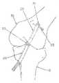
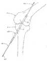
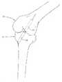
けが及び/又は事故の結果として頻繁に損傷を受ける一つの靱帯は、前十字靱帯(即ち
ACL)である。最初に図1及び図2を参照すると、ACL5が、頸骨10の頂部と大腿
骨15の底部との間に延在していることが理解される。損傷を受けたACLは、ひざ関節
の不安定性を引き起こし、大きな苦痛及び関節炎を引き起こし得る。One ligament that is frequently damaged as a result of injury and / or accident is the anterior cruciate ligament (or ACL). Referring initially to FIGS. 1 and 2, it can be seen that the ACL 5 extends between the top of the
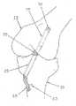
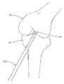
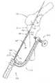
移植靱帯交換を通して損傷を受けたACLを回復させるため、多数の処置が開発された
。一般に、図3を参照すると、これらのACL交換処置は、頸骨10を通して骨トンネル
20を掘り、大腿骨15へと骨トンネル25を掘る、各工程を備える。幾つかの場合には
、大腿骨のトンネル25は、メクラ穴の形態で末端表面30で終わってもよい。他の場合
には、大腿骨トンネル25又は大腿骨トンネル25の延長部は、大腿骨15を通って完全
に通過し得る。一旦、頸骨トンネル20及び大腿骨トンネル25が形成されたならば、採
取された又は人工的な靱帯又は腱からなる移植靱帯35は、頸骨トンネル20を通って通
過させられ、膝関節の内部を横断し、大腿骨トンネル25へと至らせられる。次に、移植
靱帯35の末端部は、大腿骨トンネル25に固定され、移植靱帯35の供給端部は、頸骨
トンネル20に固定される。A number of procedures have been developed to recover damaged ACLs through graft ligament replacement. In general, referring to FIG. 3, these ACL exchange procedures comprise the steps of digging a
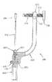
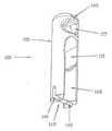
現在のところ、骨トンネル内に移植靱帯を固定するための多数の様々な方法が存在して
いる。一つの方法は、移植靱帯を骨トンネルの反対側壁に対して打ち込むように干渉ねじ
40(図4)を使用することである。別の方法は、ボタン45及び縫合糸50(図5)を
用いて又は交差ピン55(図6)を用いて骨トンネル内で移植靱帯を吊り下げることであ
る。更に別の方法は、移植靱帯を骨トンネルを通して完全に通過させ、ねじ60及びワッ
シャ65(図7)を用いて又はステープル(図示せず)を用いて移植靱帯を骨の外側に付
けることである。Currently, there are a number of different ways to secure a graft ligament within a bone tunnel. One method is to use an interference screw 40 (FIG. 4) to drive the graft ligament against the opposite side wall of the bone tunnel. Another method is to suspend the graft ligament within the bone tunnel using the
ACL回復の「黄金律」は、一般に、所謂「骨−腱−骨」固定であると考えられている
。この処置では、膝蓋腱の移植は、自然のACLを取り替えるため使用される。採取され
た腱の両端部に取り付けられているものは、骨移植物であり、患者の膝小僧(即ち膝蓋腱
)から取られたものと患者の頸骨(即ち、膝蓋腱が通常頸骨に取り付けられる位置におい
て)から取られたものとである。移植靱帯は、一つの骨移植物が干渉ねじを用いて大腿骨
トンネル内で固定され、他方の骨移植物が別の干渉ねじを用いて頸骨トンネル内に固定さ
れている状態で、骨トンネル内に配備される。多年に亘って、この処置は、首尾一貫した
強力で信頼性のある靱帯修繕処置を与えてきた。しかし、この処理は、非常に侵襲性が高
いとみなされ、多くの場合には、苦痛を伴い、典型的には、膝に目障りな傷を残し、膝小
僧に実質的な空洞部を残す。The “golden rule” of ACL recovery is generally considered to be so-called “bone-tendon-bone” fixation. In this procedure, patella tendon implantation is used to replace the natural ACL. Attached to both ends of the harvested tendon are bone grafts, taken from the patient's knee kid (ie, patella tendon) and the patient's tibia (ie, the position where the patella tendon is usually attached to the tibia) Taken from). A graft ligament is a bone tunnel with one bone graft fixed in the femoral tunnel using an interference screw and the other bone implant fixed in the tibial tunnel using another interference screw. Deployed. For many years, this procedure has provided a consistent, powerful and reliable ligament repair procedure. However, this process is considered very invasive and is often painful, typically leaving an annoying wound on the knee and leaving a substantial cavity in the knee kid.
その結果、最近では、例えば膝腱等の柔らかい組織移植の使用を組み込む代替処置が開
発された。しかし、膝腱等の軟組織移植は、骨トンネル内で安定化させることは困難であ
り得る。より詳しくは、膝腱を骨トンネルの反対側壁に対して侵略的に打ち込む干渉ねじ
の使用は、例えば移植滑り、腱の屈曲、組織壊死、及び、腱の切断等の問題を引き起こし
得る。更には、骨トンネル内に膝腱を吊り下げるため縫合糸のつり索(例えば、図5に示
されている)及び/又は交差ピン(例えば、図6に示されている)を使用することは、異
なる問題群を引き起こしかねず、例えば、縫合糸のつり索及び/又は交差ピンは、所謂「
風防ワイパー」効果で、移植靱帯が骨トンネル内を横方向に移動することを可能にする傾
向があり、これにより、移植靱帯とホスト骨との間の内部成長を妨げ、及び/又は、移植
組織への磨耗及び/又は他の損傷を引き起こす。更に加えて、膝腱を骨トンネル内で固定
するため交差ピンを使用すること(例えば、図6に示されている)は、なおも他の問題を
引き起こしかねない。例えば、膝腱を交差ピンに亘ってループにする際の困難性、交差ピ
ンが膝腱等の身体を通過する場合、通過したところで張力をかけている間に膝腱がその長
さに沿って引き裂かれるという問題等である。As a result, alternative procedures have recently been developed that incorporate the use of soft tissue grafts such as hamstrings. However, soft tissue transplants such as hamstrings can be difficult to stabilize within a bone tunnel. More specifically, the use of interference screws that invasively drive the hamstrings against the opposite side wall of the bone tunnel can cause problems such as graft slippage, tendon flexion, tissue necrosis, and tendon cuts. Furthermore, using a suspension cord (eg, shown in FIG. 5) and / or a cross pin (eg, shown in FIG. 6) to suspend the hamstrings in the bone tunnel is not possible. Can cause different groups of problems, e.g. suture tethers and / or crossing pins
The “windshield wiper” effect tends to allow the graft ligament to move laterally within the bone tunnel, thereby preventing ingrowth between the graft ligament and the host bone and / or graft tissue Cause wear and / or other damage to the In addition, the use of cross pins to secure the hamstrings in the bone tunnel (eg, as shown in FIG. 6) can still cause other problems. For example, difficulty in looping the hamstrings across the cross pin, if the cross pin passes through the body such as the hamstrings, the hamstrings along the length while applying tension when passing The problem is torn.
以上の結果として、本発明の一つの目的は、靱帯を再構成するための改善された装置を
提供することであり、該装置は、例えば、同種移植片、自家移植片、異種移植片、生体工
学的な組織移植片又は合成移植片等の様々な軟組織移植片から移植靱帯が作られることを
可能にするように構成され、該移植片は、横断固定ピンを使用して適所に固定されること
が意図されている。As a result of the foregoing, one object of the present invention is to provide an improved device for reconstructing a ligament, such as an allograft, autograft, xenograft, biological Constructed to allow graft ligaments to be made from various soft tissue grafts, such as engineered tissue grafts or synthetic grafts, which are secured in place using transverse fixation pins Is intended.
本発明の別の目的は、靱帯を再構成するための改善された方法を提供することであり、
該方法は、例えば、同種移植片、自家移植片、異種移植片、生体工学的な組織移植片又は
合成移植片等の様々な軟組織移植片から移植靱帯が作られることを可能にするように構成
され、該移植片は、横断固定ピンを使用して適所に固定されることが意図されている。Another object of the present invention is to provide an improved method for reconstructing a ligament,
The method is configured to allow a graft ligament to be made from a variety of soft tissue grafts, such as, for example, allografts, autografts, xenografts, bioengineered tissue grafts or synthetic grafts. And the implant is intended to be secured in place using transverse securing pins.
上記及び他の目的は、本発明によって取り組まれる。本発明は、本発明の一つの好まし
い形態において、移植靱帯支持ブロックの提供及び使用を含んでおり、該移植靱帯支持ブ
ロックは、ボディと、該ボディを通って延在する、移植孔及び横断固定ピン孔とを備え、
移植孔及び横断固定ピン孔の両方はボディの長さ方向軸に実質的に垂直に延在する。本発
明の一つの好ましい形態では、本発明は、移植靱帯支持ブロックを骨トンネル内へと挿入
するための設置器具を更に備え、移植靱帯支持ブロックを骨トンネル内に支持しつつ、ホ
スト骨の横断トンネルが移植靱帯支持ブロック内の横断固定ピン孔と整列した状態で、ホ
スト骨内に横断トンネルを形成する。These and other objects are addressed by the present invention. The present invention, in one preferred form of the invention, includes the provision and use of a graft ligament support block, the graft ligament support block comprising a body and a graft hole and transverse fixation extending through the body. With pin holes,
Both the graft hole and the transverse fixation pin hole extend substantially perpendicular to the longitudinal axis of the body. In one preferred form of the invention, the present invention further comprises a placement instrument for inserting the graft ligament support block into the bone tunnel, while traversing the host bone while supporting the graft ligament support block within the bone tunnel. A transverse tunnel is formed in the host bone with the tunnel aligned with the transverse fixation pin hole in the graft ligament support block.
使用法の一つの好ましい方法では、移植靱帯は、移植靱帯支持ブロック内の移植孔を通
してループ形成され、移植靱帯支持ブロックは設置器具に取り付けられる。移植靱帯の2
つの自由端部は、張力の作用下で設置基部の基端部へと固定されるのが好ましく、これに
より移植靱帯の2つの自由端部を縛り合わせる。移植靱帯の2つの自由端部を制御するこ
とに加えて、この構成は、移植靱帯支持ブロックを設置器具へと保持させる。次に、設置
器具は、ループ形成された移植靱帯の2つの自由端部が頸骨トンネルを通って戻り延ばし
た状態で、移植靱帯支持ブロックを頸骨トンネルを通して膝関節の内部を横切って大腿骨
トンネル内へと進めるため使用される。次に、横断トンネルは、該横断トンネルが移植靱
帯支持ブロック内の横断固定ピン孔と整列した状態で、ホスト骨内に形成される。移植靱
帯支持ブロックは、移植靱帯支持ブロックを大腿骨トンネル内にピン止めすることによっ
て、即ち、横断固定ピンをホスト骨内の横断トンネルに沿って移植靱帯支持ブロックの横
断固定ピン孔内へと進めることによって、適所に固定される。ループ形成された移植靱帯
の2つの自由端部は、設置器具から解放され、設置器具は、移植靱帯支持ブロックから取
り外され、設置器具が手術箇所から引き抜かれる。最終的に、ループ形成された移植靱帯
の2つの自由端部が頸骨に固定され、よって、ACLの修繕を完了する。所望の場合には
、頸骨の取り付けは、第2の移植靱帯支持ブロックを使用して実現することができる。In one preferred method of use, the graft ligament is looped through a graft hole in the graft ligament support block, and the graft ligament support block is attached to an installation instrument. 2 of transplant ligament
The two free ends are preferably secured to the proximal end of the installed base under the action of tension, thereby tying the two free ends of the graft ligament. In addition to controlling the two free ends of the graft ligament, this configuration holds the graft ligament support block to the placement instrument. The placement instrument then passes the graft ligament support block through the tibial tunnel and across the interior of the knee joint with the two free ends of the looped graft ligament extending back through the tibial tunnel and into the femoral tunnel. Used to advance to. The transverse tunnel is then formed in the host bone with the transverse tunnel aligned with the transverse fixation pin hole in the graft ligament support block. The graft ligament support block is advanced by pinning the graft ligament support block into the femoral tunnel, i.e., the transverse fixation pin along the transverse tunnel in the host bone and into the transverse fixation pin hole of the graft ligament support block To fix it in place. The two free ends of the looped graft ligament are released from the placement instrument, the placement instrument is removed from the graft ligament support block, and the placement instrument is withdrawn from the surgical site. Eventually, the two free ends of the looped graft ligament are secured to the tibia, thus completing the ACL repair. If desired, tibial attachment can be achieved using a second graft ligament support block.
本発明の更なる特徴によれば、靱帯を再構成する際に使用するための装置が提供される
。該装置は、骨トンネル内で移植靱帯を支持するための移植靱帯支持ブロックを備え、該
移植靱帯支持ブロックは、末端部、基端部、及び、前記末端部及び前記基端部の間に延在
する長さ方向軸を有するボディであって、該基端部は、骨トンネルを通した前記靱帯支持
ブロックの引き抜きを容易にするようにテーパーが形成されている前記ボディと、前記長
さ方向軸と交差して前記ボディを通って延在し、且つ、移植靱帯を収容するように構成さ
れた移植孔と、前記長さ方向軸と交差して前記ボディを通って延在し、且つ、横断固定ピ
ンを収容するように構成された横断固定ピン孔と、を備える。According to a further feature of the present invention, an apparatus is provided for use in reconstructing a ligament. The apparatus includes a graft ligament support block for supporting a graft ligament within a bone tunnel, the graft ligament support block extending between a distal end, a proximal end, and the distal end and the proximal end. A body having an existing longitudinal axis, the proximal end of which is tapered to facilitate withdrawal of the ligament support block through a bone tunnel; and the longitudinal direction Extending through the body intersecting the axis and configured to receive a graft ligament; extending through the body intersecting the longitudinal axis; and A transverse fixation pin hole configured to receive a transverse fixation pin.
本発明の更なる特徴によれば、骨トンネル内で移植靱帯を固定するための方法が提供さ
れ、本方法は、
(1) 移植靱帯を、移植靱帯支持ブロック内の移植孔を通してループ形成し、前記移植
靱帯支持ブロックを前記骨トンネル内に進め、該移植靱帯支持ブロックを前記骨トンネル
に沿って引き抜き、移植靱帯が移植靱帯支持ブロックの移植孔を通してループ形成された
状態で該移植靱帯支持ブロックを進め、ホスト骨内に横断トンネルを形成して前記移植靱
帯支持ブロックが前記ホスト骨内で前記横断トンネルと整列させ、
(2) 横断固定ピンを前記ホスト骨の前記横断トンネルに沿って前記移植靱帯支持ブロ
ックの前記横断固定ピン孔へと進めることによって前記骨トンネル内で前記移植靱帯支持
ブロックをピン止めする、各工程を備える。According to a further feature of the present invention, there is provided a method for securing a graft ligament within a bone tunnel, the method comprising:
(1) Looping the graft ligament through a graft hole in the graft ligament support block, advancing the graft ligament support block into the bone tunnel, withdrawing the graft ligament support block along the bone tunnel, Advancing the graft ligament support block in a looped manner through a graft hole in the graft ligament support block, forming a transverse tunnel in the host bone to align the graft ligament support block with the transverse tunnel in the host bone;
(2) Pinning the graft ligament support block within the bone tunnel by advancing a transverse fixation pin along the transverse tunnel of the host bone to the transverse fixation pin hole of the graft ligament support block Is provided.
本発明の更なる特徴によれば、骨トンネル内で移植靱帯を修正するための方法が提供さ
れ、本方法は、
横断固定ピンを移植靱帯支持ブロック内の横断固定ピン孔及びホスト骨の横断トンネル
から引き抜くことによって、前記移植靱帯支持ブロックを前記骨トンネル内で取り外し、
前記移植靱帯支持ブロックを前記骨トンネルに沿って引き抜き、
前記支持ブロック内の横断固定ピン孔が前記横断トンネルと整列されるように、移植靱
帯支持ブロックを前記骨トンネル内に進め、
前記横断固定ピンを前記ホスト骨内の前記横断トンネルに沿って前記移植靱帯支持ブロ
ック内の前記横断固定ピン内へと進めることによって前記移植靱帯支持ブロックを前記骨
トンネル内でピン止めする、各工程を備える。According to a further feature of the present invention, there is provided a method for modifying a graft ligament within a bone tunnel, the method comprising:
Removing the graft ligament support block within the bone tunnel by withdrawing the transverse fixation pin from the transverse fixation pin hole in the graft ligament support block and the host bone transverse tunnel;
Withdrawing the graft ligament support block along the bone tunnel;
Advance the graft ligament support block into the bone tunnel such that transverse fixation pin holes in the support block are aligned with the transverse tunnel;
Pinning the graft ligament support block in the bone tunnel by advancing the transverse fixation pin along the transverse tunnel in the host bone and into the transverse fixation pin in the graft ligament support block Is provided.
本発明の更なる特徴によれば、靱帯を再構成する際に使用するための装置が提供され、
本装置は骨トンネル内で移植靱帯を支持するための移植靱帯支持ブロックを備え、前記移
植靱帯支持ブロックは、末端部と、基端部と、前記末端部及び前記基端部の間で延在する
長さ方向軸とを有するボディと、
前記長さ方向軸と交差し且つ移植靱帯を収容するように構成された、前記ボディを通って
延在する移植孔であって、該移植孔は、前記長さ方向軸に沿って与えられた長さを持ち、
該与えられた長さは前記移植靱帯の与えられた断面寸法に実質的に等しい、前記移植孔と
、
前記長さ方向軸と交差し且つ横断固定ピンを収容するように構成された、前記ボディを
通って延在する横断固定ピン孔と、
を備える。According to a further feature of the present invention, there is provided an apparatus for use in reconstructing a ligament,
The apparatus includes a graft ligament support block for supporting a graft ligament within a bone tunnel, the graft ligament support block extending between a distal end, a proximal end, and the distal end and the proximal end A body having a longitudinal axis to
A graft hole extending through the body configured to intersect the longitudinal axis and accommodate a graft ligament, the graft hole being provided along the longitudinal axis Have a length,
The graft hole, wherein the given length is substantially equal to a given cross-sectional dimension of the graft ligament;
A transverse fixation pin hole extending through the body and configured to intersect the longitudinal axis and receive a transverse fixation pin;
Is provided.
本発明の更なる特徴によれば、骨トンネル内で移植靱帯を固定するための方法が提供さ
れ、本方法は、
移植靱帯の与えられた断面寸法に実質的に等しくなるようにサイズが定められた移植孔
を備えた移植靱帯支持ブロックを選択し、
前記移植靱帯を、移植靱帯支持ブロック内の前記移植孔を通してループ形成し、
前記移植靱帯支持ブロックを前記骨トンネル内に進め、
横断トンネルが前記移植靱帯支持ブロック内の横断固定ピン孔と整列した状態で、ホス
ト骨に横断トンネルを形成し、
横断固定ピンを前記ホスト骨の前記横断トンネルに沿って前記移植靱帯支持ブロックの
前記横断固定ピン孔へと進めることによって前記骨トンネル内で前記移植靱帯支持ブロッ
クをピン止めする、各工程を備える。According to a further feature of the present invention, there is provided a method for securing a graft ligament within a bone tunnel, the method comprising:
Selecting a graft ligament support block with a graft hole sized to be substantially equal to a given cross-sectional dimension of the graft ligament,
Looping the graft ligament through the graft hole in a graft ligament support block;
Advance the graft ligament support block into the bone tunnel;
Forming a transverse tunnel in the host bone with the transverse tunnel aligned with the transverse fixation pin hole in the graft ligament support block;
Pinning the graft ligament support block within the bone tunnel by advancing a transverse fixation pin along the transverse tunnel of the host bone to the transverse fixation pin hole of the graft ligament support block.
本発明の別の特徴によれば、骨トンネル内で移植靱帯を固定するための方法が提供され
、本方法は、
ホスト骨内に横断トンネルを形成し、
移植靱帯の与えられた断面寸法に実質的に等しくなるようにサイズが定められた移植孔
を備えた移植靱帯支持ブロックを選択し、
前記移植靱帯を、移植靱帯支持ブロック内の前記移植孔を通してループ形成し、
前記移植靱帯支持ブロック内の横断固定ピン孔が前記横断トンネルと整列するように、
前記移植靱帯支持ブロックを前記骨トンネル内に進め、
横断固定ピンを前記ホスト骨の前記横断トンネルに沿って前記移植靱帯支持ブロックの
前記横断固定ピン孔へと進めることによって前記骨トンネル内で前記移植靱帯支持ブロッ
クをピン止めする、各工程を備える。According to another feature of the invention, a method is provided for securing a graft ligament within a bone tunnel, the method comprising:
Forming a transverse tunnel in the host bone,
Selecting a graft ligament support block with a graft hole sized to be substantially equal to a given cross-sectional dimension of the graft ligament,
Looping the graft ligament through the graft hole in a graft ligament support block;
Such that transverse fixation pin holes in the graft ligament support block are aligned with the transverse tunnel,
Advance the graft ligament support block into the bone tunnel;
Pinning the graft ligament support block within the bone tunnel by advancing a transverse fixation pin along the transverse tunnel of the host bone to the transverse fixation pin hole of the graft ligament support block.
本発明の更なる特徴によれば、靱帯を再構成する際に使用するための装置が提供される
。本装置は、骨トンネル内で移植靱帯を支持するための移植靱帯支持ブロックを備え、前
記移植靱帯支持ブロックは、
末端部と、基端部と、前記末端部及び前記基端部の間で延在する長さ方向軸とを有する
ボディと、
前記長さ方向軸と交差し且つ移植靱帯を収容するように構成された、前記ボディを通っ
て延在する移植孔と、
前記長さ方向軸と交差し且つ横断固定ピンを収容するように構成された、前記ボディを通
って延在する横断固定ピン孔と、
基端部及び末端部を有する横断固定ピンであって、該基端部は、該横断固定ピンの前記骨
トンネルからの取り外しを援助するように内部タップ孔を形成する、前記横断固定ピンと
、
を備える。According to a further feature of the present invention, an apparatus is provided for use in reconstructing a ligament. The device comprises a graft ligament support block for supporting the graft ligament within a bone tunnel, the graft ligament support block comprising:
A body having a distal end, a proximal end, and a longitudinal axis extending between the distal end and the proximal end;
A graft hole extending through the body configured to intersect the longitudinal axis and receive a graft ligament;
A transverse fixation pin hole extending through the body and configured to intersect the longitudinal axis and receive a transverse fixation pin;
A transverse fixation pin having a proximal end and a distal end, wherein the proximal end forms an internal tapped hole to assist in removal of the transverse fixation pin from the bone tunnel; and
Is provided.
本発明の更なる特徴によれば、骨トンネル内で移植靱帯を修正するための方法が提供さ
れ、本方法は、
取り外し器具を横断固定ピン内の内部タップ孔と係合させ、
前記取り外し器具が横断固定ピン内の内部タップ孔と係合した状態で、前記骨トンネル
から前記横断固定ピンを引き抜き、移植靱帯支持ブロックを前記骨トンネルに沿って引き
戻し、
移植靱帯支持ブロックを前記骨トンネル内へと配置し、
前記横断固定ピンを前記ホスト骨内の前記横断トンネルに沿って前記移植靱帯支持ブロ
ック内の前記横断固定ピン内へと進めることによって前記移植靱帯支持ブロックを前記骨
トンネル内でピン止めする、各工程を備える。According to a further feature of the present invention, there is provided a method for modifying a graft ligament within a bone tunnel, the method comprising:
Engage the removal implement with the internal tap hole in the transverse fixation pin;
With the removal instrument engaged with an internal tap hole in the transverse fixation pin, withdrawing the transverse fixation pin from the bone tunnel and pulling back the graft ligament support block along the bone tunnel;
Placing a graft ligament support block into the bone tunnel;
Pinning the graft ligament support block in the bone tunnel by advancing the transverse fixation pin along the transverse tunnel in the host bone and into the transverse fixation pin in the graft ligament support block Is provided.
本発明の更なる特徴によれば、靱帯を再構成する際に使用するためのシステムが提供さ
れ、該システムは、骨トンネル内で移植靱帯を支持するための移植靱帯支持ブロックを備
え、前記移植靱帯支持ブロックは、
末端部と、基端部と、前記末端部及び前記基端部の間で延在する長さ方向軸とを有する
ボディと、
前記長さ方向軸と交差し且つ移植靱帯を収容するように構成された、前記ボディを通っ
て延在する移植孔と、
末端部と、基端部と、前記末端部及び前記基端部の間で延在する長さ方向軸と、前記末
端部に設けられた第1の部分と、前記基端部に設けられた第2の部分であって、前記第1
の部分は該第2の部分よりも小さい前記第2の部分と、前記第1の部分及び前記第2の部
分の間に構成された環状肩部と、を有する段付き固定ピンであって、前記第1の部分、前
記第2の部分及び前記環状肩部は、前記長さ方向軸に垂直な与えられた平面の断面におい
て与えられたプロフィールを形成する、前記段付き固定ピンと、
末端部と、基端部と、前記末端部及び前記基端部の間で延在する長さ方向軸と、を有す
る段付き横断トンネルドリルであって、該段付き横断トンネルドリルは、前記横断固定ピ
ン孔の経路と整列するように構成された前記骨トンネルの一部分を通して段付き横断トン
ネルを提供するように前記段付き固定ピンの前記与えられたプロフィールに対応し、前記
横断固定ピン孔は、前記長さ方向軸と交差して前記ボディを通って延在すると共に横断固
定ピンを収容するように構成されている、前記横断トンネルドリルと、
を備える。According to a further feature of the present invention, there is provided a system for use in reconstructing a ligament, the system comprising a graft ligament support block for supporting a graft ligament within a bone tunnel, wherein the graft The ligament support block
A body having a distal end, a proximal end, and a longitudinal axis extending between the distal end and the proximal end;
A graft hole extending through the body configured to intersect the longitudinal axis and receive a graft ligament;
A distal end, a proximal end, a longitudinal axis extending between the distal end and the proximal end, a first portion provided at the distal end, and provided at the proximal end A second part, said first
A stepped fixing pin having the second part smaller than the second part and an annular shoulder formed between the first part and the second part, The stepped locking pin, wherein the first portion, the second portion and the annular shoulder form a given profile in a cross section of a given plane perpendicular to the longitudinal axis;
A stepped transverse tunnel drill having a distal end, a proximal end, and a longitudinal axis extending between the distal end and the proximal end, the stepped transverse tunnel drill comprising the transverse transverse drill Corresponding to the given profile of the stepped fixation pin to provide a stepped transverse tunnel through a portion of the bone tunnel configured to align with a path of the fixation pin hole, the transverse fixation pin hole being The transverse tunnel drill extending through the body intersecting the longitudinal axis and configured to receive a transverse fixation pin; and
Is provided.
本発明の更なる特徴によれば、骨トンネル内で移植靱帯を固定するための方法が提供さ
れ、本方法は、
移植靱帯を、移植靱帯支持ブロック内の移植孔を通してループ形成し、
前記移植靱帯支持ブロックを前記骨トンネル内に進め、
段付き横断トンネルドリルを用いて前記ホスト骨内に段付き横断トンネルを形成し、該
段付き横断トンネルは前記移植靱帯支持ブロック内の横断固定ピン孔と整列しており、
段付き横断固定ピンを前記ホスト骨の前記横断トンネルに沿って前記移植靱帯支持ブロ
ックの前記横断固定ピン孔へと進めることによって前記骨トンネル内で前記移植靱帯支持
ブロックをピン止めする、各工程を備える。According to a further feature of the present invention, there is provided a method for securing a graft ligament within a bone tunnel, the method comprising:
Looping the graft ligament through a graft hole in the graft ligament support block;
Advance the graft ligament support block into the bone tunnel;
Using a stepped transverse tunnel drill to form a stepped transverse tunnel in the host bone, the stepped transverse tunnel being aligned with a transverse fixation pin hole in the graft ligament support block;
Pinning the graft ligament support block within the bone tunnel by advancing a stepped transverse fixation pin along the transverse tunnel of the host bone to the transverse fixation pin hole of the graft ligament support block; Prepare.
本発明の更なる特徴によれば、骨トンネル内で移植靱帯を固定するための方法が提供さ
れ、本方法は、
段付き横断トンネルドリルを用いてホスト骨内に段付き横断トンネルを形成し、
移植靱帯を、移植靱帯支持ブロック内の移植孔を通してループ形成し、
前記移植靱帯支持ブロック内の横断固定ピン孔が前記段付き横断トンネルと整列するよ
うに前記移植靱帯支持ブロックを前記骨トンネル内に進め、
段付き横断固定ピンを前記ホスト骨の前記段付き横断トンネルに沿って前記移植靱帯支
持ブロックの前記横断固定ピン孔へと進めることによって前記骨トンネル内で前記移植靱
帯支持ブロックをピン止めする、各工程を備える。According to a further feature of the present invention, there is provided a method for securing a graft ligament within a bone tunnel, the method comprising:
Using a stepped crossing tunnel drill to form a stepped crossing tunnel in the host bone,
Looping the graft ligament through a graft hole in the graft ligament support block;
Advancing the graft ligament support block into the bone tunnel such that transverse fixation pin holes in the graft ligament support block are aligned with the stepped transverse tunnel;
Pinning the graft ligament support block within the bone tunnel by advancing a stepped transverse fixation pin along the stepped transverse tunnel of the host bone to the transverse fixation pin hole of the graft ligament support block; A process is provided.
本発明の更なる特徴によれば、靱帯を再構成する際に使用するためのシステムが提供さ
れ、本システムは、
骨トンネル内で移植靱帯を支持するための移植靱帯支持ブロックを備え、
前記移植靱帯支持ブロックは、
末端部と、基端部と、前記末端部及び前記基端部の間で延在する長さ方向軸と、設置器
具による係合のための少なくとも1つの要素とを有するボディと、
前記長さ方向軸と交差し且つ移植靱帯を収容するように構成された、前記ボディを通っ
て延在する移植孔と、
前記長さ方向軸と交差し且つ横断固定ピンを収容するように構成された、前記ボディを
通って延在する横断固定ピン孔と、
設置器具であって、該設置器具は、
ホルダーであって、該ホルダーは、
末端部、基端部、及び、該末端部及び該基端部の間に延在する長さ方向軸を有する
シャフトであって、該シャフトの前記基端部は前記ボディの前記少なくとも1つの要素と
係合するように構成された、前記シャフトと、
前記シャフトの前記基端部に取り付けられたハンドルと、
を備える前記ホルダーと、
前記ホルダーに解放可能に固定されるように構成されたドリルガイドであって、該
ドリルガイドは、
末端部及び基端部を備える張り出し部材であって、該張り出し部材の前記基端部は
、前記ホルダーに解放可能に固定されるように構成された、前記張り出し部材と、
前記張り出し部材の前記末端部に移動可能に取り付けられたドリルスリーブであっ
て、該ドリルスリーブは、該スリーブを通って延在するドリル管腔部を備え、該ドリルス
リーブは、深さマーカーを有し、前記張り出し部材の前記末端部及び前記ドリル部リーブ
の前記深さマーカーは、適切な横断トンネル深さを表示するように構成されている、前記
ドリルスリーブと、を備える、前記ドリルスリーブと、
を有する、前記ドリルガイドと、
を備える、前記設置器具と、
末端部及び基端部を有する横断トンネルドリルであって、該横断トンネルドリルの前記
末端部は、前記骨トンネルを通って横断骨トンネルを掘削するように前記ドリルスリーブ
を通って配置するように構成され、前記横断トンネルドリルは、前記基端部及び前記末端
部の間に配置されたマーカーを有し、前記横断トンネルドリル及び前記ドリルスリーブ上
の前記深さマーカーは、前記横断トンネルドリルの前記末端部の与えられた深さを表示す
るように構成されている、前記横断トンネルドリルと、
を備える。According to a further feature of the present invention, there is provided a system for use in reconstructing a ligament, the system comprising:
A graft ligament support block for supporting the graft ligament within the bone tunnel,
The graft ligament support block is
A body having a distal end, a proximal end, a longitudinal axis extending between the distal end and the proximal end, and at least one element for engagement by an installation tool;
A graft hole extending through the body configured to intersect the longitudinal axis and receive a graft ligament;
A transverse fixation pin hole extending through the body and configured to intersect the longitudinal axis and receive a transverse fixation pin;
An installation tool, the installation tool comprising:
A holder, the holder being
A shaft having a distal end, a proximal end, and a longitudinal axis extending between the distal end and the proximal end, wherein the proximal end of the shaft is the at least one element of the body Said shaft configured to engage with;
A handle attached to the proximal end of the shaft;
The holder comprising:
A drill guide configured to be releasably secured to the holder, the drill guide comprising:
An overhang member comprising a distal end and a base end, wherein the base end of the overhang member is configured to be releasably secured to the holder; and
A drill sleeve movably attached to the distal end of the overhang member, the drill sleeve comprising a drill lumen extending through the sleeve, the drill sleeve having a depth marker. The drill sleeve comprising: the distal end of the overhang member and the depth marker of the drill portion leave configured to indicate an appropriate transverse tunnel depth;
Having the drill guide;
The installation tool comprising:
A transverse tunnel drill having a distal end and a proximal end, wherein the distal end of the transverse tunnel drill is configured to be positioned through the drill sleeve to drill a transverse bone tunnel through the bone tunnel. The transverse tunnel drill has a marker disposed between the proximal end and the distal end, and the depth marker on the transverse tunnel drill and the drill sleeve is the distal end of the transverse tunnel drill. Said transverse tunnel drill configured to display a given depth of the part;
Is provided.
本発明の更なる特徴によれば、骨トンネル内で移植靱帯を固定するための方法が提供さ
れ、本方法は、
移植靱帯を、移植靱帯支持ブロック内の移植孔を通してループ形成し、
前記移植靱帯支持ブロックを前記骨トンネル内に進め、
ドリルガイドを前記移植支持ブロックに取り付けた状態で位置決めし、該ドリルガイド
は、張り出し部材と、該張り出し部材に移動可能に取り付けられ且つ深さマーカーを有す
るドリルスリーブと、を備えており、
前記張り出し部材内の前記ドリルスリーブを前記骨トンネルに向かって移動させ、前記
ドリルスリーブ上の前記深さマーカーを読み取ることにより、前記ドリルスリーブ及び前
記張り出し部材を用いて適切な横断トンネル深さを決定し、
横断トンネルドリルを配置されたマーカーに従った与えられた深さへと掘削することに
より、適切な横断トンネル深さへと前記ホスト骨内で横断トンネルを形成し、該横断トン
ネルは前記移植靱帯支持ブロック内の横断固定ピン孔と整列しており、
横断固定ピンを前記ホスト骨の前記横断トンネルに沿って前記移植靱帯支持ブロックの
前記横断固定ピン孔へと進めることによって前記骨トンネル内で前記移植靱帯支持ブロッ
クをピン止めする、各工程を備える。According to a further feature of the present invention, there is provided a method for securing a graft ligament within a bone tunnel, the method comprising:
Looping the graft ligament through a graft hole in the graft ligament support block;
Advance the graft ligament support block into the bone tunnel;
Positioning a drill guide attached to the graft support block, the drill guide comprising an overhanging member and a drill sleeve movably attached to the overhanging member and having a depth marker;
Determine the appropriate transverse tunnel depth using the drill sleeve and the overhang member by moving the drill sleeve in the overhang member toward the bone tunnel and reading the depth marker on the drill sleeve. And
Drilling a transverse tunnel drill to a given depth according to the placed marker to form a transverse tunnel in the host bone to the appropriate transverse tunnel depth, the transverse tunnel supporting the graft ligament Aligned with the transverse fixing pin hole in the block,
Pinning the graft ligament support block within the bone tunnel by advancing a transverse fixation pin along the transverse tunnel of the host bone to the transverse fixation pin hole of the graft ligament support block.
本発明の更なる特徴によれば、骨トンネル内で移植靱帯を固定するための方法が提供さ
れ、本方法は、
ドリルガイドを前記骨トンネル内に挿入されたリーマーに取り付けた状態で位置決めし、
該ドリルガイドは、張り出し部材と、該張り出し部材に移動可能に取り付けられ且つ深さ
マーカーを有するドリルスリーブと、を備えており、
前記張り出し部材内の前記ドリルスリーブを前記骨トンネルに向かって移動させ、前記
ドリルスリーブ上の前記深さマーカーを読み取ることにより、前記ドリルスリーブ及び前
記張り出し部材を用いて適切な横断トンネル深さを決定し、
横断トンネルドリルを配置されたマーカーに従った与えられた深さへと掘削することに
より、適切な横断トンネル深さへと前記ホスト骨内で横断トンネルを形成し、
前記リーマーを前記骨トンネルから取り外し、
移植靱帯支持ブロック内の移植孔を通して移植靱帯をループ形成し、
前記移植靱帯支持ブロック内の横断固定ピン孔が前記横断トンネルと整列するように前
記移植靱帯支持ブロックを前記骨トンネル内へと進め、
横断固定ピンを前記ホスト骨の前記横断トンネルに沿って前記移植靱帯支持ブロックの
前記横断固定ピン孔へと進めることによって前記骨トンネル内で前記移植靱帯支持ブロッ
クをピン止めする、各工程を備える。According to a further feature of the present invention, there is provided a method for securing a graft ligament within a bone tunnel, the method comprising:
Position the drill guide attached to the reamer inserted into the bone tunnel,
The drill guide includes an overhang member, and a drill sleeve movably attached to the overhang member and having a depth marker.
Determine the appropriate transverse tunnel depth using the drill sleeve and the overhang member by moving the drill sleeve in the overhang member toward the bone tunnel and reading the depth marker on the drill sleeve. And
Forming a transverse tunnel in the host bone to the appropriate transverse tunnel depth by drilling the transverse tunnel drill to a given depth according to the placed marker;
Removing the reamer from the bone tunnel;
Looping the graft ligament through the graft hole in the graft ligament support block;
Advancing the graft ligament support block into the bone tunnel such that transverse fixation pin holes in the graft ligament support block are aligned with the transverse tunnel;
Pinning the graft ligament support block within the bone tunnel by advancing a transverse fixation pin along the transverse tunnel of the host bone to the transverse fixation pin hole of the graft ligament support block.
本発明の更なる特徴によれば、靱帯を再構成する際に使用するためのシステムが提供さ
れ、本システムは、
骨トンネル内で移植靱帯を支持するための移植靱帯支持ブロックを備え、
前記移植靱帯支持ブロックは、
末端部と、基端部と、前記末端部及び前記基端部の間で延在する長さ方向軸と、設置器
具による係合のための少なくとも1つの要素とを有するボディと、
前記長さ方向軸と交差し且つ移植靱帯を収容するように構成された、前記ボディを通っ
て延在する移植孔と、
前記長さ方向軸と交差し且つ横断固定ピンを収容するように構成された、前記ボディを
通って延在する横断固定ピン孔と、
設置器具であって、該設置器具は、
ホルダーであって、該ホルダーは、
末端部、基端部、及び、該末端部及び該基端部の間に延在する長さ方向軸を有する
シャフトであって、該シャフトの前記基端部は前記ボディの前記少なくとも1つの要素と
係合するように構成された、前記シャフトと、
前記シャフトの前記基端部に取り付けられたハンドルと、
を備える前記ホルダーと、
前記ホルダーに解放可能に固定されるように構成されたドリルガイドであって、該
ドリルガイドは、
末端部及び基端部を備える張り出し部材であって、該張り出し部材の前記基端部は
、前記ホルダーに解放可能に固定されるように構成された、前記張り出し部材と、
前記張り出し部材の前記末端部に移動可能に取り付けられたドリルスリーブであっ
て、該ドリルスリーブは、該スリーブを通って延在するドリル管腔部を備える、前記ドリ
ルスリーブと、
を備える、前記ドリルガイドと、
を有する、前記設置器具と、
末端部及び基端部を有する横断トンネルドリルであって、該横断トンネルドリルの前記
末端部は、前記骨トンネルを通って横断骨トンネルを掘削するように前記ドリルスリーブ
を通って配置するように構成され、前記横断トンネルドリルは、掘削を所定の深さに制限
するように前記ドリルスリーブと係合するように構成された停止要素を有する、前記横断
トンネルドリルと、
を備える。According to a further feature of the present invention, there is provided a system for use in reconstructing a ligament, the system comprising:
A graft ligament support block for supporting the graft ligament within the bone tunnel,
The graft ligament support block is
A body having a distal end, a proximal end, a longitudinal axis extending between the distal end and the proximal end, and at least one element for engagement by an installation tool;
A graft hole extending through the body configured to intersect the longitudinal axis and receive a graft ligament;
A transverse fixation pin hole extending through the body and configured to intersect the longitudinal axis and receive a transverse fixation pin;
An installation tool, the installation tool comprising:
A holder, the holder being
A shaft having a distal end, a proximal end, and a longitudinal axis extending between the distal end and the proximal end, wherein the proximal end of the shaft is the at least one element of the body Said shaft configured to engage with;
A handle attached to the proximal end of the shaft;
The holder comprising:
A drill guide configured to be releasably secured to the holder, the drill guide comprising:
An overhang member comprising a distal end and a base end, wherein the base end of the overhang member is configured to be releasably secured to the holder; and
A drill sleeve movably attached to the distal end of the overhang member, the drill sleeve comprising a drill lumen extending through the sleeve; and
The drill guide comprising:
Having the installation tool;
A transverse tunnel drill having a distal end and a proximal end, wherein the distal end of the transverse tunnel drill is configured to be positioned through the drill sleeve to drill a transverse bone tunnel through the bone tunnel. The transverse tunnel drill having a stop element configured to engage the drill sleeve to limit excavation to a predetermined depth;
Is provided.
本発明の更なる特徴によれば、靱帯を再構成する際に使用するためのシステムが提供さ
れ、本システムは、
骨トンネル内で移植靱帯を支持するための移植靱帯支持ブロックを備え、
前記移植靱帯支持ブロックは、
末端部と、基端部と、前記末端部及び前記基端部の間で延在する長さ方向軸とを有する
ボディと、
前記長さ方向軸と交差し且つ移植靱帯を収容するように構成された、前記ボディを通っ
て延在する移植孔と、
末端部と、基端部と、前記末端部及び前記基端部の間で延在する長さ方向軸と、前記末
端部に設けられた第1の部分と、前記基端部に設けられた第2の部分であって、前記第1
の部分は該第2の部分よりも小さい前記第2の部分と、前記第1の部分及び前記第2の部
分の間に構成された環状肩部と、を有する段付き横断固定ピンであって、前記第1の部分
、前記第2の部分及び前記環状肩部は、前記長さ方向軸に垂直な与えられた平面の断面に
おいて与えられたプロフィールを形成する、前記段付き横断固定ピンと、
末端部と、基端部と、前記末端部及び前記基端部の間で延在する長さ方向軸と、を有す
る段付き横断トンネルドリルであって、該段付き横断トンネルドリルは、前記段付き横断
固定ピンの前記与えられたプロフィールを受け入れるように構成された前記骨トンネルを
通して段付き横断トンネルを提供するように前記団付き横断ドリルは該段付き横断固定ピ
ンの前記与えられたプロフィールに対応する、前記段付き横断トンネルドリルと、
末端部及び基端部を有する深さゲージであって、該深さゲージの前記末端部は、前記段
付き固定ピンの前記環状肩部に対応する前記段付き横断トンネルの一部分と係合するため
ドリルスリーブを通して配置するように構成され、前記深さゲージは、前記段付き固定ピ
ンの前記環状肩部に対応する前記一部分と骨表面との間の前記横断固定ピン孔の深さを表
示するように、前記末端部及び前記基端部の間に標識を有する、前記深さゲージと、
を備える。According to a further feature of the present invention, there is provided a system for use in reconstructing a ligament, the system comprising:
A graft ligament support block for supporting the graft ligament within the bone tunnel,
The graft ligament support block is
A body having a distal end, a proximal end, and a longitudinal axis extending between the distal end and the proximal end;
A graft hole extending through the body configured to intersect the longitudinal axis and receive a graft ligament;
A distal end, a proximal end, a longitudinal axis extending between the distal end and the proximal end, a first portion provided at the distal end, and provided at the proximal end A second part, said first
A stepped transverse securing pin having the second part smaller than the second part and an annular shoulder formed between the first part and the second part, The stepped transverse fixation pin, wherein the first portion, the second portion and the annular shoulder form a given profile in a given plane cross section perpendicular to the longitudinal axis;
A stepped transverse tunnel drill having a distal end, a proximal end, and a longitudinal axis extending between the distal end and the proximal end, wherein the stepped transverse tunnel drill includes the stepped transverse tunnel drill. The bridging transverse drill corresponds to the given profile of the stepped transverse fixation pin to provide a stepped transverse tunnel through the bone tunnel configured to accept the given profile of the stepped transverse fixation pin The stepped cross tunnel drill,
A depth gauge having a distal end and a proximal end, wherein the distal end of the depth gauge engages a portion of the stepped transverse tunnel corresponding to the annular shoulder of the stepped securing pin. Configured to be positioned through a drill sleeve, the depth gauge indicating the depth of the transverse fixation pin hole between the portion corresponding to the annular shoulder of the stepped fixation pin and the bone surface The depth gauge having a mark between the distal end and the proximal end; and
Is provided.
本発明の更なる特徴によれば、骨トンネル内で移植靱帯を固定するための方法が提供さ
れ、本方法は、
移植靱帯を、移植靱帯支持ブロック内の移植孔を通してループ形成し、
前記移植靱帯支持ブロックを前記骨トンネル内に進め、
張り出し部材に対するドリルスリーブの第1の組の深さマーカーの位置を読み取ること
によって適切な横断トンネル深さを決定し、
横断トンネルが移植靱帯支持ブロック内の横断固定ピン孔と整列した状態で、前記適切
な横断トンネル深さへと前記横断トンネルを掘削するように第2の組の深さマーカーを有
する横断トンネルドリルを使用して前記ホスト骨内に横断トンネルを形成し、
ドリルスリーブ上の第1の組の深さマーカーにより決定された適切な横断トンネル深さ
に基づいて横断固定ピンを選択することによって、骨トンネル内で移植靱帯支持ブロック
をピン止めし、選択された横断固定ピンをホスト骨内の横断トンネルに沿って移植靱帯支
持ブロック内の横断固定ピン孔へと進める、各工程を備える。According to a further feature of the present invention, there is provided a method for securing a graft ligament within a bone tunnel, the method comprising:
Looping the graft ligament through a graft hole in the graft ligament support block;
Advance the graft ligament support block into the bone tunnel;
Determine the appropriate transverse tunnel depth by reading the position of the first set of depth markers of the drill sleeve relative to the overhang member;
With the transverse tunnel aligned with the transverse fixation pin hole in the graft ligament support block, a transverse tunnel drill having a second set of depth markers to drill the transverse tunnel to the appropriate transverse tunnel depth Use to form a transverse tunnel in the host bone,
Pin the graft ligament support block within the bone tunnel by selecting the transverse fixation pin based on the appropriate transverse tunnel depth determined by the first set of depth markers on the drill sleeve and selected Each step includes advancing a transverse fixation pin along a transverse tunnel in the host bone to a transverse fixation pin hole in the graft ligament support block.
本発明の更なる特徴によれば、骨トンネル内で移植靱帯を固定するための方法が提供さ
れ、本方法は、
張り出し部材に対するドリルスリーブ上の第1の組の深さマーカーの位置を読み取るこ
とによって適切な横断トンネル深さを決定し、
前記横断トンネルを前記適切な横断トンネル深さへと掘削するように第2の組の深さマ
ーカーを有する横断トンネルドリルを使用してホスト骨内に横断トンネルを形成し、
移植靱帯を、移植靱帯支持ブロック内の移植孔を通してループ形成し、
移植靱帯支持ブロック内の横断固定ピン孔が前記横断トンネルと整列するように前記移
植靱帯支持ブロックを前記骨トンネル内に進め、
ドリルスリーブ上の第1の組の深さマーカーにより決定された適切な横断トンネル深さ
に基づいて横断固定ピンを選択することによって、骨トンネル内で移植靱帯支持ブロック
をピン止めし、横断固定ピンをホスト骨内の横断トンネルに沿って移植靱帯支持ブロック
内の横断固定ピン孔へと進める、各工程を備える。According to a further feature of the present invention, there is provided a method for securing a graft ligament within a bone tunnel, the method comprising:
Determining the appropriate transverse tunnel depth by reading the position of the first set of depth markers on the drill sleeve relative to the overhang member;
Forming a transverse tunnel in the host bone using a transverse tunnel drill having a second set of depth markers to excavate the transverse tunnel to the appropriate transverse tunnel depth;
Looping the graft ligament through a graft hole in the graft ligament support block;
Advancing the graft ligament support block into the bone tunnel such that a transverse fixation pin hole in the graft ligament support block is aligned with the transverse tunnel;
Pinning the graft ligament support block within the bone tunnel by selecting a transverse fixation pin based on an appropriate transverse tunnel depth determined by a first set of depth markers on the drill sleeve, Are advanced along the transverse tunnel in the host bone to the transverse fixation pin hole in the graft ligament support block.
本発明の更なる特徴によれば、骨トンネル内で移植靱帯を固定するための方法が提供さ
れ、本方法は、
移植靱帯を、移植靱帯支持ブロック内の移植孔を通してループ形成し、
前記移植靱帯支持ブロックを前記骨トンネル内に進め、
前記横断トンネルドリルの末端部から所定の距離で停止要素を有する該横断トンネルド
リルを使用して所定の深さへとホスト骨内で横断トンネルを形成し、前記停止要素は、横
断トンネルが移植靱帯支持ブロック内の横断固定ピン孔と整列した状態で、前記所定の深
さへの掘削を制限するようにドリルスリーブと係合するように構成されており、
横断固定ピンを前記ホスト骨内の前記横断トンネルに沿って前記移植靱帯支持ブロック
内の前記横断固定ピンへと進めることによって、前記移植靱帯支持ブロックを前記骨トン
ネル内でピン止めする、各工程を備える。According to a further feature of the present invention, there is provided a method for securing a graft ligament within a bone tunnel, the method comprising:
Looping the graft ligament through a graft hole in the graft ligament support block;
Advance the graft ligament support block into the bone tunnel;
A transverse tunnel is formed in the host bone to a predetermined depth using the transverse tunnel drill having a stop element at a predetermined distance from a distal end of the transverse tunnel drill, wherein the stop element is configured so that the cross tunnel is a graft ligament. Configured to engage a drill sleeve to limit excavation to the predetermined depth in alignment with a transverse fixation pin hole in the support block;
Pinning the graft ligament support block within the bone tunnel by advancing a transverse fixation pin along the transverse tunnel within the host bone to the transverse fixation pin within the graft ligament support block; Prepare.
本発明の更なる特徴によれば、骨トンネル内で移植靱帯を固定するための方法が提供さ
れ、本方法は、
横断トンネルドリルの末端部から所定の距離で停止要素を有する該横断トンネルドリル
を使用して所定の深さへとホスト骨内で横断トンネルを形成し、前記停止要素は、前記所
定の深さへの掘削を制限するようにドリルスリーブと係合するように構成されており、
移植靱帯を、移植靱帯支持ブロック内の移植孔を通してループ形成し、
前記移植靱帯支持ブロック内の横断固定ピン孔が前記横断トンネルと整列するように前
記移植靱帯支持ブロックを前記骨トンネル内に進め、
横断固定ピンを前記ホスト骨内の前記横断トンネルに沿って前記移植靱帯支持ブロック
内の前記横断固定ピンへと進めることによって、前記移植靱帯支持ブロックを前記骨トン
ネル内でピン止めする、各工程を備える。According to a further feature of the present invention, there is provided a method for securing a graft ligament within a bone tunnel, the method comprising:
A transverse tunnel is formed in the host bone to a predetermined depth using the transverse tunnel drill having a stop element at a predetermined distance from a distal end of the transverse tunnel drill, the stop element being at the predetermined depth Is configured to engage with the drill sleeve to limit drilling of
Looping the graft ligament through a graft hole in the graft ligament support block;
Advancing the graft ligament support block into the bone tunnel such that transverse fixation pin holes in the graft ligament support block are aligned with the transverse tunnel;
Pinning the graft ligament support block within the bone tunnel by advancing a transverse fixation pin along the transverse tunnel within the host bone to the transverse fixation pin within the graft ligament support block; Prepare.
本発明の更なる特徴によれば、靱帯を再構成する際に使用するための装置が提供され、
本装置は、骨トンネル内で移植靱帯を支持するための移植靱帯支持ブロックを備え、前記
移植靱帯支持ブロックは、
末端部、基端部、及び、前記末端部及び前記基端部の間に延在する長さ方向軸を有する
ボディであって、該基端部は、骨トンネルを通した前記靱帯支持ブロックの引き抜きを容
易にするようにテーパーが形成されている前記ボディと、
前記長さ方向軸と交差して前記ボディを通って延在し、且つ、移植靱帯を収容するよう
に構成された移植孔と、
横断孔が前記骨トンネルを通して掘削されるとき前記ボディを通して前記長さ方向軸と
交差する横断固定ピン孔を掘削するように構成された領域と、
を備える。According to a further feature of the present invention, there is provided an apparatus for use in reconstructing a ligament,
The device comprises a graft ligament support block for supporting the graft ligament within a bone tunnel, the graft ligament support block comprising:
A body having a distal end, a proximal end, and a longitudinal axis extending between the distal and proximal ends, the proximal end of the ligament support block through a bone tunnel The body formed with a taper to facilitate drawing;
A graft hole extending through the body intersecting the longitudinal axis and configured to receive a graft ligament;
An area configured to drill a transverse fixation pin hole that intersects the longitudinal axis through the body when a transverse hole is drilled through the bone tunnel;
Is provided.
本発明の上記及び他の目的並びに特徴は、添付図面を参照した本発明の好ましい実施例
の次の詳細な説明によって、より完全に開示され、明らかとなる。添付図面では、同様の
番号は同様の構成要素を指し示している。The above and other objects and features of the invention will be more fully disclosed and will become apparent from the following detailed description of preferred embodiments of the invention with reference to the accompanying drawings. In the accompanying drawings, like numerals indicate like components.
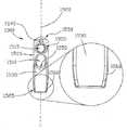
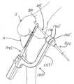
図8を参照すると、本発明の好ましい一形態を備える移植靱帯支持ブロック100が示
されている。移植靱帯支持ブロック100は、ボディ105と、移植孔110と、ボディ
105を通って延在する横断固定ピン孔115と、を備えている。このとき、移植孔11
0及び横断固定ピン孔115の両方は、ボディ105の長さ方向軸120に実質的に垂直
に延在しているのが好ましい。本発明の一つの好ましい形態では、移植孔110及び横断
固定ピン孔115は、ボディ105の直径を横断して延在し、移植孔110及び横断固定
ピン孔115は互いに実質的に平行に延びている。好ましくは、移植孔110は、横断固
定ピン孔115よりもボディ105の基端部125により接近して配置され、横断固定ピ
ン孔115は、移植孔110よりもボディ105の末端部130により接近して配置され
ている。本発明の一つの好ましい形態では、ボディ105の末端部は、
円形断面を持って
いる。該末端部は、楕円断面又は多角形断面(例えば、正方形、長方形又は三角形等)を
持つこともできる。一つの好ましい攻勢では、ボディ105の末端部は、ボディ105と
骨トンネルの壁との間の近接したインターフェースを提供するように、骨トンネルの直径
よりも僅かに小さくサイズが定められている。本発明の一つの好ましい形態では、ボディ
105の末端部130は、骨トンネルを通した移植靱帯支持ブロック100の前進を容易
にするようにテーパーが形成されている。本発明の好ましい形態では、ボディ105の基
端部は、移植孔110を通してループが形成され、そこから末端方向に延在する移植靱帯
のためのより多くの余地を提供するように、例えば135で示されたように、塑像されて
いる。ボディ105は、更に詳細を後述するように、ボディ105を適切な設置器具に取
り付けるための一対の凹部140も備えている。Referring to FIG. 8, a graft
Both the zero and transverse fixation pin holes 115 preferably extend substantially perpendicular to the
Has a circular cross section. The distal end can also have an elliptical cross section or a polygonal cross section (eg, square, rectangular, triangular, etc.). In one preferred offensive, the distal end of the
所望の場合には、移植靱帯支持ブロック100は、更に詳細が後述されるように、トウ
縫合糸を収容するための縫合糸孔145を備えていてもよい。If desired, the graft
更に加えて、所望の場合には、移植孔110の基端部は、移植孔110を通してループ
形成された移植靱帯のためのより外傷性が少ない受け表面を提供するように150で示さ
れるようにテーパーが形成されてもよく、及び/又は、横断固定ピン孔115の導入が横
断固定ピンの横断固定ピン孔115内への導入を容易にするように155で示されるよう
にテーパーがかけられていてもよい。In addition, if desired, the proximal end of the
ボディ105は、ポリマー、生体吸収性若しくは生体再構成可能材料、同種移植骨、金
属、セラミック、サンゴ、繊維複合物、前記したものの少なくとも1つを含む複合物等か
ら形成されてもよい。比較的強力な材料からボディ105を形成することにより、移植靱
帯を、ボディ105が比較的小さい場合又は孔110、115及び/又は145のうち1
つ以上がボディ105の周辺部にかなり接近して配置される場合でさえ、張力の作用下で
保持することができる。The
Even when two or more are placed in close proximity to the periphery of the
次に図9乃至図15を参照すると、移植靱帯支持ブロック100と関連して使用するこ
とができる設置器具200が示されている。設置器具200は、ホルダー205と、連係
するドリルガイド210とを備えている。Referring now to FIGS. 9-15, an
ホルダー205は、その末端部に一対の指部220を有し、その基端部にハンドル22
5を有するシャフト215を備える。指部220は、設置器具200が、移植靱帯支持ブ
ロック100の基端部に形成された凹部140(図8)内に選択的に嵌合することにより
、移植靱帯支持ブロック100と対をなして該ブロックを解放可能に保持することを可能
にする。図9乃至12及び図14を参照せよ。本質的には、指部220及び凹部140は
、雄/雌の接続関係を備え、所望ならば、雄部材と雌部材との配置を逆にしてもよく(即
ち、支持ブロック100に雄部、ホルダー205に雌部)、又は、代替種類の接続手段(
例えば、つかみ器)を使用することもできる。好ましくは、1つ以上の縫合糸ポスト22
7が、ハンドル225に隣接したシャフト215の基端部に形成される。縫合糸ポスト2
27は、更に詳細を後述するように、移植靱帯の2つの自由端部を設置器具に固定するこ
とを可能にする。ハンドル225は、設置器具200がユーザーにより便利に把持される
ことを可能にする。ハンドル225は、ポスト孔230を備える。ポスト孔230は、更
に詳細を後述するように、ドリルガイド210がホルダー205に解放可能に固定される
ことを可能にしている。The
A
For example, a grabber can be used. Preferably, one or more suture posts 22
7 is formed at the proximal end of the
27 allows the two free ends of the graft ligament to be secured to the placement instrument, as will be described in more detail below. The
ドリルガイド210は、張り出し部材235を備え、該張り出し部材は、その末端部2
45に形成されたねじ切りボア240(図14)と、その基端部260に形成されたスロ
ット250(図9)及びポスト255と、を有する。ポスト255の端部は、例えば26
5に示されるように、ねじが切られている。The
And a slot 250 (FIG. 9) and a
As shown in FIG.
張り出し部材の末端部245におけるねじ切りボア240(図14)は、ドリルスリー
ブ270を受け入れるようにサイズが定められている。ドリルスリーブ270は、その長
さに沿ったねじ切り部275を持ち、基端ヘッド部280で終わっている。ヘッド部28
0は、張り出し部材のねじ切りボア240内でドリルスリーブ270を手で回転させて張
り出し部材235の末端部245に対してドリルスリーブ270を移動させるため使用す
ることができる。管腔部285がドリルスリーブ270を通して延在する。The threaded bore 240 (FIG. 14) at the
0 can be used to move the
スロット250及びポスト255は、張り出し部材235をホルダー205に解放可能
に取り付けることを可能にしている。より詳しくは、張り出し部材235は、張り出し部
材のスロット250(図13及び図14)にホルダーのシャフト215を嵌合させ、ナッ
ト290をポスト255のねじ切り端部265へと締め付けることによって、ホルダー2
05に取り付けることができる。
05 can be attached.
後述されるように、移植靱帯支持ブロック100及び設置器具200は、横断固定ピン
と関連して使用することが意図されている。一つの好ましい横断固定ピン300が図16
に示されている。横断固定ピン300は、一般に、テーパーが付けられた末端部310で
終わっている中実シャフト305と、リブ付き(又は突起付き若しくはねじ切り)区分3
15と、を備えている。非円形ソケット320が、横断固定ピン300の基端部に形成さ
れ、該ソケットを用いて横断固定ピン300をドライバーによって係合させることができ
る。As described below, the graft
Is shown in The
15. A
以下、本発明に従って達成されるACL再構成を説明する。 The following describes the ACL reconstruction achieved in accordance with the present invention.
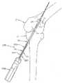
第1に、外科手術箇所は、例えば、損傷を受けたACLを取り除くこと等によって、移
植靱帯に対して準備される。次に、ガイドワイヤ400(図17)は、頸骨10を通して
掘削し、膝関節の内部へと至る。好ましくは、ガイドワイヤ400は、大腿骨15(図1
8)の底部に届かない位置で停止される。次に、カニューレ挿入式頸骨ドリル500(図
19)は、ガイドワイヤ400上に支持され、頸骨10を通って掘削し、膝関節の内部へ
と至る(図20)。次に、カニューレ挿入式頸骨ドリル500は、ガイドワイヤを下って
引き抜かれ(図21)、頸骨トンネル20を残す。First, the surgical site is prepared for the graft ligament, such as by removing damaged ACL. Next, the guide wire 400 (FIG. 17) is drilled through the
8) Stop at a position that does not reach the bottom. A cannulated tibia drill 500 (FIG. 19) is then supported on the
次に、ガイドワイヤ400は、大腿骨15の内部へと適切な距離、掘削される。所望の
場合には、ガイドワイヤ400は、以下に記載された理由のため、大腿骨15を貫通した
全行路に亘って、掘削してもよい(図22)。次に、カニューレ挿入式大腿骨ドリル60
0(例えば、エーコンドリル)は、ガイドワイヤ400(図22)に支持されて、膝関節
の内部を横断して、大腿骨トンネル20を通って通過され、大腿骨15内を掘削し、大腿
骨15の内部で停止される(図23)。カニューレ挿入式大腿骨ドリル600は、ガイド
ワイヤを戻って引き抜かれ、大腿骨トンネル25を残す(図24)。Next, the
0 (eg, an acon drill) is supported by guidewire 400 (FIG. 22), passed through the
次に、移植靱帯35は、移植孔110を通して移植靱帯の一端部を螺合することにより
、移植靱帯支持ブロック100に取り付けられ、次に移植靱帯支持ブロック100が、凹
部140に指部220を着座させることにより、シャフト215の末端部に取り付けられ
る。移植靱帯35の2つの自由端部は、例えば、移植靱帯35の2つの自由端部を通して
縫合糸70を通過させ、ポスト227を縫合するように縫合糸を固定する(例えば巻き付
ける)ことによって、ピンと張られるのが好ましい。この構成は、移植靱帯35の2つの
自由端部を制御することを援助し、移植靱帯支持ブロック100をホルダー205に保持
することを援助する。次に、設置器具200は、移植靱帯支持ブロック100を押し、よ
って移植靱帯35を、頸骨トンネル20(図25)を通して、膝関節の内部を横断して、
大腿骨トンネル(図26)へと押し上げる。Next, the
Push up into the femoral tunnel (FIG. 26).
所望の場合には、移植靱帯支持ブロック100及び移植靱帯35を頸骨トンネル20を
通して膝関節の内部を横断して大腿骨トンネル25へと推し進めるため必要となる力の全
ては、設置器具200を末端方向に押すことによって供給することができる。代替例とし
て、ガイドワイヤ400が大腿骨15を貫通して完全に掘削した場合(例えば、図22に
示されているような場合)、並びに、ガイドワイヤ400の基端部が縫合小穴(例えば、
図23及び図24に示される縫合小穴405等)を備えている場合、縫合糸は、移植靱帯
支持ブロック100及び移植靱帯35を所定位置まで引っ張ることを援助するため使用す
ることができる。より詳しくは、縫合糸700(図25)は、移植靱帯支持ブロック10
0内の縫合孔145を通して及びガイドワイヤ400の縫合小穴405を通してループ形
成されてもよく、大腿骨15の頂部から延在するガイドワイヤ400で末端方向に引っ張
ることにより、縫合糸700を、移植靱帯支持ブロック100及び移植靱帯35を牽引し
て適所へと持ち上げることを援助するように使用することができる(図26)。そのよう
な構成は、移植靱帯支持ブロック100及び移植靱帯35を適所へと押すため設置器具2
00により分配する必要がある力の量を減少させる。If desired, all of the forces required to propel the graft
With the
The
Reduce the amount of force that needs to be distributed by 00.
一旦、移植靱帯支持ブロック100及び移植靱帯35が適所へと押し進められたならば
(図26)、ドリルスリーブ270は、大腿骨15(図27)と緊密に係合した状態へと
進められる。この作用は、大腿骨15に対して設置器具200を安定化させる。次に、横
断トンネルドリル(図28)は、大腿骨15の横方向部分を通して、移植靱帯支持ブロッ
ク100内の横断固定ピン孔115を通して、大腿骨15の中間部分へと横断トンネル7
5を掘削するため使用される。この点において、移植靱帯支持ブロック100及び設置器
具200(及びこれによってドリルスリーブ270)の方位が、凹部140内の指部22
0の係合により調整されるという事実に起因して、移植靱帯支持ブロック100(図28
)内の横断固定ピン孔115を通って横断トンネルドリル800が正確且つ首尾一貫して
差し向けられることが認められる。Once the graft
Used for
Due to the fact that it is adjusted by zero engagement, the graft ligament support block 100 (FIG. 28).
It can be seen that the
一旦、横断トンネルドリル800が使用されて横断トンネル75を掘削したならば、横
断トンネルドリル800は除去される(図29)。ドリルスリーブ70は緩められ、張り
出し部材210がホルダー205から取り外される(図30)。ドライバー325に取り
付けられた横断固定ピン300は、横断トンネル75へと進められ、移植靱帯支持ブロッ
ク100内の横断固定ピン孔115を横切り(図31)、大腿骨トンネル25内の移植靱
帯支持ブロック100(及びこれによって移植靱帯35)を固定する。横断固定ピン30
0の区分315がリブ付き又は突起付き又はねじが切られているかのいずれかに応じて、
該横断固定ピンは、木槌でドライバーの基端部を叩くことにより又はドライバーを回転さ
せることにより、及び/又は、それらの両方により、ドライバー325により進めること
ができる。次に、ドライバー325が取り外される(図32)。次に、移植靱帯35の2
つの自由端部は、ハンドルの縫合糸ポスト227から脱着され、ホルダー205が引き離
される(図33)。この点において、移植靱帯支持ブロック100は、横断トンネル75
及び横断固定ピン孔115における横断固定ピン300の存在に起因してホルダー205
が引っ込められるとき、大腿骨トンネル25内の位置に保持されることが認められる。最
終的に、移植靱帯35の2つの自由端部は、頸骨10に固定され、これによって、ACL
再構成手続きを完了する。Once the
Depending on whether the 0
The transverse fixation pin can be advanced by the
One free end is detached from the
And the
It can be seen that when the is retracted, it is held in position within the
Complete the reconfiguration procedure.
上述した実施例では、横断固定ピン孔115(図8)は、ボディ105内に予め形成さ
れている。そのような構成は、一般に有利である。それは、移植靱帯支持ブロック100
が大腿骨トンネル内に配置された後、横断固定ピン300がボディ105を通って通過さ
れる前に、ボディ105を通して掘削する必要を無くすからである。更に加えて、横断固
定ピン孔115をボディ105内に予め形成することにより、横断固定ピン孔115は、
所望の形状を与えられる。例えば、それは、図8の155に示されるように、交差ピン孔
115への入口がテーパー形成されることを可能にし、横断固定ピン孔115において中
央横断固定ピン300を援助する。しかし、所望ならば、横断固定ピン孔115は、ボデ
ィ105内に予め形成されていなくてもよいことも理解されるべきである。代替例として
、手術時に、例えば、横断トンネルドリル800で横断トンネル75を形成するときボデ
ィ105を横切って掘削することにより、横断固定ピン孔115が自然位置に形成されて
もよい。横断固定ピン孔115が自然位置に形成されるべき場合、ボディ105が掘削可
能な材料から形成される必要があることは勿論である。更に加えて、横断固定ピン孔11
5が自然位置に形成されるべき場合、ボディ105は、比較的強固な材料から形成される
のが好ましい。横断固定ピン孔115の任意の置き間違え(即ち、中心からずれた配置)
がボディ105によって十分に許容されるからである。In the embodiment described above, the transverse fixing pin hole 115 (FIG. 8) is formed in the
This is because it is not necessary to dig through the
Given the desired shape. For example, it allows the entrance to the
When 5 is to be formed in the natural position, the
This is because this is sufficiently allowed by the
更に加えて、上記した実施例では、ボディ105の外側表面は、図8の135に示され
るように、大腿骨トンネル25内の移植靱帯と適合することを援助するように、移植孔1
10に近接して塑造される。図8では、135で実質的に平坦な表面を生成するように、
塑造が達成される。しかし、所望ならば、塑造は、例えば表面溝等の代替形状を提供する
ように達成することもできる。かくして、例えば、図34では、ボディ105は、移植孔
110と連通し且つ移植孔から基端方向に延在する一対の表面溝165を備えて示されて
いる。表面溝165は、移植靱帯が移植孔110から基端方向に延在するので、移植靱帯
の着座部分のための凹部を提供するようにサイズが定められている。In addition, in the above described embodiment, the outer surface of the
10 is molded in the vicinity. In FIG. 8, to produce a substantially flat surface at 135,
Plasticity is achieved. However, if desired, the plastic forming can also be accomplished to provide alternative shapes such as surface grooves. Thus, for example, in FIG. 34, the
また、上記した実施例では、ボディ105が、比較的滑らかな外側表面を有するものと
して示されている(例えば、図8参照)。しかし、所望ならば、ボディ105は、骨トン
ネル内でボディ105を安定化させるように、その側壁上に形成されたスパイク又はリブ
を有することができる。Also, in the above-described embodiment, the
更には、上記開示された実施例では、ドリルスリーブ270は、ねじ接続部(即ち、ド
リルスリーブ270の外側のねじ切り部275及び張り出し部材235のねじ切りボア2
40)を介して、張り出し部材235に移動可能に接続されている。この構成は、張り出
し部材235にドリルスリーブ270を移動可能に固定する簡単でコスト効果のある方法
を提供する。しかし、所望の場合には、他の種類の構成も使用することができる。例えば
、図35及び図36を参照すると、ドリルスリーブ270は、張り出し部材235におい
てねじが切っていないボア240Aを通して摺動する、滑らか又はリブ付き又は丸みを帯
びた(例えば、こぶ付き)外部275Aを持つことができる。係止ピン235Aは、ドリ
ルスリーブ270との係合状態へと選択的に前進可能であり(ねじ切りボア235Bを通
して)、これによりドリルスリーブを張り出し部材に選択的に係止する。ドリルスリーブ
270を張り出し部材235に選択的に係止するための更に他の可能となる構成は、掘削
及びドリルスリーブの技術分野の当業者には明らかである。Furthermore, in the disclosed embodiment, the
40) through the projecting
また、上記開示された実施例では、ドリルガイド210は、ポスト255及び締め付け
ナット290を介してホルダー205に解放可能に固定されるものとして示されている(
例えば、図14参照)。しかし、他の種類の接続部(例えば、「迅速」解放式機構)も、
ドリルガイド210をホルダー205に解放可能に固定するため使用することもできるこ
とを理解することができる。Also, in the disclosed embodiment, the
For example, see FIG. However, other types of connections (eg, “quick” release mechanisms)
It can be appreciated that the
移植靱帯支持ブロック100及び移植靱帯35が大腿骨トンネル25内に配置される前
に横断トンネル75を形成することも可能である。より詳しくは、一つの可能な構成にお
いて、リーマードリルガイド200A(図37)を使用することもできる。リーマードリ
ルガイド200Aは、後述されたものを除いて、上述された設置器具200と実質的に同
一である。より詳しくは、リーマードリルガイド200Aは、リーマー205A及びドリ
ルガイド210を備える。リーマー205Aは、横断孔220Bを貫通させたその末端部
で円柱要素220A(図37及び図38)を持ち、ホルダー205上に好ましく設けられ
た縫合糸ポスト227を省略するという天を除いて、上述したホルダー205と実質的に
同一である。リーマー205Aは、(i)その円柱要素220Aが大腿骨トンネル25の
直径に略等しい直径を有し、(ii)ドリルガイド210がリーマー205Aに取り付け
られているとき、ドリルスリーブ270内の管腔部285がリーマー205Aの横断孔2
20Bと整列するように構成されている。It is also possible to form a
It is configured to align with 20B.
移植靱帯支持ブロック100、ホルダー205及びリーマードリルガイド200Aは、
次の通り、ACL再構成を達成するため使用することができる。The graft
It can be used to achieve ACL reconstruction as follows.
最初に、例えば、損傷を受けたACLを取り除くこと等によって、手術箇所が移植靱帯
のために準備される。次に、ガイドワイヤ400(図17)は、膝関節の内部を横切って
、頸骨10を通して掘削される。好ましくは、ガイドワイヤ400は、大腿骨15の底部
と係合するに及ばないところで停止される(図18)。次に、カニューレ挿入式頸骨ドリ
ル500(図19)がガイドワイヤに沿って下方に引き抜かれ(図21)、頸骨トンネル
20を残す。Initially, a surgical site is prepared for the graft ligament, such as by removing the damaged ACL. Next, a guidewire 400 (FIG. 17) is drilled through the
次に、ガイドワイヤ400は、大腿骨15の内部へと適切な距離だけ掘削する。次に、
カニューレ挿入式大腿骨ドリル600(例えば、図22に示される種類のエーコンドリル
)が、ガイドワイヤ400に支持され、頸骨トンネル20を通して通過され、膝関節の内
部を横切り、次に、大腿骨15内へと掘削され、大腿骨15の内部内で停止される。次に
、カニューレ挿入式大腿骨ドリル600は、ガイドワイヤに沿って下方に引き抜かれ、大
腿骨トンネル25を残し、最後にガイドワイヤ400が引き抜かれる(図39参照)。The
A cannulated femoral drill 600 (e.g., an akon drill of the type shown in FIG. 22) is supported on
次に、リーマードリルガイド200Aは、その円柱要素220Aが、頸骨トンネル20
を通って膝の内部を横切り、大腿骨トンネル25内へと上方に進められるように、押し進
められる。この点において、リーマードリルガイド200Aが頸骨トンネル20及び大腿
骨トンネル25を通って進められるとき、その円柱要素220Aが、骨トンネルの両方を
拡径し、内部にある破片を一掃することが理解されるべきである。Next, the
And is pushed forward so that it can be advanced through the inside of the knee and up into the
一旦、リーマードリルガイド200Aが適所へと押し進められたならば、ドリルスリー
ブ270は、大腿骨15との緊密な係合状態へと進められる。この作用は、大腿骨15に
対するリーマードリルガイド200Aを安定化させる。次に、横断トンネルドリル800
(図40)は、大腿骨15の横方向部分を通して、円柱要素220Aの横断孔220Bを
通して、大腿骨15の中間部分へと横断トンネル75を掘削するため使用される。この点
において、円柱要素220A及びドリルスリーブ270の相対配置がリーマー205Aと
のドリルガイド210の予め定義された係合状態により調整されるという事実に起因して
、横断トンネルドリル800は円柱要素220A(図40)内の横断孔220Bを通って
正確且つ首尾一貫して方向付けられることが理解される。Once the
(FIG. 40) is used to drill a
一旦、横断トンネルドリル800が横断トンネル75を掘削するため使用されたならば
、横断トンネルドリル800は取り外される。次に、ドリルスリーブ270が緩められ、
リーマードリルガイド200Aが手術箇所から引き抜けられる(図41)。Once the
The
次に、移植靱帯35は、移植靱帯の一方の端部を移植孔110を通して螺合することに
より移植靱帯支持ブロック100に取り付けられ、次に、移植靱帯支持ブロック100は
、凹部140内に指部220を着座させることにより、シャフト215の末端部に取り付
けられる。移植靱帯35の2つの自由端部は、移植靱帯35の2つの自由端部を通して縫
合糸70を通過させ、次に、これらの縫合糸を縫合糸ポスト227に固定することにより
(例えば、巻き付けることにより)、ピンと張った状態に保持されるのが好ましい。この
構成は、移植靱帯35の2つの自由端部を制御することを援助し、移植靱帯支持ブロック
100をホルダー205に保持させる。次に、ホルダー205は、移植靱帯支持ブロック
100を押し、よって、移植靱帯35を押し、頸骨トンネル20を通して、膝関節の内部
を横切り、大腿骨トンネル25(図42)へと押し上げるため使用される。移植靱帯支持
ブロックが、頸骨トンネル25内を前進されたとき、又は、それが頸骨トンネル25内を
適切な距離だけ前進された後、それは、横断固定ピン孔115を横断トンネル75と整列
させるように、ハンドル225を必要に応じて回転させることにより必要に応じて回転さ
れる。そのような整列は、ハンドル225上に整列マーカー(例えば、図43に示された
整列マーカー225A)を提供することにより容易にすることができる。Next, the
ドライバーに取り付けられた横断固定ピン300は、横断トンネル75へと進められ、
移植靱帯支持ブロック100(図44)内の横断固定ピン孔115を横切り、これによっ
て大腿骨トンネル25内に移植靱帯支持ブロック100(及びこれにより移植靱帯35)
を固定する。次に、ドライバー325が取り外される。次に、移植靱帯35の2つの自由
端部が、ハンドルの縫合糸ポスト227から脱着され、ホルダー205が引き抜かれる。
この点において、移植靱帯支持ブロック100が、ホルダー205が、横断トンネル75
内の横断固定ピン300及び横断固定ピン孔115の存在に起因して引き抜かれるとき、
大腿骨トンネル25内の適所に保持される。最終的には、移植靱帯35の2つの自由端部
は、頸骨10に固定され、これによりACL再構成処置を完了する。The
The transverse
To fix. Next, the
In this regard, the graft
When pulled out due to the presence of the
It is held in place within the
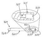
次に、図45及び図46を参照すると、本発明の一つの好ましい形態を備える、修正移
植靱帯支持ブロック1500が示されている。移植靱帯支持ブロック1500は、ボディ
1505と、移植孔1510と、ボディ1505を通って延在する横断固定ピン孔151
5とを備え、移植孔1510及び横断固定ピン孔1515の両方がボディ1505の長さ
方向軸1520に実質的に垂直な状態となっているのが好ましい。本発明の一つの好まし
い形態では、移植孔1510及び横断固定ピン孔1515が互いに実質的に平行な状態で
、ボディ1505を横切って直径方向に延在している。好ましくは、移植孔1510は、
横断固定ピン孔1515よりもボディ1505の基端部1525により接近して配置され
、横断固定ピン孔1515が、移植孔1510よりもボディ1505の末端部1530に
接近して配置される。本発明の一つの好ましい形態では、ボディ1505の末端部は、円
形断面を有する。それは、楕円断面又は多角形断面(例えば、正方形、長方形又は三角形
等)を持っていてもよい。一つの好ましい構成では、ボディ1505の末端部は、ボディ
1505と骨トンネルの壁との間に接近したインターフェースを提供するように、骨トン
ネルの直径よりも僅かに小さいサイズの断面を有する。本発明の一つの好ましい形態では
、ボディ1505の末端部1530は、骨トンネルを通る移植靱帯支持ブロック100の
前進を容易にするようにテーパーが形成されている。本発明の好ましい形態では、ボディ
1505の基端部は、移植孔1510を通ってループを形成し、そこから末端方向に延在
する移植靱帯のためのより多い余空間を提供するように、例えば、1535に示されるよ
うに、塑像される。ボディ1505は、ボディ1505を適切な設置器具に取り付けるた
めの1つ以上の凹部(図示しないが、好ましくはボディ(105)に設けられた凹部14
0に類似するか又は相似している)を更に備えている。45 and 46, there is shown a modified graft
5 and both the
The transverse
Is similar to or similar to 0).
所望ならば、移植靱帯支持ブロック1500は、詳細を更に後述するように、トウ縫合
糸を受け入れるための縫合糸孔1545を更に備えている。If desired, the graft
更に加えて、所望ならば、移植孔1510の基端部は、移植孔1510を通ってループ
がかけられた移植靱帯のためのより外傷性が少ないベアリング表面を提供するように15
50で示されるようにテーパーが形成されてもよく、及び/又は、横断固定ピン孔151
5への導入を容易にするように1555で示されるようにテーパーが形成されてもよい。In addition, if desired, the proximal end of the
The taper may be formed as shown at 50 and / or the transverse fixation pin hole 151.
A taper may be formed as shown at 1555 to facilitate introduction into 5.
ボディ1505は、ポリマー、生体吸収性又は生体再構成可能材料、同種移植片骨、金
属、セラミック、サンゴ、繊維複合物、前記した物のうち少なくとも1つ等を含む複合物
から形成することができる。比較的強力な材料からボディ1505を成形することにより
、移植靱帯は、ボディ1505が比較的小さい場合でさえ又は孔1510、1515及び
/又は1545のうち一つ以上がボディ1505の周囲部にかなり接近した状態で配置さ
れる場合に、張力の作用下で保持することができる。The
図45、図46A及び図46Bを更に参照すると、ボディ1505の基端部1525に
設けられたテーパー形成部分1560が示されている。テーパー形成部分1560は、例
えば操作が共通の修正のため同じものが必要とされる場合に、移植ブロック1505の骨
トンネルからの引き抜きを容易にする。これは、正方形のコーナーを備えた他の設計でが
、ボディが骨トンネルから基端方向に引き抜かれる場合に骨トンネル内で拘束する傾向が
あるため、この点で有利となっている。With further reference to FIGS. 45, 46A and 46B, a tapered
ここで、図46A及び図46Bを参照すると、移植靱帯の幅に実質的に等しい長さX(
図46A)を備えた移植孔1510を有するボディ1505が示されている。移植孔15
10は、ボディ105の移植孔110の長さYよりも短い開口部を提供し(図46B)、
トンネル壁と移植靱帯との接触を増大させる。Referring now to FIGS. 46A and 46B, a length X (substantially equal to the width of the graft ligament.
A
10 provides an opening shorter than the length Y of the
Increase contact between tunnel wall and graft ligament.
本発明の好ましい実施例では、骨トンネル内で移植靱帯を固定するための方法が提供さ
れる。本方法は、移植靱帯の与えられた幅に実質的に等しいサイズの移植孔を備えた移植
靱帯支持ブロックを選択する第1の工程を備えている。本方法は、移植靱帯支持ブロック
内の移植孔を通して移植靱帯をループ形成する工程を備えている。本方法は、移植靱帯支
持ブロックを骨トンネル内に前進させる更なる工程を備える。本方法は、横断トンネルが
移植靱帯支持ブロック内の横断固定ピン孔と整列した状態で、ホスト骨に横断トンネルを
形成する工程を備える。本方法の最終的な工程は、ホスト骨内の横断トンネルに沿って移
植靱帯支持ブロック内の横断固定ピン孔内へと横断固定ピンを押し進めることによって、
移植靱帯支持ブロックを骨トンネル内にピン止めする工程を備える。In a preferred embodiment of the present invention, a method is provided for securing a graft ligament within a bone tunnel. The method includes a first step of selecting a graft ligament support block with a graft hole of a size substantially equal to a given width of the graft ligament. The method includes looping the graft ligament through the graft hole in the graft ligament support block. The method comprises the further step of advancing the graft ligament support block into the bone tunnel. The method comprises forming a transverse tunnel in the host bone with the transverse tunnel aligned with a transverse fixation pin hole in the graft ligament support block. The final step of the method is to push the transverse fixation pin along the transverse tunnel in the host bone and into the transverse fixation pin hole in the graft ligament support block,
Pinning the graft ligament support block into the bone tunnel.
本発明の別の好ましい実施例では、骨トンネル内に移植靱帯を固定するための方法が提
供される。本方法は、ホスト骨内に横断トンネルを形成する工程を備える。本方法は、移
植靱帯の与えられた幅に実質的に等しくサイズが定められた移植孔を備えた移植靱帯支持
ブロックを選択する工程を備えている。本方法は、移植靱帯支持ブロック内に移植孔を通
して移植靱帯をループ形成する工程も備えている。移植靱帯支持ブロックは、移植靱帯支
持ブロック内の横断固定ピン孔が横断トンネルと整列するように骨トンネル内に進められ
る。最終的な工程は、ホスト骨内の横断トンネルに沿って横断固定ピンを、移植靱帯支持
ブロック内の横断固定ピン孔へと押し進めることによって、骨トンネル内に移植靱帯支持
ブロックをピン止めする工程を備えている。In another preferred embodiment of the present invention, a method is provided for securing a graft ligament within a bone tunnel. The method includes forming a transverse tunnel in the host bone. The method includes selecting a graft ligament support block having a graft hole sized substantially equal to a given width of the graft ligament. The method also includes looping the graft ligament through the graft hole in the graft ligament support block. The graft ligament support block is advanced into the bone tunnel such that the transverse fixation pin holes in the graft ligament support block are aligned with the transverse tunnel. The final step is to pin the graft ligament support block in the bone tunnel by pushing the transverse fixation pin along the transverse tunnel in the host bone into the transverse fixation pin hole in the graft ligament support block. I have.
ここで図47及び図48を参照すると、本発明の好ましい実施例では、上述された横断
固定ピン300(図30)と類似の態様で使用するように構成された取り外し可能な横断
固定ピン1600(図47)が示されている。取り外し可能な横断固定ピン1600(図
47)は、概して、テーパー形成された末端部1610で終わっている中実シャフト16
05と、リブ付き(突起付き又はねじ切り)区分1615と、を備えている。ソケット1
620は、取り外し可能な横断固定ピン1600の基端部に形成され、これにより横断固
定ピン1600をドライバーにより係合することができる。ソケット1620は、回転式
ドライバー(例えば、六角ドライバー)又はマレット式ドライバーを収容するように構成
することができる。ソケット1620は、内部に形成された内部タップ孔1625を更に
備える。内部タップ孔1625は、横断骨トンネルから取り外し可能な固定ピン1600
の取り外しを援助するように、引き抜き器具1630(図48)と係合するように構成さ
れている。Referring now to FIGS. 47 and 48, in a preferred embodiment of the present invention, a removable transverse fixation pin 1600 (configured for use in a manner similar to the transverse fixation pin 300 (FIG. 30) described above. FIG. 47) is shown. The removable transverse locking pin 1600 (FIG. 47) generally has a solid shaft 16 that terminates in a
05 and a ribbed (protruded or threaded)
620 is formed at the proximal end of the removable
Is configured to engage with a withdrawal device 1630 (FIG. 48) to assist in the removal.
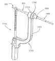
引き抜き器具1630は、概して、一方の端部にハンドル1640を有し、他方の端部
にねじ切り突起部1645を有するシャフト1635を備えている。ねじ切り突起部16
45は、取り外し可能な固定ピン1600内に形成された内部タップ孔1625と螺合す
るように構成されている。ねじ切り突起部1645が内部タップ孔1625に確実に嵌合
されるとき、取り外し可能な横断固定ピン1600を、ハンドル1640に適切な力を印
加することにより骨トンネルから引き抜くことができる。The
45 is configured to be screwed into an
本発明の好ましい実施例では、骨トンネル内で移植靱帯を修正するための方法が提供さ
れる。本方法は、取り外し器具を横断固定ピンの内部タップ孔と係合させる工程を備える
。本方法は、内部タップ孔と係合した取り外し器具を用いて骨トンネルから横断固定ピン
を引き抜く工程を更に備える。本方法は、骨トンネル内に移植靱帯支持ブロックを再配置
する更なる工程を備えている。本方法は、ホスト骨内の横断トンネルに沿って横断固定ピ
ンを、移植靱帯支持ブロック内の横断ピン孔内に押し進めることにより骨トンネル内で移
植靱帯支持ブロックをピン止めする最終的な工程を備えている。In a preferred embodiment of the present invention, a method is provided for modifying a graft ligament within a bone tunnel. The method comprises the step of engaging the removal tool with the internal tap hole of the transverse fixation pin. The method further comprises withdrawing the transverse fixation pin from the bone tunnel using a removal instrument engaged with the internal tap hole. The method comprises the further step of repositioning the graft ligament support block within the bone tunnel. The method comprises the final step of pinning the graft ligament support block within the bone tunnel by pushing the transverse fixation pin along the transverse tunnel in the host bone and into the transverse pin hole in the graft ligament support block. ing.
ここで、図49を参照すると、本発明の好ましい実施例に係る、その末端部の第1の長
さに沿った幅狭い切削部分1710と、幅狭い切削部分1710の基端方向に第2の長さ
に沿った幅広い切削部分1715と、幅狭い切削部分1710及び幅広い切削部分171
5の連結部に形成された不連続部分1720と、を備えたシャフト1705を有する段付
き横断トンネルドリル1700が示されている。49, in accordance with a preferred embodiment of the present invention, a
Shown is a stepped
ここで、図50を参照すると、段付き横断トンネルドリル1700は、大腿骨15の横
方向部分を通して、骨トンネル25の一部分を通して、上述されたような大腿骨15の中
間部分内へと段付き横断トンネル1725(図50)を掘削するように使用される。横断
トンネル1725は、段付き横断トンネルドリル1700の幅狭い切削部分1710及び
幅広い切削部分1715に各々対応する、幅狭い部分1730及び幅広い部分1735を
備えている。横断トンネル1725内の段付き部分(図示せず)は、横断トンネル172
5内の段付き部分(図示せず)は、横断トンネルピン(図示せず)の前進を停止するため
環状肩部を提供する。Referring now to FIG. 50, a stepped
A stepped portion (not shown) in 5 provides an annular shoulder to stop advancement of the transverse tunnel pin (not shown).
本発明の好ましい実施例(図示せず)では、段付き横断トンネルドリル1700の一部
分のプロフィールを有する段付き固定ピンが提供される。段付き固定ピンは、その末端部
の幅狭い部分と、その基端部の幅広い部分との間で形成された環状肩部を備えて構成され
るのが好ましい。環状肩部は、横断トンネル1725の幅狭い部分1730内の段付き固
定ピンの幅狭い部分と、断トンネル1725の幅広い部分1735内の段付き固定ピンの
幅広い部分とを位置決めするように、横断トンネル1725内で既知の距離の所定位置で
段付き固定ピンを着座させることを可能にする。In a preferred embodiment of the present invention (not shown), a stepped locking pin having a profile of a portion of a stepped
本発明の好ましい実施例では、骨トンネル内に移植靱帯を固定するための方法が提供さ
れる。本方法は、移植靱帯を移植靱帯支持ブロック(図示せず)内の移植孔を通してルー
プ形成する工程を備えている。本方法は、移植靱帯支持ブロックを骨トンネル25内へと
推し進める工程を更に備える。本方法は、段付き横断トンネル1725(図50)が移植
靱帯支持ブロック内の横断固定ピン孔(図示せず)と整列した状態で、段付き横断トンネ
ルドリル1700(図49)でホスト骨15内に段付き横断トンネル1725(図50)
を形成する工程も備えている。本方法は、ホスト骨15内の横断トンネル1725に沿っ
て段付き横断固定ピン(図示せず)を移植靱帯支持ブロック(図示せず)の横断固定ピン
孔(図示せず)内へと押し進めることによって、骨トンネル25内で移植靱帯支持ブロッ
クをピン止めする最終的な工程を備えている。In a preferred embodiment of the present invention, a method is provided for securing a graft ligament within a bone tunnel. The method includes looping the graft ligament through a graft hole in a graft ligament support block (not shown). The method further comprises advancing the graft ligament support block into the
The process of forming is also provided. The method pushes a stepped transverse fixation pin (not shown) along a
本発明の好ましい実施例では、設置器具は、ホスト骨15(図50)内に段付き横断ト
ンネル1725を形成する工程の前に、移植靱帯支持ブロックを骨トンネル内へと進める
ために使用される。好ましくは、設置器具は、ホスト骨に段付き横断トンネルを形成する
ため段付き横断トンネルドリルと共に使用される。In the preferred embodiment of the present invention, the placement instrument is used to advance the graft ligament support block into the bone tunnel prior to the step of forming the stepped
本発明の別の好ましい実施例では、トウ縫合糸は、ホスト骨15(図50)内に段付き
横断トンネル1725を形成する工程の前に、移植靱帯支持ブロックを骨トンネル内へと
進めるために使用される。In another preferred embodiment of the present invention, the tow suture is used to advance the graft ligament support block into the bone tunnel prior to the step of forming a stepped
本発明の好ましい実施例では、骨トンネル内に移植靱帯を固定するための別の方法が提
供される。本方法は、段付き横断トンネルドリル1700(図49)を用いてホスト骨1
5内に段付き横断トンネルドリル1725(図50)を形成する第1の工程を備える。本
方法は、移植靱帯支持ブロック内の移植孔を通して移植靱帯をループ形成する次に続く工程を備えている。本工程の次に、移植靱帯支持ブロック(図示せず)内の横断固定ピン孔が段付き横断トンネル1725と整列されるように、移植靱帯支持ブロックを骨トンネル25内に進める工程が実行される。本方法は、ホスト骨内の段付き横断トンネル1725に沿って段付き横断固定ピン(図示せず)を、移植靱帯支持ブロック(図示せず)の横断固定ピン孔(図示せず)内へと進めることによって、骨トンネル25内に移植靱帯支持ブロックをピン止めする最終的な工程を備えている。In a preferred embodiment of the present invention, another method for securing a graft ligament within a bone tunnel is provided. The method uses a stepped transverse tunnel drill 1700 (FIG. 49) to
5 includes a first step of forming a stepped transverse tunnel drill 1725 (FIG. 50) in the interior. The method comprises a subsequent step of looping the graft ligament through the graft hole in the graft ligament support block. Following this step, the step of advancing the graft ligament support block into the
本発明の好ましい実施例(図示せず)では、段付き横断トンネルを形成し、移植靱帯を
移植孔を通してループ形成する工程に引き続いて、移植靱帯支持ブロックを骨トンネル内
に進めるために設置器具が使用される。In a preferred embodiment of the present invention (not shown), following the steps of forming a stepped transverse tunnel and looping the graft ligament through the graft hole, an installation tool is provided to advance the graft ligament support block into the bone tunnel. used.
ここで、図51A、51B及び52を参照すると、本発明の好ましい実施例に係る、全
体としてホルダー1745及びこれに連係するドリルガイド1750を備える、較正され
た移植靱帯再構成システム1740(図52)が示されている。Referring now to FIGS. 51A, 51B and 52, a calibrated graft ligament reconstruction system 1740 (FIG. 52) comprising a
ドリルガイド1750は、上述されたドリルガイド210に類似した構成を有する。好
ましくは、ドリルガイド1750は、その末端部1765に形成され且つドリルスリーブ
1770を内部に収容するようにサイズが定められた滑らかなボア1760を有する張り
出し部材1755を備える。ドリルスリーブ1770上に配置された第1の組の深さマー
カー1775は、ドリルスリーブ1770の末端先端部1780から大腿骨15内の予め
選択された部分までの距離を表示するように構成されている。好ましくは、深さマーカー
1775は、滑らかなボア1760の基端開口部1785に対する位置で読み取られる。The
ここで、図51B及び52を参照すると、本発明の好ましい実施例に係る、第2の組の
深さマーカー1790を有する段付き横断ドリル1700が示されている。深さマーカー
1790は、大腿骨15内の予め選択された位置までの距離を表示するため構成されてい
る。好ましくは、深さマーカー1790は、ドリルスリーブ1770の基端開口部179
5(図52)に対する位置で読み取られる。51B and 52, there is shown a stepped
5 (FIG. 52).
本発明の好ましい実施例では、骨トンネル内に移植靱帯を固定するための方法が開示さ
れる。本方法は、移植靱帯支持ブロック内で移植孔を通して移植靱帯をループ形成する第
1の工程を備える。本方法は、移植靱帯支持ブロックを骨トンネル内へと進める次の工程
を備えている。この工程の次に、移植靱帯支持ブロックに取り付けられたドリルガイドを
配置する工程が実行される。このとき、ドリルガイドは、張り出し部材と、該張り出し部
材に移動可能に取り付けられたドリルスリーブと、を有し、該ドリルスリーブは深さマー
カーを有している。本方法は、ドリルスリーブ及び張り出し部材を用いて、ドリルスリー
ブを張り出し部材内で骨トンネルに向って移動させ、ドリルスリーブ上の深さマーカーを
読み取ることによって、適切な横断トンネル深さを決定する工程を更に備えている。本方
法は、横断トンネルが移植靱帯支持ブロック内の横断固定ピン孔と整列した状態で、横断
トンネルドリルで、配置されたマーカーに従った与えられた深さまで掘削することにより
、適切な横断トンネル深さへとホスト骨内に横断トンネルを形成する工程を備えている。
本方法は、横断固定ピンをホスト骨内の横断トンネルに沿って移植靱帯支持ブロック内の
横断固定ピン孔内へと進めることによって骨トンネル内に移植靱帯支持ブロックをピン止
めする最終的な工程を備えている。In a preferred embodiment of the present invention, a method for securing a graft ligament within a bone tunnel is disclosed. The method includes a first step of looping the graft ligament through the graft hole in the graft ligament support block. The method includes the following steps of advancing the graft ligament support block into the bone tunnel. Following this step, a step of placing a drill guide attached to the graft ligament support block is performed. At this time, the drill guide has an overhang member and a drill sleeve movably attached to the overhang member, and the drill sleeve has a depth marker. The method uses a drill sleeve and an overhang member to determine an appropriate transverse tunnel depth by moving the drill sleeve within the overhang member toward the bone tunnel and reading a depth marker on the drill sleeve. Is further provided. With this method, with the transverse tunnel aligned with the transverse fixation pin hole in the graft ligament support block, the appropriate transverse tunnel depth is drilled with a transverse tunnel drill to a given depth according to the placed marker. A step of forming a transverse tunnel in the host bone is also provided.
The method includes the final step of pinning the graft ligament support block in the bone tunnel by advancing the transverse fixation pin along the transverse tunnel in the host bone and into the transverse fixation pin hole in the graft ligament support block. I have.
本発明の別の好ましい実施例では、骨トンネルに移植靱帯を固定するための方法が開示
されている。本方法は、移植靱帯支持ブロックに取り付けられたドリルガイドを位置決め
する最初の工程を備えている。このとき、ドリルガイドは、張り出し部材と、該張り出し
部材に移動可能に取り付けられたドリルスリーブと、を有し、該ドリルスリーブは深さマ
ーカーを有している。本方法は、ドリルスリーブ及び張り出し部材を用いて、ドリルスリ
ーブを張り出し部材内で骨トンネルに向って移動させ、ドリルスリーブ上の深さマーカー
を読み取ることによって、適切な横断トンネル深さを決定する次の工程を更に備えている
。本方法は、横断トンネルドリルで、配置されたマーカーに従った与えられた深さまで掘
削することにより、適切な横断トンネル深さへとホスト骨内に横断トンネルを形成する工
程を備えている。本方法は、移植靱帯支持ブロック内の移植孔を通して移植靱帯をループ
形成する工程を呼び出す。本方法は、移植靱帯支持ブロック内の横断固定ピン孔が横断ト
ンネルと整列するように、移植靱帯支持ブロックを骨トンネル内へと進める工程を備えて
いる。本方法は、横断固定ピンをホスト骨内の横断トンネルに沿って移植靱帯支持ブロッ
ク内の横断固定ピン孔内へと進めることによって骨トンネル内に移植靱帯支持ブロックを
ピン止めする最終的な工程を備えている。In another preferred embodiment of the present invention, a method for securing a graft ligament to a bone tunnel is disclosed. The method includes an initial step of positioning a drill guide attached to the graft ligament support block. At this time, the drill guide has an overhang member and a drill sleeve movably attached to the overhang member, and the drill sleeve has a depth marker. The method uses the drill sleeve and the overhang member to determine the appropriate transverse tunnel depth by moving the drill sleeve within the overhang member toward the bone tunnel and reading the depth marker on the drill sleeve. The process is further provided. The method comprises forming a transverse tunnel in the host bone to the appropriate transverse tunnel depth by drilling with a transverse tunnel drill to a given depth according to the placed marker. The method invokes the step of looping the graft ligament through the graft hole in the graft ligament support block. The method comprises advancing the graft ligament support block into the bone tunnel such that a transverse fixation pin hole in the graft ligament support block is aligned with the transverse tunnel. The method includes the final step of pinning the graft ligament support block in the bone tunnel by advancing the transverse fixation pin along the transverse tunnel in the host bone and into the transverse fixation pin hole in the graft ligament support block. I have.
図53及び図54を参照すると、本発明の好ましい実施例に係る、停止要素1805が
配置された、深さ制限横断トンネルドリル1800が示されている。ドリル1800は、
整形外科分野で知られた多数の先端部の任意の一つ、例えば、標準縦溝付き先端部、トロ
カール先端部、及び、スペード先端部等を持ち得る。横断トンネルドリル1800の末端
先端部1810の大腿骨15への貫通深さを制限するように、停止要素1805は、横断
トンネルドリル1800を制限する深さの長さに沿った位置に配置されている(図54)
。停止要素1805は、基端開口部1785に隣接した末端部1765で張り出し部材1
755と係合することにより横断トンネルドリル1800の末端貫通を制限し、末端部1
815のみが通過することを可能にする。53 and 54, there is shown a depth limited
It can have any one of a number of tips known in the orthopedic field, such as a standard fluted tip, a trocar tip, a spade tip, and the like.
. The
Engage with 755 to limit the end penetration of
Allows only 815 to pass.
本発明の好ましい実施例では、停止要素1805は、横断トンネルドリル1800を深
さ制限する一部分に沿って、調整可能に又は固定して位置決めされ、更に、横断トンネル
ドリル1800の大腿骨15への貫通の深さを選択的に決定するように係止装置を更に備
えている。In a preferred embodiment of the present invention, the
ここで、図55及び図56を参照すると、本発明の好ましい実施例に係る、一連の深さ
ゲージ標識1905を形成した深さゲージ1900が示されている。深さゲージ1900
は、大腿骨15への挿入及び適切な配置のためその末端部1915で横断固定ピン191
0と係合するように構成されている(図56)。深さゲージ1900の深さゲージ標識1
905は、末端部1915の位置を指し示し、よって、大腿骨15内の深さゲージの基端
部を示している。好ましくは、深さゲージ標識1905は、挿入体1900が通過してい
るドリルスリーブ1775の基端開口部1795に対する位置で読み込まれる。Referring now to FIGS. 55 and 56, there is shown a
The transverse fixation pin 191 at its
It is configured to engage 0 (FIG. 56).
905 indicates the position of the
図52を参照すると、本発明の好ましい実施例に係る、骨トンネル内に移植靱帯を固定
するための方法が開示されている。本方法は、移植靱帯支持ブロック内の移植孔を通して
移植靱帯のループを形成する第1の工程を備える。この工程には、移植靱帯支持ブロック
を骨トンネル内へと進める工程が続く。本方法は、張り出し部材1755に対するドリル
スリーブ1770上の深さマーカー1775の位置を読み取ることによって、適切な横断
トンネル深さを決定する更なる工程を備えている。本方法は、横断トンネルを適切な横断
トンネル深さにまで掘削するように、深さマーカー1790を有する横断トンネルドリル
1770を使用してホスト骨内で横断トンネルを形成し、移植靱帯支持ブロック内で横断
固定ピン孔が整列される引き続く工程を備えている。本方法は、ドリルスリーブ1770
上の深さマーカー1775により決定される適切な横断トンネル深さに基づいて横断固定
ピンを選択し、選択された横断固定ピンをホスト骨内の横断トンネルに沿って移植靱帯支
持ブロックの横断固定ピン孔内へと進めることによって、移植靱帯支持ブロックを骨トン
ネル内でピン止めする最終工程を備えている。Referring to FIG. 52, a method for securing a graft ligament in a bone tunnel according to a preferred embodiment of the present invention is disclosed. The method includes a first step of forming a graft ligament loop through a graft hole in a graft ligament support block. This step is followed by advancing the graft ligament support block into the bone tunnel. The method comprises the further step of determining the appropriate transverse tunnel depth by reading the position of the
Select a transverse fixation pin based on the appropriate transverse tunnel depth determined by the
図52を更に参照すると、本発明の好ましい実施例に係る、骨トンネル内に移植靱帯を
固定するための方法が開示されている。本方法は、ドリルスリーブ1770上の深さマー
カー1775の張り出し部材1755に対する位置を読み取ることによって、適切な横断
トンネル深さを決定する最初の工程を備えている。本方法は、横断トンネルを適切な横断
トンネル深さにまで掘削するように、深さマーカー1790を有する横断トンネルドリル
1700を使用してホスト骨内に横断トンネルを形成する更なる工程を備えている。本方
法は、移植靱帯支持ブロック内の移植孔を通して移植靱帯をループ形成する次に続く皇帝
を備えている。この工程に続いて、移植靱帯支持ブロック内の横断固定ピン孔が横断トン
ネルと整列するように骨トンネル内へと移植靱帯支持ブロックを進める工程が実行される
。本方法は、ドリルスリーブ1770上の深さマーカー1775により決定される適切な
横断トンネル深さに基づいて横断固定ピンを選択し、横断固定ピンをホスト骨内の横断ト
ンネルに沿って移植靱帯支持ブロックの横断固定ピン孔内に進めることによって骨トンネ
ル内に移植靱帯支持ブロックをピン止めする最終工程を備えている。With further reference to FIG. 52, a method for securing a graft ligament in a bone tunnel according to a preferred embodiment of the present invention is disclosed. The method includes an initial step of determining an appropriate transverse tunnel depth by reading the position of the
ここで、図53及び図54を参照すると、本発明の好ましい実施例に係る、骨トンネル
内に移植靱帯を固定するための方法が開示されている。本方法は、移植靱帯支持ブロック
内の移植孔を通して移植靱帯をループ形成する最初の工程を備えている。本方法は、移植
靱帯支持ブロックを骨トンネル内に進める次に続く工程を備えている。本方法は、その末
端部から所定の距離のところに停止要素1805を有する横断トンネルドリル1800を
使用して所定の深さまでホスト骨15内に横断トンネルを形成する別の工程を備えている
。該停止要素1805は、前記横断トンネルが移植靱帯支持ブロック内の横断固定ピン孔
と整列した状態で、掘削を所定の深さへと制限するように張り出し部材1755のドリル
スリーブ又は末端部1765と係合するように構成されている。本方法は、横断固定ピン
を、ホスト骨内の横断トンネルに沿って移植靱帯支持ブロック内の横断固定ピン孔へと進
めることにより骨トンネル内で移植靱帯支持ブロックをピン止めする最終工程を備える。53 and 54, a method for securing a graft ligament in a bone tunnel according to a preferred embodiment of the present invention is disclosed. The method includes an initial step of looping the graft ligament through the graft hole in the graft ligament support block. The method comprises the following steps of advancing the graft ligament support block into the bone tunnel. The method includes another step of forming a transverse tunnel in the
更に図53及び図54を参照すると、本発明の好ましい実施例に係る、骨トンネル内に
移植靱帯を固定するための方法が開示されている。本方法は、その末端部から所定の距離
のところに停止要素1805を有する横断トンネルドリル1800を使用して所定の深さ
までホスト骨15内に横断トンネルを形成する別の工程を備えている。該停止要素180
5は、掘削を所定の深さへと制限するように張り出し部材1755のドリルスリーブ又は
末端部1765と係合するように構成されている。本方法は、移植靱帯支持ブロック内の
移植孔を通して移植靱帯をループ形成する次の工程を備えている。本方法は、移植靱帯支
持ブロック内の横断固定ピン孔が横断トンネルと整列されるように、移植靱帯支持ブロッ
クを骨トンネル内に進める更なる工程を備えている。本方法は、横断固定ピンを、ホスト
骨内の横断トンネルに沿って移植靱帯支持ブロック内の横断固定ピン孔へと進めることに
より骨トンネル内で移植靱帯支持ブロックをピン止めする最終工程を備える。With further reference to FIGS. 53 and 54, a method for securing a graft ligament within a bone tunnel according to a preferred embodiment of the present invention is disclosed. The method includes another step of forming a transverse tunnel in the
5 is configured to engage the drill sleeve or end 1765 of the
本発明の好ましい実施例(図示せず)では、支持ブロック1500(図45)及び支持
ブロック100(図8)に類似した修正移植靱帯支持ブロックが、骨トンネル内に移植靱
帯を支持するため提供される。修正移植靱帯支持ブロックは、交差ピン孔が骨トンネルを
通して掘削されるとき長さ方向軸と交差するボディを通して横断固定ピン孔を掘削するた
め内部に構成された領域を備えている。好ましくは、修正移植靱帯支持ブロックは、骨ト
ンネルを通した移植靱帯支持ブロックの引き抜きを容易にするようにテーパーが形成され
た基端部を更に備えている。In a preferred embodiment of the present invention (not shown), a modified graft ligament support block similar to support block 1500 (FIG. 45) and support block 100 (FIG. 8) is provided to support the graft ligament within the bone tunnel. The The modified graft ligament support block includes an area configured therein for drilling a transverse fixation pin hole through the body that intersects the longitudinal axis when the cross pin hole is drilled through the bone tunnel. Preferably, the modified graft ligament support block further comprises a proximal end tapered to facilitate withdrawal of the graft ligament support block through the bone tunnel.
前記した説明において、本発明は、ACL再構成の観点で説明された。しかし、本発明
は、他の種類の靱帯再構成及び/又は他の種類の解剖学的再構成と関連して使用すること
もできることが理解されるべきである。In the foregoing description, the present invention has been described in terms of ACL reconstruction. However, it is to be understood that the present invention can also be used in connection with other types of ligament reconstruction and / or other types of anatomical reconstruction.
Claims (24)
Translated fromJapanese前記装置は、骨トンネル内で移植靱帯を支持するための移植靱帯支持ブロックを備え、
前記移植靱帯支持ブロックは、
末端部と、基端部と、前記末端部及び前記基端部の間で延在する長さ方向軸とを有するボディと、
前記長さ方向軸と交差し且つ移植靱帯を収容するように構成された、前記ボディを通って延在する移植孔と、
前記長さ方向軸と交差し且つ横断固定ピンを収容するように構成された、前記ボディを通って延在する横断固定ピン孔と、
基端部及び末端部を有する横断固定ピンであって、該基端部は、該横断固定ピンの前記骨トンネルからの取り外しを援助するように内部タップ孔を形成する、前記横断固定ピンと、
を備える、装置。An apparatus for use in reconstructing a ligament,
The device comprises a graft ligament support block for supporting the graft ligament within a bone tunnel;
The graft ligament support block is
A body having a distal end, a proximal end, and a longitudinal axis extending between the distal end and the proximal end;
A graft hole extending through the body configured to intersect the longitudinal axis and receive a graft ligament;
A transverse fixation pin hole extending through the body and configured to intersect the longitudinal axis and receive a transverse fixation pin;
A transverse fixation pin having a proximal end and a distal end, wherein the proximal end forms an internal tapped hole to assist in removal of the transverse fixation pin from the bone tunnel; and
An apparatus comprising:
前記ホルダーは、
末端部、基端部、及び、該末端部及び該基端部の間に延在する長さ方向軸を有するシャフトであって、該シャフトの前記基端部は前記開口部内に係合するための少なくとも1つの指部を備える、前記シャフトと、
前記シャフトの前記基端部に取り付けられたハンドルと、
を備える、請求項1に記載の装置。Further comprising an installation tool, the installation tool having a holder;
The holder is
A shaft having a distal end, a proximal end, and a longitudinal axis extending between the distal end and the proximal end, wherein the proximal end of the shaft engages within the opening The shaft comprising at least one finger of
A handle attached to the proximal end of the shaft;
The apparatus of claim1 , comprising:
末端部及び基端部を備える張り出し部材であって、該張り出し部材の前記基端部は、前記ホルダーに解放可能に固定されるように構成された、前記張り出し部材と、
前記張り出し部材の前記末端部に移動可能に取り付けられたドリルスリーブであって、
該ドリルスリーブは、該スリーブを通って延在するドリル管腔部を備える、前記ドリルスリーブと、
を備える、請求項21に記載の装置。The drill guide is
An overhang member comprising a distal end and a base end, wherein the base end of the overhang member is configured to be releasably secured to the holder; and
A drill sleeve movably attached to the distal end of the overhang member,
The drill sleeve comprises a drill lumen extending through the sleeve; and
The apparatus of claim21 , comprising:
Applications Claiming Priority (2)
| Application Number | Priority Date | Filing Date | Title |
|---|---|---|---|
| US10/829,846US7520898B2 (en) | 2001-10-01 | 2004-04-22 | Apparatus and method for reconstructing a ligament |
| US10/829,846 | 2004-04-22 |
Related Parent Applications (1)
| Application Number | Title | Priority Date | Filing Date |
|---|---|---|---|
| JP2007509656ADivisionJP4879166B2 (en) | 2004-04-22 | 2005-04-22 | Apparatus and method for reconstructing a ligament |
Publications (2)
| Publication Number | Publication Date |
|---|---|
| JP2011177524A JP2011177524A (en) | 2011-09-15 |
| JP5325257B2true JP5325257B2 (en) | 2013-10-23 |
Family
ID=37461288
Family Applications (2)
| Application Number | Title | Priority Date | Filing Date |
|---|---|---|---|
| JP2007509656AExpired - Fee RelatedJP4879166B2 (en) | 2004-04-22 | 2005-04-22 | Apparatus and method for reconstructing a ligament |
| JP2011091841AExpired - Fee RelatedJP5325257B2 (en) | 2004-04-22 | 2011-04-18 | Apparatus and method for reconstructing a ligament |
Family Applications Before (1)
| Application Number | Title | Priority Date | Filing Date |
|---|---|---|---|
| JP2007509656AExpired - Fee RelatedJP4879166B2 (en) | 2004-04-22 | 2005-04-22 | Apparatus and method for reconstructing a ligament |
Country Status (5)
| Country | Link |
|---|---|
| EP (1) | EP1746955A4 (en) |
| JP (2) | JP4879166B2 (en) |
| CN (2) | CN1988859B (en) |
| AU (1) | AU2005253927B2 (en) |
| CA (1) | CA2564775C (en) |
Families Citing this family (30)
| Publication number | Priority date | Publication date | Assignee | Title |
|---|---|---|---|---|
| US7722644B2 (en) | 2003-06-11 | 2010-05-25 | Medicine Lodge, Inc. | Compact line locks and methods |
| EP2949281B1 (en)* | 2008-02-28 | 2016-11-30 | T.A.G. Medical Products Corporation Ltd. | Medical apparatus for attaching a suture to a bone |
| DE10794769T8 (en)* | 2009-07-02 | 2013-04-25 | Medicinelodge, Inc. Dba Imds Co-Innovation | SYSTEMS AND METHOD FOR RUNNING KNOB ACL FIXATION |
| AU2010337104B2 (en)* | 2009-12-14 | 2016-04-14 | Smith & Nephew, Inc. | Visualization guided ACL localization system |
| EP3251604B1 (en)* | 2010-01-20 | 2020-04-22 | EON Surgical Ltd. | System of deploying an elongate unit in a body cavity |
| US8721539B2 (en) | 2010-01-20 | 2014-05-13 | EON Surgical Ltd. | Rapid laparoscopy exchange system and method of use thereof |
| EP2615980B1 (en) | 2010-09-19 | 2017-08-16 | EON Surgical Ltd. | Micro laparoscopy devices and deployments thereof |
| US8690885B2 (en)* | 2011-01-28 | 2014-04-08 | Smith & Nephew, Inc. | Surgical aiming device |
| AU2012225496B2 (en)* | 2011-03-07 | 2016-09-22 | Conventus Orthopaedics, Inc. | Apparatus and methods for bone repair preparation |
| ES2635496T3 (en) | 2011-04-06 | 2017-10-04 | Depuy Synthes Products Llc | Modular Orthopedic Hip Prosthesis |
| US8870891B2 (en)* | 2011-06-24 | 2014-10-28 | Depuy Mitek, Llc | ACL reconstruction tunnel gauge and method |
| US8617176B2 (en) | 2011-08-24 | 2013-12-31 | Depuy Mitek, Llc | Cross pinning guide devices and methods |
| US8784426B2 (en)* | 2011-10-03 | 2014-07-22 | Smith & Nephew, Inc. | Double-loop endobutton, ovoid tunnel guide, and method of ACL re-construction using the ovoid tunnel guide and the double-loop endobutton |
| CN103315798B (en)* | 2013-06-28 | 2015-02-18 | 四川大学华西医院 | Bone tunnel fixator for reconstruction of anterior cruciate ligament |
| CN103340702A (en)* | 2013-07-24 | 2013-10-09 | 中南大学湘雅医院 | Implanting device for reconstruction of knee joint cruciate ligament |
| CN105326560A (en)* | 2014-08-11 | 2016-02-17 | 天津康立尔生物科技有限公司 | Drill bush |
| CN104434281B (en)* | 2014-12-27 | 2017-02-22 | 雷俊虎 | Bone tunnel cross pin positioning tool used in department of orthopaedics |
| US10085830B2 (en)* | 2016-05-13 | 2018-10-02 | Medos International Sarl | Device, system, and method for delivery of a tissue fixation device |
| CN105919631B (en)* | 2016-06-13 | 2018-06-19 | 赵春霞 | A kind of medical instrument rebuild for plantar ligaments and application method |
| CN105997299B (en)* | 2016-06-30 | 2018-01-02 | 吕宏升 | A kind of special tibial tunnel of bone surgery crosses line traction push-pull device at fixed |
| CA3024196A1 (en)* | 2016-07-06 | 2018-01-11 | Children's Medical Center Corporation | Indirect method of articular tissue repair |
| CN108245262A (en)* | 2017-12-07 | 2018-07-06 | 复旦大学附属华山医院 | The isometric measuring device of ligament reconstructive |
| CN108403173B (en)* | 2017-12-30 | 2021-03-02 | 深圳市立心科学有限公司 | Extrusion nail for fixing ligament in orthopedics department and assembling tool thereof |
| CN109009564B (en)* | 2018-06-15 | 2020-07-14 | 中国人民解放军陆军军医大学第一附属医院 | Metal prosthesis device for filling tendon with cancellous bone |
| WO2020047051A1 (en)* | 2018-08-28 | 2020-03-05 | Smith & Nephew, Inc. | Robotic assisted ligament graft placement and tensioning |
| CN112869802A (en)* | 2021-03-16 | 2021-06-01 | 上海竞微扶生医学科技有限公司 | Locator, conveyer and tunnel type wire passing system |
| CN112869804A (en)* | 2021-03-16 | 2021-06-01 | 上海竞微扶生医学科技有限公司 | Positioner, conveyor, tunnel threading system and operation method thereof |
| CN112869801A (en)* | 2021-03-16 | 2021-06-01 | 上海竞微扶生医学科技有限公司 | Tunnel type threading device, tunnel type threading system and operation method thereof |
| CN115192168B (en)* | 2021-04-08 | 2024-08-23 | 苏州微创脊柱创伤医疗科技有限公司 | Screw operating tool |
| CN118615488B (en)* | 2024-03-13 | 2025-01-24 | 上海市养志康复医院(上海市阳光康复中心) | A nano-power generation absorbable material, preparation method and absorbable nano-power generation ligament repair prosthesis |
Family Cites Families (12)
| Publication number | Priority date | Publication date | Assignee | Title |
|---|---|---|---|---|
| DE3622676A1 (en)* | 1985-08-28 | 1987-03-12 | Werner Scholz | Surgical drill |
| US6254604B1 (en)* | 1990-07-16 | 2001-07-03 | Arthrotek, Inc. | Tibial guide |
| US5356413A (en)* | 1993-03-12 | 1994-10-18 | Mitek Surgical Products, Inc. | Surgical anchor and method for deploying the same |
| US5505735A (en)* | 1993-06-10 | 1996-04-09 | Mitek Surgical Products, Inc. | Surgical anchor and method for using the same |
| US5549613A (en)* | 1993-09-15 | 1996-08-27 | Mitek Surgical Products, Inc. | Modular surgical drill |
| US5466243A (en)* | 1994-02-17 | 1995-11-14 | Arthrex, Inc. | Method and apparatus for installing a suture anchor through a hollow cannulated grasper |
| US5918604A (en)* | 1997-02-12 | 1999-07-06 | Arthrex, Inc. | Method of loading tendons into the knee |
| IT1310423B1 (en)* | 1999-07-29 | 2002-02-13 | Giovanni Zaccherotti | MEANS OF FEMORAL FIXATION OF SEMITENDINOUS AND DELGRAGILE TENDONS FOR RECONSTRUCTION OF THE ANTERIOR CROSS LIGAMENT. |
| US6517546B2 (en)* | 2001-03-13 | 2003-02-11 | Gregory R. Whittaker | Method and apparatus for fixing a graft in a bone tunnel |
| US6699252B2 (en)* | 2001-04-17 | 2004-03-02 | Regeneration Technologies, Inc. | Methods and instruments for improved meniscus transplantation |
| US6712849B2 (en)* | 2001-10-01 | 2004-03-30 | Scandius Biomedical, Inc. | Apparatus and method for reconstructing a ligament |
| US20030105465A1 (en)* | 2001-11-13 | 2003-06-05 | Reinhold Schmieding | Implant screw and washer assembly and method of fixation |
- 2005
- 2005-04-22AUAU2005253927Apatent/AU2005253927B2/ennot_activeCeased
- 2005-04-22EPEP05738407Apatent/EP1746955A4/ennot_activeWithdrawn
- 2005-04-22CNCN2005800201993Apatent/CN1988859B/ennot_activeExpired - Fee Related
- 2005-04-22CNCN201010159516Apatent/CN101816584A/enactivePending
- 2005-04-22CACA2564775Apatent/CA2564775C/ennot_activeExpired - Fee Related
- 2005-04-22JPJP2007509656Apatent/JP4879166B2/ennot_activeExpired - Fee Related
- 2011
- 2011-04-18JPJP2011091841Apatent/JP5325257B2/ennot_activeExpired - Fee Related
Also Published As
| Publication number | Publication date |
|---|---|
| JP2011177524A (en) | 2011-09-15 |
| EP1746955A2 (en) | 2007-01-31 |
| JP2007534380A (en) | 2007-11-29 |
| CA2564775C (en) | 2013-06-18 |
| CN1988859B (en) | 2010-06-16 |
| CN1988859A (en) | 2007-06-27 |
| CA2564775A1 (en) | 2005-12-29 |
| AU2005253927A1 (en) | 2005-12-29 |
| AU2005253927B2 (en) | 2010-11-25 |
| CN101816584A (en) | 2010-09-01 |
| EP1746955A4 (en) | 2008-05-14 |
| JP4879166B2 (en) | 2012-02-22 |
Similar Documents
| Publication | Publication Date | Title |
|---|---|---|
| JP5325257B2 (en) | Apparatus and method for reconstructing a ligament | |
| JP4315804B2 (en) | Apparatus and method for reshaping a ligament | |
| US9526606B2 (en) | Apparatus and method for reconstructing a ligament | |
| US7713300B2 (en) | Apparatus and method for manipulating a flexible strand and soft tissue replacement during surgery | |
| EP1377226B1 (en) | Apparatus for fixing a graft in a bone tunnel | |
| US8382835B2 (en) | Apparatus and method for manipulating a flexible strand and soft tissue replacement during surgery | |
| AU2002330152A1 (en) | Apparatus and method for reconstructing a ligament | |
| US20060293689A1 (en) | Graft fixation device and method | |
| US20090093880A1 (en) | Apparatus and methos for reconstructing a ligament | |
| AU2006213969B2 (en) | Apparatus and method for reconstructing a ligament |
Legal Events
| Date | Code | Title | Description |
|---|---|---|---|
| A131 | Notification of reasons for refusal | Free format text:JAPANESE INTERMEDIATE CODE: A131 Effective date:20121017 | |
| A601 | Written request for extension of time | Free format text:JAPANESE INTERMEDIATE CODE: A601 Effective date:20130116 | |
| A602 | Written permission of extension of time | Free format text:JAPANESE INTERMEDIATE CODE: A602 Effective date:20130121 | |
| A601 | Written request for extension of time | Free format text:JAPANESE INTERMEDIATE CODE: A601 Effective date:20130215 | |
| A602 | Written permission of extension of time | Free format text:JAPANESE INTERMEDIATE CODE: A602 Effective date:20130220 | |
| A601 | Written request for extension of time | Free format text:JAPANESE INTERMEDIATE CODE: A601 Effective date:20130318 | |
| A602 | Written permission of extension of time | Free format text:JAPANESE INTERMEDIATE CODE: A602 Effective date:20130322 | |
| A521 | Written amendment | Free format text:JAPANESE INTERMEDIATE CODE: A523 Effective date:20130403 | |
| TRDD | Decision of grant or rejection written | ||
| A01 | Written decision to grant a patent or to grant a registration (utility model) | Free format text:JAPANESE INTERMEDIATE CODE: A01 Effective date:20130620 | |
| A61 | First payment of annual fees (during grant procedure) | Free format text:JAPANESE INTERMEDIATE CODE: A61 Effective date:20130719 | |
| R150 | Certificate of patent or registration of utility model | Free format text:JAPANESE INTERMEDIATE CODE: R150 | |
| S111 | Request for change of ownership or part of ownership | Free format text:JAPANESE INTERMEDIATE CODE: R313113 | |
| S531 | Written request for registration of change of domicile | Free format text:JAPANESE INTERMEDIATE CODE: R313531 | |
| S533 | Written request for registration of change of name | Free format text:JAPANESE INTERMEDIATE CODE: R313533 | |
| R350 | Written notification of registration of transfer | Free format text:JAPANESE INTERMEDIATE CODE: R350 | |
| R250 | Receipt of annual fees | Free format text:JAPANESE INTERMEDIATE CODE: R250 | |
| R250 | Receipt of annual fees | Free format text:JAPANESE INTERMEDIATE CODE: R250 | |
| LAPS | Cancellation because of no payment of annual fees |