JP5323654B2 - Processing fluid filling container and processing fluid filling container integrated block valve - Google Patents
Processing fluid filling container and processing fluid filling container integrated block valveDownload PDFInfo
- Publication number
- JP5323654B2 JP5323654B2JP2009271262AJP2009271262AJP5323654B2JP 5323654 B2JP5323654 B2JP 5323654B2JP 2009271262 AJP2009271262 AJP 2009271262AJP 2009271262 AJP2009271262 AJP 2009271262AJP 5323654 B2JP5323654 B2JP 5323654B2
- Authority
- JP
- Japan
- Prior art keywords
- valve
- processing fluid
- integrated
- mounting base
- container
- Prior art date
- Legal status (The legal status is an assumption and is not a legal conclusion. Google has not performed a legal analysis and makes no representation as to the accuracy of the status listed.)
- Active
Links
Images


Landscapes
- Filling Or Discharging Of Gas Storage Vessels (AREA)
- Valve Housings (AREA)
Description
Translated fromJapanese本発明は、例えば、半導体装置や液晶製造構造に用いられ、液体や固体からなるガス化用材料等の処理流体を充填し、この処理流体を、例えば、チャンバーに供給するための処理流体充填容器と処理流体充填容器一体型ブロックバルブに関する。 The present invention is used, for example, in a semiconductor device or a liquid crystal manufacturing structure, and is filled with a processing fluid such as a gasification material made of liquid or solid, and this processing fluid is supplied to, for example, a chamber. And a processing fluid filling container integrated block valve.
この種の容器は、液体や固体状の半導体製造用材料を気化・昇華させてガス化し、継手やバルブを介して外部に供給できるようにしたものである。
例えば、特許文献1のバルブ付流体用容器は、2つの容器管を具備する容器本体、ブロック集積バルブとバルブユニット管とを具備するバルブユニットを有し、容器管とバルブユニット管とが接合部により接合されて容器本体とバルブユニットとが一体化されている。この場合、バルブユニットは、溶接により固着された容器管と、容器管の接合部すなわち継手部位を介して容器本体に接続されている。一般的に、この構造は、着脱や搬送の繰り返しが多いこと、落下等に対する耐衝撃強度を高めることなどから、例えば、ハイフロータイプに見られるように、溶接部位の口径を1サイズ程度大径にして溶接部位の外周長さを長くするか、或は、固定金具で固定することで継手の溶接部位に加わる応力を軽減するようにし、溶接割れによる材料の漏れを防止することが多くなっている。In this type of container, a liquid or solid semiconductor manufacturing material is vaporized and sublimated to be gasified and supplied to the outside through a joint or a valve.
For example, the fluid container with a valve of Patent Document 1 has a container body having two container pipes, a valve unit having a block integrated valve and a valve unit pipe, and the container pipe and the valve unit pipe are joined to each other. The container body and the valve unit are integrated. In this case, the valve unit is connected to the container body via a container pipe fixed by welding and a joint portion of the container pipe, that is, a joint part. In general, this structure has many repetitions of attachment and detachment and conveyance, and increases the impact resistance against dropping, etc. For example, as seen in the high flow type, the diameter of the welded part is increased by about one size. Increasing the outer peripheral length of the welded part or fixing it with a fixing bracket reduces the stress applied to the welded part of the joint and prevents leakage of material due to weld cracking. .
一方、特許文献2のタンク構造は、液体を貯蔵するタンク容器部位とタンク開口部位とを備えたタンクと、流量を制御するバルブと、液体供給流路・ガス給排気流路・弁座が設けられる流体継手とを備えたバルブ継手一体型集積ユニットを有する構造であり、このバルブ継手一体型集積ユニットは、流体継手に形成された挿入部がタンク開口部に挿入されることにより、タンクに固定されている。 On the other hand, the tank structure of
特許文献3は、密閉容器にガスを導くガス導入通路と、容器内の液体を吐出する吐出通路と、ガス導入通路と吐出通路とを連通するバイパス通路と、通路を開閉するバルブとを備えた液体供給構造である。そして、ガス導入通路、吐出通路、バイパス通路は、マニホールドブロック内に形成され、第1バルブと第2バルブ、第3バルブと第4バルブが所定の流路に連通して互いに対向配置されると共に、マニホールドブロックが容器に結合されている。
しかしながら、特許文献1のバルブ付流体用容器は、容器本体とバルブユニットとが継手部により接合され、容器管が溶接により固着されている。このため、仮に衝撃に対する強度を高めたとしても容器本体とバルブユニットとの着脱時や搬送時に誤って落下させたりぶつけたりすると、その衝撃によりバルブとの接合部や溶接部位が損傷することがあった。このことから、毒性や腐食性の強い材料を使用することが多い半導体・液晶製造分野でこの容器を用いたときに漏れが生じる危険性があり安全性の点で問題があった。 However, in the fluid container with valve of Patent Document 1, the container body and the valve unit are joined by a joint portion, and the container pipe is fixed by welding. For this reason, even if the strength against impact is increased, if the container body and the valve unit are accidentally dropped or hit during transportation, the joint and welded part of the valve may be damaged by the impact. It was. Therefore, there is a risk in terms of safety because there is a risk of leakage when this container is used in the semiconductor / liquid crystal manufacturing field, which often uses highly toxic and corrosive materials.
しかも、容器管や継手部により容器本体とバルブユニットとを接続しているため、これらの内部流路の容積の大きさに比例してパージ時間が増加したり不純物混入の可能性も高まることになり、延いては、半導体・液晶製造ラインの稼動を停止したり、材料の歩留まりが低下することにも繋がっていた。 In addition, since the container body and the valve unit are connected by the container pipe and the joint part, the purge time increases in proportion to the volume of the internal flow path, and the possibility of contamination is increased. As a result, the operation of the semiconductor / liquid crystal production line was stopped, and the yield of materials was reduced.
一方、同文献2、3においては、バルブが集積ユニットやマニホールドブロックにより集積化された状態で水平方向に取り付けられており、バルブ内部の弁体シール部であるダイヤフラムやベローズ部分が水平方向に移動してシールするため、バルブ内部に流体が残留しやすくなっていた。このため、大気暴露時に流路の腐食やバルブの損傷が発生し、この損傷部分から材料漏れが生じて人体に飛散して事故に繋がる可能性もあった。 On the other hand, in the
本発明は、上記の課題点を解決するために開発したものであり、その目的とするところは、ガス化用材料等の処理流体を気化又は昇華させて供給でき、集積弁を集積化した状態で取付けて取付け強度を確保しつつ内部流路の容積を小さくし、かつ、内部への処理流体の残留を防ぐことができる処理流体充填容器と処理流体充填容器一体型ブロックバルブとを提供することにある。 The present invention has been developed in order to solve the above-described problems, and the object of the present invention is to supply a process fluid such as a gasification material by vaporizing or sublimating it and integrating the integrated valve. A processing fluid filling container and a processing fluid filling container-integrated block valve capable of reducing the volume of the internal flow path while preventing attachment of the processing fluid to the inside while securing the attachment strength It is in.
上記目的を達成するため、請求項1に係る発明は、処理流体を充填した容器本体の蓋、天板、鏡板などの上面に位置している上面部位を実装基盤とし、この実装基盤の肉厚部内に容器本体内に連通させた処理流体の供給部と排出部を設け、この供給部と排出部の接続シール面に平面マウント用バルブである集積弁を直接取付けた処理流体充填容器である。 In order to achieve the above-mentioned object, the invention according to claim 1 uses the upper surface portion located on the upper surface of the lid, top plate, end plate, etc. of the container body filled with the processing fluid as the mounting substrate, and the thickness of this mounting substrate A processing fluid supply container in which a processing fluid supply part and a discharge part communicated with each other in the container main body are provided in the part, and an integrated valve, which is a flat mount valve, is directly attached to a connection seal surface between the supply part and the discharge part.
請求項2に係る発明は、供給部と排出部は、集積弁と連通させる連通孔を有する継手用連通部と供給又は排出用の継手とを有する流路ブロックで構成し、この流路ブロックを実装基盤に着脱自在に設けた処理流体充填容器である。 According to a second aspect of the present invention, the supply section and the discharge section are constituted by a flow path block having a joint communication section having a communication hole that communicates with the integrated valve, and a supply or discharge joint. The processing fluid filling container is detachably provided on the mounting base.
請求項3に係る発明は、流路ブロックは、実装基盤に形成した収納溝に挿脱自在に設けた処理流体充填容器である。 According to a third aspect of the present invention, the flow path block is a processing fluid filled container that is removably provided in a storage groove formed in the mounting base.
請求項4に係る発明は、継手用連通部と連通孔を有するバルブ用連通部とで接続シール面を形成し、この接続シール面に集積弁のフランジ部を4本のボルトで固定シールした処理流体充填容器である。 The invention according to
請求項5に係る発明は、実装基盤の肉厚部内に形成した収納溝に、バイパス用の流路ブロックを挿脱自在に設け、この流路ブロックの継手用連通部とバルブ用連通部とで接続シール面を形成し、この接続シール面に集積弁のフランジ部を4本のボルトで固定シールした処理流体充填容器である。 According to a fifth aspect of the present invention, a bypass channel block is detachably provided in a storage groove formed in the thick portion of the mounting base, and a coupling communication portion and a valve communication portion of the flow channel block are provided. This is a processing fluid filled container in which a connection seal surface is formed and the flange portion of the integrated valve is fixed and sealed to the connection seal surface with four bolts.
請求項6に係る発明は、処理流体を充填した容器本体の蓋、天板、鏡板などの上面に位置している上面部位を実装基盤とし、この実装基盤の肉厚部内に容器本体内に連通させた処理流体の供給部と排出部を設け、この供給部と排出部の接続シール面に平面マウント用バルブである集積弁を直接取付けた処理流体充填容器一体型ブロックバルブである。 The invention according to
請求項1に係る発明によると、処理流体を充填した容器本体の上面部位を実装基盤とし、この実装基盤に対して平面マウント用バルブである集積弁を平面実装により直接取付けるようにしているので、処理流体を気化又は昇華させて供給できると共に、集積弁を集積化した状態で取付けて全体のコンパクト化を図りつつ集積弁と容器本体との接合強度を確保して衝撃等による損傷を防止し、かつ、流路の内容積が小さくなるため、パージ時間を短くしたり不純物の混入を防止して材料の歩留まりを向上させたりすることができる。この場合、洗浄時間を短縮してコストの削減も可能になる。しかも、集積弁を平面マウントにより鉛直方向に取付けているため、弁体シール部が鉛直方向となり、集積弁の内部への処理流体の残留による液だまり等の発生を防いで流路の腐食や集積弁の損傷を防止できる。これにより、処理流体等の漏れを防ぐことができ安全性が向上する。更には、ブロック化された実装基盤により配管継手が少なくなるため、容器本体を加熱するためのヒーティング構造が容易になり、ヒーティングの際の温度均一性も高まる。 According to the invention according to claim 1, since the upper surface portion of the container body filled with the processing fluid is used as a mounting base, the integrated valve which is a plane mounting valve is directly attached to the mounting base by flat mounting. Process fluid can be vaporized or sublimated and supplied, and the integrated valve is attached in an integrated state to ensure the overall compactness while ensuring the joint strength between the integrated valve and the container body to prevent damage due to impact, etc. And since the internal volume of a flow path becomes small, purge time can be shortened or mixing of impurities can be prevented and the yield of materials can be improved. In this case, the cleaning time can be shortened to reduce the cost. In addition, since the integrated valve is mounted in a vertical direction by a flat mount, the valve body seal is in the vertical direction, preventing the occurrence of liquid pools due to residual processing fluid inside the integrated valve and preventing corrosion and accumulation of the flow path. Damage to the valve can be prevented. Thereby, the leakage of the processing fluid or the like can be prevented, and safety is improved. Furthermore, since the number of pipe joints is reduced due to the blocked mounting base, a heating structure for heating the container body is facilitated, and temperature uniformity during heating is also increased.
請求項2に係る発明によると、流路ブロックにより供給部と排出部とを構成しており、平面マウント構造の集積弁を着脱して消耗の激しい供給部と排出部のみを流路ブロックの着脱により容易に交換できる。流路ブロックを用いることにより設置スペースを抑えながら集積弁を平面マウントした状態で実装でき、集積部分のコンパクト化を図ることができる。しかも、集積弁と流路ブロックによる内部流路を短くできることでクリーンなガスを得ることが可能になる。 According to the second aspect of the present invention, the supply block and the discharge portion are configured by the flow path block, and the flat-mount structure integrated valve is attached and detached, and only the supply section and the discharge portion that are heavily consumed are attached and detached. Can be easily replaced. By using the flow path block, the integrated valve can be mounted in a plane-mounted state while reducing the installation space, and the integrated portion can be made compact. In addition, it is possible to obtain clean gas by shortening the internal flow path by the integrated valve and the flow path block.
請求項3に係る発明によると、必要に応じて流路ブロックのみを実装基盤から簡単に取外して交換することができ、供給部や排出部である流路ブロックが消耗した場合でも実装基盤や容器本体全体を交換する必要がない。しかも、流路ブロックを実装基盤に位置決め状態で収納できることにより連通部を実装基盤の所定位置に配置でき、接続シール面に対して漏れの無い密着シール状態で集積弁を正確に実装できる。更に、流路ブロックを収納溝に収納できることで実装基盤全体の高さを低くでき、容器本体のコンパクト化を図ることができる。 According to the invention of
請求項4に係る発明によると、実装基盤上に集積化した状態で集積弁を取付けてコンパクト化を図ることができ、かつ、接続シール面に密着させて漏れを防ぎながら、簡単な作業により集積弁を取付けることができる。 According to the invention of
請求項5に係る発明によると、実装基盤内の流路を短絡させてこの流路内を集中的に洗浄することが可能になり、この流路内部に残った処理流体やガスを外部にパージしてこれらが内部に残留したり内部に不純物が付着したりすることを抑えてクリーンなガスを供給することができる。 According to the invention of
請求項6に係る発明によると、処理流体を充填した容器本体の上面部位を実装基盤とし、この実装基盤に対して平面マウント用バルブである集積弁を直接取付けるようにしているので、処理流体を気化又は昇華させて供給できると共に、集積弁を集積化した状態で取付けて集積弁と容器本体との接合強度を確保して衝撃等による損傷を防止し、かつ、パージ時間を短くしたり不純物の混入を防止して材料の歩留まりを向上させる処理流体充填容器一体型ブロックバルブを提供できる。この場合、洗浄時間を短縮してコストの削減も可能になり、しかも、集積弁の内部への処理流体の残留による液だまり等の発生を防いで流路の腐食や集積弁の損傷を防止している。これにより、処理流体等の漏れを防ぐことができ、安全性が向上している。 According to the invention of
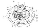
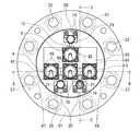
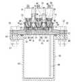
以下に、本発明における処理流体充填容器と、処理流体充填容器一体型ブロックバルブの実施形態を図面に基づいて詳しく説明する。図1においては、本発明における処理流体充填容器と、処理流体充填容器一体型ブロックバルブを示し、図2〜図4においては、その実装基盤を示している。 Embodiments of a processing fluid filling container and a processing fluid filling container integrated block valve according to the present invention will be described below in detail with reference to the drawings. FIG. 1 shows a processing fluid filling container and a processing fluid filling container integrated block valve according to the present invention, and FIGS. 2 to 4 show their mounting bases.
本発明の処理流体充填容器は、例えば、CVD法やMOCVD法により半導体を製造する際において、処理流体を気化又は昇華させて生成した生成流体を外部の図示しない半導体製造装置の反応炉に供給するために用いられる。この場合、生成流体の供給方法としては、例えば、原料を溶解させた処理流体を充填容器に液送しておき、これをキャリアガスによって強制的に気化させて供給する、いわゆる溶液気化法と、充填容器を加熱して充填容器内の処理流体の蒸気圧を高くし、これにキャリアガスをバブリングさせてキャリアガスに処理流体を飽和させた生成流体を供給する、いわゆるバブリング法とがある。以降の実施形態では、溶液気化法を採用した場合の構造の充填容器を述べる。 The processing fluid filling container of the present invention supplies a generated fluid generated by vaporizing or sublimating the processing fluid to a reaction furnace of an external semiconductor manufacturing apparatus (not shown) when a semiconductor is manufactured by, for example, CVD or MOCVD. Used for. In this case, as a supply method of the generated fluid, for example, a processing fluid in which a raw material is dissolved is liquid-fed to a filling container, and this is forcibly vaporized by a carrier gas and supplied, and so-called solution vaporization method, There is a so-called bubbling method in which the filling container is heated to increase the vapor pressure of the processing fluid in the filling container, and the carrier gas is bubbled to supply the generated fluid in which the processing fluid is saturated to the carrier gas. In the following embodiments, a filled container having a structure in which the solution vaporization method is employed will be described.
図1に示すように、処理流体充填容器は、充填容器本体(以下、容器本体という)1を有し、この容器本体1は、実装基盤2と収納体3とを有し、実装基盤2には平面マウント用バルブである集積弁4、5、6が取付けられている。 As shown in FIG. 1, the processing fluid filling container has a filling container main body (hereinafter referred to as a container main body) 1, and the container main body 1 has a mounting
図2、図3において、実装基盤2は、例えば、蓋、天板、鏡板などの容器本体1の上面に位置している上面部位からなり、略円板状に形成されている。この実装基盤2には肉厚部7が設けられ、この肉厚部7内には容器本体1内に連通させた処理流体の供給部8、排出部9、パージ部10が設けられ、これらの供給部8、排出部9、パージ部10の接続シール面11に、集積弁4、5、6が直接平面実装されるようになっている。 2 and 3, the mounting
供給部8、排出部9、パージ部10は、流路ブロック12で構成されており、この流路ブロック12は、継手用連通部13と継手14とを有している。図5に示すように、継手用連通部13は、集積弁4、5、6の供給側又は排出側と連通される連通孔15を有し、継手14は、略L字形状に形成されて図示しない外部流路に接続可能に設けられている。 The
実装基盤2の流路ブロック12の取付け位置には収納溝16が形成されており、この収納溝16に対して流路ブロック12が挿脱自在になっている、このように、流路ブロック12は、実装基盤2に着脱可能に設けられており、流路ブロック12の収納溝16への収納後に、継手用連通部13が実装基盤2上に配設される。 A
実装基盤2における継手用連通部13と対応する位置にはバルブ用連通部17が設けられ、このバルブ用連通部17は、図3における実装基盤2の上面側である外部と、下面側である容器本体1の内部とを連通するように形成されている。更に、排出側集積弁6側のバルブ用連通部17においては、収納体3の内部まで延長するようにチューブ27が設けられている。 A
流路ブロック12を収納溝16に収納した場合には、継手用連通部13とバルブ用連通部17とにより上記した接続シール面11が形成され、この接続シール面11にシール状態で各集積弁4、5、6が取付け可能になっている。接続シール面11の周囲には、後述するフランジ部30取付け用の雌ねじ26が4箇所に形成されている。 When the flow path block 12 is housed in the
実装基盤2の収納溝16の近傍にはメネジ18が形成され、このメネジ18にはオネジ19が螺着可能になっている。L型部材20と固定部材21は、流路ブロック12を収納溝16に収納した状態で固定するために設けられ、L型部材20は、オネジ19が挿通可能な穴部22を有し、固定部材21は、継手14が装着可能な形状の凹溝23と、オネジ19が螺着可能なメネジ24とを有している。また、実装基盤2の外周縁近傍には適宜の間隔で装着穴25が形成されている。 A
図4における各集積弁について、集積弁4は、キャリアガス供給用の供給側集積弁として設けられ、集積弁5は、処理流体にキャリアガスを供給して得られる生成流体を排出するための排出側集積弁として設けられ、一方、集積弁6は、容器本体1内をパージ可能な真空引き用弁として設けられる。
集積弁4、5、6は、実装基盤2に取付け用フランジ部30を介して取付けられ、図5における集積弁4、5、6の底面31と接続シール面11との間にはシール部材32が配設される。For each integrated valve in FIG. 4, the
The
集積弁4、5、6は、一般的な構造を有する自動弁又は手動弁からなり、図5に示すように、その底面31に流入口34と流出口35とからなる流路口33がそれぞれ形成され、流入口34と流出口35との間の流路には弁体36が設けられている。弁体36は、自動又は手動操作により開閉や中間開度の状態に開度調整可能であり、この弁体36の開度調整により、集積弁4によるキャリアガスの供給量と、集積弁5による生成流体の排出量と、集積弁6によるパージ量とがそれぞれ制御可能になっている。 The
図3に示すように、集積弁4、5、6の下部側には略円柱状の取付部40が設けられ、この取付部40の底面31側に前記流入口34と流出口35とが形成されている。更に、取付部40には平行二面部41が適宜の長さで切欠き形成されている。取付部40の外周側には締付ナット42が装着され、この締付ナット42の内周側にはめねじ部43が形成されている。 As shown in FIG. 3, a substantially cylindrical mounting
フランジ部30は、台座部45とこの台座部45から延設した筒状部46とを有している。台座部45には実装基盤2の雌ねじ26の位置に対応した4つの取付孔47が形成され、この取付孔47に雄ねじ48を有するボルト49が挿通可能になっている。筒状部46の上端側には、平行二面部41に対応する突起部50が形成され、この突起部50が平行二面部41に装着可能になっている。筒状部46の外周側には、締付ナット42のめねじ部43と螺着可能なおねじ部51が形成されている。 The
図3に示すように、シール部材32は、例えば、薄型の断面略C字形状に形成され、集積弁4、5、6の流路口33(流入口34、流出口35)と接続シール面11との間に挟着可能な形状に設けられている。 As shown in FIG. 3, the
集積弁4、5、6は、流路口33のうち、何れか一方側の流路口33が継手用連通部13、他方側の流路口33がバルブ用連通部17に連通した状態で実装基盤2にそれぞれ平面実装される。本実施形態においては、供給側の集積弁4における流入口34が継手用連通部13、流出口35がバルブ用連通部17と連通し、排出側集積弁5における流入口34がバルブ用連通部17、流出口35が継手用連通部13と連通し、真空引き用集積弁6における流入口34がバルブ用連通部17、流出口35が継手用連通部13と連通した状態で、各集積弁のフランジ部40が4本のボルト49で固定シールされている。 The
一方、図1に示すように、収納体3は略円筒形状に形成され、その内部に液体や固体状のガス化用材料等の適宜の処理流体が収納される。ガス化用材料としては、例えば、テトラヒドロフラン、トリエトキシボラン、トリエトキシアルシン、トリメチルアルミニウム、トリメチルガリウム、テトラエトキシシラン、四塩化珪素、三塩化砒素などがある。図1、図5において、収納体3の上端側には環状鍔部55が形成され、この環状鍔部55における実装基盤2の装着穴25と対応する位置には貫通穴56が形成されている。 On the other hand, as shown in FIG. 1, the
実装基盤2は、この収納体3に対して、図示しない密封シール用のシール部材、例えば、PFAやPTFE等の樹脂などの耐薬品性を発揮する部材を挟着した状態で、貫通孔56と装着穴25にボルト・ナット57を締め込むことで一体化され、この一体化した実装基盤2と収納体3とにより容器本体1が構成される。 The mounting
続いて、上記の集積弁4、5、6を実装基盤2に平面実装する場合の手順を述べる。この手順では、供給側の集積弁4において、流入口34と継手用連通部13、流出口33とバルブ用連通部17を連通させるように実装する場合を説明する。 Subsequently, a procedure for mounting the
図3において、先ず、実装基盤2の収納溝16に供給部8(流路ブロック12)を収納する。この状態で、凹溝23に継手14を嵌め込みながら固定部材21を装着し、この固定部材21の他方側からL型部材20を継手14に装着して、L型部材20と凹溝23との間に継手14を挟んだ状態にする。そして、オネジ19をメネジ18、24に螺着し、固定部材21とL型部材20、L型部材20と実装基盤2とをそれぞれ固定する。この固定により、流路ブロック12が収納溝16に固定され、継手用連通部13とバルブ用連通部17とにより接続シール面11が実装基盤2の上面側に形成される。 In FIG. 3, first, the supply unit 8 (flow path block 12) is stored in the
次に、台座部45の取付孔47を雌ねじ26の位置に合わせながらフランジ部30を実装基盤2に載置し、4本のボルト49を雌ねじ26に螺着してフランジ部30を実装基盤2に固着する。この状態で接続シール面11と底面31との間にシール部材32を介在させつつ、平行二面部41の向きを突起部50の位置に合わせながら取付部40を筒状部46の内側に取付ける。これにより、流入口34が継手用連通部13、流出口35がバルブ用連通部17とそれぞれ連通した状態で集積弁4が載置される。 Next, the
続いて、めねじ部43とおねじ部51とを螺着させるように締付ナット42を締付けると、図2に示すように集積弁4が実装基盤2に平面実装される。このとき、集積弁4の底面31と接続シール面11との間にシール部材32が挟着され、集積弁4が実装基盤2にシール状態で実装される。 Subsequently, when the tightening
上記と同様の取付け手順により、排出側集積弁5と真空引き用集積弁6とを実装基盤2の所定の位置にそれぞれ平面実装する。この場合、前記したとおり排出側集積弁5、真空引き用集積弁6は、流入口34がバルブ用連通部17、流出口35が継手用連通部13となるように連通させて載置して実装すればよい。 The discharge-side
容器本体1により処理流体から生成流体を設ける場合、実装後の集積弁4、5、6がそれぞれ独立して開閉又は中間開度に制御可能であり、集積弁4、5を制御して容器本体1内部に収納したガス化用材料にキャリアガスを供給して生成流体を得ることが可能になる。例えば、集積弁4を開状態に制御すると、外部流路から容器本体1内にキャリアガスが供給され、このキャリアガスによりガス化用材料が強制的に気化又は昇華される。このときのキャリアガスとしては、例えば、H2、N2、He、Arガスなどがある。続いて、集積弁5を開状態に制御すると、キャリアガスに処理流体が飽和した状態になって生成流体が設けられ、この生成流体は、チューブ27より集積弁5を介して外部の反応炉等に供給される。When the production fluid is provided from the processing fluid by the container body 1, the
また、真空引き用集積弁6を開閉又は中間開度に制御して容器本体1内を真空引きすると、排出側集積弁5、この排出側集積弁5の継手用連通部13、バルブ用連通部17、チューブ27などの領域内に付着する生成流体や不純物が集積弁6を介して外部にパージされる。これにより、生成流体の付着しやすい排出側に生成流体や不純物が付着することを防いで流路を確保でき、集積弁6側からクリーンな生成流体を安定して供給できる。 When the vacuuming
上記実施形態において、説明の便宜上、集積弁を供給側集積弁4、排出側集積弁5、真空引き用集積弁6に分けて説明しているが、これらの集積弁は同一構造であってもよく、同一構造である場合、任意の集積弁を何れかの実装位置に適宜実装することができる。また、図示しないが、容器本体と実装基盤とを一体化したり、接続シール面を実装基盤の上面に一体に構成することも可能である。また、真空引き用の集積弁6と、この真空引き弁を平面実装するための流路ブロック等を省略することもできる。 In the above embodiment, for convenience of explanation, the accumulation valve is divided into the supply
更に、処理流体充填容器は、容器本体の上面部位を実装基盤とし、この実装基盤の供給部と排出部の接続シール面に平面マウント構造により集積弁を直接取付けるようにすれば、その取付け構造にこだわることはなく上記以外の取付け構造により実装基盤に実装してもよい。例えば、図示しないが、集積弁の下端側に矩形状のフランジ部を一体に形成し、このフランジを実装基盤に直接ボルト止めして実装することも可能である。 Furthermore, if the processing fluid filling container has the upper surface portion of the container body as a mounting base, and the integrated valve is directly attached to the connection sealing surface of the supply and discharge parts of the mounting base by a flat mount structure, the mounting structure is improved. You may mount on a mounting board | substrate by attachment structures other than the above without being particular. For example, although not shown, a rectangular flange portion can be integrally formed on the lower end side of the integrated valve, and this flange can be directly bolted to the mounting base for mounting.
また、上記実施形態では、容器本体に集積弁を取付けた処理流体充填容器としているが、実装基盤に集積弁を平面実装してブロックバルブを設け、このブロックバルブを、例えば、内容積の小さい容器本体の上面部位として一体化すれば、上述と同様の構成によって処理流体充填容器一体型ブロックバルブを設けることができる。この処理流体充填容器一体型ブロックバルブは、狭い設置スペースなどに設置することが可能である。 Further, in the above embodiment, the processing fluid filling container is provided with an integrated valve attached to the container body. However, the block valve is provided on the mounting base by mounting the integrated valve on a plane, and the block valve is, for example, a container having a small internal volume. If integrated as an upper surface portion of the main body, the processing fluid filling container integrated block valve can be provided with the same configuration as described above. This processing fluid filling container integrated block valve can be installed in a narrow installation space or the like.
本発明の処理流体充填容器は、上述したように、容器本体1の蓋、天板、鏡板などの上面部位を実装基盤2とし、この実装基盤2の肉厚部7内に容器本体1内に連通させた処理流体の供給部8と排出部9を設け、この供給部8と排出部9の接続シール面11に集積弁4、5を平面マウントにより直接取付けているので、容器本体1と集積弁4、5との間に配管継手等の別の部品を設ける必要がない。この平面実装構造により、容器本体1と集積弁4、5との接合強度を高めることができ、衝撃などが加わった場合でも各部への損傷を防いで処理流体の漏れを確実に防止できる。 In the processing fluid filling container of the present invention, as described above, the upper surface portion of the container body 1 such as the lid, the top plate, and the end plate is used as the mounting
更に、容器本体1と集積弁4、5とによる内部流路の容積が最小限に抑えられるため、パージ時間を低減させて不純物混入のおそれもなくなる。集積弁4、5は、平面実装により実装基盤3に立設した状態で取付けられるため、図5において、弁体39が鉛直方向に移動してシールでき、内部への液溜まり等による流体の残留を防止することができる。 Furthermore, since the volume of the internal flow path by the container main body 1 and the collecting
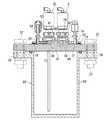
図6ないし図10においては、本発明における処理流体充填容器の他の実施形態を示したものである。なお、この実施形態において、前記実施形態と同一部分は同一符号によって表し、その説明を省略する。
図9、図10に示すように、この実施形態における処理流体充填容器は容器本体60を有し、この容器本体60は、実装基盤61と収納体62とを有している。そして、図6、図8に示すように、容器本体60の上面部である実装基盤62には肉厚部63が一体に突出形成され、この肉厚部63にバイパス用の2つの流路ブロック64、64を収納可能な収納溝65と、真空引き用の流路ブロック12を収納可能な収納溝16とが設けられている。更に、実装基盤62には、供給側集積弁4、排出側集積弁5用のバルブ用連通部72、72とパージ用集積弁6用のバルブ用連通部68が形成され、排出側集積弁5側のバルブ用連通部72においては、収納体62の内部まで延長してチューブ69が設けられている。6 to 10 show another embodiment of the processing fluid filling container according to the present invention. In this embodiment, the same parts as those in the above embodiment are denoted by the same reference numerals, and the description thereof is omitted.
As shown in FIGS. 9 and 10, the processing fluid filling container in this embodiment has a container
図7において、バイパス用の流路ブロック64は、収納溝65に収納可能な形状に形成され、収納溝65に挿脱自在になるように設けられている。このバイパス用流路ブロック64内には、継手用連通部66、66が連通するように形成されている。一方、真空引き用の流路ブロック12には、前述と同様に継手用連通部13が形成されている。 In FIG. 7, the bypass flow path block 64 is formed in a shape that can be stored in the
収納溝65に対して、バイパス用流路ブロック64、64を2つ並べるように収納すると、このバイパス用流路ブロック64、64の隣接する継手用連通部66、66によりバイパス用の集積弁70を平面実装可能な接続シール面71が形成され、かつ、このバイパス用流路ブロック64の他方側の継手用連通部66と実装基盤61のバルブ用連通部72とにより供給側集積弁4、排出側集積弁5を平面実装可能な接続シール面73、73がそれぞれ形成される。
一方、収納溝16に流路ブロック12を収納すると、この流路ブロック12の継手用連通部13と、実装基盤61に形成されたバルブ用連通部68により接続シール面74が形成される。When the bypass channel blocks 64 and 64 are stored in the
On the other hand, when the flow path block 12 is stored in the
接続シール面73、73に供給側集積弁4、排出側集積弁5、接続シール面71にバイパス用集積弁70、接続シール面74に真空引き用集積弁6を載置し、各集積弁のフランジ部30を4本のボルト49により肉厚部63に固定シールすることによりこれらが平面実装される。 The supply
なお、この実施形態においては、肉厚部63を実装基盤62に一体に形成しているが、この肉厚部を実装基盤と別体に設け、実装基盤に図示しない固定用ボルト等の適宜の固着手段により固着するようにしてもよい。この場合、肉厚部に対して各連通部、連通孔、接続シール面等を容易に加工形成することができ、安価に大量生産することも可能になる。 In this embodiment, the
生成流体を設ける場合には、集積弁4、5を開状態、集積弁6、バイパス用集積弁70を閉状態にして、供給側集積弁4からキャリアガスを供給することにより、前記の実施形態と同様に溶液気化法によりガス化用材料から生成流体が得られる。 In the case of providing the product fluid, the
更に、バイパス用集積弁70を開状態にすると、供給側集積弁4と排出側集積弁5との内部流路を、継手用連通部66を介して短絡させることができる。この状態で供給側集積弁4からキャリアガスを供給すると、このキャリアガスは、供給用集積弁4から容器本体60内に供給されると共に、継手用連通部66とバイパス用集積弁70とを介して排出側集積弁5の継手用連通部66から直接排出される。これにより、容器本体60により生成した生成流体にキャリアガスを混入させることが可能になり、流路内の洗浄度を向上させることができる。 Furthermore, when the
また、上述した実施形態と同様に、真空引き用集積弁6により真空引きした場合には、集積弁や継手用連通部、バルブ用連通部、チューブなどの領域内に付着する生成流体や不純物を集積弁6よりパージできる。 Similarly to the above-described embodiment, when evacuation is performed by the evacuation integrated
上記の実施形態では、溶液気化法により生成流体を供給する場合を説明したが、何れの実施形態においてもバブリング法により生成流体を供給することもできる。この場合、供給側集積弁のバルブ用連通部から延長して収納体の内部までチューブを設けた構造とすればよい。 In the above embodiment, the case where the product fluid is supplied by the solution vaporization method has been described. However, in any embodiment, the product fluid can be supplied by the bubbling method. In this case, a tube may be provided extending from the valve communication portion of the supply side integrated valve to the inside of the storage body.
バブリング法において、集積弁4、5を開状態、集積弁6、バイパス用集積弁70を閉状態にしながら供給側集積弁4からキャリアガスを供給すると、キャリアガスがチューブを介してバブリングされる。ガス化用材料は、加熱により気化している状態にあるため、このガス化用材料がキャリアガスに飽和して生成流体が生成される。そして、ガス化用材料は、加熱により蒸気圧が高い状態になっているため、キャリアガスへの飽和状態が確実に維持された状態となり、品質の高い生成流体が排出側集積弁5から排出される。この場合、キャリアガスの供給量や、容器本体内部の温度、内圧、及び、集積弁5からの排出量などを制御することにより、更にパーティクルのより少ない飽和蒸気を生成流体として得ることができる。 In the bubbling method, when carrier gas is supplied from the supply side integrated
何れの場合にも、実装基盤61、集積弁4、5、6、70、フランジ部30に図示しない加熱用のヒーターを設けることができ、この場合、ヒーターを棒状や板状の各種の形状に設け、各部の内側や外側などの適宜の位置に設けることも可能である。 In any case, a heater for heating (not shown) can be provided on the mounting
1、60 容器本体
2 実装基盤
4、5、6 集積弁
7 肉厚部
8 供給部
9 排出部
11 接続シール面
12 流路ブロック
13 継手用連通部
14 継手
15、28 連通孔
16 収納溝
17 バルブ用連通部
30 フランジ部
49 ボルトDESCRIPTION OF
Claims (6)
Translated fromJapanesePriority Applications (1)
| Application Number | Priority Date | Filing Date | Title |
|---|---|---|---|
| JP2009271262AJP5323654B2 (en) | 2009-11-30 | 2009-11-30 | Processing fluid filling container and processing fluid filling container integrated block valve |
Applications Claiming Priority (1)
| Application Number | Priority Date | Filing Date | Title |
|---|---|---|---|
| JP2009271262AJP5323654B2 (en) | 2009-11-30 | 2009-11-30 | Processing fluid filling container and processing fluid filling container integrated block valve |
Publications (2)
| Publication Number | Publication Date |
|---|---|
| JP2011112196A JP2011112196A (en) | 2011-06-09 |
| JP5323654B2true JP5323654B2 (en) | 2013-10-23 |
Family
ID=44234681
Family Applications (1)
| Application Number | Title | Priority Date | Filing Date |
|---|---|---|---|
| JP2009271262AActiveJP5323654B2 (en) | 2009-11-30 | 2009-11-30 | Processing fluid filling container and processing fluid filling container integrated block valve |
Country Status (1)
| Country | Link |
|---|---|
| JP (1) | JP5323654B2 (en) |
Cited By (1)
| Publication number | Priority date | Publication date | Assignee | Title |
|---|---|---|---|---|
| CN110088523A (en)* | 2016-12-14 | 2019-08-02 | 株式会社堀场Stec | Accepting container, material gasification installation and liquid material supply device with the accepting container |
Families Citing this family (1)
| Publication number | Priority date | Publication date | Assignee | Title |
|---|---|---|---|---|
| JP2020070867A (en)* | 2018-10-31 | 2020-05-07 | 株式会社フジキン | Valve block and fluid container |
Family Cites Families (3)
| Publication number | Priority date | Publication date | Assignee | Title |
|---|---|---|---|---|
| JP2007182927A (en)* | 2006-01-06 | 2007-07-19 | Adeka Corp | Fluid vessel with valve |
| JP5073751B2 (en)* | 2006-10-10 | 2012-11-14 | エーエスエム アメリカ インコーポレイテッド | Precursor delivery system |
| JP5000469B2 (en)* | 2007-12-05 | 2012-08-15 | 株式会社キッツエスシーティー | Vessel block valve |
- 2009
- 2009-11-30JPJP2009271262Apatent/JP5323654B2/enactiveActive
Cited By (4)
| Publication number | Priority date | Publication date | Assignee | Title |
|---|---|---|---|---|
| CN110088523A (en)* | 2016-12-14 | 2019-08-02 | 株式会社堀场Stec | Accepting container, material gasification installation and liquid material supply device with the accepting container |
| KR20190094158A (en)* | 2016-12-14 | 2019-08-12 | 가부시키가이샤 호리바 에스텍 | Receiving tank, material vaporizing apparatus provided with the receiving tank, and liquid material supply device |
| US11306913B2 (en) | 2016-12-14 | 2022-04-19 | Horiba Stec, Co., Ltd. | Storage tank, and material vaporization device and liquid material supply device provided with storage tank |
| KR102419170B1 (en)* | 2016-12-14 | 2022-07-08 | 가부시키가이샤 호리바 에스텍 | Accommodating tank, material vaporizing device provided with the receiving tank, and liquid material supplying device |
Also Published As
| Publication number | Publication date |
|---|---|
| JP2011112196A (en) | 2011-06-09 |
Similar Documents
| Publication | Publication Date | Title |
|---|---|---|
| KR100792964B1 (en) | Carburetor in vaporization system | |
| US8322380B2 (en) | Universal fluid flow adaptor | |
| US10443128B2 (en) | Vessel and method for delivery of precursor materials | |
| CN103443903B (en) | The design of multi-stage spray head | |
| US7806143B2 (en) | Flexible manifold for integrated gas system gas panels | |
| JP5000469B2 (en) | Vessel block valve | |
| EP0113518A2 (en) | Bubbler cylinder and dip tube device | |
| JP2006193801A (en) | Vaporizing device and treatment apparatus | |
| KR20040030063A (en) | Integral blocks, chemical delivery systems and methods for delivering an ultrapure chemical | |
| JP5323654B2 (en) | Processing fluid filling container and processing fluid filling container integrated block valve | |
| JP2004063833A (en) | Liquid supply structure | |
| TWI786951B (en) | Filter apparatus with vented core | |
| US20080302426A1 (en) | System and method of securing removable components for distribution of fluids | |
| KR102491004B1 (en) | Block valve and block valve for raw material container | |
| US20240316581A1 (en) | Buffer tank, supply block including buffer tank, and gas supply device | |
| JP2019513894A (en) | Apparatus and method for removing residual precursor inside gas tube after deposition | |
| WO2020122884A1 (en) | Ampoule splash mitigation | |
| CN108538748B (en) | Gas introduction mechanism and heat treatment device | |
| CN222041322U (en) | Solid precursor packaging container | |
| KR200205120Y1 (en) | Block Assembly Gas Supply | |
| WO2019058969A1 (en) | Storage container, aerator, substrate processing device, and method for manufacturing semiconductor device | |
| KR20090005227U (en) | Particle Removal Device |
Legal Events
| Date | Code | Title | Description |
|---|---|---|---|
| A621 | Written request for application examination | Free format text:JAPANESE INTERMEDIATE CODE: A621 Effective date:20120511 | |
| A977 | Report on retrieval | Free format text:JAPANESE INTERMEDIATE CODE: A971007 Effective date:20130614 | |
| TRDD | Decision of grant or rejection written | ||
| A01 | Written decision to grant a patent or to grant a registration (utility model) | Free format text:JAPANESE INTERMEDIATE CODE: A01 Effective date:20130702 | |
| A61 | First payment of annual fees (during grant procedure) | Free format text:JAPANESE INTERMEDIATE CODE: A61 Effective date:20130717 | |
| R150 | Certificate of patent or registration of utility model | Ref document number:5323654 Country of ref document:JP Free format text:JAPANESE INTERMEDIATE CODE: R150 Free format text:JAPANESE INTERMEDIATE CODE: R150 | |
| R250 | Receipt of annual fees | Free format text:JAPANESE INTERMEDIATE CODE: R250 | |
| R250 | Receipt of annual fees | Free format text:JAPANESE INTERMEDIATE CODE: R250 | |
| R250 | Receipt of annual fees | Free format text:JAPANESE INTERMEDIATE CODE: R250 | |
| R250 | Receipt of annual fees | Free format text:JAPANESE INTERMEDIATE CODE: R250 | |
| R250 | Receipt of annual fees | Free format text:JAPANESE INTERMEDIATE CODE: R250 | |
| R250 | Receipt of annual fees | Free format text:JAPANESE INTERMEDIATE CODE: R250 | |
| R250 | Receipt of annual fees | Free format text:JAPANESE INTERMEDIATE CODE: R250 | |
| R250 | Receipt of annual fees | Free format text:JAPANESE INTERMEDIATE CODE: R250 | |
| R250 | Receipt of annual fees | Free format text:JAPANESE INTERMEDIATE CODE: R250 | |
| R250 | Receipt of annual fees | Free format text:JAPANESE INTERMEDIATE CODE: R250 |