JP5323512B2 - Input device - Google Patents
Input deviceDownload PDFInfo
- Publication number
- JP5323512B2 JP5323512B2JP2009016907AJP2009016907AJP5323512B2JP 5323512 B2JP5323512 B2JP 5323512B2JP 2009016907 AJP2009016907 AJP 2009016907AJP 2009016907 AJP2009016907 AJP 2009016907AJP 5323512 B2JP5323512 B2JP 5323512B2
- Authority
- JP
- Japan
- Prior art keywords
- input
- display unit
- touch panel
- fiber material
- fiber
- Prior art date
- Legal status (The legal status is an assumption and is not a legal conclusion. Google has not performed a legal analysis and makes no representation as to the accuracy of the status listed.)
- Expired - Fee Related
Links
Images


Landscapes
- Input From Keyboards Or The Like (AREA)
- Position Input By Displaying (AREA)
- User Interface Of Digital Computer (AREA)
Description
Translated fromJapanese本発明は、タッチパネルを利用している電子機器の入力装置に関する。 The present invention relates to an input device for an electronic device using a touch panel.
前記タッチパネルを利用している電子機器とは、具体的には、携帯電話機のタッチパネル、パーソナルコンピュータ(以下、「パソコン」という。)のタッチパネル、ノート型パソコンのタッチパネル、PDA(Personal Digital Assistant)のタッチパネル、ゲーム機のタッチパネル、カメラ機のタッチパネル、テレビジョン(以下、「テレビ」という。)のタッチパネル、各種測定器のタッチパネル、公共施設等に設置されている案内用の機器のタッチパネル、等をいう。 Specifically, the electronic devices using the touch panel include a touch panel of a mobile phone, a touch panel of a personal computer (hereinafter referred to as “PC”), a touch panel of a notebook computer, and a touch panel of a PDA (Personal Digital Assistant). A touch panel of a game machine, a touch panel of a camera machine, a touch panel of a television (hereinafter referred to as “TV”), a touch panel of various measuring instruments, a touch panel of guidance equipment installed in a public facility, and the like.
特許文献1には、タッチパネルボタンの境界を作るためにボタン部に穴が空いたカバーを重ねることで視覚障害者も容易にタッチパネル操作ができる技術が記載されている。 Japanese Patent Application Laid-Open No. 2004-151561 describes a technology that enables a visually impaired person to easily operate a touch panel by overlaying a cover with a hole in a button portion in order to create a boundary of a touch panel button.
しかしながら、特許文献1の技術では、タッチパネルの境界を形成する手段はボタン部に穴が空いたカバーであるため、あらかじめ決められたパターンでしかボタンの境界を形成することができないという欠点があった。
また、特許文献1の発明ではボタンの配置や数が変わった時に、シートを取り換えなければタッチパネルの境界を変化させることができないという欠点があった。However, in the technique of
Further, the invention of
本発明の目的は、タッチパネルの境界を動的に変化させることができる入力装置を提供することである。 An object of the present invention is to provide an input device capable of dynamically changing the boundary of a touch panel.
本発明の第1の観点の入力装置は、複数の入力キー配置を切替表示する表示部と、前記表示部に重畳して配置されるタッチパネルと、通電状態に応じて緊張収縮、弛緩伸張する繊維材料と、前記表示部に現在表示されている入力キーの境界部分の前記繊維材料が緊張収縮するよう、前記繊維材料への前記通電状態を制御する制御部と、を有し、前記制御部は、通電する前記繊維材料の数を、前記表示部に現在表示されている個別の入力キーの面積に応じて変化させる。An input device according to a first aspect of the present invention includes a display unit that switches and displays a plurality of input key arrangements, a touch panel that is superimposed on the display unit, anda fiber that contracts and relaxes and relaxes depending on theenergized state. andmaterials,so that the fiber material at the boundary of the input keys being displayed currently on the display unitis tense contraction, and a control unitfor controlling the energization state to the fibrous material, wherein the control unitThe number of the fiber materials to be energized is changed according to the area of the individual input keys currently displayed on the display unit .
本発明の第2の観点の入力装置は、複数の入力キー配置を切替表示する表示部と、前記表示部に重畳して配置されるタッチパネルと、通電状態に応じて緊張収縮、弛緩伸張する繊維材料と、前記表示部に現在表示されている入力キーの境界部分の前記繊維材料が緊張収縮するよう、前記繊維材料への前記通電状態を制御する制御部と、を有し、前記制御部は、複数の入力キーが同時に押圧されている場合には、当該複数の押圧されている入力キー内部に配置されている前記繊維材料に通電する。An input device according to a second aspect of the present invention includes a display unit that switches and displays a plurality of input key arrangements, a touch panel that is arranged so as to overlap the display unit, and a fiber that contracts and relaxes and relaxes depending on the energized state. and materials, so that the fiber material at the boundary of the input keys being displayed currently on the display unit is tensioned contracts,have a, a control unit for controlling the energization state to the fibrousmaterial, wherein the control unit When a plurality of input keys are pressed at the same time, the fiber material disposed inside the plurality of pressed input keys is energized .
本発明の第3の観点の入力装置は、複数の入力キー配置を切替表示する表示部と、前記表示部に重畳して配置されるタッチパネルと、通電状態に応じて緊張収縮、弛緩伸張する繊維材料と、前記表示部に現在表示されている入力キーの境界部分の前記繊維材料が緊張収縮するよう、前記繊維材料への前記通電状態を制御する制御部と、を有し、前記制御部は、所定の機能の発現に必要な入力キー以外が押圧されている場合には、少なくとも当該押圧されている入力キー内部に配置されている前記繊維材料に通電する。An input device according to a third aspect of the present invention includes a display unit that switches and displays a plurality of input key arrangements, a touch panel that is arranged so as to be superimposed on the display unit, and a fiber that is tension-contracted and relaxed / relaxed according to an energized state A control unit that controls the energization state of the fiber material so that the fiber material at the boundary portion of the input key currently displayed on the display unit contracts and contracts. When akey other than the input key necessary for the expression of apredetermined function is pressed, at least the fiber material disposed inside the pressed input key is energized .
本発明の第4の観点の入力装置は、複数の入力キー配置を切替表示する表示部と、前記表示部に重畳して配置されるタッチパネルと、前記複数の入力キー配置において表示される入力キーの境界線に沿って、前記タッチパネルと前記表示部との間に配置され、通電状態に応じて緊張収縮、弛緩伸張する繊維材料と、前記表示部に現在表示されている入力キーの境界線に沿う前記繊維材料が緊張収縮するよう、前記繊維材料への前記通電状態を制御する制御部と、を有し、前記制御部は、通電する前記繊維材料の数を、前記表示部に現在表示されている個別の入力キーの面積に応じて変化させる。An input device according to a fourth aspect of the present invention includes a display unit that switches and displays a plurality of input key arrangements, a touch panel that is superimposed on the display unit, and input keys that are displayed in the plurality of input key arrangements. A fiber material that is disposed between the touch panel and the display unit along the boundary line, and that contracts and relaxes depending on the energized state, and the boundary line of the input key currently displayed on the display unit. A control unit that controls the energization state of the fiber material so that the fiber material along the line contracts and contracts, and the control unitcurrently displays the number of the fiber materials to be energized on the display unit. It changes according to the area of the individual input keys .
本発明の第5の観点の入力装置は、複数の入力キー配置を切替表示可能な表示部と、前記表示部に重畳して配置されるタッチパネルと、前記タッチパネルの被操作面側に配置され、通電状態に応じて緊張収縮、弛緩伸張する繊維材料と、前記繊維材料が緊張収縮するよう、前記繊維材料への前記通電状態を制御する制御部と、を有し、前記制御部は、前記表示部に現在表示されている入力キーの境界線に沿っている前記繊維材料が緊張収縮するように前記通電状態を制御し、前記制御部は、通電する前記繊維材料の数を、前記表示部に現在表示されている個別の入力キーの面積に応じて変化させる。An input device according to afifth aspect of the present invention is arranged on a display unit capable of switching and displaying a plurality of input key arrangements, a touch panel arranged so as to overlap the display unit, andan operated surface side of the touch panel , a tension contract in response to the conduction state, and fibrous materials to relaxstretching, sothat the pre-Symbol fiber material tensioned contracted, and a control unit for controlling the energization state to the fibrous material,wherein, prior to The energization state is controlled so that the fiber material along the boundary line of the input key currently displayed on the display unit is contracted and contracted, and the control unit displays the number of the fiber materials to be energized. The area is changed according to the area of the individual input key currently displayed in the section.
本発明の第6の観点の入力装置は、複数の入力キー配置を切替表示可能な表示部と、前記表示部に重畳して配置されるタッチパネルと、前記タッチパネルの被操作面側に配置され、通電状態に応じて緊張収縮、弛緩伸張する繊維材料と、前記繊維材料が緊張収縮するよう、前記繊維材料への前記通電状態を制御する制御部と、を有し、前記制御部は、複数の入力キーが同時に押圧されている場合には、当該複数の押圧されている入力キー内部に配置されている前記繊維材料に通電する。An input device according to asixth aspect of the present invention is arranged on a display unit capable of switching and displaying a plurality of input key arrangements, a touch panel arranged so as to overlap the display unit, and an operated surface side of the touch panel, A fiber material that tensions and contracts and relaxes and stretches in accordance with an energized state; and a control unit that controls the energized state of the fiber material so that the fiber material is tensioned and contracted. When the input keys are pressed at the same time, the fiber material disposed inside the plurality of pressed input keys is energized.
本発明の第7の観点の入力装置は、複数の入力キー配置を切替表示可能な表示部と、前記表示部に重畳して配置されるタッチパネルと、前記タッチパネルの被操作面側に配置され、通電状態に応じて緊張収縮、弛緩伸張する繊維材料と、前記繊維材料が緊張収縮するよう、前記繊維材料への前記通電状態を制御する制御部と、を有し、前記制御部は、所定の機能の発現に必要な入力キー以外が押圧されている場合には、少なくとも当該押圧されている入力キー内部に配置されている前記繊維材料に通電する。
An input device according to aseventh aspect of the present invention is arranged on a display unit capable of switching and displaying a plurality of input key arrangements, a touch panel arranged so as to overlap the display unit, and an operated surface side of the touch panel, A fiber material that tensions and contracts and relaxes and stretches in accordance with an energized state; and a control unit that controls the energized state of the fiber material so that the fiber material is tensioned and contracted. When a key other than the input key necessary for function expression is pressed, at least the fiber material disposed inside the pressed input key is energized.
本発明によると、タッチパネルの境界を動的に変化させることができる入力装置を提供することができる。 ADVANTAGE OF THE INVENTION According to this invention, the input device which can change the boundary of a touch panel dynamically can be provided.
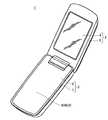
図1は、本発明の実施形態に係る携帯電話機1の外観を開状態で示す斜視図である。 FIG. 1 is a perspective view showing an external appearance of a
携帯電話機1は、いわゆる折り畳み式の携帯電話機1として構成されており、開状態と閉状態との間で互いに回動可能に連結された第1筐体2及び第2筐体3を有している。図1は、第1筐体2及び第2筐体3の開状態を示している。第1筐体2は、第2筐体3と対向する部分を構成する第1筐体フロントケース4と、第2筐体3とは反対側部分を構成する第1筐体リアケース5とを有している。第2筐体3は、第1筐体2と対向する部分を構成する第2筐体フロントケース6と、第1筐体2とは反対側部分を構成する第2筐体リアケース7とを有している。 The
第1筐体フロントケース4及び第1筐体リアケース5はネジ等により互いに固定され、第1筐体フロントケース4及び第1筐体リアケース5の間に形成された空間に種々の電子部材を収容する収容空間を構成する。第2筐体フロントケース6及び第2筐体リアケース7もネジ等により互いに固定され、第2筐体フロントケース6及び第2筐体リアケース7の間に形成された空間に種々の電子部材を収容する収容空間を構成する。
これらの第1筐体フロントケース4、第1筐体リアケース5、第2筐体フロントケース6及び第2筐体リアケース7は、例えば、樹脂により形成されている。The first
The first casing
第2筐体フロントケース6にはタッチパネル式ディスプレイ8が配設されている。
タッチパネル式ディスプレイ8は、LCD(Liquid Crystal Display(液晶ディスプレイ))やOLED(Organic light-emitting diode(有機EL))等の表示部48を有する。
そして、後述する制御部46が表示部48の表示内容を制御している。
さらに、タッチパネル式ディスプレイ8は表示部48に加えてタッチパネル9をも有する。タッチパネル9はユーザの押圧用の器具又は指によって押圧されていることを検出して制御部46へその旨の信号を発信する。
このタッチパネル式ディスプレイ8の構造及び機能については後で詳述する。A
The
A
Further, the
The structure and function of the
なお、方向を示すときは、第1筐体リアケース5から第1筐体フロントケース4に向かう方向を内部側方向IPRCといい、第1筐体フロントケース4から第1筐体リアケース5に向かう方向を外部側方向OPRCという。
同様に第2筐体リアケース7から第2筐体フロントケース6に向かう方向を内部側方向IPRCといい、第2筐体フロントケース6から第2筐体リアケース7に向かう方向を外部側方向OPRCという。When the direction is indicated, the direction from the first housing
Similarly, the direction from the second casing
図2は図1の携帯電話機1の信号処理系を示すブロック図である。 FIG. 2 is a block diagram showing a signal processing system of the
図2に示されるように、携帯電話機1は、制御・処理の中枢である制御部46、操作部47、表示部48、通信部49、記憶部50及び表面形状形成部51のそれぞれが、アドレス、データ、コントロールのためのラインが複数本からなるシステムバス52に共通に接続され、構成される。 As shown in FIG. 2, the
操作部47は、ユーザが行うタッチパネル9及びその他の入力キーへの入力を検出し、その情報を制御部46に出力する。 The
表示部48は、LCDやOLEDを用いて構成されており、制御部46から供給される映像信号に応じた画像を表示する。
表示部48は、例えば、通信部49による無線発信時における発信先の電話番号、着信時における発信元の電話番号、受信メールや送信メールの内容、日付、時刻、電池残量、発信成否、待ち受け画面等を表示する。
さらに、表示部48はタッチパネル9と連動して入力キーを表示する。この場合には、表示部48は入力キーを表示し、その表示された入力キーに対応する部分への押圧をタッチパネル9が検出したときに、表示部48が表示していた入力キーの入力とする。
なお、LCD及びOLEDは単なる例示であり、表示内容を変えることができるディスプレイであればどのようなものであってもよい、たとえば、CRT(Cathode Ray Tube(ブラウン管テレビジョン))であってもよい。The
The
Further, the
Note that the LCD and OLED are merely examples, and any display that can change the display content may be used, for example, a CRT (Cathode Ray Tube (CRT)). .
通信部49は、通信ネットワークに接続される基地局との間で無線通信を行い、各種データの送受信を行う。 The
記憶部50では、携帯電話機1の各種処理に利用される各種データを記憶する。記憶部50は、例えば制御部46が実行するコンピュータのプログラム、通信相手の電話番号や電子メールアドレス等の個人情報を管理するアドレス帳、各種の設定データ、プログラムの処理過程で利用される一時的なデータが記憶される。 The
表面形状形成部51は、後述するバイオメタルファイバー28とバイオメタルファイバー28への通電を行う駆動回路から形成されている。
そして、駆動回路は、バイオメタルファイバー28への電圧を印加及び停止を行って、バイオメタルファイバー28への通電をON及びOFFしている。
そして、駆動回路は、バイオメタルファイバー28への通電をON及びOFFすることによって、タッチパネル式ディスプレイ8の表面形状を変化させている。
また、表面形状形成部51は、タッチパネル式ディスプレイ8の表面形状を変化させることにとどまらず、タッチパネル9をユーザが押圧することができないようにする機能も有している。The surface
The drive circuit applies and stops the voltage to the
The drive circuit changes the surface shape of the
In addition, the surface
制御部46は、携帯電話機1の全体的な動作を統括的に制御する。
すなわち、制御部46は、携帯電話機1の各種処理(回線交換網を介して行われる音声通話、電子メールの作成と送受信等)が操作部47の操作に応じて適切な手順で実行されるように、上述した各ブロックの動作(通信部49における信号の送受信、表示部48における画像の表示、撮像部15における撮像処理等)を制御する。
さらに、制御部46は、記憶部50に格納されるプログラム(オペレーティングシステム、アプリケーションプログラム等)に基づいて処理を実行するコンピュータ(マイクロプロセッサ)を備えており、このプログラムにおいて指示された手順に従って上述した処理を実行する。
すなわち、制御部46は、記憶部50に格納されるオペレーティングシステムやアプリケーションプログラム等のプログラムから命令コードを順次受け取って処理を実行する。The
That is, the
Furthermore, the
That is, the
表示部48と操作部47との関係において、制御部46は表示部48に表示する入力キーを決定する。具体的には、どの入力キーを表示させるか、表示させる場合にはその入力キーの大きさを決定する。
また、制御部46は、表示している入力キーに対応する部分の押圧があったことをタッチパネル9が検出した場合に表示している入力キーの入力があったものと判断する。
さらに、制御部46は複数の入力キーの境界部分を突起させるように、表面形状形成部51に指示を発行する機能を有している。これによって、ユーザは視覚的のみならず、触覚的にも入力キーの形状を認識することができ、入力間違いを防ぐことができる。In the relationship between the
Further, the
Further, the
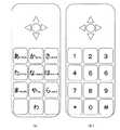
図3〜図5はタッチパネル式ディスプレイ8の表示部48が表示する内容の一例である。 3 to 5 are examples of contents displayed on the
図3の(a)及び(b)のように、通常のボタン式の携帯電話機1が有するボタンと同様の内容、つまり「あいうえお入力」及び「テンキー入力」、を表示することも可能である。
また、図4のように、単純に「はい(Yes)」と「いいえ(No)」を表示することも可能である。
さらに、図5のように、パソコンのキーボードと同様の内容を表示(以下、「フルキーボード表示」という。)することも可能である。As shown in FIGS. 3A and 3B, it is possible to display the same contents as the buttons of the normal button-type
Further, as shown in FIG. 4, “Yes” and “No” can be simply displayed.
Furthermore, as shown in FIG. 5, it is possible to display the same content as a keyboard of a personal computer (hereinafter referred to as “full keyboard display”).
表示部48に表示される内容は、上記図3〜図5に記載された内容にとどまるものではなく、様々な内容を表示可能である。そして、表示部48に表示される内容に応じてタッチパネル9によって検出するキー入力の内容も変化する。 The contents displayed on the
図6(a)(b)は一般的なタッチパネル式ディスプレイ8の構成・機能を説明するための説明図である。 FIGS. 6A and 6B are explanatory diagrams for explaining the configuration and functions of a general
図6に記載されているように、タッチパネル式ディスプレイ8はタッチパネル9と表示部48から構成され、表面側にタッチパネル9を配置することが一般的である。
タッチパネル9は、内部側フィルム16、内部側導電膜14、表面側導電膜12及び表面側フィルム10の順に内部側から配置されている。
表面側導電膜12と内部側導電膜14の間は一定の間隔が空けられている。当該間隔にはドットスペーサ18が配置される。
表面側フィルム10及び内部側フィルム16は、例えば、PET樹脂(Polyethylene Terephthalate)によって構成される。As shown in FIG. 6, the
The
A constant gap is provided between the surface-side
The
表示部48は、表面側パネル20、液晶部材22及び内部側パネル24によって構成されている。そして、内部側パネル24、液晶部材22及び表面側パネル20の順に内部側から配置されている。
なお、図示していないが、タッチパネル9の表面側フィルム10のさらに表面側にはハードコートが配置される。このハードコートは表面側フィルム10がユーザの爪などによって傷つくことを防ぐためのものである。この目的を達成するために、ハードコートは硬度の高い材料から構成される。The
Although not shown, a hard coat is disposed on the surface side of the
図6(b)はユーザによる押圧がなされたことを検出する手段について説明する説明図である。 FIG. 6B is an explanatory diagram for explaining a means for detecting that the user has pressed.
図6(b)のように、ユーザによって押圧があった場合には、押圧力によって表面側フィルム10及び表面側導電膜12が撓む。表面側導電膜12が撓んで内部側導電膜14と接触すると電流が流れ、これを検出することによって押圧があることを検出している。 As shown in FIG. 6B, when the user presses, the
図7は、本発明に係るタッチパネル式ディスプレイ8の説明図である。 FIG. 7 is an explanatory diagram of the
本発明では、このようなタッチパネル式ディスプレイ8に、バイオメタルファイバー28が配置されている。より具体的には、タッチパネル9の表面側にバイオメタルファイバー28が埋め込まれたバイオメタルファイバー含有フィルム27が配置される。
なお、バイオメタルファイバー28の直径は0.05mm程度であり、液晶の1つのドットの大きさは0.15mm程度であるから、表示部48の表面側にバイオメタルファイバー28を配置しても、ドットがつぶれるということはない。In the present invention, the
In addition, since the diameter of the
図8は、バイオメタルファイバー含有フィルム27にバイオメタルファイバー28が埋め込まれる様子を説明するための説明図である。このように、バイオメタルファイバー28は一定間隔をあけて、格子状に配置される。
なお、バイオメタルファイバー28の配置は必ずしも図8のように縦横にかつ一定間隔である必要はなく、用途及び目的に応じて適宜選択可能である。具体的には、縦のみの配置であってもよいし、バイオメタルファイバー28の機能を必要とする部分に対して集中的に配置することもできる。FIG. 8 is an explanatory diagram for explaining a state in which the
The arrangement of the
図9はバイオメタルファイバー28の機能を説明するための説明図である。 FIG. 9 is an explanatory diagram for explaining the function of the
バイオメタルファイバー28は、電流が流れていない場合には柔らかく容易に撓むことが可能であるが、電流が流れると強い力で収縮しかつピアノ線のように強靭となる緊張収縮する材質である。
したがって、バイオメタルファイバー28は、電流が流れている時には緊張収縮するが、電流が流れなくなると弛緩伸張する。
図9(a)では電源34(例えば、電池)及びスイッチ32がバイオメタルファイバー28に接続されているが、スイッチ32はOFF状態であるため、バイオメタルファイバー28は軟状態であり、撓んでいる。
一方、図9(b)ではスイッチ32はON状態であるため、バイオメタルファイバー28に電圧が加えられ、これによって電流が流れる。
そして、電流がながれると、バイオメタルファイバー28は収縮しかつ緊張し剛性が強くなるので、容易に撓まない。
以下、電圧が印加されていないバイオメタルファイバー28を表す時には破線でかつ細い線で記載する。一方、電圧が印加されているバイオメタルファイバー28を表す時には実線でかつ太線で表す。
さらに、電圧が印加され電流が流れているバイオメタルファイバー28と、電圧が印加されておらず電流が流れていないバイオメタルファイバー28とを区別するために、電圧が印加され電流が流れているバイオメタルファイバー28を「通電バイオメタルファイバー29」と、品名及び符号番号を変更する。The
Therefore, the
In FIG. 9A, the power source 34 (for example, battery) and the
On the other hand, in FIG. 9B, since the
When the current is applied, the
Hereinafter, when the
Furthermore, in order to distinguish between the
図10は、一本に電圧が印加されている通電バイオメタルファイバー29の機能を説明するための説明図である。 FIG. 10 is an explanatory diagram for explaining the function of the energized
通電バイオメタルファイバー29の部分は、電圧が印加されていることによってバイオメタルファイバー28が収縮しかつ緊張し剛性が強くなっているのであるから、ユーザがその部分を押圧しようとしても通常の力では不可能である。
そして、押圧ができなければ、タッチパネル9も入力キーの押圧を検出し得ない。
一方、電圧が印加されていないバイオメタルファイバー28部分は軟らかく、かつ、収縮もしてもいないことから、ユーザは容易に押圧可能である。The portion of the energized
If the
On the other hand, since the
図11は、バイオメタルファイバー28に通電している場合のタッチパネル式ディスプレイ8の表面の変化を説明する説明図である。 FIG. 11 is an explanatory diagram for explaining a change in the surface of the
図11(a)では、バイオメタルファイバー28には通電されていないので、バイオメタルファイバー28は弛緩伸張している。
それゆえ、固定部材36にバイオメタルファイバー28の両端が固定されていても、図11(a)のように、U字型に撓みを生じている。In FIG. 11A, since the
Therefore, even if both ends of the
図11(b)は、図11(a)のバイオメタルファイバー28のうち一本に電圧を印加した場合のタッチパネル式ディスプレイ8の表面の変化を表すものである。
電圧を印加するとバイオメタルファイバー28は緊張収縮することから、通電バイオメタルファイバー29は、その中央付近が持ち上がり、通電バイオメタルファイバー29が固定部材36と結合している結合部分間をまっすぐにつなぐ棒のように変化する。
通電バイオメタルファイバー29が持ち上がるのに伴い、バイオメタルファイバー含有フィルム27の通電バイオメタルファイバー29の周り部分も同時に持ち上がる。FIG. 11B illustrates a change in the surface of the
When a voltage is applied, the
As the energized
図12は図11のXII−XII断面であり、バイオメタルファイバー28の1本に電圧を印加したときにタッチパネル式ディスプレイ8の表面がどのように変化するのかを説明するための説明図である。 FIG. 12 is a cross-sectional view taken along the line XII-XII in FIG. 11, and is an explanatory diagram for explaining how the surface of the
前述のように、通電している通電バイオメタルファイバー29の周り部のバイオメタルファイバー含有フィルム27は、通電バイオメタルファイバー29の中央付近が持ち上がり棒のようになるのに伴い持ち上げられる。
一方、電圧が印加されていないバイオメタルファイバー28の周りのバイオメタルファイバー含有フィルム27は持ち上がらないのであるから、図12のような断面形状を有することになる。
このように、盛り上がった部分を突起部分38といい、他の盛り上がっていない部分を平坦部分40ということとする。
なお、現実には図12に記載したほど極端に持ち上がらないが、説明のために強調して記載している。As described above, the biometal fiber-containing
On the other hand, the biometal fiber-containing
In this way, the raised portion is referred to as a protruding
In reality, it does not rise as much as shown in FIG. 12, but it is emphasized for explanation.
図13は、入力キーの境界を突起部分38によって形成する方法を説明する説明図である。 FIG. 13 is an explanatory diagram for explaining a method of forming the boundary of the input key by the protruding
制御部46は、表示部48に現在表示されている入力キーの境界部分に配置されているバイオメタルファイバー28に電圧を印加し電流を流す。
そうすると、入力キーの境界部分が通電バイオメタルファイバー29によって盛り上がり、突起部分38を形成する。
これによって、タッチパネル式ディスプレイ8に表示される入力キーの境界に突起部分38を形成することができる。The
As a result, the boundary portion of the input key is raised by the energized
As a result, the protruding
なお、図13において、突起部分38は直方体状の形状を有するように記載しているが、図面を分かりやすく表現するためであり、実際上はなだらかに突起部分38が形成される。 In FIG. 13, the protruding
[変形例その1]
以上の実施の態様では、単に表示部48に表示されている入力キーの境界に突起部分38を形成して入力キーの境界を触覚的に認識できるようにしただけであるが、さらに有利な実施の態様について以下記載する。[Modification 1]
In the embodiment described above, the protruding
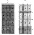
図14は、本発明の変形例その1を説明するための説明図である。 FIG. 14 is an explanatory diagram for explaining a first modification of the present invention.
図14(a)は、表示部48に表示されている入力キーの数が少ない場合の通電バイオメタルファイバー29の例である。図14(b)は、表示部48に表示されている入力キーの数が多い場合の通電バイオメタルファイバー29の例である。 FIG. 14A shows an example of the energized
このように、入力キーの面積を十分に取ることができる場合には、境界線をよりはっきり触覚的に認識できるようにするために、複数本(具体的には3本)のバイオメタルファイバー28に選択的に電圧を印加して通電バイオメタルファイバー29とすることも可能である。
一方、図14(b)のようにフルキーボードの表示を行っている時には、入力キーの数が多く、入力キーの面積を十分に取ることができない。その場合には入力キーの境界を形成する通電バイオメタルファイバー29の本数は最少の本数(具体的には1本)とすることもできる。In this way, when the area of the input key can be sufficiently taken, a plurality of (specifically, three)
On the other hand, when a full keyboard is displayed as shown in FIG. 14B, the number of input keys is large, and the area of the input keys cannot be taken sufficiently. In that case, the number of energized
このように、入力キーの面積に応じて通電バイオメタルファイバー29を順次変化させることが望ましい。
したがって、図14(a)と図14(b)の中間の入力キーの面積であれば、通電バイオメタルファイバー29の本数を、図14(a)と図14(b)との中間の本数(具体的には2本)とすることが望ましい。
さらに、図14(a)よりも入力キーの面積が大きい場合(例えば図4の場合)には、より通電バイオメタルファイバー29の本数をより多く(例えば5本)することができる。In this way, it is desirable to sequentially change the energized
Therefore, if the area of the input key is intermediate between FIGS. 14A and 14B, the number of energized
Furthermore, when the area of the input key is larger than that in FIG. 14A (for example, in the case of FIG. 4), the number of energized
[変形例その2]
他の有利な変形例について記載する。
バイオメタルファイバー28に電圧を印加し電流を流すと、そのバイオメタルファイバー28は通電バイオメタルファイバー29となり、通電バイオメタルファイバー29が存在する部分には突起部分38が生じる。
この突起部分38を入力キーの境界としてのみ用いるのが、前述までの実施形態及び変形例その1であった。
しかし、入力キーが表示されている部分についてもバイオメタルファイバー28は配置されている。
そして、入力キーが表示されている部分をユーザが押圧した時に、その入力キーが表示されている部分に突起部分38を発生させれば、ユーザは急に突起部分38が生ずるのであるから触覚的に入力キー部分が押し返してきたことを感じることができる。
この、押し返すという機能を一種の出力装置とすることが考えられる。
以下、具体的な例について述べる。[Modification 2]
Other advantageous variants are described.
When a voltage is applied to the
The above-described embodiment and
However, the
Then, when the user presses the portion where the input key is displayed, if the
This function of pushing back can be considered as a kind of output device.
Specific examples will be described below.
図15は、本発明の変形例その2における実施の態様を説明するための説明図である。 FIG. 15 is an explanatory diagram for explaining an embodiment of the second modification of the present invention.
前述のように表示されている入力キーの境界部分に突起部分38を発生させても、その突起量はわずかであるから複数の入力キーを同時に押してしまうことがありうる。その場合には入力は無効とされるが、ユーザは複数の入力キーを同時に押したことによって入力が無効となってしまっていることについて認識していないということがありえる。
そこで、たとえば、図15において入力キー「4」と「7」とをユーザが同時に押している時には、入力キー「4」と「7」部分に含まれるバイオメタルファイバー28に電圧を印加して通電バイオメタルファイバー29として、突起部分38を入力キー「4」及び「7」に発生させる。
このように、突起部分38が発生すると、ユーザは押し返される様に感じるはずであり、これによって複数の入力キーを跨って押していることを認識することができる。Even if the protruding
Therefore, for example, when the user simultaneously presses the input keys “4” and “7” in FIG. 15, a voltage is applied to the
As described above, when the protruding
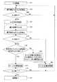
図16は押し返しを行う場合の制御方法の一例を表したフローチャートである。 FIG. 16 is a flowchart showing an example of a control method when pushing back.
<ステップ101>
ステップ101では、入力開始処理がなされる。<Step 101>
In
<ステップ103>
ステップ103では、タッチパネル9を含む操作部47になされるユーザによる入力を検出する。<Step 103>
In
<ステップ105>
ステップ105では、ステップ103の入力の有無を判定して、入力がない時には再度ステップ103に戻って入力を待つという処理がなされる。<Step 105>
In
<ステップ107>
ステップ107では、ステップ103で入力された入力内容を保存する。<Step 107>
In
<ステップ109>
ステップ109では、微小時間処理を停止する。<Step 109>
In
<ステップ111>
ステップ111では、再度、タッチパネル9を含む操作部47になされるユーザによる入力を検出する。<Step 111>
In
<ステップ113>
ステップ113では、ステップ111で入力があったのかを判定している。そして、ステップ111で入力がない場合には、ステップ103での入力をも無効にする後述するステップ125の処理に移行する。
ステップ111でも入力があった場合にはステップ115の処理に移行する。
なぜ、ステップ103での入力に加えてステップ111での入力もなければ入力として認めず、ステップ103での入力をも無効とする必要があるのか説明する。
タッチパネル9による入力の場合、タッチパネル式ディスプレイ8をユーザが軽く触れただけで入力として認識されてしまう。この点は、ある程度確実に押し込まなければ入力とならないボタン式の操作部47とは異なる点である。
この様に軽く触れただけで入力として認識してしまうと、その入力キーをタッチする意思がないにもかかわらず、誤って触れてしまい、それをタッチパネル9が入力として検出することがありうる。
このような場合を排除するために、微小時間後にも入力があるかを判定し、入力がある場合に限ってタッチパネル9による操作があったものとするステップ113の処理の必要があるからである。<Step 113>
In
If there is also an input in
The reason why it is necessary to invalidate the input in
In the case of input by the
If it is recognized as an input simply by lightly touching in this way, it may be touched by mistake even though there is no intention to touch the input key, and the
In order to eliminate such a case, it is necessary to determine whether or not there is an input even after a minute time, and it is necessary to perform the process of
<ステップ115>
ステップ115において、ステップ107で保存されているステップ103で入力された内容とステップ111で入力された内容とを比較して同一の入力であったかを判定している。
そして、同一の入力ではない場合には、ステップ123の処理に移行する。同一の場合には、入力を有効とするステップ117の処理に移行する。
なぜ、ステップ103での入力内容と、ステップ111での入力内容が同一であるかを判定して同一の場合のみ入力を有効とするのか説明する。
タッチパネル9による入力の場合、突起部分38があっても、その突起量はわずかであるから複数の入力キーを同時に押してしまうことがありうる。この様に、複数の入力キーを同時に押すという事態は、ある程度確実に押し込まなければ入力とならないボタン式の操作部47の場合よりも、タッチパネル9による操作部47の場合の方が、より容易に発生する。
このような場合は、最初に入力された内容と2度目に入力された内容とが異なる入力になる可能性が高い。
そこで、ステップ103で入力された内容とステップ111で2度目に入力された内容とが同一の場合にのみ、入力を有効とする必要がある。<Step 115>
In
And when it is not the same input, it transfers to the process of
The reason why the input contents in
In the case of input using the
In such a case, there is a high possibility that the content input first is different from the content input second time.
Therefore, it is necessary to validate the input only when the content input in
<ステップ117>
ステップ117において、タッチパネル9に入力された内容を確定させ、有効なものとして、各種処理を行う。<Step 117>
In
<ステップ119>
ステップ119において、入力が終了したか判定する。そして入力が終了していない場合には、再度ステップ103に戻って入力を受け付ける。<Step 119>
In
<ステップ121>
ステップ121において、タッチパネル9からの入力を終了する。<Step 121>
In
<ステップ123>
ステップ123において、ステップ103及びステップ111で入力が検出された入力キー及びその入力キー周辺のバイオメタルファイバー28に電圧を印加する。
これによって、タッチパネル9が押し返してきたとユーザは触覚的に認識することができ、キー入力が無効となったことを知ることができる。
また、この処理の後にステップ125のキー入力を無効とする処理に移行する。<Step 123>
In
As a result, the user can tactilely recognize that the
Further, after this process, the process proceeds to a process of invalidating the key input in
<ステップ125>
ステップ125において、タッチパネル9に入力された内容を無効なものとして処理する。
そして、キー入力が無効なものとなったのだから、入力を受け付ける処理、つまりステップ103に再度移行する。<Step 125>
In
Then, since the key input becomes invalid, the process shifts again to the process of accepting the input, that is,
[変形例その3]
他の有利な変形例について記載する。
前述の変形例その2では、複数の入力キーが同時に押されている場合に限って、入力が検出された入力キー及びその周辺のバイオメタルファイバー28に電圧を印加していた。
しかし、バイオメタルファイバー28に電圧を印加することによって突起部分38を形成し、この突起部分38が入力キーを押した指等を押し返すことによって、ユーザに何らかのメッセージを伝えるという技術的思想は他にも応用が可能である。
その一例として、変形例その3を以下に記載する。[Modification 3]
Other advantageous variants are described.
In the above-described second modification, only when a plurality of input keys are pressed at the same time, a voltage is applied to the input key where the input is detected and the
However, there is another technical idea that a protruding
As an example,
図17は、変形例その3の場合における制御方法の一例を表したフローチャートである。 FIG. 17 is a flowchart showing an example of a control method in the case of the modification example 3.
図17に記載された処理の流れは基本的には、変形例その2の図16の処理と同様である。異なる点は、ステップ127の処理が追加された点である。分かりやすくするためにステップ127については図17の中で他のステップを記載している線よりも太い線で記載している。 The flow of the process described in FIG. 17 is basically the same as the process of FIG. The difference is that the process of
<ステップ127>
ステップ127は、キー入力が入力として所定の機能の発現に必要なキー以外がキー入力されてないかを判定している。
そして、所定の機能の発現に必要なキー以外のキー入力である場合には、そのことをユーザに知らせるためにステップ123に移行する。
所定の機能の発現に必要なキー入力の時には、キー入力を有効とするステップ117の処理に移行する。<Step 127>
In
If the key input is other than the key necessary for the expression of the predetermined function, the process proceeds to step 123 to notify the user of the key input.
When a key input necessary for the expression of a predetermined function is performed, the process proceeds to step 117 for validating the key input.
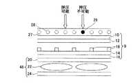
図18は、所定の機能の発現に必要なキー以外のキー入力があった場合にバイオメタルファイバー28に電圧を印加する例である。 FIG. 18 is an example in which a voltage is applied to the
所定の機能の発現に必要なキー以外のキー入力の例としては、電話番号としてあり得ない11桁以上の数字を入力した場合があるが、この場合にはこれ以上の数字の入力はありえないので、図18(a)のように全ての数字部分のバイオメタルファイバー28に電圧を印加してその旨を伝える。
また、選択肢が1〜9の範囲に限られる場合に、「*」「0」「#」が押された時には、図18(b)のように、「*」「0」「#」部分のバイオメタルファイバー28に電圧を印加して、「*」「0」「#」は選択不能であることをユーザに知らせる。As an example of key input other than the keys necessary for the expression of a predetermined function, there is a case where a number of 11 or more digits which cannot be used as a telephone number is input. In this case, it is impossible to input a number more than this. As shown in FIG. 18 (a), a voltage is applied to the
When the options are limited to the range of 1 to 9, when “*”, “0”, “#” is pressed, the “*”, “0”, “#” portion is displayed as shown in FIG. A voltage is applied to the
「変形例その4」
上記変形例その3では、単に、所定の機能の発現に必要なキー以外のキー入力であった場合にのみ、バイオメタルファイバー28に電圧を印加してユーザに触覚的に認識させていた。
しかし、バイオメタルファイバー28に電圧を印加することによって突起部分38を形成し、この突起部分38が入力キーを押した指等を押し返すことによって、ユーザに何らかのメッセージを伝えるという技術的思想は他にも応用が可能である。
つまり、ユーザに対するインターフェースの一つとして機能させることができる。
それゆえ、たとえば、突起部分38の形状によって一定のメッセージを伝えることが可能であるし、突起部分38の形状をより高度に制御すれば点字、文字、図形等を表示させることもできる。
さらに、道路案内の時には道路の形状に合わせて突起部分38を形成して触覚的にも道路形状を認識するようにすることもできる。
また、音楽のリズムに合わせて突起部分38を作って聴覚のみならず触覚的にも音楽を楽しむことが可能である。
なお、後述する変形例その6の部分で記載する実施態様では、突起部分38の形状は任意に形成することが可能である。“
In the third modification, a voltage is applied to the
However, there is another technical idea that a protruding
That is, it can function as one of the interfaces for the user.
Therefore, for example, it is possible to convey a certain message according to the shape of the protruding
Further, when the road is guided, the
Further, it is possible to enjoy the music not only by hearing but also by tactile sensation by making the protruding
In the embodiment described in the sixth modification example described later, the shape of the protruding
「変形例その5」
図19は、本発明の変形例その5を説明するための説明図である。
前述したタッチパネル式ディスプレイ8の構成は図7のように、バイオメタルファイバー28、タッチパネル9、表示部48の順に表面側から積み重ねられていた。
このような構成となっているのは通常の液晶パネルは表面側パネル20及び内部側パネル24は通常ガラス部材から構成されることから、バイオメタルファイバー28へ電圧を印加することによって発生する突起部分38による表面形状の変化に耐えられないからである。
しかし、現在では液晶パネルにおいても表面の形状の変化(曲げなど)に対応することが可能となっている。さらにOLEDなどでも形状の変化が可能な表示部48が開発されている。
したがって、バイオメタルファイバー28、タッチパネル9、表示部48の順に表面側から積み重ねる必要性は必ずしもない。
そこで、図19のように、表示部48、バイオメタルファイバー28、タッチパネル9の順に表面側から積み重ねることができる。"
FIG. 19 is an explanatory diagram for explaining a fifth modification of the present invention.
The configuration of the touch
This is because a normal liquid crystal panel has a
However, it is now possible to cope with surface shape changes (bending, etc.) even in liquid crystal panels. Further, a
Therefore, it is not always necessary to stack the
Therefore, as shown in FIG. 19, the
ところで、タッチパネル9は透明な材質、または、表示部48の表示光を遮らないような微細な部材によって形成されている。また、表示部48の表示光を遮らないような微細な部材によって形成されているということは、バイオメタルファイバー28及びバイオメタルファイバー含有フィルム27であっても同様である。
しかし、透明な材料及び微細な部材であっても表示部48の表面側にあれば、僅かに光を遮断する。
それゆえ、表示部48の表面側にはできるだけ部材を配置しないことが望ましい。
そこで、図19のように、表示部48の表面側には部材を配置せず、表示部48、バイオメタルファイバー28、タッチパネル9の順に表面側から積み重ねている。By the way, the
However, even if it is a transparent material and a fine member, if it is on the surface side of the
Therefore, it is desirable to dispose as many members as possible on the surface side of the
Therefore, as shown in FIG. 19, no member is arranged on the surface side of the
「変形例その6」
本発明の技術的思想の本質は、タッチパネル式ディスプレイ8の表面に凹凸を生じさせて、ユーザにこの凹凸を認識させることである。
そうすると、タッチパネル式ディスプレイ8の表面に凹凸を形成する方法は、バイオメタルファイバー28に電圧を印加するという方法にとどまるものではなく他の方法によることもできる。"
The essence of the technical idea of the present invention is to generate irregularities on the surface of the
Then, the method of forming irregularities on the surface of the
図20は、タッチパネル式ディスプレイ8の表面に突起部分38を形成する方法の一例を説明する説明図である。 FIG. 20 is an explanatory diagram for explaining an example of a method for forming the protruding
図20(a)では、表示部48の表面に空洞42を形成しておき、内部に圧縮空気又は液体を流し込み、空洞42を膨らませて膨張空洞43を形成している。
空洞42を小さく形成し、タッチパネル式ディスプレイ8の全面に多数配置すれば、任意の形状の突起部分38を形成可能である。In FIG. 20A, a
If the
また、通常は空洞42に圧縮空気又は液体を流し込んで膨張空洞43としておき、形状を形成したい部分の膨張空洞43から圧縮空気又は液体を排出して、窪みを形成することも可能である。 Ordinarily, compressed air or liquid can be poured into the
図20(b)では、表示部48の表面に電荷を帯びた帯電物質44配置し、これに電磁石45によって磁場をかけることによって、表示部48の表面に突起部分38を形成している。
電磁石45を小さく形成し、タッチパネル式ディスプレイ8の全面に多数配置すれば、任意の形状の突起部分38を形成可能である。In FIG. 20B, a charged
If the
[変形例その7]
図21では、図9における電源34を変圧電源53に変更する。このように、電圧を任意に変更して、バイオメタルファイバー28に流れる電流を変更する。
このように、バイオメタルファイバー28に流れる電流を変更すると、その電流に応じて、バイオメタルファイバー28が緊張・収縮して、強度が高くなる程度を調整することができる。
この機能を利用して、タッチパネル式ディスプレイ8における突起部分38の突起量を調整することができる。
さらに、突起部分38の突起する速さも変更できるのであるから、ユーザが押し返されると感じる程度を変更することができる。
この機能によって、ユーザに一定の情報を通知するインターフェースとしての用いることができる。[Modification 7]
In FIG. 21, the
As described above, when the current flowing through the
Using this function, the projection amount of the
Furthermore, since the protruding speed of the protruding
This function can be used as an interface for notifying the user of certain information.
以上の実施形態によれば、複数の入力キー配置を切替表示する表示部48と、表示部48に重畳して配置されるタッチパネル9と、複数の入力キー配置において表示される入力キーの境界線に沿って、タッチパネル9と表示部48との間に配置され、通電状態に応じて緊張収縮、弛緩伸張するバイオメタルファイバー28とを有する。
そして、表示部48に現在表示されている入力キーの境界線に沿うバイオメタルファイバー28が緊張収縮するよう、バイオメタルファイバー28への前記通電状況を制御する制御部46と、を有する。
そして、表示部48に現在表示されている入力キーの境界線に沿うバイオメタルファイバー28が緊張収縮するよう、バイオメタルファイバー28への通電状態を制御する制御部46と、を有する。
このような構成によって、視覚に障害のあるユーザであってもキー入力を確実に行うことができる。また、視覚に障害のないユーザも触覚的にキーの範囲を認識することができるのであるから、より確実にキー入力を行うことができる。According to the above embodiment, the
And the
And it has the
With such a configuration, even a visually impaired user can reliably perform key input. In addition, since the user who is not visually impaired can also recognize the key range tactilely, it is possible to perform key input more reliably.
制御部46は、通電するバイオメタルファイバー28の数を、表示部48に現在表示されている個別の入力キーの面積に応じて変化させる。
このような構成によって、入力キーが十分な面積を有している時には突起部分38を十分に取って、入力キーの境界を強調することができる。
一方、入力キーの面積が狭い時には入力キーの境界を狭く取って入力キーの面積をできるだけ広くすることができる。The
With such a configuration, when the input key has a sufficient area, the
On the other hand, when the area of the input key is small, the boundary of the input key can be narrowed to make the area of the input key as large as possible.
複数の入力キー配置を切替表示可能な表示部48と、表示部48に重畳して配置されるタッチパネル9と、タッチパネル9の被操作面側に配置され、通電状態に応じて緊張収縮、弛緩伸張するバイオメタルファイバー28と、を有する。
そして、バイオメタルファイバー28が緊張収縮するよう、バイオメタルファイバー28への前記通電状態を制御する制御部46と、を有する。
このような構成によって、タッチパネル式ディスプレイ8の表面に突起部分38を形成することができる。そして、この突起部分38はユーザに様々な情報を伝達するインターフェースの役割を果たすことができる。A
And it has the
With such a configuration, the protruding
制御部46は、表示部48に現在表示されている入力キーの境界線に沿っているバイオメタルファイバー28が緊張収縮するように前記通電状態を制御する。
このような構成によって、視覚に障害のあるユーザであってもキー入力を確実に行うことができる。また、視覚に障害のないユーザも触覚的にキーの範囲を認識することができるのであるから、より確実にキー入力を行うことができる。The
With such a configuration, even a visually impaired user can reliably perform key input. In addition, since the user who is not visually impaired can also recognize the key range tactilely, it is possible to perform key input more reliably.
制御部46は、通電するバイオメタルファイバー28の数を、表示部48に現在表示されている個別の入力キーの面積に応じて変化させる。
このような構成によって、入力キーが十分な面積を有している時には突起部分38を十分に取って、入力キーの境界を強調することができる。一方、入力キーの面積が狭い時には入力キーの境界を狭く取って入力キーの面積をできるだけ広くすることができる。The
With such a configuration, when the input key has a sufficient area, the
制御部46は、複数の入力キーが同時に押圧されている場合には、当該複数の押圧されている入力キー内部に配置されているバイオメタルファイバー28に通電する。
このような構成によって、ユーザに複数の入力キーを跨って入力を行っていることを知らせることができる。
そして、ユーザは改めてキー入力をやり直すことができる。When a plurality of input keys are pressed at the same time, the
With such a configuration, it is possible to notify the user that input is performed across a plurality of input keys.
Then, the user can perform key input again.
制御部46は、所定の機能の発現に必要な入力キー以外が押圧されている場合には、すくなくとも当該押圧されている入力キー内部に配置されているバイオメタルファイバー28に通電する。
このような構成によって、ユーザは入力できないキーを押していることを認識することができる。
そして、ユーザは改めてキー入力をやり直す、又は、キー入力を取りやめることができる。When a key other than an input key required for the expression of a predetermined function is pressed, the
With such a configuration, it is possible to recognize that the user is pressing a key that cannot be input.
Then, the user can redo the key input or cancel the key input.
また、複数の入力キー配置を切替表示可能な表示部48と、表示部48に重畳して配置されるタッチパネル9と、被操作面である表面に突起または窪みを形成可能なバイオメタルファイバー28、駆動回路(段落(0027))、空洞42、膨張空洞43、帯電物質44、電磁石45と、表示部48に現在表示されている入力キーに応じて、空洞42、膨張空洞43、帯電物質44、電磁石45を制御して、被操作面に突起または窪みを形成する制御部46と、を有する。
このような構成によって、視覚に障害のあるユーザであってもキー入力を確実に行うことができる。また、視覚に障害のないユーザも触覚的にキーの範囲を認識することができるのであるから、より確実にキー入力を行うことができる。In addition, a
With such a configuration, even a visually impaired user can reliably perform key input. In addition, since the user who is not visually impaired can also recognize the key range tactilely, it is possible to perform key input more reliably.
なお、以上の実施形態において、バイオメタルファイバー28は本発明の繊維材料の一例であり、電圧の印加によって緊張収縮又は弛緩伸張するものであればどのようなものであってもよい。また、金属材料は本発明の繊維材料の一例である。
バイオメタルファイバー28、駆動回路、空洞42、膨張空洞43、帯電物質44、電磁石45は、本発明の表面形状形成部の一例である。表明形状形成部51は、これらによる方法に限定されず、突起部分38を形成可能なものであればどのようなものであってもよい。In the above embodiment, the
The
本発明は、以上の実施形態に限定されず、種々の態様で実施されてよい。 The present invention is not limited to the above embodiment, and may be implemented in various aspects.
入力装置は、携帯電話機1のタッチパネルに限定されない。
例えば、入力装置は、パソコンのタッチパネル、ノートパソコンのタッチパネル、PDAのタッチパネル、ゲーム機のタッチパネル、カメラ機のタッチパネル、テレビジョンのタッチパネル、各種測定器のタッチパネル、公共施設等に設置されている案内用の機器のタッチパネル、などのタッチパネルを利用している全ての機器及びタッチパネルを今後利用可能な全ての機器の入力装置をいう。
また、携帯電話機1は、折り畳み式のものに限定されない。ケースが一体的に構成されたもの(1つのみのケース)であってもよい。The input device is not limited to the touch panel of the
For example, the input device is a touch panel of a personal computer, a touch panel of a laptop computer, a touch panel of a PDA, a touch panel of a game machine, a touch panel of a camera machine, a touch panel of a television, a touch panel of various measuring instruments, a guidance facility installed in a public facility, etc. An input device for all devices that use a touch panel, such as a touch panel of the device, and all devices that can use the touch panel in the future.
Further, the
1…携帯電話機、2…第1筐体、3…第2筐体、4…第1筐体フロントケース、5…第1筐体リアケース、6…第2筐体フロントケース、7…第2筐体リアケース、8…タッチパネル式ディスプレイ、9…タッチパネル、10…表面側フィルム、12…表面側導電膜、14…内部側導電膜、16…内部側フィルム、18…ドットスペーサ、20…表面側パネル、22…液晶部材、24…内部側パネル、27…バイオメタルファイバー含有フィルム、28…バイオメタルファイバー、29…通電バイオメタルファイバー、32…スイッチ、34…電源、36…固定部材、38…突起部分、40…平坦部分、42…空洞、43…膨張空洞、44…帯電物質、45…電磁石、46…制御部、47…操作部、48…表示部、49…通信部、50…記憶部、51…表面形状形成部、52…システムバス、53…変圧電源DESCRIPTION OF
Claims (7)
Translated fromJapanese前記表示部に重畳して配置されるタッチパネルと、
通電状態に応じて緊張収縮、弛緩伸張する繊維材料と、
前記表示部に現在表示されている入力キーの境界部分の前記繊維材料が緊張収縮するよう、前記繊維材料への前記通電状態を制御する制御部と、
を有し、
前記制御部は、通電する前記繊維材料の数を、前記表示部に現在表示されている個別の入力キーの面積に応じて変化させる、
入力装置。A display unit for switching and displaying a plurality of input key arrangements;
A touch panel arranged to be superimposed on the display unit;
A fiber material that stretches and contracts and relaxes depending on the energized state;
A control unit for controlling the energized state of the fiber material so that the fiber material at the boundary portion of the input key currently displayed on the display unit is contracted;
I have a,
The control unit changes the number of the fiber materials to be energized according to the area of individual input keys currently displayed on the display unit,
Input devices.
前記表示部に重畳して配置されるタッチパネルと、
通電状態に応じて緊張収縮、弛緩伸張する繊維材料と、
前記表示部に現在表示されている入力キーの境界部分の前記繊維材料が緊張収縮するよう、前記繊維材料への前記通電状態を制御する制御部と、
を有し、
前記制御部は、複数の入力キーが同時に押圧されている場合には、当該複数の押圧されている入力キー内部に配置されている前記繊維材料に通電する、
入力装置。A display unit for switching and displaying a plurality of input key arrangements;
A touch panel arranged to be superimposed on the display unit;
A fiber material that stretches and contracts and relaxes depending on the energized state;
A control unit for controlling the energized state of the fiber material so that the fiber material at the boundary portion of the input key currently displayed on the display unit is contracted;
I have a,
When the plurality of input keys are pressed at the same time, the control unit energizes the fiber material disposed inside the plurality of pressed input keys.
Input devices.
前記表示部に重畳して配置されるタッチパネルと、
通電状態に応じて緊張収縮、弛緩伸張する繊維材料と、
前記表示部に現在表示されている入力キーの境界部分の前記繊維材料が緊張収縮するよう、前記繊維材料への前記通電状態を制御する制御部と、
を有し、
前記制御部は、所定の機能の発現に必要な入力キー以外が押圧されている場合には、少なくとも当該押圧されている入力キー内部に配置されている前記繊維材料に通電する、
入力装置。A display unit for switching and displaying a plurality of input key arrangements;
A touch panel arranged to be superimposed on the display unit;
A fiber material that stretches and contracts and relaxes depending on the energized state;
A control unit for controlling the energized state of the fiber material so that the fiber material at the boundary portion of the input key currently displayed on the display unit is contracted;
I have a,
The controller is energized to at least the fiber material disposed inside the input key that is pressed when a key other than an input key required for the expression of a predetermined function is pressed.
Input devices.
前記表示部に重畳して配置されるタッチパネルと、
前記複数の入力キー配置において表示される入力キーの境界線に沿って、前記タッチパネルと前記表示部との間に配置され、通電状態に応じて緊張収縮、弛緩伸張する繊維材料と、
前記表示部に現在表示されている入力キーの境界線に沿う前記繊維材料が緊張収縮するよう、前記繊維材料への前記通電状態を制御する制御部と、
を有し、
前記制御部は、通電する前記繊維材料の数を、前記表示部に現在表示されている個別の入力キーの面積に応じて変化させる、
入力装置。A display unit for switching and displaying a plurality of input key arrangements;
A touch panel arranged to be superimposed on the display unit;
A fiber material that is arranged between the touch panel and the display unit along a boundary line of input keys displayed in the plurality of input key arrangements, and that contracts and contracts according to the energized state,
A control unit that controls the energization state of the fiber material so that the fiber material along the boundary line of the input key currently displayed on the display unit is contracted;
Have
The control unit changes the number of the fiber materials to be energized according to the area of individual input keys currently displayed on the display unit,
Input device.
前記表示部に重畳して配置されるタッチパネルと、
前記タッチパネルの被操作面側に配置され、通電状態に応じて緊張収縮、弛緩伸張する繊維材料と、
前記繊維材料が緊張収縮するよう、前記繊維材料への前記通電状態を制御する制御部と、
を有し、
前記制御部は、前記表示部に現在表示されている入力キーの境界線に沿っている前記繊維材料が緊張収縮するように前記通電状態を制御し、
前記制御部は、通電する前記繊維材料の数を、前記表示部に現在表示されている個別の入力キーの面積に応じて変化させる、
入力装置。A display unit capable of switching and displaying a plurality of input key arrangements;
A touch panel arranged to be superimposed on the display unit;
A fiber material that is arranged on the operated surface side of the touch panel, and that contracts and relaxes according to the energized state, and
A control unit for controlling the energized state of the fiber material so that the fiber material is tensioned and contracted;
Have
The control unit controls the energized state so that the fiber material along the boundary line of the input key currently displayed on the display unit is contracted.
The control unit changes the number of the fiber materials to be energized according to the area of individual input keys currently displayed on the display unit,
Input device.
前記表示部に重畳して配置されるタッチパネルと、
前記タッチパネルの被操作面側に配置され、通電状態に応じて緊張収縮、弛緩伸張する繊維材料と、
前記繊維材料が緊張収縮するよう、前記繊維材料への前記通電状態を制御する制御部と、
を有し、
前記制御部は、複数の入力キーが同時に押圧されている場合には、当該複数の押圧されている入力キー内部に配置されている前記繊維材料に通電する、
入力装置。A display unit capable of switching and displaying a plurality of input key arrangements;
A touch panel arranged to be superimposed on the display unit;
A fiber material that is arranged on the operated surface side of the touch panel, and that contracts and relaxes according to the energized state, and
A control unit for controlling the energized state of the fiber material so that the fiber material is tensioned and contracted;
Have
When the plurality of input keys are pressed at the same time, the control unit energizes the fiber material disposed inside the plurality of pressed input keys.
Input device.
前記表示部に重畳して配置されるタッチパネルと、
前記タッチパネルの被操作面側に配置され、通電状態に応じて緊張収縮、弛緩伸張する繊維材料と、
前記繊維材料が緊張収縮するよう、前記繊維材料への前記通電状態を制御する制御部と、
を有し、
前記制御部は、所定の機能の発現に必要な入力キー以外が押圧されている場合には、少なくとも当該押圧されている入力キー内部に配置されている前記繊維材料に通電する、
入力装置。A display unit capable of switching and displaying a plurality of input key arrangements;
A touch panel arranged to be superimposed on the display unit;
A fiber material that is arranged on the operated surface side of the touch panel, and that contracts and relaxes according to the energized state, and
A control unit for controlling the energized state of the fiber material so that the fiber material is tensioned and contracted;
Have
The controller is energized to at least the fiber material disposed inside the input key that is pressed when a key other than an input key required for the expression of a predetermined function is pressed.
Input device.
Priority Applications (1)
| Application Number | Priority Date | Filing Date | Title |
|---|---|---|---|
| JP2009016907AJP5323512B2 (en) | 2009-01-28 | 2009-01-28 | Input device |
Applications Claiming Priority (1)
| Application Number | Priority Date | Filing Date | Title |
|---|---|---|---|
| JP2009016907AJP5323512B2 (en) | 2009-01-28 | 2009-01-28 | Input device |
Publications (2)
| Publication Number | Publication Date |
|---|---|
| JP2010176299A JP2010176299A (en) | 2010-08-12 |
| JP5323512B2true JP5323512B2 (en) | 2013-10-23 |
Family
ID=42707237
Family Applications (1)
| Application Number | Title | Priority Date | Filing Date |
|---|---|---|---|
| JP2009016907AExpired - Fee RelatedJP5323512B2 (en) | 2009-01-28 | 2009-01-28 | Input device |
Country Status (1)
| Country | Link |
|---|---|
| JP (1) | JP5323512B2 (en) |
Families Citing this family (11)
| Publication number | Priority date | Publication date | Assignee | Title |
|---|---|---|---|---|
| US8704790B2 (en)* | 2010-10-20 | 2014-04-22 | Tactus Technology, Inc. | User interface system |
| JPWO2012093725A1 (en)* | 2011-01-07 | 2014-06-09 | 日本電気株式会社 | Tablet device and tactile sense presentation method |
| JP5773214B2 (en)* | 2011-12-27 | 2015-09-02 | アイシン・エィ・ダブリュ株式会社 | Input system |
| JP5920187B2 (en)* | 2012-11-22 | 2016-05-18 | ブラザー工業株式会社 | Operation area creation device |
| CN103207672B (en) | 2013-03-04 | 2015-11-25 | 小米科技有限责任公司 | Physical feedback system, control method, device, display assembly and electronic equipment |
| JP6006679B2 (en)* | 2013-05-20 | 2016-10-12 | 日本電信電話株式会社 | Interface and information processing apparatus |
| JP2014075146A (en)* | 2013-12-03 | 2014-04-24 | Nec Casio Mobile Communications Ltd | Mobile terminal device |
| JP6237927B2 (en)* | 2014-10-27 | 2017-11-29 | 株式会社村田製作所 | Tactile presentation device |
| JP7043039B2 (en) | 2015-09-30 | 2022-03-29 | テンパール工業株式会社 | Portable measuring instrument |
| JP6139647B1 (en) | 2015-12-11 | 2017-05-31 | レノボ・シンガポール・プライベート・リミテッド | Information processing apparatus, input determination method, and program |
| EP3299939B1 (en) | 2016-09-27 | 2019-05-08 | Alpine Electronics, Inc. | Input apparatus with touch sensitive input device |
Family Cites Families (2)
| Publication number | Priority date | Publication date | Assignee | Title |
|---|---|---|---|---|
| JP2006243812A (en)* | 2005-02-28 | 2006-09-14 | Kyocera Mita Corp | Touch panel, and display input device with touch panel |
| JP4555265B2 (en)* | 2006-07-28 | 2010-09-29 | アルプス電気株式会社 | Input device |
- 2009
- 2009-01-28JPJP2009016907Apatent/JP5323512B2/ennot_activeExpired - Fee Related
Also Published As
| Publication number | Publication date |
|---|---|
| JP2010176299A (en) | 2010-08-12 |
Similar Documents
| Publication | Publication Date | Title |
|---|---|---|
| JP5323512B2 (en) | Input device | |
| EP2600227B1 (en) | Input device | |
| JP5635274B2 (en) | Tactile sensation presentation apparatus and tactile sensation presentation method | |
| US9727177B2 (en) | Electronic device with a touch sensor | |
| US10795492B2 (en) | Input device and method for controlling input device | |
| KR20120047982A (en) | Input device and method for controlling input device | |
| CN101491127A (en) | Method for configuring terminal keyboard, terminal and system including terminal and reconfigurable keyboard | |
| US20090267900A1 (en) | Operation method of user interface and computer readable medium and portable device | |
| WO2012086208A1 (en) | Electronic device | |
| JP2012108915A (en) | External input device for electrostatic capacitance type touch panel | |
| JPWO2013046670A1 (en) | Tactile presentation device | |
| JP5099040B2 (en) | Information processing device | |
| JP5539788B2 (en) | Tactile presentation device | |
| US8884880B2 (en) | Apparatus and method for providing visual-haptic information, and terminal having the same | |
| JP5623054B2 (en) | Input device | |
| JP2010176438A (en) | Display device with touch switch | |
| US9804674B2 (en) | Tactile sensation providing apparatus | |
| WO2011077687A1 (en) | Force-feedback device and control method for a force-feedback device | |
| JP2011090615A (en) | Tactile communication device and display device provided with the same | |
| GB2382291A (en) | Overlay for touch sensitive screen | |
| JP5660611B2 (en) | Electronic device, character input method, and program | |
| KR100563460B1 (en) | Touch panel integrated liquid crystal display and its driving method | |
| JP2013205986A (en) | Electronic device | |
| JP2012113646A (en) | Tactile sense presentation device | |
| JP5734621B2 (en) | Input device |
Legal Events
| Date | Code | Title | Description |
|---|---|---|---|
| A621 | Written request for application examination | Free format text:JAPANESE INTERMEDIATE CODE: A621 Effective date:20111227 | |
| A977 | Report on retrieval | Free format text:JAPANESE INTERMEDIATE CODE: A971007 Effective date:20121205 | |
| A131 | Notification of reasons for refusal | Free format text:JAPANESE INTERMEDIATE CODE: A131 Effective date:20121211 | |
| A521 | Request for written amendment filed | Free format text:JAPANESE INTERMEDIATE CODE: A523 Effective date:20130208 | |
| A02 | Decision of refusal | Free format text:JAPANESE INTERMEDIATE CODE: A02 Effective date:20130226 | |
| A521 | Request for written amendment filed | Free format text:JAPANESE INTERMEDIATE CODE: A523 Effective date:20130527 | |
| A911 | Transfer to examiner for re-examination before appeal (zenchi) | Free format text:JAPANESE INTERMEDIATE CODE: A911 Effective date:20130603 | |
| TRDD | Decision of grant or rejection written | ||
| A01 | Written decision to grant a patent or to grant a registration (utility model) | Free format text:JAPANESE INTERMEDIATE CODE: A01 Effective date:20130618 | |
| A61 | First payment of annual fees (during grant procedure) | Free format text:JAPANESE INTERMEDIATE CODE: A61 Effective date:20130717 | |
| R150 | Certificate of patent or registration of utility model | Ref document number:5323512 Country of ref document:JP Free format text:JAPANESE INTERMEDIATE CODE: R150 Free format text:JAPANESE INTERMEDIATE CODE: R150 | |
| LAPS | Cancellation because of no payment of annual fees |