JP5323194B2 - Medical image processing apparatus and method - Google Patents
Medical image processing apparatus and methodDownload PDFInfo
- Publication number
- JP5323194B2 JP5323194B2JP2011527494AJP2011527494AJP5323194B2JP 5323194 B2JP5323194 B2JP 5323194B2JP 2011527494 AJP2011527494 AJP 2011527494AJP 2011527494 AJP2011527494 AJP 2011527494AJP 5323194 B2JP5323194 B2JP 5323194B2
- Authority
- JP
- Japan
- Prior art keywords
- cross
- sectional
- image
- medical image
- positional relationship
- Prior art date
- Legal status (The legal status is an assumption and is not a legal conclusion. Google has not performed a legal analysis and makes no representation as to the accuracy of the status listed.)
- Active
Links
Images


Classifications
- G—PHYSICS
- G06—COMPUTING OR CALCULATING; COUNTING
- G06T—IMAGE DATA PROCESSING OR GENERATION, IN GENERAL
- G06T19/00—Manipulating 3D models or images for computer graphics
- A—HUMAN NECESSITIES
- A61—MEDICAL OR VETERINARY SCIENCE; HYGIENE
- A61B—DIAGNOSIS; SURGERY; IDENTIFICATION
- A61B6/00—Apparatus or devices for radiation diagnosis; Apparatus or devices for radiation diagnosis combined with radiation therapy equipment
- A61B6/52—Devices using data or image processing specially adapted for radiation diagnosis
- A61B6/5211—Devices using data or image processing specially adapted for radiation diagnosis involving processing of medical diagnostic data
- A61B6/5223—Devices using data or image processing specially adapted for radiation diagnosis involving processing of medical diagnostic data generating planar views from image data, e.g. extracting a coronal view from a 3D image
- A—HUMAN NECESSITIES
- A61—MEDICAL OR VETERINARY SCIENCE; HYGIENE
- A61B—DIAGNOSIS; SURGERY; IDENTIFICATION
- A61B8/00—Diagnosis using ultrasonic, sonic or infrasonic waves
- A61B8/52—Devices using data or image processing specially adapted for diagnosis using ultrasonic, sonic or infrasonic waves
- A61B8/5215—Devices using data or image processing specially adapted for diagnosis using ultrasonic, sonic or infrasonic waves involving processing of medical diagnostic data
- A61B8/523—Devices using data or image processing specially adapted for diagnosis using ultrasonic, sonic or infrasonic waves involving processing of medical diagnostic data for generating planar views from image data in a user selectable plane not corresponding to the acquisition plane
- A—HUMAN NECESSITIES
- A61—MEDICAL OR VETERINARY SCIENCE; HYGIENE
- A61B—DIAGNOSIS; SURGERY; IDENTIFICATION
- A61B5/00—Measuring for diagnostic purposes; Identification of persons
- A61B5/05—Detecting, measuring or recording for diagnosis by means of electric currents or magnetic fields; Measuring using microwaves or radio waves
- A61B5/055—Detecting, measuring or recording for diagnosis by means of electric currents or magnetic fields; Measuring using microwaves or radio waves involving electronic [EMR] or nuclear [NMR] magnetic resonance, e.g. magnetic resonance imaging
- A—HUMAN NECESSITIES
- A61—MEDICAL OR VETERINARY SCIENCE; HYGIENE
- A61B—DIAGNOSIS; SURGERY; IDENTIFICATION
- A61B6/00—Apparatus or devices for radiation diagnosis; Apparatus or devices for radiation diagnosis combined with radiation therapy equipment
- A61B6/02—Arrangements for diagnosis sequentially in different planes; Stereoscopic radiation diagnosis
- A61B6/03—Computed tomography [CT]
- G—PHYSICS
- G06—COMPUTING OR CALCULATING; COUNTING
- G06T—IMAGE DATA PROCESSING OR GENERATION, IN GENERAL
- G06T2219/00—Indexing scheme for manipulating 3D models or images for computer graphics
- G06T2219/008—Cut plane or projection plane definition
- G—PHYSICS
- G06—COMPUTING OR CALCULATING; COUNTING
- G06T—IMAGE DATA PROCESSING OR GENERATION, IN GENERAL
- G06T2219/00—Indexing scheme for manipulating 3D models or images for computer graphics
- G06T2219/028—Multiple view windows (top-side-front-sagittal-orthogonal)
Landscapes
- Engineering & Computer Science (AREA)
- Health & Medical Sciences (AREA)
- Life Sciences & Earth Sciences (AREA)
- Medical Informatics (AREA)
- Physics & Mathematics (AREA)
- Animal Behavior & Ethology (AREA)
- Nuclear Medicine, Radiotherapy & Molecular Imaging (AREA)
- Pathology (AREA)
- Radiology & Medical Imaging (AREA)
- Biomedical Technology (AREA)
- Heart & Thoracic Surgery (AREA)
- Biophysics (AREA)
- Molecular Biology (AREA)
- Surgery (AREA)
- Computer Vision & Pattern Recognition (AREA)
- General Health & Medical Sciences (AREA)
- Public Health (AREA)
- Veterinary Medicine (AREA)
- High Energy & Nuclear Physics (AREA)
- Optics & Photonics (AREA)
- Computer Graphics (AREA)
- Computer Hardware Design (AREA)
- General Engineering & Computer Science (AREA)
- Software Systems (AREA)
- General Physics & Mathematics (AREA)
- Theoretical Computer Science (AREA)
- Magnetic Resonance Imaging Apparatus (AREA)
- Ultra Sonic Daignosis Equipment (AREA)
- Apparatus For Radiation Diagnosis (AREA)
- Processing Or Creating Images (AREA)
- Image Generation (AREA)
Description
Translated fromJapanese本発明は、3次元の医用画像データから、所望の断面を表示する医用画像処理技術に関する。 The present invention relates to a medical image processing technique for displaying a desired cross section from three-dimensional medical image data.
特許文献1は、X線CTやMRI等が撮影した3次元の医用画像データから複数の所望の断面位置を設定する。そして、特許文献1は、この医用画像データから、部位毎に診断する際には、診断する部位について所望の断面を設定する。
しかし、特許文献1では、前記所望の断面とその断面像の3次元空間中における大まかな位置のみを参照しているため、前記断面の空間的な位置の確認が十分に行えないという問題点があった。 However, in
そこで本発明は、上記問題点を解決するためになされたものであり、所望の断面の空間的な位置を簡単に確認できる医用画像処理装置及びその方法の提供を目的とする。 Accordingly, the present invention has been made to solve the above-described problems, and an object thereof is to provide a medical image processing apparatus and method for easily confirming a spatial position of a desired cross section.
本発明は、対象部位を含む3次元の医用画像データから、前記対象部位の複数の特徴部位を含む第1断面位置、前記第1断面位置と交差する第2断面位置、及び前記第1断面位置と前記第2断面位置との相対的な位置関係を示す位置関係情報を算出する算出部と、前記医用画像データと前記第1断面位置とを用いて第1断面像を、前記医用画像データと前記第2断面位置とを用いて第2断面像を生成する生成部と、前記第1断面像、及び前記第2断面像の少なくとも一方に、前記位置関係情報を合成する合成部と、前記合成した画像を表示する表示部と、を有することを特徴とする医用画像処理装置である。The present invention is, from three-dimensional medical image data including the target site,thefirst cross-sectional position including aplurality of featurespositionofsites,a second cross-sectional position that intersects the first section position, and the first section position a calculationunit for calculating the positional relationship information indicating a relative positional relationship between the location and the second cross-sectional position, thefirst sectional image using saidfirst cross-sectional position as the medical image data, the medical image A generating unit that generates asecond cross-sectional image using data andthe second cross-sectional position; a combining unit that combines the positional relationship information withat least one ofthe first cross-sectional imageandthesecond cross-sectional image; And a display unit that displays the synthesized image.
本発明によれば、基本断面の空間的な位置を簡単に確認できる。 According to the present invention, the spatial position of the basic cross section can be easily confirmed.
1・・医用画像処理装置、2・・基本位置算出部、3・・補助位置算出部、4・・生成部、5・・関係算出部、6・・表示部、7・・入力部、8・・修正部、9・・表示部1 .... Medical image processing device 2 .... Basic
以下、本発明の一実施例である医用画像処理装置1について図1〜図8を用いて説明する。 Hereinafter, a medical
本実施例は、X線CT、MRI、超音波等の医用画像診断装置に有用であり、特に、診断する部位について所望の空間位置での断面像が求められる場合に適している。 This embodiment is useful for medical image diagnostic apparatuses such as X-ray CT, MRI, and ultrasound, and is particularly suitable when a cross-sectional image at a desired spatial position is required for a site to be diagnosed.
本実施例では、診断対象の臓器を心臓とし、基本断面として「四腔断面像」を具体例として挙げる。「基本断面」とは、医師が診断に用いる所望の部位を含むように設定された断面である。なお、基本断面は四腔断面像に限定されず、例えば、「二腔断面像」や「左室短軸像」でも良い。 In this embodiment, the organ to be diagnosed is a heart, and a “four-chamber cross-sectional image” is given as a specific example as a basic cross section. The “basic cross section” is a cross section set so as to include a desired site used by a doctor for diagnosis. The basic cross section is not limited to the four-chamber cross-sectional image, and may be, for example, a “two-chamber cross-sectional image” or a “left ventricular short-axis image”.
医用画像処理装置1の構成について図1に基づいて説明する。図1は、医用画像処理装置1の構成を示すブロック図である。 The configuration of the medical
図1に示すように、医用画像処理装置1は、基本位置算出部2、補助位置算出部3、生成部4、関係算出部5、合成部6、入力部7、修正部8、表示部9を有している。 As shown in FIG. 1, the medical
X線CT、MRI、又は、超音波等の医用画像撮影装置から得られた3次元ボリュームデータである医用画像データが、基本位置算出部2、生成部4に入力される。 Medical image data, which is three-dimensional volume data obtained from a medical image photographing apparatus such as X-ray CT, MRI, or ultrasound, is input to the basic position calculation unit 2 and the
基本位置算出部2は、医用画像データから基本断面の空間的な位置を示す基本断面位置を算出する。 The basic position calculation unit 2 calculates a basic cross-sectional position indicating a spatial position of the basic cross-section from medical image data.
補助位置算出部3は、基本断面位置から、基本断面と交差する補助断面の空間的な位置を示す補助断面位置を算出する。 The auxiliary
生成部4は、基本断面位置と医用画像データを用いて基本断面像を生成し、また、補助断面位置と医用画像データを用いて補助断面像を生成する。 The generating
関係算出部5は、基本断面位置と補助断面位置の相対的な位置関係情報を算出する。 The
合成部6は、基本断面像と補助断面像とに、関係算出部5で算出された各断面の相対的な位置関係情報を合成し、表示部9に表示する。この表示部9は、液晶表示装置やCRTなどのディスプレイである。 The synthesizing unit 6 synthesizes the relative positional relationship information of each cross section calculated by the
入力部7は、基本断面像、補助断面像の位置関係情報に関する修正情報を入力する手段である。例えば、この入力部7は、マウスやキーボード、トラックボール、タッチパッドなどのユーザインタフェースにより実現される。 The
修正部8は、入力部7で受けた修正情報に基づいて、基本断面位置、補助断面位置を修正する。 The correcting
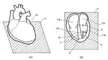
四腔断面像と心臓の特徴的な部位との関係について図2を用いて説明する。 The relationship between the four-chamber cross-sectional image and the characteristic part of the heart will be described with reference to FIG.
図2(a)は、四腔断面像の解剖学的な位置づけ10を示し、図2(b)は、四腔断面像11の例を示す。図2(b)に示すように、四腔断面像では、心臓の4つの腔(左心室11a、左心房11b、右心室11c、右心房11d)が全て含まれている。四腔断面像は、心臓の特徴部位である僧帽弁Aと心尖部C含む断面という知見がある。Bは「左室中心」と呼ばれる部位であり、僧帽弁Aと心尖部Cの中点に位置する。左室中心Bから心尖部Cへと向かうベクトルを長軸Yと呼ぶ。四腔断面像上で長軸Yと直交するベクトルを短軸Xと呼ぶ。 FIG. 2A shows the anatomical positioning 10 of the four-chamber cross-sectional image, and FIG. 2B shows an example of the four-chamber cross-sectional image 11. As shown in FIG. 2B, the four-chamber cross-sectional image includes all four chambers of the heart (
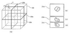
次に、3次元の医用画像データの3次元画像座標系(3次元画像空間座標系)を図4を用いて説明する。 Next, a three-dimensional image coordinate system (three-dimensional image space coordinate system) of three-dimensional medical image data will be described with reference to FIG.
図3(a)に示すように、3次元画像座標系における医用画像データが持つ3次元画像空間20は、3つの座標軸x、y、zで表現される。x軸が体の左から右、y軸が体の前から後ろ、z軸が体軸方向で足の方へ向かうベクトルとする。 As shown in FIG. 3A, the three-
図3(b)〜(d)に示すように、3次元画像空間20における各断面像21a、21b、21cは、医用画像データを座標軸に平行な面20a、20b、20cで切断した画像である。各断面20a、20b、20cは、それぞれ「Axial断面」、「Sagittal断面」、「Coronal断面」と呼び、各断面像21a、21b、21cは、それぞれ「Axial断面像」、「Sagittal断面像」、「Coronal断面像」と呼ぶ。 As shown in FIGS. 3B to 3D, the
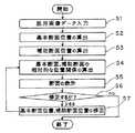
医用画像処理装置1の動作について図4を用いて説明する。図4は、医用画像処理装置の動作を示すフローチャートである。 The operation of the medical
ステップS1では、医用画像撮影装置が、3次元ボリュームデータである医用画像データを基本位置算出部2に出力する。なお、医用画像データは、各種の医用画像撮影装置から直接入力しても良いし、画像サーバ等に保存された画像データを入力しても良い。 In step S <b> 1, the medical image photographing apparatus outputs medical image data that is three-dimensional volume data to the basic position calculation unit 2. The medical image data may be input directly from various medical image capturing apparatuses, or image data stored in an image server or the like may be input.
ステップS2では、基本位置算出部2は、医用画像データから基本断面位置を算出する。そして、生成部4は、この基本断面位置と医用画像データから基本断面像を生成する。 In step S2, the basic position calculation unit 2 calculates the basic cross-sectional position from the medical image data. Then, the
「基本断面位置の算出」とは、3次元ボリュームデータの3次元画像空間20中に基本断面を設定することであり、その基本断面における画像(以下、「基本断面像」と呼ぶ)上に、診断に用いる所望の部位を含むように設定する。また、「基本断面位置」とは、3次元画像空間20において基本断面の空間的な位置を意味し、また、3次元ボリュームデータから基本断面像が一意に求まる位置パラメータで表される。例えば、この位置パラメータとしては、式(1)で決まる3次元画像空間20上での基本断面の中心座標点oと、式(2)で決まる基本断面上にある直交する2本のベクトルu,vである。
なお、この2本のベクトルu,vは、平行でなければ基本断面像を一意に決めることができる。しかし、本実施例では説明の便宜上、直交する2本のベクトルu,vで表現する。すなわち、基本断面位置の算出とは、この位置パラメータo,u,vを求めることである。 If the two vectors u and v are not parallel, the basic cross-sectional image can be uniquely determined. However, in this embodiment, it is expressed by two orthogonal vectors u and v for convenience of explanation. That is, the calculation of the basic cross-sectional position is to obtain the position parameters o, u, v.
また、基本断面位置の算出は、例えば、特許文献1で示すように手動で算出しても良いし、また、特開2002−140689号公報で開示されている手法を用いて自動で算出しても良い。 The basic cross-sectional position may be calculated manually, for example, as shown in
生成部4は、基本断面位置が算出されると、この基本断面位置と医用画像データから基本断面像を生成する。 When the basic cross-sectional position is calculated, the
図5(a)は、3次元画像空間20中で基本断面20dがどのように配置されるかを斜視図で示し、図5(b)は、生成された基本断面像21dの例を示す。図5(a)に示すように、基本断面位置は、例えば、3次元画像空間20における基本断面20dの中心座標点o20dと、基本断面20dに平行で直交する2本のベクトルu20d、v20dで表される。また、図5(a)の中心座標点o20dが図5(b)の画像中心点o21dに対応し、図5(a)のベクトルu20dが図5(b)における基本断面像21dの水平方向のベクトルi21dに対応し、図5(a)のベクトルv20dが図5(b)における基本断面像21dの垂直方向のベクトルj21dに対応している。なお、図中では、「u20d」と記載すると添え字が小さくなるため、「20d−u」と表示する。他のベクトルも同様に図中に記載する。FIG. 5A is a perspective view showing how the
ステップS3では、補助位置算出部3は、基本断面位置に基づいて補助断面位置を算出する。生成部4は、算出された補助断面位置と医用画像データから補助断面像を生成する。 In step S3, the auxiliary
「補助断面」とは、基本断面位置を、使用者が確認し易くするために補助的に求める断面であって、基本断面と交差する断面である。例えば、補助断面としては、基本断面と交差する断面であって、診断に用いる所望の部位を含むようなAxial断面やSagittal断面を使う。また、基本断面位置から相対的に算出される断面を補助断面とすることで、より効果的に基本断面位置を確認できる。 The “auxiliary cross section” is a cross section that is obtained in an auxiliary manner so that the user can easily confirm the basic cross section position, and is a cross section that intersects the basic cross section. For example, as the auxiliary cross section, an Axial cross section or a Sagittal cross section that intersects the basic cross section and includes a desired portion used for diagnosis is used. Moreover, the basic cross-section position can be confirmed more effectively by using the cross-section calculated relatively from the basic cross-section position as the auxiliary cross-section.
基本断面20dから相対的に補助断面20e、20f、20gを算出する方法について図6を用いて説明する。 A method of calculating the
基本断面20dの中心座標点o20dが式(3)のように設定される。
直交する2本のベクトルu20d、v20dが式(4)のように設定される。
このとき図6(a)に示すように、第1の補助断面20eは、3次元画像空間20のz軸と長軸Yに平行な面である。直交する2本のベクトルu20e、v20eは、式(5)のように表せる。
図6(b)に示すように、第2の補助断面20fは、第1の補助断面20eの法線ベクトルと長軸Yに平行な面である。直交する2本のベクトルu20f、v20fは、式(6)のように表せる。
なお、「×」は外積計算である。 Note that “×” is an outer product calculation.
図6(c)に示すように、第3の補助断面20gは、第1の補助断面20eの法線ベクトルと、第2の補助断面20fの法線ベクトルを含む面である。直交する2本のベクトルu20g、v20gは、式(7)のように表せる。
各補助断面20e、20f、20gの中心座標点o20e、o20f、o20gは、例えば、式(8)に示すように、基本断面20dの中心座標点を用いる。
このように、各補助断面20e、20f、20gは、基本断面20dから相対的に算出できる。 As described above, the
生成部4は、各補助断面位置から、図6(d)〜(f)に示すように、補助断面像21e、21f、21gを生成する。基本断面20dの基本断面像21dが四腔断面像の場合、補助断面20e、20f、20gより生成される補助断面像21e、21f、21gは、それぞれ「二腔断面像」、「水平断面像」、「左室短軸像」と呼ばれる。但し、補助断面はこれらに限るものではなく、診断対象の人間の体軸を基準に求めても良い。 The
このように、基本断面位置から相対的に算出することにより、心臓の特徴部位を含むような補助断面を設定しやすく、基本断面の確認が簡単な補助断面像を生成できる。 Thus, by calculating relatively from the basic cross-sectional position, it is easy to set an auxiliary cross-section that includes a characteristic part of the heart, and an auxiliary cross-sectional image that allows easy confirmation of the basic cross-section can be generated.
ステップS4では、関係算出部5は、基本断面20dと補助断面20e、20f、20gの相対的な位置関係情報を算出する。 In step S4, the
ここで、「位置関係情報」とは、例えば、基本断面と補助断面とが交差する線分、基本断面像と補助断面像に共通に含まれる特徴部位の空間的な座標点である。 Here, the “positional relationship information” is, for example, a line segment where the basic cross section and the auxiliary cross section intersect, a spatial coordinate point of a characteristic part that is commonly included in the basic cross sectional image and the auxiliary cross sectional image.
位置関係情報の算出例を図7(a)〜(d)を用いて説明する。 An example of calculating positional relationship information will be described with reference to FIGS.
関係算出部5は、図7(a)(b)(d)に示すように、基本断面20d、第2、3の補助断面像21e、21fは、長軸Yを含む互いに交差した面であるので、長軸Y(すなわち、基本断面像21d上の垂直方向)を示す線分v21d、v21e、v21fを算出する。また、基本位置算出部2が、僧帽弁A、左室中心B、心尖部Cの心臓に関する特徴部位の位置を算出しているときは、関係算出部5は、図7(a)(b)(d)の星印、四角印、三角印で表す座標点p21d、p21e、p21fで示すように、各断面上での各部位の位置を算出する。さらに、関係算出部5は、図7(c)に示すように、第3の補助断面20gは長軸Yと直交する面であるため、座標点p21g、線分v21gで示すように、第3の補助断面像21g上での短軸Xの方向を算出する。In the
このように、複数の断面が持つ共通の線分や、部位の座標点を算出することで、基本断面との相対的な位置関係情報を得ることができる。 As described above, by calculating the common line segments of the plurality of cross sections and the coordinate points of the parts, it is possible to obtain relative positional relationship information with the basic cross section.
ステップS5では、合成部6は、生成された基本断面像21d、補助断面像21e、21f、21gと、位置関係情報である線分や座標点を合成し、表示部9に表示する。 In step S <b> 5, the combining unit 6 combines the generated basic
例えば、合成部9は、図3、図5〜図7で示すAxial断面像20a、Sagittal断面像21b、Coronal断面像21c、基本断面像21d、補助断面像21e、21f、21gに、位置関係情報を重ねたり、3次元画像空間20での各断面の位置関係情報を、表示部9に表示する。 For example, the synthesizing unit 9 includes the positional relation information in the axial
ステップS6では、使用者が入力部7を操作して位置関係情報を修正し、修正部8が位置関係情報の修正を受け付けた場合はステップS7に進み(図4中の「yes」の場合)、使用者が修正をしなかった場合は終了する(図4中の「no」の場合)。 In step S6, when the user operates the
ステップS7では、修正部8は受け付けた位置関係情報の修正情報に基づいて、基本断面位置、補助断面位置を修正する。そして、ステップS4に戻り、関係算出部5が基本断面20dと補助断面20e、20f、20gの相対的な位置関係情報を再び算出する。 In step S7, the
修正について図8を用いて説明する。 The correction will be described with reference to FIG.
まず、合成部6は、図8(a)に示す3次元画像空間20での基本断面20d、図8(b)〜(d)に示す医用画像データのAxial断面像21a、Coronal断面像21b、Sagittal断面像21c、図8(e)〜(g)に示す補助断面像21e、21f、21g、図8(i)に示す基本断面像21dに、関係算出部5に算出された位置関係情報を合成し、表示部9に表示する。使用者は、表示部9を見ると、長軸Yは左室の中心を通るという医学的な知見があるため、第1の補助断面像21eからは長軸Yの左側を上方向に修正が必要なこと、第2の補助断面像21fからは長軸Yの左側を下方向に修正が必要なことが簡単に確認できる。また、第3の補助断面像21gは左室短軸像の例であり、短軸Xは左室l21gの中心を通り、右室r21gの左角を通るという医学的な知見があるため、第3の補助断面像21gからも簡単に修正すべき方向が確認できる。First, the synthesizing unit 6 includes a
次に、使用者がユーザインタフェースである入力部7のマウスを介して位置関係情報の修正を行う。例えば、使用者は、入力部7を操作することにより、基本断面と補助断面の位置関係情報である線分や座標点をポインタ30で指し、線分や座標点を画面上の上下左右に断面像毎に移動させる。修正部8は、この移動した情報を修正情報として受け付ける。すなわち、「修正情報」とは、断面像毎の位置関係情報である線分や座標点の移動方向と移動長さからなる2次元ベクトルである。 Next, the user corrects the positional relationship information via the mouse of the
次に、修正部8は、各断面像の2次元ベクトルの修正情報をそれぞれ用いて、2次元の断面像上の移動方向と移動長さを、3次元画像空間20の修正ベクトルに変換する。そして、変換した3次元の修正ベクトルに基づいて、基本断面位置を修正する。修正部8は、基本断面位置の位置パラメータo、u、vを次の式(9)に示す位置パラメータo’、u’、v’に修正する。
また、修正部8は、修正された基本断面位置の位置パラメータo’、u’、v’を用いて、式(5)〜式(9)を計算することにより、補助断面位置の位置パラメータを修正する。 The correcting
生成部4は、修正された基本断面位置から修正された基本断面像と、修正された補助断面位置から修正された補助断面像を生成する。 The
関係算出部5は、修正された基本断面位置の位置パラメータと補助断面位置の位置パラメータによって基本断面と補助断面の位置関係情報を再計算して修正する。 The
合成部6は、修正された基本断面像21d、補助断面像21e、21f、21gと、前記修正情報によって修正された位置関係情報である線分や座標点を合成し、表示部9に表示する。 The synthesizing unit 6 synthesizes the corrected basic
これにより、使用者は入力部7で修正した基本断面像20dや補助断面像21e、21f、21gで診断できる。 Accordingly, the user can make a diagnosis using the basic
本実施例によれば、基本断面像、補助断面像上に、各断面の相対的な位置関係情報を重ねて表示することで、診断に必要な基本断面の空間的な位置を簡単に確認できる。 According to the present embodiment, the spatial position of the basic cross section necessary for diagnosis can be easily confirmed by displaying the relative positional relationship information of each cross section on the basic cross sectional image and the auxiliary cross sectional image. .
また、位置関係情報を、基本断面像、補助断面像上から修正することで、基本断面位置を簡単に修正できる。 Further, by correcting the positional relationship information from the basic cross-sectional image and the auxiliary cross-sectional image, the basic cross-sectional position can be easily corrected.
本発明は、上記実施例に限定されず、その主旨を逸脱しない範囲で種々変形して実施できる。 The present invention is not limited to the above-described embodiments, and various modifications can be made without departing from the spirit of the present invention.
例えば、上記実施例では、断面位置を表す位置パラメータとして、3次元画像空間20上での断面の中心点と、断面上にある直交する2本のベクトルu,vで表現したが、これに限るものではなく、断面の空間的な位置を一意に決められるものであれは良い。例えば、3次元画像空間20上での断面の始点と、この始点からの断面上にある直交する2本のベクトルu,vで表現してもよい。また、断面上の3本のベクトルで表現してもよい。また、3次元画像空間20における断面を示す長方形の4頂点の座標点で表現してもよい。 For example, in the above embodiment, the position parameter representing the position of the cross section is represented by the center point of the cross section on the three-
また、上記実施例では、心臓を診断対象部位としたが、心臓以外の部位を対象にしても良い。また、複数の部位を同時に診断対象としても良い。 Moreover, in the said Example, although the heart was made into the diagnostic object site | part, you may make into site | parts other than a heart. Moreover, it is good also considering a several site | part as a diagnostic object simultaneously.
また、上記実施例では、図8(a)に示すような3次元画像空間20中で基本断面20dがどのように配置されるかを斜視図で示した画像も表示部9に表示したが、この画像は必ずしも表示する必要はなく、図8(b)〜(i)に示す基本断面像21dと他の補助断面像21を表示すれば、診断に必要な基本断面の空間的な位置を簡単に確認できる。 In the above embodiment, the display unit 9 also displays an image showing how the
Claims (11)
Translated fromJapanese前記医用画像データと前記第1断面位置とを用いて第1断面像を、前記医用画像データと前記第2断面位置とを用いて第2断面像を生成する生成部と、
前記第1断面像、及び前記第2断面像の少なくとも一方に、前記位置関係情報を合成する合成部と、
前記合成した画像を表示する表示部と、
を有することを特徴とする医用画像処理装置。From three-dimensional medical image data including the target portion, a first cross-sectional position including a plurality of characteristic portions of the target portion, a second cross-sectional position intersecting the first cross-sectional position, and the first cross-sectional position and the second A calculation unit that calculates positional relationship information indicating a relative positional relationship with the cross-sectional position;
A generating unit that generates a first cross-sectional image using the medical image data and the first cross-sectional position, and a second cross-sectional image using the medical image data and the second cross-sectional position;
A combining unit that combines the positional relationship information with at least one of the first cross-sectional image and the second cross-sectional image;
A display unit for displaying the synthesized image;
A medical image processing apparatus comprising:
前記入力部から、前記位置関係情報の修正情報が入力された場合、前記第1断面位置と前記第2断面位置を修正する修正部を有し、
前記関係算出部は、修正された前記第1断面位置と修正された前記第2断面位置の相対的な位置関係を示す位置関係情報を算出し、
前記合成部は、修正された前記第1断面像と前記第2断面像に、入力された前記修正情報に基づく前記位置関係情報をそれぞれ合成する、
ことを特徴とする請求項1に記載の医用画像処理装置。An input unit for the user to input information;
When correction information of the positional relationship information is input from the input unit, the correction unit has a correction unit that corrects the first cross-sectional position and the second cross-sectional position,
The relationship calculating unit calculates positional relationship information indicating a relative positional relationship between the corrected first cross-sectional position and the corrected second cross-sectional position;
The synthesizing unit synthesizes the positional relationship information based on the input correction information with the corrected first cross-sectional image and the second cross-sectional image;
The medical image processing apparatus according to claim 1.
ことを特徴とする請求項7に記載の医用画像処理装置。The second cross-sectional position is calculated based on the first cross-sectional position.
The medical image processing apparatus according to claim 7.
ことを特徴とする請求項7に記載の医用画像処理装置。The second cross-sectional position is calculated based on the body axis and the medical image data.
The medical image processing apparatus according to claim 7.
ことを特徴とする請求項1に記載の医用画像処理装置。The first cross-sectional position and the second cross-sectional position are one coordinate point in the three-dimensional image space and two vectors from the coordinate point, three vectors in the three-dimensional image space, or the first It is represented by the coordinate points of the four vertices of the cross section and the second cross section,
The medical image processing apparatus according to claim 1.
生成部が前記医用画像データと前記第1断面位置とを用いて第1断面像を、前記医用画像データと前記第2断面位置とを用いて第2断面像を生成するステップと、
合成部が前記第1断面像、及び前記第2断面像の少なくとも一方に、前記位置関係情報を合成するステップと、
表示部が前記合成した画像を表示するステップと、
を有することを特徴とする医用画像処理方法。From the three-dimensional medical image data in which the calculation unit includes the target part, a first cross-sectional position including a plurality of characteristic parts of the target part, a second cross-sectional position that intersects the first cross-sectional position, and the first cross-sectional position Calculating positional relationship information indicating a relative positional relationship with the second cross-sectional position;
A generation unit generating a first cross-sectional image using the medical image data and the first cross-sectional position, and generating a second cross-sectional image using the medical image data and the second cross-sectional position;
A combining unit combining the positional relationship information with at least one of the first cross-sectional image and the second cross-sectional image;
A display unit displaying the synthesized image;
A medical image processing method comprising:
Applications Claiming Priority (1)
| Application Number | Priority Date | Filing Date | Title |
|---|---|---|---|
| PCT/JP2009/004029WO2011021254A1 (en) | 2009-08-21 | 2009-08-21 | Medical image processing device and method |
Publications (2)
| Publication Number | Publication Date |
|---|---|
| JPWO2011021254A1 JPWO2011021254A1 (en) | 2013-01-17 |
| JP5323194B2true JP5323194B2 (en) | 2013-10-23 |
Family
ID=43606722
Family Applications (1)
| Application Number | Title | Priority Date | Filing Date |
|---|---|---|---|
| JP2011527494AActiveJP5323194B2 (en) | 2009-08-21 | 2009-08-21 | Medical image processing apparatus and method |
Country Status (3)
| Country | Link |
|---|---|
| US (1) | US9098927B2 (en) |
| JP (1) | JP5323194B2 (en) |
| WO (1) | WO2011021254A1 (en) |
Cited By (3)
| Publication number | Priority date | Publication date | Assignee | Title |
|---|---|---|---|---|
| US10481235B2 (en) | 2016-07-21 | 2019-11-19 | Canon Medical Systems Corporation | Magnetic resonance imaging apparatus and image processing apparatus |
| US10823800B2 (en) | 2014-11-20 | 2020-11-03 | Canon Medical Systems Corporation | Magnetic resonance imaging apparatus and medical image processing method |
| US10905352B2 (en) | 2014-11-28 | 2021-02-02 | Canon Medical Systems Corporation | Magnetic resonance imaging apparatus and medical image processing method |
Families Citing this family (5)
| Publication number | Priority date | Publication date | Assignee | Title |
|---|---|---|---|---|
| JP5323194B2 (en)* | 2009-08-21 | 2013-10-23 | 株式会社東芝 | Medical image processing apparatus and method |
| JP5944645B2 (en) | 2010-11-02 | 2016-07-05 | 東芝メディカルシステムズ株式会社 | Magnetic resonance imaging system |
| WO2013176188A1 (en) | 2012-05-22 | 2013-11-28 | 株式会社東芝 | Diagnostic medical imaging apparatus and image display device |
| JP6716197B2 (en)* | 2014-02-28 | 2020-07-01 | キヤノンメディカルシステムズ株式会社 | Image processing apparatus and X-ray diagnostic apparatus |
| US10856825B2 (en)* | 2018-03-16 | 2020-12-08 | Shimadzu Corporation | Radiographic imaging apparatus |
Citations (7)
| Publication number | Priority date | Publication date | Assignee | Title |
|---|---|---|---|---|
| JPH01134580A (en)* | 1987-11-19 | 1989-05-26 | Toshiba Corp | Image processor |
| JPH04218139A (en)* | 1990-02-08 | 1992-08-07 | Toshiba Corp | Calculation of capacity of left ventricle of heart using magnetic resonance imaging |
| JPH06337920A (en)* | 1993-05-28 | 1994-12-06 | Toshiba Medical Eng Co Ltd | Image processing device |
| JP2003325514A (en)* | 2002-05-16 | 2003-11-18 | Aloka Co Ltd | Ultrasonic diagnostic apparatus |
| JP2004283373A (en)* | 2003-03-20 | 2004-10-14 | Toshiba Corp | Analytical processing device for luminal structure |
| JP2005087237A (en)* | 2003-09-12 | 2005-04-07 | Aloka Co Ltd | Ultrasonic image processor |
| JP2008272370A (en)* | 2007-05-07 | 2008-11-13 | Olympus Medical Systems Corp | Medical guide system |
Family Cites Families (24)
| Publication number | Priority date | Publication date | Assignee | Title |
|---|---|---|---|---|
| US5469254A (en)* | 1992-04-06 | 1995-11-21 | Olympus Optical Co., Ltd. | Method and apparatus for measuring three-dimensional position of a pipe from image of the pipe in an endoscopic observation system |
| US5971767A (en)* | 1996-09-16 | 1999-10-26 | The Research Foundation Of State University Of New York | System and method for performing a three-dimensional virtual examination |
| JP4018303B2 (en)* | 1999-12-07 | 2007-12-05 | 株式会社東芝 | Medical image processing device |
| US7538764B2 (en)* | 2001-01-05 | 2009-05-26 | Interuniversitair Micro-Elektronica Centrum (Imec) | System and method to obtain surface structures of multi-dimensional objects, and to represent those surface structures for animation, transmission and display |
| JP4060615B2 (en)* | 2002-03-05 | 2008-03-12 | 株式会社東芝 | Image processing apparatus and ultrasonic diagnostic apparatus |
| US8102392B2 (en)* | 2003-06-27 | 2012-01-24 | Kabushiki Kaisha Toshiba | Image processing/displaying apparatus having free moving control unit and limited moving control unit and method of controlling the same |
| JP4113485B2 (en)* | 2003-09-24 | 2008-07-09 | アロカ株式会社 | Ultrasonic image processing device |
| JP4018679B2 (en)* | 2004-08-24 | 2007-12-05 | ザイオソフト株式会社 | Rendering processing method, rendering processing program, and rendering processing apparatus |
| WO2006085525A1 (en)* | 2005-02-09 | 2006-08-17 | Hitachi Medical Corporation | Diagnostic imaging support system and diagnostic imaging support program |
| US7496222B2 (en)* | 2005-06-23 | 2009-02-24 | General Electric Company | Method to define the 3D oblique cross-section of anatomy at a specific angle and be able to easily modify multiple angles of display simultaneously |
| US7731495B2 (en)* | 2005-12-20 | 2010-06-08 | 3M Innovative Properties Company | User interface having cross section control tool for digital orthodontics |
| US7940974B2 (en)* | 2006-11-21 | 2011-05-10 | General Electric Company | Method and system for adjusting 3D CT vessel segmentation |
| US8340374B2 (en)* | 2007-01-11 | 2012-12-25 | Kabushiki Kaisha Toshiba | 3-dimensional diagnostic imaging system |
| US20080186378A1 (en)* | 2007-02-06 | 2008-08-07 | Feimo Shen | Method and apparatus for guiding towards targets during motion |
| JP2008253292A (en)* | 2007-03-30 | 2008-10-23 | Fujifilm Corp | Case image retrieval apparatus and system |
| JP2009018115A (en)* | 2007-07-13 | 2009-01-29 | Toshiba Corp | 3D ultrasonic diagnostic equipment |
| JP5319157B2 (en)* | 2007-09-04 | 2013-10-16 | 株式会社東芝 | Ultrasonic diagnostic apparatus, ultrasonic image processing apparatus, and ultrasonic image processing program |
| WO2009111753A2 (en)* | 2008-03-06 | 2009-09-11 | Edda Technology, Inc. | System and method for interactive liver lobe segmentation |
| JP5376877B2 (en)* | 2008-09-17 | 2013-12-25 | 株式会社東芝 | Ultrasonic diagnostic apparatus and image display program |
| US20100121189A1 (en)* | 2008-11-12 | 2010-05-13 | Sonosite, Inc. | Systems and methods for image presentation for medical examination and interventional procedures |
| JP4810583B2 (en)* | 2009-03-26 | 2011-11-09 | 株式会社東芝 | Ultrasonic diagnostic apparatus, ultrasonic diagnostic method, and ultrasonic diagnostic program |
| JP5323194B2 (en)* | 2009-08-21 | 2013-10-23 | 株式会社東芝 | Medical image processing apparatus and method |
| JP6035148B2 (en)* | 2009-12-08 | 2016-11-30 | コーニンクレッカ フィリップス エヌ ヴェKoninklijke Philips N.V. | Ablation treatment plan and device |
| WO2014074834A1 (en)* | 2012-11-09 | 2014-05-15 | Baylor University | Method and system of measuring anatomical features in subcutaneous images to assess risk of injury |
- 2009
- 2009-08-21JPJP2011527494Apatent/JP5323194B2/enactiveActive
- 2009-08-21WOPCT/JP2009/004029patent/WO2011021254A1/ennot_activeCeased
- 2009-08-21USUS13/389,334patent/US9098927B2/enactiveActive
Patent Citations (7)
| Publication number | Priority date | Publication date | Assignee | Title |
|---|---|---|---|---|
| JPH01134580A (en)* | 1987-11-19 | 1989-05-26 | Toshiba Corp | Image processor |
| JPH04218139A (en)* | 1990-02-08 | 1992-08-07 | Toshiba Corp | Calculation of capacity of left ventricle of heart using magnetic resonance imaging |
| JPH06337920A (en)* | 1993-05-28 | 1994-12-06 | Toshiba Medical Eng Co Ltd | Image processing device |
| JP2003325514A (en)* | 2002-05-16 | 2003-11-18 | Aloka Co Ltd | Ultrasonic diagnostic apparatus |
| JP2004283373A (en)* | 2003-03-20 | 2004-10-14 | Toshiba Corp | Analytical processing device for luminal structure |
| JP2005087237A (en)* | 2003-09-12 | 2005-04-07 | Aloka Co Ltd | Ultrasonic image processor |
| JP2008272370A (en)* | 2007-05-07 | 2008-11-13 | Olympus Medical Systems Corp | Medical guide system |
Cited By (3)
| Publication number | Priority date | Publication date | Assignee | Title |
|---|---|---|---|---|
| US10823800B2 (en) | 2014-11-20 | 2020-11-03 | Canon Medical Systems Corporation | Magnetic resonance imaging apparatus and medical image processing method |
| US10905352B2 (en) | 2014-11-28 | 2021-02-02 | Canon Medical Systems Corporation | Magnetic resonance imaging apparatus and medical image processing method |
| US10481235B2 (en) | 2016-07-21 | 2019-11-19 | Canon Medical Systems Corporation | Magnetic resonance imaging apparatus and image processing apparatus |
Also Published As
| Publication number | Publication date |
|---|---|
| US9098927B2 (en) | 2015-08-04 |
| JPWO2011021254A1 (en) | 2013-01-17 |
| WO2011021254A1 (en) | 2011-02-24 |
| US20120134566A1 (en) | 2012-05-31 |
Similar Documents
| Publication | Publication Date | Title |
|---|---|---|
| JP5323194B2 (en) | Medical image processing apparatus and method | |
| JP5551957B2 (en) | Projection image generation apparatus, operation method thereof, and projection image generation program | |
| JP5538862B2 (en) | Image processing apparatus, image processing system, image processing method, and program | |
| US20110262015A1 (en) | Image processing apparatus, image processing method, and storage medium | |
| CN1881254B (en) | Image processing device and image processing method | |
| JP2011125568A (en) | Image processor, image processing method, program and image processing system | |
| CN106485691B (en) | Information processing apparatus, information processing system, and information processing method | |
| CN106898027B (en) | Method and apparatus for mapping three-dimensional images to two-dimensional images | |
| JP5173303B2 (en) | Medical image processing apparatus and medical image diagnostic apparatus | |
| KR101504162B1 (en) | Information processing apparatus for medical images, imaging system for medical images, and information processing method for medical images | |
| JP2002306483A (en) | Medical image diagnostic apparatus and method | |
| JP4122463B2 (en) | Method for generating medical visible image | |
| JP4960468B2 (en) | Magnetic resonance imaging system | |
| JP6145870B2 (en) | Image display apparatus and method, and program | |
| JP6429958B2 (en) | Image processing apparatus, image processing method, and program | |
| JP4493436B2 (en) | Image interpretation support method, apparatus and program | |
| JP2009247535A (en) | Medical image processing system | |
| JP5100041B2 (en) | Image processing apparatus and image processing program | |
| JP5305635B2 (en) | Medical image display device | |
| JP6433190B2 (en) | Image processing apparatus, image processing method, and program | |
| JP6391544B2 (en) | Medical image processing apparatus, medical image processing method, and program | |
| JP2013048688A (en) | Image processing apparatus, image processing method, and program | |
| US20250177043A1 (en) | Systems and methods of dynamic reachability visualization for trajectory planning | |
| JP6251002B2 (en) | Image processing apparatus, image processing method, and computer program | |
| JP6135901B2 (en) | Display processing program, display processing method, and display processing apparatus |
Legal Events
| Date | Code | Title | Description |
|---|---|---|---|
| A621 | Written request for application examination | Free format text:JAPANESE INTERMEDIATE CODE: A621 Effective date:20110908 | |
| A131 | Notification of reasons for refusal | Free format text:JAPANESE INTERMEDIATE CODE: A131 Effective date:20121113 | |
| A521 | Request for written amendment filed | Free format text:JAPANESE INTERMEDIATE CODE: A523 Effective date:20130107 | |
| A131 | Notification of reasons for refusal | Free format text:JAPANESE INTERMEDIATE CODE: A131 Effective date:20130219 | |
| A131 | Notification of reasons for refusal | Free format text:JAPANESE INTERMEDIATE CODE: A131 Effective date:20130521 | |
| A521 | Request for written amendment filed | Free format text:JAPANESE INTERMEDIATE CODE: A523 Effective date:20130530 | |
| TRDD | Decision of grant or rejection written | ||
| A01 | Written decision to grant a patent or to grant a registration (utility model) | Free format text:JAPANESE INTERMEDIATE CODE: A01 Effective date:20130625 | |
| A61 | First payment of annual fees (during grant procedure) | Free format text:JAPANESE INTERMEDIATE CODE: A61 Effective date:20130716 | |
| R151 | Written notification of patent or utility model registration | Ref document number:5323194 Country of ref document:JP Free format text:JAPANESE INTERMEDIATE CODE: R151 | |
| S111 | Request for change of ownership or part of ownership | Free format text:JAPANESE INTERMEDIATE CODE: R313114 Free format text:JAPANESE INTERMEDIATE CODE: R313117 | |
| R350 | Written notification of registration of transfer | Free format text:JAPANESE INTERMEDIATE CODE: R350 | |
| S533 | Written request for registration of change of name | Free format text:JAPANESE INTERMEDIATE CODE: R313533 | |
| R350 | Written notification of registration of transfer | Free format text:JAPANESE INTERMEDIATE CODE: R350 |