JP5323193B2 - Angle detection and control - Google Patents
Angle detection and controlDownload PDFInfo
- Publication number
- JP5323193B2 JP5323193B2JP2011525627AJP2011525627AJP5323193B2JP 5323193 B2JP5323193 B2JP 5323193B2JP 2011525627 AJP2011525627 AJP 2011525627AJP 2011525627 AJP2011525627 AJP 2011525627AJP 5323193 B2JP5323193 B2JP 5323193B2
- Authority
- JP
- Japan
- Prior art keywords
- pressure
- angle detection
- valve
- detection valve
- pad
- Prior art date
- Legal status (The legal status is an assumption and is not a legal conclusion. Google has not performed a legal analysis and makes no representation as to the accuracy of the status listed.)
- Expired - Fee Related
Links
- 238000001514detection methodMethods0.000titleclaimsabstractdescription96
- 239000012530fluidSubstances0.000claimsdescription15
- 230000007423decreaseEffects0.000claimsdescription3
- 238000007789sealingMethods0.000description11
- 208000004210Pressure UlcerDiseases0.000description2
- 230000000903blocking effectEffects0.000description2
- 238000002347injectionMethods0.000description2
- 239000007924injectionSubstances0.000description2
- 230000015572biosynthetic processEffects0.000description1
- 210000000988bone and boneAnatomy0.000description1
- 210000001217buttockAnatomy0.000description1
- 238000004140cleaningMethods0.000description1
- 230000008602contractionEffects0.000description1
- 238000000354decomposition reactionMethods0.000description1
- 230000002349favourable effectEffects0.000description1
- 238000005259measurementMethods0.000description1
- 238000000034methodMethods0.000description1
- 238000005192partitionMethods0.000description1
- 230000002265preventionEffects0.000description1
- 230000003068static effectEffects0.000description1
Images


Classifications
- F—MECHANICAL ENGINEERING; LIGHTING; HEATING; WEAPONS; BLASTING
- F16—ENGINEERING ELEMENTS AND UNITS; GENERAL MEASURES FOR PRODUCING AND MAINTAINING EFFECTIVE FUNCTIONING OF MACHINES OR INSTALLATIONS; THERMAL INSULATION IN GENERAL
- F16K—VALVES; TAPS; COCKS; ACTUATING-FLOATS; DEVICES FOR VENTING OR AERATING
- F16K15/00—Check valves
- F16K15/02—Check valves with guided rigid valve members
- F16K15/04—Check valves with guided rigid valve members shaped as balls
- A—HUMAN NECESSITIES
- A61—MEDICAL OR VETERINARY SCIENCE; HYGIENE
- A61G—TRANSPORT, PERSONAL CONVEYANCES, OR ACCOMMODATION SPECIALLY ADAPTED FOR PATIENTS OR DISABLED PERSONS; OPERATING TABLES OR CHAIRS; CHAIRS FOR DENTISTRY; FUNERAL DEVICES
- A61G7/00—Beds specially adapted for nursing; Devices for lifting patients or disabled persons
- A61G7/05—Parts, details or accessories of beds
- A61G7/057—Arrangements for preventing bed-sores or for supporting patients with burns, e.g. mattresses specially adapted therefor
- A61G7/05769—Arrangements for preventing bed-sores or for supporting patients with burns, e.g. mattresses specially adapted therefor with inflatable chambers
- A61G7/05776—Arrangements for preventing bed-sores or for supporting patients with burns, e.g. mattresses specially adapted therefor with inflatable chambers with at least two groups of alternately inflated chambers
- F—MECHANICAL ENGINEERING; LIGHTING; HEATING; WEAPONS; BLASTING
- F16—ENGINEERING ELEMENTS AND UNITS; GENERAL MEASURES FOR PRODUCING AND MAINTAINING EFFECTIVE FUNCTIONING OF MACHINES OR INSTALLATIONS; THERMAL INSULATION IN GENERAL
- F16K—VALVES; TAPS; COCKS; ACTUATING-FLOATS; DEVICES FOR VENTING OR AERATING
- F16K15/00—Check valves
- F16K15/20—Check valves specially designed for inflatable bodies, e.g. tyres
- A—HUMAN NECESSITIES
- A61—MEDICAL OR VETERINARY SCIENCE; HYGIENE
- A61G—TRANSPORT, PERSONAL CONVEYANCES, OR ACCOMMODATION SPECIALLY ADAPTED FOR PATIENTS OR DISABLED PERSONS; OPERATING TABLES OR CHAIRS; CHAIRS FOR DENTISTRY; FUNERAL DEVICES
- A61G2203/00—General characteristics of devices
- A61G2203/30—General characteristics of devices characterised by sensor means
- A61G2203/42—General characteristics of devices characterised by sensor means for inclination
Landscapes
- Engineering & Computer Science (AREA)
- General Engineering & Computer Science (AREA)
- Mechanical Engineering (AREA)
- Health & Medical Sciences (AREA)
- Animal Behavior & Ethology (AREA)
- Life Sciences & Earth Sciences (AREA)
- Nursing (AREA)
- General Health & Medical Sciences (AREA)
- Public Health (AREA)
- Veterinary Medicine (AREA)
- Invalid Beds And Related Equipment (AREA)
- Safety Valves (AREA)
- Control Of Fluid Pressure (AREA)
- Mattresses And Other Support Structures For Chairs And Beds (AREA)
- Massaging Devices (AREA)
Abstract
Description
Translated fromJapanese本発明は、圧力制御された膨張可能なパッド装置に関し、具体的には、圧力制御された膨張可能な圧力パッド装置に関する。 The present invention relates to a pressure-controlled inflatable pad device, and in particular, to a pressure-controlled inflatable pressure pad device.
寝たきり患者の褥瘡性潰瘍の予防および管理のための圧交替式パッド(Alternating pressure pad)はよく知られている。通称とこずれと称される褥瘡性潰瘍の形成は、特に、寝たきり患者の皮膚のある部分に加わる圧力が原因である。圧交替式パッドは、一般に、2組の交互に膨張可能な隔室を含む。患者の骨の突起部を支え、適度の圧力除去をもたらすように患者をパッドの収縮した隔室から十分に離して確実に持ち上げるために、パッド内の空気圧を高くすることが必要な場合がある。しかしながら、空気圧が低い方が、パッドが柔らかく、快適になるので望ましい。したがって、最適な支持圧力は、圧力支持点が1サイクル中に変化するので、患者ごとに異なるだけでなく、パッドの所与の膨張サイクルの間でも変化する。 Alternative pressure pads for the prevention and management of decubitus ulcers in bedridden patients are well known. The formation of decubitus ulcers, commonly known as misplacements, is due in particular to pressure on certain areas of the bedridden patient's skin. An alternating pressure pad generally includes two sets of alternating inflatable compartments. It may be necessary to increase the air pressure in the pad to support the patient's bone protrusion and to lift the patient sufficiently away from the contracted compartment of the pad to provide adequate pressure relief . However, lower air pressure is desirable because the pad is soft and comfortable. Thus, the optimal support pressure varies not only from patient to patient, but also during a given inflation cycle of the pad, as the pressure support point changes during one cycle.
要求される最適支持圧力は、ベッド枠が患者の頭を持ち上げる形状となると、患者の姿勢が仰臥位から座位に変わり、患者の重量が臀部の下の支持部分により集中するので、さらに大きく変化する。支持面がベッド表面と接触し、それにより圧力除去が少なくなった状態で患者の「底付き(bottoming)」が起きるリスクが高くなる。底付きは、患者をより直立すなわち起き上がった(profiled)姿勢にするために背当てを使う場合、患者の重量が均等に分布しないので、特に問題である。この問題は、圧交替式パッドおよび静圧パッドに共通である。 The optimal support pressure required varies even more when the bed frame is shaped to lift the patient's head as the patient's posture changes from a supine position to a sitting position and the patient's weight is concentrated in the support area under the buttocks. . There is an increased risk of patient “bottoming” when the support surface is in contact with the bed surface, thereby reducing pressure relief. Bottoming is a particular problem when using a backrest to place the patient in a more upright or profiled position because the patient's weight is not evenly distributed. This problem is common to alternating pressure pads and static pressure pads.
最適なパッド支持圧力を設定するために圧力制御装置を用いることは知られている。圧力制御装置は、空気を供給する圧縮機の圧力調整器あるいは圧力パッドへの圧縮機出力を制御するマイクロプロセッサでもよい。 It is known to use pressure control devices to set the optimal pad support pressure. The pressure control device may be a microprocessor that controls the compressor output to the pressure regulator or pressure pad of the compressor supplying the air.
マットレスを載せるベッド枠に、ベッド枠の角度、したがってマットレスの角度を導くことが可能な回転センサーが取り付けられる場合があることは知られており、回転センサーの情報は、マットレスの圧力を上昇させるためにポンプ装置で使用される。しかしながら、この方法では、センサーが作動するのは、マットレスが高価なマットレス−ベッド枠一体型システムに取り付けられた場合だけに限られ、また電子部品およびフィードバック制御システムの費用は非常に高価になる可能性がある。マットレスの頭部に設置し、ポンプユニットへフィードバックする回路を有する回路板に装着された電子式変換器を用いる傾度センサーもまた市販されている。これらのセンサーは、情報を読取り、次いで隔室圧力を制御するのに必要な電子ボードおよび補助のハードウエアに費用がかかるので、コストの観点から望ましくない。これらの装置は、流体の存在が十分ありうる環境下の患者の近くに電子部品が存在しているため、安全面の観点からさらに望ましくない。また、装着されている電子部品を最初に取り外す必要があるマットレスのクリーニングにも影響がある。 It is known that the bed frame on which the mattress is placed may be equipped with a rotation sensor that can guide the angle of the bed frame and thus the angle of the mattress, and the rotation sensor information increases the pressure of the mattress. Used in the pump device. However, in this method, the sensor is only activated when the mattress is attached to an expensive mattress-bed frame integrated system, and the cost of the electronic components and feedback control system can be very expensive. There is sex. A tilt sensor is also commercially available that uses an electronic transducer mounted on a circuit board that is placed on the head of the mattress and has a circuit that feeds back to the pump unit. These sensors are undesirable from a cost standpoint because they cost the electronic board and auxiliary hardware required to read the information and then control the chamber pressure. These devices are further undesirable from a safety standpoint because electronic components are present near the patient in an environment where there may be sufficient fluid. It also affects the cleaning of mattresses where the mounted electronic components must first be removed.
本発明によれば、圧力制御装置は、流体圧力を感知し、前記圧力が所定の値を超過した場合、空気注入圧を上昇または低下させるように適合された手段を含む圧力制御装置であって、前記圧力が角度検出弁の角度位置に比例した角度検出弁変数によってもたらされることを特徴とする。 According to the present invention, the pressure control device is a pressure control device comprising means adapted to sense fluid pressure and to increase or decrease the air injection pressure when the pressure exceeds a predetermined value. The pressure is provided by an angle detection valve variable proportional to the angular position of the angle detection valve.
そのような圧力制御装置は、既知の装置より、相当、簡単でかつ安価である。 Such a pressure control device is considerably simpler and cheaper than known devices.
本発明の別の態様によれば、圧力パッドシステムは、膨張可能な隔室の組と、流体を供給する流体供給ラインによってパッドに連結されているポンプと、本発明による圧力制御装置とを含む。そのようなシステムでは、圧力制御装置は、パッドの角度位置が原因で支持圧力が不十分な場合、パッド圧を上昇させることができる。この簡単な空気圧式システムは、パッドが選択された角度までまたはそれよりも高く持ち上げられた場合、隔室圧力を上昇させるために、ポンプ制御装置が用いる信号を生成する。角度検出弁には電子部品は存在せず、したがって安全に使用でき、簡単に清掃できる。このシステムでは、圧交替式パッドが患者をより直立の姿勢にするような形の(profiled)場合、隔室の組に空気を注入中、パッドの隔室の組それぞれで、最適な支持圧力を自動的に達成することができる。圧力パッドは、交互に膨張可能な隔室の組を有する圧交替式パッドを含むことが好ましい。 In accordance with another aspect of the invention, a pressure pad system includes an inflatable compartment set, a pump connected to the pad by a fluid supply line for supplying fluid, and a pressure control device according to the invention. . In such a system, the pressure controller can increase the pad pressure if the support pressure is insufficient due to the angular position of the pad. This simple pneumatic system generates a signal that is used by the pump controller to raise the compartment pressure when the pad is lifted to a selected angle or higher. There are no electronic components in the angle detection valve, so it can be used safely and easily cleaned. In this system, when the alternating pressure pad is profiled to place the patient in a more upright position, air is being infused into the compartment set, and each pad compartment set has an optimal support pressure. Can be achieved automatically. Preferably, the pressure pad includes a pressure alternating pad having alternating inflatable compartment sets.
本発明の別の態様によれば、圧力パッド装置は、本発明による圧力制御装置と、膨張可能な隔室の組および隔室の下に設置された角度検出弁と、隔室に注入する、角度検出弁を通過して流れる流体を供給するポンプとを含む。パッドは、交互に膨張可能な隔室の組からなる圧交替式パッドを含むことが好ましい。 According to another aspect of the present invention, a pressure pad device includes a pressure control device according to the present invention, an inflatable compartment set and an angle detection valve located below the compartment, and an injection into the compartment. And a pump for supplying fluid flowing through the angle detection valve. The pad preferably comprises a pressure-changeable pad comprising a pair of alternately inflatable compartments.
角度検出弁は、水平位置からの弁の角度位置に応じたリストリクター変数を含むことが好ましい。 The angle detection valve preferably includes a restrictor variable depending on the angular position of the valve from the horizontal position.
角度検出弁は、ボール弁を含み、ボール弁は、ハウジング内に玉軸受を有し、ハウジングが、水平位置から垂直位置へ傾けられると、ハウジングの角度に比例してハウジングを通過する空気流を制限するように構成されることが好ましい。 The angle detection valve includes a ball valve, and the ball valve has a ball bearing in the housing. When the housing is tilted from a horizontal position to a vertical position, an air flow passing through the housing is proportional to the angle of the housing. It is preferably configured to limit.
本発明の好ましい実施形態では、角度検出弁は、弁の所定の角度位置または水平位置のいずれかを示す2値スイッチを含む。角度位置は変更可能であることが好ましい。弁は、「シーソー」配置に装着された玉軸受を有するハウジングを含み、玉軸受は、ハウジングが水平位置から所定の角度位置に傾けられると、ハウジングを通過する空気流を遮断するように構成されることが好ましい。 In a preferred embodiment of the present invention, the angle detection valve includes a binary switch that indicates either a predetermined angular position or a horizontal position of the valve. The angular position is preferably changeable. The valve includes a housing having a ball bearing mounted in a “seesaw” arrangement, the ball bearing being configured to block air flow through the housing when the housing is tilted from a horizontal position to a predetermined angular position. It is preferable.
次に、本発明の好ましい実施形態を、添付の図面を参照して説明する。 Next, preferred embodiments of the present invention will be described with reference to the accompanying drawings.
図1を参照すると、交互に膨張可能な隔室の第1組9および第2組10を含む圧交替式パッド1が示してある。膨張可能な隔室の両組には、圧縮機2から回転弁4を介して空気が供給される。1対の空気供給ライン5および6は回転弁4からパッドへ通じており、空気供給ライン5および6に通じるさらに1対の空気供給ライン7および8が設けられている。回転弁4には、供給ライン3によって空気が供給される。ピボット式バルブプレート13を有する放出ライン12が供給ライン3から延びている。さらなる供給ラインが、パッド隔室の関連する組の空気圧を感知し、その圧力に応じて膨張可能な流体密封部材11に通じている。部材11が所定の圧力よりも膨張すると、バルブプレート13が回転し、空気が放出ラインを通して放出されるように構成されている。バルブプレート13は、膨張可能な部材11の膨張が所定の圧力よりも低い場合、調整可能なスプリング手段14によって閉位置に維持される。膨張可能な部材11とバルブプレート13とスプリング14とが圧力解放弁の部品を構成する。この圧力弁は、所定の圧力より高い場合に空気を大気へ放出することによって、隔室内の圧力を所定の圧力に維持する。 Referring to FIG. 1, an
リストリクター16を介して角度検出弁19も空気圧縮機2の出口に接続されている。リストリクター16によって、わずかな割合の空気が角度検出ライン15を通り、角度検出弁19を通過して大気に流れることができる。圧力変換器17は検出ライン15の圧力を検出する。部材11と同様の流体密封部材21も検出ラインに接続されており、バルブプレート13に対して調整可能なスプリング手段14と同じ側に位置している。流体密封部材21は、角度検出ラインの圧力に応じて膨張可能である。検出弁19の角度増加によってどのような圧力上昇が生じても、部材21およびスプリング手段14は、流体密封部材11の作用に対抗して、バルブプレート13を閉じようとし、その結果、マットレス隔室の圧力が上昇する。角度検出弁19は、パッドのヘッドレスト部分とともに動くようにパッドの頭部部分の下部に設置される。 An
使用時、圧縮機2は、パッドの隔室の各組が交互に膨張および収縮するように、圧力制御装置の制御の下で、回転弁4を介して、空気を所定の圧力までパッド1に供給する。この膨張/収縮サイクルは、2分から20分超までのさまざまな間隔で繰り返すことができる。 In use, the
圧力解放弁は、完全に膨張した隔室の組の空気圧力が所定の圧力を超えた場合、バルブプレート13が膨張可能な部材11の膨張によって開くようにスプリング手段14の張力を調節することによって適合される。角度検出弁19がパッドとともに30°に持ち上げられ、角度検出ライン15の圧力が上昇するならば、膨張可能な部材21の圧力は上昇し、それによってバルブプレート13を押して閉じる。検出ライン15から外へ流れていた空気は、隔室がより高い圧力に膨張するように、次に各隔室の方に流れの向きを変える。図2は、この簡単な構成を用いて最高隔室圧力がどのように修正されるかを明確に示している。 The pressure release valve adjusts the tension of the spring means 14 so that the
圧力制御装置は、上記のように圧力解放弁を用いて手動で操作でき、または、当業界で知られているように、圧縮機出力はマイクロプロセッサで制御され、その場合、圧力制御装置は、圧力変換器17によって検出された検出ラインの圧力変化に応答して隔室9および10を膨張させる圧力を調整する。 The pressure controller can be manually operated using a pressure relief valve as described above, or, as is known in the art, the compressor output is controlled by a microprocessor, in which case the pressure controller is The pressure for expanding the
角度検出弁は、水平位置に対する弁の角度位置に応じて可変のリストリクターを実現するどのような構成でもよい。 The angle detection valve may have any configuration that realizes a variable restrictor according to the angular position of the valve with respect to the horizontal position.
角度検出弁19の好ましい実施形態を図3に詳細に示す。弁は、ハウジング29内に2つの玉軸受30および31を含む。水平位置(A)では、空気は、角度検出ライン28を通過して大気に流出可能である。ハウジングが25°に傾けられたとき(B)、玉は、ハウジングの下方に転がり、流入空気を塞ぎ、最初は空気流を遮るが、ラインの圧力と玉の力が均衡する平衡位置が達成されると空気の一部を流出させる。玉の閉止力は、玉の重量をハウジングの主軸方向に分解した成分に関係している。水平位置では、すべての重量は、流入空気の方向ではなく、下向きに、ハウジングの壁に向いている。垂直位置(C)では、玉軸受の重量のすべてが、流入空気を塞ぐように下向きに作用する。これらの中間のすべての角度で、玉の全重量のうちハウジングの角度に比例した割合の重量が流入空気を塞ぐように作用する。 A preferred embodiment of the
大と小の玉軸受を使用することで、小さい玉とハウジングとの接触面積が小さいことにより良好な密封性が得られ、一方大きい玉による閉止力も維持される。角度検出ライン15で発生する最高圧力は、圧縮機の出力および圧力制御装置での所定の圧力設定に依存する。したがって、垂直位置でも空気が角度検出ラインを通って流れる可能性もあり、あるいは垂直位置に達する前に玉が弁を完全に閉じてしまう可能性もある。玉の重量によって、弁の達した角度に対する角度検出ライン圧力の比が変化する。 By using large and small ball bearings, the small ball and housing have a small contact area so that good sealing is obtained, while the closing force by the large balls is maintained. The maximum pressure generated in the
圧力を制御するのは、角度検出ライン15の端にある角度検出弁19だけであるので、検出ラインの通路がどのように入り組んでいても問題ではない。検出ライン15の長さもまた、圧力は同一で到達にほんの少し余計に時間がかかるだけなので、それほど重要ではない。 Since the pressure is controlled only by the
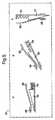
角度を検出するボール弁の代替実施形態は、図5に示すように、ニードル弁による角度検出である。玉軸受の代わりに、ニードル弁ウエッジ33と保持スプリング34が設けられている。ニードル弁は、ライン28の圧力によって流れに押し流されないように重量が設定されており、スプリングは、垂直位置の場合だけウエッジが完全に流れを塞ぐのに適切な伸び長さが設定されている。ボール弁と同様に、角度検出弁の角度が水平位置(D)から垂直位置(F)に変化するにつれ、ニードル33の重量の分解成分でスプリング34が伸び、流入オリフィスの寸法が小さくなる。オリフィスが小さくなることは、ライン28の圧力が角度(E)に比例して高くなることを意味する。 An alternative embodiment of a ball valve that detects the angle is angle detection with a needle valve, as shown in FIG. In place of the ball bearing, a
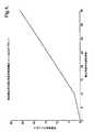
角度検出弁は、正確な角度測定が行えるように、角度検出ライン圧力に基づいて較正することができる。図4は、角度検出弁の角度位置に対する角度検出ライン圧力の結果を示す。 The angle detection valve can be calibrated based on the angle detection line pressure so that an accurate angle measurement can be made. FIG. 4 shows the result of the angle detection line pressure with respect to the angular position of the angle detection valve.
図6は、角度検出弁の角度位置に対する検出ライン圧力上昇および隔室圧力のプロットである。 FIG. 6 is a plot of detected line pressure rise and compartment pressure versus angular position of the angle detection valve.
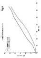
本発明のさらなる実施形態を図7に示す。この図において、図1と同様の参照数字は同様の特徴を指す。非常に急な角度(>50°)で圧力が高くなりすぎないように、隔室圧力上昇を制限することが望ましいことがある。この実施形態において、圧力調整器22が、リストリクター16と角度検出弁19との間の角度検出ライン15に導入される。この圧力調整器で、角度検出ライン15および膨張可能な部材21の最高圧力が制限され、したがって図8に示すように、最高隔室圧力上昇も制限される。 A further embodiment of the invention is shown in FIG. In this figure, reference numerals similar to those in FIG. 1 refer to similar features. It may be desirable to limit the compartment pressure rise so that the pressure does not become too high at very steep angles (> 50 °). In this embodiment, a
図8において、角度検出ライン圧力は、50°で20mmHgに達するまで上昇し、その後、検出弁の角度位置が高まったとしても一定にとどまることがわかる。 In FIG. 8, it can be seen that the angle detection line pressure increases until it reaches 20 mmHg at 50 °, and then remains constant even if the angular position of the detection valve increases.
図9に、本発明のもう1つの実施形態を示す。これは、底付きがおきやすい姿勢角(profiling angle)に達するまで、低い隔室圧力で好ましい治療を維持するために、ある角度に到達してから初めて隔室の膨張を開始することが望ましいことがある場合である。この実施形態では、弁が所定の角度位置内かまたは越えているのかを示す、本質的に2値のスイッチ構成を含む、より簡単な角度検出弁が用いられる。検出する角度位置は、当初装着された際の角度検出弁の向きで決まる。角度検出弁は、いかなる角度位置も決めることができず、単に、弁が所定の角度位置内かまたは越えているかどうかを決めることができるだけである。 FIG. 9 shows another embodiment of the present invention. This is because it is desirable to start the expansion of the compartment only after a certain angle has been reached in order to maintain a favorable treatment at low compartment pressure until a profiling angle is reached. This is the case. In this embodiment, a simpler angle detection valve is used that includes an essentially binary switch configuration that indicates whether the valve is within or beyond a predetermined angular position. The angular position to be detected is determined by the direction of the angle detection valve when initially mounted. The angle detection valve cannot determine any angular position, it can only determine whether the valve is within or beyond a predetermined angular position.
図9に示すように、弁は、中空管41を含むハウジング40からなり、中空管41はハウジングの中間にあるピボット42に「シーソー」形態で装着されている。中空管41の一端の下部には、中空管41が水平位置から一方向の角度位置に傾いた場合、ハウジング41の穴44を密封する密封パッド43がある。中空管41が反対方向の角度位置に傾いた場合、穴44は開放される。他端にあるパッド46はノイズを減衰させる。 As shown in FIG. 9, the valve comprises a
中空管41の中で、玉軸受45によって、シーソー構成に重量と運動量が追加される。たとえば、中空管41が、密封パッド43で穴44が密封されるように傾く場合、玉軸受45によって重量が追加され、高い密封性が確保される。弁が所定の角度位置に傾く場合、玉軸受によって運動量が追加され、確実に弁の状態転換が明白になる。 Within the
シーソー管41の両端のゴムパッドは、玉軸受45がシーソー管端と衝突する際のノイズを減少させる。 The rubber pads at both ends of the
図10は、図1の代替システム内の角度検出弁40を示す。この図では、図1と同様の参照番号は同様の特徴を指す。 FIG. 10 shows an
使用時、空気は、圧縮機2から隔室9および10に供給され、またリストリクター16を通って検出ライン15へ供給され、圧力変換器17および角度検出弁40へ供給される。圧力変換器17は検出ライン15の圧力を検出する。 In use, air is supplied from the
角度検出弁40が所定の角度より低い場合、シーソー管41は、図9bに示すようであり、角度検出ラインの空気は自由に弁を通過し、大気に放出される。したがって検出ライン15には背圧が存在しない。角度検出弁が所定の角度を超えて傾いた場合、シーソー管41は、図9aに示すように、反対方向へ振れる。検出ライン15の空気は、流れが制限され、回路に背圧が生成される。圧力変換器17によって検出される圧力は、2mmhg(通常)未満から8mmHg超に跳ね上がり、制御装置へもたらされる2値信号となる。 When the
圧力制御装置2は、圧力変換器17を用いてこの圧力変化を検出し、次いで、それに従って隔室9および10への圧縮機出力を調整するように作動する。 The
玉軸受45の運動は、密封パッド43の運動とは同一平面内にない。したがって、玉軸受が多少動いても、密封性には最小限の影響しか与えない。制御ソフトウエアは、信号に含まれる残った変動を「抑え込む」。 The movement of the
このシステムを実施した場合、システムは、隔室上に最大160kg載せて、22mmHgと64mmHgとの間で作動する。 When implemented, the system operates between 22 mmHg and 64 mmHg with a maximum of 160 kg on the compartment.
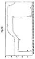
図11、図12および図13に、再度、一連の事象の圧力プロットを示す。各プロットは、異なる目標隔室圧力での一連の事象を示す。点Aで、角度検出弁シーソー管41が、穴44を塞ぐ状態に転換する。検出ライン15の圧力は急速に立ち上がる。検出ライン15の圧力がしばらく安定した後、隔室の目標圧力が、適宜、調整される(点C)。点Dで、隔室9および10が下げられ、角度検出弁シーソー管41が穴から離れて転換し、空気は弁を通過して流れることができる。検出ライン15の圧力は急速に低下する。検出ラインの圧力がしばらく安定した後、隔室の目標圧力は、適宜、調整される(点F)。これにより、マットレス上の患者にとって、システム圧力の「おだやかな変化」が達成される。3つのプロットは、2値スイッチ動作が広い圧力範囲で実現されることを示す。 11, 12 and 13 again show a pressure plot of a series of events. Each plot shows a series of events at different target compartment pressures. At point A, the angle detection
角度検出弁における過去の試みは、結果として「デッドバンド(dead band)」を有する装置をもたらした。デッドバンドはある角度に装置が傾けられた場合に発生し、その結果、装置が、転換すべきときに転換しない、あるいはあまりにも早く状態が転換して2つの状態をいったりきたりするようになる。中空管41内の玉軸受45が、強制的にシーソーを2つの状態のいずれかに素早く転換し、その状態を維持することによって、デッドバンドが除去される。 Past attempts at angle detection valves have resulted in devices having a “dead band”. A dead band occurs when the device is tilted at an angle, so that the device does not switch when it should switch, or it changes state too quickly and can switch between two states. . The
圧力制御装置はまた、弁の角度位置検出直後に、いつ隔室が持ち上げられたかをスクリーン上に画像として示すことができるが、隔室の圧力は、弁の角度位置がしばらく安定した後でのみ調整される。 The pressure controller can also show on the screen as an image when the compartment has been lifted immediately after detecting the angular position of the valve, but the pressure in the compartment is only after the angular position of the valve has stabilized for some time. Adjusted.
1 圧交替式パッド
2 圧縮機
3 供給ライン
4 回転弁
5 空気供給ライン
6 空気供給ライン
7 空気供給ライン
8 空気供給ライン
9 交互に膨張可能な隔室の第1組
10 交互に膨張可能な隔室の第2組
11 流体密封部材
12 放出ライン
13 バルブプレート
14 スプリング手段
15 角度検出ライン
16 リストリクター
17 圧力変換器
19 角度検出弁
20 角度検出弁
21 流体密封部材
30 玉軸受
31 玉軸受
33 ニードル弁ウエッジ
34 保持スプリング
40 角度検出弁
41 中空管
42 ピボット
43 密封パッド
44 穴
45 玉軸受
46 パッドDESCRIPTION OF
Claims (6)
Translated fromJapanese前記角度検出弁が、前記角度検出弁の所定の角度位置あるいは水平位置のいずれかを示す2値スイッチを含み、
前記角度検出弁が、「シーソー」構成で装着された玉軸受を有するハウジングを含み、前記ハウジングが水平位置から所定の角度位置に傾けられると、前記玉軸受が前記ハウジングを通過する空気流を遮断することを特徴とする圧力制御装置。A pressure control device comprising means adapted to sense fluid pressure and to increase or decrease the supply of air pressure when the pressure exceeds a predetermined value, wherein the fluid pressure is detected by the angle detection valve. Brought about by an angle detection valve variable proportional to the angular position,
The angle detection valve includes a binary switch indicating either a predetermined angular position or a horizontal position of the angle detection valve;
The angle detection valve includes a housing having a ball bearing mounted in a “seesaw” configuration, and the ball bearing blocks air flow through the housing when the housing is tilted from a horizontal position to a predetermined angular position. A pressure control device.
Applications Claiming Priority (5)
| Application Number | Priority Date | Filing Date | Title |
|---|---|---|---|
| GB0816485.7 | 2008-09-10 | ||
| GB0816485AGB0816485D0 (en) | 2008-09-10 | 2008-09-10 | Tilt detection and control |
| GB0908605AGB0908605D0 (en) | 2009-05-20 | 2009-05-20 | Tilt detection |
| GB0908605.9 | 2009-05-20 | ||
| PCT/GB2009/051120WO2010029338A2 (en) | 2008-09-10 | 2009-09-03 | Angle detection & control |
Publications (2)
| Publication Number | Publication Date |
|---|---|
| JP2012501710A JP2012501710A (en) | 2012-01-26 |
| JP5323193B2true JP5323193B2 (en) | 2013-10-23 |
Family
ID=42005560
Family Applications (1)
| Application Number | Title | Priority Date | Filing Date |
|---|---|---|---|
| JP2011525627AExpired - Fee RelatedJP5323193B2 (en) | 2008-09-10 | 2009-09-03 | Angle detection and control |
Country Status (9)
| Country | Link |
|---|---|
| US (1) | US8914928B2 (en) |
| EP (1) | EP2350761B1 (en) |
| JP (1) | JP5323193B2 (en) |
| CN (1) | CN102150092B (en) |
| AU (1) | AU2009290715B2 (en) |
| CA (1) | CA2736332C (en) |
| DK (1) | DK2350761T3 (en) |
| ES (1) | ES2735982T3 (en) |
| WO (1) | WO2010029338A2 (en) |
Families Citing this family (6)
| Publication number | Priority date | Publication date | Assignee | Title |
|---|---|---|---|---|
| CA2736332C (en) | 2008-09-10 | 2018-12-04 | Huntleigh Technology Limited | Angle detection & control |
| US10507158B2 (en) | 2016-02-18 | 2019-12-17 | Hill-Rom Services, Inc. | Patient support apparatus having an integrated limb compression device |
| US10856668B2 (en)* | 2017-04-10 | 2020-12-08 | Hill-Rom Services, Inc. | Mattress overlay control system with rotary valves and graphical user interface for percussion and vibration, turn assist and microclimate management |
| US20200037779A1 (en)* | 2018-07-31 | 2020-02-06 | Levy Zur | Area support surface seating system |
| US12036162B1 (en)* | 2021-03-31 | 2024-07-16 | Linet Spol. S R.O. | Mechanical pressure control for mattress for use for medical purposes |
| US12066117B2 (en)* | 2021-05-26 | 2024-08-20 | Waters Technologies Corporation | Check valve having a spherical loading element |
Family Cites Families (40)
| Publication number | Priority date | Publication date | Assignee | Title |
|---|---|---|---|---|
| US4175263A (en) | 1977-04-25 | 1979-11-20 | Triad & Associates, Inc. | Technique for monitoring whether an individual is moving from a particular area |
| US4242672A (en) | 1977-11-09 | 1980-12-30 | Gault Robert L | Patient monitoring system and switch |
| US4195287A (en) | 1977-11-28 | 1980-03-25 | Mathis James C | Fire and absence detection and alarm system for bed occupants |
| US4228426A (en) | 1978-09-29 | 1980-10-14 | Roberts William A | Hospital bed monitor |
| US4539560A (en) | 1982-12-10 | 1985-09-03 | Hill-Rom Company, Inc. | Bed departure detection system |
| NL8301197A (en) | 1983-04-06 | 1984-11-01 | Stichting Revalidatie Inst | LY SUPPORT COMPRISING A COMBINATION OF MULTIPLE PILLOWS, NOT LIGHT OR LEAKS, WITH A SPECIFIC PRESSURE MEASUREMENT AND CONTROL SYSTEM. |
| GB8417611D0 (en) | 1984-07-10 | 1984-08-15 | Talley Medical Equipment Ltd | Control systems for air pads/mattresses |
| US4769584A (en) | 1985-06-18 | 1988-09-06 | Thomas J. Ring | Electronic controller for therapeutic table |
| US5003654A (en) | 1986-09-09 | 1991-04-02 | Kinetic Concepts, Inc. | Method and apparatus for alternating pressure of a low air loss patient support system |
| US4803744A (en) | 1987-05-19 | 1989-02-14 | Hill-Rom Company, Inc. | Inflatable bed |
| US5586348A (en) | 1987-06-24 | 1996-12-24 | Ahlstrom Consumer Products Ltd. | Air mattress and method for adjusting it |
| GB2233551B (en) | 1988-03-14 | 1992-01-08 | Huntleigh Technology Plc | Pressure controller |
| US5802640A (en) | 1992-04-03 | 1998-09-08 | Hill-Rom, Inc. | Patient care system |
| US5189745A (en) | 1989-02-23 | 1993-03-02 | Burke Mobility Products, Inc. | Mattress construction for support structure containing human waste collection system |
| US5144705A (en) | 1989-03-15 | 1992-09-08 | Rogers John E | Seat cushions including a plurality of individual support cells |
| JPH058986Y2 (en)* | 1990-11-27 | 1993-03-05 | ||
| GB2250189B (en) | 1990-11-28 | 1993-11-24 | Nesbit Evans & Co Ltd | Beds |
| US5170364A (en) | 1990-12-06 | 1992-12-08 | Biomechanics Corporation Of America | Feedback system for load bearing surface |
| US5143208A (en) | 1991-02-20 | 1992-09-01 | American Sterilizer Company | Level sensor |
| JPH0646967B2 (en) | 1991-04-25 | 1994-06-22 | フランスベッド株式会社 | Mattress selection device |
| US5325551A (en) | 1992-06-16 | 1994-07-05 | Stryker Corporation | Mattress for retarding development of decubitus ulcers |
| US5526543A (en) | 1992-07-06 | 1996-06-18 | Nova Technologies, Inc. | Method and apparatus for treating or preventing bed sores |
| US5267364A (en) | 1992-08-11 | 1993-12-07 | Kinetic Concepts, Inc. | Therapeutic wave mattress |
| US5611096A (en) | 1994-05-09 | 1997-03-18 | Kinetic Concepts, Inc. | Positional feedback system for medical mattress systems |
| US5458618A (en) | 1994-06-07 | 1995-10-17 | Steinke; James M. | Body motion generating device having high inertial power train |
| US5564520A (en)* | 1994-06-20 | 1996-10-15 | Gt Development Corporation | Pneumatic seat rollover vent valve |
| US5600108A (en) | 1994-08-29 | 1997-02-04 | Bed-Check Corporation | Docking module enclosure including connectors and power switching |
| US5498229A (en) | 1994-09-09 | 1996-03-12 | Air-Shields, Inc. | Infant radiant warmer |
| US6584628B1 (en)* | 1995-08-04 | 2003-07-01 | Hill-Rom Services, Inc. | Hospital bed having a rotational therapy device |
| GB2318392B (en) | 1996-10-17 | 2000-12-20 | Huntleigh Technology Plc | Pressure control system |
| CA2272372C (en)* | 1996-11-18 | 2009-08-04 | Kinetic Concepts, Inc. | Bariatric treatment system and relating methods |
| GB2320892B (en)* | 1996-12-04 | 1999-07-28 | Huntleigh Technology Plc | Alternating pad |
| US5894966A (en)* | 1997-06-26 | 1999-04-20 | Hill-Rom, Inc. | Bariatric bed |
| WO2000003627A2 (en)* | 1998-07-15 | 2000-01-27 | Rostra Precision Controls, Inc. | Electronic control system for a variable support mechanism |
| JP4325116B2 (en) | 2001-01-16 | 2009-09-02 | 富士電機リテイルシステムズ株式会社 | Coin processing equipment |
| CA2477724A1 (en)* | 2002-03-18 | 2003-10-02 | Hill-Rom Services, Inc. | Hospital bed with controlled inflatable portion of patient support |
| US7409735B2 (en)* | 2004-08-16 | 2008-08-12 | Hill-Rom Services, Inc. | Dynamic cellular person support surface |
| US8117701B2 (en)* | 2005-07-08 | 2012-02-21 | Hill-Rom Services, Inc. | Control unit for patient support |
| EP2937070B1 (en) | 2005-07-26 | 2017-02-22 | Hill-Rom Services, Inc. | System and method of controlling an air mattress |
| CA2736332C (en) | 2008-09-10 | 2018-12-04 | Huntleigh Technology Limited | Angle detection & control |
- 2009
- 2009-09-03CACA2736332Apatent/CA2736332C/ennot_activeExpired - Fee Related
- 2009-09-03CNCN200980135568.1Apatent/CN102150092B/ennot_activeExpired - Fee Related
- 2009-09-03JPJP2011525627Apatent/JP5323193B2/ennot_activeExpired - Fee Related
- 2009-09-03ESES09785579Tpatent/ES2735982T3/enactiveActive
- 2009-09-03EPEP09785579.5Apatent/EP2350761B1/enactiveActive
- 2009-09-03USUS13/063,278patent/US8914928B2/enactiveActive
- 2009-09-03DKDK09785579.5Tpatent/DK2350761T3/enactive
- 2009-09-03AUAU2009290715Apatent/AU2009290715B2/enactiveActive
- 2009-09-03WOPCT/GB2009/051120patent/WO2010029338A2/enactiveApplication Filing
Also Published As
| Publication number | Publication date |
|---|---|
| CA2736332C (en) | 2018-12-04 |
| AU2009290715A1 (en) | 2010-03-18 |
| JP2012501710A (en) | 2012-01-26 |
| US8914928B2 (en) | 2014-12-23 |
| EP2350761A2 (en) | 2011-08-03 |
| DK2350761T3 (en) | 2019-07-01 |
| US20110225740A1 (en) | 2011-09-22 |
| AU2009290715B2 (en) | 2016-11-17 |
| CA2736332A1 (en) | 2010-03-18 |
| CN102150092A (en) | 2011-08-10 |
| EP2350761B1 (en) | 2019-03-20 |
| WO2010029338A2 (en) | 2010-03-18 |
| CN102150092B (en) | 2016-01-20 |
| WO2010029338A3 (en) | 2011-08-18 |
| ES2735982T3 (en) | 2019-12-23 |
Similar Documents
| Publication | Publication Date | Title |
|---|---|---|
| JP5323193B2 (en) | Angle detection and control | |
| JP5208732B2 (en) | Control means for pressurized bag in patient support device | |
| JP4245439B2 (en) | Snoring prevention device | |
| JP3115146B2 (en) | Pressure control type expansion pad device | |
| JP5537806B2 (en) | Hospital bed pressure control | |
| US10653575B2 (en) | Patient support apparatus and methods | |
| JP4685330B2 (en) | Inflatable support | |
| AU2002246229B2 (en) | Inflatable support | |
| JP2008545513A6 (en) | Control means for pressurized bag in patient support device | |
| US20070061976A1 (en) | Dynamically inflatable therapeutic support and methods of using the same | |
| EP0556173A1 (en) | Fluid filled flotation mattress | |
| JP2004016521A (en) | Air pressure regulator of airbag | |
| EP3697362A1 (en) | Two-in-one mattress with air mattress and memory foam for patient care | |
| WO2017194037A1 (en) | A mattress with automatic pressure optimization | |
| CN219646013U (en) | Snore relieving system | |
| KR102406794B1 (en) | Mat for bedsore prevention | |
| JPH0754780A (en) | Supply air pressure variable type air pump device | |
| KR20030014225A (en) | Inflatable support |
Legal Events
| Date | Code | Title | Description |
|---|---|---|---|
| A131 | Notification of reasons for refusal | Free format text:JAPANESE INTERMEDIATE CODE: A131 Effective date:20121106 | |
| A521 | Request for written amendment filed | Free format text:JAPANESE INTERMEDIATE CODE: A523 Effective date:20130205 | |
| TRDD | Decision of grant or rejection written | ||
| A01 | Written decision to grant a patent or to grant a registration (utility model) | Free format text:JAPANESE INTERMEDIATE CODE: A01 Effective date:20130625 | |
| A61 | First payment of annual fees (during grant procedure) | Free format text:JAPANESE INTERMEDIATE CODE: A61 Effective date:20130716 | |
| R150 | Certificate of patent or registration of utility model | Ref document number:5323193 Country of ref document:JP Free format text:JAPANESE INTERMEDIATE CODE: R150 Free format text:JAPANESE INTERMEDIATE CODE: R150 | |
| R250 | Receipt of annual fees | Free format text:JAPANESE INTERMEDIATE CODE: R250 | |
| R250 | Receipt of annual fees | Free format text:JAPANESE INTERMEDIATE CODE: R250 | |
| R250 | Receipt of annual fees | Free format text:JAPANESE INTERMEDIATE CODE: R250 | |
| R250 | Receipt of annual fees | Free format text:JAPANESE INTERMEDIATE CODE: R250 | |
| LAPS | Cancellation because of no payment of annual fees |