JP5317821B2 - Antenna device - Google Patents
Antenna deviceDownload PDFInfo
- Publication number
- JP5317821B2 JP5317821B2JP2009116968AJP2009116968AJP5317821B2JP 5317821 B2JP5317821 B2JP 5317821B2JP 2009116968 AJP2009116968 AJP 2009116968AJP 2009116968 AJP2009116968 AJP 2009116968AJP 5317821 B2JP5317821 B2JP 5317821B2
- Authority
- JP
- Japan
- Prior art keywords
- phase
- excitation
- antenna
- beams
- antenna elements
- Prior art date
- Legal status (The legal status is an assumption and is not a legal conclusion. Google has not performed a legal analysis and makes no representation as to the accuracy of the status listed.)
- Expired - Fee Related
Links
Images


Landscapes
- Aerials With Secondary Devices (AREA)
- Variable-Direction Aerials And Aerial Arrays (AREA)
Abstract
Description
Translated fromJapaneseこの発明は、例えば人工衛星等に設けられ、マルチビームを出力するアンテナ装置に関する。 The present invention relates to an antenna device that is provided in, for example, an artificial satellite and outputs a multi-beam.
例えば、特許文献1に示すような従来のアンテナ装置では、複数のビーム形成回路は、それぞれ複数のビームに対してそれぞれ独立に励振振幅及び励振位相を調整する手段を有しており、異なる方向へ向けた複数のビームを形成可能となっている。そして、複数のビーム形成回路からの信号が、複数の増幅器を介して、フィードアレーの複数のアンテナ素子へ送られ、複数のアンテナ素子からマルチビームが放射される。なお、アンテナ素子及び増幅器は、その全てのビームについて共通化されており、全てのビームについて合成された信号を受ける。 For example, in the conventional antenna device as shown in
また、例えば、特許文献2に示すような従来のアンテナ装置では、基本構成は特許文献1に示すような従来のアンテナ装置と同様であるが、各アンテナ素子の励振振幅が等振幅となるように構成されている。 Further, for example, in the conventional antenna device as shown in
特許文献1に示すような従来のアンテナ装置では、マルチビームを同時に形成する場合、各アンテナ素子に与える励振振幅の分布はビーム毎に異なる。具体的に、ビーム方向と幾何光学的に概ね対応する位置に存在するアンテナ素子の励振振幅値は、比較的大きく、その幾何光学的に対応する位置から離れるに従って、アンテナ素子の励振振幅値が小さくなる。 In the conventional antenna apparatus as shown in
ここで、アンテナ素子及び増幅器は、全てのビームについて共通化されているため、これらの励振振幅分布の全てを足し合わせた分布が、最終的な各アンテナ素子の放射電力の分布、即ち増幅器の送信電力分布となる。これにより、マルチビームを密に配置した場合には、各増幅器の送信電力がフィードアレーの開口中心付近で比較的大きく、開口端部側へ離れるに従って小さくなる分布となる。このため、全ての増幅器の最大出力を同一とした場合には、フィードアレーの開口端部の増幅器の電源効率が著しく低下するという課題があった。 Here, since the antenna element and the amplifier are common to all the beams, the distribution of all these excitation amplitude distributions is the final distribution of the radiated power of each antenna element, that is, transmission of the amplifier. Power distribution. As a result, when multiple beams are densely arranged, the transmission power of each amplifier is relatively large near the center of the opening of the feed array, and becomes a distribution that becomes smaller as the distance to the opening end portion increases. For this reason, when the maximum outputs of all the amplifiers are made the same, there is a problem that the power supply efficiency of the amplifiers at the opening end portions of the feed array is remarkably lowered.
なお、この課題を回避するために送信電力分布に従い最大出力の異なる増幅器を複数種類用いることも考えられるが、ビーム間の送信電力制御に対応できなかったり、アンテナ装置の製造コストが増加したりする等の別の問題が生じる。 In order to avoid this problem, it is conceivable to use a plurality of types of amplifiers having different maximum outputs according to the transmission power distribution. However, it is not possible to cope with transmission power control between beams, or the manufacturing cost of the antenna device increases. Another problem arises.
また、特許文献2に示すような従来のアンテナ装置では、各アンテナ素子の励振振幅値が等振幅とされており、マルチビーム形成時のトータルの送信電力分布も等振幅分布となるので、上記した増幅器の電源効率低下の問題は発生しない。しかしながら、励振振幅分布を等振幅にしたことにより、アンテナ利得が低下するという課題があった。 Further, in the conventional antenna device as shown in
この発明は、上記のような課題を解決するためになされたものであり、単一種類の複数の増幅器を用いた場合に、各アンテナ素子の励振振幅分布を等振幅としないときにも、増幅器の電源効率を向上させることができるアンテナ装置を得ることを第1の目的とする。 The present invention has been made in order to solve the above-described problems. When a plurality of single-type amplifiers are used, the amplifier amplitude distribution of each antenna element is not equal. It is a first object of the present invention to obtain an antenna device that can improve the power supply efficiency.
また、この発明は、増幅器の電源効率を向上させるために各増幅器の送信電力分布を等振幅とした場合に、アンテナ利得を向上させることができるアンテナ装置を得ることを第2の目的とする。 A second object of the present invention is to obtain an antenna device capable of improving the antenna gain when the transmission power distribution of each amplifier is made equal in amplitude in order to improve the power supply efficiency of the amplifier.
この発明に係るアンテナ装置は、反射鏡導体と、前記反射鏡導体の焦点から離れた位置に配置され、複数のアンテナ素子からなるフィードアレーと、前記複数のアンテナ素子に接続された複数の増幅器と、前記複数の増幅器を介して前記複数のアンテナ素子に接続され、前記複数のアンテナ素子への励振振幅及び励振位相をそれぞれ調整可能であり、励振振幅及び励振位相を調整することにより互いに異なるビーム幅の複数のビームを前記複数のアンテナ素子から放射させるビーム形成ユニットとを備え、前記ビーム形成ユニットの振幅調整量及び移相量は、所定のカバレッジエリアの中央部領域へ向けて前記複数のビームのうちビーム幅の狭い狭ビームを放射するとともに、前記カバレッジエリアの端部領域へ向けて前記複数のビームのうちビーム幅の広い広ビームを放射するように設定され、かつ前記広ビームの送信電力を前記狭ビームの送信電力よりも高くすることで、前記複数のビームの全ての等価等方放射電力が同一となるように設定されているものである。An antenna device according to the present invention includes a reflecting mirror conductor, a feed array that is disposed at a position away from a focal point of the reflecting mirror conductor, and includes a plurality of antenna elements, and a plurality of amplifiers connected to the plurality of antenna elements. , Connected to the plurality of antenna elements via the plurality of amplifiers, the excitation amplitude and the excitation phase to the plurality of antenna elements can be adjusted respectively, and the beam widths different from each other by adjusting the excitation amplitude and the excitation phase A beam forming unit that radiates the plurality of beams from the plurality of antenna elements, and the amount of amplitude adjustment and the amount of phase shift of the beam forming unit are adjusted to a central area of a predetermined coverage area. Among them, a narrow beam having a narrow beam width is emitted, and the plurality of beams are directed toward an end region of the coverage area. Set a wide wide beam beamwidth to emit, andthe is made higher than the transmission power of the narrow beam the transmission power of the broad beam, all equivalent isotropic radiated power of the plurality of beams is the same It is set to be.
この発明に係るアンテナ装置によれば、前記ビーム形成ユニットの振幅調整量及び移相量は、前記複数のビームのうちビーム幅の狭い狭ビームを所定のカバレッジエリアの中央部領域へ向けて前記複数のアンテナ素子から放射させるとともに、前記複数のビームのうちビーム幅の広い広ビームを前記カバレッジエリアの端部領域へ向けて前記複数のアンテナ素子から放射させるように設定され、かつ前記複数のビームの全ての等価等方放射電力が同一となるように設定されているので、単一種類の複数の増幅器を用いた場合に、各アンテナ素子の励振振幅分布を等振幅としないときにも、増幅器の電源効率を向上させることができる。 According to the antenna device of the present invention, the amplitude adjustment amount and the phase shift amount of the beam forming unit are set such that the narrow beam having a narrow beam width among the plurality of beams is directed toward a central region of a predetermined coverage area. Of the plurality of beams, and a wide beam having a wide beam width is set to be radiated from the plurality of antenna elements toward an end region of the coverage area, and Since all equivalent isotropic radiated powers are set to be the same, when a plurality of single-type amplifiers are used, even when the excitation amplitude distribution of each antenna element is not equal, Power supply efficiency can be improved.
以下、この発明を実施するための形態について、図面を参照して説明する。
実施の形態1.
図1は、この発明の実施の形態1によるアンテナ装置の概略構成を示す斜視図である。
図1において、実施の形態1のアンテナ装置は、マルチビームを放射可能な離焦点アレー給電反射鏡形式のマルチビームアンテナである。また、実施の形態1のアンテナ装置は、導体からなる反射鏡導体1、フィードアレー2、及びビーム形成ユニット3を有している。反射鏡導体1は、例えば、回転放物面形状の反射鏡である。また、反射鏡導体1の焦点は、図1のF点に設定されている。Hereinafter, embodiments for carrying out the present invention will be described with reference to the drawings.
1 is a perspective view showing a schematic configuration of an antenna apparatus according to
In FIG. 1, the antenna apparatus of
図2は、図1のフィードアレー2及びビーム形成ユニット3を示す構成図である。図2では、アンテナ素子数がMであり、ビーム数がNである場合の機能ブロック図を示している。図2において、フィードアレー2は、複数のアンテナ素子4−1〜4−Mによって構成されている。なお、例えば4−mと表した場合には、m番目のアンテナ素子4を表す。 FIG. 2 is a block diagram showing the
ビーム形成ユニット3は、複数の増幅器5−1〜5−Mと、複数の合成回路6−1〜6−Mと、複数のビーム形成回路7−1〜7−Nと、位相制御部としての位相振幅制御回路8とを有している。増幅器5−1〜5−Mは、それぞれアンテナ素子4−1〜4−Mに接続されている。また、増幅器5−1〜5−Mは、アンテナ素子4−1〜4−Mへの信号を増幅する。合成回路6−1〜6−Mは、それぞれ増幅器5−1〜5−Mに接続されている。 The
なお、増幅器5−1〜5−Mの個数、及び合成回路6−1〜6−Mの個数は、それぞれアンテナ素子数Mに対応した個数である。また、例えば5−mと表した場合には、m番目のアンテナ素子4に対応する増幅器5を表し、例えば6−mと表した場合には、m番目のアンテナ素子4に対応する合成回路6を表す。 The number of amplifiers 5-1 to 5-M and the number of combining circuits 6-1 to 6-M are numbers corresponding to the number M of antenna elements. Further, for example, when expressed as 5-m, it represents the
ビーム形成回路7−1〜7−Nは、入力端子9−1〜9−Nと、分配回路10−1〜10−Nと、複数の移相器11−1−1〜11−N−Mと、複数の減衰器12−1−1〜12−N−Mとを有している。ビーム形成回路7−1〜7−Nの個数、入力端子9−1〜9−Nの個数、及び分配回路10−1〜10−Nの個数は、それぞれビーム数Nに対応した個数である。例えば7−nと表した場合には、n番目のビームに対応するビーム形成回路7を表し、例えば9−nと表した場合には、n番目のビームに対応する入力端子9を表し、例えば10−nと表した場合には、n番目のビームに対応する分配回路10を表す。 The beam forming circuits 7-1 to 7-N include input terminals 9-1 to 9-N, distribution circuits 10-1 to 10-N, and a plurality of phase shifters 11-1-1-1 to 11-NM. And a plurality of attenuators 12-1-1 to 12 -N-M. The number of beam forming circuits 7-1 to 7-N, the number of input terminals 9-1 to 9-N, and the number of distribution circuits 10-1 to 10-N are numbers corresponding to the number of beams N, respectively. For example, 7-n represents the
また、移相器11−1−1〜11−N−Mの個数、及び減衰器12−1−1〜12−N−Mの個数は、それぞれビーム数Nとアンテナ素子数Mとの積に対応した個数である。例えば11−n−mと表した場合には、n番目のビームに対応し、かつm番目のアンテナ素子4−mに対応する移相器11を表す。また、例えば12−n−mと表した場合には、n番目のビームに対応し、かつm番目のアンテナ素子4−mに対応する減衰器12を表す。 The number of phase shifters 11-1-1 to 11-NM and the number of attenuators 12-1-1-1 to 12-NM are the products of the number of beams N and the number of antenna elements M, respectively. The corresponding number. For example, when expressed as 11-nm, it represents the
なお、図2では、分配回路10−1〜10−Nのうち分配回路10−1のみを示し、移相器11−1−1〜11−N−Mのうち移相器11−1−1〜11−1−Mのみを示し、減衰器12−1−1〜12−N−Mのうち減衰器12−1−1〜12−1−Mのみを示す。 2 shows only the distribution circuit 10-1 among the distribution circuits 10-1 to 10-N, and the phase shifter 11-1-1 among the phase shifters 11-1-1 to 11-N-M. Only 11-11-M are shown, and only the attenuators 12-1-1-1 to 12-1-M among the attenuators 12-1-1-1 to 12-NM are shown.
入力端子9−1〜9−Nには、それぞれ通信装置(図示せず)から、ビーム数Nに対応した数の信号が入力される。入力端子9−1〜9−Nに入力された信号は、分配回路10−1〜10−Nによって、移相器11−1−1〜11−N−Mへ分配される。移相器11−1−1〜11−N−Mは、入力端子9−1〜9−Nから受けた信号の位相を調整可能になっている。即ち、移相器11−1−1〜11−N−Mは、複数のアンテナ素子4−1〜4−Mのそれぞれの励振位相を調整可能になっている。 A number of signals corresponding to the number of beams N are input to the input terminals 9-1 to 9-N, respectively, from a communication device (not shown). Signals input to the input terminals 9-1 to 9-N are distributed to the phase shifters 11-1-1-1 to 11-N-M by the distribution circuits 10-1 to 10-N. The phase shifters 11-1-1 to 11-NM can adjust the phases of signals received from the input terminals 9-1 to 9-N. That is, the phase shifters 11-1-1 to 11-NM can adjust the excitation phases of the plurality of antenna elements 4-1 to 4-M.
減衰器12−1−1〜12−N−Mは、それぞれ移相器11−1−1〜11−N−Mに直列に接続されている。また、減衰器12−1−1〜12−N−Mは、移相器11−1−1〜11−N−Mから受けた信号の振幅を調整可能になっている。即ち、減衰器12−1−1〜12−N−Mは、複数のアンテナ素子4−1〜4−Mのそれぞれの励振振幅を調整可能になっている。 The attenuators 12-1-1 to 12-NM are connected in series to the phase shifters 11-1-1 to 11-NM, respectively. In addition, the attenuators 12-1-1 to 12-NM can adjust the amplitudes of the signals received from the phase shifters 11-1-1 to 11-NM. That is, the attenuators 12-1-1-1 to 12-NM can adjust the excitation amplitudes of the plurality of antenna elements 4-1 to 4-M.
さらに、減衰器12−1−1〜12−N−Mは、それぞれ合成回路6−1〜6−Mに接続されている。合成回路6−1〜6−Mは、ビーム形成回路7−1〜7−Nのそれぞれからの信号を合成(合波)し、その合成した信号を増幅器5−1〜5−Mへ送る。従って、アンテナ素子4−1〜4−M及び増幅器5−1〜5−Mは、合成回路6−1〜6−Mから、全てのビームについての合成された信号を受ける。即ち、アンテナ素子4−1〜4−M及び増幅器5−1〜5−Mは、その全てのビームについて共通化されている。 Further, the attenuators 12-1-1-1 to 12-NM are connected to the synthesis circuits 6-1 to 6-M, respectively. The synthesis circuits 6-1 to 6-M synthesize (combine) the signals from the beam forming circuits 7-1 to 7-N, and send the synthesized signals to the amplifiers 5-1 to 5-M. Accordingly, the antenna elements 4-1 to 4-M and the amplifiers 5-1 to 5-M receive the combined signals for all the beams from the combining circuits 6-1 to 6-M. That is, the antenna elements 4-1 to 4-M and the amplifiers 5-1 to 5-M are shared by all the beams.
ここで、移相器11−1−1〜11−N−Mのそれぞれの移相量と、減衰器12−1−1〜12−N−Mのそれぞれの減衰量とは、位相振幅制御回路8によって制御される。ここで、図2では、位相振幅制御回路8が移相器11−1−M及び減衰器12−1−Mにのみ接続された構成を示すが、位相振幅制御回路8は、他の移相器11及び減衰器12にも接続されている。位相振幅制御回路8は、移相器11−1−1〜11−N−Mの移相量と減衰器12−1−1〜12−N−Mの減衰量とを設定することにより、互いに異なるビーム幅の複数のビーム、即ちマルチビームをアンテナ素子4−1〜4−Mから放射させる。 Here, each phase shift amount of the phase shifters 11-1-1 to 11-NM and each attenuation amount of the attenuators 12-1-1 to 12-NM are phase amplitude control circuits. 8 is controlled. Here, FIG. 2 shows a configuration in which the phase amplitude control circuit 8 is connected only to the phase shifter 11-1-M and the attenuator 12-1-M, but the phase amplitude control circuit 8 has other phase shifts.
次に、動作について説明する。例えば、複数のビームのうち1番目のビームに対応する信号は、ビーム形成回路7−1の入力端子9−1に入力され、分配回路10−1によりM個に分配される。そして、分配された信号は、所望の方向にビームを形成するように、減衰器12−1−1〜12−1−Mにより振幅値を調整され、その後に移相器11−1−1〜9−1−Mにより位相値を調整されてビーム形成回路7−1から出力される。これと同様に、2番目〜N番目のビームに対応する信号も、減衰器12−2−1〜12−N−M及び移相器11−2−1〜11−N−Mを介して、ビーム形成回路7−2〜7−Nから出力される。 Next, the operation will be described. For example, a signal corresponding to the first beam among the plurality of beams is input to the input terminal 9-1 of the beam forming circuit 7-1 and distributed to M by the distribution circuit 10-1. The distributed signal is adjusted in amplitude value by the attenuators 12-1-1-1 to 12-1-M so as to form a beam in a desired direction, and then the phase shifters 11-1-1-1. The phase value is adjusted by 9-1-M and output from the beam forming circuit 7-1. Similarly, the signals corresponding to the second to Nth beams are also passed through the attenuators 12-2-1 to 12-NM and the phase shifters 11-2-1 to 11-NM. Output from the beam forming circuits 7-2 to 7-N.
このビーム形成回路7−1〜7−Nから出力された信号は、合成回路6−1〜6−Mによって、対応するアンテナ素子4毎に合成される。そして、合成回路6−1〜6−Mからの信号は、増幅器5−1〜5−Mを介して、アンテナ素子4−1〜4−Mに伝わる。これにより、アンテナ素子4−1〜4−Mが信号によって励振されて、アンテナ素子4−1〜4−MからN本のビーム、即ちマルチビームが反射鏡導体1に向けて放射される。 The signals output from the beam forming circuits 7-1 to 7-N are combined for each
次に、マルチビーム配置と、それを形成するための各アンテナ素子の励振振幅分布の関係について従来のアンテナ装置と対比して説明する。なお、従来のアンテナ装置の基本的な構成は、図1,2に示すアンテナ装置の構成と同様のものとする。図3は、従来のアンテナ装置のマルチビーム配置を説明するための説明図である。図3において、100はマルチビームを配置するカバレッジエリアを示し、101はカバレッジエリア100に配置する個々のビームを示す。 Next, the relationship between the multi-beam arrangement and the excitation amplitude distribution of each antenna element for forming the multi-beam arrangement will be described in comparison with a conventional antenna apparatus. The basic configuration of the conventional antenna apparatus is the same as that of the antenna apparatus shown in FIGS. FIG. 3 is an explanatory diagram for explaining a multi-beam arrangement of a conventional antenna device. In FIG. 3,
また、図4は、図3のマルチビーム配置に対応する各アンテナ素子の励振振幅値の分布を説明するための説明図である。図4において、102−1〜102−Nは、各ビームを形成するために各アンテナ素子の励振振幅値の分布パターンを示したものである。例えば、102−nと表した場合にはn番目のビームを形成するための励振振幅値の分布パターンを表している。 FIG. 4 is an explanatory diagram for explaining the distribution of excitation amplitude values of the antenna elements corresponding to the multi-beam arrangement of FIG. In FIG. 4, reference numerals 102-1 to 102-N denote distribution patterns of excitation amplitude values of the respective antenna elements in order to form the respective beams. For example, 102-n represents a distribution pattern of excitation amplitude values for forming the n-th beam.
ここで、図4では、各アンテナ素子の励振振幅値をビーム毎に示したが、アンテナ素子及び増幅器は、全てのビームについて共通化されているので、最終的な各アンテナ素子からの放射電力の分布、即ち各増幅器の送信電力分布は、図4における励振振幅値102−1〜102−Nを足し合わせたものになる。 Here, in FIG. 4, the excitation amplitude value of each antenna element is shown for each beam. However, since the antenna element and the amplifier are shared by all beams, the final radiation power from each antenna element is shown. The distribution, that is, the transmission power distribution of each amplifier, is obtained by adding the excitation amplitude values 102-1 to 102-N in FIG.
図5は、従来のアンテナ装置の各増幅器の送信電力分布を説明するための説明図である。図5において、103は各増幅器の送信電力分布である。送信電力分布103は、フィードアレーの開口中心付近の送信電力が大きく、フィードアレーの開口端部付近での送信電力が小さくなる分布となる。つまり、図5によれば、従来のアンテナ装置では、単一種類の増幅器を用いた場合に、フィードアレーの開口端部付近の増幅器の電源効率が開口中心部分よりも大きく低下していることがわかる。 FIG. 5 is an explanatory diagram for explaining the transmission power distribution of each amplifier of the conventional antenna apparatus. In FIG. 5,
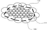
図6は、実施の形態1のアンテナ装置のマルチビーム配置を説明するための説明図である。図6において、111はカバレッジエリア100の中央部領域に配置されたビーム幅の狭いビームを示し、112はカバレッジエリア100の端部領域に配置されたビーム幅の広いビームを示す。 FIG. 6 is an explanatory diagram for explaining a multi-beam arrangement of the antenna device according to the first embodiment. In FIG. 6,
ここで、各移相器11の移相量、及び各減衰器12の減衰量(振幅調整量)は、狭ビーム111をカバレッジエリア100の中央部領域へ向けて各アンテナ素子4から放射させるとともに、広ビーム112をカバレッジエリア100の端部領域へ向けて各アンテナ素子4から放射させるように、振幅位相制御回路8によって設定されている。また、各移相器11の移相量、及び各減衰器12の減衰量は、複数のビームの全ての等価等方放射電力が同一となるように、振幅位相制御回路8によって設定されている。 Here, the phase shift amount of each
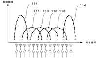
次に、図6に示すようなマルチビームを形成し、かつ全てのビームに対してEIRP(Equivalent Isotropically Radiated Power:等価等方放射電力)を同一にするために、各アンテナ素子4に与える励振振幅値は、図7に示すようになる。 Next, in order to form a multi-beam as shown in FIG. 6 and to make all the beams have the same EIRP (Equivalent Isotropically Radiated Power), the excitation amplitude given to each
図7において、113は狭ビーム111を形成するための励振振幅分布であり、114は広ビーム112を形成するための励振振幅分布である。広ビーム112は狭ビーム111に比べるとビーム幅が狭いので、広ビーム112のアンテナ利得は狭ビーム111に比べると低くなる。このため、全てのビームに対してEIRPを同一にするためには、広ビーム112の送信電力を高くし、狭ビーム111の送信電力を低くする必要がある。また、広ビーム112を形成するための励振振幅分布は、狭ビーム111を形成するための励振振幅分布と比べると振幅値が大きいアンテナ素子4が少なくなる。 In FIG. 7, 113 is an excitation amplitude distribution for forming the
以上のことから、実施の形態1のアンテナ装置では、各アンテナ素子4−1〜4−Mに与える励振振幅分布をビーム毎に示すと図7のようになる。即ち、フィードアレー2の端部のアンテナ素子4の励振振幅値がフィードアレー2の中央部のアンテナ素子4に比べると大きくなる。 From the above, in the antenna device of the first embodiment, the excitation amplitude distribution given to each antenna element 4-1 to 4-M is shown for each beam as shown in FIG. That is, the excitation amplitude value of the
ここで、図7では、ビーム毎に各アンテナ素子4の励振振幅値を示したが、アンテナ素子4及び増幅器5は、全てのビームについて共通化されているので、最終的な各アンテナ素子4からの放射電力、即ち各増幅器5の送信電力は、図7に示した励振振幅値を足し合わせたものになる。 Here, in FIG. 7, the excitation amplitude value of each
図8は、実施の形態1のアンテナ装置の各増幅器5の送信電力分布を説明するための説明図である。図8において、103は従来のアンテナ装置での送信電力分布(図5の分布)を示し、115は実施の形態1のアンテナ装置での送信電力分布を示す。この図8に示すように、実施の形態1のアンテナ装置の送信電力は、従来のアンテナ装置と比べると均一な分布となることがわかる。 FIG. 8 is an explanatory diagram for explaining the transmission power distribution of each
上記のような実施の形態1のアンテナ装置によれば、各移相器11の移相量、及び各減衰器12の減衰量(振幅調整量)は、狭ビーム111をカバレッジエリア100の中央部領域へ向けて各アンテナ素子4から放射させるとともに、広ビーム112をカバレッジエリア100の端部領域へ向けて各アンテナ素子4から放射させるように設定されている。また、各移相器11の移相量、及び各減衰器12の減衰量は、複数のビームの全ての等価等方放射電力が同一となるように設定されている。この構成により、単一種類の複数の増幅器5を用いた場合に、各アンテナ素子4の励振振幅分布を等振幅としないときにも、増幅器5の電源効率を向上させることができる。 According to the antenna device of the first embodiment as described above, the amount of phase shift of each
実施の形態2.
この発明の実施の形態2のアンテナ装置では、カバレッジエリアのうちユーザ密度が小さく、通信トラフィックが低い領域に、広ビーム112が配置されている。また、実施の形態2のアンテナ装置では、カバレッジエリアのうちユーザ密度が大きく、通信トラフィックが高い領域に、狭ビーム111が配置されている。即ち、実施の形態2の各移相器11の移相量、及び各減衰器12の減衰量は、広ビーム112をカバレッジエリアのうちユーザ密度が小さく、通信トラフィックが低い領域へ向けて各アンテナ素子4から放射させるように設定されている。
In the antenna apparatus according to the second embodiment of the present invention,
図9は、この発明の実施の形態2によるマルチビーム配置の一例を説明するための説明図である。図9に示すように、例えば、日本列島のように周囲を海で囲まれている地域をカバレッジエリアとする場合には、広ビーム112を海上領域に配置し、狭ビーム111を地上領域に配置する。海上領域は、地上領域に比べるとユーザ密度が小さく通信トラフィックが低い領域である。他の構成及び動作は、実施の形態1と同様である。 FIG. 9 is an explanatory diagram for explaining an example of the multi-beam arrangement according to the second embodiment of the present invention. As shown in FIG. 9, for example, when the area surrounded by the sea such as the Japanese archipelago is used as the coverage area, the
上記のような実施の形態2のアンテナ装置によれば、カバレッジエリアのうちユーザ密度が小さく、かつ通信トラフィックが低い海上領域に広ビーム112が配置されている。この構成によって、より効率的なビーム配置を実現できる。即ち、実施の形態2のアンテナ装置は、実施の形態1のアンテナ装置と同様の効果を得ることができるとともに、より効率的なビーム配置を実現することができる。 According to the antenna apparatus of the second embodiment as described above, the
実施の形態3.
実施の形態1,2では、各増幅器5の励振振幅分布を等振幅としない場合のアンテナ装置について説明した。これに対して、実施の形態3では、各増幅器5の電源効率を向上させるために各増幅器5の送信電力分布を等振幅とした場合のアンテナ装置について説明する。
In the first and second embodiments, the antenna device in the case where the excitation amplitude distribution of each
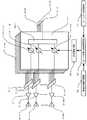
図10は、この発明の実施の形態3によるアンテナ装置の一部を示す構成図である。図10において、実施の形態3のアンテナ装置の構成は、実施の形態1のアンテナ装置における減衰器12−1−1〜12−N−Mが省略された構成となっている。実施の形態3のアンテナ装置は、実施の形態1のアンテナ装置における位相振幅制御回路8に代えて、位相制御回路38を位相制御部として有している。位相制御回路38は、複数の移相器11−1−1〜11−N−Mのそれぞれの移相量を制御する。他の構成は、実施の形態1のアンテナ装置と同様である。 FIG. 10 is a block diagram showing a part of an antenna apparatus according to
次に、図11は、図10のアンテナ装置の諸元を説明するための説明図である。図11において、Dは、反射鏡導体1の開口径である。Rは、焦点Fから反射鏡導体1までの距離である。Aは、フィードアレー2の開口半径である。zdは、焦点Fからフィードアレー2の開口までの離焦点距離である。Xa・Ya・Zaは、反射鏡導体1の位置を示すための座標系定義を示しており、ここではアンテナ座標系と称する。Xf・Yf・Zfは、フィードアレー2を構成する各アンテナ素子の位置を示すための座標系定義を示しており、ここではフィード座標系と称する。 Next, FIG. 11 is explanatory drawing for demonstrating the item of the antenna apparatus of FIG. In FIG. 11, D is the opening diameter of the reflecting
ここで、図10に示すように、実施の形態3のアンテナ装置では、実施の形態1,2のアンテナ装置における減衰器12−1−1〜12−N−Mが省略されており、各アンテナ素子4の励振振幅は全てのビームに対して等振幅となっている。このときの実施の形態3のアンテナ装置によるEIRPは、近似的に、次の式(1)で求められ、アンテナ利得(=G)は次の式(2)で求められる。 Here, as shown in FIG. 10, in the antenna device of the third embodiment, the attenuators 12-1-1 to 12 -NM in the antenna device of the first and second embodiments are omitted, and each antenna The excitation amplitude of the

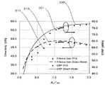
次に、図12は、図10のアンテナ装置のEIRP及びアンテナ利得を示すグラフである。図12では、開口径Dを121.7λとし、焦点Fと反射鏡導体1との間の距離Rを115.7λとし、各増幅器5の送信電力を10Wとし、ビーム数を10とした場合の式(1)及び式(2)に基づくEIRP及びアンテナ利得を示す。また、図12は、フィードアレー2の離焦点距離zdを18.3λで固定値とし、フィードアレー2の開口半径Aを変化させたときのアンテナ装置のEIRP及びアンテナ利得の変化を示している。 Next, FIG. 12 is a graph showing EIRP and antenna gain of the antenna apparatus of FIG. In FIG. 12, the aperture diameter D is 121.7λ, the distance R between the focal point F and the
図12において、300は式(1)により計算したEIRPを示し、301は高精度な解析法である物理光学法により計算したEIRPを示している。また、310は式(2)により計算したアンテナ利得を示し、311は物理光学法により計算したアンテナ利得を示している。また、図12の横軸はフィードアレー2の開口半径Aの変化を式(4)で与えられるωに対する比を示しており、図12の縦軸はEIRP及びアンテナ利得を示している。 In FIG. 12, 300 indicates the EIRP calculated by the equation (1), and 301 indicates the EIRP calculated by the physical optical method which is a highly accurate analysis method.
図12によれば、式(1)及び式(2)による計算結果は、高精度な解析法である物理光学法による計算結果と良く対応しており、実施の形態3のアンテナ装置の性能を良く表現していることがわかる。このことから、式(1)及び式(2)に基づいて、実施の形態3のアンテナ装置の性能を分析すると、フィードアレー2の離焦点距離zdを一定とした場合に、EIRPは、フィードアレー2の開口半径Aにより単調増加し、ある一定値に収束することがわかる。 According to FIG. 12, the calculation results by the equations (1) and (2) correspond well with the calculation results by the physical optical method, which is a highly accurate analysis method, and the performance of the antenna device of the third embodiment is improved. You can see that it expresses well. From this, when analyzing the performance of the antenna device of the third embodiment based on the equations (1) and (2), when the defocus distance zd of the
そして、図12に示すように、アンテナ利得は、フィードアレー2の開口半径Aに対してA=1.12ωとなる場合に極大値を有することがわかる。従って、実施の形態3では、フィードアレー2の開口半径を1.12ωとする。これにより、効率的なアンテナ装置を得ることができる。そして、式(3)から式(5)に基づいて変数ωを展開すると、アンテナ利得が極大値となるフィードアレー2の開口半径は、次の式(7)となる。 As shown in FIG. 12, the antenna gain has a maximum value when A = 1.12ω with respect to the opening radius A of the
上記のような実施の形態3のアンテナ装置では、各アンテナ素子4の励振振幅を全てのビームに対して等振幅としており、その結果として各増幅器5の送信電力も等振幅となるので、増幅器5の電源効率を向上させることができる。 In the antenna device according to the third embodiment as described above, the excitation amplitude of each
また、フィードアレー2の開口半径Aが式(7)で与えられる寸法となるように設定されている。この構成により、アンテナ利得を極大とすることができ、アンテナ利得を向上させることができる。従って、効率的なアンテナ装置を得ることができる。 Further, the opening radius A of the
実施の形態4.
実施の形態3のアンテナ装置では、フィードアレー2の離焦点距離zdを固定し、フィードアレー2の開口半径Aを変化させた場合のEIRP及びアンテナ利得について説明した。これに対して、実施の形態4のアンテナ装置では、フィードアレー2の開口半径Aを固定し、フィードアレー2の離焦点距離zdを変化させた場合のEIRP及びアンテナ利得について説明する。なお、実施の形態4のアンテナ装置の構成は、フィードアレー2の開口半径Aとフィードアレー2の離焦点距離zdとの関係を除いて、実施の形態3のアンテナ装置の構成と同様である。
In the antenna device according to the third embodiment, the EIRP and the antenna gain when the defocus distance zd of the
図13は、この発明の実施の形態4のアンテナ装置のEIRP及びアンテナ利得を示すグラフである。図13では、例えばフィードアレー2の開口半径A=7.5λで固定し、フィードアレー2の離焦点距離zdを変化させたときのアンテナ装置のEIRP及びアンテナ利得の変化を示している。図13の横軸は、フィードアレー2の離焦点距離zdの変化を焦点Fと反射鏡導体1との間の距離Rに対する比を示しており、図13の縦軸はEIRP及びアンテナ利得を示している。なお、図13に示す特性の他の条件は、実施の形態3の図12の場合と同様である。 FIG. 13 is a graph showing the EIRP and antenna gain of the antenna device according to the fourth embodiment of the present invention. FIG. 13 shows changes in the EIRP and antenna gain of the antenna device when the
図13において、400は式(1)により計算したEIRPを示し、401は高精度な解析法である物理光学法により計算したEIRPを示している。また、410は式(2)により計算したアンテナ利得を示し、411は物理光学法により計算したアンテナ利得を示している。また、図13の横軸はフィードアレー2の開口半径Aの変化を式(4)で与えられるωに対する比を示しており、図13の縦軸はEIRP及びアンテナ利得を示している。 In FIG. 13, 400 indicates the EIRP calculated by the equation (1), and 401 indicates the EIRP calculated by the physical optical method, which is a highly accurate analysis method.
図13によれば、先の式(1)及び式(2)による計算結果は、実施の形態3の場合と同様に、物理光学法による計算結果と良く対応しており、実施の形態4のアンテナ装置の性能を良く表現していることがわかる。このことから、式(1)及び式(2)に基づいて、実施の形態4のアンテナ装置の性能を分析すると、フィードアレー2の開口半径Aを一定とした場合に、実施の形態3と同様に、EIRP及びアンテナ利得はA=1.12ωとなる場合に極大値を有することがわかる。 According to FIG. 13, the calculation results by the previous equations (1) and (2) correspond well to the calculation results by the physical optical method as in the third embodiment, and It can be seen that the performance of the antenna device is well expressed. From this, when the performance of the antenna device of the fourth embodiment is analyzed based on the equations (1) and (2), when the opening radius A of the
ここで、ωは式(3)から(5)に示すようにフィードアレー2の離焦点距離zdの関数であるので、A=1.12ωとなる離焦点距離において、EIRP及びアンテナ利得は極大値となる。また、A=1.12ωとなる離焦点距離zdの表現式を、先の式(3)から式(5)に基づいて求めると、次の式(8)となる。 Here, since ω is a function of the defocus distance zd of the
上記のような実施の形態4のアンテナ装置では、反射鏡導体1の焦点Fからの距離である離焦点距離zdが式(8)で与えられる距離となるように、フィードアレー2が配置されている構成であっても、実施の形態3と同様の効果を得ることができる。 In the antenna device of the fourth embodiment as described above, the
実施の形態5.
この発明の実施の形態5では、任意のビーム方向である所望ビーム方向へビームを向けるための構成について説明する。図14は、この発明の実施の形態5のアンテナ装置の一部を示す構成図である。図14において、実施の形態5のアンテナ装置は、実施の形態3又は実施の形態4のアンテナ装置の構成に加えて、ビーム走査位相演算部としてのビーム走査位相演算回路50、ビーム指令部としてのビーム方向指令回路51、及び励振位相記憶部としての励振位相記憶装置52をさらに有している。
In the fifth embodiment of the present invention, a configuration for directing a beam in a desired beam direction which is an arbitrary beam direction will be described. FIG. 14 is a configuration diagram showing a part of the antenna device according to the fifth embodiment of the present invention. In FIG. 14, in addition to the configuration of the antenna device according to the third or fourth embodiment, the antenna device according to the fifth embodiment includes a beam scanning
ビーム走査位相演算回路50は、所望ビーム方向にビーム走査するために、複数のアンテナ素子4のそれぞれについての励振位相目標値(励振位相の目標値)を演算する。ビーム方向指令回路51は、所望ビーム方向を決定し、その決定した所望ビーム方向についてのビーム出力指令をビーム走査位相演算回路50に送る。励振位相記憶装置52は、それぞれ異なる方向である所定の複数の基準ビーム方向へ向けたビームを形成するための複数のアンテナ素子4の励振位相の情報を予め記憶している。 The beam scanning
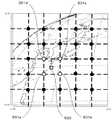
ここで、複数の基準ビーム方向とは、例えば、図15の黒点及び白点のように図15の上下左右に等間隔となるようにマトリクス状(格子状)に設定された方向である。この例では、図15の1つの点が1つの基準ビーム方向を示している。つまり、この例では、励振位相記憶装置52が記憶している励振位相の情報は、図15の黒点及び白点のそれぞれへ向けたビームを形成するための複数のアンテナ素子4の励振位相の情報である。 Here, the plurality of reference beam directions are, for example, directions set in a matrix (lattice) so as to be equally spaced vertically and horizontally in FIG. 15, such as black and white dots in FIG. 15. In this example, one point in FIG. 15 indicates one reference beam direction. That is, in this example, the excitation phase information stored in the excitation
次に、動作について説明する。ビーム走査位相演算回路50は、ビーム方向指令回路51からビーム出力指令を受けると、そのビーム出力指令に含まれる図15に示すような所望ビーム方向500の位置情報(例えば座標情報)に基づいて、所望ビーム方向500の周囲に位置する基準ビーム方向501a,501b,501c,501dについての励振位相の情報を励振位相記憶装置52から抽出する。 Next, the operation will be described. Upon receiving the beam output command from the beam
そして、ビーム走査位相演算回路50は、基準ビーム方向501a,501b,501c,501dと所望ビーム方向500との位置関係に基づき、基準ビーム方向501a,501b,501c,501dのそれぞれの励振位相を線形補間する。これにより、ビーム走査位相演算回路50は、励振位相目標値を算出する。この後、ビーム走査位相演算回路50は、算出した励振位相目標値の情報を移相制御回路38に送る。そして、移相制御回路38は、励振位相目標値に対応するように、各移相器11の移相量を設定する。 The beam scanning
従って、上記のような実施の形態5のアンテナ装置によれば、ビーム走査位相演算回路50は、ビーム方向指令回路51によって決定された所望ビーム方向と、励振位相記憶装置52の励振位相の情報に含まれる複数の基準ビーム方向との関係に基づき、複数の基準ビーム方向についての励振位相を補間して、励振位相目標値を算出する。この構成により、実施の形態3又は実施の形態4のアンテナ装置と同様の効果を得ることができるとともに、任意の方向にビーム走査を行うことができる。 Therefore, according to the antenna device of the fifth embodiment as described above, the beam scanning
なお、実施の形態5では、複数の基準ビーム方向がマトリクス状に配置されていたが、この例に限るものではない。複数の基準ビーム方向が、同心円状に(各円の円周上の任意の点として)配置されていてもよい。また、実施の形態5では、複数の基準ビーム方向が等間隔に配置されていたが、不等間隔に配置されていてもよい。 In the fifth embodiment, the plurality of reference beam directions are arranged in a matrix, but the present invention is not limited to this example. A plurality of reference beam directions may be arranged concentrically (as arbitrary points on the circumference of each circle). In the fifth embodiment, a plurality of reference beam directions are arranged at equal intervals, but may be arranged at unequal intervals.
また、実施の形態5では、ビーム走査位相演算回路50による補間方法として線形補間を用いた。しかしながら、ビーム走査位相演算回路50による補間方法は、線形補間に限定するものではなく、例えばスプライン補間等の他の補間方法を用いた場合でも同様の効果を得ることができる。 In the fifth embodiment, linear interpolation is used as an interpolation method by the beam scanning
さらに、実施の形態5では、ビーム走査位相演算回路50による励振位相目標値の演算方法として補間による方法を示した。しかしながら、ビーム走査位相演算回路50による励振位相目標値の演算方法は、この補間による方法に限定するものではない。例えば、ビーム走査位相演算回路50が、所望ビーム方向と基準ビーム方向との関係から、基準ビーム方向へ向けたビームの波面に傾きを与えるための励振位相を算出し、その算出した励振位相と基準ビーム方向についての励振位相とを足し合わせて、励振位相目標値を算出することもできる。 Further, in the fifth embodiment, the interpolation method is shown as the method for calculating the excitation phase target value by the beam scanning
また、実施の形態5では、実施の形態3又は実施の形態4のビーム形成回路7に、回路50,51及び装置52を追加した構成を示したが、実施の形態1又は実施の形態2のビーム形成回路に、回路50,51及び装置52を追加してもよく、この場合でも、実施の形態5と同様の効果を得ることができる。 In the fifth embodiment, the configuration in which the
さらに、実施の形態1〜5では、反射鏡導体1の形状は、回転放物面形状を例として説明した。しかしながら、反射鏡導体1の形状は、この例に限定するものではない。例えば、反射鏡導体1の形状は、回転楕円面形状若しくは回転双曲面形状、又は所望のアンテナパターンを実現するように鏡面修整が施された形状でもよい。 Furthermore, in Embodiment 1-5, the shape of the
1 反射鏡導体、2 フィードアレー、3 ビーム形成ユニット、4−1〜4−M アンテナ素子、5−1〜5−M 増幅器、7−1〜7−N ビーム形成回路、8,38 位相振幅制御回路(位相制御部)、11−1−1〜11−N−M 移相器、12−1−1〜12−N−M 減衰器、50 ビーム走査位相演算回路(ビーム走査位相演算部)、51 ビーム方向指令回路(ビーム指令部)、52 励振位相記憶装置(励振位相記憶部)、100 カバレッジエリア、111 狭ビーム、112 広ビーム、500 所望ビーム方向、501a,501b,501c,501d 基準ビーム方向。 DESCRIPTION OF
Claims (5)
Translated fromJapanese前記反射鏡導体の焦点から離れた位置に配置され、複数のアンテナ素子からなるフィードアレーと、
前記複数のアンテナ素子に接続された複数の増幅器と、
前記複数の増幅器を介して前記複数のアンテナ素子に接続され、前記複数のアンテナ素子の励振振幅及び励振位相をそれぞれ調整可能であり、励振振幅及び励振位相を調整することにより互いに異なるビーム幅の複数のビームを前記複数のアンテナ素子から放射させるビーム形成ユニットと
を備え、
前記ビーム形成ユニットの振幅調整量及び移相量は、
前記複数のビームのうちビーム幅の狭い狭ビームを所定のカバレッジエリアの中央部領域へ向けて前記複数のアンテナ素子から放射させるとともに、
前記複数のビームのうちビーム幅の広い広ビームを前記カバレッジエリアの端部領域へ向けて前記複数のアンテナ素子から放射させるように設定され、
かつ前記広ビームの送信電力を前記狭ビームの送信電力よりも高くすることで、前記複数のビームの全ての等価等方放射電力が同一となるように設定されている
ことを特徴とするアンテナ装置。A reflector conductor;
A feed array comprising a plurality of antenna elements disposed at a position away from the focal point of the reflector conductor;
A plurality of amplifiers connected to the plurality of antenna elements;
The plurality of antenna elements are connected to the plurality of antenna elements via the plurality of amplifiers, and the excitation amplitude and the excitation phase of the plurality of antenna elements can be respectively adjusted. By adjusting the excitation amplitude and the excitation phase, a plurality of different beam widths can be obtained. A beam forming unit for radiating a plurality of beams from the plurality of antenna elements,
The amplitude adjustment amount and the phase shift amount of the beam forming unit are:
A narrow beam having a narrow beam width among the plurality of beams is radiated from the plurality of antenna elements toward a central region of a predetermined coverage area, and
A wide beam having a wide beam width among the plurality of beams is set to radiate from the plurality of antenna elements toward an end region of the coverage area;
In addition, the antenna apparatus is characterized in that all the isotropic radiated powers of the plurality of beams are set to be the sameby making the transmission power of the wide beam higher than the transmission power of the narrow beam. .
ことを特徴とする請求項1記載のアンテナ装置。The amplitude adjustment amount and the phase shift amount of the beam forming unit are set so that the wide beam is radiated from the plurality of antenna elements toward a region where the user density is low and the communication traffic is low in the entire coverage area. The antenna device according to claim 1, wherein the antenna device is set.
それぞれ異なる方向である所定の複数の基準ビーム方向へ向けたビームを形成するための前記複数のアンテナ素子の励振位相の情報を予め記憶している励振位相記憶部と、
前記励振位相記憶部に記憶された前記励振位相の情報を用いて、前記ビーム指令部によって決定された前記所望ビーム方向にビームを形成するための励振位相目標値を算出するビーム走査位相演算部と、
前記ビーム形成ユニットの移相量を制御し、その移相量を、前記ビーム走査位相演算部によって算出された前記励振位相目標値に対応する移相量に設定する位相制御部と
をさらに備えることを特徴とする請求項1または2に記載のアンテナ装置。A beam command unit for determining a desired beam direction;
An excitation phase storage unit that stores in advance information of excitation phases of the plurality of antenna elements for forming beams directed to a plurality of predetermined reference beam directions that are respectively different directions;
A beam scanning phase calculation unit that calculates an excitation phase target value for forming a beam in the desired beam direction determined by the beam command unit using the excitation phase information stored in the excitation phase storage unit; ,
A phase control unit that controls a phase shift amount of the beam forming unit and sets the phase shift amount to a phase shift amount corresponding to the excitation phase target value calculated by the beam scanning phase calculation unit. The antenna device according to claim 1or 2 .
ことを特徴とする請求項3記載のアンテナ装置。The beam scanning phase calculation unit is based on a relationship between the desired beam direction determined by the beam command unit and the plurality of reference beam directions included in the excitation phase information stored in the excitation phase storage unit. The antenna device according to claim3 , wherein the excitation phase target value is calculated by interpolating the excitation phases with respect to the plurality of reference beam directions.
ことを特徴とする請求項3記載のアンテナ装置。The beam scanning phase calculation unit is based on the relationship between the desired beam direction determined by the beam command unit and the reference beam direction included in the excitation phase information stored in the excitation phase storage unit. Calculating an excitation phase for giving the inclination of the wavefront of the beam toward the reference beam direction, and adding the calculated excitation phase and the excitation phase for the reference beam direction to calculate the excitation phase target value; The antenna device according to claim3 .
Priority Applications (1)
| Application Number | Priority Date | Filing Date | Title |
|---|---|---|---|
| JP2009116968AJP5317821B2 (en) | 2009-05-13 | 2009-05-13 | Antenna device |
Applications Claiming Priority (1)
| Application Number | Priority Date | Filing Date | Title |
|---|---|---|---|
| JP2009116968AJP5317821B2 (en) | 2009-05-13 | 2009-05-13 | Antenna device |
Publications (2)
| Publication Number | Publication Date |
|---|---|
| JP2010268155A JP2010268155A (en) | 2010-11-25 |
| JP5317821B2true JP5317821B2 (en) | 2013-10-16 |
Family
ID=43364789
Family Applications (1)
| Application Number | Title | Priority Date | Filing Date |
|---|---|---|---|
| JP2009116968AExpired - Fee RelatedJP5317821B2 (en) | 2009-05-13 | 2009-05-13 | Antenna device |
Country Status (1)
| Country | Link |
|---|---|
| JP (1) | JP5317821B2 (en) |
Families Citing this family (2)
| Publication number | Priority date | Publication date | Assignee | Title |
|---|---|---|---|---|
| EP2869476A1 (en) | 2013-10-29 | 2015-05-06 | Alcatel Lucent | Transmitter Method For Multiple Antenna Systems, Transmitter Apparatus And Network Node Thereof |
| CN117039426A (en)* | 2023-07-29 | 2023-11-10 | 星启空间通信技术(南通)有限公司 | Satellite-borne multi-beam antenna and feed network |
Family Cites Families (9)
| Publication number | Priority date | Publication date | Assignee | Title |
|---|---|---|---|---|
| JPH02171038A (en)* | 1988-12-24 | 1990-07-02 | Mitsubishi Electric Corp | Multi-beam antenna method |
| JPH03158006A (en)* | 1989-11-15 | 1991-07-08 | Toshiba Corp | Satellite communication system |
| JPH1093337A (en)* | 1996-09-13 | 1998-04-10 | Toshiba Corp | Multi-beam antenna |
| US6137451A (en)* | 1997-10-30 | 2000-10-24 | Space Systems/Loral, Inc. | Multiple beam by shaped reflector antenna |
| US6141534A (en)* | 1998-03-25 | 2000-10-31 | Spacecode Llc | Communication satellite system with dynamic downlink resource allocation |
| JP2000216631A (en)* | 1999-01-26 | 2000-08-04 | Mitsubishi Electric Corp | Multi-beam antenna |
| US6140978A (en)* | 1999-09-08 | 2000-10-31 | Harris Corporation | Dual band hybrid solid/dichroic antenna reflector |
| JP4102382B2 (en)* | 2005-05-02 | 2008-06-18 | 三菱電機特機システム株式会社 | Weather radar equipment |
| JP5336709B2 (en)* | 2007-03-09 | 2013-11-06 | 三菱重工業株式会社 | Power supply system |
- 2009
- 2009-05-13JPJP2009116968Apatent/JP5317821B2/ennot_activeExpired - Fee Related
Also Published As
| Publication number | Publication date |
|---|---|
| JP2010268155A (en) | 2010-11-25 |
Similar Documents
| Publication | Publication Date | Title |
|---|---|---|
| EP3352299B1 (en) | Wideband beam broadening for phased array antenna systems | |
| US7864112B2 (en) | Beam-forming antenna with amplitude-controlled antenna elements | |
| US20170229786A1 (en) | Antenna System and Processing Method | |
| JP7110532B2 (en) | Array-fed reflector antenna | |
| Toso et al. | Multibeam antennas based on phased arrays: An overview on recent ESA developments | |
| JP6763633B2 (en) | Reflect array antenna | |
| JP5796759B2 (en) | Active phased array antenna device | |
| WO2014073222A1 (en) | Array-fed reflector antenna device and manufacturing method therefor | |
| JP5317821B2 (en) | Antenna device | |
| JP2014017708A (en) | Space synthesis antenna device and manufacturing method for modified mirror surface reflector | |
| CN115408880B (en) | A design method for overlapping multi-beam feed | |
| CN114270207A (en) | MIMO radar system | |
| Dubok et al. | Extreme scanning double shaped-reflector antenna with multiple interactions for focal plane array applications | |
| JP4005577B2 (en) | Phased array antenna apparatus and beam scanning control method | |
| KR101007213B1 (en) | Antenna combiner for multiple radiation patterns in radar systems | |
| KR102754606B1 (en) | WIRELESS POWER CHARGING APPARATUS FOR CHARGING IoT DEVICE | |
| JP3103335B2 (en) | Antenna device | |
| JP6425640B2 (en) | Radar equipment | |
| JP7457073B2 (en) | BEAM FORMING APPARATUS AND BEAM CONTROL METHOD | |
| TWI797919B (en) | Beamforming apparatus and beam controlling method | |
| JP4622966B2 (en) | Array antenna, array-fed reflector antenna, pointing direction error detection method and pointing direction error compensation method for both antennas | |
| KR20240120457A (en) | Transmitarray antenna for simultaneous beam forming and focusing | |
| JPH10242749A (en) | Multi-beam reflector antenna | |
| Bobkov et al. | Frequency-Independent Hybrid Multi-Beam Reflector Antenna | |
| JP6532305B2 (en) | Antenna device and radar device |
Legal Events
| Date | Code | Title | Description |
|---|---|---|---|
| A621 | Written request for application examination | Free format text:JAPANESE INTERMEDIATE CODE: A621 Effective date:20120130 | |
| A977 | Report on retrieval | Free format text:JAPANESE INTERMEDIATE CODE: A971007 Effective date:20130128 | |
| A131 | Notification of reasons for refusal | Free format text:JAPANESE INTERMEDIATE CODE: A131 Effective date:20130212 | |
| A521 | Request for written amendment filed | Free format text:JAPANESE INTERMEDIATE CODE: A523 Effective date:20130327 | |
| TRDD | Decision of grant or rejection written | ||
| A01 | Written decision to grant a patent or to grant a registration (utility model) | Free format text:JAPANESE INTERMEDIATE CODE: A01 Effective date:20130611 | |
| A61 | First payment of annual fees (during grant procedure) | Free format text:JAPANESE INTERMEDIATE CODE: A61 Effective date:20130709 | |
| R150 | Certificate of patent or registration of utility model | Ref document number:5317821 Country of ref document:JP Free format text:JAPANESE INTERMEDIATE CODE: R150 Free format text:JAPANESE INTERMEDIATE CODE: R150 | |
| R250 | Receipt of annual fees | Free format text:JAPANESE INTERMEDIATE CODE: R250 | |
| R250 | Receipt of annual fees | Free format text:JAPANESE INTERMEDIATE CODE: R250 | |
| R250 | Receipt of annual fees | Free format text:JAPANESE INTERMEDIATE CODE: R250 | |
| R250 | Receipt of annual fees | Free format text:JAPANESE INTERMEDIATE CODE: R250 | |
| R250 | Receipt of annual fees | Free format text:JAPANESE INTERMEDIATE CODE: R250 | |
| R250 | Receipt of annual fees | Free format text:JAPANESE INTERMEDIATE CODE: R250 | |
| R250 | Receipt of annual fees | Free format text:JAPANESE INTERMEDIATE CODE: R250 | |
| LAPS | Cancellation because of no payment of annual fees |