JP5317617B2 - Vehicle exhaust pipe structure - Google Patents
Vehicle exhaust pipe structureDownload PDFInfo
- Publication number
- JP5317617B2 JP5317617B2JP2008253175AJP2008253175AJP5317617B2JP 5317617 B2JP5317617 B2JP 5317617B2JP 2008253175 AJP2008253175 AJP 2008253175AJP 2008253175 AJP2008253175 AJP 2008253175AJP 5317617 B2JP5317617 B2JP 5317617B2
- Authority
- JP
- Japan
- Prior art keywords
- exhaust pipe
- vehicle
- frame
- width direction
- vehicle body
- Prior art date
- Legal status (The legal status is an assumption and is not a legal conclusion. Google has not performed a legal analysis and makes no representation as to the accuracy of the status listed.)
- Expired - Fee Related
Links
Images


Classifications
- B—PERFORMING OPERATIONS; TRANSPORTING
- B60—VEHICLES IN GENERAL
- B60K—ARRANGEMENT OR MOUNTING OF PROPULSION UNITS OR OF TRANSMISSIONS IN VEHICLES; ARRANGEMENT OR MOUNTING OF PLURAL DIVERSE PRIME-MOVERS IN VEHICLES; AUXILIARY DRIVES FOR VEHICLES; INSTRUMENTATION OR DASHBOARDS FOR VEHICLES; ARRANGEMENTS IN CONNECTION WITH COOLING, AIR INTAKE, GAS EXHAUST OR FUEL SUPPLY OF PROPULSION UNITS IN VEHICLES
- B60K13/00—Arrangement in connection with combustion air intake or gas exhaust of propulsion units
- B60K13/04—Arrangement in connection with combustion air intake or gas exhaust of propulsion units concerning exhaust
- F—MECHANICAL ENGINEERING; LIGHTING; HEATING; WEAPONS; BLASTING
- F01—MACHINES OR ENGINES IN GENERAL; ENGINE PLANTS IN GENERAL; STEAM ENGINES
- F01N—GAS-FLOW SILENCERS OR EXHAUST APPARATUS FOR MACHINES OR ENGINES IN GENERAL; GAS-FLOW SILENCERS OR EXHAUST APPARATUS FOR INTERNAL-COMBUSTION ENGINES
- F01N13/00—Exhaust or silencing apparatus characterised by constructional features
- F01N13/08—Other arrangements or adaptations of exhaust conduits
- F—MECHANICAL ENGINEERING; LIGHTING; HEATING; WEAPONS; BLASTING
- F01—MACHINES OR ENGINES IN GENERAL; ENGINE PLANTS IN GENERAL; STEAM ENGINES
- F01N—GAS-FLOW SILENCERS OR EXHAUST APPARATUS FOR MACHINES OR ENGINES IN GENERAL; GAS-FLOW SILENCERS OR EXHAUST APPARATUS FOR INTERNAL-COMBUSTION ENGINES
- F01N13/00—Exhaust or silencing apparatus characterised by constructional features
- F01N13/18—Construction facilitating manufacture, assembly, or disassembly
- F01N13/1805—Fixing exhaust manifolds, exhaust pipes or pipe sections to each other, to engine or to vehicle body
- F—MECHANICAL ENGINEERING; LIGHTING; HEATING; WEAPONS; BLASTING
- F01—MACHINES OR ENGINES IN GENERAL; ENGINE PLANTS IN GENERAL; STEAM ENGINES
- F01N—GAS-FLOW SILENCERS OR EXHAUST APPARATUS FOR MACHINES OR ENGINES IN GENERAL; GAS-FLOW SILENCERS OR EXHAUST APPARATUS FOR INTERNAL-COMBUSTION ENGINES
- F01N2340/00—Dimensional characteristics of the exhaust system, e.g. length, diameter or volume of the exhaust apparatus; Spatial arrangements of exhaust apparatuses
- F01N2340/04—Arrangement of the exhaust system relative to a vehicle or parts thereof
Landscapes
- Engineering & Computer Science (AREA)
- Chemical & Material Sciences (AREA)
- Combustion & Propulsion (AREA)
- Mechanical Engineering (AREA)
- General Engineering & Computer Science (AREA)
- Transportation (AREA)
- Cooling, Air Intake And Gas Exhaust, And Fuel Tank Arrangements In Propulsion Units (AREA)
- Body Structure For Vehicles (AREA)
- Automatic Cycles, And Cycles In General (AREA)
- Exhaust Silencers (AREA)
Abstract
Description
Translated fromJapanese本発明は、改良された車両の排気管構造に関する。 The present invention relates to an improved exhaust pipe structure for a vehicle.
従来、車体フレームのリヤフレーム部に内燃機関が配置された不整地走行車両が知られている(例えば、特許文献1参照。)。特許文献1に記載の不整地走行車両では、排気管は内燃機関の前部に取り付けられており、車体フレームによって囲まれた空間内で内燃機関を巻くように略螺旋形に形成されて後方に延び、車両後端に配置されたマフラーに連結されている。
ところで、内燃機関をリヤフレーム部に配置する車両において、車体を小型化するために車体フレームの上下寸法や幅を狭める場合、排気管の配管スペースが制約されてしまう。このような場合においても必要な管長さを確保するため、特許文献1に記載のような排気管を略螺旋形に屈曲配管すると、複雑な曲げ加工やコスト面で課題があった。 By the way, in a vehicle in which the internal combustion engine is arranged in the rear frame portion, when the vertical dimension or width of the vehicle body frame is reduced in order to reduce the size of the vehicle body, the piping space of the exhaust pipe is restricted. Even in such a case, if the exhaust pipe as described in
本発明は、前述した課題に鑑みてなされたものであり、その目的は、内燃機関が乗員用シート後方に配置されて車両後部のスペースが制約された車両においても、比較的簡単な構成で、必要とする排気管長さを確保することができる車両の排気管構造を提供することにある。 The present invention has been made in view of the above-described problems, and the purpose thereof is a relatively simple configuration even in a vehicle in which an internal combustion engine is arranged behind an occupant seat and a space at the rear of the vehicle is restricted. An object of the present invention is to provide an exhaust pipe structure for a vehicle that can secure the required exhaust pipe length.
上記目的を達成するために、請求項1に係る発明は、前輪駆動系を支持するフロントフレーム部と、乗員の居住空間を備えるセンタフレーム部と、後輪駆動系を支持するリヤフレーム部と、を有して車体を構成する車体フレームと、センタフレーム部に車幅方向に並んで配置されて運転席および助手席を構成する一対の乗員用シートと、乗員用シートより後方に配置されてリヤフレーム部の略車体中心線上に支持される内燃機関と、内燃機関に接続されて燃焼後の燃焼ガスを排気する排気管と、排気管に接続される消音器と、を備える車両の排気管構造であって、車両は後輪を左右に備え、消音器は、後輪の間で後輪の後端よりも更に後方に一部が延出するように配置され、排気管は、乗員用シートより後方で、略車体中心線上を直線状に前後方向に延びる上流側直線部及び下流側直線部と、上流側直線部及び下流側直線部にそれぞれ接続すると共に車幅方向外側に向けて張り出す略U字状の屈曲部と、を有し、上流側直線部と屈曲部との接続曲部と、下流側直線部と屈曲部との接続曲部と、の車体中心線に沿った前後方向の離間距離が、消音器の、後輪の後端からの後方延出長さよりも長く設定されることを特徴とする。In order to achieve the above object, the invention according to
請求項2に係る発明は、請求項1の構成に加えて、排気管は、水平面に対して上方または下方に傾斜しながら車幅方向外側に延び、車幅方向で運転席または助手席の後方領域に達した後、下方または上方に傾斜しながら略車体中心線上に戻ることを特徴とする。 According to a second aspect of the invention, in addition to the configuration of the first aspect, the exhaust pipe extends outward in the vehicle width direction while being inclined upward or downward with respect to the horizontal plane, and is located behind the driver seat or the passenger seat in the vehicle width direction. After reaching the area, the vehicle returns to the vehicle body center line while inclining downward or upward.
請求項3に係る発明は、請求項1または請求項2の構成に加えて、排気管は、内燃機関から前方に向かって延び、Uターンして後方に向かって延びた後、直線的に車幅方向外側に向かい、車幅方向内側に屈曲することで屈曲部を形成し、更にその後直線的に略車体中心線上に戻って下流側直線部を形成して、リヤフレーム部の略車体中心線上に設けられた消音器に接続されることを特徴とする。According to a third aspect of the present invention, in addition to the configuration of the first or second aspect, the exhaust pipe extends forward from the internal combustion engine, makes a U-turn and extends rearward, and then linearly moves the vehicle. toward the outside in the width directionto form a bent portion by bending inward in the vehicle widthdirection,to form the downstream-side straight portion IThereafter linearly back substantially on the body center line, substantially the center of the vehicle body of the rear frame portion It is connected to a silencer provided on the line.
請求項4に係る発明は、請求項1から請求項3のいずれかの構成に加えて、フロントロアフレーム、センターロアフレーム、およびリヤロアフレームからなり、前記車体の左右下部に配置されて前後方向に延びる一対のロアフレームと、リヤロアフレームの後端から上方に延びた後、内燃機関を覆うように屈曲して前方に延設される左右一対のリヤアッパフレームと、各リヤアッパフレームと各ロアフレームとをそれぞれ連結する一対のリヤ起立フレームと、リヤフレーム部に取り付けられる後輪懸架装置と、を更に備え、排気管は、車幅方向外側に向かって延出した後、リヤ起立フレームの車体内側を通り略車体中心線上に戻ることを特徴とする。 The invention according to claim 4 includes a front lower frame, a center lower frame, and a rear lower frame in addition to the structure of any one of
請求項5に係る発明は、請求項4の構成に加えて、センターロアフレームの車幅方向外側において前後方向に延びる左右一対のサイドフレームを更に備え、排気管の屈曲部は、サイドフレームの後方延長線上より車幅方向内側、且つリヤアッパフレームまたはリヤロアフレームより車幅方向外側まで延出することを特徴とする。The invention according to
請求項6に係る発明は、請求項1から請求項5のいずれかの構成に加えて、排気管の屈曲部は、空気を内燃機関に供給する吸気系が配置される運転席と助手席の一方の後方領域と異なる、他方の後方領域に配置されることを特徴とする。According to a sixth aspect of the present invention, in addition to the configuration of any of the first to fifth aspects, thebent portion of the exhaust pipe includes a driver seat and a passenger seat in which an intake system that supplies air to the internal combustion engine is disposed. It is arranged in the other rear region, which is different from the one rear region.
請求項7に係る発明は、請求項1から請求項6のいずれかの構成に加えて、排気管の屈曲部は、平面視で後輪より車幅方向内側に配置されることを特徴とする。The invention according to
請求項1の発明によれば、排気管は、乗員用シートより後方で、略車体中心線上を直線状に前後方向に延びる上流側直線部及び下流側直線部と、上流側直線部及び下流側直線部にそれぞれ接続すると共に車幅方向外側に向けて張り出す略U字状の屈曲部と、を有するので、内燃機関が乗員用シート後方に配置されて、車体後部のスペースが制約された、例えば低床化された車両においても、デッドスペースを利用し排気管の長さを長くして必要とする排気管長さを確保することができる。
またこのとき、車両は後輪を左右に備え、消音器は、後輪の間で後輪の後端よりも更に後方に一部が延出するように配置され、上流側直線部と屈曲部との接続曲部と、下流側直線部と屈曲部との接続曲部と、の車体中心線に沿った前後方向の離間距離が、消音器の、前記後輪の後端からの後方延出長さよりも長く設定されると好適である。According to the first aspect of the present invention, the exhaust pipe is located behind the occupant seatand extends substantially linearly on the vehicle body center line in the front-rear direction, and the upstream linear portion and the downstream linear portion, and the upstream linear portion and the downstream side. Since it has a substantially U-shaped bent portion that is connected to each of the straight portions and projects outward in the vehicle width direction , the internal combustion engine is disposed behind the occupant seat, and the space at the rear of the vehicle body is restricted. For example, even in a vehicle with a low floor, a necessary exhaust pipe length can be ensured by using a dead space and increasing the length of the exhaust pipe.
Also, at this time, the vehicle has rear wheels on the left and right sides, and the silencer is arranged between the rear wheels so that a part extends further rearward than the rear end of the rear wheels, and the upstream linear portion and the bent portion The distance between the connecting curved portion of the front end and the connecting curved portion of the downstream linear portion and the bent portion along the vehicle body center line extends rearward from the rear end of the rear wheel of the silencer. It is preferable to set it longer than the length.
請求項2の発明によれば、排気管は、水平面に対して上方または下方に傾斜しながら車体外側方向に延びた後、下方または上方に傾斜しながら略車体中心線上に戻るようにしたので、内燃機関が乗員用シート後方に配置されて車体後部のスペースが制約された車両においても、排気管の長さを長くして必要とする排気管長さを確保することができる。 According to the invention of claim 2, since the exhaust pipe extends in the vehicle body outer side direction while being inclined upward or downward with respect to the horizontal plane, the exhaust pipe is returned to substantially the vehicle body center line while being inclined downward or upward. Even in a vehicle in which the internal combustion engine is disposed behind the passenger seat and the space at the rear of the vehicle body is restricted, the length of the exhaust pipe can be increased to ensure the required exhaust pipe length.
請求項3の発明によれば、排気管は、内燃機関から前方に向かって延び、Uターンして後方に向かって延びた後、直線的に車体外側方向に向かい、車体内側方向に屈曲することで屈曲部を形成し、更にその後直線的に略車体中心線上に戻って下流側直線部を形成して、前記リヤフレーム部の消音器に接続するようにしたので、排気管の長さを長くして必要とする排気管長さを確保すると共に排気管の直線部分を多くして、加工および組立て工数を低減させて排気管の製作費を抑制することができる。According to the invention of claim 3, the exhaust pipe extends forward from the internal combustion engine, U-turns and extends rearward, and then linearly faces the vehicle body outward direction and bendsin the vehicle body inner direction.in a bent portion is formed, further followedby forming the downstream-side straight portion I linearly back substantially on the body center line, since to be connected to a muffler of the rear frame portion, the length of the exhaust pipe The required length of the exhaust pipe can be increased by increasing the length and the straight portion of the exhaust pipe can be increased to reduce the processing and assembly man-hours, thereby suppressing the manufacturing cost of the exhaust pipe.
請求項4の発明によれば、排気管は、車体外側方向に向かって延出した後、リヤ起立フレームの車体内側を通り略車体中心線上に戻るようにしたので、リヤ起立フレームより後方においてリヤフレーム部に配設された後輪懸架装置のデッドスペースを有効利用することができる。 According to the fourth aspect of the present invention, the exhaust pipe extends toward the outer side of the vehicle body and then passes through the inner side of the rear standing frame to return to the substantially center line of the vehicle body. The dead space of the rear wheel suspension device disposed in the frame portion can be effectively used.
請求項5の発明によれば、排気管の屈曲部は、サイドフレームの後方延長線上より車幅方向内側、且つリヤアッパフレームまたはリヤロアフレームより車幅方向外側まで延出するようにしたので、排気管の長さを確保しつつ、排気管を保護することができる。According to the invention of
請求項6の発明によれば、排気管の屈曲部は、空気を内燃機関に供給する吸気系が配置される運転席と助手席の一方の後方領域と異なる、他方の後方領域に配置されるので、乗員用シートより後方のスペースを有効利用した効果的なレイアウトが可能であり、また、左右の重量バランスがよい。According to the invention of
請求項7の発明によれば、排気管の屈曲部は、平面視で後輪より車幅方向内側に配置されるので、排気管を保護することができる。According to the seventh aspect of the present invention, thebent portion of the exhaust pipe is disposed on the inner side in the vehicle width direction from the rear wheel in plan view, so that the exhaust pipe can be protected.
以下、本発明の車両のフレーム構造に係る一実施形態について、MUV(マルチ・ユーティリティ・ビークル)を例にとって説明する。なお、図面は符号の向きに見るものとする。 Hereinafter, an embodiment of the frame structure of a vehicle according to the present invention will be described by taking MUV (multi-utility vehicle) as an example. The drawings are viewed in the direction of the reference numerals.
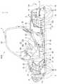
図1〜図3に示すように、本実施形態に係る車両1は、フロントフレーム部2と、センタフレーム部3と、リヤフレーム部4とを有して車体Bを構成する車体フレーム30を備える。フロントフレーム部2には、左右の前輪5を懸架する前輪用懸架装置(図示せず)が取り付けられ、フロントディファレンシャルギヤユニット81、フロントドライブシャフト82等の前輪駆動系や、前輪5を操舵する操舵部材(ステアリングシャフト6、このステアリングシャフト6の上端に取り付けたハンドル7を含む)等が支持されている。 As shown in FIGS. 1 to 3, the
センタフレーム部3には、車幅方向に並んで配置された運転席9および助手席10を構成する一対の乗員用シート11が取り付けられており、乗員の居住空間を構成する。助手席10の下部空間には、燃料タンク12が配設されると共に、運転席9と助手席10との間には、パワーユニットPとフロントディファレンシャルギヤユニット81とを連結するフロントプロペラシャフト83が配置されている。 A pair of
リヤフレーム部4には、左右の後輪15を懸架する後輪用懸架装置(図示せず)が取り付けられ、内燃機関13および変速機14を含むパワーユニットPに加え、リヤプロペラシャフト86、リヤディファレンシャルギヤユニット、リヤドライブシャフト85等の後輪駆動系等が支持されている。 A rear wheel suspension device (not shown) for suspending the left and right
図3に示すように、リヤフレーム部4に支持されたパワーユニットPは、内燃機関13のクランクシャフト16が車体前後方向に向けて配置された縦置きレイアウトとされている。クランクシャフト16から動力が伝達される出力軸80は、略車体中心線CL上に配置され、その前端は、フロントプロペラシャフト83に連結され、後端はリヤプロペラシャフト86に連結されている。 As shown in FIG. 3, the power unit P supported by the rear frame portion 4 has a vertical layout in which the
リヤプロペラシャフト86は、略車体中心線CL上に配置されたリヤディファレンシャルギヤユニット84に接続されており、内燃機関13の駆動力は、リヤプロペラシャフト86、リヤディファレンシャルギヤユニット84、及び、リヤディファレンシャルギヤユニット84に接続されたリヤドライブシャフト85を介して左右の後輪15に伝達される。 The
フロントプロペラシャフト83には、その中間部にリダクションギヤ90が設けられており、フロントプロペラシャフト83は、リダクションギヤ90より後方に配置された第1プロペラシャフト87と、リダクションギヤ90より前方に配置された第2プロペラシャフト88とで構成される。リダクションギヤ90は、前輪5と後輪15を同一方向に回転させるため、第1プロペラシャフト87の回転方向を逆方向に変換して第2プロペラシャフト88に伝達する。これにより、内燃機関13の駆動力は、第1プロペラシャフト87、リダクションギヤ90、第2プロペラシャフト88、フロントディファレンシャルギヤユニット81、及び、フロントディファレンシャルギヤユニット81に接続されたフロントドライブシャフト82を介して左右の前輪5に伝達される。 The
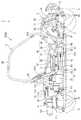
図8に拡大して示すように、内燃機関13のシリンダヘッド18の後部には、スロットルバルブユニット19がインテークマニホールド20を通じて接続されており、シリンダヘッド18の前部には、後述する排気管120が接続されている。スロットルバルブユニット19の後部には、後述する第1及び第2エアクリーナ室111、112を備えたエアクリーナ110がコネクティングチューブ117を介して接続される。また、スロットルバルブユニット19には、燃料タンク12から延びる燃料配管21と、バッテリケース22やECU26等を備えたバッテリケース22から配索されたワイヤハーネス23が接続されている。 As shown in an enlarged view in FIG. 8, a
さらに、図2及び図4に示すように、内燃機関13には、フロントフレーム部2に配置されたラジエータ24が2本の水配管25によって接続されており、内燃機関13を冷却する冷却水は、水配管25を介してラジエータ24との間を循環する。 Further, as shown in FIGS. 2 and 4, the
なお、図1中、26はフロントカバー、27はインストルメントパネル、28は、中央のカバー部材28aと左右一対のカバー部材28bとからなるセンターコンソールカバーである。 In FIG. 1, 26 is a front cover, 27 is an instrument panel, and 28 is a center console cover comprising a
図4及び図5に示すように、車体フレーム30は、車体Bの左右下部に配置されて前後方向に延び、車体Bの前方から、フロントロアフレーム31と、センターロアフレーム32と、リヤロアフレーム33とを構成する一対のロアフレーム34を有する。 As shown in FIGS. 4 and 5, the
フロントフレーム部2では、フロントロアフレーム31の先端から、左右一対のフロントアッパフレーム70が上方に向かって延びた後、更に後方に延設されて前アッパクロスメンバ44に連結されて、車体Bの前部上方を覆っている。フロントロアフレーム31およびフロントアッパフレーム70は、コの字型フレーム71によって互いに結合されている。 In the front frame portion 2, a pair of left and right front
また、コの字型フレーム71とフロントアッパフレーム70の立上り部同士は、略L字型に形成されたフロントサスペンション支持パイプ72によって連結されている。フロントロアフレーム31およびフロントサスペンション支持パイプ72にそれぞれ2個ずつ固定されたブラケット63には、左右の前輪5を回転自在に懸架する前輪用懸架装置が揺動自在に配設されている。 The rising portions of the
一方、リヤフレーム部4では、左右一対のリヤアッパフレーム75がリヤロアフレーム33の後端から上方に延びた後、内燃機関13を含むパワーユニットPを覆うように屈曲して前方に延設され、センターロアフレーム32の乗員用シート11の後方から上方に延びる一対のセンター起立フレーム40に連結されている。リヤアッパフレーム75の水平部とリヤロアフレーム33とは、下方に向かうにつれて前方に傾斜するリヤ起立フレーム76によって上下方向に連結されている。また、リヤアッパフレーム75の垂直部とリヤ起立フレーム76とは、リヤサスペンション支持パイプ77によって連結されている。 On the other hand, in the rear frame portion 4, a pair of left and right rear
リヤロアフレーム33及びリヤサスペンション支持パイプ77に、それぞれ前後に2個ずつ固定された合計4個のブラケット78には、左右の後輪15を回転自在に懸架する後輪用懸架装置が揺動自在に配設されている。 A total of four
センタフレーム部3では、センターロアフレーム32の車幅方向外側に、センターロアフレーム32の前方に結合された結合パイプ66と、センター起立フレーム40の中間部に連結された結合パイプ67よって各ロアフレーム34とそれぞれ連結される左右一対のサイドフレーム51が前後方向に延びて配置されている。 In the center frame portion 3, each lower frame is connected to the outer side in the vehicle width direction of the center
サイドフレーム51は、前立上り部51aと、後立上り部51bと、前立上り部51aと後立上り部51bとを連結する水平部51cとによって下方に凸の略コの字型に形成されている。 The
略コの字型のサイドフレーム51は、サイドパイプ52によって前立上り部51aと後立上り部51bとが、前後方向に連結されている。一対のサイドフレーム51の前立上り部51aの端部同士は、前アッパクロスメンバ44によって車幅方向に連結されている。後立上り部51bの中間部と水平部51cの中間部とは、略L字型のシート支持用パイプ53によって連結されている。 In the substantially
一対のサイドフレーム51の前立上り部51aおよび後立上り部51bには、略コの字型に形成された一対のサイドアッパフレーム55が、上方に凸とされて連結されている。一対のサイドアッパフレーム55は、一対のセンター起立フレーム40の上端部が結合される第1アッパクロスメンバ54、2本のルーフクロスメンバ56、57、及び、第1アッパクロスメンバ54とも中間部で連結されるヘッドレスト用クロスメンバ58によって車幅方向に連結されている。 A pair of side
一対のシート支持用パイプ53には、ブラケットを介して第1シートクロスメンバ61が掛け渡されている。また、各サイドフレーム51の後立上り部51bには、1対のセンター起立フレーム40の中間部下方同士を車幅方向に連結する後クロスメンバ64とそれぞれ結合される一対の第2シートクロスメンバ62がブラケットを介して連結されている。これにより、第1及び第2シートクロスメンバ61,62と、これら第1及び第2シートクロスメンバ61、62とを前後方向に連結する連結フレーム65とはシートフレームを構成し、運転席9および助手席10のシートパイプ60(図9参照)はこれらシートフレーム上に取り付けられる。 A first
また、センタフレーム部3には、運転席9と助手席10との間を通り、ロアフレーム34の上方において略車体中心線CL上に前後方向に配置されたセンターパイプ35が設けられる。従って、センタフレーム部3は、車幅方向中央部にセンターパイプ35とロアフレーム34とが上下に配置され、サイド部にサイドパイプ52とサイドフレーム51とが上下に配置された構造となる。これにより、センタフレーム部3の剛性が向上すると共に、低床化、低重心化が可能となる。 Further, the center frame portion 3 is provided with a
図7にも拡大して示すように、センターパイプ35は、アッパセンターパイプ36と、ダウンセンターパイプ37と、起立センターパイプ38と、フロントセンターパイプ39と、を備え、各部材36,37,38,39は乗員用シート11より前方の結合点Jで交わり互いに結合されている。 7, the
アッパセンターパイプ36は、一対のセンター起立フレーム40同士を連結する後アッパクロスメンバ41の中央に一端が結合されて前方に延びる。ダウンセンターパイプ37は、センターロアフレーム32の乗員用シート11より下方に設けられた後ロアクロスメンバ42の中央に一端が結合されて前上方に延びる。 The
起立センターパイプ38は、センターロアフレーム32の乗員用シート11前方に設けられた前ロアクロスメンバ43の中央に一端が結合されて後上方に延びる。また、フロントセンターパイプ39は、結合点Jを基点として前方に向かって左右二股に形成された略V字型のパイプ部材であり、左右二股の端部は、フロントアッパフレーム70と前アッパクロスメンバ44との連結部近傍で前アッパクロスメンバ44に連結される。 The standing
このように構成されるセンターパイプ35では、剛性が高くなった結合点J近傍の上方に、シフトレバー105が取り付けられ、また、アッパセンターパイプ36の中間部上方には、サイドブレーキレバー106が取り付けられている。なお、前アッパクロスメンバ44には、サブフレーム107を介して操舵部材であるステアリングシャフト6が取り付けられており、これらシフトレバー105、サイドブレーキレバー106、ステアリングシャフト6に加え、運転席9側に配置されたブレーキペダルやアクセルペダル等の足操作子91等から延びる各配線は、電気接続箱103に集約された後、一本のワイヤハーネス104として束ねられて運転席9の後方に設けられたバッテリケース22に接続される。 In the
また、図2、図3、及び図7に示すように、第1プロペラシャフト87は、センターパイプ35の下方で、センターパイプ35に沿って略車体中心線CL上に位置し、側面視において燃料タンク12と重なるように、換言すれば、燃料タンク12と車幅方向に並んで配置されている。リダクションギヤ90に接続された第2プロペラシャフト88は、第1プロペラシャフト87に対して車幅方向助手席10側にオフセットして配置されている。さらに、第2プロペラシャフト88は、フロントロアフレーム31の略車体中心線CL上に配設されたフロントディファレンシャルギヤユニット81に助手席10側で連結されている。 As shown in FIGS. 2, 3, and 7, the
このように、フロントプロペラシャフト83は、ほぼセンターパイプ35に沿って配置されているので、車両1の捩れ力がフロントプロペラシャフト83に作用し難い構造となっている。また、第2プロペラシャフト88が車幅方向助手席10側にオフセットして配置されているので、低床化されても乗員の居住空間を大きくとることができると共に、足操作子91のレイアウトの自由度が向上し、操作性のよい位置に配置することができる。 Thus, since the
また、リダクションギヤ90は、運転席9側に配置されたブレーキペダルやアクセルペダル等の足操作子91より後方、且つ一対の乗員用シート11より前方に位置し、ダウンセンターパイプ37と起立センターパイプ38との間に配置されている。 The
ラジエータ24と内燃機関13とを接続する2本の水配管25や電気接続箱103とバッテリケース22とを電気的に接続するワイヤハーネス104も、フロントプロペラシャフト83と同様に、起立センターパイプ38より前方では車幅方向助手席10側にオフセットして配置されている。 The two
このため、運転席9と助手席10との間に設けられたセンターコンソールカバー28は、その前部が助手席側にオフセットされた状態で、これらセンターパイプ35、フロントプロペラシャフト83、リダクションギヤ90、水配管25、ワイヤハーネス104、シフトレバー105、サイドブレーキレバー106を収容する。 For this reason, the
これにより、水配管25、およびワイヤハーネス104は、デッドスペースを利用してコンパクトに配置され、乗員の居住空間を大きくとることができると共に、足操作子91のレイアウトの自由度が向上し、操作性のよい位置に配置することができる。 As a result, the
また、車体フレーム30が左右対称形に配置され、且つ主な重量物であるフロントディファレンシャルギヤユニット81、リダクションギヤ90、内燃機関13、リヤディファレンシャルギヤユニット84等が略車体中心線CL上に配置されているので、左右の重量バランスが良好となり、車両1の安定性が増大する。 The
図8〜図10に示すように、吸気系を構成するエアクリーナ110は、助手席10の後方、且つ内燃機関13の右側方に配置されており、第1エアクリーナ室111と第2エアクリーナ室112とを備える。 As shown in FIGS. 8 to 10, the
第1エアクリーナ室111には、助手席10の後方に配置され、開口を覆うカバー114を備えたシュノーケル113が、その車幅方向外側面に取り付けられたダクトを介して接続される。第1エアクリーナ室111と第2エアクリーナ室112は、リヤ起立フレーム76の一部を跨ぐようにして車幅方向に対向しており、接続チューブ116によって連通される。また、第2エアクリーナ室112は、コネクティングチューブ117によって内燃機関13に接続される。 A
これにより、第1エアクリーナ室111がリヤ起立フレーム76の車幅方向外側に配置され、第2エアクリーナ室112がリヤ起立フレーム76の車幅方向内側に配置される。また、空気中の塵埃を除去するエアクリーナエレメント115は、第1エアクリーナ室111内に収容されている。 As a result, the first air
このようなエアクリーナ110は、シュノーケル113から外部空気を導入し、第1エアクリーナ室111のエアクリーナエレメント115によって空気中の塵埃が除去され、接続チューブ116を通って第2エアクリーナ室112に導かれた後、コネクティングチューブ117から浄化された空気が内燃機関13へ供給される。 After
エアクリーナ110は、ロアフレーム34の車幅方向外側に配置された第1エアクリーナ室111と、車幅方向内側に配置された第2エアクリーナ室112とを備えるので、フレームで囲まれた狭い空間内に、大きな容量のエアクリーナ110をコンパクトに配置することができる。また、第1エアクリーナ室111がリヤ起立フレーム76の車幅方向外側に配置されているので、エアクリーナ110のメンテナンススペースが広くなり、メンテナンス作業を容易に行うことができ、整備性に優れる。
なお、第1エアクリーナ室111と第2エアクリーナ室112は、取付位置に応じて、リヤ起立フレーム76の他、ロアフレーム34やリヤアッパフレーム75の一部を跨ぐように配置される場合にも、上記効果を奏する。Since the
Note that the first air
また、図8及び図11に示すように、シリンダヘッド18の前部に接続された排気管120は、前方に向かって延びた後、Uターンして後方に向かって延び、さらに略90°で屈曲し、水平面に対して下方に傾斜しながら直線的に車体外方に向かって延びる。さらに、排気管120は、車幅方向で運転席9の後方領域に達した後、車体内方に屈曲して上方に傾斜しながら直線的に略車体中心線CL上に戻り、リヤフレーム部4の略車体中心線CL上に前後方向に向けて配設された消音器122に接続している。これにより、排気管120の最外方延出部である屈曲部121は、サイドフレーム51の後方延長線上より車幅方向内側、且つリヤアッパフレーム75より車幅方向外側まで延出している。Further, as shown in FIGS. 8 and 11, the
従って、内燃機関13が乗員用シート11後方に配置されて、リヤフレーム部4のスペースが制約された、例えば低床化された車両1においても、デッドスペースを利用し排気管120の長さを必要長さだけ確保することができる。また、排気管120の直線部分が多いので、加工が容易であり、組立て工数を低減して制作費を抑制することができる。 Therefore, even in the
排気管120の屈曲部121は、サイドフレーム51の後方延長線上より車幅方向内側、且つリヤアッパフレーム75より車幅方向外側まで延出している。これにより、排気管120の長さを確保しつつ、排気管120が保護される。The
また、排気管120は、リヤ起立フレーム76の車体内側を通り略車体中心線CL上に戻るので、リヤ起立フレーム76より後方に配設された後輪用懸架装置のデッドスペースを有効利用することができる。 Further, the
以上説明したように、本実施形態に係る車両の排気管構造によれば、排気管120は、乗員用シート11後方で車体外側方向に延びた後、車体内側方向に略U字状に屈曲して略車体中心線CL上に戻るようにしたので、内燃機関13が乗員用シート11後方に配置されて、車体後部のスペースが制約された、例えば低床化された車両1においても、デッドスペースを利用し排気管120の長さを長くして必要とする排気管長さを確保することができる。 As described above, according to the exhaust pipe structure for a vehicle according to the present embodiment, the
また、排気管120は、水平面に対して上方または下方に傾斜しながら車体外側方向に延び、運転席9または助手席10の後方領域に達した後、下方または上方に傾斜しながら略車体中心線CL上に戻るようにしたので、内燃機関13が乗員用シート11後方に配置されて車体後部のスペースが制約された車両1においても、排気管120の長さを長くして必要とする排気管長さを確保することができる。 Further, the
さらに、排気管120は、内燃機関13から前方に向かって延び、Uターンして後方に向かって延びた後、直線的に車体外側方向に向かい、車体内側方向に屈曲して直線的に略車体中心線CL上に戻り、リヤフレーム部4の消音器122に接続するようにしたので、排気管120の長さを長くして必要とする排気管長さを確保すると共に排気管120の直線部分を多くして、加工および組立て工数を低減させて排気管120の製作費を抑制することができる。 Further, the
加えて、排気管120は、車体外側方向に向かって延出した後、リヤ起立フレーム76の車体内側を通り略車体中心線CL上に戻るようにしたので、リヤ起立フレーム76より後方においてリヤフレーム部4に配設された後輪懸架装置のデッドスペースを有効利用することができる。 In addition, the
また、排気管120の屈曲部121は、サイドフレーム51の後方延長線上より車幅方向内側、且つリヤアッパフレーム75またはリヤロアフレーム33より車幅方向外側まで延出するようにしたので、排気管120の長さを確保しつつ、排気管120を保護することができる。Further, the
また、排気管120の屈曲部121は、空気を内燃機関13に供給する吸気系が配置される助手席10の後方領域と異なる、運転席9の後方領域に配置されるので、乗員用シート11より後方のスペースを有効利用した効果的なレイアウトが可能であり、また、左右の重量バランスがよい。Further, the
さらに、排気管120の屈曲部121は、平面視で後輪15より車幅方向内側に配置されるので、排気管120を保護することができる。Furthermore, since the
尚、本発明は、前述した実施形態に限定されるものではなく、適宜、変形、改良等が可能である。例えば、本発明においては、MUV(マルチ・ユーティリティ・ビークル)に適用したものとして説明したが、これに限定されるものではなく、4輪以上の車輪を有する任意の形式の車両にも同様に適用することができる。 In addition, this invention is not limited to embodiment mentioned above, A deformation | transformation, improvement, etc. are possible suitably. For example, although the present invention has been described as applied to an MUV (multi-utility vehicle), the present invention is not limited to this, and is similarly applied to any type of vehicle having four or more wheels. can do.
1 車両
2 フロントフレーム部
3 センタフレーム部
4 リヤフレーム部
9 運転席
10 助手席
11 乗員用シート
13 内燃機関
30 車体フレーム
31 フロントロアフレーム
32 センターロアフレーム
33 リヤロアフレーム
34 ロアフレーム
51 サイドフレーム
75 リヤアッパフレーム
76 リヤ起立フレーム
81 フロントディファレンシャルギヤユニット(前輪駆動系)
82 フロントドライブシャフト(前輪駆動系)
84 リヤディファレンシャルギヤユニット(後輪駆動系)
85 リヤドライブシャフト(後輪駆動系)
120 排気管
122 消音器
B 車体
CL 車体中心線DESCRIPTION OF
82 Front drive shaft (front wheel drive system)
84 Rear differential gear unit (rear wheel drive system)
85 Rear drive shaft (rear wheel drive system)
120
Claims (7)
Translated fromJapanese前記車両は後輪を左右に備え、
前記消音器は、前記後輪の間で前記後輪の後端よりも更に後方に一部が延出するように配置され、
前記排気管は、前記乗員用シートより後方で、略車体中心線上を直線状に前後方向に延びる上流側直線部及び下流側直線部と、前記上流側直線部及び前記下流側直線部にそれぞれ接続すると共に車幅方向外側に向けて張り出す略U字状の屈曲部と、を有し、
前記上流側直線部と前記屈曲部との接続曲部と、前記下流側直線部と前記屈曲部との接続曲部と、の車体中心線に沿った前後方向の離間距離が、前記消音器の、前記後輪の後端からの後方延出長さよりも長く設定されることを特徴とする車両の排気管構造。A vehicle body frame that includes a front frame portion that supports a front wheel drive system, a center frame portion that includes a passenger's living space, and a rear frame portion that supports a rear wheel drive system, and the center frame portion. A pair of occupant seats that are arranged side by side in the vehicle width direction to form a driver seat and a passenger seat, and an internal combustion engine that is disposed behind the occupant seat and is supported on a substantially vehicle body center line of the rear frame portion An exhaust pipe structure of a vehicle comprising: an exhaust pipe connected to the internal combustion engine for exhausting combustion gas after combustion; and a silencer connected to the exhaust pipe,
The vehicle has rear wheels on the left and right,
The silencer is arranged between the rear wheels such that a part extends further rearward than the rear end of the rear wheel,
The exhaust pipe is connected to the upstream straight line portion and the downstream straight line portion that extend in the front-rear direction substantially linearly on the vehicle body center line behind the passenger seat, and to the upstream straight line portion and the downstream straight line portion, respectively. And a substantially U-shaped bent portion that protrudes outward in the vehicle width direction,
A distance in the front-rear direction along the vehicle center line of the connecting curved portion between the upstream linear portion and the bent portion and the connecting curved portion between the downstream linear portion and the bent portion is determined by the silencer. An exhaust pipe structure for a vehicle, wherein the exhaust pipe structure is set longer than a rear extension length from a rear end of the rear wheel.
前記リヤロアフレームの後端から上方に延びた後、前記内燃機関を覆うように屈曲して前方に延設される左右一対のリヤアッパフレームと、
前記各リヤアッパフレームと前記各ロアフレームとをそれぞれ連結する一対のリヤ起立フレームと、
前記リヤフレーム部に取り付けられる後輪懸架装置と、
を更に備え、
前記排気管は、前記車幅方向外側に向かって延出した後、前記リヤ起立フレームの車体内側を通り略車体中心線上に戻ることを特徴とする請求項1から請求項3のいずれかに記載の車両の排気管構造。A pair of lower frames, which are composed of a front lower frame, a center lower frame, and a rear lower frame, are arranged in the left and right lower portions of the vehicle body and extend in the front-rear direction;
A pair of left and right rear upper frames that extend upward from the rear end of the rear lower frame and then bend and extend forward to cover the internal combustion engine;
A pair of rear upright frames connecting the respective rear upper frames and the respective lower frames;
A rear wheel suspension device attached to the rear frame part;
Further comprising
4. The exhaust pipe according to claim 1, wherein the exhaust pipe extends toward the outside in the vehicle width direction, and then returns to the substantially vehicle body center line through the vehicle body inner side of the rear standing frame. Vehicle exhaust pipe structure.
前記排気管の前記屈曲部は、前記サイドフレームの後方延長線上より車幅方向内側、且つ前記リヤアッパフレームまたは前記リヤロアフレームより車幅方向外側まで延出することを特徴とする請求項4に記載の車両の排気管構造。A pair of left and right side frames extending in the front-rear direction on the vehicle width direction outer side of the center lower frame;
The bent portion of the exhaust pipe, toclaim 4, characterized in that extending in the vehicle width direction inner side than on the posterior extension, and than the rear upper frame or the rear lower frame to the vehicle width direction outer side of the side frame The vehicle exhaust pipe structure as described.
Priority Applications (3)
| Application Number | Priority Date | Filing Date | Title |
|---|---|---|---|
| JP2008253175AJP5317617B2 (en) | 2008-09-30 | 2008-09-30 | Vehicle exhaust pipe structure |
| CA2672285ACA2672285C (en) | 2008-09-30 | 2009-07-16 | Exhaust pipe structure of vehicle |
| US12/558,576US8215443B2 (en) | 2008-09-30 | 2009-09-14 | Exhaust pipe structure of vehicle and vehicle |
Applications Claiming Priority (1)
| Application Number | Priority Date | Filing Date | Title |
|---|---|---|---|
| JP2008253175AJP5317617B2 (en) | 2008-09-30 | 2008-09-30 | Vehicle exhaust pipe structure |
Publications (2)
| Publication Number | Publication Date |
|---|---|
| JP2010083273A JP2010083273A (en) | 2010-04-15 |
| JP5317617B2true JP5317617B2 (en) | 2013-10-16 |
Family
ID=42056197
Family Applications (1)
| Application Number | Title | Priority Date | Filing Date |
|---|---|---|---|
| JP2008253175AExpired - Fee RelatedJP5317617B2 (en) | 2008-09-30 | 2008-09-30 | Vehicle exhaust pipe structure |
Country Status (3)
| Country | Link |
|---|---|
| US (1) | US8215443B2 (en) |
| JP (1) | JP5317617B2 (en) |
| CA (1) | CA2672285C (en) |
Families Citing this family (14)
| Publication number | Priority date | Publication date | Assignee | Title |
|---|---|---|---|---|
| US8827028B2 (en)* | 2006-07-28 | 2014-09-09 | Polaris Industries Inc. | Side-by-side ATV |
| US7819220B2 (en)* | 2006-07-28 | 2010-10-26 | Polaris Industries Inc. | Side-by-side ATV |
| US8091670B2 (en)* | 2009-10-23 | 2012-01-10 | Yamaha Hatsudoki Kabushiki Kaisha | All terrain vehicle |
| US8905168B2 (en)* | 2011-10-06 | 2014-12-09 | Kawasaki Jukogyo Kabushiki Kaisha | Utility vehicle |
| US8910472B2 (en) | 2012-12-27 | 2014-12-16 | Kawasaki Jukogyo Kabushiki Kaisha | Utility vehicle |
| JP6074797B2 (en)* | 2013-01-23 | 2017-02-08 | 本田技研工業株式会社 | Evaporative fuel processing device for vehicle |
| US20140360794A1 (en)* | 2013-06-10 | 2014-12-11 | Kyle Tallman | Snorkel Apparatus and Method of Use for All-Terrain Vehicles |
| JP2016011023A (en) | 2014-06-27 | 2016-01-21 | ヤマハ発動機株式会社 | vehicle |
| US10196094B2 (en)* | 2016-12-29 | 2019-02-05 | Kawasaki Jukogyo Kabushiki Kaisha | Utility vehicle |
| JP7264091B2 (en)* | 2020-03-06 | 2023-04-25 | マツダ株式会社 | Vehicle side body structure |
| JP7082997B2 (en)* | 2020-03-16 | 2022-06-09 | 本田技研工業株式会社 | Saddle-mounted electric tricycle |
| CN214084584U (en)* | 2020-11-13 | 2021-08-31 | 赛格威科技有限公司 | All-terrain vehicle power supply system and all-terrain vehicle |
| CN213948661U (en)* | 2020-11-13 | 2021-08-13 | 赛格威科技有限公司 | All-terrain vehicle power supply system and all-terrain vehicle |
| KR20220082493A (en)* | 2020-12-10 | 2022-06-17 | 현대자동차주식회사 | Body of vehicle |
Family Cites Families (10)
| Publication number | Priority date | Publication date | Assignee | Title |
|---|---|---|---|---|
| JPS63106190A (en) | 1986-10-23 | 1988-05-11 | 本田技研工業株式会社 | Radiator arrangement structure for vehicles traveling on rough terrain |
| JPH0256814U (en)* | 1989-10-19 | 1990-04-24 | ||
| US5443578A (en)* | 1993-05-17 | 1995-08-22 | Davis, Jr.; William F. | Compressed natural gas fuel tank for vehicles |
| US5915495A (en)* | 1997-04-15 | 1999-06-29 | Club Car, Inc. | Engine and transaxle mounting and suspension system for a vehicle |
| JP3493344B2 (en)* | 2001-01-23 | 2004-02-03 | 川崎重工業株式会社 | Exhaust system for riding type rough terrain vehicle |
| JP2005088756A (en)* | 2003-09-17 | 2005-04-07 | Honda Motor Co Ltd | Vehicle suspension mounting structure |
| JP2006096175A (en)* | 2004-09-29 | 2006-04-13 | Honda Motor Co Ltd | Vehicle air cleaner device |
| US7347490B2 (en)* | 2004-09-30 | 2008-03-25 | Honda Motor Co., Ltd. | Vehicle floor structure and vehicle body frame structure |
| JP4783108B2 (en)* | 2005-08-31 | 2011-09-28 | 本田技研工業株式会社 | Under-seat structure of vehicle |
| JP5001096B2 (en)* | 2007-08-31 | 2012-08-15 | 本田技研工業株式会社 | Seat support structure |
- 2008
- 2008-09-30JPJP2008253175Apatent/JP5317617B2/ennot_activeExpired - Fee Related
- 2009
- 2009-07-16CACA2672285Apatent/CA2672285C/ennot_activeExpired - Fee Related
- 2009-09-14USUS12/558,576patent/US8215443B2/ennot_activeExpired - Fee Related
Also Published As
| Publication number | Publication date |
|---|---|
| CA2672285A1 (en) | 2010-03-30 |
| US20100078255A1 (en) | 2010-04-01 |
| JP2010083273A (en) | 2010-04-15 |
| CA2672285C (en) | 2012-02-07 |
| US8215443B2 (en) | 2012-07-10 |
Similar Documents
| Publication | Publication Date | Title |
|---|---|---|
| JP5317617B2 (en) | Vehicle exhaust pipe structure | |
| JP5093506B2 (en) | Vehicle frame structure | |
| JP4965537B2 (en) | Body structure | |
| JP5206957B2 (en) | Vehicle intake structure | |
| JP6642837B2 (en) | ABS arrangement structure of saddle type vehicle | |
| CN102791569B (en) | motorcycle | |
| JP3938481B2 (en) | Motorcycle exhaust system | |
| TWI430912B (en) | Vehicle | |
| JP2008114617A (en) | Vehicle electrical component arrangement structure | |
| JP6294200B2 (en) | Drive wheel independent suspension system | |
| CN102030063A (en) | Automotive two-wheel vehicle | |
| CN102562241A (en) | Exhaust device of a vehicle and a utility vehicle provided with the same | |
| JP4546352B2 (en) | Swing tricycle | |
| JP4467054B2 (en) | Vehicle body frame structure | |
| JP4593446B2 (en) | Vehicle front structure | |
| JP6128567B2 (en) | Saddle riding type vehicle | |
| JP2002037174A (en) | Engine exhaust device support structure for motorcycles | |
| JP6670788B2 (en) | Body structure of saddle type vehicle | |
| JP5350973B2 (en) | Motorcycle frame structure | |
| JPWO2012057159A1 (en) | Motorcycle | |
| JP3643322B2 (en) | Suspension structure of unit swing type engine in motorcycle | |
| JP2009179302A5 (en) | ||
| JP2009179302A (en) | Floor tunnel portion structure of vehicle | |
| US12377725B2 (en) | Vehicle | |
| TW585966B (en) | Secondary air supply system of motorcycle |
Legal Events
| Date | Code | Title | Description |
|---|---|---|---|
| A621 | Written request for application examination | Free format text:JAPANESE INTERMEDIATE CODE: A621 Effective date:20101126 | |
| A131 | Notification of reasons for refusal | Free format text:JAPANESE INTERMEDIATE CODE: A131 Effective date:20120529 | |
| A977 | Report on retrieval | Free format text:JAPANESE INTERMEDIATE CODE: A971007 Effective date:20120531 | |
| A521 | Request for written amendment filed | Free format text:JAPANESE INTERMEDIATE CODE: A523 Effective date:20120725 | |
| RD03 | Notification of appointment of power of attorney | Free format text:JAPANESE INTERMEDIATE CODE: A7423 Effective date:20120725 | |
| RD04 | Notification of resignation of power of attorney | Free format text:JAPANESE INTERMEDIATE CODE: A7424 Effective date:20120726 | |
| A131 | Notification of reasons for refusal | Free format text:JAPANESE INTERMEDIATE CODE: A131 Effective date:20130122 | |
| A521 | Request for written amendment filed | Free format text:JAPANESE INTERMEDIATE CODE: A523 Effective date:20130321 | |
| TRDD | Decision of grant or rejection written | ||
| A01 | Written decision to grant a patent or to grant a registration (utility model) | Free format text:JAPANESE INTERMEDIATE CODE: A01 Effective date:20130611 | |
| A61 | First payment of annual fees (during grant procedure) | Free format text:JAPANESE INTERMEDIATE CODE: A61 Effective date:20130709 | |
| R150 | Certificate of patent or registration of utility model | Ref document number:5317617 Country of ref document:JP Free format text:JAPANESE INTERMEDIATE CODE: R150 Free format text:JAPANESE INTERMEDIATE CODE: R150 | |
| LAPS | Cancellation because of no payment of annual fees |