JP5315467B2 - Endoscope - Google Patents
EndoscopeDownload PDFInfo
- Publication number
- JP5315467B2 JP5315467B2JP2012555233AJP2012555233AJP5315467B2JP 5315467 B2JP5315467 B2JP 5315467B2JP 2012555233 AJP2012555233 AJP 2012555233AJP 2012555233 AJP2012555233 AJP 2012555233AJP 5315467 B2JP5315467 B2JP 5315467B2
- Authority
- JP
- Japan
- Prior art keywords
- rotational force
- insertion portion
- base
- control member
- securing member
- Prior art date
- Legal status (The legal status is an assumption and is not a legal conclusion. Google has not performed a legal analysis and makes no representation as to the accuracy of the status listed.)
- Active
Links
Images


Classifications
- A—HUMAN NECESSITIES
- A61—MEDICAL OR VETERINARY SCIENCE; HYGIENE
- A61B—DIAGNOSIS; SURGERY; IDENTIFICATION
- A61B1/00—Instruments for performing medical examinations of the interior of cavities or tubes of the body by visual or photographical inspection, e.g. endoscopes; Illuminating arrangements therefor
- A61B1/00064—Constructional details of the endoscope body
- A61B1/00071—Insertion part of the endoscope body
- A—HUMAN NECESSITIES
- A61—MEDICAL OR VETERINARY SCIENCE; HYGIENE
- A61B—DIAGNOSIS; SURGERY; IDENTIFICATION
- A61B1/00—Instruments for performing medical examinations of the interior of cavities or tubes of the body by visual or photographical inspection, e.g. endoscopes; Illuminating arrangements therefor
- A61B1/00002—Operational features of endoscopes
- A61B1/00039—Operational features of endoscopes provided with input arrangements for the user
- A61B1/00042—Operational features of endoscopes provided with input arrangements for the user for mechanical operation
- A—HUMAN NECESSITIES
- A61—MEDICAL OR VETERINARY SCIENCE; HYGIENE
- A61B—DIAGNOSIS; SURGERY; IDENTIFICATION
- A61B1/00—Instruments for performing medical examinations of the interior of cavities or tubes of the body by visual or photographical inspection, e.g. endoscopes; Illuminating arrangements therefor
- A61B1/00064—Constructional details of the endoscope body
- A61B1/00066—Proximal part of endoscope body, e.g. handles
- A—HUMAN NECESSITIES
- A61—MEDICAL OR VETERINARY SCIENCE; HYGIENE
- A61B—DIAGNOSIS; SURGERY; IDENTIFICATION
- A61B1/00—Instruments for performing medical examinations of the interior of cavities or tubes of the body by visual or photographical inspection, e.g. endoscopes; Illuminating arrangements therefor
- A61B1/00112—Connection or coupling means
- A61B1/00121—Connectors, fasteners and adapters, e.g. on the endoscope handle
- A61B1/00128—Connectors, fasteners and adapters, e.g. on the endoscope handle mechanical, e.g. for tubes or pipes
- A—HUMAN NECESSITIES
- A61—MEDICAL OR VETERINARY SCIENCE; HYGIENE
- A61B—DIAGNOSIS; SURGERY; IDENTIFICATION
- A61B1/00—Instruments for performing medical examinations of the interior of cavities or tubes of the body by visual or photographical inspection, e.g. endoscopes; Illuminating arrangements therefor
- A61B1/005—Flexible endoscopes
- A61B1/0051—Flexible endoscopes with controlled bending of insertion part
- A61B1/0052—Constructional details of control elements, e.g. handles
- A—HUMAN NECESSITIES
- A61—MEDICAL OR VETERINARY SCIENCE; HYGIENE
- A61B—DIAGNOSIS; SURGERY; IDENTIFICATION
- A61B1/00—Instruments for performing medical examinations of the interior of cavities or tubes of the body by visual or photographical inspection, e.g. endoscopes; Illuminating arrangements therefor
- A61B1/005—Flexible endoscopes
- A61B1/0051—Flexible endoscopes with controlled bending of insertion part
- A61B1/0055—Constructional details of insertion parts, e.g. vertebral elements
- A—HUMAN NECESSITIES
- A61—MEDICAL OR VETERINARY SCIENCE; HYGIENE
- A61B—DIAGNOSIS; SURGERY; IDENTIFICATION
- A61B1/00—Instruments for performing medical examinations of the interior of cavities or tubes of the body by visual or photographical inspection, e.g. endoscopes; Illuminating arrangements therefor
- A61B1/005—Flexible endoscopes
- A61B1/0051—Flexible endoscopes with controlled bending of insertion part
- A61B1/0057—Constructional details of force transmission elements, e.g. control wires
- A—HUMAN NECESSITIES
- A61—MEDICAL OR VETERINARY SCIENCE; HYGIENE
- A61B—DIAGNOSIS; SURGERY; IDENTIFICATION
- A61B1/00—Instruments for performing medical examinations of the interior of cavities or tubes of the body by visual or photographical inspection, e.g. endoscopes; Illuminating arrangements therefor
- A61B1/012—Instruments for performing medical examinations of the interior of cavities or tubes of the body by visual or photographical inspection, e.g. endoscopes; Illuminating arrangements therefor characterised by internal passages or accessories therefor
- A61B1/018—Instruments for performing medical examinations of the interior of cavities or tubes of the body by visual or photographical inspection, e.g. endoscopes; Illuminating arrangements therefor characterised by internal passages or accessories therefor for receiving instruments
- A—HUMAN NECESSITIES
- A61—MEDICAL OR VETERINARY SCIENCE; HYGIENE
- A61B—DIAGNOSIS; SURGERY; IDENTIFICATION
- A61B1/00—Instruments for performing medical examinations of the interior of cavities or tubes of the body by visual or photographical inspection, e.g. endoscopes; Illuminating arrangements therefor
- A61B1/06—Instruments for performing medical examinations of the interior of cavities or tubes of the body by visual or photographical inspection, e.g. endoscopes; Illuminating arrangements therefor with illuminating arrangements
- A—HUMAN NECESSITIES
- A61—MEDICAL OR VETERINARY SCIENCE; HYGIENE
- A61B—DIAGNOSIS; SURGERY; IDENTIFICATION
- A61B1/00—Instruments for performing medical examinations of the interior of cavities or tubes of the body by visual or photographical inspection, e.g. endoscopes; Illuminating arrangements therefor
- A61B1/12—Instruments for performing medical examinations of the interior of cavities or tubes of the body by visual or photographical inspection, e.g. endoscopes; Illuminating arrangements therefor with cooling or rinsing arrangements
- F—MECHANICAL ENGINEERING; LIGHTING; HEATING; WEAPONS; BLASTING
- F16—ENGINEERING ELEMENTS AND UNITS; GENERAL MEASURES FOR PRODUCING AND MAINTAINING EFFECTIVE FUNCTIONING OF MACHINES OR INSTALLATIONS; THERMAL INSULATION IN GENERAL
- F16L—PIPES; JOINTS OR FITTINGS FOR PIPES; SUPPORTS FOR PIPES, CABLES OR PROTECTIVE TUBING; MEANS FOR THERMAL INSULATION IN GENERAL
- F16L27/00—Adjustable joints; Joints allowing movement
- F16L27/08—Adjustable joints; Joints allowing movement allowing adjustment or movement only about the axis of one pipe
- F16L27/0804—Adjustable joints; Joints allowing movement allowing adjustment or movement only about the axis of one pipe the fluid passing axially from one joint element to another
- F16L27/0808—Adjustable joints; Joints allowing movement allowing adjustment or movement only about the axis of one pipe the fluid passing axially from one joint element to another the joint elements extending coaxially for some distance from their point of separation
- F16L27/0812—Adjustable joints; Joints allowing movement allowing adjustment or movement only about the axis of one pipe the fluid passing axially from one joint element to another the joint elements extending coaxially for some distance from their point of separation with slide bearings
- F16L27/0816—Adjustable joints; Joints allowing movement allowing adjustment or movement only about the axis of one pipe the fluid passing axially from one joint element to another the joint elements extending coaxially for some distance from their point of separation with slide bearings having radial sealing
- G—PHYSICS
- G02—OPTICS
- G02B—OPTICAL ELEMENTS, SYSTEMS OR APPARATUS
- G02B23/00—Telescopes, e.g. binoculars; Periscopes; Instruments for viewing the inside of hollow bodies; Viewfinders; Optical aiming or sighting devices
- G02B23/24—Instruments or systems for viewing the inside of hollow bodies, e.g. fibrescopes
- G02B23/2476—Non-optical details, e.g. housings, mountings, supports
- A—HUMAN NECESSITIES
- A61—MEDICAL OR VETERINARY SCIENCE; HYGIENE
- A61B—DIAGNOSIS; SURGERY; IDENTIFICATION
- A61B1/00—Instruments for performing medical examinations of the interior of cavities or tubes of the body by visual or photographical inspection, e.g. endoscopes; Illuminating arrangements therefor
- A61B1/04—Instruments for performing medical examinations of the interior of cavities or tubes of the body by visual or photographical inspection, e.g. endoscopes; Illuminating arrangements therefor combined with photographic or television appliances
Landscapes
- Health & Medical Sciences (AREA)
- Life Sciences & Earth Sciences (AREA)
- Surgery (AREA)
- Engineering & Computer Science (AREA)
- Physics & Mathematics (AREA)
- Optics & Photonics (AREA)
- Medical Informatics (AREA)
- General Health & Medical Sciences (AREA)
- Pathology (AREA)
- Nuclear Medicine, Radiotherapy & Molecular Imaging (AREA)
- Biomedical Technology (AREA)
- Heart & Thoracic Surgery (AREA)
- Biophysics (AREA)
- Molecular Biology (AREA)
- Animal Behavior & Ethology (AREA)
- Radiology & Medical Imaging (AREA)
- Public Health (AREA)
- Veterinary Medicine (AREA)
- General Engineering & Computer Science (AREA)
- Mechanical Engineering (AREA)
- Astronomy & Astrophysics (AREA)
- General Physics & Mathematics (AREA)
- Endoscopes (AREA)
- Instruments For Viewing The Inside Of Hollow Bodies (AREA)
Description
Translated fromJapanese本発明は、挿入部が操作部に対して回転する内視鏡に関する。 The present invention relates to an endoscope in which an insertion portion rotates with respect to an operation portion.
内視鏡は、患者の体腔内等に挿入される細長い挿入部と、挿入部の基端部と連結し、挿入部を含む内視鏡を操作する操作部とを有している。またこのような内視鏡とは異なる別の内視鏡は、患者の体腔内等に挿入される細長い挿入部と、挿入部が挿入部の長手方向に対して軸周りに回転するように挿入部の基端部と連結し、挿入部を含む内視鏡を操作する操作部とを有している。 The endoscope has an elongated insertion portion that is inserted into a body cavity or the like of a patient, and an operation portion that is connected to the proximal end portion of the insertion portion and operates the endoscope including the insertion portion. Another endoscope different from such an endoscope is an elongated insertion portion that is inserted into a patient's body cavity or the like, and the insertion portion is inserted so as to rotate about the axis with respect to the longitudinal direction of the insertion portion. And an operation unit that operates the endoscope including the insertion unit.
例えば特許文献1は、上述したような内視鏡を開示している。 For example, Patent Document 1 discloses an endoscope as described above.
特許文献1において、挿入部側口金が挿入部の基端部に配設されており、操作部側口金が操作部の先端部に配設されている。挿入部と操作部とが互いに連結するために、挿入部側口金は操作部側口金に嵌め込まれている。このため挿入部側口金と操作部側口金とは、挿入部と操作部とを連結する連結部となる。 In Patent Document 1, the insertion portion side base is disposed at the proximal end portion of the insertion portion, and the operation portion side base is disposed at the distal end portion of the operation portion. In order for the insertion part and the operation part to be connected to each other, the insertion part side base is fitted into the operation part side base. For this reason, an insertion part side nozzle | cap | die and an operation part side nozzle | cap | die become a connection part which connects an insertion part and an operation part.
この内視鏡は、操作部における水密を確保する第1のOリングと、挿入部と操作部との間を水密に封止する第2のOリングとを有している。第1のOリングは、操作部の先端部と操作部側口金との間に配設されている。また第2のOリングは、連結部、詳細には挿入部側口金と操作部側口金との間に配設されている。この第2のOリングは、挿入部が操作部に対して回転する際に、挿入部に摩擦抵抗を付加し、回転する際の回転力量も制御している。このように第2のOリングは、挿入部と操作部とにおいて水密に封止する封止部材と、摩擦抵抗を付加する摩擦抵抗付加部材とを兼ねている。 This endoscope has a first O-ring that secures water tightness in the operation portion, and a second O-ring that tightly seals between the insertion portion and the operation portion. The first O-ring is disposed between the distal end portion of the operation unit and the operation unit side base. The second O-ring is disposed between the connecting portions, specifically, between the insertion portion side base and the operation portion side base. The second O-ring adds frictional resistance to the insertion portion when the insertion portion rotates with respect to the operation portion, and also controls the amount of rotational force when rotating. As described above, the second O-ring serves as both a sealing member that seals water tightly in the insertion portion and the operation portion, and a frictional resistance adding member that adds a frictional resistance.
上述した内視鏡において、回転力量が得られためには、連結部(挿入部側口金と操作部側口金との間)に配設される第2のOリングの締め付け力が高くなる必要がある。しかし、締め付け力が高いと、挿入部が操作部に対して回転する際に、第2のOリングが磨耗してしまう。よって、第2のOリングは、磨耗によって挿入部と操作部との間において水密を確保できないおそれが生じる。このため上述したように第2のOリングが封止部材と摩擦抵抗付加部材とを兼ねる場合、水密の確保と、摩擦抵抗の付加(回転力量の制御)とが両立されることは、容易ではない。 In the endoscope described above, in order to obtain the amount of rotational force, it is necessary to increase the tightening force of the second O-ring disposed in the connecting portion (between the insertion portion side base and the operation portion side base). is there. However, when the tightening force is high, the second O-ring is worn when the insertion portion rotates with respect to the operation portion. Therefore, there is a possibility that the second O-ring cannot secure watertightness between the insertion portion and the operation portion due to wear. Therefore, as described above, when the second O-ring serves as both the sealing member and the frictional resistance adding member, it is easy to ensure both watertightness and frictional resistance (control of the amount of rotational force). Absent.
本発明は、上記課題を鑑みて、挿入部と操作部とを連結する連結部において、水密の確保と、摩擦抵抗の付加とを容易に両立できる内視鏡を提供することを目的とする。 In view of the above problems, an object of the present invention is to provide an endoscope that can easily achieve both water-tightness and frictional resistance in a connecting portion that connects an insertion portion and an operation portion.
本発明の内視鏡の一態様は、体腔内に挿入される挿入部と、前記挿入部が前記挿入部の長手方向に対して軸周りに回転するように前記挿入部の基端部と連結する先端部を有し、前記挿入部を操作する操作部と、前記操作部の前記先端部に嵌め込まれている操作部口金部と、前記挿入部の前記基端部に嵌め込まれており、前記挿入部が前記操作部に対して前記軸周りに回転可能に連結するように前記操作部口金部に対して前記軸回りに回転可能に直接内挿及び連結している挿入部口金部と、前記挿入部口金部と連結し、前記挿入部口金部と共に前記軸回りに回転可能であり、前記挿入部口金部を介して前記挿入部を前記操作部に対して前記軸回りに回転させるために操作される回転操作部と、前記挿入部と前記操作部との間の水密を確保する水密確保部材と、前記水密確保部材とは異なる位置に配設され、互いに連結している前記操作部口金部と前記挿入部口金部とにおいて前記挿入部口金部と前記操作部口金部とに密着するように前記挿入部の径方向において前記操作部口金部と前記挿入部口金部との間に配設され、前記回転操作部が前記挿入部口金部と共に前記軸回りに回転することによって前記挿入部が前記操作部に対して回転する際に前記挿入部に前記軸回り方向の摩擦抵抗を付加し、前記挿入部が回転する際の前記挿入部の回転力量を制御する回転力量制御部材とを具備する。One aspect of the endoscope of the present invention includes an insertion portion to be inserted into a body cavity and a base end portion of the insertion portion so that the insertion portion rotates about an axis with respect to a longitudinal direction of the insertion portion. An operating part for operating the insertion part, an operating partbase part fitted in the distal end part of the operating part, and a base end part of the insertion part, and rotatably directly interpolation and insertion portionconnecter portion being connected to the axis with respect to the operation portionconnecter portion such insertion portion is rotatably connected about said axis with respect to the operating unit,the It is connected to the insertion part base part and is rotatable around the axis together with the insertion part base part, and is operated to rotate the insertion part around the axis relative to the operation part via the insertion part base part. a rotation operating unit which is the water to ensure watertightness between the insertion portion and the operation portion And securing member, wherein disposed at a position different from the watertight securing member in close contact the insertion portionconnecter portion and said operation portionconnecter unit in said operation portionconnecter portion and the insertion portionconnecter portion being connected to each other As described above, the insertion portion is disposed between the operation portionbase portion and the insertion portionbase portion in the radial direction of the insertion portion, and therotation operation portion rotates about the axis together with the insertion portion base portion. A rotational force amount control member that adds a frictional resistance in the direction around the axis to the insertion portion when rotating relative to the operation portion, and controls a rotational force amount of the insertion portion when the insertion portion rotates. To do.
以下、図面を参照して本発明の実施形態について詳細に説明する。
[第1の実施形態]
[構成]
図1と図2とを参照して第1の実施形態について説明する。
[内視鏡1]
図1に示すように内視鏡1は、体腔内に挿入される細長い挿入部2と、挿入部2が挿入部2の長手方向に対して軸周りに回転するように挿入部2の基端部と連結する先端部を有し、術者が把持して挿入部2を含む内視鏡1の種々の操作を行う操作部3と、操作部3から延出したユニバーサルコード4と、ユニバーサルコード4の端部に連結されたコネクタ部5とによって主に構成されている。Hereinafter, embodiments of the present invention will be described in detail with reference to the drawings.
[First Embodiment]
[Constitution]
The first embodiment will be described with reference to FIGS. 1 and 2.
[Endoscope 1]
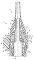
As shown in FIG. 1, an endoscope 1 includes an
挿入部2は、操作部3に対して、挿入部2の長手方向に対して軸周りに回転可能である。操作部3は、挿入部2の後述する湾曲部7の方向を変位させる操作を行う。コネクタ部5は、図示しない光源装置及び図示しないカメラコントロールユニットに接続される。 The
[挿入部2]
挿入部2は、先端部と基端部6aとを有し、この基端部6aが操作部3側に連結されている長尺の可撓管部6と、可撓管部6の先端部と連結し、例えば2方向に湾曲可能な湾曲部7と、湾曲部7の先端部と連結する硬質な先端硬性部8とを有する。2方向は、例えば上下方向であるUP方向とDOWN方向とを示す。[Insertion part 2]
The
先端硬性部8は、図示しない観察光学系と、図示しない照明光学系と、図示しない処置具挿通チャンネルの先端開口部と、図示しない送気送水ノズルとを有する。 The distal rigid portion 8 includes an observation optical system (not shown), an illumination optical system (not shown), a distal opening of a treatment instrument insertion channel (not shown), and an air / water supply nozzle (not shown).
可撓管部6の基端部6aは、可撓管部6と操作部3との連結構造を座屈から保護する折れ止め部材20を有している。このため折れ止め部材20は、弾力性を有している例えばゴム製である。 The
[操作部3]
操作部3は、湾曲部7を操作する湾曲操作レバー9を有している。また操作部3は、操作部3の内部に配設され、湾曲操作レバー9の操作に連動して図示しない湾曲操作ワイヤを牽引する湾曲操作機構を有している。湾曲操作ワイヤの基端部は湾曲操作機構と接続し、湾曲操作ワイヤの先端部は挿入部2を挿通し先端硬性部8と接続している。湾曲操作レバー9の操作に連動して、湾曲操作機構は駆動する。これにより図示しない湾曲操作ワイヤが牽引され、湾曲部7が2方向に湾曲する。そして挿入部2は、目的部位に向かって湾曲する。[Operation unit 3]
The operation unit 3 includes a
操作部3は、図示しない処置具挿通チャンネルに連結された処置具挿入部10と、各種の操作スイッチ11とを有している。 The operation unit 3 includes a treatment
また操作部3は、挿入部2が操作部3に対して回転する際の指標となる目印13を有している。 The operation unit 3 also has a
[挿入部2と操作部3との連結回転構造]
図2に示すように、基端部6aは、硬部材である例えば金属製の可撓管部口金31を有している。可撓管部口金31は、例えば円筒状を有している。可撓管部口金31は、基端部6aと一体となるように、基端部6aに嵌め込まれている。基端部6aの外周面と可撓管部口金31の内周面とは、互いに密着している。
また図2に示すように、操作部3の先端部は、硬部材である例えば金属製の操作部口金41を有している。操作部口金41は、例えば円筒状を有している。操作部口金41は、操作部3の先端部と一体となるように操作部3の先端部に嵌め込まれている。操作部3の先端部の内周面と操作部口金41の外周面とは、互いに密着している。操作部口金41は、例えば円筒状の固定部材17bに挿入され、固定部材17bに固定されている。固定部材17bは、目印13を有している。[Connecting and rotating structure of
As shown in FIG. 2, the
As shown in FIG. 2, the distal end portion of the operation unit 3 includes a metal
可撓管部口金31は、操作部口金41に対して挿入部2の長手方向の軸周りに回転可能に内挿されている。これにより挿入部2(可撓管部6)は、操作部3に対して、軸周りに回転可能に連結する。 The
なお図1と図2とに示すように、内視鏡1は、挿入部2の長手方向において折れ止め部材20の基端部と操作部3の先端部(目印13)との間に配設されている回転操作部である回転ダイアル15と回転ダイアル15を支持する支持部材17aをさらに有している。回転ダイアル15は、リング形状の支持部材17aの外周面を覆うように支持部材17aの外周面に固定されている。この支持部材17aは、支持部材17aの内周面可撓管部口金31の外周面を覆うように、ピン19によって可撓管部口金31に固定されている。このため回転ダイアル15は、支持部材17aとピン19とを介して、可撓管部口金31と連結している。回転ダイアル15は、支持部材17aとピン19と可撓管部口金31とを介して、挿入部2を操作部3に対して周方方向に回転させるために、操作される。このとき、回転ダイアル15は、挿入部2と支持部材17aと可撓管部口金31と折れ止め部材20と共に回転する。またこのとき上述した目印13が回転ダイアル15の回転の指標となる。 As shown in FIGS. 1 and 2, the endoscope 1 is disposed between the proximal end portion of the
このような挿入部2と回転ダイアル15と支持部材17aと折れ止め部材20と可撓管部口金31とは回転部材となり、操作部3と目印13と固定部材17bと操作部口金41とは固定部材となる。 The
[水密確保部材51・回転力量制御部材53]
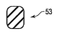
図2に示すように、内視鏡1は、固定部材側と回転部材側との間、つまり挿入部2と操作部3との間の水密を確保する水密確保部材51と、挿入部2が操作部3に対して回転する際に挿入部2に摩擦抵抗を付加し、挿入部2が回転する際の挿入部2の回転力量も制御している回転力量制御部材53とを有している。水密確保部材51と回転力量制御部材53とは、挿入部2の径方向において、固定部材側と回転部材側との間に配設される。言い換えると、水密確保部材51と回転力量制御部材53とは、挿入部2の基端部側(可撓管部口金31)と操作部3の先端部側(操作部口金41)とによって挟まれる。水密確保部材51と回転力量制御部材53とは、別体である。[
As shown in FIG. 2, the endoscope 1 includes a water-
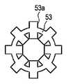
詳細には、可撓管部口金31は、可撓管部口金31の外周面に対して凹設されている凹部33を複数有している。凹部33において、少なくとも1つの凹部33aは例えば固定部材である操作部口金41の内周面と対向しており、また少なくとも1つの凹部33cは例えば回転部材である支持部材17aの内周面と対向している。凹部33aは、複数配設されていてもよい。凹部33a,33cは、可撓管部口金31の周方向に沿ってリング形状に形成されている。つまり、凹部33a,33cは、可撓管部口金31の周方向に沿って可撓管部口金31の外周面の全周に渡って配設されている。凹部33a,33cの断面は、例えば正四角形状を有している。凹部33a,33cは、可撓管部口金31の軸方向に沿って所望な間隔離れてずれて配設されている。凹部33aは、凹部33cよりも操作部3側に配設されている。 Specifically, the
回転力量制御部材53は、凹部33aと同じ形状を有しており、リング形状を有している。回転力量制御部材53の断面は、例えば正四角形状を有している。回転力量制御部材53は、凹部33aに埋設されている。そして回転力量制御部材53は、可撓管部口金31の外周面、つまり凹部33a全体と、操作部口金41の内周面とに密着している。このように回転力量制御部材53は、挿入部2の径方向において、連結している挿入部2の基端部側(可撓管部口金31)と操作部3の先端部側(操作部口金41)との間に配設されている。また回転力量制御部材53は、連結している挿入部2の基端部側(可撓管部口金31の外周面)と操作部3の先端部側(操作部口金41の内周面)とに密着している。 The rotational force
凹部33aが複数配設されていれば、回転力量制御部材53は凹部33aに対応するように複数配設される。 If a plurality of
また水密確保部材51は、凹部33cと同じ形状を有しており、リング形状を有している。水密確保部材51の断面は、例えば正四角形状を有している。水密確保部材51は、凹部33cに埋設されている。水密確保部材51は、可撓管部口金31を可撓管部口金31の外周面側から可撓管部口金31の内周面側に向かって締め付けている。この場合、水密確保部材51は、挿入部2の径方向において、連結している挿入部2の基端部側(可撓管部口金31)と支持部材17aとの間に配設されている。また水密確保部材51は、連結している挿入部2の基端部側(可撓管部口金31の外周面)と支持部材17aの内周面とに密着している。また水密確保部材51は、挿入部2の径方向において、例えば操作部3と操作部口金41との間や、操作部3に固定されている固定部材17bと回転ダイアル15との間にも配設されている。この場合も、上記同様に水密確保部材51は、操作部3と操作部口金41とに密着し、操作部3に固定されている固定部材17bと回転ダイアル15とに密着している。 Further, the water-
水密確保部材51は、例えばOリングやゴム部材である。 The water-
回転力量制御部材53は、水密確保部材51とは異なる位置に配設されている。詳細には、回転力量制御部材53は、水密確保部材51とは軸方向に沿って所望な間隔離れてずれて配設されている。回転力量制御部材53は、少なくとも、連結部である可撓管部口金31と操作部口金41とにおいて配設されている。例えば回転力量制御部材53は、回転力量制御部材53の摩擦力によって、挿入部2が回転する際の挿入部2の回転力量を制御している。回転力量制御部材53は、挿入部2の回転力量が例えば略1Ncm以上略30Ncm以下となるように、挿入部2の回転力量を制御している。また回転力量制御部材53は、可撓管部口金31の外周面、つまり凹部33a全体と、操作部口金41の内周面とに密着している。このように回転力量制御部材53は、挿入部2の径方向において、連結している挿入部2の基端部側(可撓管部口金31)と操作部3の先端部側(操作部口金41)との間に配設されている。また回転力量制御部材53は、連結している挿入部2の基端部側(可撓管部口金31)と操作部3の先端部側(操作部口金41)とに密着している。 The rotational force
また回転力量制御部材53は、可撓管部口金31を外周面側から締め付けている。このとき凹部33a全体と操作部口金41の内周面とに密着している回転力量制御部材53の表面は、例えば平面形状を有している。このような回転力量制御部材53は、例えばOリングやゴム部材である。 The rotational force
また回転力量制御部材53は、水密確保部材51によって水密が確保された内部に配設されている。また凹部33aと、凹部33aに配設される回転力量制御部材53と、水密確保部材51とは、回転ダイアル15などの外装体側ではなく、外力などの外部からの負荷が掛からない位置、例えば可撓管部口金31といった内部部材側、つまり内視鏡1の内部に配設されている。 Further, the rotational
なお挿入部2の基端部側(可撓管部口金31)を締め付ける回転力量制御部材53において、この回転力量制御部材53の摩擦力は、水密確保部材51の摩擦力よりも大きい。この回転力量制御部材53の摩擦力は、例えば、可撓管部口金31を締め付ける締め付け力と、可撓管部口金31を締め付けることで生じる摩擦力と、回転力量制御部材53が潰れることで生じる摩擦力とを含んでいる。この点は水密確保部材51の摩擦力についても同様である。また回転力量制御部材53と水密確保部材51とは、例えば、樹脂またはシリコーンによって形成されている。 In the rotational force
[動作方法]
次に本実施形態の動作方法について説明する。
回転ダイアル15が把持され回転すると、挿入部2は操作部3に対して挿入部2の軸周りに回転する。このとき、回転力量制御部材53は、挿入部2に摩擦抵抗を付加し、挿入部2の回転力量を制御する。回転力量制御部材53と水密確保部材51とは互いに異なる位置に配設されているために、回転力量制御部材53が挿入部2の回転力量を制御しても、水密確保部材51は、回転力量制御部材53に影響することなく水密を確保する。つまり、回転力量制御部材53と水密確保部材51とは別部材であり互いに異なる位置に配設されているために、回転力量制御部材53が磨耗しても、水密は確保される。このように水密の確保と、摩擦抵抗の付加(回転力量の制御)とは、両立される。[Operation method]
Next, the operation method of this embodiment will be described.
When the
なお回転力量制御部材53は、挿入部2の径方向において、可撓管部口金31と操作部口金41との間に配設され、可撓管部口金31と操作部口金41とに密着している。よって回転力量制御部材53は、摩擦力を無駄なく挿入部2に伝達し、挿入部2の回転力量を制御する。 The rotational force
また回転力量制御部材53は、水密確保部材51によって水密を確保された部分に配設されている。よって回転力量制御部材53は、水密確保部材51によって水密を確保された状態で挿入部2の回転力量を制御する。また回転力量制御部材53は、外力などの外部からの負荷が掛からない位置に配設されている。よって回転力量制御部材53は、負荷の影響を受けることなく挿入部2の回転力量を制御する。 Further, the rotational force
また凹部33a全体と操作部口金41の内周面とに密着している回転力量制御部材53の表面は、例えば平面形状を有している。よって回転力量制御部材53はこれらに無駄なく密着する。 Further, the surface of the rotational
回転力量制御部材53の摩擦力は、水密確保部材51の摩擦力よりも大きい。よって、挿入部2の回転力量が制御されつつ、つまり挿入部2が操作部3に対して回転しつつ、水密が確保される。 The frictional force of the rotational
また水密確保部材51は、操作部3に固定されている固定部材17bと挿入部2に固定されている固定ダイアル15との間に配設され、操作部3に固定されている固定部材17bと挿入部2に固定されている固定ダイアル15とに密着している。よって水密確保部材51は、挿入部2と操作部3との間において水密を正確に確保する。 The water-
[効果]
このように本実施形態では、回転力量制御部材53と水密確保部材51とが異なる位置に配設されることで、水密確保部材51によって回転力量制御部材53の影響をうけることなく水密を確実に確保でき、同時に、確実に摩擦抵抗を付加(回転力量の制御)できる。つまり本実施形態では、水密の確保と、摩擦抵抗の付加(回転力量の制御)とを容易に両立できる。[effect]
As described above, in the present embodiment, the rotational force
また本実施形態では、回転力量制御部材53は、挿入部2の径方向において、可撓管部口金31と操作部口金41との間に配設され、可撓管部口金31と操作部口金41とに密着している。これにより本実施形態では、摩擦力を無駄なく挿入部2に伝達でき、挿入部2の回転力量を制御できる。 In the present embodiment, the rotational force
また本実施形態では、回転力量制御部材53は、水密確保部材51によって水密を確保された部分に配設される。これにより本実施形態では、水密確保部材51によって水密を確保された状態で挿入部2の回転力量を制御できる。また本実施形態では、回転力量制御部材53は、外力などの外部からの負荷が掛からない位置に配設される。これにより本実施形態では、負荷の影響を受けることなく挿入部2の回転力量を制御できる。 In the present embodiment, the rotational
また本実施形態では、凹部33a全体と操作部口金41の内周面とに密着している回転力量制御部材53の表面は、例えば平面形状を有している。これにより本実施形態では、回転力量制御部材53をこれらに無駄なく密着させることができる。 In the present embodiment, the surface of the rotational
また本実施形態では、回転力量制御部材53の摩擦力は水密確保部材51の摩擦力よりも大きい。これにより本実施形態では、挿入部2の回転力量を制御しつつ、つまり挿入部2が操作部3に対して回転しつつ、水密を確保できる。 In the present embodiment, the frictional force of the rotational
また本実施形態では、水密確保部材51は、操作部3に固定されている固定部材17bと挿入部2に固定されている固定ダイアル15との間に配設され、操作部3に固定されている固定部材17bと挿入部2に固定されている固定ダイアル15とに密着する。これにより本実施形態では、挿入部2と操作部3との間において水密を確実に確保できる。 In the present embodiment, the water-
また本実施形態では、回転力量制御部材53は、挿入部2の回転力量が例えば略1Ncm以上略30Ncm以下となるように、挿入部2の回転力量を制御している。これにより本実施形態では、挿入部2が使用されている際に挿入部2が使用者の意図しないタイミングで勝手に回転することを防止でき、使用者が挿入部2を回転させやすい力量に回転力量を設定できる。このように本実施形態では、挿入部2の使い勝手を向上できる。 In this embodiment, the rotational force
なお回転力量制御部材53は、挿入部2の回転力量を制御できればよい。このため回転力量制御部材53は、図3に示すように、例えば、目印13と回転ダイアル15との間や、操作部口金41と可撓管部口金31との間や、支持部材17aと固定部材17bとの間や、操作部口金41と支持部材17aとの間に配設されていてもよい。 The rotational force
また回転力量制御部材53の断面の形状は、特に限定される必要は無い。回転力量制御部材53の断面は、図4Aに示すようにひし形形状と、図4Bに示すように円形形状と、図4Cに示すように四隅に円弧を有する矩形形状と、図4Dに示すように矩形形状との少なくとも1つを有していてもよい。 Further, the shape of the cross section of the rotational
また回転力量制御部材53の表面53aは、平面形状に限定する必要は無い。表面53aは、図5Aに示すように表面53aの先端が尖った形状と、図5Bに示すように表面53aの先端が円弧形状と、図5Cに示すように凸凹形状との少なくとも1つを有していても良い。また、図5Cに示す回転力量制御部材53において、回転力量制御部材53の軸方向において、回転力量制御部材53の基端部側から回転力量制御部材53の先端部側に向かって、凸凹の大きさが小さくなっていっても良い。また回転力量制御部材53の表面が密着する凹部33a全体と操作部口金41の内周面とは、凸凹形状であっても良い。これにより、本実施形態では、挿入部2の回転力量を制御できる。 Further, the
また、回転力量制御部材53の表面53aは、例えば、フッ素コートとDLCコートとのいずれかによって、コーティングされていてもよい。 Further, the
また凹部33は、可撓管部口金31の外周面と対向するように、操作部口金41の内周面に配設されていても良い。 The concave portion 33 may be disposed on the inner peripheral surface of the
また回転力量制御部材53は、挿入部2と操作部3との導通を安定させるために、例えば導通性を有していてもよい。 Further, the rotational force
本発明は、上記実施形態そのままに限定されるものではなく、実施段階ではその要旨を逸脱しない範囲で構成要素を変形して具体化できる。また、上記実施形態に開示されている複数の構成要素の適宜な組み合せにより種々の発明を形成できる。 The present invention is not limited to the above-described embodiment as it is, and can be embodied by modifying the constituent elements without departing from the scope of the invention in the implementation stage. Further, various inventions can be formed by appropriately combining a plurality of constituent elements disclosed in the embodiment.
Claims (10)
Translated fromJapanese前記挿入部が前記挿入部の長手方向に対して軸周りに回転するように前記挿入部の基端部と連結する先端部を有し、前記挿入部を操作する操作部と、
前記操作部の前記先端部に嵌め込まれている操作部口金部と、
前記挿入部の前記基端部に嵌め込まれており、前記挿入部が前記操作部に対して前記軸周りに回転可能に連結するように前記操作部口金部に対して前記軸回りに回転可能に直接内挿及び連結している挿入部口金部と、
前記挿入部口金部と連結し、前記挿入部口金部と共に前記軸回りに回転可能であり、前記挿入部口金部を介して前記挿入部を前記操作部に対して前記軸回りに回転させるために操作される回転操作部と、
前記挿入部と前記操作部との間の水密を確保する水密確保部材と、
前記水密確保部材とは異なる位置に配設され、互いに連結している前記操作部口金部と前記挿入部口金部とにおいて前記挿入部口金部と前記操作部口金部とに密着するように前記挿入部の径方向において前記操作部口金部と前記挿入部口金部との間に配設され、前記回転操作部が前記挿入部口金部と共に前記軸回りに回転することによって前記挿入部が前記操作部に対して回転する際に前記挿入部に前記軸回り方向の摩擦抵抗を付加し、前記挿入部が回転する際の前記挿入部の回転力量を制御する回転力量制御部材と、
を具備する内視鏡。An insertion part to be inserted into the body cavity;
An operating portion for operating the insertion portion, having a distal end portion connected to a proximal end portion of the insertion portion so that the insertion portion rotates about an axis with respect to a longitudinal direction of the insertion portion;
An operating portionbase fitted into the distal end of the operating portion;
The insertion portion is fitted into the base end portion, and the insertion portion is rotatable about the axis relative to the operation portionbase so that the insertion portion is rotatably connected to the operation portion around the axis. An insertionbase that isdirectly inserted and connected, and
In order to connect with the insertion part base part and rotate around the axis together with the insertion part base part, and to rotate the insertion part around the axis with respect to the operation part via the insertion part base part A rotary operation unit to be operated;
A water-tightness securing member that secures watertightness between the insertion part and the operation part;
Wherein disposed at a position different from the watertight securing member, said insert so as to be in close contact with said insertion portionconnecter portion and the operation portionconnecter unit in said operation portionconnecter portion and the insertion portionconnecter portion being connected to each other The insertion portion is disposed between the operation portionbase portion and the insertion portionbase portion in the radial direction of the portion, and therotation operation portion rotates about the axis together with the insertion portion base portion so that the insertion portion becomes the operation portion. A rotational force amount control member that adds a frictional resistance in the direction around the axis to the insertion portion when rotating relative to the insertion portion, and controls a rotational force amount of the insertion portion when the insertion portion rotates;
An endoscope comprising:
前記回転力量制御部材の摩擦力は、前記水密確保部材の摩擦力よりも大きい請求項1乃至請求項3のいずれかに記載の内視鏡。In the water-tightness securing member that tightens the base end side of the insertion part, and the rotational force control member that tightens the base end side of the insertion part,
The endoscope according to any one of claims 1 to 3, wherein a frictional force of the rotational force control member is larger than a frictional force of the watertightness securing member.
Priority Applications (1)
| Application Number | Priority Date | Filing Date | Title |
|---|---|---|---|
| JP2012555233AJP5315467B2 (en) | 2011-06-01 | 2012-02-16 | Endoscope |
Applications Claiming Priority (4)
| Application Number | Priority Date | Filing Date | Title |
|---|---|---|---|
| JP2011123656 | 2011-06-01 | ||
| JP2011123656 | 2011-06-01 | ||
| JP2012555233AJP5315467B2 (en) | 2011-06-01 | 2012-02-16 | Endoscope |
| PCT/JP2012/053697WO2012164978A1 (en) | 2011-06-01 | 2012-02-16 | Endoscope |
Publications (2)
| Publication Number | Publication Date |
|---|---|
| JP5315467B2true JP5315467B2 (en) | 2013-10-16 |
| JPWO2012164978A1 JPWO2012164978A1 (en) | 2015-02-23 |
Family
ID=47258846
Family Applications (1)
| Application Number | Title | Priority Date | Filing Date |
|---|---|---|---|
| JP2012555233AActiveJP5315467B2 (en) | 2011-06-01 | 2012-02-16 | Endoscope |
Country Status (5)
| Country | Link |
|---|---|
| US (1) | US9192283B2 (en) |
| EP (1) | EP2716203B1 (en) |
| JP (1) | JP5315467B2 (en) |
| CN (1) | CN103429135B (en) |
| WO (1) | WO2012164978A1 (en) |
Families Citing this family (17)
| Publication number | Priority date | Publication date | Assignee | Title |
|---|---|---|---|---|
| JP6203132B2 (en)* | 2014-06-17 | 2017-09-27 | オリンパス株式会社 | Guide device and surgical system |
| CN104274147B (en)* | 2014-09-24 | 2016-01-06 | 杭州康基医疗器械有限公司 | The dichotomous handle of medical apparatus and instruments |
| WO2016137838A1 (en) | 2015-02-23 | 2016-09-01 | Xiaolong Ouyang | Handheld surgical endoscope |
| US10278563B2 (en) | 2015-02-23 | 2019-05-07 | Uroviu Corp. | Handheld surgical endoscope with detachable cannula |
| US10869592B2 (en) | 2015-02-23 | 2020-12-22 | Uroviu Corp. | Handheld surgical endoscope |
| EP3399899B1 (en)* | 2016-01-05 | 2021-03-31 | Uroviu Corp. | Handheld endoscope |
| US11684248B2 (en) | 2017-09-25 | 2023-06-27 | Micronvision Corp. | Endoscopy/stereo colposcopy medical instrument |
| US11832797B2 (en) | 2016-09-25 | 2023-12-05 | Micronvision Corp. | Endoscopic fluorescence imaging |
| WO2018163410A1 (en)* | 2017-03-10 | 2018-09-13 | オリンパス株式会社 | Guide wire gripping unit |
| US11771304B1 (en) | 2020-11-12 | 2023-10-03 | Micronvision Corp. | Minimally invasive endoscope |
| US12268358B2 (en) | 2019-12-05 | 2025-04-08 | Uroviu Corp. | Portable endoscope with side-mountable disposable portion |
| US11980342B2 (en) | 2020-11-12 | 2024-05-14 | Micronvision Corp. | Minimally invasive endoscope |
| CN109893209B (en)* | 2017-11-17 | 2022-11-15 | 吉鲁斯·阿克米有限责任公司 | Coated endoscopic probe |
| EP4003138A4 (en) | 2019-07-25 | 2023-08-30 | Uroviu Corp. | DISPOSABLE ENDOSCOPY NEEDLE WITH INTEGRATED GRIPPER |
| KR20220137044A (en)* | 2020-02-04 | 2022-10-11 | 보스톤 싸이엔티픽 싸이메드 인코포레이티드 | Rotatable Medical Devices |
| JP7329680B2 (en)* | 2020-03-27 | 2023-08-18 | 富士フイルム株式会社 | Endoscope |
| JP2024034322A (en) | 2022-08-31 | 2024-03-13 | Hoya株式会社 | Endoscope |
Citations (6)
| Publication number | Priority date | Publication date | Assignee | Title |
|---|---|---|---|---|
| JPH0326965B2 (en)* | 1986-11-11 | 1991-04-12 | Fuji Photo Optical Co Ltd | |
| US6099467A (en)* | 1998-03-27 | 2000-08-08 | Karl Storz Gmbh & Co. Kg | Device for positioning components within endoscopic systems |
| JP2002315750A (en)* | 2001-03-14 | 2002-10-29 | Ge Medical Systems Global Technology Co Llc | Trasesophageal ultrasonic probe having rotary endoscope shaft |
| JP2004209283A (en)* | 2004-04-05 | 2004-07-29 | Olympus Corp | Electronic endoscope |
| JP2005124632A (en)* | 2003-10-21 | 2005-05-19 | Olympus Corp | Endoscope |
| JP2007236543A (en)* | 2006-03-07 | 2007-09-20 | Olympus Medical Systems Corp | Endoscope |
Family Cites Families (1)
| Publication number | Priority date | Publication date | Assignee | Title |
|---|---|---|---|---|
| JP2004305413A (en)* | 2003-04-07 | 2004-11-04 | Pentax Corp | Flexible endoscope |
- 2012
- 2012-02-16JPJP2012555233Apatent/JP5315467B2/enactiveActive
- 2012-02-16EPEP12793271.3Apatent/EP2716203B1/ennot_activeNot-in-force
- 2012-02-16WOPCT/JP2012/053697patent/WO2012164978A1/enactiveApplication Filing
- 2012-02-16CNCN201280011588.XApatent/CN103429135B/enactiveActive
- 2012-12-12USUS13/712,202patent/US9192283B2/enactiveActive
Patent Citations (6)
| Publication number | Priority date | Publication date | Assignee | Title |
|---|---|---|---|---|
| JPH0326965B2 (en)* | 1986-11-11 | 1991-04-12 | Fuji Photo Optical Co Ltd | |
| US6099467A (en)* | 1998-03-27 | 2000-08-08 | Karl Storz Gmbh & Co. Kg | Device for positioning components within endoscopic systems |
| JP2002315750A (en)* | 2001-03-14 | 2002-10-29 | Ge Medical Systems Global Technology Co Llc | Trasesophageal ultrasonic probe having rotary endoscope shaft |
| JP2005124632A (en)* | 2003-10-21 | 2005-05-19 | Olympus Corp | Endoscope |
| JP2004209283A (en)* | 2004-04-05 | 2004-07-29 | Olympus Corp | Electronic endoscope |
| JP2007236543A (en)* | 2006-03-07 | 2007-09-20 | Olympus Medical Systems Corp | Endoscope |
Also Published As
| Publication number | Publication date |
|---|---|
| US9192283B2 (en) | 2015-11-24 |
| EP2716203A1 (en) | 2014-04-09 |
| EP2716203B1 (en) | 2018-04-04 |
| CN103429135B (en) | 2016-03-16 |
| EP2716203A4 (en) | 2014-10-29 |
| CN103429135A (en) | 2013-12-04 |
| US20130150672A1 (en) | 2013-06-13 |
| WO2012164978A1 (en) | 2012-12-06 |
| JPWO2012164978A1 (en) | 2015-02-23 |
Similar Documents
| Publication | Publication Date | Title |
|---|---|---|
| JP5315467B2 (en) | Endoscope | |
| JP4615906B2 (en) | Endoscope and endoscope bending operation auxiliary member | |
| JP5622970B1 (en) | Endoscope | |
| CN109310276B (en) | Bending operation mechanism of endoscope | |
| JP5696131B2 (en) | Endoscope push button device | |
| CN114947693A (en) | Locking switching device and its endoscope | |
| JPWO2013145803A1 (en) | Insertion device, rotating cylindrical member and drive unit | |
| JP2010142254A (en) | Coupling structure between insertion section and operation section of endoscope | |
| JP4177020B2 (en) | Endoscope | |
| JP5186223B2 (en) | Endoscope bending operation device | |
| JP2009285304A (en) | Endoscope | |
| JP5802866B2 (en) | Insertion device | |
| WO2015050062A1 (en) | Introduced device | |
| JP5284917B2 (en) | Endoscope | |
| JP2007298815A (en) | Endoscopic device and method for manufacturing the same | |
| JP6407482B2 (en) | Advancement / retraction aid for treatment tool, endoscope system | |
| JP2024034322A (en) | Endoscope | |
| JP7698406B2 (en) | Endoscopy | |
| JP2015009050A (en) | Endoscope system | |
| JP2010088639A (en) | Treatment instrument for endoscope | |
| JP6042796B2 (en) | Insertion equipment | |
| JP2005211460A (en) | Endoscope | |
| JP4483999B2 (en) | Universal cord connection structure of endoscope | |
| CN109310275B (en) | Bending operation mechanism of medical instrument | |
| JP6042795B2 (en) | Insertion equipment |
Legal Events
| Date | Code | Title | Description |
|---|---|---|---|
| TRDD | Decision of grant or rejection written | ||
| A01 | Written decision to grant a patent or to grant a registration (utility model) | Free format text:JAPANESE INTERMEDIATE CODE: A01 Effective date:20130625 | |
| A61 | First payment of annual fees (during grant procedure) | Free format text:JAPANESE INTERMEDIATE CODE: A61 Effective date:20130708 | |
| R151 | Written notification of patent or utility model registration | Ref document number:5315467 Country of ref document:JP Free format text:JAPANESE INTERMEDIATE CODE: R151 | |
| S111 | Request for change of ownership or part of ownership | Free format text:JAPANESE INTERMEDIATE CODE: R313111 | |
| R350 | Written notification of registration of transfer | Free format text:JAPANESE INTERMEDIATE CODE: R350 | |
| S531 | Written request for registration of change of domicile | Free format text:JAPANESE INTERMEDIATE CODE: R313531 | |
| R350 | Written notification of registration of transfer | Free format text:JAPANESE INTERMEDIATE CODE: R350 | |
| R250 | Receipt of annual fees | Free format text:JAPANESE INTERMEDIATE CODE: R250 | |
| R250 | Receipt of annual fees | Free format text:JAPANESE INTERMEDIATE CODE: R250 | |
| R250 | Receipt of annual fees | Free format text:JAPANESE INTERMEDIATE CODE: R250 | |
| R250 | Receipt of annual fees | Free format text:JAPANESE INTERMEDIATE CODE: R250 | |
| R250 | Receipt of annual fees | Free format text:JAPANESE INTERMEDIATE CODE: R250 | |
| R250 | Receipt of annual fees | Free format text:JAPANESE INTERMEDIATE CODE: R250 | |
| R250 | Receipt of annual fees | Free format text:JAPANESE INTERMEDIATE CODE: R250 |