JP5314065B2 - Toilet roll product manufacturing method and toilet roll product - Google Patents
Toilet roll product manufacturing method and toilet roll productDownload PDFInfo
- Publication number
- JP5314065B2 JP5314065B2JP2011036484AJP2011036484AJP5314065B2JP 5314065 B2JP5314065 B2JP 5314065B2JP 2011036484 AJP2011036484 AJP 2011036484AJP 2011036484 AJP2011036484 AJP 2011036484AJP 5314065 B2JP5314065 B2JP 5314065B2
- Authority
- JP
- Japan
- Prior art keywords
- roll
- continuous sheet
- embossing
- chemical solution
- chemical
- Prior art date
- Legal status (The legal status is an assumption and is not a legal conclusion. Google has not performed a legal analysis and makes no representation as to the accuracy of the status listed.)
- Expired - Fee Related
Links
- 238000004519manufacturing processMethods0.000titleclaimsdescription104
- 239000000126substanceSubstances0.000claimsdescription351
- 239000000243solutionSubstances0.000claimsdescription197
- 238000004049embossingMethods0.000claimsdescription189
- 239000007788liquidSubstances0.000claimsdescription91
- 238000000034methodMethods0.000claimsdescription55
- 238000007639printingMethods0.000claimsdescription46
- 238000004804windingMethods0.000claimsdescription46
- 239000008155medical solutionSubstances0.000claimsdescription41
- 238000010030laminatingMethods0.000claimsdescription29
- 238000003475laminationMethods0.000claimsdescription20
- 238000004806packaging method and processMethods0.000claimsdescription17
- 239000004744fabricSubstances0.000claimsdescription15
- 230000032798delaminationEffects0.000claimsdescription8
- 229910052751metalInorganic materials0.000abstractdescription6
- 239000002184metalSubstances0.000abstractdescription6
- 230000015556catabolic processEffects0.000abstractdescription2
- 238000006731degradation reactionMethods0.000abstractdescription2
- 239000003014ion exchange membraneSubstances0.000abstract1
- 230000003647oxidationEffects0.000abstract1
- 238000007254oxidation reactionMethods0.000abstract1
- 239000002344surface layerSubstances0.000abstract1
- 239000000123paperSubstances0.000description148
- 239000000047productSubstances0.000description44
- 238000007774anilox coatingMethods0.000description35
- 238000000576coating methodMethods0.000description33
- 239000007921spraySubstances0.000description33
- 239000011248coating agentSubstances0.000description31
- 238000005507sprayingMethods0.000description31
- 239000010408filmSubstances0.000description26
- 230000008569processEffects0.000description23
- 230000002093peripheral effectEffects0.000description22
- 239000003595mistSubstances0.000description20
- XLYOFNOQVPJJNP-UHFFFAOYSA-NwaterSubstancesOXLYOFNOQVPJJNP-UHFFFAOYSA-N0.000description20
- 239000012530fluidSubstances0.000description16
- 238000012545processingMethods0.000description15
- 230000008901benefitEffects0.000description14
- 238000012546transferMethods0.000description11
- 239000002245particleSubstances0.000description10
- 239000002994raw materialSubstances0.000description10
- JCAQMQLAHNGVPY-UUOKFMHZSA-N[(2r,3s,4r,5r)-3,4-dihydroxy-5-(2,2,4-trioxo-1h-imidazo[4,5-c][1,2,6]thiadiazin-7-yl)oxolan-2-yl]methyl dihydrogen phosphateChemical compoundO[C@@H]1[C@H](O)[C@@H](COP(O)(O)=O)O[C@H]1N1C(NS(=O)(=O)NC2=O)=C2N=C1JCAQMQLAHNGVPY-UUOKFMHZSA-N0.000description8
- 239000003795chemical substances by applicationSubstances0.000description8
- 210000003128headAnatomy0.000description8
- 239000010410layerSubstances0.000description8
- 239000000463materialSubstances0.000description8
- 238000003860storageMethods0.000description8
- 239000000428dustSubstances0.000description7
- 239000003623enhancerSubstances0.000description7
- 230000006870functionEffects0.000description7
- 238000007641inkjet printingMethods0.000description7
- 238000009434installationMethods0.000description7
- DNIAPMSPPWPWGF-UHFFFAOYSA-NPropylene glycolChemical compoundCC(O)CODNIAPMSPPWPWGF-UHFFFAOYSA-N0.000description6
- 238000009795derivationMethods0.000description6
- 238000013461designMethods0.000description6
- 238000002156mixingMethods0.000description6
- 229920002134Carboxymethyl cellulosePolymers0.000description5
- 230000007423decreaseEffects0.000description5
- 229920001971elastomerPolymers0.000description5
- 230000014759maintenance of locationEffects0.000description5
- 230000003020moisturizing effectEffects0.000description5
- 229920005989resinPolymers0.000description5
- 239000011347resinSubstances0.000description5
- PEDCQBHIVMGVHV-UHFFFAOYSA-NGlycerineChemical compoundOCC(O)COPEDCQBHIVMGVHV-UHFFFAOYSA-N0.000description4
- 239000000853adhesiveSubstances0.000description4
- 230000000694effectsEffects0.000description4
- 238000001125extrusionMethods0.000description4
- 230000006872improvementEffects0.000description4
- 229920001684low density polyethylenePolymers0.000description4
- 239000004702low-density polyethyleneSubstances0.000description4
- 229920005862polyolPolymers0.000description4
- 150000003077polyolsChemical class0.000description4
- 239000000843powderSubstances0.000description4
- 238000003825pressingMethods0.000description4
- 239000013055pulp slurrySubstances0.000description4
- 239000002356single layerSubstances0.000description4
- HEMHJVSKTPXQMS-UHFFFAOYSA-MSodium hydroxideChemical compound[OH-].[Na+]HEMHJVSKTPXQMS-UHFFFAOYSA-M0.000description3
- 229910000831SteelInorganic materials0.000description3
- 238000004026adhesive bondingMethods0.000description3
- 230000001070adhesive effectEffects0.000description3
- 239000001768carboxy methyl celluloseSubstances0.000description3
- 238000005520cutting processMethods0.000description3
- 238000009792diffusion processMethods0.000description3
- 238000001035dryingMethods0.000description3
- 239000003292glueSubstances0.000description3
- 238000005304joiningMethods0.000description3
- -1liquid paraffinChemical class0.000description3
- 239000000203mixtureSubstances0.000description3
- 238000000926separation methodMethods0.000description3
- 239000010959steelSubstances0.000description3
- PUPZLCDOIYMWBV-UHFFFAOYSA-N(+/-)-1,3-ButanediolChemical compoundCC(O)CCOPUPZLCDOIYMWBV-UHFFFAOYSA-N0.000description2
- GVJHHUAWPYXKBD-UHFFFAOYSA-N(±)-α-TocopherolChemical compoundOC1=C(C)C(C)=C2OC(CCCC(C)CCCC(C)CCCC(C)C)(C)CCC2=C1CGVJHHUAWPYXKBD-UHFFFAOYSA-N0.000description2
- CIWBSHSKHKDKBQ-JLAZNSOCSA-NAscorbic acidChemical compoundOC[C@H](O)[C@H]1OC(=O)C(O)=C1OCIWBSHSKHKDKBQ-JLAZNSOCSA-N0.000description2
- 102000008186CollagenHuman genes0.000description2
- 108010035532CollagenProteins0.000description2
- 241001391944Commicarpus scandensSpecies0.000description2
- 239000004372Polyvinyl alcoholSubstances0.000description2
- 229920002472StarchPolymers0.000description2
- 238000010521absorption reactionMethods0.000description2
- 230000009471actionEffects0.000description2
- 239000002518antifoaming agentSubstances0.000description2
- 235000010948carboxy methyl celluloseNutrition0.000description2
- 239000008112carboxymethyl-celluloseSubstances0.000description2
- 229940105329carboxymethylcelluloseDrugs0.000description2
- 229920001436collagenPolymers0.000description2
- 238000007766curtain coatingMethods0.000description2
- 230000002950deficientEffects0.000description2
- 238000005516engineering processMethods0.000description2
- 239000000835fiberSubstances0.000description2
- 238000001914filtrationMethods0.000description2
- 239000010419fine particleSubstances0.000description2
- 235000011187glycerolNutrition0.000description2
- 238000009499grossingMethods0.000description2
- 208000014617hemorrhoidDiseases0.000description2
- 229920001903high density polyethylenePolymers0.000description2
- 229920006262high density polyethylene filmPolymers0.000description2
- 239000004700high-density polyethyleneSubstances0.000description2
- 238000002347injectionMethods0.000description2
- 239000007924injectionSubstances0.000description2
- 229920000092linear low density polyethylenePolymers0.000description2
- 239000004707linear low-density polyethyleneSubstances0.000description2
- 239000006210lotionSubstances0.000description2
- 238000012423maintenanceMethods0.000description2
- 230000027939micturitionEffects0.000description2
- 230000004048modificationEffects0.000description2
- 238000012986modificationMethods0.000description2
- 238000012544monitoring processMethods0.000description2
- GLDOVTGHNKAZLK-UHFFFAOYSA-Noctadecan-1-olChemical compoundCCCCCCCCCCCCCCCCCCOGLDOVTGHNKAZLK-UHFFFAOYSA-N0.000description2
- 239000000049pigmentSubstances0.000description2
- 229920002401polyacrylamidePolymers0.000description2
- 229920002451polyvinyl alcoholPolymers0.000description2
- 229960004063propylene glycolDrugs0.000description2
- 150000003839saltsChemical class0.000description2
- 239000007787solidSubstances0.000description2
- 239000008107starchSubstances0.000description2
- 235000019698starchNutrition0.000description2
- 239000000758substrateSubstances0.000description2
- 150000005846sugar alcoholsPolymers0.000description2
- 239000004094surface-active agentSubstances0.000description2
- 238000010998test methodMethods0.000description2
- 238000011144upstream manufacturingMethods0.000description2
- HDTRYLNUVZCQOY-UHFFFAOYSA-Nα-D-glucopyranosyl-α-D-glucopyranosideNatural productsOC1C(O)C(O)C(CO)OC1OC1C(O)C(O)C(O)C(CO)O1HDTRYLNUVZCQOY-UHFFFAOYSA-N0.000description1
- KIUKXJAPPMFGSW-DNGZLQJQSA-N(2S,3S,4S,5R,6R)-6-[(2S,3R,4R,5S,6R)-3-Acetamido-2-[(2S,3S,4R,5R,6R)-6-[(2R,3R,4R,5S,6R)-3-acetamido-2,5-dihydroxy-6-(hydroxymethyl)oxan-4-yl]oxy-2-carboxy-4,5-dihydroxyoxan-3-yl]oxy-5-hydroxy-6-(hydroxymethyl)oxan-4-yl]oxy-3,4,5-trihydroxyoxane-2-carboxylic acidChemical compoundCC(=O)N[C@H]1[C@H](O)O[C@H](CO)[C@@H](O)[C@@H]1O[C@H]1[C@H](O)[C@@H](O)[C@H](O[C@H]2[C@@H]([C@@H](O[C@H]3[C@@H]([C@@H](O)[C@H](O)[C@H](O3)C(O)=O)O)[C@H](O)[C@@H](CO)O2)NC(C)=O)[C@@H](C(O)=O)O1KIUKXJAPPMFGSW-DNGZLQJQSA-N0.000description1
- ALSTYHKOOCGGFT-KTKRTIGZSA-N(9Z)-octadecen-1-olChemical compoundCCCCCCCC\C=C/CCCCCCCCOALSTYHKOOCGGFT-KTKRTIGZSA-N0.000description1
- 2299400580151,3-butylene glycolDrugs0.000description1
- OWEGMIWEEQEYGQ-UHFFFAOYSA-N100676-05-9Natural productsOC1C(O)C(O)C(CO)OC1OCC1C(O)C(O)C(O)C(OC2C(OC(O)C(O)C2O)CO)O1OWEGMIWEEQEYGQ-UHFFFAOYSA-N0.000description1
- MIDXCONKKJTLDX-UHFFFAOYSA-N3,5-dimethylcyclopentane-1,2-dioneChemical compoundCC1CC(C)C(=O)C1=OMIDXCONKKJTLDX-UHFFFAOYSA-N0.000description1
- YDNKGFDKKRUKPY-JHOUSYSJSA-NC16 ceramideNatural productsCCCCCCCCCCCCCCCC(=O)N[C@@H](CO)[C@H](O)C=CCCCCCCCCCCCCCYDNKGFDKKRUKPY-JHOUSYSJSA-N0.000description1
- FBPFZTCFMRRESA-FSIIMWSLSA-ND-GlucitolNatural productsOC[C@H](O)[C@H](O)[C@@H](O)[C@H](O)COFBPFZTCFMRRESA-FSIIMWSLSA-N0.000description1
- FBPFZTCFMRRESA-KVTDHHQDSA-ND-MannitolChemical compoundOC[C@@H](O)[C@@H](O)[C@H](O)[C@H](O)COFBPFZTCFMRRESA-KVTDHHQDSA-N0.000description1
- ZZZCUOFIHGPKAK-UHFFFAOYSA-ND-erythro-ascorbic acidNatural productsOCC1OC(=O)C(O)=C1OZZZCUOFIHGPKAK-UHFFFAOYSA-N0.000description1
- FBPFZTCFMRRESA-JGWLITMVSA-ND-glucitolChemical compoundOC[C@H](O)[C@@H](O)[C@H](O)[C@H](O)COFBPFZTCFMRRESA-JGWLITMVSA-N0.000description1
- BRLQWZUYTZBJKN-UHFFFAOYSA-NEpichlorohydrinChemical compoundClCC1CO1BRLQWZUYTZBJKN-UHFFFAOYSA-N0.000description1
- 206010016322Feeling abnormalDiseases0.000description1
- WQZGKKKJIJFFOK-GASJEMHNSA-NGlucoseNatural productsOC[C@H]1OC(O)[C@H](O)[C@@H](O)[C@@H]1OWQZGKKKJIJFFOK-GASJEMHNSA-N0.000description1
- 102000011782KeratinsHuman genes0.000description1
- 108010076876KeratinsProteins0.000description1
- GUBGYTABKSRVRQ-PICCSMPSSA-NMaltoseNatural productsO[C@@H]1[C@@H](O)[C@H](O)[C@@H](CO)O[C@@H]1O[C@@H]1[C@@H](CO)OC(O)[C@H](O)[C@H]1OGUBGYTABKSRVRQ-PICCSMPSSA-N0.000description1
- 229930195725MannitolNatural products0.000description1
- 229920000877Melamine resinPolymers0.000description1
- 239000004640Melamine resinSubstances0.000description1
- CRJGESKKUOMBCT-VQTJNVASSA-NN-acetylsphinganineChemical compoundCCCCCCCCCCCCCCC[C@@H](O)[C@H](CO)NC(C)=OCRJGESKKUOMBCT-VQTJNVASSA-N0.000description1
- 239000004952PolyamideSubstances0.000description1
- 239000004698PolyethyleneSubstances0.000description1
- 239000002202Polyethylene glycolSubstances0.000description1
- 239000004743PolypropyleneSubstances0.000description1
- 239000004793PolystyreneSubstances0.000description1
- 229920001131Pulp (paper)Polymers0.000description1
- HDTRYLNUVZCQOY-WSWWMNSNSA-NTrehaloseNatural productsO[C@@H]1[C@@H](O)[C@@H](O)[C@@H](CO)O[C@@H]1O[C@@H]1[C@H](O)[C@@H](O)[C@@H](O)[C@@H](CO)O1HDTRYLNUVZCQOY-WSWWMNSNSA-N0.000description1
- 229920001807Urea-formaldehydePolymers0.000description1
- 229920006311Urethane elastomerPolymers0.000description1
- 229930003268Vitamin CNatural products0.000description1
- 229930003427Vitamin ENatural products0.000description1
- TVXBFESIOXBWNM-UHFFFAOYSA-NXylitolNatural productsOCCC(O)C(O)C(O)CCOTVXBFESIOXBWNM-UHFFFAOYSA-N0.000description1
- HCHKCACWOHOZIP-UHFFFAOYSA-NZincChemical compound[Zn]HCHKCACWOHOZIP-UHFFFAOYSA-N0.000description1
- DPXJVFZANSGRMM-UHFFFAOYSA-Nacetic acid;2,3,4,5,6-pentahydroxyhexanal;sodiumChemical compound[Na].CC(O)=O.OCC(O)C(O)C(O)C(O)C=ODPXJVFZANSGRMM-UHFFFAOYSA-N0.000description1
- 239000002253acidSubstances0.000description1
- 150000001298alcoholsChemical class0.000description1
- HDTRYLNUVZCQOY-LIZSDCNHSA-Nalpha,alpha-trehaloseChemical compoundO[C@@H]1[C@@H](O)[C@H](O)[C@@H](CO)O[C@@H]1O[C@@H]1[C@H](O)[C@@H](O)[C@H](O)[C@@H](CO)O1HDTRYLNUVZCQOY-LIZSDCNHSA-N0.000description1
- 239000003945anionic surfactantSubstances0.000description1
- 239000003429antifungal agentSubstances0.000description1
- 229940121375antifungal agentDrugs0.000description1
- 239000003963antioxidant agentSubstances0.000description1
- 230000003078antioxidant effectEffects0.000description1
- 235000006708antioxidantsNutrition0.000description1
- WQZGKKKJIJFFOK-VFUOTHLCSA-Nbeta-D-glucoseChemical compoundOC[C@H]1O[C@@H](O)[C@H](O)[C@@H](O)[C@@H]1OWQZGKKKJIJFFOK-VFUOTHLCSA-N0.000description1
- GUBGYTABKSRVRQ-QUYVBRFLSA-Nbeta-maltoseChemical compoundOC[C@H]1O[C@H](O[C@H]2[C@H](O)[C@@H](O)[C@H](O)O[C@@H]2CO)[C@H](O)[C@@H](O)[C@@H]1OGUBGYTABKSRVRQ-QUYVBRFLSA-N0.000description1
- 235000019437butane-1,3-diolNutrition0.000description1
- 238000003490calenderingMethods0.000description1
- 235000013736caramelNutrition0.000description1
- 229940084030carboxymethylcellulose calciumDrugs0.000description1
- 239000003093cationic surfactantSubstances0.000description1
- 229940106189ceramideDrugs0.000description1
- ZVEQCJWYRWKARO-UHFFFAOYSA-NceramideNatural productsCCCCCCCCCCCCCCC(O)C(=O)NC(CO)C(O)C=CCCC=C(C)CCCCCCCCCZVEQCJWYRWKARO-UHFFFAOYSA-N0.000description1
- 229960000541cetyl alcoholDrugs0.000description1
- 230000008859changeEffects0.000description1
- XTEGARKTQYYJKE-UHFFFAOYSA-Nchloric acidChemical compoundOCl(=O)=OXTEGARKTQYYJKE-UHFFFAOYSA-N0.000description1
- 229940005991chloric acidDrugs0.000description1
- 238000004140cleaningMethods0.000description1
- 239000000084colloidal systemSubstances0.000description1
- 239000003086colorantSubstances0.000description1
- 238000013329compoundingMethods0.000description1
- 238000011109contaminationMethods0.000description1
- 230000013872defecationEffects0.000description1
- 230000007547defectEffects0.000description1
- 230000001877deodorizing effectEffects0.000description1
- 238000001514detection methodMethods0.000description1
- 229940105990diglycerinDrugs0.000description1
- GPLRAVKSCUXZTP-UHFFFAOYSA-NdiglycerolChemical compoundOCC(O)COCC(O)COGPLRAVKSCUXZTP-UHFFFAOYSA-N0.000description1
- 239000006185dispersionSubstances0.000description1
- 238000009826distributionMethods0.000description1
- 239000013013elastic materialSubstances0.000description1
- 239000003974emollient agentSubstances0.000description1
- 239000003995emulsifying agentSubstances0.000description1
- 238000011156evaluationMethods0.000description1
- 230000029142excretionEffects0.000description1
- 239000000284extractSubstances0.000description1
- 239000012467final productSubstances0.000description1
- 238000007667floatingMethods0.000description1
- 238000005187foamingMethods0.000description1
- 235000011194food seasoning agentNutrition0.000description1
- WIGCFUFOHFEKBI-UHFFFAOYSA-Ngamma-tocopherolNatural productsCC(C)CCCC(C)CCCC(C)CCCC1CCC2C(C)C(O)C(C)C(C)C2O1WIGCFUFOHFEKBI-UHFFFAOYSA-N0.000description1
- 239000003349gelling agentSubstances0.000description1
- 210000004392genitaliaAnatomy0.000description1
- 239000008103glucoseSubstances0.000description1
- 229960005150glycerolDrugs0.000description1
- BXWNKGSJHAJOGX-UHFFFAOYSA-Nhexadecan-1-olChemical compoundCCCCCCCCCCCCCCCCOBXWNKGSJHAJOGX-UHFFFAOYSA-N0.000description1
- 229920002674hyaluronanPolymers0.000description1
- 229960003160hyaluronic acidDrugs0.000description1
- 229920001477hydrophilic polymerPolymers0.000description1
- 239000004615ingredientSubstances0.000description1
- 238000007689inspectionMethods0.000description1
- 230000010354integrationEffects0.000description1
- 239000013067intermediate productSubstances0.000description1
- 229940057995liquid paraffinDrugs0.000description1
- VQHSOMBJVWLPSR-WUJBLJFYSA-NmaltitolChemical compoundOC[C@H](O)[C@@H](O)[C@@H]([C@H](O)CO)O[C@H]1O[C@H](CO)[C@@H](O)[C@H](O)[C@H]1OVQHSOMBJVWLPSR-WUJBLJFYSA-N0.000description1
- 239000000845maltitolSubstances0.000description1
- 235000010449maltitolNutrition0.000description1
- 229940035436maltitolDrugs0.000description1
- 239000000594mannitolSubstances0.000description1
- 235000010355mannitolNutrition0.000description1
- 230000007246mechanismEffects0.000description1
- HEBKCHPVOIAQTA-UHFFFAOYSA-Nmeso ribitolNatural productsOCC(O)C(O)C(O)COHEBKCHPVOIAQTA-UHFFFAOYSA-N0.000description1
- GOQYKNQRPGWPLP-UHFFFAOYSA-Nn-heptadecyl alcoholNatural productsCCCCCCCCCCCCCCCCCOGOQYKNQRPGWPLP-UHFFFAOYSA-N0.000description1
- VVGIYYKRAMHVLU-UHFFFAOYSA-NnewbouldiamideNatural productsCCCCCCCCCCCCCCCCCCCC(O)C(O)C(O)C(CO)NC(=O)CCCCCCCCCCCCCCCCCVVGIYYKRAMHVLU-UHFFFAOYSA-N0.000description1
- 239000004745nonwoven fabricSubstances0.000description1
- 229940055577oleyl alcoholDrugs0.000description1
- XMLQWXUVTXCDDL-UHFFFAOYSA-Noleyl alcoholNatural productsCCCCCCC=CCCCCCCCCCCOXMLQWXUVTXCDDL-UHFFFAOYSA-N0.000description1
- 150000007524organic acidsChemical class0.000description1
- 235000005985organic acidsNutrition0.000description1
- 239000003002pH adjusting agentSubstances0.000description1
- 239000013054paper strength agentSubstances0.000description1
- 239000010893paper wasteSubstances0.000description1
- 239000011087paperboardSubstances0.000description1
- 230000035515penetrationEffects0.000description1
- 239000012466permeateSubstances0.000description1
- 229920002647polyamidePolymers0.000description1
- 229920000768polyaminePolymers0.000description1
- 229920000573polyethylenePolymers0.000description1
- 229920001223polyethylene glycolPolymers0.000description1
- 229920001155polypropylenePolymers0.000description1
- 229920002223polystyrenePolymers0.000description1
- 239000003755preservative agentSubstances0.000description1
- 230000002335preservative effectEffects0.000description1
- 230000002265preventionEffects0.000description1
- 230000001681protective effectEffects0.000description1
- 238000010926purgeMethods0.000description1
- 230000009467reductionEffects0.000description1
- 230000004044responseEffects0.000description1
- 238000005096rolling processMethods0.000description1
- 238000007790scrapingMethods0.000description1
- 230000001953sensory effectEffects0.000description1
- 239000002002slurrySubstances0.000description1
- 235000019812sodium carboxymethyl celluloseNutrition0.000description1
- 229920001027sodium carboxymethylcellulosePolymers0.000description1
- 235000011121sodium hydroxideNutrition0.000description1
- 239000000600sorbitolSubstances0.000description1
- 230000000087stabilizing effectEffects0.000description1
- 229940012831stearyl alcoholDrugs0.000description1
- 235000000346sugarNutrition0.000description1
- 150000008163sugarsChemical class0.000description1
- 230000007704transitionEffects0.000description1
- 238000013022ventingMethods0.000description1
- 229930003231vitaminNatural products0.000description1
- 239000011782vitaminSubstances0.000description1
- 235000013343vitaminNutrition0.000description1
- 229940088594vitaminDrugs0.000description1
- 235000019154vitamin CNutrition0.000description1
- 239000011718vitamin CSubstances0.000description1
- 235000019165vitamin ENutrition0.000description1
- 229940046009vitamin EDrugs0.000description1
- 239000011709vitamin ESubstances0.000description1
- 239000001993waxSubstances0.000description1
- 230000037303wrinklesEffects0.000description1
- 239000000811xylitolSubstances0.000description1
- HEBKCHPVOIAQTA-SCDXWVJYSA-NxylitolChemical compoundOC[C@H](O)[C@@H](O)[C@H](O)COHEBKCHPVOIAQTA-SCDXWVJYSA-N0.000description1
- 235000010447xylitolNutrition0.000description1
- 229960002675xylitolDrugs0.000description1
- 229910052725zincInorganic materials0.000description1
- 239000011701zincSubstances0.000description1
- 239000002888zwitterionic surfactantSubstances0.000description1
Images


Classifications
- B—PERFORMING OPERATIONS; TRANSPORTING
- B31—MAKING ARTICLES OF PAPER, CARDBOARD OR MATERIAL WORKED IN A MANNER ANALOGOUS TO PAPER; WORKING PAPER, CARDBOARD OR MATERIAL WORKED IN A MANNER ANALOGOUS TO PAPER
- B31F—MECHANICAL WORKING OR DEFORMATION OF PAPER, CARDBOARD OR MATERIAL WORKED IN A MANNER ANALOGOUS TO PAPER
- B31F1/00—Mechanical deformation without removing material, e.g. in combination with laminating
- B31F1/07—Embossing, i.e. producing impressions formed by locally deep-drawing, e.g. using rolls provided with complementary profiles
- D—TEXTILES; PAPER
- D21—PAPER-MAKING; PRODUCTION OF CELLULOSE
- D21H—PULP COMPOSITIONS; PREPARATION THEREOF NOT COVERED BY SUBCLASSES D21C OR D21D; IMPREGNATING OR COATING OF PAPER; TREATMENT OF FINISHED PAPER NOT COVERED BY CLASS B31 OR SUBCLASS D21G; PAPER NOT OTHERWISE PROVIDED FOR
- D21H1/00—Paper; Cardboard
- A—HUMAN NECESSITIES
- A47—FURNITURE; DOMESTIC ARTICLES OR APPLIANCES; COFFEE MILLS; SPICE MILLS; SUCTION CLEANERS IN GENERAL
- A47K—SANITARY EQUIPMENT NOT OTHERWISE PROVIDED FOR; TOILET ACCESSORIES
- A47K10/00—Body-drying implements; Toilet paper; Holders therefor
- A47K10/16—Paper towels; Toilet paper; Holders therefor
- A47K10/18—Holders; Receptacles
- A47K10/22—Holders; Receptacles for rolled-up webs
- D—TEXTILES; PAPER
- D21—PAPER-MAKING; PRODUCTION OF CELLULOSE
- D21H—PULP COMPOSITIONS; PREPARATION THEREOF NOT COVERED BY SUBCLASSES D21C OR D21D; IMPREGNATING OR COATING OF PAPER; TREATMENT OF FINISHED PAPER NOT COVERED BY CLASS B31 OR SUBCLASS D21G; PAPER NOT OTHERWISE PROVIDED FOR
- D21H23/00—Processes or apparatus for adding material to the pulp or to the paper
- D21H23/02—Processes or apparatus for adding material to the pulp or to the paper characterised by the manner in which substances are added
- D21H23/22—Addition to the formed paper
- D21H23/46—Pouring or allowing the fluid to flow in a continuous stream on to the surface, the entire stream being carried away by the paper
- D21H23/48—Curtain coaters
- D—TEXTILES; PAPER
- D21—PAPER-MAKING; PRODUCTION OF CELLULOSE
- D21H—PULP COMPOSITIONS; PREPARATION THEREOF NOT COVERED BY SUBCLASSES D21C OR D21D; IMPREGNATING OR COATING OF PAPER; TREATMENT OF FINISHED PAPER NOT COVERED BY CLASS B31 OR SUBCLASS D21G; PAPER NOT OTHERWISE PROVIDED FOR
- D21H27/00—Special paper not otherwise provided for, e.g. made by multi-step processes
- D21H27/002—Tissue paper; Absorbent paper
- D21H27/004—Tissue paper; Absorbent paper characterised by specific parameters
- D21H27/005—Tissue paper; Absorbent paper characterised by specific parameters relating to physical or mechanical properties, e.g. tensile strength, stretch, softness
- A—HUMAN NECESSITIES
- A47—FURNITURE; DOMESTIC ARTICLES OR APPLIANCES; COFFEE MILLS; SPICE MILLS; SUCTION CLEANERS IN GENERAL
- A47K—SANITARY EQUIPMENT NOT OTHERWISE PROVIDED FOR; TOILET ACCESSORIES
- A47K10/00—Body-drying implements; Toilet paper; Holders therefor
- A47K10/16—Paper towels; Toilet paper; Holders therefor
- B—PERFORMING OPERATIONS; TRANSPORTING
- B31—MAKING ARTICLES OF PAPER, CARDBOARD OR MATERIAL WORKED IN A MANNER ANALOGOUS TO PAPER; WORKING PAPER, CARDBOARD OR MATERIAL WORKED IN A MANNER ANALOGOUS TO PAPER
- B31B—MAKING CONTAINERS OF PAPER, CARDBOARD OR MATERIAL WORKED IN A MANNER ANALOGOUS TO PAPER
- B31B70/00—Making flexible containers, e.g. envelopes or bags
- B31B70/006—Controlling; Regulating; Measuring; Safety measures
- B—PERFORMING OPERATIONS; TRANSPORTING
- B31—MAKING ARTICLES OF PAPER, CARDBOARD OR MATERIAL WORKED IN A MANNER ANALOGOUS TO PAPER; WORKING PAPER, CARDBOARD OR MATERIAL WORKED IN A MANNER ANALOGOUS TO PAPER
- B31F—MECHANICAL WORKING OR DEFORMATION OF PAPER, CARDBOARD OR MATERIAL WORKED IN A MANNER ANALOGOUS TO PAPER
- B31F2201/00—Mechanical deformation of paper or cardboard without removing material
- B31F2201/07—Embossing
- B31F2201/0758—Characteristics of the embossed product
- B31F2201/0761—Multi-layered
- B—PERFORMING OPERATIONS; TRANSPORTING
- B65—CONVEYING; PACKING; STORING; HANDLING THIN OR FILAMENTARY MATERIAL
- B65H—HANDLING THIN OR FILAMENTARY MATERIAL, e.g. SHEETS, WEBS, CABLES
- B65H2301/00—Handling processes for sheets or webs
- B65H2301/40—Type of handling process
- B65H2301/41—Winding, unwinding
- B65H2301/414—Winding
- B65H2301/4148—Winding slitting
- B65H2301/41484—Winding slitting slitting roll after winding, i.e. cutting log into individual rolls
- B—PERFORMING OPERATIONS; TRANSPORTING
- B65—CONVEYING; PACKING; STORING; HANDLING THIN OR FILAMENTARY MATERIAL
- B65H—HANDLING THIN OR FILAMENTARY MATERIAL, e.g. SHEETS, WEBS, CABLES
- B65H2701/00—Handled material; Storage means
- B65H2701/10—Handled articles or webs
- B65H2701/17—Nature of material
- B65H2701/176—Cardboard
- B65H2701/1762—Corrugated
- D—TEXTILES; PAPER
- D21—PAPER-MAKING; PRODUCTION OF CELLULOSE
- D21H—PULP COMPOSITIONS; PREPARATION THEREOF NOT COVERED BY SUBCLASSES D21C OR D21D; IMPREGNATING OR COATING OF PAPER; TREATMENT OF FINISHED PAPER NOT COVERED BY CLASS B31 OR SUBCLASS D21G; PAPER NOT OTHERWISE PROVIDED FOR
- D21H27/00—Special paper not otherwise provided for, e.g. made by multi-step processes
- D21H27/30—Multi-ply
- D21H27/40—Multi-ply at least one of the sheets being non-planar, e.g. crêped
- Y—GENERAL TAGGING OF NEW TECHNOLOGICAL DEVELOPMENTS; GENERAL TAGGING OF CROSS-SECTIONAL TECHNOLOGIES SPANNING OVER SEVERAL SECTIONS OF THE IPC; TECHNICAL SUBJECTS COVERED BY FORMER USPC CROSS-REFERENCE ART COLLECTIONS [XRACs] AND DIGESTS
- Y10—TECHNICAL SUBJECTS COVERED BY FORMER USPC
- Y10T—TECHNICAL SUBJECTS COVERED BY FORMER US CLASSIFICATION
- Y10T428/00—Stock material or miscellaneous articles
- Y10T428/15—Sheet, web, or layer weakened to permit separation through thickness
Landscapes
- Engineering & Computer Science (AREA)
- Mechanical Engineering (AREA)
- Health & Medical Sciences (AREA)
- Public Health (AREA)
- Sanitary Thin Papers (AREA)
- Machines For Manufacturing Corrugated Board In Mechanical Paper-Making Processes (AREA)
- Paper (AREA)
Abstract
Description
Translated fromJapanese本発明は、薬液が塗布されたクレープを有するトイレットペーパーを巻取ったトイレットロールを包装してなるトイレットロール製品及びその製造方法に関する。 The present invention relates to a toilet roll product formed by packaging a toilet roll wound with toilet paper having a crepe coated with a chemical solution, and a method for manufacturing the toilet roll product.
トイレットペーパーは、一般的に、連続する帯状のものを紙管と称される管芯に巻取とったトイレットロールの形態とされ、これを複数個包装した状態のトイレットロール製品として市販に供されている。 Toilet paper is generally in the form of a toilet roll in which a continuous strip is wound around a tube core called a paper tube. ing.
上記トイレットペーパーにおいては、需用者は、価格ととともに、保湿性(しっとり感)、柔軟性(柔らかさ感)、表面の滑らかさ性(滑らかさ感)といった点に関心があり、この点において高品質なトイレットペーパーを求める。 In the above toilet paper, consumers are interested in price, moisture retention (moistness), flexibility (softness), and surface smoothness (smoothness). Seeking high quality toilet paper.
また、痔疾患患者等においては、排泄後の清拭作業において強く擦るといった清拭が行ない難い。このためかかる痔疾患患者においては、拭取り性、嵩高性と保湿性、柔軟性、表面の滑らかさ性が高められたトイレットペーパーに極めて関心があり、それらの機能に優れる製品を求める。 In addition, it is difficult for patients with hemorrhoids or the like to perform wiping such as rubbing strongly in the wiping work after excretion. For this reason, patients with such hemorrhoids are extremely interested in toilet paper with improved wiping, bulkiness and moisture retention, flexibility, and surface smoothness, and demand for products that excel in their functions.
また、トイレットペーパーは、排便後のみならず特に女性においては排尿後の清拭用にも用いられ、この女性における排尿後の清拭は敏感な陰部への接触を伴うため、保湿性、柔らかさのあるトイレットペーパーの潜在的需要がある。 In addition, toilet paper is used not only after defecation but also for wiping after urination, especially in women. Since wiping after urination in this woman involves contact with sensitive genital areas, it is moisturizing and soft. There is a potential demand for toilet paper.
ここで、トイレットペーパーの中には、保湿性(しっとり感)、柔軟性(柔らかさ感)、表面の滑らかさ性(滑らかさ感)を高めるべく、かかる各特性を向上させる薬液が付与されたものがある。 Here, in the toilet paper, chemicals that improve each of these properties were applied in order to enhance moisture retention (moist feeling), flexibility (soft feeling), and surface smoothness (smooth feeling). There is something.
しかし、従来の薬液が付与されたトイレットロールは、生産性が極めて悪く、高価でもあり、そのうえ各特性のすべてが十分に向上されたものではなく、需用者の要求を満足するものではなかった。 However, the conventional toilet roll to which the chemical solution is applied is extremely poor in productivity and is expensive, and not all of the characteristics are sufficiently improved, and does not satisfy the demands of consumers. .
このため従来の薬液が付与されたトイレットロール製品は広く普及するに至っていない。 For this reason, the toilet roll product to which the conventional chemical | medical solution was provided has not reached wide spread.
ここで、従来の通常のトイレットロールは、抄紙設備で製造した原反ロールをワインダーに移送し、このワインダーにてトイレットロールの直径にまき直して、トイレットロール幅の複数倍幅以上のログを製造し、その後にかかるログをトイレットロールの幅に裁断してトイレットロールとしている。複数プライの製品を製造する場合にはワインダーにおいて巻き直しの前に複数の原反ロールから巻き出した連続シートを積層するようにしている。 Here, the conventional normal toilet roll is manufactured by transferring the roll roll manufactured by the paper making equipment to the winder, and rolling it to the diameter of the toilet roll with this winder to produce logs that are more than double the width of the toilet roll. Then, the log taken thereafter is cut into the width of the toilet roll to form a toilet roll. In the case of producing a multi-ply product, a continuous sheet unwound from a plurality of original rolls is laminated before being rewound in a winder.
そして、薬液が付与されたトイレットロールの製造方法は、例えば、下記特許文献1〜3に開示されている。 And the manufacturing method of the toilet roll to which the chemical | medical solution was provided is disclosed by the following patent documents 1-3, for example.
特許文献1の技術は、ワインダーにセットした原反ロールからログを製造する際に、スチールラバー方式でエンボスを付与することとし、その凸エンボスロールのエンボス凸部に薬液を付与して原反ロールから巻き出される連続シートに薬液を転写して付与する技術である。 In the technique of
しかし、特許文献1の技術は、エンボス凸部の頂点にのみ薬液を付与して連続シートに薬液を付与することから薬液使用量が少なく、さらにエンボス凹面には薬液が付与されていない部分が生ずるおそれがあり、表面の滑らかさの向上、保湿性の向上が十分なものとならない。さらに、最も紙力が低下する薬液付与時と連続シートに所定圧で挟持するエンボス付与時とが同時であるため断紙が発生しやすく、低速で加工する必要があり生産性を高めがたい。 However, since the technique of
他方、特許文献2の技術は、ワインダーにセットした原反ロールからログを製造する際に、エンボスを付与した後、スプレー方式で薬液を付与する技術である。 On the other hand, the technique of
しかし、特許文献2の技術も薬液付与直後にログとするためログ製造後に紙中への薬液拡散が生じ、クレープの伸びによる紙の伸びによってログの巻きずれ型くずれがし易いという欠点がある。特にログは後に裁断してトイレットロールとなるものであるためログにおいて巻きずれ、型くずれが発生すると不良品のトイレットロールとなり歩留まりも悪化するため生産効率を極めて低下させる要因となる。 However, since the technique of
また、特許文献1と同様に、薬液付与直後にログを製造するため、テンションコントロールが難しく、ミシン目線を付与時の断紙が発生しやすく、連続シートのテンションを低くし、低速で加工せざるを得ず、生産性が高められない。 Further, as in
また、特許文献2の技術では、エンボス後に特にスプレー塗布で薬液を付与するためエンボスの型くずれもしやすい。さらに、ワインダーにてスプレー方式では吐出量が制限されるため、低速加工でないと連続シートへの薬液付与量が少なくなってしまい、生産性が高められない。 Moreover, in the technique of
特許文献3の技術は、トイレットペーパー製品用の原紙としてエンボス加工クレープ紙を得る技術であり、複数の原反ロールから連続シートを巻きだしそれらを重ね合わせた後にそれら積層連続シートに薬液を付与し、さらにスプレーで水を付与して湿紙にした後にエンボスを付与する。そして、再度巻き取りを行なう前に積層された各連続シートの分離を行なうという技術である。 The technology of
しかしながら、引用文献3の技術では、エンボス付与前にスプレーで水を付与するため、薬液或いは水が連続シートに対し十分に浸透する前にエンボス加工がされるため、連続シート表面の浸透していない薬液がエンボスを付与する凸エンボスロールおよび受けロールに付着してしまい、断紙や掃除によるライン停止の要因となり得るため、生産性を高めることができない。 However, in the technique of the cited
また、薬液付与時の紙力の低下の小さい薬液として油性の薬液が知られ、かかる油性の薬液を使用したトイレットロールも知られるが、かかるトイレットロールは表面の滑らかさの改善は十分であるものの保湿性については不十分であり、また、薬液の中でも紙層内に浸透し難い油性の薬液が用いられていることによる。また、このトイレットロールに必要な水解性の点でも難がある。 In addition, an oily chemical solution is known as a chemical solution with a small decrease in paper strength when the chemical solution is applied, and a toilet roll using such an oily chemical solution is also known, but such a toilet roll has sufficient improvement in surface smoothness. This is because the moisturizing property is insufficient, and among the chemical solutions, oily chemical solutions that do not easily penetrate into the paper layer are used. Moreover, there is a difficulty in terms of water decomposability necessary for this toilet roll.
そこで、本発明の主たる課題は、トイレットペーパーに必要な水解性等の性能を十分なものとしつつ、保湿性(しっとり感)、柔軟性(柔らかさ感)、表面の滑らかさ性(滑らかさ感)を十分に向上させ、さらに生産性よく生産できるトイレットロール製品の製造方法を提供することにある。また、上記生産性の向上、保湿性等の機能を向上とともに、エンボスによる意匠性、嵩高性等の機能をも向上させることができるトイレットロール製品の製造方法を提供する。 Therefore, the main problems of the present invention are to maintain sufficient water disintegration performance necessary for toilet paper, while maintaining moisture (moisturity), flexibility (softness), and surface smoothness (smoothness). ) Is sufficiently improved, and a method for producing a toilet roll product that can be produced with high productivity is provided. Moreover, the manufacturing method of the toilet roll product which can improve functions, such as the design improvement and bulkiness by embossing, while improving functions, such as the said productivity improvement and moisture retention, is provided.
上記課題を解決するための手段及びそれらの作用効果は次記のとおりである。
〔請求項1記載の発明〕
薬液が塗布されたトイレットロール製品の製造方法であって、
抄紙設備により抄造され巻き取られた一次原反ロールからプライマシンを用いて連続的にトイレットロール製品用の二次原反ロールを製造することとし、
そのプライマシンが、複数の一次原反ロールから繰り出される一次連続シートをその連続方向に沿って積層して積層連続シートとする積層手段と、
前記積層手段の後段にあって連続シートに対して薬液を塗布する薬液付与手段と、
薬液が塗布された積層連続シートを巻き取ってトイレットロールの複数倍幅以上の二次原反ロールを形成する巻き取り手段と、が組み込まれたものであり、
前記プライマシンにより製造された薬液が塗布されたトイレットロール製品用の二次原反ロールを、ワインダーの原反ロール支持部にセットして、前記ワインダーにおいて、二次原反ロールから薬液が付与された二次連続シートを巻き出し、その二次連続シートに対して流れ方向に所定間隔で二次連続シートの幅方向に沿ってミシン目線を形成し、その後にミシン目線が形成された二次連続シートをトイレットロールの巻き径となるように巻き直して、トイレットロール用のログを製造し、
前記ワインダーにて製造されたログをログカッターに移送して、前記ログカッターにてトイレットロールの幅となるように裁断して個々のトイレットロールとし、
そのトイレットロールを包装設備にて、単数又は複数個を包装袋に収納してトイレットロール製品を得る、
ことを特徴とする、薬液が塗布されたトイレットロール製品の製造方法。Means for solving the above problems and their effects are as follows.
[Invention of Claim 1]
A method for producing a toilet roll product to which a chemical solution is applied,
To produce secondary rolls for toilet roll products continuously using a ply machine from primary rolls made and wound by papermaking equipment,
The ply machine is a lamination means that laminates a primary continuous sheet fed from a plurality of primary fabric rolls along the continuous direction to form a laminated continuous sheet;
A chemical solution applying means for applying a chemical solution to the continuous sheet in the subsequent stage of the laminating means;
A winding means for winding a laminated continuous sheet coated with a chemical solution to form a secondary raw roll having a width more than a multiple of the toilet roll, and is incorporated;
The secondary roll for toilet roll products coated with the chemical produced by the ply machine is set on the winder roll support section of the winder, and the chemical is applied from the secondary roll to the winder. The secondary continuous sheet is unwound, a perforation line is formed along the width direction of the secondary continuous sheet at a predetermined interval in the flow direction with respect to the secondary continuous sheet, and then the secondary continuous line is formed. Rewind the sheet to the roll diameter of the toilet roll, manufacture the log for the toilet roll,
Logs produced by the winder are transferred to a log cutter, and cut into the width of the toilet roll with the log cutter to form individual toilet rolls,
Toilet roll products are obtained by storing one or more toilet rolls in a packaging bag in a packaging facility.
A method for producing a toilet roll product coated with a chemical solution.
〔請求項2記載の発明〕
前記プライマシンは、エンボス付与手段を有し、前記エンボス付与手段において、薬液付与後又は薬液付与前の積層連続シートに対してシングルエンボスを付与する、請求項1記載の薬液が付与されたトイレットロール製品の製造方法。[Invention of Claim 2]
The said ply machine has an embossing provision means, In the said embossing provision means, the toilet roll to which the chemical | medical solution of
〔請求項3記載の発明〕
前記プライマシンは、積層手段の前段にエンボス付与手段を有し、前記エンボス付与手段において、各一次連続シートに対してエンボスを付与した後、エンボスが付与された各一次連続シートを積層手段で積層する、請求項1記載の薬液が付与されたトイレットロール製品の製造方法。[Invention of Claim 3]
The ply machine has an embossing means before the laminating means, and in the embossing means, after embossing each primary continuous sheet, each primary continuous sheet with embossing is laminated by the laminating means. The manufacturing method of the toilet roll product to which the chemical | medical solution of
〔請求項4記載の発明〕
前記プライマシンは、重ね合わせ部、プライ剥離手段、エンボス付与手段、積層手段である再重ね合わせ部をこの順で有し、
各一次連続シートを重ね合わせ部で一時的に積層した後、前記プライ剥離手段で積層連続シートを各連続シートにプライ剥離し、そのプライ剥離された連続シートに対して、エンボス付与手段でエンボスを付与する、請求項1記載の薬液が付与されたトイレットロール製品の製造方法。[Invention of Claim 4]
The ply machine has a superposition part, a ply peeling means, an embossing means, a re-superposition part which is a lamination means in this order,
After each primary continuous sheet is temporarily laminated at the overlapping portion, the laminated continuous sheet is ply peeled off from each continuous sheet by the ply peeling means, and the embossed means is embossed on the continuous sheet from which the ply has been peeled off. The manufacturing method of the toilet roll product to which the chemical | medical solution of
〔請求項5記載の発明〕
前記ワインダーは、エンボス付与手段を有し、前記エンボス付与手段において、二次原反ロールから巻き出された薬液が付与された二次連続シートに対して積層された状態でシングルエンボスを付与する、請求項1記載の薬液が付与されたトイレットロール製品の製造方法。[Invention of Claim 5]
The winder has an embossing means, and in the embossing means, a single emboss is given in a state of being laminated to a secondary continuous sheet to which a chemical solution unwound from a secondary raw roll is applied. The manufacturing method of the toilet roll product to which the chemical | medical solution of
〔請求項6記載の発明〕
前記プライマシンは、前記薬液付与手段と巻き取り手段との間にスリット手段を有し、
前記スリット手段にて前記薬液が塗布された二次原反ロールをトイレットロールの複数倍幅以上にスリットした後、前記巻き取り手段においてスリットされた複数倍幅以上の積層連続シートを同軸で巻取る、請求項1記載の薬液が塗布されたトイレットロール製品の製造方法。[Invention of Claim 6]
The ply machine has a slit means between the chemical solution applying means and the winding means,
After slitting the secondary raw roll on which the chemical solution has been applied by the slitting means to a multiple width or more of the toilet roll, the laminated continuous sheet having a multiple width or more slit by the winding means is wound coaxially. The manufacturing method of the toilet roll product with which the chemical | medical solution of
〔請求項7記載の発明〕
前記プライマシンは、前記積層手段の後段に積層連続シートに対して層間剥離を防止するライン状のコンタクトエンボスを施すコンタクトエンボス手段を有し、
そのコンタクトエンボス手段において、トイレットロールの幅に対応するコンタクトエンボスを付与する、請求項1記載の薬液が塗布されたトイレットロール製品の製造方法。[Invention of Claim 7]
The ply machine has contact embossing means for applying a line-shaped contact embossing to prevent delamination on the laminated continuous sheet after the laminating means,
The method for producing a toilet roll product coated with a chemical solution according to
〔請求項8記載の発明〕
前記ワインダーは、ミシン目線付与手段の前段にエンボス付与手段を有し、前記エンボス付与手段において、二次原反ロールから巻き出された薬液が付与された二次連続シートに対して積層された状態でシングルエンボスを付与する、請求項1記載の薬液が付与されたトイレットロール製品の製造方法。[Invention of Claim 8]
The winder has an embossing means in front of the perforation line giving means, and the embossing means is laminated on the secondary continuous sheet to which the chemical liquid unwound from the secondary raw roll is applied. The manufacturing method of the toilet roll product provided with the chemical | medical solution of
〔請求項9記載の発明〕
前記ワインダーは、ミシン目線付与手段の前段にプライ剥離手段、エンボス付与手段、再重ね合わせ部をこの順で有し、二次原反ロールから巻き出された薬液が付与された二次連続シートを前記プライ剥離手段で各連続シートにプライ剥離した後、そのプライ剥離された連続シートに対して、エンボス付与手段でエンボスを付与し、再重ね合わせ部で再度積層する、請求項1記載の薬液が付与されたトイレットロール製品の製造方法。[Invention of Claim 9]
The winder has a ply peeling means, an embossing means, and a re-overlapping portion in this order in front of the perforation line giving means, and a secondary continuous sheet to which the chemical solution unwound from the secondary raw roll is applied. The chemical solution according to
〔請求項10記載の発明〕
前記プライマシンは、前記再重ね合わせ部の後段に積層連続シートに対して層間剥離を防止するライン状のコンタクトエンボスを施すコンタクトエンボス手段を有し、
そのコンタクトエンボス手段において、トイレットロールの幅に対応するコンタクトエンボスを付与する、請求項4に記載の、薬液が塗布されたトイレットペーパー製品の製造方法。[Invention of Claim 10]
The ply machine has contact embossing means for applying a line-shaped contact embossing to prevent delamination on the laminated continuous sheet after the re-overlapping part,
The method for producing a toilet paper product coated with a chemical solution according to
〔請求項11記載の発明〕
薬液が塗布されたトイレットロール製品の製造方法であって、
抄紙設備により抄造され巻き取られた一次原反ロールからプライマシンを用いて連続的にトイレットロール製品用の二次原反ロールを製造することとし、
前記プライマシンとして;
複数の一次原反ロールから繰り出される連続シートをその連続方向に沿って積層して積層連続シートとする積層手段と、
前記積層手段の後段にあって連続シートに対して薬液を塗布する薬液付与手段と、
薬液が塗布された連続シートを巻き取ってトイレットロールの複数倍幅以上の二次原反ロールを形成する巻き取り手段と、がシートの流れ方向に組み込まれたものを用い;
前記プライマシンで一つの一次原反ロールを用い、前記積層手段を機能させず単層の連続シートに対して薬液付与を行なった巻き取りを行なって非積層連続シートで構成される二次原反ロールを製造し、
そのプライマシンにより製造された薬液が塗布されたトイレットロール製品用の二次原反ロールを、ワインダーの原反ロール支持部にセットして、前記ワインダーにおいて、二次原反ロールから薬液が付与された二次連続シートを巻き出し、その二次連続シートに対して流れ方向に所定間隔で二次連続シートの幅方向に沿ってミシン目線を形成し、その後にミシン目線が形成された二次連続シートをトイレットロールの巻き径となるように巻き直して、トイレットロール用のログを製造し、
前記ワインダーにて製造されたログをログカッターに移送して、前記ログカッターにてトイレットロールの幅となるように裁断して個々のトイレットロールとし、
そのトイレットロールを包装設備にて、単数又は複数個を包装袋に収納してトイレットロール製品を得る、
ことを特徴とする、薬液が塗布されたトイレットロール製品の製造方法。[Invention of Claim 11]
A method for producing a toilet roll product to which a chemical solution is applied,
To produce secondary rolls for toilet roll products continuously using a ply machine from primary rolls made and wound by papermaking equipment,
As the ply machine;
Laminating means for laminating a continuous sheet fed from a plurality of primary raw rolls along the continuous direction to form a laminated continuous sheet;
A chemical solution applying means for applying a chemical solution to the continuous sheet in the subsequent stage of the laminating means;
A winding means that winds up a continuous sheet coated with a chemical solution to form a secondary roll having a width of multiple times that of a toilet roll, and that is incorporated in the sheet flow direction;
A secondary raw fabric constituted by a non-laminated continuous sheet by using a single primary roll in the ply machine and winding the chemical solution applied to a single continuous sheet without functioning the laminating means. Manufacturing rolls,
A secondary roll for toilet roll products coated with a chemical produced by the ply machine is set on the winder roll support section of the winder, and the chemical is applied from the secondary roll to the winder. The secondary continuous sheet is unwound, a perforation line is formed along the width direction of the secondary continuous sheet at a predetermined interval in the flow direction with respect to the secondary continuous sheet, and then the secondary continuous line is formed. Rewind the sheet to the roll diameter of the toilet roll, manufacture the log for the toilet roll,
Logs produced by the winder are transferred to a log cutter, and cut into the width of the toilet roll with the log cutter to form individual toilet rolls,
Toilet roll products are obtained by storing one or more toilet rolls in a packaging bag in a packaging facility.
A method for producing a toilet roll product coated with a chemical solution.
〔請求項12記載の発明〕
前記プライマシンは、薬液付与手段の後段にエンボス付与手段を有し、薬液付与手段にて薬液が付与された一次連続シートに対してシングルエンボスを付与する請求項11記載の、薬液が塗布されたトイレットロール製品の製造方法。[Invention of Claim 12]
The chemical solution according to
〔請求項13記載の発明〕
前記ワインダーは、ミシン目線付与手段の前段にエンボス付与手段と積層手段とをこの順で有し、前記ワインダーに複数の二次原反ロールをセットし、各二次原反ロールから巻き出した各連続シートに対して前記エンボス付与手段においてエンボスを付与した後、積層手段で積層する請求項11記載の、薬液が塗布されたトイレットロール製品の製造方法。[Invention of Claim 13]
The winder has an embossing means and a laminating means in this order in front of the perforation line giving means, sets a plurality of secondary raw rolls on the winder, and unwinds from each secondary raw roll. The manufacturing method of the toilet roll product with which the chemical | medical solution was apply | coated of
〔請求項14記載の発明〕
前記ワインダーは、ミシン目線付与手段の前段に積層手段とエンボス付与手段とをこの順で有し、前記ワインダーに複数の二次原反ロールをセットし、各二次原反ロールから巻き出した各連続シートを積層手段で積層した後、積層された積層連続シートに対して前記エンボス付与手段においてシングルエンボスを付与する請求項11記載の、薬液が塗布されたトイレットロール製品の製造方法。[Invention of Claim 14]
The winder has a stacking unit and an embossing unit in this order in front of the perforation line applying unit, sets a plurality of secondary web rolls on the winder, and unwinds from each secondary web roll The method for producing a toilet roll product coated with a chemical solution according to
〔請求項15記載の発明〕
前記プライマシンにおける前記薬液付与手段がフレキソ印刷方式によるものである、請求項1又は11に記載の、薬液が塗布されたトイレットロール製品の製造方法。[Invention of Claim 15]
The method for producing a toilet roll product coated with a chemical solution according to
〔請求項16記載の発明〕
フレキソ印刷方式によって薬液の塗布する際の積層連続シートの搬送速度を500m/分以上とする請求項15記載の、薬液が塗布されたトイレットロール製品の製造方法。[Invention of Claim 16]
The method for producing a toilet roll product coated with a chemical solution according to
〔請求項17記載の発明〕
請求項1〜16の何れか1項に記載の製造方法により製造されたことを特徴とするトイレットロール製品。[Invention of Claim 17]
A toilet roll product manufactured by the manufacturing method according to any one of
本発明は、プライマシンにおいて連続シートに薬液を付与し、それを一度巻き取って二次原反ロールを製造した後に、ワインダーにてログを製造する。 In the present invention, a chemical solution is applied to a continuous sheet in a ply machine, and after winding it once to produce a secondary raw roll, a log is produced with a winder.
プライマシンは、2プライ(2層又は2枚重ね)以上のティシュペーパーを製造するにはよく用いられるが、トイレットロールを製造するにあたっては、2プライの製品であってもワインダーにおいて積層しつつログを製造するのが一般的であり、わざわざプライマシンのような別途の巻き取り工程を行なうようなことは希である。 The ply machine is often used to manufacture tissue paper of 2 plies (2 layers or 2 layers) or more. However, when manufacturing toilet rolls, even if 2-ply products are stacked in a winder, logs are used. Is generally produced, and it is rare that a separate winding process such as a ply machine is performed.
本発明では、かかるプライマシンをわざわざ用いることとし、そのプライマシンにおいて抄造し、巻き取りを行なった一次原反ロールからワインダーに供給するための二次原反ロールを連続的に製造することとし、しかもプライマシン内に、薬液付与手段を組み込んで連続シートに薬液を付与して薬液が付与された二次原反ロールを製造するようにした。 In the present invention, such a ply machine is purposely used, and a secondary raw roll to be supplied to a winder from a primary raw roll that has been made and wound by the ply machine is continuously manufactured. In addition, a chemical solution applying means is incorporated in the ply machine to apply the chemical solution to the continuous sheet to produce a secondary material roll to which the chemical solution is applied.
したがって、まず、プライマシンを使用する第1の利点としては、トイレットロール製造設備とともにティシュペーパー製品設備を具備する製造工場においては、トイレットロールの製造ラインと汎用ティシュペーパー製造ラインを一部共有することができ、その場合にトイレットロール用の別途の薬液付与設備を必要がなくなる利点がある。この利点は、設備投資費や設備設置面積が少ないもので足りる利点がある。 Therefore, the first advantage of using a ply machine is that, in a manufacturing plant equipped with a tissue roll product facility as well as a toilet roll manufacturing facility, the toilet roll manufacturing line and the general-purpose tissue paper manufacturing line are partially shared. In such a case, there is an advantage that a separate chemical solution application facility for toilet rolls is not necessary. This advantage has the advantage that a capital investment cost and an equipment installation area are small.
また、既存のプライマシンに、薬液付与手段が無くとも、大幅な設備改造を要することなく、既設のプライマシンのマイナーな改造で足りるので、投資設備費が少ないもので足りる利点がある。 In addition, even if the existing ply machine does not have a chemical solution application means, it is sufficient to make a minor modification of the existing ply machine without requiring a large modification of the existing ply machine.
他方、プライマシンで薬液が付与された二次原反ロールを製造する工程を介して薬液が付与されたトイレットロール製品を製造する場合、かかる二次原反ロールは、薬液が付与された積層連続シートが多数年輪状に巻かれていることから、二次原反ロールの状態で二次連続シートの紙層内及び接する積層連続シート間において薬液が経時的に拡散し、しかもワインダーでの加工までの移行期間或いは意図的なシーズニング時間が確保することができ積層連続シート内における薬液の均質化が図られる。 On the other hand, when manufacturing a toilet roll product to which a chemical solution has been applied through a process of manufacturing a secondary raw material roll to which a chemical solution has been applied by a ply machine, the secondary raw roll is a laminated continuous to which a chemical solution has been applied. Since the sheet is wound in an annual ring shape, the chemical solution diffuses over time in the paper layer of the secondary continuous sheet and between the laminated continuous sheets in contact with the secondary web roll, and even processing by a winder The transition period or intentional seasoning time can be ensured, and the chemicals can be homogenized in the laminated continuous sheet.
このためワインダーにおいて、トイレットロールでは必須でありながら、紙力低下を伴うミシン目線付与の際に、薬液付与に伴う連続シートの部分的な強度の高低がなく安定した操業が可能となる。すなわちワインダーにおける生産速度を向上させることができる。 For this reason, in a winder, although it is indispensable in a toilet roll, when the perforation line accompanied by a paper strength fall is provided, the continuous sheet | seat accompanying the chemical | medical solution provision does not have the level of partial strength, but the stable operation is attained. That is, the production speed in the winder can be improved.
なお、特に水系薬液を用いた場合に、紙中への薬液拡散が生ずることとの関係で紙力低下及び短期的な薬液の均質化が困難である。 In particular, when an aqueous chemical solution is used, it is difficult to reduce the paper strength and to make the chemical solution homogenous in a short period because of the diffusion of the chemical solution into the paper.
また、二次原反ロールの時点で薬液の拡散、シートへの吸湿、シートのクレープの伸びが十分に行なわれているためワインダーで巻取ったログとした後に、それら薬液拡散、吸湿、クレープの伸びに薬液拡散や吸湿に伴う弊害、つまりログの巻きずれや型くずれが生じがたい。このため、比較的、短い長さのトイレットペーパーを所定径に巻いた所謂ゆるまきの態様でログを製造しても型くずれや巻きずれがし難く、安定した操業、不良ログの発生率の低下させることができる。 In addition, since the chemical solution is diffused, moisture is absorbed into the sheet, and the crepe of the sheet is sufficiently stretched at the time of the secondary roll, the log is wound with a winder, and then the chemical diffusion, moisture absorption, crepe Defects caused by chemical solution diffusion and moisture absorption, that is, log winding and mold deformation are difficult to occur in elongation. For this reason, even if logs are manufactured in a so-called loosening mode in which toilet paper of a relatively short length is wound to a predetermined diameter, it is difficult to lose shape or roll, and stable operation and the occurrence rate of defective logs are reduced. be able to.
他方、本発明では、エンボスが付与されたトイレットロールを製造することが可能である。このエンボスは、プライマシン、ワインダーで付与することができる。 On the other hand, in this invention, it is possible to manufacture the toilet roll to which embossing was provided. This embossing can be given by a ply machine or a winder.
プライマシンでエンボスを付与する場合、ミシン目線付与手段がなく高速に安定的にエンボスを付与でき、ワインダーでエンボスを付与する場合には、上記薬液が均質化された状態でエンボスを付与できる。いずれにしても薬液付与のトイレットロールにおいて従来以上に高速かつ安定にエンボス付与を行なうことができる。 When embossing is applied with a ply machine, there is no perforation line applying means, and embossing can be applied stably at high speed. When embossing is applied with a winder, embossing can be applied in a state where the chemical solution is homogenized. In any case, embossing can be performed at a higher speed and more stably than in the conventional case in a toilet roll provided with a chemical solution.
特にプライマシンで、シングルエンボスを付与する場合には、積層状態の比較的引っ張りに強い連続シートにエンボスを付与することからプライマシンの高速可動性を確保できる点で利点がある。また、ダブルエンボスの場合も、片面塗布とすれば、薬液付与に伴う紙力低下を小さくすることができエンボス付与に関する高速化は十分に達成できる。このダブルエンボスの形態では、厚み感、嵩高感のある積層連続シートを製造することができ、かかる質感の点で利点がある。 In particular, when applying single embossing in a ply machine, there is an advantage in that high-speed mobility of the ply machine can be ensured because embossing is applied to a continuous sheet that is relatively resistant to pulling in a laminated state. Also, in the case of double embossing, if single-sided coating is used, the reduction in paper strength that accompanies chemical solution application can be reduced, and the speed-up related to emboss application can be sufficiently achieved. In this double embossed form, a laminated continuous sheet with a feeling of thickness and bulkiness can be produced, which is advantageous in terms of such texture.
他方、ワインダーでエンボスを付与する場合、薬液が付与された状態の二次原反ロールを介することで、シート内において薬液が均質化された状態でエンボスを付与することができることからしっかりと確実なムラのないエンボス付与が可能となるとともに、安定的な生産ができ高速性も確保できる。 On the other hand, when embossing is applied with a winder, the embossing can be applied in a state in which the chemical liquid is homogenized in the sheet through the secondary raw roll in a state where the chemical liquid is applied. Uneven embossing can be applied, and stable production can be achieved and high speed can be secured.
他方、本発明においてはプライマシンにおいて積層手段を機能させずにシングルプライの二次原反ロールを製造するようにしてもよい。かかる二次原反ロールを複数用いてワインダーにて積層してログを製造することとしてもよい。或いは非積層のままワインダーでログを製造してもよい。このようにしても、プライマシンの高速な二次原反ロールの製造性の利点が得られる。さらに、ワインダーでエンボスを付与する場合、上記の薬液が付与された状態の二次原反ロールを介することで、シート内において薬液が均質化された状態でエンボスを付与することができることからしっかりと確実なムラのないエンボス付与が可能となる。すなわち、安定的に生産ができ高速性も確保できる。 On the other hand, in the present invention, a single ply secondary material roll may be manufactured without causing the laminating means to function in the ply machine. It is good also as manufacturing a log by laminating | stacking with a winder using two or more such secondary fabric rolls. Or you may manufacture a log with a winder with non-lamination. Even in this case, the advantage of manufacturability of the high-speed secondary material roll of the ply machine can be obtained. Furthermore, when embossing is applied with a winder, the embossing can be applied in a state in which the chemical liquid is homogenized in the sheet through the secondary raw roll in a state where the chemical liquid is applied. Embossing without any unevenness is possible. That is, stable production can be achieved and high speed can be secured.
以下、本発明の実施形態について図面を参照しながら詳説する。図中の矢印HDは水平方向を、矢印LDは上下方向を示している。なお、本発明が実施形態に限定されるわけではない。 Hereinafter, embodiments of the present invention will be described in detail with reference to the drawings. In the figure, an arrow HD indicates a horizontal direction, and an arrow LD indicates a vertical direction. Note that the present invention is not limited to the embodiment.
『第1の実施形態:エンボス非付与の形態』
〔抄紙工程:一次原反ロールの製造方法及び製造設備〕
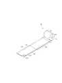
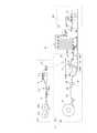
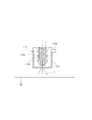
本発明にかかる一次原反ロールJR(ジャンボロールとも称される)は、図1に示す抄紙設備例X1により、以下のようにして製造することができる。[First embodiment: non-embossed form]
[Paper making process: Manufacturing method and manufacturing equipment for primary roll]
The primary raw roll JR (also referred to as jumbo roll) according to the present invention can be manufactured as follows using the papermaking equipment example X1 shown in FIG.
まず、ヘッドボックス31からパルプスラリーに適宜の薬品を添加して予め調整した紙料をワイヤーパート32のワイヤ32w上に供給して湿紙Wを形成し(フォーミング工程)、次にこの湿紙Wをプレスパート33のフェルト33Fに移送したにのち対をなす脱水ロール34,35によって挟持して脱水する(脱水工程)。 First, a paper stock prepared by adding an appropriate chemical to the pulp slurry from the
次いで、脱水された湿紙Wをヤンキードライヤー36の表面に付着させて乾燥させた後にドクターブレード37によって掻き剥がしてクレープを有する乾燥原紙S1(後述の一次連続シート)とする(乾燥工程)。 Next, after the dehydrated wet paper W is adhered to the surface of the
そして、この乾燥原紙S1をワインディングドラム39を有する巻き取り手段38によって、前記乾燥原紙S1の裏面が一次原反ロールJRの軸側に対向するようにして(巻き取り内面となるようにして)巻き取り、一次原反ロールJRとする(一次原反巻き取り工程)。 Then, the dried base paper S1 is wound by a winding
この一次原反ロールJRは、抄紙設備X1の性能によっても相違するが、概ね直径が1000〜5000mm、長さ(幅)が1500〜9200mm、巻き長さが5000〜80000mである。 The primary web roll JR differs depending on the performance of the papermaking equipment X1, but generally has a diameter of 1000 to 5000 mm, a length (width) of 1500 to 9200 mm, and a winding length of 5000 to 80000 m.
なお、一次原反巻き取り工程の前段にドクターブレード37により掻き剥がした乾燥原紙S1に対してカレンダー工程(図示せず)を設け表裏面の平滑化処理をしてもよい。 In addition, a calendar process (not shown) may be provided on the dry base paper S1 that has been scraped off by the
ここで、乾燥原紙S1の裏面とは、ヤンキードライヤー36のシリンダと接していた面の反対側の面のことを意味する。なお、カレンダー工程の有無にもよるが一般には鏡面のヤンキードライヤーに接していた表面のほうが滑らかで表面性に優れる。 Here, the back surface of the dry base paper S1 means a surface opposite to the surface that is in contact with the cylinder of the
ここで、一次原反ロールJRを構成する一次連続シートS1は、後にトイレットペーパー1に加工されるものであり、最終製品を構成するトイレットペーパーとほぼ同等の坪量となる。従って、これを考慮して一次連続シートS1は具体的にはJIS P 8124による坪量が、10〜25g/m2、好ましくは12〜20g/m2、より好ましくは13〜18g/m2とする。坪量が10g/m2未満であると、トイレットペーパーの柔らかさの点においては好ましいが、使用時の適正な強度の確保することが難しくなるとともに、後段のワインダーにおける再巻き取り(ログ製造)が困難となる。他方、坪量が25g/m2を超えると、トイレットペーパーが硬くなりすぎて、肌触りが悪化する。Here, the primary continuous sheet S1 constituting the primary raw roll JR is processed into the
また、紙厚(尾崎製作所製ダイヤルシックネスゲージにより測定)は80〜250μm、好ましくは100〜200μm、より好ましくは130〜180μmとするのが望ましい。 The paper thickness (measured with a dial thickness gauge manufactured by Ozaki Seisakusho) is 80 to 250 μm, preferably 100 to 200 μm, more preferably 130 to 180 μm.
また、一次連続シートS1は、クレープ率が10〜30%、好ましくは15〜28%、より好ましくは20〜25%である。クレープ率が10%未満であると、後段の加工時に断紙しやすいとともに伸びの少ないコシのないトイレットペーパーとなる。他方、クレープ率が30%超過であると、加工時のシートの張力コントロールが難しく断紙しやすくなり、また、製造後にはシワが発生して見栄えの悪いトイレットペーパーとなりやすくなる。 The primary continuous sheet S1 has a crepe rate of 10 to 30%, preferably 15 to 28%, more preferably 20 to 25%. When the crepe rate is less than 10%, it becomes easy to break the paper during subsequent processing, and the toilet paper does not stretch and has little elasticity. On the other hand, if the crepe rate is more than 30%, it is difficult to control the tension of the sheet during processing, and it is easy to break the paper.
ここで、クレープ率とは、下式で表わされるものとする。
クレープ率:{(製紙時のドライヤーの周速)−(巻き取り手段におけるリール装置のリール周速)}/(製紙時のドライヤーの周速)×100。Here, the crepe rate is expressed by the following equation.
Crepe rate: {(peripheral speed of the dryer during papermaking) − (reel peripheral speed of the reel device in the winding means)} / (peripheral speed of the dryer during papermaking) × 100.
また、一次連続シートS1は、JIS P 8113に規定される乾燥引張強度(以下、乾燥紙力ともいう)の縦方向が、2プライで300〜900cN/25mm、好ましくは350〜800cN/25mm、特に好ましくは400〜700cN/25mmとし、他方、横方向が、2プライで100〜400cN/25mm、好ましくは130〜350cN/25mm、特に好ましくは150〜300cN/25mmとするのが望ましい。原紙の乾燥引張強度が低すぎると、製造時及び使用時の断紙や伸び等のトラブルが発生し易くなり、高過ぎると使用時にごわごわした肌触りとなる。 Further, the primary continuous sheet S1 has a dry tensile strength (hereinafter also referred to as dry paper strength) defined in JIS P 8113 having a longitudinal direction of 2 to 300 to 900 cN / 25 mm, preferably 350 to 800 cN / 25 mm. Preferably, it is 400 to 700 cN / 25 mm. On the other hand, the lateral direction is 100 to 400 cN / 25 mm with 2 plies, preferably 130 to 350 cN / 25 mm, particularly preferably 150 to 300 cN / 25 mm. If the dry tensile strength of the base paper is too low, troubles such as paper breakage and elongation at the time of production and use are likely to occur, and if it is too high, the touch becomes stiff when used.
これらの紙力は公知の方法により調整でき、例えば、乾燥紙力増強剤を紙料或いは湿紙に内添する、紙料のフリーネスを低下(例えば30〜40ml程度低下)させる、原料パルプのNBKP配合率を増加(例えば50%以上に)する等の既知の手法を適宜組み合わせることができる。 These paper strengths can be adjusted by a known method. For example, NBKP of raw material pulp that reduces the freeness (for example, about 30 to 40 ml) of paper stock by adding a dry paper strength enhancer to the stock or wet paper. Known techniques such as increasing the blending ratio (for example, 50% or more) can be appropriately combined.
なお、乾燥紙力増強剤としては、澱粉、ポリアクリルアミド、CMC(カルボキシメチルセルロース)若しくはその塩であるカルボキシメチルセルロースナトリウム、カルボキシメチルセルロースカルシウム、カルボキシメチルセルロース亜鉛等を用いることができる。湿潤紙力剤としては、ポリアミドポリアミンエピクロルヒドリン樹脂、尿素樹脂、酸コロイド・メラミン樹脂、熱架橋性塗工PAM等を用いることができる。 As the dry paper strength enhancer, starch, polyacrylamide, CMC (carboxymethyl cellulose) or a salt thereof such as sodium carboxymethyl cellulose, carboxymethyl cellulose calcium, carboxymethyl cellulose zinc and the like can be used. As the wet paper strength agent, polyamide polyamine epichlorohydrin resin, urea resin, acid colloid / melamine resin, thermally crosslinkable coating PAM, and the like can be used.
乾燥紙力増強剤を内添する場合、その添加量はパルプスラリーに対する重量比で0.5〜1.0kg/t程度とすることができる。 When the dry paper strength enhancer is internally added, the addition amount can be set to about 0.5 to 1.0 kg / t by weight ratio to the pulp slurry.
湿潤紙力増強剤は、トイレットペーパーが水解性を要することから、添加しないか添加しても少量とするのが望ましい。但し、添加した場合には、後段のワインダーにおけるログ製造時において有利に作用することから、この点を考慮して、少量、具体的にはパルプスラリーに対する重量比で5kg/t以下とすることができる。 Since the wet paper strength enhancer requires water disintegration, it is desirable that the wet paper strength enhancer is not added or is added in a small amount even if it is added. However, when added, it acts advantageously during log production in the latter winder. Therefore, considering this point, a small amount, specifically, 5 kg / t or less in weight ratio to the pulp slurry may be used. it can.
ここで、一次原反ロール(一次原反シート)の原料となる紙料について説明すると、紙料は繊維原料としてパルプを主原料とするスラリー(パルプスラリー)に適宜の薬品を添加したものである。 Here, the paper material used as the raw material of the primary raw material roll (primary raw material sheet) will be described. The paper material is obtained by adding an appropriate chemical to a slurry (pulp slurry) containing pulp as a main raw material as a fiber raw material. .
本発明においては、原料パルプは特に限定されず、トイレットペーパーに用いられる適宜の原料パルプを選択して使用することができる。 In the present invention, the raw material pulp is not particularly limited, and an appropriate raw material pulp used for toilet paper can be selected and used.
好ましくは、原料パルプは、NBKPとLBKPとを配合したものが好ましい。また、古紙パルプが配合されていてもよいが、本発明にかかるローション薬液との相性がよく、ワインダーにおけるログ製造が好適に行えるともに、得られるティシュペーパーの風合いの点でも望ましいことから、バージンパルプのNBKPとLBKPのみから構成されているのがよい。その場合の配合割合(JIS P 8120)としては、NBKP:LBKP=20:80〜80:20がよく、特に、NBKP:LBKP=30:70〜60:40が望ましい。 Preferably, the raw material pulp is a blend of NBKP and LBKP. In addition, waste paper pulp may be blended, but it is compatible with the lotion chemical solution according to the present invention, log production in a winder can be suitably performed, and the texture of the resulting tissue paper is desirable, so virgin pulp It is preferable to be composed only of NBKP and LBKP. In this case, the blending ratio (JIS P 8120) is preferably NBKP: LBKP = 20: 80 to 80:20, and particularly preferably NBKP: LBKP = 30: 70 to 60:40.
紙料に添加する薬品例としては、上記乾燥紙力増強剤、湿潤紙力増強剤のほか剥離剤、接着剤、苛性ソーダ等のpH調整剤、粘剤、消泡剤、防腐剤、スライムコントロール剤、染料、などが挙げられる、なお、これらの薬品は、適宜の工程で湿紙に塗工してもよい。 Examples of chemicals added to the paper stock include the above-mentioned dry paper strength enhancer, wet paper strength enhancer, release agent, adhesive, pH adjuster such as caustic soda, sticky agent, antifoaming agent, preservative, slime control agent In addition, these chemicals may be applied to the wet paper in an appropriate process.
〔プライマシンにおける工程:二次原反ロールの製造方法及び製造設備〕
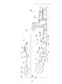
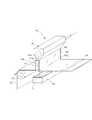
本発明においては、抄紙設備X1で製造された一次原反ロールJRを、特徴的に、図2に例示するプライマシンX2において、薬液が付与された二次原反ロールRを製造する。[Process in ply machine: manufacturing method and manufacturing equipment for secondary roll]
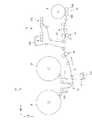
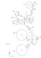
In the present invention, the primary raw roll JR manufactured by the papermaking facility X1 is characteristically manufactured by the ply machine X2 illustrated in FIG.
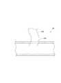
本形態にかかるプライマシンX2は、一次原反ロールJRを2つ以上セット可能であり、各一次原反ロールJR,JRから繰り出した一次連続シート(図示例ではS11、S12)は、その連続方向に沿って積層して積層連続シートS2とする重ね合わせ部(積層手段)51に供給されるように構成されている。ここで重ね合わせ部51は一対のニップロールで構成され、各一次連続シートS11,S12を積層するとともにニップして各一次連続シートを積層一体化ならしめる。 The ply machine X2 according to this embodiment can set two or more primary web rolls JR, and primary continuous sheets (S11, S12 in the illustrated example) fed out from the primary web rolls JR, JR are in the continuous direction. The sheet is supplied to an overlapping portion (laminating means) 51 that is laminated along the sheet to form a laminated continuous sheet S2. Here, the overlapping
なお、図示例では、各一次原反ロールJR,JRから繰り出される一次連続シートS11,S12の表面が、それぞれ積層連続シートS2の表面(ここで積層連続シートの「表面」とは積層外面である積層連続シートS2の表裏面のことである)となるようして重ね合わせ部51に供給されるようになっている。一次連続シートS11,S12の裏面がそれぞれ積層連続シートS2の表面となるよう構成してもよいし、一次連続シートS11,S12のどちらか一方の裏面が積層連続シートS2の表面となり、他方の表面が積層連続シートS2の表面となるようしてもよいが、一次原反シートS11,S12の表面は、乾燥時にヤンキードライヤーの表面に接していることから裏面と比較して毛羽立ちが少なく滑らかで肌触りが良いので、一次連続シート(乾燥原紙S1)の表面が積層連続シートS2の表裏面を構成するようにするのが望ましい。 In the illustrated example, the surfaces of the primary continuous sheets S11 and S12 fed out from the primary raw rolls JR and JR are respectively the surfaces of the laminated continuous sheets S2 (here, the “surface” of the laminated continuous sheets is the laminated outer surface). (The front and back surfaces of the laminated continuous sheet S2). You may comprise so that the back surface of primary continuous sheet S11, S12 may become the surface of lamination | stacking continuous sheet S2, respectively, either one back surface of primary continuous sheet S11, S12 may become the surface of lamination | stacking continuous sheet S2, and the other surface May be the surface of the laminated continuous sheet S2, but the surface of the primary raw sheet S11, S12 is in contact with the surface of the Yankee dryer during drying, so there is less fuzz compared to the back surface, and it is smooth and soft to the touch Therefore, it is desirable that the surface of the primary continuous sheet (dry base paper S1) forms the front and back surfaces of the laminated continuous sheet S2.
また、図示例では一次原反ロールJRを2つセットしていわゆる2プライの積層連続シートを巻き取る例であるが、3セット、4セットとして3プライ、4プライの積層連続シートを巻き取るようにすることも可能である。 In the illustrated example, two primary web rolls JR are set and a so-called two-ply laminated continuous sheet is wound, but three sets, four sets of three-ply and four-ply laminated continuous sheets are wound. It is also possible to make it.
本第1の実施の形態では、プライマシンX2の重ね合わせ部51の後段に薬液付与手段53を有し、積層連続シートS2に対して連続的に薬液を付与する薬液付与工程を行なうようになっている。なお、重ね合わせ部51と薬液付与手段53との前後関係を入れ替えて、各一次連続シートS11,S12に薬液を付与した後に、薬液付与した一次連続シートを積層するようにしてもよい。 In the first embodiment, the
プライマシンX2にて積層連続シートS2に対して薬液を塗工するには、フレキソ印刷、スプレー塗工、インクジェット印刷等の薬液付与手段53を採用することができる。但し、プライマシンX2の高速性に対応でき、しかも刷版の柔軟性、高速対応性、薬液の飛散防止、塗工量の調整が容易である等の要件からフレキソ印刷が適する。紙面に刷版ロール等を接触させないことから紙厚の低下を招かないという点では、刷版ロール等を用いず直接的に薬液を紙面に塗工する非接触形の塗工形態であるスプレー塗工、インクジェット印刷、カーテン塗工が望ましい。但し、これらの非接触式の塗工は薬液の均一塗布、塗工量の調整がフレキソ印刷等のロール転写式の付与手段と比較して高速性の点では劣り、また、後述のエンボス付与を行なう各形態では係る欠点が顕著となる。従って、本発明においては、ロール転写方式のほうが望ましく、総合的にはフレキソ印刷が最も望ましい。 In order to apply a chemical solution to the laminated continuous sheet S2 by the ply machine X2, a chemical solution applying means 53 such as flexographic printing, spray coating, and ink jet printing can be employed. However, flexographic printing is suitable because it can cope with the high speed of the ply machine X2, and the printing plate has flexibility, high speed compatibility, prevention of chemical dispersion, and easy adjustment of the coating amount. Spray coating, which is a non-contact type coating method in which a chemical solution is directly applied to the paper surface without using the printing plate roll or the like, in that the plate thickness is not reduced because the printing plate roll is not brought into contact with the paper surface. Work, ink jet printing and curtain coating are desirable. However, these non-contact coating methods are inferior in terms of high speed compared with roll transfer type application means such as flexographic printing, etc., with uniform application of chemicals and adjustment of the coating amount, and embossing described later is also applied. In each of the forms to be performed, such a drawback becomes remarkable. Therefore, in the present invention, the roll transfer method is more preferable, and flexographic printing is most preferable overall.
薬液付与手段53は、単数或いは複数設置することができ。図示例では、二機のドクターチャンバー式フレキソ印刷機53A,53Bを設置して積層連続シートS2の両外面に薬液を付与する態様を示している。薬液付与手段53を、複数設置する場合、水平方向、上下方向、或いは斜め方向に並設しても良く、水平方向を含めたこれらの設置方向を組み合わせて配置しても良い。水平方向に並設すると抱き角度を小さくすることができるため、加工速度を高速とすることができ、上下方向に並設すると水平方向における設置スペースを小さくすることができる。 One or a plurality of chemical solution applying means 53 can be installed. In the illustrated example, two doctor chamber-type
薬液の塗工量は、両外面(トイレットペーパーの外面となる各面)の合計の薬液塗工量は、0.3〜5.0g/m2、好ましくは1.0〜3.9g/m2、より好ましくは2.0〜3.0g/m2とする。3.9g/m2超過であると、紙力低下や伸びなどにより断紙したり、品質的にべたつき感が過ぎる場合も出てくるとともに、後述のワインダーでの再巻き取り(ログ製造)が困難となる。0.3g/m2未満であると滑らかさやしっとり感など未塗工品との品質差を感じられなくなってしまう。より好ましく、2.0〜3.0g/m2とすると厚み感、しっとり感といった官能評価において極めて優れたものとなる。The coating amount of the chemical solution is 0.3 to 5.0 g / m2 , preferably 1.0 to 3.9 g / m, and the total chemical coating amount of both outer surfaces (each surface serving as the outer surface of the toilet paper).2 and more preferably 2.0 to 3.0 g / m2 . If it exceeds 3.9 g / m2 , the paper may be cut off due to a decrease in paper strength or elongation, or the texture may be too sticky, and rewinding (log production) with a winder described later may occur. It becomes difficult. If it is less than 0.3 g / m2 , the difference in quality from uncoated products such as smoothness and moistness cannot be felt. More preferably, when it is set to 2.0 to 3.0 g / m2 , the sensory evaluation such as thickness feeling and moist feeling becomes extremely excellent.
なお、本発明においては、トイレットペーパーの両外面となる部分への薬液付与の薬液付与量が異なるようにしてもよい。また、トイレットペーパーの外面となる各面の片面ののみに薬液を付与するようにしてもよい。 In addition, in this invention, you may make it make the chemical | medical solution provision amount of the chemical | medical solution provision to the part used as the both outer surfaces of toilet paper differ. Moreover, you may make it provide a chemical | medical solution only to the single side | surface of each surface used as the outer surface of toilet paper.
薬液付与工程で付与する薬液については、粘度は40℃で1〜700mPa・sが望ましい。より好ましくは50〜400mPa・s(40℃)である。1mPa・sより小さいと特に、薬液が飛散しやすくなり、逆に700mPa・sより大きいと安定した付与量とするコントロールがしにくくなる。 About the chemical | medical solution provided at a chemical | medical solution provision process, 1-700 mPa * s is desirable at 40 degreeC. More preferably, it is 50-400 mPa * s (40 degreeC). If it is less than 1 mPa · s, the chemical solution is likely to scatter, and conversely if it is greater than 700 mPa · s, it becomes difficult to control the amount to be applied stably.
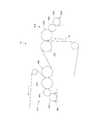
本発明に用いる薬液は、水系のローション薬液であり、その成分は、水及びポリオールを含むものである。特にポリオールを70〜90%、水分を1〜15%を含むのが望ましく、さらに機能性薬品を0.01〜22%含むものであるのがより望ましい。 The chemical solution used in the present invention is an aqueous lotion chemical solution, and its components include water and a polyol. In particular, it is desirable to contain 70 to 90% of polyol and 1 to 15% of water, and more desirably 0.01 to 22% of functional chemicals.
前記ポリオールとしては、グリセリン、ジグリセリン、プロピレングリコール、1,3−ブチレングリコール、ポリエチレングリコール、およびその誘導体等の多価アルコール、ソルビトール、グルコース、キシリトール、マルトース、マルチトール、マンニトール、トレハロース等の糖類が挙げられる。 Examples of the polyol include polyhydric alcohols such as glycerin, diglycerin, propylene glycol, 1,3-butylene glycol, polyethylene glycol, and derivatives thereof, and sugars such as sorbitol, glucose, xylitol, maltose, maltitol, mannitol, and trehalose. Can be mentioned.
上記成分のうち、グリセリン、プロピレングリコール等の多価アルコールを主成分とすることが、滑らかさ、保湿性等の官能高価、及び薬液の粘度、付与量を安定させる上で好ましい。 Among the above components, it is preferable to use a polyhydric alcohol such as glycerin or propylene glycol as a main component in order to stabilize the functional cost such as smoothness and moisturizing property, and the viscosity and applied amount of the chemical solution.
前記機能性薬剤としては、柔軟剤、界面活性剤、無機および有機の微粒子粉体、油性成分などがある。柔軟剤、界面活性剤はティシューに柔軟性を与えたり表面を滑らかにする効果があり、アニオン性界面活性剤、カチオン性界面活性剤及び両性イオン界面活性剤を適用する。無機および有機の微粒子粉体は表面を滑らかな肌触りとする。油性成分は滑性を高める働きがあり、流動パラフィン、セタノール、ステアリルアルコール、オレイルアルコール等の高級アルコールを用いることができる。 Examples of the functional agent include softeners, surfactants, inorganic and organic fine particle powders, and oily components. Softeners and surfactants have the effect of imparting flexibility to the tissue and smoothing the surface, and anionic surfactants, cationic surfactants and zwitterionic surfactants are applied. Inorganic and organic fine particle powders have a smooth surface. The oil component has a function of improving lubricity, and higher alcohols such as liquid paraffin, cetanol, stearyl alcohol, and oleyl alcohol can be used.
また機能性薬剤としてポリオールの保湿性を助けたり、維持させる薬剤として親水性高分子ゲル化剤、コラーゲン、加水分解コラーゲン、加水分解ケラチン、加水分解シルク、ヒアルロン酸若しくはその塩、セラミド等の1種以上を任意の組合せ等の保湿剤を加えることができる。 In addition, as a functional agent, one of a hydrophilic polymer gelling agent, collagen, hydrolyzed collagen, hydrolyzed keratin, hydrolyzed silk, hyaluronic acid or a salt thereof, ceramide, etc. A moisturizing agent such as any combination can be added.
また機能性薬剤として各種天然エキス等のエモリエント剤、ビタミン類、配合成分を安定させる乳化剤、薬液の発泡を抑え付与を安定させるための消泡剤、防黴剤、有機酸などの消臭剤を適宜配合することができる。さらには、ビタミンC、ビタミンEの抗酸化剤を含有させてもよい。 As functional agents, emollients such as various natural extracts, vitamins, emulsifiers that stabilize compounding ingredients, antifoaming agents, antifungal agents, organic acids and other deodorizing agents that suppress the foaming of chemicals and stabilize their application. It can mix | blend suitably. Furthermore, you may contain the antioxidant of vitamin C and vitamin E.
薬液付与時の温度は30℃〜60℃、好ましくは35℃〜55℃とすることが好ましい。 The temperature at the time of chemical solution application is preferably 30 ° C to 60 ° C, preferably 35 ° C to 55 ° C.
ここで、薬液塗工タイプの製品に用いられる薬液は種々存在するが、大きく本発明にかかる水及びポリオールを含む水系薬液、主に非水溶性のワックス等を含み常温で半固形である油系薬液に大別される。水系薬液は取り扱い性に優れ安価であり水解性の低下がほとんどないという特徴がある。 Here, there are various types of chemicals used for chemical coating type products, but water-based chemicals containing water and polyols according to the present invention, oil systems mainly containing water-insoluble wax, etc. and semi-solid at room temperature Broadly divided into chemicals. Aqueous chemicals are characterized by excellent handling and low cost and almost no degradation in water disintegration.
また、水系薬液はシートに塗工した場合にシートを構成するパルプ繊維との親和性に優れ、シートの厚み方向(Z方向とも称される)に含浸し、シート全体及びその表面性を改質するように作用する。これに対して油系薬液は主にその表面をコーティングするように作用し、表面の滑らかさを向上させるように作用し、水解性を悪化させる。他方で、水系薬液は、シートに含浸することから塗工後にシートに塗工されたクレープを伸ばす作用が大きく紙力低下を伴うが、油系薬液ではそのような作用が小さい。 In addition, aqueous chemicals have excellent affinity with the pulp fibers that make up the sheet when applied to the sheet, impregnate in the thickness direction of the sheet (also called the Z direction), and modify the entire sheet and its surface properties. Acts like On the other hand, the oil-based chemical solution mainly acts to coat the surface thereof, acts to improve the smoothness of the surface, and deteriorates water decomposability. On the other hand, since the aqueous chemical solution impregnates the sheet, the action of stretching the crepe applied to the sheet after coating is large and accompanied by a decrease in paper strength. However, the action of the oil-based chemical liquid is small.
本発明はかかる水系の薬液を十分な量、用いつつも安定的かつ高速に生産することができ、保湿性(しっとり感)、柔軟性(柔らかさ感)、表面の滑らかさ性(滑らかさ感)の向上と生産性の向上が図られるのである、 The present invention can produce a sufficient amount of such a water-based chemical solution stably and at high speed, and is moisturizing (moist), soft (soft), and smooth on the surface (smooth). ) And productivity.
上記薬液付与工程53にて薬液が付与された積層連続シートS3は、巻き取り手段56に案内されて巻き取られ二次原反ロールRとされる。巻き取り手段56は、回転可能な管軸に巻かれた積層連続シートS3の外面に接して回転する一対のワインディングドラム56A,56Bを有し、これら2つのワインディングドラム56A,56A及び上記管軸が適宜回転することで、薬液が付与された積層連続シートS3を案内しつつ巻き取る。 The laminated continuous sheet S3 to which the chemical liquid is applied in the chemical
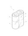
ここで、二次原反ロールRは、トイレットロールの巻き径(直径)と比較して極めて大径のロールであり、トイレットロールの巻き径と同じ径の所謂ログとは異なるものである。 Here, the secondary raw fabric roll R is a roll having a very large diameter as compared with the roll diameter (diameter) of the toilet roll, and is different from a so-called log having the same diameter as the roll diameter of the toilet roll.
本発明は一次原反ロールJRからログを直接的に製造せずプライマシンX2により薬液が付与された二次原反ロールRを製造する工程を有する点で特徴的である。 The present invention is characterized in that it has a step of producing a secondary raw roll R to which a chemical solution is applied by the ply machine X2 without directly producing a log from the primary raw roll JR.
ここで、本発明におけるプライマシンX2においてされる好ましい種々の加工及び手段の詳細について以下、さらに説明する。 Here, details of various preferable processes and means performed in the ply machine X2 in the present invention will be further described below.
プライマシンX2においてトイレットロール用の薬液が付与された二次原反ロールRを製造するにあたっては、加工速度を300〜900m/分、好ましくは500〜900m/分、より好ましくは700〜800m/分とするのが望ましい。300m/分未満だと十分な生産性とは言えない。他方、900m/分超過であると安定的に生産するのが困難となる。特に500m/分、より好ましく700m/分であると後段のワインダーへの供給、十分なストック管理、さらに複数のワインダーの運用が可能になるなど生産性を高めるうえで好ましい。800m/分以下とすると安定性がより優れる。 In producing the secondary raw roll R to which the chemical solution for toilet roll is applied in the ply machine X2, the processing speed is 300 to 900 m / min, preferably 500 to 900 m / min, more preferably 700 to 800 m / min. Is desirable. If it is less than 300 m / min, it cannot be said that the productivity is sufficient. On the other hand, if it exceeds 900 m / min, stable production becomes difficult. In particular, 500 m / min, more preferably 700 m / min, is preferable from the viewpoint of increasing productivity, for example, supply to a winder in the subsequent stage, sufficient stock management, and the operation of a plurality of winders. When it is 800 m / min or less, the stability is more excellent.
なお、少なくとも速度は300m/分以上、通常は500m/分以上、好ましくは700m/分以上の加工速度は、従来のトイレットロールの生産性からすると極めて高速な加工速度である。 A processing speed of at least 300 m / min, usually 500 m / min or more, preferably 700 m / min or more is a very high processing speed in terms of the productivity of conventional toilet rolls.
他方、プライマシンX2においては、巻き取り部56の前段にスリット手段55を設けて、薬液が付与された積層連続シートS3を連続方向にスリットして適宜の幅とした後に、それらスリットされた積層連続シートS3を巻取ることで後段のワインダーに適した適宜の幅の二次原反ロールRとすることができる。 On the other hand, in the ply machine X2, the slit means 55 is provided in the preceding stage of the winding
なお、ここでのスリットは、トイレットロールの幅ではなく後段のワインダーに適した幅であり、概ね積層連続シートS3を半裁、或いは1/3裁程度にスリットすることを意味する。 The slit here is not a width of the toilet roll but a width suitable for a winder at a later stage, and generally means that the laminated continuous sheet S3 is slit in half or about 1/3.
スリット加工を行なうスリット手段55は、積層連続シートS3の幅方向に間隔を開けて並設された複数のロールカッター及び受け部からなるスリット手段とすることができる。 The slit means 55 that performs the slit processing can be a slit means that includes a plurality of roll cutters and receiving portions arranged in parallel at intervals in the width direction of the laminated continuous sheet S3.
他方、プライマシンX2においては、重ね合わせ部51から巻き取り部56までの間にカレンダー部52を一つ以上設けて薬液付与に前後して積層連続シートS2、S3に対してカレンダー加工をすることができる。図示例では、重ね合わせ部51の後段であって薬液付与手段53の前段に設けており、かかる位置に設けるのが望ましい。 On the other hand, in the ply machine X2, one or
カレンダー部52におけるカレンダーの種別は、特に限定されないが、表面の平滑性向上と紙厚の調整の理由からソフトカレンダー又はチルドカレンダーとすることが好ましい。ソフトカレンダーとは、ウレタンゴム等の弾性材を被覆したロールを用いたカレンダーであり、チルドカレンダーとは金属ロールからなるカレンダーのことである。 The type of calendar in the
カレンダー部の数は、適宜変更することができる。複数設置すれば加工速度が速くとも十分に平滑化できるという利点を有する一方、一つであるとスペースが狭くとも設置可能であるという利点を有する。 The number of calendar parts can be changed as appropriate. If there is a plurality of installations, it has the advantage that it can be sufficiently smoothed even if the processing speed is high. On the other hand, one installation has the advantage that it can be installed even if the space is small.
二つ以上のカレンダー部を設置する場合、水平方向、上下方向、或いは斜め方向に並設することができ、また、これらの設置方向を組み合わせて配置することができる。水平方向に並設すると、抱き角度を小さくなるため加工速度が高速とすることができ、上下方向に並設すると設置スペースを小さくすることができる。なお、ここで言う抱き角度とはロールの軸中心から見てシートが接している間(軸と直行する断面の円弧の一部)の角度を意味する(以下同じ)。 When two or more calendar parts are installed, they can be arranged side by side in the horizontal direction, the up-down direction, or the oblique direction, and these installation directions can be combined. When arranged side by side in the horizontal direction, the holding angle becomes smaller, so the processing speed can be increased, and when arranged side by side in the vertical direction, the installation space can be reduced. The holding angle referred to here means an angle during which the sheet is in contact with the roll as viewed from the center of the roll axis (a part of an arc of a cross section perpendicular to the axis) (hereinafter the same).
カレンダー加工におけるカレンダー種別、ニップ線圧、ニップ数なども制御要因として抄紙を行うようにし、これらの制御要因は、求めるトイレットペーパーの品質すなわち紙厚や表面性によって適宜変更することが好ましい。 Paper making is also performed as control factors such as calendar type, nip line pressure, and number of nips in calendar processing, and these control factors are preferably changed as appropriate depending on the quality of toilet paper desired, that is, paper thickness and surface properties.
〔ワインダーにおける工程:ログ製造工程〕
上記のとおりプライマシンX2にて薬液が付与された積層連続シートS3を巻取った二次原反ロールを製造した後には、これをワインダーX3に移送してログ10Rを製造する。図3には、ログ製造に用いる長尺の紙管11Lを製造する工程(A)、ログ製造工程(B)、裁断工程(C)を示す。(B)に示される部分がワインダーにおけるログ製造工程である。ここでは、長尺紙管11Lの製造工程(A)も合わせて説明する。[Process in winder: log manufacturing process]
After manufacturing the secondary raw roll which wound up lamination | stacking continuous sheet S3 to which the chemical | medical solution was provided with the ply machine X2 as mentioned above, this is transferred to the winder X3 and the
長尺の紙管11Lを製造する工程(図3中(A))は、図4にも示すように、二枚の帯状の紙管用原紙(板紙)12,12を原反ロール12A,12Aからそれぞれ繰り出しつつ、所定位置に糊付けロール13により糊を付与し、当該糊付けされた部分を重ねつつコアワインダー14によりシャフト15に螺旋状に巻付け、ワインダー或いは二次原反ロールRの幅に合わせた所定長さにスリッター16にて切り揃えることで、円筒の長尺の紙管11Lを形成する。なお、各紙管用原紙12,12は、各々違う原反を使用してもよく、例えば、一方に印刷を施したり、各々の米坪を変えたりしてもよい。本発明においても、必ずしも紙管原紙12,12は、同様のものである必要はない。なお、紙管の直径は35〜50mmとするのが望ましい。 As shown in FIG. 4, the step of manufacturing the
次いで、この長尺紙管11Lの製造と平行して又はその後において、ワインダーX3にてログ10Rを製造する。なお、ログ10Rとは、業界においての一般用語であり、トイレットロールの径と同径でありかつ幅がトイレットロールの複数個分ある中間製品である。 Next, in parallel with or after the manufacture of the
本第1の実施形態にかかるワインダーX3は、原反ロール支持部、コンタクトエンボス手段54、パーフォレーションロール71を有するミシン目線付与手段70、再巻き取り手段75をこの順で備える。 The winder X3 according to the first embodiment includes a raw roll support portion, a contact embossing means 54, a perforation line giving means 70 having a
本第1の実施形態におけるログ10Rの製造は、ワインダーX3の原反ロール支持部にセットした薬液が付与された積層連続シートS3が巻き取られた二次原反ロールRから連続的に積層状態の二次連続シートS4を巻きだし、コンタクトエンボス手段54でコンタクトエンボスを付与した後、ミシン目線付与手段70によって二次連続シートS4に対して流れ方向に所定間隔で二次連続シートS4の幅方向に沿ってミシン目線を形成し、その後に再巻き取り手段75でトイレットロールの巻き径となるように巻き直してログ10Rを製造する。 The production of the
前記コンタクトエンボス手段(コンタクトエンボス工程)54は、図5に示すように、金属ロール又は弾性ロールである受けロール154Bと表面に細かい凸部154Cを有する金属製で硬質のコロ154Aとが所定の圧力を有して相互に外周面同士を当接しつつ、それぞれ回転可能に設置されている。そして、二次連続シートS4におけるトイレットロールの幅L1の幅方向中央に該当する部分に対して、左右各2つずつ存在する凸部154Cと、受けロール154Bとの間で二次連続シートS4を挟みつつ搬送することで、二次連続シートS4に対して、二次連続シートS4の連続方向に沿って層間剥離を防止するライン状のコンタクトエンボスCEを施すようになっている。 As shown in FIG. 5, the contact embossing means (contact embossing step) 54 includes a receiving
尚、このコンタクトエンボスCEを施すコロ154Aと対向した側の面を外周側として後段の再巻き取り手段75において二次連続シートS4を巻き取りログ10Rとするのが望ましい。 The secondary continuous sheet S4 is preferably used as the take-up
このようにコンタクトエンボスCEを付与することによって、複数の一次連続シート(S11、S12)を積層して成る二次連続シートS4の層間剥離が防止される。 By providing the contact embossing CE in this way, delamination of the secondary continuous sheet S4 formed by laminating a plurality of primary continuous sheets (S11, S12) is prevented.
また、このコンタクトエンボス工程54において、本実施形態ではコロ154Aとして表面に細かい凸部154Cを有した金属製で硬質のコロ154Aを用いたが、二次連続シートS4に対して層間剥離を防止するライン状の接合部分が形成できればよく、例えばコロ154Aの替りに、表面に細かい針状の部材を有したローラをコロとすることもできる。 Moreover, in this
さらに、接合する為の手段としては上記例に限定されず、凸部の先端形状が、点状、正方形、長方形、円形、楕円形等の形状のものをコロとして用いても良く、凸部の先端形状が、細長い線状、細く斜めに伸びる線状等のものをコロとして用いても良い。 Furthermore, the means for joining is not limited to the above example, and the tip shape of the convex portion may be a point, square, rectangular, circular, elliptical shape, etc. A tip having a slender linear shape or a thin and slanting linear shape may be used as the roller.
他方、凸部の配列としては等間隔が考えられるが、千鳥状としたり、等間隔としなくとも良く、また、凸部を1列に配置してコンタクトエンボスを連続して付与する他に、凸部を2列以上の複数列配置することも考えられる。そして、コンタクトエンボスを緊密に複数列付与するように凸部が配置された群を複数並べて、複数のコンタクトエンボス群を付与するようにしても良い。尚、接合工程としては、上記のように機械的に圧力を加えて接合する他に、超音波等の他の手段により接合しても良い。 On the other hand, the arrangement of the protrusions may be equally spaced, but may not be staggered or evenly spaced. In addition to arranging the protrusions in a row and providing contact embossing continuously, It is also conceivable to arrange the parts in two or more rows. Then, a plurality of groups in which convex portions are arranged so as to provide a plurality of rows of contact embossing closely may be arranged to provide a plurality of contact embossing groups. In addition, as a joining process, you may join by other means, such as an ultrasonic wave, besides joining by applying a pressure mechanically as mentioned above.
なお、図示例においては、コンタクトエンボス手段54は、ワインダーX3に設置したが、本形態では上記プライマシンX2における重ね合わせ部51の後段に設置して予めコンタクトエンボスが付与された二次原反ロールを製造し、これを用いてワインダーX3においてコンタクトエンボスを付与しない態様としてもよい。なお、このようにするプライマシンX2でコンタクトエンボスを付与する場合、プライマシンX2においてスリット工程を行なう場合にはその前段、より好ましくは、さらに薬液付与手段53の後段であるのが望ましい。 In the illustrated example, the contact embossing means 54 is installed in the winder X3. However, in this embodiment, the secondary embossing roll provided with the contact embossing in advance is installed after the overlapping
他方、ワインダーX3におけるミシン目線付与手段70は、周面に軸心方向に沿って多数の刃が配設された刃列を有する所謂パーフォレーションロール71とこのロールと対をなす受けロール72とで構成されており、パーフォレーションロール71と受けロール72との間に二次連続シートS4を通す際に、パーフォレーションロール71の鋸刃が二次連続シートS4に接触して二次連続シートS4に対してミシン目線を付与する。パーフォレーションロール71の鋸刃は、周面に間隔を開けて複数列形成されており、パーフォレーションロール71の回転により、二次連続シートS4の流れ方向に所定間隔でミシン目線が形成される。 On the other hand, the perforation line giving means 70 in the winder X3 is constituted by a so-called
ここで、本発明にかかるトイレットロールでは、好適にはミシン目線における二次連続シートの長手方向の引張り強さが10〜200cN(好ましくは40〜60cN)であるのがよい。この範囲であると製造時にミシン目線で分断する事故のおそれが格段に小さくなるとともに、トイレットロールとして使用する際にミシン目線で確実に裁断することが好適に行えるようになる。ここで「ミシン目線における二次連続シートの長手方向の引張り強さ」とは、JIS P 8113に規定される引張り特性試験方法に準拠して測定される乾燥時引張り強さを意味し、シート自体、つまりミシン目線のないシートの引張り強さではなく、ミシン目線のあるシートを対象とし、ミシン目線を跨いで測定した引張り強度を意味する。 Here, in the toilet roll according to the present invention, the tensile strength in the longitudinal direction of the secondary continuous sheet at the perforation line is preferably 10 to 200 cN (preferably 40 to 60 cN). Within this range, the risk of accidents that occur at the perforation line at the time of manufacture is remarkably reduced, and when used as a toilet roll, it can be suitably cut reliably at the perforation line. Here, “the tensile strength in the longitudinal direction of the secondary continuous sheet at the perforation line” means the tensile strength during drying measured in accordance with the tensile property test method defined in JIS P 8113, and the sheet itself That is, it means not the tensile strength of a sheet without a perforation line but the tensile strength measured across the perforation line for a sheet with a perforation line.
このミシン目線における長手方向の引張り強さの調節は、二次連続シートの紙力、坪量等とともにミシン目線における接続部であるタイ長さと、同分断部であるカット長さとを調節することにより、あるいはこのタイ長さとカット長さとの比であるタイカット比を調節することにより、行うことができる。 The tensile strength in the longitudinal direction at the perforation line is adjusted by adjusting the tie length that is the connecting part at the perforation line and the cut length that is the same dividing part as well as the paper strength and basis weight of the secondary continuous sheet. Alternatively, this can be achieved by adjusting the tie cut ratio, which is the ratio of the tie length to the cut length.
タイカット比の調整は、より具体的には、所望のタイカット長さ及びタイカット比の刃列を用いることで調節することができる。また、この引張り強さの調節は、パーフォレーションロールのシートへの押付け線圧(シート単位幅当たりのシートへの押付け力(kgf/cm))の調節や、ワインダー速度(巻き取り速度)の調節によっても調節することができる。 More specifically, the tie cut ratio can be adjusted by using a blade row having a desired tie cut length and tie cut ratio. The tensile strength can be adjusted by adjusting the pressing line pressure of the perforation roll to the sheet (pressing force on the sheet per sheet unit width (kgf / cm)) or by adjusting the winder speed (winding speed). Can also be adjusted.
なお、本発明におけるミシン目線の好適な構成は、カット長さを0.9〜37.5mmにするとともに、タイカット比(タイ:カット)を1:15〜1:1に設定するのが望ましい。 In addition, as for the suitable structure of the perforation line in this invention, while setting cut length to 0.9-37.5 mm, it is desirable to set a tie-cut ratio (tie: cut) to 1: 15-1: 1. .
他方、ワインダーX3は、前記長尺の紙管製造工程(図3中(A))で製造した長尺の紙管11Lが挿入されるシャフト及びシャフトを回転させる駆動装置及び糊付け装置を有しており、ログ製造10Rにあたっては、まず、長尺の紙管11L内にシャフトが挿入され、シャフトが挿入された紙管外面に適宜糊が付与される。 On the other hand, the winder X3 has a shaft into which the
その後に二次連続シートS4の先端縁が前記接着糊を介して長尺紙管11Lに接着され、その後にシャフトが回転駆動されて、長尺紙管11Lに二次連続シートS4が巻き掛けられる。 Thereafter, the leading edge of the secondary continuous sheet S4 is bonded to the
そして、長尺紙管11Lに対してトイレットロールに対応する所定長さの二次連続シートS4が巻き掛けられトイレットロールに対応する巻き径(直径)かつトイレットロールの幅の複数倍幅以上のロールが形成された後、シャフトの回転駆動を停止し、後続の二次連続シートS4との間を切断して、ログ10Rとする。 Then, a roll having a winding diameter (diameter) corresponding to the toilet roll and a multiple of the width of the toilet roll is wound around the
なお、後続の二次連続シートとの切り離しによって自由端となる部分(テールとも称される)は既知のテールシーラー機構により巻き外面に接着糊などにより接着される。 Note that a portion (also referred to as a tail) which becomes a free end by being separated from the subsequent secondary continuous sheet is bonded to the outer surface of the winding by an adhesive paste or the like by a known tail sealer mechanism.
ここで、長尺紙管11L外面に二次連続シートS4を接着させるため、或いはテールを巻き外面に接着させるための糊としては、クリル酸系樹脂、PVA(ポリビニールアルコール)、CMC(カルボキシルメチルセルロース)、デンプン、さらに単なる水などトイレットペーパーの水解性を妨げない水性の既知の糊が好適に利用できる。 Here, as a paste for adhering the secondary continuous sheet S4 to the outer surface of the
なお、ログは巻径が100〜120mm、巻長が20〜120mとなるようにすると、再巻き取り時における巻きずれがし難く望ましい。 Note that it is desirable that the log has a winding diameter of 100 to 120 mm and a winding length of 20 to 120 m, so that it is difficult for the winding to shift during rewinding.
〔ログカッターにおける裁断工程〕
ワインダーX3にてログ10Rが製造された後には、これをログアキュームレーターX4に連続的或いは簡潔的に移送する。ログアキュームレーターX4は、ログ10Rを高さ方向、横方向に移動させつつ複数本ストックしつつ後段のログカッターX5に移送する既知の装置である。[Cutting process in log cutter]
After the
ログアキュームレーターX4から順次ログカッターX5に移送されたログは、必要に応じて幅方向両端部をトリム除去するとともに、トイレットロールの幅毎に裁断されて個々のトイレットロール10とされる。ログカッターX5は、ログ10R周面に接するように複数間隔を開けて配された回転する丸刃76を有し、かかる丸刃によってログ10Rをトイレットロール10の幅に裁断する。 The log sequentially transferred from the log accumulator X4 to the log cutter X5 is trimmed at both ends in the width direction as necessary, and is cut into each toilet roll width to form individual toilet rolls 10. The log cutter X5 has a
かくして、紙管11にトイレットペーパーS5が巻かれた個々のトイレットロール10が製造される。この製造されるトイレットロールは図6に示すとおり、長尺紙管11Lが裁断された紙管11に二次連続シートS4が裁断されたトイレットペーパーS5が巻かれて成るものである。 Thus, individual toilet rolls 10 in which the toilet paper S5 is wound around the
ここで、本発明にかかるトイレットロール10の好適な例は、図6に示すとおり、幅L1が100〜115mm、直径L4が100〜120mm、巻き長さ(トイレットペーパーの全長)が18〜70m、紙管の直径が35〜50mmである。ミシン目線間隔L2は100〜300mmである。かかる構成のトイレットロール10は、ワインダーX3での薬液付与を行なって製造するとログの紙管に近い芯部分が飛び出す等の巻きずれが生ずる、薬液の浸透に伴うログの型くずれが生ずる、ミシン目線形成時に破断が生ずる等の問題点があり、製造することが極めて困難であるところ、本発明にかかる製造方法を採ることで、製造することが容易に行えるようになる。 Here, suitable examples of the
また、本発明に係るトイレットペーパーは、少なくともJIS P 4501で規定される、ほぐれやすさの試験方法における水解性の結果が80秒以下を確保できる。通常は80秒を超えると、水解性が遅く、例えば水洗トイレ等に廃棄したときに排水管に詰まるおそれがある。特に、本発明にかかるトイレットペーパーは、従来の薬液付与タイプでは困難であった、35秒以下を達成することが可能である。すなわち、本発明は十分な水解性を有するトイレットペーパーからなるトイレットロールを高効率に生産できるのである。 In addition, the toilet paper according to the present invention can secure a water disintegration result of at least 80 seconds in the test method for ease of loosening defined by at least JIS P 4501. Usually, if it exceeds 80 seconds, the water disintegration property is slow, and there is a possibility that the drain pipe is clogged when discarded in a flush toilet, for example. In particular, the toilet paper according to the present invention can achieve 35 seconds or less, which is difficult with the conventional chemical application type. That is, this invention can produce the toilet roll which consists of toilet paper which has sufficient water disintegration with high efficiency.
〔収納工程〕
トイレットロール10が製造された後には、これらを適宜数、既知の包装技術により外装フィルム等により包装してトイレットロール製品Sとする。トイレットロール製品Sの形態例は、図7、図8に示す。[Storage process]
After the
包装については、筒状の外装フィルム基材を開き、その内側に所定の整列形態で適宜個数のトイレットロールを押し込み、その状態で外装フィルム基材の適宜トイレットロールに係らない部分を熱融着、接着して、上記整列形態が動かないように外装フィルム20がほぼトイレットロールの周面に密着的に又はこれに近い状態で被覆するようにして、内部のトイレットロールの整列状態が崩れないように拘束して包装する。 For packaging, open the tubular exterior film substrate, push the appropriate number of toilet rolls in a predetermined alignment form inside, and heat-bond the portion of the exterior film substrate that does not depend on the appropriate toilet roll in that state, In order to prevent the alignment form from moving, the
ここで、外装フィルム20の具体例としては、HDPE(高密度ポリエチレン)フィルム、LDPE(低密度ポリエチレン)フィルム、LLDPE(リニア低密度ポリエチレン)フィルム等のポリエチレンフィルム、ポリスチレンフィルム、ポリプロピレンフィルム等又はこれらの積層フィルムが挙げられる。安価であり適度な引裂き性を有し、しかも適度な強度を確保できることから、HDPEフィルム、LDPEフィルム、HDPEとLDPE配合フィルムが好適である。 また、これらの樹脂製のフィルムに対して、紙層や不織布層が積層された積層フィルムであってもよい。 Here, specific examples of the
なお、具体的な包装態様は、既知のガセット包装、キャラメル包装、シュリンク包装などが採用さされる。図7に示すように、4個のトイレットロールを各周面が接するように配し、そのような4個セットが端面を付き合わせるようにして3段に重ねられた整列態様で4×3=12個のトイレットロールをガセット包装し、さらに上端部に持ち手25を形成した包装態様、図8に示すように、2個のトイレットロールを各周面が接するように配し、そのような2個セットが端面を付き合わせるようにして2段に重ねられた整列態様で2×2=4個のトイレットロールをキャラメル包装した包装態様が例示できる。 As specific packaging modes, known gusset packaging, caramel packaging, shrink packaging, and the like are employed. As shown in FIG. 7, four toilet rolls are arranged so that each peripheral surface is in contact with each other, and such a set of four
以上の各工程を経て本第1の実施形態にかかるトイレットロール製品が製造される。 The toilet roll product according to the first embodiment is manufactured through the above steps.
『第2の実施形態:プライマシンでシングルエンボスを付与する形態』
次いで、本発明の第2の実施形態を図9、図10を特に参照しながら説明する。なお、本形態はプライマシンX2において積層連続シートS2、S3に所謂シングルエンボスを付与する以外の他の構成については上記第1の実施形態と同様であり、上記説明の通りである。“Second Embodiment: Forming Single Embossing with Ply Machine”
Next, a second embodiment of the present invention will be described with particular reference to FIGS. The present embodiment is the same as the first embodiment except for providing a so-called single emboss to the laminated continuous sheets S2 and S3 in the ply machine X2, and is as described above.
図9に示すように本第2の実施形態にかかるプライマシンX2は、薬液付与手段53の後段にエンボス付与手段60が設けられており、かかるエンボス付与手段60にて、薬液付与手段53によって薬液が付与された後の積層連続シートS3に対してエンボスを付与する。なお、ここでいうエンボスとは、主に層間剥離を防止するための上記コンタクトエンボスCEとは異なる、嵩高さ、意匠性、表面性の改善のために紙面全体に付与されるエンボスを意味し、マイクロエンボス、マクロエンボス、デザインエンボスなどと称されるものである。 As shown in FIG. 9, the ply machine X2 according to the second embodiment is provided with an embossing means 60 at the subsequent stage of the chemical liquid application means 53, and the chemical liquid application means 53 performs the chemical liquid application in the emboss application means 60. Embossing is given with respect to lamination | stacking continuous sheet S3 after having been provided. In addition, embossing here means the embossing given to the whole paper surface for the improvement of bulkiness, design nature, and surface property, which is different from the above-mentioned contact embossing CE for mainly preventing delamination, These are called micro embossing, macro embossing, design embossing, and the like.
前記エンボス付与手段60は、周面にエンボス付与凸部を有するエンボスロール61と、これと対となるニップロール62を有し、前記エンボスロール61とニップロール62との間に積層連続シートS3を通すことにより、上記エンボスロール周面のエンボスパターンが積層連続シートS3に転写されてエンボスが付与される。 The embossing means 60 has an
なお、エンボス付与手段60を設ける位置としては、図10のように重ね合わせ部51の後段であれば、薬液付与手段53の前であってもよい。但し、エンボスを付与した後に薬液を付与するとエンボスの形状が崩れやすいことから、好ましくは重ね合わせ部51の後段であって、薬液付与手段53の後段に設ける図9の態様が望ましい。 In addition, as a position which provides the embossing provision means 60, as long as it is a back | latter stage of the
他方、本発明における好適なエンボス付与手段60はスチールラバー方式とも称されるエンボスロール61が金属製であり、ニップロール62が少なくとも表面がゴム等の弾性部材で構成される弾性ニップロール62であるものである。かかるスチールラバー方式のエンボス手段とするとプライマシンX2の高速処理に適する。 On the other hand, a preferred embossing means 60 in the present invention is one in which an
弾性ニップロール62は、その表面のショア硬度(Shore hardness)が、40〜60度であるのが好ましい。ショア硬度が低すぎると、つまり弾性ロール表面がやわらかすぎると、シート又はシート地が破断するおそれがあり、プライマシンの高速運転を妨げるおそれが生ずる。他方、ショア硬度が高すぎると、つまり弾性ロール表面が硬すぎると、エンボスが入らなくなるおそれがある。 The
積層連続シートにエンボスを付与するにあたってのニップ圧(エンボス圧、線圧とも言われる)は、5〜30kgf/cm、好ましくは10〜25kgf/cmとなるように行う。ニップ圧が低すぎると、エンボスが鮮明になるとの効果が、十分に発揮されないおそれがある。他方、エンボス圧が高すぎると、被加工衛生薄葉紙がちぎれてしまうおそれがある。 The nip pressure (also referred to as embossing pressure or linear pressure) for embossing the laminated continuous sheet is 5-30 kgf / cm, preferably 10-25 kgf / cm. If the nip pressure is too low, the effect that the emboss becomes clear may not be sufficiently exhibited. On the other hand, if the embossing pressure is too high, the processed sanitary thin paper may be torn off.
本発明においては、エンボス柄、エンボス深さ、エンボス密度、エンボスを構成する個々の単位エンボスの形状、エンボス付与面積は特に限定されないが、紙面全体に、エンボス密度30〜100個/cm2、エンボス深さ0.2〜2.0mmで付与された所謂マイクロエンボスの形態、エンボス密度で0.1〜10個/cm2、エンボス深さ0.3〜2.5mmで図柄を描くように付与されたデザインエンボスが例示できる。特に好ましいのは前記マイクロエンボスである。In the present invention, the emboss pattern, the emboss depth, the emboss density, the shape of each unit emboss constituting the emboss, and the embossed area are not particularly limited, but the emboss density is 30 to 100 / cm2 on the entire paper surface. Form of so-called micro embossing applied at a depth of 0.2-2.0 mm, embossing density 0.1-10 pieces / cm2 , embossing depth 0.3-2.5 mm The design embossing can be illustrated. Particularly preferred is the micro-embossing.
ここで、本第2の実施形態におけるエンボス付与態様は、所謂シングルエンボスの態様である。すなわち、積層連続シートS3の一方面からのみエンボス凸部を押し当てる態様であり、エンボス付与後の積層連続シートS3は、一方面にエンボス付与凸部に対応するエンボス凹のみが形成され、反対面には前記エンボス凹部に対応するエンボス凸部のみが存在する態様となっている。シングルエンボスの態様では、比較的紙力が強い積層された状態の積層連続シートS3に対してエンボスを付与するためプライマシンX3を高速に運転する点で優れる。また、積層連続シートS3を構成する各一次連続シートS11,S12の積層一体化が高まる。 Here, the embossing aspect in the second embodiment is a so-called single embossing aspect. That is, the embossed convex portion is pressed only from one surface of the laminated continuous sheet S3, and the laminated continuous sheet S3 after embossing is provided with only one embossed concave corresponding to the embossed convex portion on the one surface, and the opposite surface. In this embodiment, only the embossed convex portion corresponding to the embossed concave portion is present. The single embossing mode is excellent in that the ply machine X3 is operated at a high speed in order to give embossing to the laminated continuous sheet S3 in a laminated state having a relatively strong paper strength. Moreover, the lamination integration of the primary continuous sheets S11 and S12 constituting the laminated continuous sheet S3 is enhanced.
このため、本第2の実施形態とする場合には、第1の実施の形態で述べたコンタクトエンボスを行なわないようにすることができる。この場合、ワインダーX3における生産速度を向上させることができる。 Therefore, in the case of the second embodiment, the contact embossing described in the first embodiment can be avoided. In this case, the production speed in the winder X3 can be improved.
『第3の実施形態:プライマシンでダブルエンボスを付与する形態』
次いで、本発明の第3の実施形態を図11を特に参照しながら説明する。なお、本形態はプライマシンX2において積層連続シートに所謂ダブルエンボスを付与する構成及びかかる構成を採ること関係する構成以外の他の構成については、上記第1の実施形態と同様であり、上記説明の通りである。また、各エンボス付与手段60及びエンボスの構成、エンボス付与条件等は、上記第2の実施形態と同様であり、上記説明の通りである。"Third embodiment: Form in which double embossing is given by a ply machine"
Next, a third embodiment of the present invention will be described with particular reference to FIG. In addition, this form is the same as that of the said 1st Embodiment about the structure except giving the structure which provides what is called a double embossing to a lamination | stacking continuous sheet in the ply machine X2, and this structure, The said description It is as follows. The embossing means 60, the configuration of the embossing, the embossing conditions, and the like are the same as those in the second embodiment, and are as described above.
以下、第1の実施形態及び第2の実施形態と異なる点につき詳述する。
図11に示す第3の実施形態にかかるプライマシンX2は、一次連続シートS1,S12を積層連続シートとする重ね合わせ部51、重ね合わせ部51で積層連続シートS2に対して薬液を付与する薬液付与手段53、薬液が付与された積層連続シートS3を薬液が付与された各連続シートS13、S14に分離するプライ離れ手段57、プライ離れ手段57によって分けられた各連続シートS13、S14に対して各々エンボスを付与するエンボス付与手段60,60、エンボス付与手段60,60でエンボスが付与された各連続シートS13,S14を再積層する再重ね合わせ部58(積層手段)がこの順に設けられており、薬液付与、各連続シートへのエンボス付与、実質的な積層がこの順で行なわれる。Hereinafter, differences from the first embodiment and the second embodiment will be described in detail.
The ply machine X2 according to the third embodiment shown in FIG. 11 includes a superposing
本形態においては、再重ね合わせ部58における再積層工程においては、各連続シートS13、S14が各エンボス付与手段60,60においてエンボスロールに接した面、すなわちエンボス凹が形成されている面同士が積層連続シートの外方となるようにし、エンボス凸面同士が対面するようにして積層するのが望ましい。この形態では、積層後に各連続シート間に空隙ができふっくらとした嵩高感のある積層連続シートが得られる利点がある。 In this embodiment, in the restacking step in the
なお、本第3の実施形態としては、図12に示すようにプライ離手段57を薬液付与手段53の前段に位置させたプライマシンX2として、プライ離れ後の各連続シートS13,S14に各々薬液の付与とエンボスの付与を行なった後、再重ね合わせ部58で積層するようにしてもよい。この場合、薬液付与手段53においては各積層連続シートS13,S14に対して、後段の再重ね合わせ部58において再積層された後、積層連続シートの外方側の各面を構成する面に薬液を片面塗布するのが望ましい。片面付与とすることで薬液付与による紙力の低下を小さくすることができる。 In the third embodiment, as shown in FIG. 12, a ply machine X2 in which the
なお、図11、図12の例では、各エンボス付与手段60,60を設ける位置を薬液付与手段53の後段としたが、薬液付与手段53の前段にプライ離れ手段57及びエンボス手段60、60を配する態様としてもよい。また、一次連続シートを重ね合わせ部51で重ね合わせることなく薬液付与、エンボス付与を行ない、再重ね合わせ部58を最初の積層工程として薬液が付与された積層連続シートとしてもよい。 In the example of FIGS. 11 and 12, the position where each embossing means 60, 60 is provided is the rear stage of the chemical
但し、エンボスを付与した後に薬液を付与するとエンボスの形状が崩れやすいことから、本第3の形態におけるダブルエンボス付与態様は、エンボス付与手段60は、図11、図12に示されるように、好ましくは再重ね合わせ部58の前段であって、薬液付与手段53の後段に設けるのが望ましい。 However, since the embossed shape tends to collapse when the chemical solution is applied after embossing, the embossing means 60 is preferably used as shown in FIGS. 11 and 12. Is preferably upstream of the
本第3の実施形態では、プライマシン、ワインダーにおいてコンタクトエンボスを付与するのが望ましい。 In the third embodiment, it is desirable to provide contact embossing in the ply machine and the winder.
なお、本第3の実施形態では、プライマシンX2において実質的な積層が行なわれる再重ね合わせ部58が積層手段を意味することになる。 In the third embodiment, the
『第4の実施形態:ワインダーでシングルエンボスを付与する形態』
次いで、本発明の第4の実施形態を図13を特に参照しながら説明する。なお、本形態はワインダーX3にて所謂シングルエンボスを付与する形態である。かかるワインダーX3にてシングルエンボスを付与する構成及びかかる構成を採ることに関係する構成以外の他の構成については上記第1の実施形態と同様であり、上記説明の通りである。また、各エンボス付与手段及びエンボスの構成、エンボス付与条件等は、上記第2の実施形態と同様であり、上記説明の通りである。“Fourth embodiment: Forming a single emboss with a winder”
Next, a fourth embodiment of the present invention will be described with particular reference to FIG. In addition, this form is a form which provides what is called single embossing with the winder X3. The configuration other than the configuration related to adopting the configuration with the single embossing in the winder X3 and the configuration related to adopting the configuration are the same as those in the first embodiment, and are as described above. Each embossing means, the configuration of the embossing, the embossing conditions, and the like are the same as those in the second embodiment, and are as described above.
本第4の実施の形態では、ワインダーX3にて薬液が付与された二次連続シートS4を巻きだした後、ミシン目線付与手段70の前段においてエンボスを付与する。 In the fourth embodiment, after winding the secondary continuous sheet S <b> 4 to which the chemical solution is applied by the winder X <b> 3, embossing is applied before the perforation
本第4の実施形態では、薬液が付与された後、一度巻取った二次原反ロールから巻きだした二次連続シートS4に対してエンボスを付与するため二次連続シートS4内において薬液が十分に拡散されていることから、速度を向上でき、ミシン目線付与手段における断紙のおそれも小さく安定した操業ができ、さらにエンボス付与手段においてしっかりとしたエンボスを付与することができるようになる。 In this 4th Embodiment, after a chemical | medical solution is provided, in order to provide emboss with respect to the secondary continuous sheet S4 unwound from the secondary original fabric roll wound up once, a chemical | medical solution is in the secondary continuous sheet S4. Since it is sufficiently diffused, the speed can be improved, the risk of paper breakage in the perforation line giving means can be reduced, and stable operation can be performed, and the embossing means can give firm embossing.
『第5の実施形態:ワインダーでダブルエンボスを付与する形態』
次いで、本発明の第5の実施形態を図14を特に参照しながら説明する。なお、本形態はワインダーX3にて所謂ダブルエンボスを付与する形態である。かかるワインダーにてダブルエンボスを付与する構成及びかかる構成を採ることに関係する構成以外の他の構成については上記第1の実施形態と同様であり、上記説明の通りである。また、各エンボス付与手段及びエンボスの構成、エンボス付与条件等は、上記第2の実施形態と同様であり、上記説明の通りである。“Fifth embodiment: Forming a double emboss with a winder”
Next, a fifth embodiment of the present invention will be described with particular reference to FIG. In addition, this form is a form which provides what is called double embossing by the winder X3. The configuration other than the configuration related to adopting such a configuration and the configuration for providing double embossing with such a winder is the same as in the first embodiment, and is as described above. Each embossing means, the configuration of the embossing, the embossing conditions, and the like are the same as those in the second embodiment, and are as described above.
本第5の実施の形態のワインダーX3は、ミシン目線付与手段70の前段に、プライ離れ手段57、エンボス付与手段60,60、再重ね合わせ部58がこの順で設けられており、薬液が付与された二次連続シートS4を巻きだした後、一度プライ離れ手段57によって、二次連続シートS4を複数の連続シートS13,S14にプライ剥離し、その各連続シートに対してミシン目線付与手段70の前段においてエンボス付与手段60,60にて各連続シートに対してエンボスを付与し、その後に再重ね合わせ部58にて再度各連続シートを再積層する。 In the winder X3 of the fifth embodiment, the ply separating means 57, the embossing giving means 60, 60, and the
本第5の実施形態では、第3の実施形態と同様に、一度巻き取った二次原反ロールから巻きだした二次連続シートS4に対してエンボスを付与するため二次連続シートS4(S13,S14)内において薬液が十分に拡散されていることから、速度を向上でき、ミシン目線付与手段における断紙のおそれも小さく安定した操業ができ、さらにエンボス付与手段においてしっかりとしたエンボスを付与することができるようになる。 In the fifth embodiment, as in the third embodiment, the secondary continuous sheet S4 (S13) is used to give emboss to the secondary continuous sheet S4 unwound from the secondary web roll once wound. , S14) Since the chemical solution is sufficiently diffused in S14), the speed can be improved, the risk of paper breakage in the perforation line giving means can be reduced and stable operation can be performed, and the embossing means can give a solid emboss. Will be able to.
なお、本形態では再重ね合わせ部58の後段かつミシン目線付与手段70の前段にコンタクトエンボス手段54を設け、この段階でコンタクトエンボスを付与してプライ離れを防止するのが望ましい。 In this embodiment, it is desirable that the contact embossing means 54 is provided after the
『第6の実施形態:ワインダーでダブルエンボスを付与する形態』
次いで、本発明の第6の実施形態を図30、図31を特に参照しながら説明する。本形態はプライマシンX2において積層手段を機能させずに単層の連続シートを巻取った二次原反ロールを製造し、ワインダーX3にかかる単層の原反ロールを巻取った複数の二次原反ロールをセットして、かかるワインダーにて各二次原反ロールから巻きだした二次連続シートの積層を行なう形態である。プライマシンX2において積層手段を機能させないようにするには、一つの一次原反ロールから連続シートを巻き出すようにすればよい。積層しない点以外の構成については第1の実施の形態と同様であり、上記説明の通りである。“Sixth Embodiment: Forming Double Emboss with Winder”
Next, a sixth embodiment of the present invention will be described with particular reference to FIGS. In this embodiment, a secondary sheet roll is produced by winding a single layer continuous sheet without causing the laminating means to function in the ply machine X2, and a plurality of secondary sheets obtained by winding the single layer sheet roll on the winder X3. This is a form in which a raw roll is set and the secondary continuous sheets wound from the secondary raw rolls are laminated by such a winder. In order to prevent the laminating means from functioning in the ply machine X2, the continuous sheet may be unwound from one primary raw roll. The configuration other than the non-stacking is the same as in the first embodiment, and is as described above.
図示の形態では、ワインダーX3にエンボス付与手段60、積層手段58、ミシン目線付与手段がこの順で設けられており、ワインダーにて各二次原反ロールからプライマシンX2にて薬液が付与された単層の二次連続シートを巻き出したのちエンボス付与手段にて各二次連続シートS4、S4にエンボスを付与し、積層する。 In the form shown in the figure, the winder X3 is provided with an embossing means 60, a laminating means 58, and a perforation line giving means in this order, and a chemical solution is applied from each secondary roll to the ply machine X2 by the winder. After unwinding the single-layer secondary continuous sheet, embossing is applied to each of the secondary continuous sheets S4 and S4 by the embossing means, and then laminated.
すなわち、図示の形態は、第5の実施形態においてプライマシンX2において単層の二次連続シートを形成することとし、さらにワインダーX3に複数の二次原反ロールをセットすることとし、さらにプライ剥離部57を設けないようにしたものである。この図示の第6の実施形態も第5の実施形態と同様の作用効果を奏する。 That is, in the illustrated embodiment, a single-layer secondary continuous sheet is formed in the ply machine X2 in the fifth embodiment, and a plurality of secondary web rolls are set in the winder X3, and further, ply peeling is performed. The
なお、本形態では積層手段(重ね合わせ部)58の後段かつミシン目線付与手段70の前段にコンタクトエンボス手段154を設け、この段階でコンタクトエンボスを付与してプライ離れを防止するのが望ましい。 In this embodiment, it is desirable to provide the contact embossing means 154 after the laminating means (overlapping portion) 58 and before the perforation line giving means 70, and at this stage, contact embossing is given to prevent ply separation.
他方、本第6の実施形態の他の例として、図示はしないが、エンボス付与手段の前段に重ね合わせ部を設け、積層連続シートに対してエンボス付与手段でシングルエンボスを付与するようにしてもよい。さらに、他の形態としてエンボスを付与しない形態も提案される。 On the other hand, as another example of the sixth embodiment, although not shown, an overlapping portion is provided in front of the embossing means, and single embossing is given to the laminated continuous sheet by the embossing means. Good. Furthermore, the form which does not provide embossing as another form is also proposed.
なお、ワインダーにおける積層手段58の具体的構成も、プライマシンX2における積層手段の具体的構成も大きく差違はない。上記第1の実施形態のプライマシンX2において説明したものと同様の構成を採ることができる。また、各エンボス付与手段及びエンボスの構成、エンボス付与条件等は、上記第2の実施形態と同様であり、上記説明の通りである。 Note that there is no significant difference between the specific configuration of the stacking means 58 in the winder and the specific configuration of the stacking means in the ply machine X2. A configuration similar to that described in the ply machine X2 of the first embodiment can be employed. Each embossing means, the configuration of the embossing, the embossing conditions, and the like are the same as those in the second embodiment, and are as described above.
『プライマシンにおける薬液付与手段の具体例』
第1の実施形態から第6の実施形態に共通するプライマシンX2における薬液付与手段(薬液付与工程)53の具体例について以下詳述する。“Specific examples of chemical application means in ply machines”
A specific example of the chemical solution applying means (chemical solution applying step) 53 in the ply machine X2 common to the first to sixth embodiments will be described in detail below.
〔フレキソ印刷〕
薬液付与手段53としてフレキソ印刷機を用いた例を図15〜21に示す。フレキソ印刷は樹脂性の弾力性がある刷版を用いるため積層連続シートS2或いは各連続シートS13,S14(以下、単位積層連続シートS2等という)の表面にクレープの多少の凹凸があっても印圧で調整可でありムラのない塗工が可能であり、特に500m/分以上、更に700m/分の高速塗工を行なっても薬液付与後の積層連続シート等S3にシワが入り難くなる。また、一つのロールで幅広い薬液の粘度に対応でき、管理、設備メンテナンスの点で利点があり、生産性向上の点でも優れる。[Flexo printing]
Examples using a flexographic printing machine as the chemical solution applying means 53 are shown in FIGS. Since flexographic printing uses a resin-based elastic printing plate, even if there is a slight unevenness of the crepe on the surface of the laminated continuous sheet S2 or each of the continuous sheets S13, S14 (hereinafter referred to as unit laminated continuous sheet S2 etc.) The pressure can be adjusted and coating without unevenness is possible. In particular, even when high speed coating is performed at 500 m / min or more, and further 700 m / min, wrinkles are not easily generated in the laminated continuous sheet S <b> 3 and the like after application of the chemical solution. In addition, one roll can handle a wide range of chemical viscosities, providing advantages in terms of management and equipment maintenance, and improving productivity.
ここで、プライマシンX2において上記高速に積層連続シートS2等に薬液を塗工する場合、フレキソ刷版ロールの線数は5〜60線、好ましくは10〜40線、特に好ましくは15〜35線とする。線数が5線未満であると塗工ムラが多く生じてしまい、他方、線数が60線超過であると紙粉が詰まり易くなる。 Here, when the chemical solution is applied to the laminated continuous sheet S2 or the like at a high speed in the ply machine X2, the number of flexographic printing plate rolls is 5 to 60 lines, preferably 10 to 40 lines, and particularly preferably 15 to 35 lines. And If the number of wires is less than 5, many coating irregularities occur. On the other hand, if the number of wires exceeds 60, paper dust tends to clog.
アニロックスロールの線数は、10〜300線とし、好ましくは25〜200線、特に好ましくは50〜100線とする。線数が10線未満であると高速塗工時に塗工ムラが多く生じてしまい、他方、線数が300線超過であると紙粉が詰まり易くなる。アニロックスロールのセル容量は、10〜100ccとし、好ましくは15〜70cc、特に好ましくは30〜60ccとする。セル容量が10cc未満であると所望の塗工量が得られず、他方、セル容量が100cc超過であると薬液の飛散量が多くなってしまう。 The number of lines of anilox roll is 10 to 300 lines, preferably 25 to 200 lines, particularly preferably 50 to 100 lines. If the number of lines is less than 10, many coating irregularities occur during high-speed coating, and if the number of lines exceeds 300 lines, paper dust tends to clog. The anilox roll has a cell capacity of 10 to 100 cc, preferably 15 to 70 cc, particularly preferably 30 to 60 cc. If the cell capacity is less than 10 cc, a desired coating amount cannot be obtained. On the other hand, if the cell capacity is more than 100 cc, the amount of chemical solution scattered increases.
ここで、本発明では、薬液付与工程において安定的に薬液の付与できることが重要であり、操業安定性に関わる上記刷版ロール及びアニロックロールの線数は重要である。なお、貯留タンクに貯留した薬液をアニロックスロールへ薬液を移行させる方式としては、ドクターチャンバー形式、タッチロール形式など適宜の方法が採られる。これらのフレキソ印刷の各方式を採用した形態例を以下、さらに詳述する。 Here, in the present invention, it is important that the chemical solution can be stably applied in the chemical solution application step, and the number of lines of the printing plate roll and the aniloc roll related to the operation stability is important. In addition, as a system for transferring the chemical liquid stored in the storage tank to the anilox roll, an appropriate method such as a doctor chamber type or a touch roll type is adopted. Examples of forms employing these flexographic printing methods will be described in further detail below.
(ドクターチャンバー方式の実施形態例)
フキレソ印刷におけるドクターチャンバー形式を本発明に適用した形態例を、特に図15〜図20を参照しながら説明する。(Example embodiment of doctor chamber system)
An embodiment in which the doctor chamber format in the flexo printing is applied to the present invention will be described with reference to FIGS.
本例では、積層連続シートS2の表裏面或いは各連続シートS13、S14に薬液を塗工すべく二つのフレキソ印刷機91A,91Bを用いている。 In this example, two
各印刷機91A,91Bにおいては、薬液の入っているドクターチャンバー92A,92Bが回転可能なアニロックスロール93A,93Bと対向して配置されおり、ドクターチャンバー92A,92Bからアニロックスロール93A,93Bに薬液を受け渡すようになっている。また、このアニロックスロール93A,93Bと接し且つ積層連続シートS2等の一面とも接する刷版ロール94A,94Bが回転可能に設置されていて、このアニロックスロール93A,93Bから刷版ロール94A,94Bに薬液を受け渡すようになっている。そして、積層連続シートS2等を挟んでこの刷版ロール94A,94Bと対向する弾性ロール95A,95Bとで積層連続シートS2等に圧力を塗工しつつ、刷版ロール95A,95Bから積層連続シートS2等に薬液を塗工する。 In each of the
各ドクターチャンバー92A,92Bは、供給ホース96及び返送ホース97を介して薬液Lを貯留する貯留タンク98と連結されており、薬液循環経路の一部を構成する(以下、各印刷機91A,91Bについて同様の構成を説明するについては、ドクターチャンバー91A(91B)のように一方を括弧書きで表記する場合がある)。なお、貯留タンク98は、各ドクターチャンバーで92A,92B共有することができる。図示はしないが、薬液循環経路を循環する薬液中に含まれる紙粉やエアーのろ過装置、ドクターチャンバー92A、92B等の塗工装置内で薬液の温度を監視・コントロールし、薬液粘度を安定させるための中間タンクや配管ヒーターを設置することができる。 Each of the
貯留タンク98からドクターチャンバー91A(91B)への薬液供給は、供給ポンプ99によって供給ホース96を介して加圧供給で行われ、薬液の押出量(流量)は、調整弁100の開閉により調整される。また、ドクターチャンバー91A(91B)から、貯留タンク98への薬液の返送は、吸引ポンプ101によって返送ホース97を介して行なわれる。 The chemical solution is supplied from the
また、ドクターチャンバー91A(91B)は、薬液が貯留されるチャンバー部102及びブレード103,104を具備する。チャンバー部102はアニロックスロール93A(93B)側の端部が開口しているとともに供給ホース96及び返送ホース97とが接続部105,106を介して連結されており、各ホース96,97を介して行なわれる薬液循環の際に薬液Lを貯留してアニロックスロール93A(93B)に供給する。他方、ブレード103,104は、アニロックスロール93A(93B)と当接するように設けられ、アニロックスロール93A(93B)に押しつけた状態で薬液Lの絞りを行い、アニロックスロール93A(93B)への薬液の供給量を一定とする。 The
他方、図17に示すように、薬液Lの返送路となる返送ホース97とチャンバー部102との接続部106の上面には、所定径の開口部分である孔部106aが形成されており、この孔部106aにより接続部内の薬液Lが外気接触し、吸引ポンプ101による薬液Lの吸引を行っても、薬液Lが外気接触して、チャンバー部102内の内圧を外気圧に近づけることができるように構成されている。これによってドクターチャンバー内の内圧変動が抑えられている。なお、当該孔部106aは、チャンバー部102の内圧変動が抑えられればよいため、例えば、チャンバー部102の上面に連通するように形成してもよい。孔部106aは、チャンバー部102の薬液Lの液面より上方であれば、側面に設けてもよい。 On the other hand, as shown in FIG. 17, a
また、孔部106aにはチャンバー部102への薬液供給過多を判別するための判別手段が設けられる。判別手段は、例えば、孔部106a側を下端として、上方に延伸した透明又は半透明のチューブ状の部材106bが例示でき、薬液Lを循環する過程で、薬液Lが孔部を介して当該チューブ106b内に流入するか否かを目視により確認することができる。チューブ106b内への流入が確認された場合は、チャンバー部102に貯留される薬液量が過多になっている(アニロックスロール91A(91B)に対して薬液Lが過供給状態となっている)ことが把握できる。したがって、上記過多の状態を目視で確認した使用者は、例えば、調整弁100操作して薬液Lの押出量(流量)を調整することにより、当該過多の状態を解消することができる。なお、チューブ106bは、内部が空洞で上端側が外気に接触しているため、上記孔部106aの作用を相殺してしまうことはない。 The
なお、チューブ106bの上端(自由端)を下向きにして設けることで、孔部106bへの紙粉等の異物の混入を防止することができる。また、チューブ106bの上端或いは孔部にエアーフィルタを設置して紙粉等の異物の混入を防止するように構成してもよい。 In addition, by providing the upper end (free end) of the
なお、薬液Lのチャンバー部102への過供給状態は、これを自動的に判別し、使用者に判別結果を報知するように構成してもよい。 Note that the oversupply state of the chemical liquid L to the
この例は、図18に示すように孔部106aの周縁を上方向に延出させた円筒状部106cにセンサ106dを取付け、このセンサ106dからの信号を受けて報知部から判別結果を報知する。 In this example, as shown in FIG. 18, a
センサ106dは、例えば、被検知体に向けて発光する発光素子(図示省略)と、被検知体からの反射光を受光する受光素子(図示省略)と、を含み、受光素子からの反射光の受光量に基づいて、円筒状部106cに流入する薬液Lの高さが、当該センサ06dの設けられた高さ位置(図18に示すy1)に達したか否かを検知する。 The
報知部106eは、例えば、スピーカ等であり、センサ106dにより、円筒状部106cに流入する薬液Lの高さが、上記センサ106dの設けられた高さ位置に達したと検知された場合に、音声により使用者への報知を行う。 For example, the
本例では、過多の状態に至った場合には、使用者は報知部106eによりその旨を知ることができ、調整弁100を操作して薬液Lの押出量(流量)を調整することにより、当該過多の状態を解消することが可能となる。 In this example, when an excessive state is reached, the user can know the fact by the
さらに、図19に示すように、薬液Lのチャンバー部102への過供給状態の判別は、自動判別機能に加えて、円筒状部106cにニードルバルブ及びオリフィスを備えるニードルバルブ構造の調整部106fを設けて、孔部106bの外気と接触する部分の開口の量を調整するように構成することができる。このように調整部106fにより、孔部106bの実質的な開口量を調整することにで、チャンバー部102内の内圧変動量に応じて、孔部106bの開口量を適宜に調整することができる。従って、センサ103eにより、円筒状部106cに流入する薬液Lの高さが、検出位置に達したときに、薬液Lの押出量の調整で対処するだけでなく、調整部106fによる孔部106bの実質的な開口量の調整によって、孔部106bのエアー抜きの能力を高めて(外気との接触面積を拡張して)、チャンバー部102内の内圧変動を抑える対処が可能となる。これにより、内圧変動によるチャンバー部102内からの薬液Lの噴出や、アニロックスロール93A(93B)上の薬液Lのドクターチャンバー92A(92B)側への吸込み等も好適に防止され、薬液Lの循環が促進される。 Furthermore, as shown in FIG. 19, in addition to the automatic discrimination function, the determination of the oversupply state of the chemical solution L to the
他方、ドクターチャンバー方式のフレキソ印刷機は、アニロックスロール93A(93B)は、ドクターチャンバー92A(92B)のブレード103,104と当接するように設けられ、ドクターチャンバー92A(92B)のチャンバー部102の開口より供給される薬液Lが周面に吸着されるように構成されている。 On the other hand, in the doctor chamber type flexographic printing machine, the
刷版ロール94A(94B)は、周面がゴム材などの樹脂製材からなる円柱状をなし、左右端部の周面(図4に示す点P1,点P2)がアニロックスロール93A(93B)及び弾性ロール95A(95B)(に巻きつけられる積層連続シートS2等)の周面に当接するように設けられ、回動可能に構成されている。 The
刷版ロール94A(94B)は、弾性ロール95A(95B)がr1方向に回動することでr2方向に回動するとともに、右端で当接するアニロックスロール93A(93B)をr1方向に回動させる。刷版ロール94A(94B)は、アニロックスロール93A(93B)の周面に吸着された薬液Lを点P2にて取得し、r2方向への回動により点P1まで搬送して積層連続シートS2等に転写する。アニロックスロール93A(93B)により吸着された薬液Lがアニロックスロール93A(93B)の周面上に層状に不均一に残ってしまう場合でも、刷版ロール94A(94B)の周面に移送させることで、積層連続シートS2に薬液Lを均一に転写することができる。 The
弾性ロール95A(95B)は、刷版ロール94A(94B)に隣接して設けられ、図示しないモータ等より駆動力が塗工されることで回動する円柱状の部材であり、周面で積層連続シートS2を把持できるように構成されている。そのため、弾性ロール95A(95B)は、r1方向に回動することにより、供給される積層連続シートS2等を周面に巻き付けるとともに、刷版ロール94A(94B)及びアニロックスロール93A(93B)を回動させ、点P1位置まで搬送した時点で刷版ロール94A(94B)より薬液Lを転写させることができる。 The
なお、弾性ロール95A(95B)の回動の向きは、図16においてr1方向としたが、r2方向に回動するように構成しても勿論良い。この場合、アニロックスロール93A(93B)及び刷版ロール94A(94B)は図16とは逆方向(つまり、アニロックスロール93A(93B):r2方向、刷版ロール94A(94B):r1方向)に回動する。 Note that the direction of rotation of the
ここで、図16に示す例では、チャンバー部102に供給ホース96及び返送ホース97が各一つのみ繋がる構成であるが、チャンバー部102内における幅方向の薬液Lを均質にすべく、好ましく図20(A)〜(C)に示す構造を例示できる。その図20(A)は、幅広に形成されて回転軸R0廻りに回転するアニロックスロール93A(93B)に沿って幅広の長方形状に外枠が形成されたドクターチャンバー92A(92B)の幅方向Dの左右端付近の箇所に、それぞれ供給ホース96が連結され、中央部に返送ホース97に繋がる構造例である。図20(B)は、幅方向Dに3つの供給ホース96と2つの返送ホース97とが交互に等間隔で繋がる構造例である。図20(C)は、チャンバー部102の上側寄りの複数箇所にそれぞれ供給ホース96が繋がり、下側寄りの複数箇所にそれぞれ返送ホース97繋がる構造例である。 Here, in the example shown in FIG. 16, only one
(2ロール転写方式の実施形態例)
次いで、フキレソ印刷における2ロール転写形式を適用した形態例を図21を参照しながら説明する。本形態例でも、積層連続シートS2等の表裏面に薬液Lを塗工すべく二つのフレキソ印刷機91C,91Dを用いている。各印刷機91C,91Dにおいては、薬液Lの入っている薬液タンク98C,98Dに回転可能な絞りロールでもあるディップロール92C,92Dが浸され、このディップロール92C,92Dが薬液タンク98C,98D外で回転可能なアニロックスロール93C,93Dに接しており、適当に薬液量が調整され量の薬液をアニロックスロール93C,93Dに受け渡す。薬液Lをアニロックスロール93C,93Dに受け渡すに、ディップロール92C,92Dを介することから2ロール転写方式と称される。ここで、ディップロール92C,92Dは薬液タンク98C,98Dから薬液Lを取り上げるとともに過剰な薬液をそのままアニロックスロール93C,93Dに受け渡さないようにする調整する役割を果たす。(Embodiment example of 2-roll transfer system)
Next, an example of an embodiment to which the two-roll transfer format in the bullet printing is applied will be described with reference to FIG. Also in this embodiment, two
アニロックスロール93C,93Dは刷版ロール94C,94Dに接しており、ディップロール92C,92Dから転写された薬液Lを刷版ロール94C,94Dに受け渡す。刷版ロール94C,94Dは回転可能に設置され、アニロックスロール93C,93Dと接しているとともに、積層連続シートS2等の一面とも接しており、積層連続シートS2等を挟んで対向する弾性ロール95C,95Dとで積層連続シートS2等に圧力を塗工しつつ積層連続シートS2等に薬液Lを塗工する。 The anilox rolls 93C and 93D are in contact with the printing plate rolls 94C and 94D, and deliver the chemical liquid L transferred from the dip rolls 92C and 92D to the printing plate rolls 94C and 94D. The plate rolls 94C and 94D are rotatably installed, are in contact with the anilox rolls 93C and 93D, and are also in contact with one surface of the laminated continuous sheet S2, etc., and the elastic rolls 95C, The liquid L is applied to the laminated continuous sheet S2 and the like while applying pressure to the laminated continuous sheet S2 and the like at 95D.
この2ロール転写方式においては、アニロックスロール93C、93Dに対してドクターブレードを設けても良く、この場合、薬液Lを均一に塗工できる、アニロックスロール93C、93Dから薬液Lが飛散してしまうことを防止できるなどのメリットを享受できるが、この反面、高速塗工ではドクターブレードを手入れしたり交換したりする頻度が高まるというデメリットはある。 In this two-roll transfer method, a doctor blade may be provided for the anilox rolls 93C and 93D. In this case, the chemical solution L can be applied uniformly, and the chemical solution L is scattered from the anilox rolls 93C and 93D. However, on the other hand, high-speed coating has the disadvantage of increasing the frequency of care and replacement of the doctor blade.
なお、薬液タンク98C,98Dには、図示はしないが、薬液中に含まれる紙粉やエアーのろ過装置、薬液の温度を監視・コントロールし、薬液粘度を安定させるための配管ヒーター、積層連続シートS2等の幅方向の水分率で塗工量を管理するための赤外線の検査機等を用いた紙幅方向の水分量とバラツキを監視するセンサ等を設置することができる。 Although not shown in the
(1ロール転写形式の実施形態)
次いで、フキレソ印刷における1ロール転写形式を本発明に適用した場合の形態例を説明する。この例は、前述の2ロール転写形式からディップロールを省略したものである(図面は省略する)。この場合、アニロックスロールが、それぞれ薬液タンクに浸されつつ回転可能に設置される。また、これらのアニロックスロールに対しては、アニロックスロール表面の薬液を掻き取るドクターブレードを設置する。このようなフレキソ1ロール転写形式は、メンテナンスが比較的容易であるという利点や、ブレードの摩耗や薬液中の紙粉等の異物の混入状態を容易に目視できるという利点を有している。(Embodiment of 1 roll transfer type)
Next, a description will be given of an example of a case in which the one-roll transfer format in the bullet printing is applied to the present invention. In this example, the dip roll is omitted from the above-described two-roll transfer format (the drawing is omitted). In this case, each anilox roll is rotatably installed while being immersed in the chemical solution tank. For these anilox rolls, a doctor blade for scraping off the chemical solution on the anilox roll surface is installed. Such a flexo 1-roll transfer format has the advantage that the maintenance is relatively easy, and the advantage that the state of contamination of the blades and foreign matters such as paper dust in the chemical solution can be easily observed.
〔スプレー塗工〕
薬液付与工程(薬液付与手段)53としてスプレー塗工装置110,110を用いた例を図22〜26を参照しながら説明する。本形態例では、図22に示すように、積層連続シートS2等の表裏面に薬液が塗工されるようにスプレー塗工装置110,110を設けることができる。このようにするには、図10に示されるように側方から積層連続シートS2等の表裏面に噴霧可能にペーパーランを設計する形態、積層連続シートS2等の表裏面に上下から噴霧する形態、上方から表裏面に噴霧するようにペーパーランを設計する形態が例示できる。もちろん、積層連続シートS2等の積層を一度剥離させて、各連続シートにスプレーした後、再度積層する形態等を採ることができる。[Spray coating]
An example in which the
なお、スプレー塗工では、周囲薬液が飛散しやすいことから、他の工程への影響を防止すべく、薬液付与手段53を被覆するフード53Fを設けるのがよい。 In spray coating, since the surrounding chemical solution is likely to scatter, it is preferable to provide a hood 53F that covers the chemical solution application means 53 in order to prevent influence on other processes.
ここで、スプレー塗工は、具体的にはノズル式噴霧方式、ローターダンプニング噴霧方式等を採用することができる。ノズル式噴霧方式における噴霧用ノズルの型式としては、環状に噴霧する空円錐型ノズル、円形状に噴霧する充円錐型ノズル、正方形状に噴霧する充角錐型、充矩型ノズル、扇型ノズル等が挙げられ、薬液が二次連続シートの幅方向に対して均一に噴霧されるように、ノズル径、ノズル数、ノズル配列パターン、ノズル配置数、あるいは噴霧距離、噴霧圧力、噴霧角度、および噴霧液の濃度、粘度などを適宜選択して使用することができる。 Here, specifically, the spray coating can employ a nozzle spraying method, a rotor dampening spraying method, or the like. The types of nozzles for spraying in the nozzle type spray method include empty cone-type nozzles that spray in an annular shape, full-cone nozzles that spray in a circular shape, full-pyramid types that spray in a square shape, full-length nozzles, fan-type nozzles, etc. The nozzle diameter, the number of nozzles, the nozzle arrangement pattern, the number of nozzle arrangements, or the spray distance, spray pressure, spray angle, and spray so that the chemical liquid is sprayed uniformly in the width direction of the secondary continuous sheet. The concentration and viscosity of the liquid can be appropriately selected and used.
また、ノズル式噴霧装置において霧化する方法については、一流体方式、または二流体方式の2種類の方式を選択して使用することができる。このうち一流体噴霧方式は、噴霧する薬液に対して圧搾空気を用いて直接圧力をかけてノズルから霧滴噴射する、または噴出口付近のノズル側面に開けた微細な穴からノズル内に空気を吸引して霧滴噴射する方式である。また、二流体噴霧方式は、ノズル内部で圧搾空気を噴霧する液体と混合、微粒化する内部混合型、ノズル外部で圧搾空気を噴霧する液体と混合、微粒化する外部混合型、微霧化した霧滴粒子を相互に衝突させて、霧滴粒子をさらに均質化・微粒子化する衝突型等の方式が挙げられる。 Moreover, about the method of atomizing in a nozzle type spraying apparatus, it can select and use two types, a 1 fluid system or a 2 fluid system. Of these, the one-fluid spraying method applies pressure directly to the chemical liquid to be sprayed using compressed air and sprays mist droplets from the nozzle, or blows air into the nozzle from a fine hole opened on the side of the nozzle near the jet outlet. This is a method of sucking and spraying mist. In addition, the two-fluid spraying method is mixed with a liquid sprayed with compressed air inside the nozzle, an internal mixing type that atomizes, mixed with a liquid sprayed with compressed air outside the nozzle, an external mixing type that atomizes, and atomized Examples include a collision type system in which mist droplet particles collide with each other to further homogenize and atomize the mist droplet particles.
他方、ローターダンプニング噴霧方式については、高速回転する円盤上に噴霧する液を送り出し、円盤の遠心力によって液を微霧滴化するのであり、円盤の回転数変更によって霧滴粒子径の制御を行い、円盤上への送液量変更によって噴霧液量(塗工量)の制御を行なう。ものである。ローターダンプニング塗工装置は、少ない量の噴霧液量を霧滴の飛散を抑えつつ、顔料塗被紙表面に均一に塗工することができ、かつ噴霧速度や霧の粒子径等の調整が容易である利点がある。 On the other hand, with the rotor dampening spraying method, the liquid to be sprayed is sent out onto a disk that rotates at high speed, and the liquid is made into fine mist by the centrifugal force of the disk. The amount of spray liquid (coating amount) is controlled by changing the amount of liquid delivered onto the disk. Is. Rotor dampening coating device can apply a small amount of spray liquid evenly on the surface of pigment coated paper while suppressing scattering of mist droplets, and can adjust the spraying speed and particle size of mist. There is an advantage that is easy.
薬液を積層連続シートS2等の表面に均一に噴霧塗工するためには、霧化された薬液の霧滴粒子径はできる限り微小であることが好ましい。しかしながら、霧滴が細かくなりすぎると噴霧した空気の跳ね返りや積層連続シートS2等の表面に随伴する空気などによって霧滴が押し流され、霧滴が積層連続シートS2等の表面に付着しにくくなる。このため、噴霧塗工方式においては噴霧距離、噴霧圧力、噴霧角度、噴霧速度を、加えて二流体方式の場合には、噴霧用の薬液と圧搾空気の混合比、および薬液の濃度や粘度等を適宜調節し、塗工条件に適した粒子径に調節することができ、さらに噴霧時に随伴空気の影響が大きい場合は、随伴空気を除去するための吸引装置や邪魔板(整流板)、上述のフード等の設置、および噴霧ノズル先端に高電圧を加えて霧滴粒子を帯電させて、顔料塗被紙への霧適の付着性を向上させる荷電電極(静電噴霧方式)などを追加してもよい。 In order to spray the chemical solution uniformly on the surface of the laminated continuous sheet S2, etc., the atomized particle size of the atomized chemical solution is preferably as small as possible. However, if the mist droplets are too fine, the mist droplets are swept away by the rebound of the sprayed air or the air accompanying the surface of the laminated continuous sheet S2, etc., and the mist droplets are less likely to adhere to the surface of the laminated continuous sheet S2. For this reason, in the spray coating method, the spray distance, spray pressure, spray angle, spray speed, in addition, in the case of the two-fluid method, the mixing ratio between the chemical liquid for spraying and the compressed air, the concentration and viscosity of the chemical liquid, etc. Can be adjusted to a particle size suitable for coating conditions, and if the influence of the accompanying air is great during spraying, a suction device or baffle plate (rectifying plate) for removing the accompanying air, the above-mentioned In addition, a charging electrode (electrostatic spray method) is added to improve the adhesion of mist to pigment coated paper by applying high voltage to the tip of the spray nozzle and charging the mist droplet particles. May be.
二次連続シート表面に塗工されずにミストとして浮遊している霧滴粒子は、吸引・回収して再度噴霧することができる。 Mist droplet particles floating as mist without being coated on the surface of the secondary continuous sheet can be sucked and collected and sprayed again.
図24には、ノズル式噴霧方式、特に二流体方式の薬液噴霧装置110を示した。この装置110は、中心に薬液通路110Aが、その周囲にエアー通路110Bが形成され、薬液通路110A先端から噴出された薬液Lを、エアー通路110Bから吐出されたエアーにより微霧化するものであり、ほぼ円錐形状に薬液Lを噴霧するようにしたものである。110Cは外部の保護ケーシングであり、紙粉などからノズルを保護すると共に、必要によりパージエアー通路を通すエアーによりノズルの清掃を行なうことができるようにしたものである。この種の薬液噴霧装置110は積層連続シートS2の幅方向に一つ又は複数間隔を置いて設けることができる。 FIG. 24 shows a
前述のように噴霧した薬液の跳ね返りや積層連続シート表面に随伴する空気などによって霧滴が押し流され、霧滴が積層連続シートS2等表面に付着しにくくなるため、図25に示すように、一流体方式又は二流体方式の薬液噴霧手段(噴霧ノズル)の周囲から、ケーシング153Eに形成したエアー供給路から噴出させるエアー110Gにより、薬液噴霧手段(噴霧ノズル)からの噴霧薬液を取り囲むようにして薬液が積層連続シートS2等に好適に塗工することができる。 As described above, since the sprayed chemical solution rebounds or the mist droplets are pushed away by the air accompanying the surface of the laminated continuous sheet and the mist drops are difficult to adhere to the surface of the laminated continuous sheet S2, etc., as shown in FIG. The liquid chemical or the two-fluid liquid chemical spraying means (spray nozzle) is surrounded by the chemical liquid spraying means (spray nozzle) by the
図26は、ローターダンプニング噴霧装置120の例である。ローターダンプニング噴霧装置120は、噴射部120Cを有する流体室120Bが高速に回転され、その流体室120B内に薬液Lを送り出して、遠心力によって流体室内の薬液を噴射部120Cから放出させて微霧滴化する。前記流体室120Bの回転数変更によって霧滴粒子径の制御を行い、流体室への送液量変更によって噴霧液量(付与量)の制御を行なう。ローターダンプニング噴霧装置は、少ない量の噴霧液量を霧滴の飛散を抑えつつ、シート表面に均一に塗布することができ、かつ噴霧速度や霧の粒子径等の調整が容易である利点がある。 FIG. 26 is an example of a rotor dampening
図示例の本形態体のローターダンプニング装置120では、好ましく噴霧口120Dの開閉を行なうシャッター120Eが設けられており、このシャッター120Eの開閉により噴霧の有無の制御をすることが可能となっている。 The
〔インクジェット印刷〕
薬液塗付与工程(薬液付与手段)53としてインクジェット印刷機130を用いた例を図27〜28を参照しながら説明する。[Inkjet printing]
An example in which the ink
本実形態のインクジェット印刷機130は、薬液Lの入っているタンク(図示されない)が供給路131を介してインクジェットヘッド132に接続された構造とされ、前記タンクから供給ポンプ(図示しない)によりインクジェットヘッド132に水系薬液が供給されるようになっている。 The ink
前記インクジェットヘッド132の被塗布材である積層連続シートS2等と対向する部分には、この積層連続シートS2等の幅分に少なくとも対応する形で、複数のノズル孔134を直線的に並んで設けているノズル板133が配置されている。 A plurality of nozzle holes 134 are linearly arranged in a portion of the
ここで前記ノズル孔134から積層連続シートS2等までの間隔は1〜10mm、より好ましくは1〜3mmとするのが望ましい。インクジェット印刷方式では、各ノズル孔134から噴射される液滴が極少量であるため周辺気流の環境を受けやすいが、1〜10mm、より好ましくは1〜3mmとすれば、その影響は格段に小さい。一般的なフルカラープリンターの紙とノズルの間隔は1〜1.5mmである。人の目は輝度の差異やグラディエーションの表現に敏感であるため、4〜6色の減色混合による十分な色彩表現を得るのにはドット位置の精度は数μm以内を求められている。これに対し本発明の水系薬液付与ではドット位置の精度は100μm以内で十分均一な塗布品質が得られる。 Here, the distance from the
そして、このインクジェットヘッド132内には、噴射ユニット135が各ノズル孔に対応して複数配置され、各噴射ユニット135は、ノズル孔134から射出するための水系薬液を一時的に貯める流体室136と、この流体室136を挟んでノズル板133と対向する部分に配置された振動板137とを有し、振動板137に当接して流体室136外に配置され且つピエゾ素子等により形成される圧電素子(図示されない)とを有している。 In the
前記圧電素子には、配線を介して制御装置138が接続されていて、この制御装置138から所定の間隔で圧電素子に電圧が付与されるようになっている。 A
かかる構造により、タンクからインクジェットヘッド132に供給された水系薬液は、各ノズル孔134に対応して存在する流体室136内に送り込まれるようになっていて、必要に応じて制御装置138が圧電素子に電圧を加えることで、各ノズル孔134から一斉に水系薬液が噴射されることになり、これに伴い、積層連続シートS2等の一方の面における幅分全体に亘って薬液が付与されことになる。 With this structure, the aqueous chemical solution supplied from the tank to the
また、本形態のインクジェットヘッド132内に圧空135が送気するように構成され、前記噴射ユニット135から噴射された液滴がノズル孔134から圧空にのってシートS3に向かうように構成され、紙粉がノズル孔に詰まるのを防止するように構成されている。 Also, the
尚、上記実施形態では、インクジェットの形式として、オンデマンド方式でピエゾ素子を採用した構造を説明したが、サーマルジェット型を採用しても良い。更に、オンデマンド方式の替りに連続して噴射可能なコンティニュアス方式の噴射装置を採用しても良い。ただし、好ましいのは、電子制御によるオンデマンド方式であり、これによって幅方向、流れ方向における塗布量変更が容易となる。 In the above-described embodiment, the structure in which the piezo element is employed in the on-demand system as the ink jet format has been described. However, a thermal jet type may be employed. Further, instead of the on-demand method, a continuous-type injection device capable of continuous injection may be employed. However, the on-demand system by electronic control is preferable, and this makes it easy to change the coating amount in the width direction and the flow direction.
ここで、本形態においてインクジェット印刷方式を採用して薬液付与する場合のより好ましい条件は、ノズル孔からのインク液滴の粒子速度は5〜20m/秒程度、一つのインク液滴の容量は5〜50pl/個である。 Here, in the present embodiment, more preferable conditions for applying the chemical solution by adopting the ink jet printing method are as follows: the particle velocity of the ink droplet from the nozzle hole is about 5 to 20 m / second, and the volume of one ink droplet is 5 ~ 50 pl / piece.
さらに、インク液滴は流れ方向、幅方向に20〜200μm間隔で液滴を塗布するのが望ましい。これにより塗布量が増減しても実質的に均一な塗布が可能である。幅方向のノズル間隔は128〜1080dpi(5〜42ライン/mm、128dpi×1段〜360dpi×3段式)とする。 Further, it is desirable that the ink droplets are applied at intervals of 20 to 200 μm in the flow direction and the width direction. Thereby, even if the application amount increases or decreases, substantially uniform application is possible. The nozzle interval in the width direction is 128 to 1080 dpi (5-42 lines / mm, 128 dpi × 1 stage to 360 dpi × 3 stages).
一例を示せば、加工速度が分速250mの場合、インク液滴の粒子速度10m/秒、一つのインク液滴容量10pl/個、幅方向のノズル間隔1080dpiとして、インクジェット噴射頻度は5×104ドット/秒/ライン程度である。For example, when the processing speed is 250 m / min, the ink droplet ejection speed is 5 × 10⁴ with a particle velocity of ink droplets of 10 m / second, a capacity of one ink droplet of 10 pl / piece, and a nozzle spacing of 1080 dpi in the width direction. It is about dot / second / line.
〔カーテン塗工〕
薬液付与工程(薬液付与手段)53としてカーテンコーター150を用いた例を説明する。カーテンコーター150としては、例えば、図29に示される従来既知のカーテンコーターが使用できる。なお、カーテンコーターは、薬液の膜を垂下させることから、二次連続シート等S2の表裏面に塗工する場合には二次連続シートS2等の表裏面が上方に位置するようにペーパーランを設計して各面に塗工する。[Curtain coating]
An example in which the
図29に示されるカーテンコーター150においては、予め調製された薬液Lは、塗液貯蔵タンクより給液ポンプ等によってコーターヘッド151へ送られる。前記コーターヘッド151の内部は、マニホールド151aおよびスリット151bからなり、それぞれ高精度の仕上げが施されている。供給された疑似接着剤は、前記マニホールド151aに満たされ、更にスリット151bに送られるときに通過する狭い間隙において、給液ポンプの送液による動圧の影響が軽減され、幅方向における圧力分布が均一化され、リップ152より流出し、垂直なカーテン膜153Lを形成する。 In the
幅方向でプロファイルが均一となった垂直カーテン膜153Lは、連続走行している二次連続シートS2等と接触し、二次連続シートS2等に塗工される。ここでエッジガイド154はコーターヘッド151の幅を超えず、更に二次連続シートS2等の幅を超えて設けられ、垂直カーテン膜は二次連続シートS2の等幅を超えて形成される。垂直カーテン膜153Lが二次連続シートS2等の幅を超えて形成されているのは、垂直カーテン膜153Lの両端部における薬液Lの厚塗りを防止するためである。二次連続シートS2等の幅を超えて流下する薬液Lは、受液槽155に回収され、塗液貯蔵タンクに戻された後再び塗工される。また、二次連続シートS2等が切断され塗工が中断された場合も、薬液Lは受液槽155に回収されるように構成されている。 The
連続走行している二次連続シートS2等と垂直カーテン膜153Lとの接触部(以後、「塗工部」という。)には二次連想シートS2等に同伴する空気流を遮蔽し、カーテン周辺の空気の回流などで垂直カーテン膜153Lが乱れることなく二次連続シートS2等に達するようにするため遮風板156が設けられている。また、二次連続シートS2等の搬送方向は、塗工部の直前でロール157により方向転換することにより、二次連続シートS2等に同伴する空気の塗工部への影響を最小限にとどめるように構成されている。なお、安定した状態で塗工するためには、二次連続シートS2等からコーターヘッド151下部の流出部までの高さがある程度必要とされるが、安定に適した高さは60〜300mm、好ましくは100〜250mm、更に好ましくは120〜180mmである。 The air flow accompanying the secondary associative sheet S2 and the like is shielded at the contact portion (hereinafter referred to as “coating portion”) between the secondary continuous sheet S2 and the like that are continuously running and the
X1…抄紙設備、JR…一次原反ロール(ジャンボロール)、W…湿紙、S1…乾燥原紙(一次連続シート)、31…ヘッドボックス、32…ワイヤーパート、32w…ワイヤ、333…プレスパート、33F…フェルト、34,35…脱水ロール、36…ヤンキードライヤー、37…ドクターブレード、38…巻き取り手段、39…ワインディングドラム。
X2…プライマシン、R…薬液が付与された二次原反ロール、S11,S12,S13…一次連続シート、S2,S3…積層連続シート、S4…二次連続シート、51…重ね合わせ部(積層手段)、53…薬液付与手段(薬液付与工程)、53A,53B…薬液付与装置、56…巻き取り手段、56A,56B…ワインディングドラム、52…カレンダー部(平滑化工程)、55…スリット手段、58…再重ね合わせ部(積層手段)。
X3…ワインダー、10…トイレットロール、10R…ログ、11…紙管、11L…長尺紙管、12…紙管原紙、12A…紙管原反ロール、13…糊付け手段、14…コアワインダー、15…コアシャフト、16…スリッター手段、54…コンタクトエンボス付与手段(コンタクトエンボス工程)、70…ミシン目線付与手段、71…パーフォレーションロール、72…受けロール、75…再巻き取り手段、76…丸刃、L1…トイレットロール幅、X4…ログアキュームレーター、X5…ログカッター。
S…トイレットロール製品、20…外装フィルム、10…トイレットロール、S5…トイレットペーパー、20…外装(包装)フィルム、25…持ち手、
60…エンボス付与手段、61…エンボスロール、62…ニップロール。X1 ... papermaking equipment, JR ... primary web roll (jumbo roll), W ... wet paper, S1 ... dry base paper (primary continuous sheet), 31 ... head box, 32 ... wire part, 32w ... wire, 333 ... press part, 33F ... felt, 34, 35 ... dewatering roll, 36 ... Yankee dryer, 37 ... doctor blade, 38 ... winding means, 39 ... winding drum.
X2 ... ply machine, R ... secondary roll with chemical solution, S11, S12, S13 ... primary continuous sheet, S2, S3 ... laminated continuous sheet, S4 ... secondary continuous sheet, 51 ... overlapping part (lamination) Means), 53... Chemical solution applying means (chemical solution applying step), 53A, 53B... Chemical solution applying device, 56 .. Winding means, 56A and 56B .. Winding drum, 52. Calendar part (smoothing step), 55. 58. Re-overlapping part (stacking means).
X3: Winder, 10 ... Toilet roll, 10R ... Log, 11 ... Paper tube, 11L ... Long paper tube, 12 ... Paper tube base paper, 12A ... Paper tube raw roll, 13 ... Gluing means, 14 ... Core winder, 15 ... Core shaft, 16 ... Slitting means, 54 ... Contact embossing means (contact embossing step), 70 ... Perforation line giving means, 71 ... Perforation roll, 72 ... Receiving roll, 75 ... Rewinding means, 76 ... Round blade, L1 ... toilet roll width, X4 ... log accumulator, X5 ... log cutter.
S ... Toilet roll product, 20 ... Exterior film, 10 ... Toilet roll, S5 ... Toilet paper, 20 ... Exterior (wrapping) film, 25 ... Handle,
60 ... embossing means, 61 ... embossing roll, 62 ... nip roll.
Claims (17)
Translated fromJapanese抄紙設備により抄造され巻き取られた一次原反ロールからプライマシンを用いて連続的にトイレットロール製品用の二次原反ロールを製造することとし、
そのプライマシンが、複数の一次原反ロールから繰り出される一次連続シートをその連続方向に沿って積層して積層連続シートとする積層手段と、
前記積層手段の後段にあって連続シートに対して薬液を塗布する薬液付与手段と、
薬液が塗布された積層連続シートを巻き取ってトイレットロールの複数倍幅以上の二次原反ロールを形成する巻き取り手段と、が組み込まれたものであり、
前記プライマシンにより製造された薬液が塗布されたトイレットロール製品用の二次原反ロールを、ワインダーの原反ロール支持部にセットして、前記ワインダーにおいて、二次原反ロールから薬液が付与された二次連続シートを巻き出し、その二次連続シートに対して流れ方向に所定間隔で二次連続シートの幅方向に沿ってミシン目線を形成し、その後にミシン目線が形成された二次連続シートをトイレットロールの巻き径となるように巻き直して、トイレットロール用のログを製造し、
前記ワインダーにて製造されたログをログカッターに移送して、前記ログカッターにてトイレットロールの幅となるように裁断して個々のトイレットロールとし、
そのトイレットロールを包装設備にて、単数又は複数個を包装袋に収納してトイレットロール製品を得る、
ことを特徴とする、薬液が塗布されたトイレットロール製品の製造方法。A method for producing a toilet roll product to which a chemical solution is applied,
To produce secondary rolls for toilet roll products continuously using a ply machine from primary rolls made and wound by papermaking equipment,
The ply machine is a lamination means that laminates a primary continuous sheet fed from a plurality of primary fabric rolls along the continuous direction to form a laminated continuous sheet;
A chemical solution applying means for applying a chemical solution to the continuous sheet in the subsequent stage of the laminating means;
A winding means for winding a laminated continuous sheet coated with a chemical solution to form a secondary raw roll having a width more than a multiple of the toilet roll, and is incorporated;
The secondary roll for toilet roll products coated with the chemical produced by the ply machine is set on the winder roll support section of the winder, and the chemical is applied from the secondary roll to the winder. The secondary continuous sheet is unwound, a perforation line is formed along the width direction of the secondary continuous sheet at a predetermined interval in the flow direction with respect to the secondary continuous sheet, and then the secondary continuous line is formed. Rewind the sheet to the roll diameter of the toilet roll, manufacture the log for the toilet roll,
Logs produced by the winder are transferred to a log cutter, and cut into the width of the toilet roll with the log cutter to form individual toilet rolls,
Toilet roll products are obtained by storing one or more toilet rolls in a packaging bag in a packaging facility.
A method for producing a toilet roll product coated with a chemical solution.
各一次連続シートを重ね合わせ部で一時的に積層した後、前記プライ剥離手段で積層連続シートを各連続シートにプライ剥離し、そのプライ剥離された連続シートに対して、エンボス付与手段でエンボスを付与する、請求項1記載の薬液が付与されたトイレットロール製品の製造方法。The ply machine has a superposition part, a ply peeling means, an embossing means, a re-superposition part which is a lamination means in this order,
After each primary continuous sheet is temporarily laminated at the overlapping portion, the laminated continuous sheet is ply peeled off from each continuous sheet by the ply peeling means, and the embossed means is embossed on the continuous sheet from which the ply has been peeled off. The manufacturing method of the toilet roll product to which the chemical | medical solution of Claim 1 provided was provided.
前記スリット手段にて前記薬液が塗布された二次原反ロールをトイレットロールの複数倍幅以上にスリットした後、前記巻き取り手段においてスリットされた複数倍幅以上の積層連続シートを同軸で巻取る、請求項1記載の薬液が塗布されたトイレットロール製品の製造方法。The ply machine has a slit means between the chemical solution applying means and the winding means,
After slitting the secondary raw roll on which the chemical solution has been applied by the slitting means to a multiple width or more of the toilet roll, the laminated continuous sheet having a multiple width or more slit by the winding means is wound coaxially. The manufacturing method of the toilet roll product with which the chemical | medical solution of Claim 1 was apply | coated.
そのコンタクトエンボス手段において、トイレットロールの幅に対応するコンタクトエンボスを付与する、請求項1記載の薬液が塗布されたトイレットロール製品の製造方法。The ply machine has contact embossing means for applying a line-shaped contact embossing to prevent delamination on the laminated continuous sheet after the laminating means,
The method for producing a toilet roll product coated with a chemical solution according to claim 1, wherein the contact embossing means provides contact embossing corresponding to the width of the toilet roll.
そのコンタクトエンボス手段において、トイレットロールの幅に対応するコンタクトエンボスを付与する、請求項4に記載の、薬液が塗布されたトイレットペーパー製品の製造方法。The ply machine has contact embossing means for applying a line-shaped contact embossing to prevent delamination on the laminated continuous sheet after the re-overlapping part,
The method for producing a toilet paper product coated with a chemical solution according to claim 4, wherein the contact embossing means provides contact embossing corresponding to the width of the toilet roll.
抄紙設備により抄造され巻き取られた一次原反ロールからプライマシンを用いて連続的にトイレットロール製品用の二次原反ロールを製造することとし、
前記プライマシンとして;
複数の一次原反ロールから繰り出される連続シートをその連続方向に沿って積層して積層連続シートとする積層手段と、
前記積層手段の後段にあって連続シートに対して薬液を塗布する薬液付与手段と、
薬液が塗布された連続シートを巻き取ってトイレットロールの複数倍幅以上の二次原反ロールを形成する巻き取り手段と、がシートの流れ方向に組み込まれたものを用い;
前記プライマシンで一つの一次原反ロールを用い、前記積層手段を機能させず単層の連続シートに対して薬液付与を行なった巻き取りを行なって非積層連続シートで構成される二次原反ロールを製造し、
そのプライマシンにより製造された薬液が塗布されたトイレットロール製品用の二次原反ロールを、ワインダーの原反ロール支持部にセットして、前記ワインダーにおいて、二次原反ロールから薬液が付与された二次連続シートを巻き出し、その二次連続シートに対して流れ方向に所定間隔で二次連続シートの幅方向に沿ってミシン目線を形成し、その後にミシン目線が形成された二次連続シートをトイレットロールの巻き径となるように巻き直して、トイレットロール用のログを製造し、
前記ワインダーにて製造されたログをログカッターに移送して、前記ログカッターにてトイレットロールの幅となるように裁断して個々のトイレットロールとし、
そのトイレットロールを包装設備にて、単数又は複数個を包装袋に収納してトイレットロール製品を得る、
ことを特徴とする、薬液が塗布されたトイレットロール製品の製造方法。A method for producing a toilet roll product to which a chemical solution is applied,
To produce secondary rolls for toilet roll products continuously using a ply machine from primary rolls made and wound by papermaking equipment,
As the ply machine;
Laminating means for laminating a continuous sheet fed from a plurality of primary raw rolls along the continuous direction to form a laminated continuous sheet;
A chemical solution applying means for applying a chemical solution to the continuous sheet in the subsequent stage of the laminating means;
A winding means that winds up a continuous sheet coated with a chemical solution to form a secondary roll having a width of multiple times that of a toilet roll, and that is incorporated in the sheet flow direction;
A secondary raw fabric constituted by a non-laminated continuous sheet by using a single primary roll in the ply machine and winding the chemical solution applied to a single continuous sheet without functioning the laminating means. Manufacturing rolls,
A secondary roll for toilet roll products coated with a chemical produced by the ply machine is set on the winder roll support section of the winder, and the chemical is applied from the secondary roll to the winder. The secondary continuous sheet is unwound, a perforation line is formed along the width direction of the secondary continuous sheet at a predetermined interval in the flow direction with respect to the secondary continuous sheet, and then the secondary continuous line is formed. Rewind the sheet to the roll diameter of the toilet roll, manufacture the log for the toilet roll,
Logs produced by the winder are transferred to a log cutter, and cut into the width of the toilet roll with the log cutter to form individual toilet rolls,
Toilet roll products are obtained by storing one or more toilet rolls in a packaging bag in a packaging facility.
A method for producing a toilet roll product coated with a chemical solution.
Priority Applications (6)
| Application Number | Priority Date | Filing Date | Title |
|---|---|---|---|
| JP2011036484AJP5314065B2 (en) | 2011-02-22 | 2011-02-22 | Toilet roll product manufacturing method and toilet roll product |
| EP12750225.0AEP2679126B1 (en) | 2011-02-22 | 2012-02-14 | Method for manufacturing toilet roll product, and toilet roll product |
| CN201280009666.2ACN103384489B (en) | 2011-02-22 | 2012-02-14 | Method for manufacturing roll toilet paper product and roll toilet paper product |
| PCT/JP2012/053335WO2012114927A1 (en) | 2011-02-22 | 2012-02-14 | Method for manufacturing toilet roll product, and toilet roll product |
| US14/000,724US10029436B2 (en) | 2011-02-22 | 2012-02-14 | Method for manufacturing toilet roll products and toilet roll products |
| KR1020137024694AKR101885399B1 (en) | 2011-02-22 | 2012-02-14 | Method for manufacturing toilet roll product, and toilet roll product |
Applications Claiming Priority (1)
| Application Number | Priority Date | Filing Date | Title |
|---|---|---|---|
| JP2011036484AJP5314065B2 (en) | 2011-02-22 | 2011-02-22 | Toilet roll product manufacturing method and toilet roll product |
Publications (2)
| Publication Number | Publication Date |
|---|---|
| JP2012170659A JP2012170659A (en) | 2012-09-10 |
| JP5314065B2true JP5314065B2 (en) | 2013-10-16 |
Family
ID=46720709
Family Applications (1)
| Application Number | Title | Priority Date | Filing Date |
|---|---|---|---|
| JP2011036484AExpired - Fee RelatedJP5314065B2 (en) | 2011-02-22 | 2011-02-22 | Toilet roll product manufacturing method and toilet roll product |
Country Status (6)
| Country | Link |
|---|---|
| US (1) | US10029436B2 (en) |
| EP (1) | EP2679126B1 (en) |
| JP (1) | JP5314065B2 (en) |
| KR (1) | KR101885399B1 (en) |
| CN (1) | CN103384489B (en) |
| WO (1) | WO2012114927A1 (en) |
Families Citing this family (34)
| Publication number | Priority date | Publication date | Assignee | Title |
|---|---|---|---|---|
| JP6262439B2 (en)* | 2013-03-28 | 2018-01-17 | 日本製紙クレシア株式会社 | Sanitary thin paper roll and method for producing the same |
| JP5814318B2 (en)* | 2013-08-30 | 2015-11-17 | 大王製紙株式会社 | Toilet paper manufacturing method and toilet roll manufacturing method |
| US9416496B2 (en) | 2013-10-16 | 2016-08-16 | Georgia-Pacific Consumer Products Lp | Method for reducing the bulk and increasing the density of a tissue product |
| JP6360681B2 (en)* | 2014-02-10 | 2018-07-18 | 大王製紙株式会社 | Wet sheet manufacturing method |
| CN104304048B (en)* | 2014-10-27 | 2017-01-18 | 江苏中恒宠物用品股份有限公司 | Rolled foldable pet urinal pad, manufacturing method of rolled foldable pet urinal pad and manufacturing equipment of rolled foldable pet urinal pad |
| CN105856633A (en)* | 2015-01-19 | 2016-08-17 | 上海东冠纸业有限公司 | Daily use paper overlock embossing structure in high fit |
| KR20170008647A (en) | 2015-07-14 | 2017-01-24 | 주식회사 팜파스 | Auto Alarm Jumbo toilet Roll Dispenser |
| CN105056292B (en)* | 2015-07-26 | 2018-12-21 | 浙江好时加卫生用品有限公司 | A kind of coating equipment of feminine napkin |
| KR102495153B1 (en)* | 2015-09-14 | 2023-02-01 | 다이오세이시가부시끼가이샤 | Paper tube and rolled sheet employing said paper tube |
| CN105852719A (en)* | 2016-06-20 | 2016-08-17 | 海阳市永平纸业有限公司 | Medicine liquid for making medicine toilet paper, preparation method, processing system and method |
| JP6733412B2 (en)* | 2016-08-09 | 2020-07-29 | 王子ホールディングス株式会社 | Toilet roll |
| US10654244B2 (en) | 2016-10-14 | 2020-05-19 | Gpcp Ip Holdings Llc | Laminated multi-ply tissue products with improved softness and ply bonding |
| CN106827681B (en)* | 2016-12-28 | 2019-02-15 | 重庆一锄商贸有限公司 | Roll toilet paper reel machine |
| CN106827682A (en)* | 2016-12-30 | 2017-06-13 | 重庆锄商贸有限公司 | A kind of processing unit (plant) of environmentally-friendly sanitary paper |
| US11459156B2 (en)* | 2017-03-24 | 2022-10-04 | Scholle Ipn Corporation | Flexible packaging having microembossing |
| EP3688226B1 (en)* | 2017-09-29 | 2021-11-24 | Essity Hygiene and Health Aktiebolag | Coreless roll of absorbent sheet and method for manufacturing the same |
| ES2984477T3 (en)* | 2017-10-20 | 2024-10-29 | Corelex Shin Ei Co Ltd | Coil roll production device |
| JP7084717B2 (en)* | 2017-12-27 | 2022-06-15 | 大王製紙株式会社 | Toilet Paper |
| JP6506860B2 (en)* | 2018-01-10 | 2019-04-24 | 大王製紙株式会社 | Water-degradable sheet and method for producing water-degradable sheet |
| JP6548769B1 (en)* | 2018-03-26 | 2019-07-24 | 大王製紙株式会社 | Sanitary thin paper |
| KR102573648B1 (en)* | 2018-04-27 | 2023-09-06 | 킴벌리-클라크 월드와이드, 인크. | Multi-ply tissue products made from single-ply tissue webs |
| KR101978649B1 (en)* | 2018-06-26 | 2019-05-17 | (주)아이리녹스 | Tissue Paper Manufacturing System with Smart Rewinders and Packing Platform |
| JP7455631B2 (en)* | 2020-03-27 | 2024-03-26 | 大王製紙株式会社 | How to make toilet rolls |
| USD960377S1 (en)* | 2020-05-17 | 2022-08-09 | Silver Defender Corp | Antimicrobial adhesive tape |
| USD959681S1 (en)* | 2020-05-17 | 2022-08-02 | Silver Defender Corp | Antimicrobial adhesive tape |
| USD960376S1 (en)* | 2020-05-17 | 2022-08-09 | Silver Defender Corp | Antimicrobial adhesive tape |
| JP6844741B1 (en)* | 2020-08-28 | 2021-03-17 | 王子ホールディングス株式会社 | Manufacturing method of sanitary tissue paper roll |
| JP7286688B2 (en)* | 2021-02-10 | 2023-06-05 | 大王製紙株式会社 | Sanitary thin paper and its manufacturing method |
| JP2022185816A (en)* | 2021-06-03 | 2022-12-15 | 大王製紙株式会社 | Tissue paper and tissue paper manufacturing method |
| JP2024531882A (en)* | 2021-07-30 | 2024-09-03 | ソシエテ・デ・プロデュイ・ネスレ・エス・アー | Production line for producing compostable pods for brewing products and system for measuring and adjusting the relative humidity of biodegradable paper-based materials |
| CN113681990A (en)* | 2021-08-31 | 2021-11-23 | 马鞍山市康辉纸箱纸品有限公司 | Corrugated paper flattening device |
| CN114176444B (en)* | 2021-12-10 | 2023-04-11 | 维达纸业(浙江)有限公司 | Production process and production equipment of toilet roll paper |
| US20250188678A1 (en)* | 2023-12-06 | 2025-06-12 | Brown Llc | Offline paperboard moisturizing |
| US20250269621A1 (en)* | 2024-02-26 | 2025-08-28 | GAMBINI S.p.A. | Embosser comprising a dispenser for stiffening a ply of paper, converting line and process |
Family Cites Families (48)
| Publication number | Priority date | Publication date | Assignee | Title |
|---|---|---|---|---|
| US1779562A (en)* | 1929-04-11 | 1930-10-28 | Scusa Lino | Machine for rewinding paper |
| US3203850A (en)* | 1965-01-12 | 1965-08-31 | St Regis Paper Co | Method of forming creped and embossed extensible paper |
| US3414459A (en)* | 1965-02-01 | 1968-12-03 | Procter & Gamble | Compressible laminated paper structure |
| US3867872A (en)* | 1972-10-03 | 1975-02-25 | Paper Converting Machine Co | Ply-bonded, embossed product and apparatus |
| US3926299A (en)* | 1974-07-29 | 1975-12-16 | Paper Converting Machine Co | Method for storage of wound rolls of paper |
| FR2604734B1 (en)* | 1986-10-02 | 1989-01-06 | Beghin Say Sa | ABSORBENT LAMINATE SHEET |
| JPH06181857A (en) | 1992-02-15 | 1994-07-05 | Kozo Watanabe | Method and device for manufacturing toilet roll paper |
| IT1269115B (en)* | 1994-06-16 | 1997-03-21 | Perini Fabio Spa | DEVICE FOR THE AUTOMATIC CHANGE OF TAPES OF TAPE MATERIAL |
| CA2192179C (en)* | 1994-06-17 | 2002-04-23 | Thomas James Klofta | Lotioned tissue paper |
| US6059928A (en)* | 1995-09-18 | 2000-05-09 | Fort James Corporation | Prewettable high softness paper product having temporary wet strength |
| US5980673A (en)* | 1997-03-10 | 1999-11-09 | Uni-Charm Corporation | Wiping sheet and method for producing the same |
| DE19711452A1 (en)* | 1997-03-19 | 1998-09-24 | Sca Hygiene Paper Gmbh | Moisture regulator-containing composition for tissue products, process for the production of these products, use of the composition for the treatment of tissue products and tissue products in the form of wetlaid, including TAD or airlaid (non-woven) based on flat carrier materials predominantly containing cellulose fibers |
| JP3491493B2 (en)* | 1997-03-31 | 2004-01-26 | 王子製紙株式会社 | Method for manufacturing compressed toilet paper roll |
| US6468392B2 (en)* | 1997-09-26 | 2002-10-22 | Fort James Corporation | Soft chemi-mechanically embossed absorbent paper product and method of making same |
| JP4041209B2 (en) | 1998-05-06 | 2008-01-30 | 小林 昌志 | Tissue paper with soft touch and method and apparatus for manufacturing the same |
| US6308909B1 (en)* | 1999-02-09 | 2001-10-30 | The Procter & Gamble Company | Web rewinder chop-off and transfer assembly |
| IT1314581B1 (en)* | 2000-03-03 | 2002-12-20 | Perini Fabio Spa | COMPACT REWINDER FOR THE PRODUCTION OF ROLLS OF WRAPPED MATERIALS AND RELATED METHOD |
| US6905697B2 (en)* | 2001-01-19 | 2005-06-14 | Sca Hygiene Products Gmbh | Lotioned fibrous web having a short water absorption time |
| US6863107B2 (en)* | 2001-10-02 | 2005-03-08 | Sca Hygiene Products Gmbh | Device for applying a spot embossing pattern to a web of multi-ply tissue paper |
| US8042761B2 (en)* | 2002-02-28 | 2011-10-25 | Kimberly-Clark Worldwide, Inc. | Center/surface rewinder and winder |
| US7494563B2 (en)* | 2002-10-07 | 2009-02-24 | Georgia-Pacific Consumer Products Lp | Fabric creped absorbent sheet with variable local basis weight |
| US20040096604A1 (en)* | 2002-11-18 | 2004-05-20 | Sonoco Development, Inc. | Wound multi-layer tube having one or more embossed plies |
| US7517433B2 (en)* | 2003-08-28 | 2009-04-14 | Kimberly-Clark Worldwide, Inc. | Soft paper sheet with improved mucus removal |
| US7384505B2 (en)* | 2003-10-30 | 2008-06-10 | Sca Hygiene Products Gmbh | Method of manufacturing a hygiene paper product, apparatus for such manufacture and hygiene paper product |
| ITFI20030311A1 (en) | 2003-12-05 | 2005-06-06 | Perini Fabio Spa | REWINDING MACHINE, METHOD FOR THE PRODUCTION OF |
| ITFI20040102A1 (en)* | 2004-04-29 | 2004-07-29 | Guglielmo Biagiotti | METHOD AND DEVICE FOR THE PRODUCTION OF TISSUE PAPER |
| KR101181034B1 (en)* | 2004-08-25 | 2012-09-07 | 다이오 페이퍼 코퍼레이션 | Tissue for household use |
| JP4928943B2 (en)* | 2004-08-31 | 2012-05-09 | 大王製紙株式会社 | Household hygiene tissue paper |
| DE602005010310D1 (en)* | 2005-03-22 | 2008-11-20 | Sca Hygiene Prod Gmbh | METHOD AND DEVICE FOR PRODUCING A HYGIENE PAPER PRODUCT |
| US20060217831A1 (en)* | 2005-03-22 | 2006-09-28 | Tad Butterworth | Graphical user interface for winder |
| ITFI20050086A1 (en)* | 2005-05-02 | 2006-11-03 | Perini Fabio Spa | ROLL OF MATTRIFIED MATERIALS WITHOUT CENTRAL WINDING SOUL, MACHINES AND METHOD FOR ITS PRODUCTION |
| US7799167B2 (en)* | 2005-06-09 | 2010-09-21 | Kawano Paper Co., Ltd. | Embossed crepe paper and its manufacturing method |
| JP4431995B2 (en) | 2005-06-09 | 2010-03-17 | 高知県 | Manufacturing method of embossed crepe paper |
| JP3968371B2 (en)* | 2005-07-14 | 2007-08-29 | 大王製紙株式会社 | Method and apparatus for applying chemical solution to tissue thin tissue paper and household tissue paper web |
| ITFI20050218A1 (en)* | 2005-10-20 | 2007-04-21 | Guglielmo Biagiotti | IMPROVEMENT OF METHODS AND DEVICES FOR THE PRODUCTION OF TISSUE PAPERS AND PAPER VEIL FROM THESE DERIVATIVES |
| US20070095693A1 (en)* | 2005-11-03 | 2007-05-03 | Sealed Air Corporation (Us) | Compressed layered roll package and associated method |
| US7837832B2 (en)* | 2005-12-15 | 2010-11-23 | Dow Global Technologies, Inc. | Additive compositions for treating various base sheets |
| JP5073957B2 (en)* | 2006-03-28 | 2012-11-14 | 大王製紙株式会社 | Manufacturing method and manufacturing equipment for household sanitary thin paper |
| JP4934474B2 (en)* | 2007-03-29 | 2012-05-16 | 王子ネピア株式会社 | Lotion paper manufacturing method and manufacturing apparatus |
| FR2917396B1 (en)* | 2007-06-14 | 2009-08-21 | Georgia Pacific France Soc Par | CHUCK FOR SERVING A SUPPORT FOR A PAPER COIL |
| EP2045201A1 (en)* | 2007-10-02 | 2009-04-08 | M T C - Macchine Trasformazione Carta S.r.l. | Rewinding method and rewinding machine that carries out this method |
| ES2369160T3 (en)* | 2007-12-20 | 2011-11-25 | Sca Hygiene Products Gmbh | METHOD AND DEVICE FOR PRODUCING A PRINTED AND RELIEF BAND. |
| JP2009183411A (en) | 2008-02-05 | 2009-08-20 | Oji Nepia Co Ltd | Manufacturing method of sanitary paper |
| CA2725378C (en)* | 2008-05-27 | 2016-11-22 | Georgia-Pacific Consumer Products Lp | Ultra premium bath tissue |
| JP5399727B2 (en)* | 2009-01-30 | 2014-01-29 | 大王製紙株式会社 | Sanitary tissue paper embossing method and sanitary tissue paper |
| JP5540522B2 (en)* | 2009-02-20 | 2014-07-02 | 王子ホールディングス株式会社 | Manufacturing method of rolled sanitary paper |
| JP4676564B1 (en)* | 2009-12-28 | 2011-04-27 | 大王製紙株式会社 | Manufacturing method and equipment for tissue paper products |
| US8714472B2 (en)* | 2010-03-30 | 2014-05-06 | Kimberly-Clark Worldwide, Inc. | Winder registration and inspection system |
- 2011
- 2011-02-22JPJP2011036484Apatent/JP5314065B2/ennot_activeExpired - Fee Related
- 2012
- 2012-02-14WOPCT/JP2012/053335patent/WO2012114927A1/enactiveApplication Filing
- 2012-02-14USUS14/000,724patent/US10029436B2/enactiveActive
- 2012-02-14KRKR1020137024694Apatent/KR101885399B1/ennot_activeExpired - Fee Related
- 2012-02-14EPEP12750225.0Apatent/EP2679126B1/enactiveActive
- 2012-02-14CNCN201280009666.2Apatent/CN103384489B/ennot_activeExpired - Fee Related
Also Published As
| Publication number | Publication date |
|---|---|
| CN103384489B (en) | 2016-09-07 |
| JP2012170659A (en) | 2012-09-10 |
| EP2679126B1 (en) | 2018-01-03 |
| EP2679126A4 (en) | 2015-10-21 |
| CN103384489A (en) | 2013-11-06 |
| KR20140009381A (en) | 2014-01-22 |
| US20130323453A1 (en) | 2013-12-05 |
| WO2012114927A1 (en) | 2012-08-30 |
| US10029436B2 (en) | 2018-07-24 |
| KR101885399B1 (en) | 2018-08-03 |
| EP2679126A1 (en) | 2014-01-01 |
Similar Documents
| Publication | Publication Date | Title |
|---|---|---|
| JP5314065B2 (en) | Toilet roll product manufacturing method and toilet roll product | |
| JP5931390B2 (en) | Toilet roll manufacturing method | |
| JP5844079B2 (en) | Toilet roll manufacturing method | |
| JP4681677B1 (en) | Method for producing secondary roll for tissue paper product and method for producing tissue paper product | |
| JP5718000B2 (en) | Manufacturing method of tissue paper products | |
| JP5736129B2 (en) | Manufacturing method of tissue paper products | |
| JP5619517B2 (en) | Manufacturing method of tissue paper products | |
| JP4676552B1 (en) | Method for producing secondary roll for tissue paper products | |
| JP5951175B2 (en) | Manufacturing method of tissue paper products | |
| JP5701512B2 (en) | Manufacturing method of tissue paper products of chemical application type | |
| JP5736191B2 (en) | Tissue paper product manufacturing method and tissue paper product | |
| JP2011212984A5 (en) | ||
| JP4950346B1 (en) | Tissue paper product manufacturing method and tissue paper product | |
| JP5711003B2 (en) | Manufacturing method of tissue paper product and manufacturing method of secondary raw roll for tissue paper product | |
| JP5833318B2 (en) | Manufacturing method of tissue paper products | |
| JP5911089B2 (en) | Tissue paper products | |
| JP5833295B2 (en) | Manufacturing method of tissue paper products | |
| JP5833294B2 (en) | Manufacturing method of tissue paper products | |
| JP5855810B2 (en) | Manufacturing method of tissue paper products | |
| JP2012170658A (en) | Method of manufacturing tissue product and the tissue product |
Legal Events
| Date | Code | Title | Description |
|---|---|---|---|
| A621 | Written request for application examination | Free format text:JAPANESE INTERMEDIATE CODE: A621 Effective date:20130520 | |
| A871 | Explanation of circumstances concerning accelerated examination | Free format text:JAPANESE INTERMEDIATE CODE: A871 Effective date:20130520 | |
| TRDD | Decision of grant or rejection written | ||
| A975 | Report on accelerated examination | Free format text:JAPANESE INTERMEDIATE CODE: A971005 Effective date:20130606 | |
| A01 | Written decision to grant a patent or to grant a registration (utility model) | Free format text:JAPANESE INTERMEDIATE CODE: A01 Effective date:20130614 | |
| A61 | First payment of annual fees (during grant procedure) | Free format text:JAPANESE INTERMEDIATE CODE: A61 Effective date:20130704 | |
| R150 | Certificate of patent or registration of utility model | Free format text:JAPANESE INTERMEDIATE CODE: R150 Ref document number:5314065 Country of ref document:JP Free format text:JAPANESE INTERMEDIATE CODE: R150 | |
| R250 | Receipt of annual fees | Free format text:JAPANESE INTERMEDIATE CODE: R250 | |
| R250 | Receipt of annual fees | Free format text:JAPANESE INTERMEDIATE CODE: R250 | |
| R250 | Receipt of annual fees | Free format text:JAPANESE INTERMEDIATE CODE: R250 | |
| R250 | Receipt of annual fees | Free format text:JAPANESE INTERMEDIATE CODE: R250 | |
| R250 | Receipt of annual fees | Free format text:JAPANESE INTERMEDIATE CODE: R250 | |
| R250 | Receipt of annual fees | Free format text:JAPANESE INTERMEDIATE CODE: R250 | |
| LAPS | Cancellation because of no payment of annual fees |