Movatterモバイル変換


[0]ホーム

URL:


JP5312980B2 - Amusement machine island - Google Patents

Amusement machine island
Download PDF

Info

Publication number
JP5312980B2
JP5312980B2JP2009041738AJP2009041738AJP5312980B2JP 5312980 B2JP5312980 B2JP 5312980B2JP 2009041738 AJP2009041738 AJP 2009041738AJP 2009041738 AJP2009041738 AJP 2009041738AJP 5312980 B2JP5312980 B2JP 5312980B2
Authority
JP
Japan
Prior art keywords
game
ball
polishing
lifting
gaming machine
Prior art date
Legal status (The legal status is an assumption and is not a legal conclusion. Google has not performed a legal analysis and makes no representation as to the accuracy of the status listed.)
Expired - Fee Related
Application number
JP2009041738A
Other languages
Japanese (ja)
Other versions
JP2009112843A (en
Inventor
孝俊 武本
泰友 薩摩
俊幸 青木
勇 川俣
Current Assignee (The listed assignees may be inaccurate. Google has not performed a legal analysis and makes no representation or warranty as to the accuracy of the list.)
Ace Denken KK
Original Assignee
Ace Denken KK
Priority date (The priority date is an assumption and is not a legal conclusion. Google has not performed a legal analysis and makes no representation as to the accuracy of the date listed.)
Filing date
Publication date
Application filed by Ace Denken KKfiledCriticalAce Denken KK
Priority to JP2009041738ApriorityCriticalpatent/JP5312980B2/en
Publication of JP2009112843ApublicationCriticalpatent/JP2009112843A/en
Application grantedgrantedCritical
Publication of JP5312980B2publicationCriticalpatent/JP5312980B2/en
Anticipated expirationlegal-statusCritical
Expired - Fee Relatedlegal-statusCriticalCurrent

Links

Images

Landscapes

Abstract

<P>PROBLEM TO BE SOLVED: To provide a game machine island capable of feeding an appropriate quantity of game balls without excess or shortage to a game machine according to the quantity of game balls stored in a storage part without excessively driving a feeding means, and capable of enhancing the durability by preventing concentration of excessive loads at the feeding means. <P>SOLUTION: The game machine island 1 includes two lifting/polishing devices 100A and 100B for independently feeding game balls stored in the storage part 30 to the game machine 10 side and a control means 300 for controlling the driving of the lifting/polishing devices 100A and 100B. The control means 300 feeds an appropriate quantity of game balls stored in the storage part 30 to the game machine 10 side by controlling the driving of either lifting/polishing device 100A or 100B according to the quantity of game balls stored in the storage part 30. <P>COPYRIGHT: (C)2009,JPO&amp;INPIT

Description

Translated fromJapanese

本発明は、複数の遊技機と、該遊技機で使用する遊技媒体を貯留する貯留部と、を備えて成る遊技機島に関する。  The present invention relates to a gaming machine island that includes a plurality of gaming machines and a storage unit that stores gaming media used in the gaming machines.

従来の遊技機島では、各遊技機から排出された遊技球は、遊技機島下部に設けてある下部貯留タンクに集められて貯留された後、研磨揚送装置により遊技機島上部へ揚送され、補給樋により各遊技機へ補給されていた。このような遊技機島においては、必要十分な量の遊技球だけを遊技機島内で循環させて使用するため、下部貯留タンクに貯留された遊技球を如何に効率良く揚送して、各遊技機に過不足なく供給するかということが重要な課題となる。  In conventional gaming machine islands, the game balls discharged from each gaming machine are collected and stored in a lower storage tank provided at the lower part of the gaming machine island, and then transported to the upper part of the gaming machine island by a polishing lifting device. It was replenished to each gaming machine with a replenishment basket. In such a gaming machine island, only a necessary and sufficient amount of gaming balls are circulated and used in the gaming machine island. Therefore, how efficiently the gaming balls stored in the lower storage tank are transported to each game An important issue is whether to supply the machine without excess or deficiency.

ここで研磨揚送装置の駆動に関しては、例えば、特許文献1に開示されているように、複数の遊技機を列設して成る遊技機島に1つだけ設けられた研磨揚送装置において、その玉通路に沿って揚送される各々の玉列の玉の通過の有無を検出するセンサを上部に設け、該センサからの検出信号を制御回路に入力し、センサの検出信号に基づいて玉通路の各列の状況を知ることができる技術が知られている。  Here, regarding the drive of the polishing and lifting apparatus, for example, as disclosed inPatent Document 1, in the polishing and lifting apparatus provided only one in the gaming machine island formed by arranging a plurality of gaming machines, A sensor for detecting the presence or absence of the passing of balls in each of the ball trains fed along the ball path is provided at the top, and a detection signal from the sensor is input to the control circuit, and the ball is detected based on the detection signal of the sensor. There is known a technique capable of knowing the situation of each row of passages.

かかる研磨揚送装置によれば、営業終了時に、操作スイッチを操作することにより、研磨揚送装置への遊技球の供給を停止し、センサが遊技球の通過を検出しなくなってから所定時間後に駆動を停止させることで、研磨揚送装置内に遊技球を残留させることがない(段落0022参照)。また、センサの検出信号に基づき、単位時間当たりの揚送された遊技球の計数値を知ることにより、適正な揚送能力を発揮しているか否かが分かる(段落0023参照)。  According to the polishing and lifting apparatus, at the end of business, by operating the operation switch, the supply of the game ball to the polishing and lifting apparatus is stopped, and a predetermined time after the sensor no longer detects the passing of the game ball. By stopping the driving, the game ball does not remain in the polishing and lifting apparatus (see paragraph 0022). Further, by knowing the count value of the game balls lifted per unit time based on the detection signal of the sensor, it can be determined whether or not the proper lifting ability is exhibited (see paragraph 0023).

特開平9−038314号公報JP-A-9-038314

しかしながら、前記特許文献1に開示された従来技術は、研磨揚送装置内の遊技球の状況を知ることができるだけであり、下部貯留タンクに貯留された遊技球を如何に効率良く揚送するかという観点から研磨揚送装置の駆動を制御するものではなく、特に下部貯留タンク内の遊技球の貯留量との関係における研磨揚送装置の具体的な駆動の制御に関しては、何ら開示されていなかった。  However, the prior art disclosed inPatent Document 1 can only know the situation of the game balls in the polishing and lifting device, and how efficiently the game balls stored in the lower storage tank are transferred. From this point of view, it is not intended to control the driving of the polishing and lifting device, and in particular, there is no disclosure regarding the specific driving control of the polishing and lifting device in relation to the amount of game balls stored in the lower storage tank. It was.

そのため、下部貯留タンク内の遊技球が少なく遊技機側に遊技球が十分にあるにも関わらず、研磨揚送装置が過剰に駆動されたり、逆に、下部貯留タンク内の遊技球が多く遊技機側で遊技球が不足しているにも関わらず、研磨揚送装置が十分に駆動されない等と、揚送すべき遊技球量に応じて適切に研磨揚送装置の駆動(揚送力)を制御することができないという問題があった。  Therefore, although there are few game balls in the lower storage tank and there are enough game balls on the gaming machine side, the polishing and lifting device is excessively driven, or conversely, there are many game balls in the lower storage tank. Even though there is a lack of game balls on the machine side, the polishing and lifting device is not driven sufficiently. For example, the polishing and lifting device is driven appropriately (lifting force) according to the amount of game balls to be lifted. There was a problem that could not be controlled.

しかも、仮に研磨揚送装置の駆動を適宜制御するように構成するような場合には、制御対象である研磨揚送装置が1機だけであり、この1機だけの研磨揚送装置において実際に制御するモータに関しては、ON/OFF切り換え等の制御に伴う過負荷が集中することが予想され、研磨揚送装置の駆動部分の耐久性が損なわれるおそれがある。  In addition, if it is configured to appropriately control the driving of the polishing and lifting apparatus, there is only one polishing and lifting apparatus to be controlled, and this single polishing and lifting apparatus is actually used. Concerning the motor to be controlled, it is expected that the overload accompanying the control such as ON / OFF switching is concentrated, and there is a risk that the durability of the driving portion of the polishing and feeding apparatus is impaired.

本発明は、以上のような従来技術が有する問題点に着目してなされたもので、貯留部における遊技媒体の貯留量や貯留部と供給手段の間の不具合に応じて、複数ある互いに独立した供給手段の何れかの駆動を制御することにより、供給手段を過剰に駆動することなく遊技機に適切な量の遊技球を過不足なく供給することができ、しかも、供給手段の駆動の制御が1つに偏ることなく複数に分散されることにより、供給手段における過負荷の集中がなくなり耐久性を向上させることもできる遊技機島を提供することを目的としている。The present invention has been made paying attention to the problems of the prior art as described above,and there are a plurality of independent ones depending on the amount of game media stored in thestorage section and the malfunction between the storage section and the supply means . By controlling the driving of any of the supply means, an appropriate amount of game balls can be supplied to the gaming machine without excessively driving the supply means, and the drive of the supply means can be controlled. An object of the present invention is to provide an amusement machine island that can be distributed in a plurality without being biased to one, so that concentration of overload in the supply means is eliminated and durability can be improved.

前述した目的を達成するための本発明の要旨とするところは、以下の項の発明に存する。
[1]複数の遊技機(10)と、該遊技機(10)で使用する遊技媒体を貯留する貯留部(30)と、を備えて成る遊技機島(1)において、
前記貯留部(30)内の遊技媒体を互いに独立して研磨しつつ揚送して再び各遊技機(10)へ供給するための複数の揚送研磨装置(100A,100B)を備え、
前記貯留部(30)には、遊技機(10)から排出されたアウト遊技媒体を受け入れる誘導樋(31)と、該誘導樋(31)の終端側に設けられた通路部(33,34)と、前記揚送研磨装置(100A,100B)ごとに対応して、前記通路部(33,34)により分配されたアウト遊技媒体を送る一対の回収樋(35A,35B)と、が配置され、
前記一対の回収樋(35A,35B)には各々、回収樋(35A,35B)内の遊技媒体の貯留量を検出する貯留検出手段(40A,40B)が設けられ、
前記揚送研磨装置(100A,100B)の本体下部(122)には、揚送すべき遊技球の有無を検出するための検出手段(41A,41B)が設けられ、
前記貯留検出手段(40A,40B)が前記回収樋(35A,35B)内の遊技媒体を検出しているにも関わらず、当該回収樋(35A,35B)に対応した前記揚送研磨装置(100A,100B)にある前記検出手段(41A,41B)が揚送すべき遊技媒体を検出せず遊技媒体が供給されていない場合には、当該回収樋(35A,35B)と前記揚送研磨装置(100A,100B)との間における不具合が生じたと判断して、当該揚送研磨装置(100A,100B)の駆動を停止させることを特徴とする遊技機島(1)。
The gist of the present invention for achieving the above-described object resides in the invention of the following section.
[1] In a gaming machine island (1) comprising a plurality of gaming machines (10) and a storage unit (30) for storing gaming media used in the gaming machines (10).
A plurality of lift polishing apparatuses (100A, 100B) for feeding the game media in the storage unit (30) while polishing them independently of each other and supplying them to each gaming machine (10) again,
The storage unit (30) includes a guide rod (31) for receiving the out game medium discharged from the gaming machine (10), and a passage portion (33, 34) provided on the terminal side of the guide rod (31). And a pair of recovery baskets (35A, 35B) for sending out game media distributed by the passage portions (33, 34), corresponding to each of the lifting and polishing apparatuses (100A, 100B),
Each of the pair of recovery baskets (35A, 35B) is provided with storage detection means (40A, 40B) for detecting the storage amount of the game medium in the recovery basket (35A, 35B),
The lower part (122) of the main body of the lifting and polishing apparatus (100A, 100B) is provided with detecting means (41A, 41B) for detecting the presence or absence of a game ball to be lifted,
Although the storage detection means (40A, 40B) detects the game medium in the collection basket (35A, 35B), the lift polishing apparatus (100A) corresponding to the collection basket (35A, 35B). , 100B) whenthe detection means (41A, 41B) does not detect the game medium to be lifted and no game medium is supplied, the recovery basket (35A, 35B) and the lift polishing apparatus ( 100A, 100B), the gaming machine island (1), characterizedin that it is determined that a problem has occurred and the drive of the lift polishing apparatus (100A, 100B) is stopped.

前記本発明は次のように作用する。
前記[1]に記載の遊技機島(1)は、複数の遊技機(10)を列設して成るものであり、複数の遊技機(10)と、該遊技機(10)で使用する遊技媒体を貯留する貯留部(30)と、を備える。ここで貯留部(30)内の遊技媒体は、複数ある互いに独立した揚送研磨装置(100A,100B)によって研磨されつつ揚送されて再び各遊技機(10)側へ供給される。
The present invention operates as follows.
The gaming machine island (1) described in [1] is formed by arranging a plurality of gaming machines (10), and is used by the plurality of gaming machines (10) and the gaming machines (10). A storage unit (30) for storing game media. Here, the game media in the storage section (30) are lifted while being polished by a plurality of independent lift polishing apparatuses (100A, 100B) and supplied to the respective gaming machines (10) again.

ここで、貯留部(30)における遊技媒体の貯留量に応じて、各揚送研磨装置(100A,100B)の何れかの駆動を制御することにより、貯留部(30)内の遊技媒体を遊技機(10)側へ適量供給すると良い。これにより、揚送研磨装置(100A,100B)を過剰に駆動することなく、遊技機(10)に適切な量の遊技媒体を過不足なく供給することができる。具体的には例えば、貯留部(30)における遊技媒体の貯留量が多い場合には、それだけ遊技機(10)側で遊技媒体が不足する虞があるので、より多くの揚送研磨装置(100A,100B)を駆動するように制御すると良い。  Here, according to the storage amount of the game medium in the storage unit (30), by controlling the driving of each of the lifting and polishing apparatuses (100A, 100B), the game medium in the storage unit (30) is played. An appropriate amount may be supplied to the machine (10) side. Thereby, an appropriate amount of game media can be supplied to the gaming machine (10) without being excessive or deficient without excessively driving the lift polishing apparatus (100A, 100B). Specifically, for example, when the storage amount of the game medium in the storage unit (30) is large, there is a possibility that the game medium (10) side is insufficient, so that more lift polishing apparatuses (100A) , 100B).

もちろん、「駆動を制御する」ことは、個々の揚送研磨装置(100A,100B)のON/OFFの択一的な選択のみに限定されるものではなく、駆動の速度やタイミング、それに駆動時間の調整等も含まれる。なお、揚送研磨装置(100A,100B)は、貯留部(30)から遊技機(10)側に至る一連の経路において、その一部で互いに独立して駆動できるよう並列に配されており、全ての経路に亘って互いに独立して配されるものではない。  Of course, “controlling the driving” is not limited to only the selection of ON / OFF of the individual polishing apparatus (100A, 100B), but the driving speed and timing, and the driving time. Adjustments are also included. In addition, the lifting polishing apparatus (100A, 100B) is arranged in parallel so that a part thereof can be driven independently from each other in a series of paths from the storage part (30) to the gaming machine (10) side. It is not arranged independently of each other over all routes.

このように、駆動の制御対象である揚送研磨装置(100A,100B)は、1つのみではなく複数存在するため、揚送研磨装置(100A,100B)の駆動の制御が1つに偏ることなく複数に分散されることになる。そのため、各々の揚送研磨装置(100A,100B)における過負荷の集中がなくなり、それぞれの耐久性を向上させることも可能となる。  Thus, since there are not only one lift polishing apparatus (100A, 100B) that is a drive control target, but there are a plurality of lift polishing apparatuses (100A, 100B), the drive control of the lift polishing apparatus (100A, 100B) is biased to one. It will be distributed to multiple. Therefore, concentration of overload in each of the lift polishing apparatuses (100A, 100B) is eliminated, and each durability can be improved.

また、前記貯留部(30)には、遊技機(10)から排出されたアウト遊技媒体を受け入れる誘導樋(31)と、該誘導樋(31)の終端側に設けられた通路部(33,34)と、前記揚送研磨装置(100A,100B)ごとに対応して、前記通路部(33,34)により分配されたアウト遊技媒体を送る一対の回収樋(35A,35B)と、が配置されているので、一般に汚れ度合いが高いアウト遊技媒体を他の遊技媒体から分離した状態で貯留しておくことが可能となる。それにより、他の遊技媒体と分離されたアウト遊技媒体を、例えば優先的に研磨処理することも可能となる。  The storage unit (30) includes a guide rod (31) for receiving the out game medium discharged from the gaming machine (10), and a passage portion (33, 33) provided on the terminal side of the guide rod (31). 34) and a pair of recovery baskets (35A, 35B) for sending out game media distributed by the passage portion (33, 34) corresponding to each of the lifting and polishing apparatuses (100A, 100B) Therefore, it is possible to store an out game medium that is generally highly contaminated in a state of being separated from other game media. Accordingly, it is possible to preferentially polish out game media separated from other game media, for example.

ここで各回収樋(35A,35B)に、それぞれ貯留された遊技媒体を検出する貯留検出手段(40A,40B)を設ける。そして、各貯留検出手段(40A,40B)から出力された検出信号に基づき、貯留部(30)における遊技媒体の貯留量を判断するようにすれば良い。これにより、優先的に研磨処理したいアウト遊技媒体の貯まり具合を基準として、このアウト遊技媒体を迅速に処理(研磨ないし供給)したり、あるいは他の遊技媒体から処理(研磨ないし供給)することも可能となる。  Here, each recovery basket (35A, 35B) is provided with storage detection means (40A, 40B) for detecting the stored game media. And based on the detection signal output from each storage detection means (40A, 40B), what is necessary is just to judge the storage amount of the game medium in a storage part (30). As a result, the out-game media can be quickly processed (polished or supplied) or processed from other game media (polished or supplied) based on the accumulation of the out-game media to be preferentially polished. It becomes possible.

また、揚送研磨装置(100A,100B)の本体下部(122)に、揚送すべき遊技球の有無を検出する検出手段(41A,41B)を設ける。この検出手段(41A,41B)から出力された検出信号に基づき、揚送研磨装置(100A,100B)に揚送すべき遊技媒体が供給されているか否かを判断することができる。
そして、前記貯留検出手段(40A,40B)が前記回収樋(35A,35B)内の遊技媒体を検出している、すなわち貯留部(30)に遊技媒体が貯留されているにも関わらず、揚送研磨装置(100A,100B)にある前記検出手段(41A,41B)が揚送すべき遊技媒体を検出せず遊技媒体が供給されていない場合には、当該回収樋(35A,35B)とこれに対応した前記揚送研磨装置(100A,100B)との間における球詰まり等の不具合が生じたと判断して、当該揚送研磨装置(100A,100B)の駆動を停止させる。
Further,detection means (41A, 41B) for detecting the presence / absence of a game ball to be lifted is provided in the lower part (122) of the main body of thelift polishing apparatus (100A, 100B). Based on the detection signal output from the detection means (41A, 41B), it can be determined whether or not the game medium to be transported is supplied to the transport polishing apparatus (100A, 100B).
And although the said storage detection means (40A, 40B) has detected the game medium in the said collection baskets (35A, 35B), that is, although a game medium is stored by the storage part (30), it is lifted.When the detection means (41A, 41B) in the feeding / polishing apparatus (100A, 100B) does not detect the game medium to be lifted and no game medium is supplied, the recovery basket (35A, 35B) and this it is determined that the pumped polishing apparatus (100A, 100B) corresponding bug sphere clogging between the occurred, the pumped polishing apparatus (100A, 100B) therebylocked stop the driving of the.

それにより、貯留部(30)と揚送研磨装置(100A,100B)との間における遊技媒体の詰まり等の不具合が生じた際には、当該揚送研磨装置(100A,100B)の無駄な駆動を自動的に停止させることができる。As a result, when troubles such as clogging of game media occur between the storage unit (30) and the lift polishing apparatus (100A, 100B), the drive polishing apparatus (100A, 100B) is wasted.Ru can be automaticallystopped.

本発明に係る遊技機島によれば、貯留部内の遊技媒体を互いに独立して研磨しつつ揚送して再び各遊技機へ供給する複数の揚送研磨装置を備え、前記貯留部には、遊技機から排出されたアウト遊技媒体を受け入れる誘導樋と、該誘導樋の終端側に設けられた通路部と、前記揚送研磨装置ごとに対応して、前記通路部により分配されたアウト遊技媒体を送る一対の回収樋と、が配置され、前記一対の回収樋には各々、回収樋内の遊技媒体の貯留量を検出する貯留検出手段が設けられ、前記貯留検出手段が前記回収樋内の遊技媒体を検出しているにも関わらず、当該回収樋に対応した前記揚送研磨装置に設けられた検出手段が揚送すべき遊技媒体を検出せず遊技媒体が供給されていない場合には、当該揚送研磨装置の駆動を停止して、他方の揚送研磨装置を駆動させるようにしたから、前記貯留部における遊技媒体の貯留量に応じて、前記各揚送研磨装置の何れかの駆動を制御することが可能となり、揚送研磨装置を過剰に駆動することなく、遊技機に適切な量の遊技媒体を過不足なく安定して供給することができると共に、揚送研磨装置の駆動の制御が1つに偏ることなく複数に分散されることで過負荷の集中がなくなり、耐久性を向上させることができる。According to the gaming machine island according to the present invention, it comprises a plurality of pumping and polishing devices for feeding and re-feeding each gaming machine while polishing the game media in the storage section independently of each other, the storage section, Outlet game medium distributed by the passage unit for receiving the out game medium discharged from the gaming machine, the passage unit provided on the terminal side of the guide rod, and the lift polishing apparatus And a pair of collection baskets are arranged, and each of the pair of collection baskets is provided with a storage detection means for detecting a storage amount of game media in the collection basket, and the storage detection means is provided in the collection basket. Even though the game medium is detected,the detection means provided in the lifting and polishing apparatus corresponding to the collection basketdoes not detect the game medium to be transported and no game medium is supplied. Stop the lifting and polishing apparatus and lift the other Since the polishing apparatus is driven, it becomes possible to control the driving of each of the lift polishing apparatuses according to the amount of game media stored in the storage section, and the lift polishing apparatus is driven excessively. Accordingly, an appropriate amount of game media can be stably supplied to the gaming machine without excess and deficiency, and the drive control of the lift polishing apparatus is distributed to a plurality without being biased to one. The concentration of load is eliminated, and durability can be improved.

また、一般に汚れ度合いが高いアウト遊技媒体を他の遊技媒体から分離した状態で貯留しておくことが可能となり、他の遊技媒体と分離されたアウト遊技媒体を、例えば優先的に研磨処理することも可能となる。  In addition, it is possible to store out game media having a high degree of dirt generally in a state of being separated from other game media, and for example, preferentially polishing the out game media separated from other game media. Is also possible.

さらに、前記貯留部と前記揚送研磨装置との間における遊技媒体の詰まり等の不具合が生じた際には、当該揚送研磨装置の無駄な駆動を自動的に停止させることができ、しかも、このような異常事態の発生していない他方の揚送研磨装置を駆動させることができる。  Furthermore, when troubles such as clogging of the game medium between the storage unit and the lifting and polishing apparatus occur, it is possible to automatically stop useless driving of the lifting and polishing apparatus, The other lift polishing apparatus in which such an abnormal situation does not occur can be driven.

本発明の第1実施の形態に係る遊技機島の内部機構を示す正面図である。It is a front view which shows the internal mechanism of the game machine island which concerns on 1st Embodiment of this invention.本発明の第1実施の形態に係る遊技機島の内部機構を示す側面図である。It is a side view which shows the internal mechanism of the game machine island which concerns on 1st Embodiment of this invention.本発明の第1実施の形態に係る遊技機島の下段部分における内部機構を示す平面図である。It is a top view which shows the internal mechanism in the lower part of the gaming machine island according to the first embodiment of the present invention.本発明の第1実施の形態に係る遊技機島の上段部分における内部機構を示す平面図である。It is a top view which shows the internal mechanism in the upper stage part of the game machine island which concerns on 1st Embodiment of this invention.本発明の第1実施の形態に係る遊技機島を構成する遊技機を示す正面図である。It is a front view which shows the gaming machine which comprises the gaming machine island which relates to the 1st execution form of this invention.本発明の第1実施の形態に係る遊技機島に装備された揚送研磨装置の揚送装置本体を示す正面図である。It is a front view which shows the raising apparatus main body of the raising polishing apparatus with which the gaming machine island which concerns on 1st Embodiment of this invention was equipped.本発明の第1実施の形態に係る遊技機島に装備された揚送研磨装置において、収納ケースの上面の一部を破断して内部を示すとともに、筒体内の駆動用歯車を筒軸と直交する方向で破断して示した要部断面図である。In the lift polishing apparatus equipped on the gaming machine island according to the first embodiment of the present invention, a part of the upper surface of the storage case is broken to show the inside, and the drive gear in the cylinder is orthogonal to the cylinder axis. It is principal part sectional drawing shown fractured | ruptured in the direction to do.本発明の第1実施の形態に係る遊技機島に装備された揚送研磨装置の筒体および駆動用歯車を筒軸に沿って破断した要部断面図である。It is principal part sectional drawing which fractured | ruptured the cylinder and the drive gear of the raising polishing apparatus with which the gaming machine island which concerns on 1st Embodiment of this invention was equipped along the cylinder axis.本発明の第1実施の形態に係る遊技機島に装備された揚送研磨装置の駆動用歯車を示す平面図である。It is a top view which shows the drive gear of the raising polishing apparatus with which the game machine island which concerns on 1st Embodiment of this invention was equipped.本発明の第1実施の形態に係る遊技機島に装備された揚送研磨装置の駆動用歯車を示す正面図である。It is a front view which shows the drive gear of the raising polishing apparatus with which the game machine island which concerns on 1st Embodiment of this invention was equipped.本発明の第1実施の形態に係る遊技機島に装備された揚送研磨装置の筒体を想像線で示す平面図である。It is a top view which shows the cylinder of the raising polishing apparatus equipped in the game machine island which concerns on 1st Embodiment of this invention with an imaginary line.本発明の第1実施の形態に係る遊技機島に装備された揚送研磨装置の下部筒体を示す縦断面図である。It is a longitudinal cross-sectional view which shows the lower cylinder body of the lifting polishing apparatus with which the game machine island which concerns on 1st Embodiment of this invention was equipped.本発明の第1実施の形態に係る遊技機島に装備された揚送研磨装置の収納ケースの内部を示す平面図である。It is a top view which shows the inside of the storage case of the lifting polishing apparatus with which the gaming machine island which concerns on 1st Embodiment of this invention was equipped.本発明の第1実施の形態に係る遊技機島に装備された揚送研磨装置の逆流防止機構において、移送路下端と連絡用通路とを接続した状態を示す側面図である。It is a side view which shows the state which connected the transfer path lower end and the communication channel | path in the backflow prevention mechanism of the lifting polishing apparatus with which the game machine island which concerns on 1st Embodiment of this invention was equipped.本発明の第1実施の形態に係る遊技機島に装備された揚送研磨装置の逆流防止機構において、移送路を揚送研磨装置の連絡用通路から外した状態を示す正面図である。It is a front view which shows the state which removed the transfer path from the communication channel | path of the lifting polishing apparatus in the backflow prevention mechanism of the lifting polishing apparatus equipped on the gaming machine island according to the first embodiment of the present invention.本発明の第1実施の形態に係る遊技機島の制御手段を示すブロック図である。It is a block diagram which shows the control means of the gaming machine island which concerns on 1st Embodiment of this invention.本発明の第1実施の形態に係る遊技機島において、制御手段による揚送研磨装置の駆動の制御を説明するフローチャートである。7 is a flowchart for explaining drive control of the lifting and polishing apparatus by the control means in the gaming machine island according to the first embodiment of the present invention.本発明の第2実施の形態に係る遊技機島の下段部分における内部機構を示す平面図である。It is a top view which shows the internal mechanism in the lower stage part of the game machine island which concerns on 2nd Embodiment of this invention.本発明の第2実施の形態に係る遊技機島に装備されたシャッタ装置を示す正面図である。It is a front view which shows the shutter apparatus with which the gaming machine island which concerns on 2nd Embodiment of this invention was equipped.本発明の第2実施の形態に係る遊技機島に装備されたシャッタ装置を示す側面図である。It is a side view which shows the shutter apparatus with which the gaming machine island which concerns on 2nd Embodiment of this invention was equipped.本発明の第2実施の形態に係る遊技機島の制御手段を示すブロック図である。It is a block diagram which shows the control means of the gaming machine island which concerns on 2nd Embodiment of this invention.本発明の第2実施の形態に係る遊技機島において、制御手段によるシャッタ装置の駆動の制御を説明するフローチャートである。7 is a flowchart illustrating control of driving of a shutter device by a control unit in a gaming machine island according to a second embodiment of the present invention.

以下、図面に基づき本発明を代表する各種実施の形態を説明する。
図1〜図17は、本発明の第1実施の形態を示している。
本発明の実施の形態に係る遊技機島1は、前後2列に2台ずつ合計4台の遊技機10を含む比較的小型の遊技機島として構成されたものであり、遊技機10で使用する遊技媒体である遊技球(以下、単に「球」とも称する。)を貯留する貯留部30等を備えている。
Hereinafter, various embodiments representing the present invention will be described with reference to the drawings.
1 to 17 show a first embodiment of the present invention.
Thegaming machine island 1 according to the embodiment of the present invention is configured as a relatively small gaming machine island including a total of fourgaming machines 10 in two rows in the front and rear, and is used in thegaming machine 10. Astorage unit 30 for storing a game ball (hereinafter also simply referred to as a “ball”) that is a game medium to be stored is provided.

図1は、遊技機島1の内部構造を示す正面図であり、図2は、同じく遊技機島1の内部構造を示す側面図である。また図5は、遊技機10を拡大して示す正面図である。各遊技機10で使用された遊技球は、貯留部30に回収されて貯留された後、互いに独立して駆動する2つの供給手段である揚送研磨装置(揚送装置)100A,100Bにより研磨されつつ揚送されて、再び各遊技機10に補給される。各揚送研磨装置100A,100Bの駆動は、後述する制御手段300によって制御される。  FIG. 1 is a front view showing the internal structure of thegaming machine island 1, and FIG. 2 is a side view showing the internal structure of thegaming machine island 1. FIG. 5 is an enlarged front view showing thegaming machine 10. The game balls used in eachgaming machine 10 are collected and stored in thestorage unit 30 and then polished by the lifting and polishing apparatuses (lifting apparatuses) 100A and 100B, which are two supply units that are driven independently of each other. Then, it is lifted and supplied to eachgaming machine 10 again. The driving of each of the lifting and polishingapparatuses 100A and 100B is controlled by the control means 300 described later.

図1,図2に示すように、遊技機島1は、フロア上に構築した島枠2の中段部分に各遊技機10を組み付けて成り、遊技機島1内の下段部分に、タンク型の貯留部30が配設され、上段部分に、揚送された遊技球を各遊技機10に補給する補給樋51が配設されている。また、遊技機島1の一端側には、2つの揚送研磨装置100A,100Bや景品球計数機3が配設されている。景品球計数機3は、その投入口から投入された遊技球を計数して、その計数結果を表示したり印刷したレシートを払い出す装置である。  As shown in FIG. 1 and FIG. 2, thegaming machine island 1 is constructed by assembling eachgaming machine 10 in the middle part of theisland frame 2 constructed on the floor, and in the lower part of thegaming machine island 1, a tank type Thestorage unit 30 is disposed, and areplenishment bar 51 for replenishing eachgaming machine 10 with the raised game balls is disposed in the upper part. Further, on one end side of thegaming machine island 1, twolift polishing apparatuses 100A and 100B and a premium ball counter 3 are disposed. The prize ball counter 3 is a device that counts the game balls thrown from the slot, displays the counting results, and pays out printed receipts.

前記遊技機10は、遊技者が遊技球を打ち出して遊技を行う遊技機本体11と、有価価値カードの挿入により遊技球を貸し出すカードユニット(CR玉貸機)20とから成る。図5に示すように、遊技機本体11は、額縁状に形成されたガラス枠12と、発射された球が移動し遊技を進行させる部品が取り付けられた遊技盤13等を有している。  Thegaming machine 10 includes a gaming machinemain body 11 in which a player launches a gaming ball and plays a game, and a card unit (CR ball lending machine) 20 that lends a gaming ball by inserting a valuable card. As shown in FIG. 5, the gaming machinemain body 11 has aglass frame 12 formed in a frame shape, agame board 13 to which components for moving the fired ball and advancing the game are attached.

ガラス枠12の下部表面には、貸球や賞球を貯留する上受け皿14と、該上受け皿14から溢れ出た球を貯留する下受け皿15と、遊技者が球の打ち出し操作を行うハンドル16等が設けられている。また上受け皿14の近傍には、有価価値カードの残余度数を表示する度数表示部22と、遊技球の貸出操作を行う貸出ボタン23と、有価価値カードの返却操作を行う返却ボタン24等が設けられている。  On the lower surface of theglass frame 12, there are anupper tray 14 for storing rental balls and prize balls, alower tray 15 for storing balls overflowing from theupper tray 14, and ahandle 16 for a player to perform a ball launching operation. Etc. are provided. Further, in the vicinity of theupper tray 14, afrequency display unit 22 for displaying the remaining frequency of the valuable card, arental button 23 for performing a game ball rental operation, areturn button 24 for performing a return operation of the valuable card, and the like are provided. It has been.

遊技盤13上には、打ち込まれた球の流れに変化を与える多数の釘の他、球を受け入れる各種入賞口、識別情報を可変表示する可変表示装置17、何れの入賞口にも入らずに落下した球を排出するためのアウト口等が設けられている。各種入賞口には、球の入賞により可変表示装置17で識別情報を可変表示する権利が確保される始動口18、入賞率が高まる特賞状態の発生を演出する大入賞口19等がある。各種入賞口に球が入賞すると、それぞれの入賞口ごとに付設されたスイッチにより入賞球が検出され、各入賞口に割り当てられた所定数の賞球が払い出される。  On thegame board 13, in addition to a number of nails that change the flow of the struck ball, various winning holes for receiving the ball, avariable display device 17 for variably displaying identification information, and without entering any winning hole An out port or the like for discharging the dropped ball is provided. The various winning awards include a start opening 18 that secures the right to variably display the identification information on thevariable display device 17 by winning a ball, and a large winningopening 19 that produces a special prize state that increases the winning rate. When a ball wins at each winning opening, the winning ball is detected by a switch attached to each winning opening, and a predetermined number of winning balls assigned to each winning opening are paid out.

可変表示装置17は、その画面中に識別情報としての各種図柄を変動表示可能な複数の表示領域を備え、液晶ユニットにより構成されているが、CRT表示器、ドラムユニット、7セグメント表示器等を採用しても良い。始動口18に球が入賞すると、可変表示装置17における可変表示の権利が獲得されて可変表示が実行される。可変表示では、全体としてスロットマシンにおける図柄合わせゲームに見立てた識別情報のスクロール表示が展開される。  Thevariable display device 17 is provided with a plurality of display areas capable of variably displaying various symbols as identification information on the screen, and is composed of a liquid crystal unit, but adopts a CRT display, a drum unit, a 7-segment display, etc. You may do it. When a ball wins the start opening 18, the right of variable display in thevariable display device 17 is acquired and variable display is executed. In the variable display, a scroll display of the identification information that is considered as a symbol matching game in the slot machine is developed as a whole.

可変表示の表示結果が、識別情報の予め定めた特定の組み合わせ(例えば「555」とぞろ目に揃った場合等)である大当たりに確定すると、大入賞口19が所定回数を限度に繰り返し開閉する特賞状態が形成される。また可変表示遊技の表示結果が、識別情報のうちの確変図柄(例えば奇数図柄「1」、「3」、「5」等)の何れかで揃った確変大当たりに確定した場合、確率変動状態を伴う特賞状態が発生することになる。すなわち、確変大当たりが確定すると、これに基づき発生した特賞状態が終了した後、次回の特賞状態が発生するまで、可変表示の表示結果が大当たりに確定する確率が高確率に変化し、可変表示の変動時間が短縮する時間短縮状態となる。  When the display result of the variable display is determined to be a jackpot that is a specific combination of identification information (for example, when “555” is aligned), the special winningopening 19 is repeatedly opened and closed up to a predetermined number of times. A special prize state is formed. In addition, when the display result of the variable display game is determined to be a probable jackpot that is aligned with any of the probability variation symbols (for example, odd numbers “1”, “3”, “5”, etc.) of the identification information, the probability variation state is displayed. A special prize state will occur. That is, when the probability variation jackpot is confirmed, the probability that the display result of the variable display is confirmed to the jackpot will change to a high probability until the next special prize state occurs after the special prize state generated based on this is completed, and the variable display of the variable display A time shortening state in which the variation time is shortened is obtained.

カードユニット20は、プリペイドカード等の有価価値カードを差し込むためのカード挿入口21を有している。このカード挿入口21に有価価値カードを差し込み、前記貸出ボタン23により投入金額を指定することで、所定数の貸球が上受け皿14へ払い出されるようになっている。なお、遊技機本体11の背面側には、図示省略したが各種機能別の制御基板が配設されており、これらの制御基板は後述する制御手段300に信号線を介して接続されている。  Thecard unit 20 has acard insertion slot 21 for inserting a valuable card such as a prepaid card. By inserting a valuable value card into thecard insertion slot 21 and specifying the amount to be inserted by thelending button 23, a predetermined number of balls are paid out to theupper tray 14. Although not shown, control boards for various functions are arranged on the back side of the gaming machinemain body 11, and these control boards are connected to controlmeans 300 described later via signal lines.

図1,図2に示すように、遊技機島1内の下段部分には、タンク型の貯留部30が配設されており、この貯留部30は、上面部が大きく開口し、底面部が遊技機島1の一端側へ向かい下方へ傾斜したタンク型に設けられている。貯留部30の上面部付近には、遊技機本体11から排出されたアウト球(アウト遊技媒体)を受け入れるアウト球誘導樋31と、後述するオーバーフローホース52より排出された遊技球、および景品球計数機3に投入された遊技球をホッパ53を経由して受け入れる共有樋32とが、それぞれ上下2段に重なり、遊技機島1の他端側へ向かい下方へ傾斜するように配設されている。  As shown in FIGS. 1 and 2, a tank-type reservoir 30 is disposed in the lower part of thegaming machine island 1, and thereservoir 30 has a large opening at the top and a bottom at the bottom. It is provided in a tank shape inclined downward toward one end side of thegaming machine island 1. In the vicinity of the upper surface portion of thestorage unit 30, an out ball guidebar 31 that receives an out ball (out game medium) discharged from the gaming machinemain body 11, a game ball discharged from anoverflow hose 52 described later, and a prize ball count Thecommon basket 32 that receives the game balls thrown into the machine 3 via thehopper 53 overlaps with each other in two upper and lower stages, and is arranged so as to incline downward toward the other end of thegaming machine island 1. .

各樋31,32の終端側には、遊技球を下方へ落下させる通路部が設けられており、この通路部は、図1,図3に示すように、アウト球誘導樋31の終端に連通し、流下してきた遊技球を次述する分配通路34へ導くアウト球通路33と、アウト球通路33の下端に連通し、落下してきた遊技球を次述する一対のアウト球回収樋(回収樋)35A,35Bへ導く分配通路34と、から成る。ここで分配通路34は、勾配等により構造上、アウト球回収樋35Bよりもアウト球回収樋35Aの方へ、より多くの球が優先して分配されるように設計されている。Apassage portion for dropping the game ball downward is provided on the end side of eachbasket 31, 32, and thispassage portion communicates with the end of the out-ball guide rod 31 as shown in FIGS. Then, an out-ball passage 33 that guides the game balls that have flowed down to thedistribution passage 34 described below, and a pair of out-ball collection baskets (collection baskets) that communicate with the lower end of the out-ball passage 33 and that describe the dropped game balls ) Adistribution passage 34 that leads to 35A and 35B. Here, thedistribution passage 34 is designed so that more balls are distributed more preferentially to the outball collection basket 35A than to the outball collection bowl 35B due to the structure of the gradient.

図3に示すように、貯留部30の底面部付近には、前記アウト球通路33から落下したアウト球を受け入れる一対のアウト球回収樋35A,35Bと、前記共有樋32から落下した遊技球を受け入れる貯留球樋36とが、それぞれ左右に並ぶように、遊技機島1の一端側へ向かい下方へ傾斜するように配設されている。ここで各アウト球回収樋35A,35Bの方が貯留球樋36よりも急勾配に設定されており、各アウト球回収樋35A,35B上の球の方が、貯留球樋36上の球よりもより速く流下するように設定されている。  As shown in FIG. 3, a pair of out ball collection baskets 35 </ b> A and 35 </ b> B that receive the out balls dropped from theout ball passage 33 and the game balls dropped from thecommon basket 32 are disposed near the bottom surface of thestorage unit 30. Thestorage ball cages 36 to be received are arranged so as to incline downward toward one end side of thegaming machine island 1 so as to be lined up on the left and right respectively. Here, each outball collection basket 35A, 35B is set to be steeper than thestorage ball basket 36, and the ball on each outball collection basket 35A, 35B is more than the ball on thestorage ball basket 36. Is set to flow faster.

また、各アウト球回収樋35A,35Bおよび貯留球樋36の終端側には、遊技球に混じった異物を隙間より落下させて取り除く簀の子状の異物除去部37が設けられている。さらに異物除去部37の上方には、各樋35A,35B,36を流下してきた球を、上下1段に整列させるための整列板38が設けられている。各樋35A,35B,36に続く前記異物除去部37は、合流樋39を介して2つの揚送研磨装置100A,100Bの下端側へそれぞれ連通接続されている。  Further, on the end side of each of the outball collection baskets 35A and 35B and thestorage ball basket 36, there is provided a bowl-like foreignsubstance removal section 37 that removes foreign substances mixed in the game balls by dropping them through the gaps. Further, analignment plate 38 is provided above the foreignsubstance removal unit 37 for aligning the spheres that have flowed down therespective cages 35A, 35B, and 36 in a vertical direction. The foreignmatter removing section 37 following each of therods 35A, 35B, 36 is connected to the lower end sides of the twolift polishing apparatuses 100A, 100B via ajunction rod 39, respectively.

合流樋39においては、2つのアウト球回収樋35A,35Bと1つの貯留球樋36から遊技球が流下してきた場合に、両側の揚送研磨装置100A,100Bへほぼ均等に分配される。ただし、図3において、合流樋39の両側では、それぞれ貯留球樋36から分配される球よりも、各アウト球回収樋35A,35Bから分配される球の方が、両側の揚送研磨装置100A,100Bへの勾配や距離の関係上、より多く球が優先して分配されるように設計されている(図3中で優先される方の球の流れを太い矢印で示す。)。  In themerge basket 39, when the game balls flow down from the two outball collection baskets 35A and 35B and the onestorage ball basket 36, they are distributed almost equally to the lifting and polishingapparatuses 100A and 100B on both sides. However, in FIG. 3, on both sides of the mergingrod 39, the balls distributed from the out-ball collecting rods 35 </ b> A and 35 </ b> B are more lifted and polished on both sides than the balls distributed from thestorage ball rod 36. , 100B, it is designed so that more spheres are distributed with higher priority (the flow of the priority sphere in FIG. 3 is indicated by a thick arrow).

図1〜図3に示すように、貯留部30内において、前記各アウト球回収樋35A,35Bの上流側には、貯留部30内における遊技球の貯留量を検出する貯留検出手段であるアウト球センサ40A,40Bがそれぞれ設けられている。各アウト球センサ40A,40Bは、例えば、被検出物である遊技球との距離に応じて動作するフォトセンサ等の近接センサや、遊技球の接近を検出する磁気センサ等により構成され、各アウト球回収樋35A,35Bの底面部下側にて、遊技球とは直接的には接触しないように配設されている。  As shown in FIG. 1 to FIG. 3, in thestorage unit 30, an out-of-storage detection unit that detects the amount of game balls stored in thestorage unit 30 is upstream of each of the out-ball collection baskets 35 </ b> A and 35 </ b>B. Ball sensors 40A and 40B are provided, respectively. Each of the out-ball sensors 40A and 40B includes, for example, a proximity sensor such as a photo sensor that operates according to the distance from the game ball that is the object to be detected, a magnetic sensor that detects the approach of the game ball, and the like. Theball collection baskets 35A and 35B are arranged so as not to come into direct contact with the game balls below the bottom surface of theball collection baskets 35A and 35B.

詳しく言えば、アウト球センサ40A,40Bは、遊技球が側にあるとONとなり、遊技球が側になければOFFとなり、ON状態が所定時間(例えば2秒)以上継続した場合に、遊技球が貯留されている旨の検出信号を出力するように構成されている。貯留部30内の各アウト球回収樋35A,35Bでは、その下流側から上流側にかけて遊技球が順次貯まってくるが、各アウト球センサ40A,40Bのある位置まで遊技球が貯まると、各アウト球センサ40A,40Bから検出信号が出力される。  Specifically, theout ball sensors 40A and 40B are turned on when the game ball is on the side, turned off if the game ball is not on the side, and the game ball is turned on when the ON state continues for a predetermined time (for example, 2 seconds) or more. Is configured to output a detection signal indicating that the water is stored. In each outball collection basket 35A, 35B in thestorage unit 30, game balls are sequentially stored from the downstream side to the upstream side. When the game balls are stored up to a position where each outball sensor 40A, 40B is stored, Detection signals are output from theball sensors 40A and 40B.

各アウト球センサ40A,40Bのうち、何れかが継続してON状態となり検出信号を出力するかにより、アウト球回収樋35A,35Bにおける遊技球の貯留量のレベルを知ることができる。このような各アウト球センサ40A,40Bは、後述する制御手段300にそれぞれ信号線を介して接続されており、制御手段300は、各アウト球センサ40A,40Bからの検出信号に基づいて、貯留部30における遊技球の貯留量を判断することができるように設定されている。  The level of the amount of game balls stored in the outball collection baskets 35A and 35B can be known by determining which one of theout ball sensors 40A and 40B is continuously in the ON state and outputs a detection signal. Each of theout sphere sensors 40A and 40B is connected to the control means 300 described later via a signal line, and the control means 300 stores the signals based on the detection signals from theout sphere sensors 40A and 40B. It is set so that the amount of game balls stored in theunit 30 can be determined.

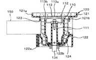
次に、揚送研磨装置100A,100Bの詳細について説明する。ここで2つの揚送研磨装置100A,100Bは同一の構成であるため、以下に揚送研磨装置100Aを代表して説明する。揚送研磨装置100Aは、前記合流樋39より供給された球を揚送するものであり、球の揚送駆動に伴ない球を研磨するための研磨手段も備えている。図1に示すように、揚送研磨装置100Aは、遊技機島1の一端側下部に配設される揚送装置本体101と、揚送パイプ170と、を備えている。  Next, the details of thelift polishing apparatus 100A, 100B will be described. Here, since the twolift polishing apparatuses 100A and 100B have the same configuration, thelift polishing apparatus 100A will be described below as a representative. Thelift polishing apparatus 100A lifts the sphere supplied from theconfluence rod 39, and also includes a polishing means for polishing the sphere as the sphere is driven to lift. As shown in FIG. 1, thelifting polishing apparatus 100 </ b> A includes a lifting apparatusmain body 101 disposed at a lower end on one end side of thegaming machine island 1, and alifting pipe 170.

図6に示すように、揚送装置本体101の外郭をなすハウジング102には、動力により駆動されて遊技球を払い出しつつ揚送させる駆動手段の他、各種関連機構が一体に組み込まれている。ここで駆動手段としては、駆動用歯車110および電動モータ130が該当する。駆動手段は、前記貯留部30における遊技球の貯留量に応じて、制御手段300により駆動が制御されるように設定されており、詳しくは後述する。  As shown in FIG. 6, various related mechanisms are integrally incorporated in ahousing 102 that forms an outline of the lifting apparatusmain body 101, in addition to driving means that is driven by power and lifts a game ball while paying out. Here, thedriving gear 110 and theelectric motor 130 correspond to the driving means. The drive means is set so that the drive is controlled by the control means 300 in accordance with the amount of game balls stored in thestorage section 30, and will be described in detail later.

図7に示すように、揚送装置本体101は、遊技球を歯溝に保持して回転方向へ移送可能な駆動用歯車110と、この駆動用歯車110の外周に沿って配され、遊技球に接して研磨する研磨手段である研磨テープ150とを備えている。駆動用歯車110は樹脂製で略円柱形状に形成され、その内部に空間を有している。駆動用歯車110の内部空間には円柱の軸方向に嵌合部111が設けられ、嵌合部111から内周壁に向かって複数のリブ112が延設されている。  As shown in FIG. 7, the lifting devicemain body 101 is arranged along adriving gear 110 capable of holding a game ball in a tooth gap and transporting it in the rotation direction, and along an outer periphery of thedriving gear 110. And a polishingtape 150 which is a polishing means for polishing in contact with the substrate. Thedrive gear 110 is made of resin and is formed in a substantially cylindrical shape, and has a space inside. Afitting portion 111 is provided in the inner space of thedriving gear 110 in the axial direction of the cylinder, and a plurality ofribs 112 are extended from thefitting portion 111 toward the inner peripheral wall.

図8に示すように、駆動用歯車110の嵌合部111は、メインシャフトである回転軸134に一体に固結されている。駆動用歯車110は、回転軸134の方向が略上下方向になるように配されている。駆動用歯車110の内部空間の上部開口には、キャップ113が固定されている。キャップ113は駆動用歯車110の上面部を構成していて、その頂部113aからその外周縁113bの方へ遊技球を流下させるように略円錐形状に形成されている。図9に示すように、キャップ113の外周縁113bに沿って、駆動用歯車110の案内歯114が形成されている。  As shown in FIG. 8, thefitting portion 111 of thedriving gear 110 is integrally fixed to arotating shaft 134 that is a main shaft. Thedrive gear 110 is arranged so that the direction of therotation shaft 134 is substantially vertical. Acap 113 is fixed to the upper opening of the internal space of thedriving gear 110. Thecap 113 constitutes an upper surface portion of thedriving gear 110 and is formed in a substantially conical shape so that the game ball flows down from thetop portion 113a toward the outerperipheral edge 113b. As shown in FIG. 9, guideteeth 114 of thedriving gear 110 are formed along the outerperipheral edge 113 b of thecap 113.

図10に示すように、略円柱形状の駆動用歯車110の上部は太径部110aとなっており、この太径部110aの外周にも、前記キャップ113の案内歯114が柱面の母線に沿って延びるように形成されている。案内歯114の歯溝114aは、遊技球の半分以上を抱き込むように円弧状断面形状に形成され、その歯溝114aの溝口は、遊技球を歯溝114a内から研磨テープ150側へ離脱不能なように、遊技球の最大径より幅狭に設定されている。  As shown in FIG. 10, the upper portion of the substantiallycylindrical driving gear 110 is alarge diameter portion 110a, and theguide teeth 114 of thecap 113 are also formed on the column surface bus bar on the outer periphery of thelarge diameter portion 110a. It is formed to extend along. Thetooth groove 114a of theguide tooth 114 is formed in an arcuate cross-sectional shape so as to embrace more than half of the game ball, and the groove opening of thetooth groove 114a cannot remove the game ball from thetooth groove 114a to the polishingtape 150 side. As such, the width is set narrower than the maximum diameter of the game ball.

案内歯114の歯溝114aは、その歯溝114aの上端側から入った遊技球を下端側へ案内可能であり、歯溝114aの溝内には、複数の遊技球が上下に重なる状態で順次収容される。また、研磨テープ150は、案内歯114の歯溝114a上端側から下端側へ案内される遊技球に接するように配索されている。  Thetooth groove 114a of theguide tooth 114 can guide the game ball entered from the upper end side of thetooth groove 114a to the lower end side, and a plurality of game balls are sequentially stacked in the groove of thetooth groove 114a. Be contained. Further, the polishingtape 150 is routed so as to be in contact with the game ball guided from the upper end side to the lower end side of thetooth groove 114a of theguide tooth 114.

駆動用歯車110の太径部110aの下側は、外径が徐々に先細りになる縮径部110bとなっている。この縮径部110bの外周には、前記案内歯114に連続して柱面の母線に沿って延びる係止歯115が形成されている。各係止歯115のピッチは、前記各案内歯114の広めのピッチより徐々に狭くなっており、係止歯115の歯溝115a間は、前記案内歯114の歯溝114aから受け入れた遊技球同士を徐々に近づけて接触させるように設定されている。  The lower side of the large-diameter portion 110a of thedriving gear 110 is a reduced-diameter portion 110b whose outer diameter gradually decreases. Lockingteeth 115 are formed on the outer periphery of the reduceddiameter portion 110b so as to extend along the generatrix of the column surface continuously to theguide teeth 114. The pitch of each lockingtooth 115 is gradually narrower than the wider pitch of eachguide tooth 114, and a game ball received from thetooth groove 114 a of the guidingtooth 114 between thetooth grooves 115 a of the lockingtooth 115. It is set so that they come close to each other and come into contact with each other.

縮径部110bの下側は、前記縮径部110bの下端の最小外径と同一外径に延出する細径部110cとなっており、この細径部110cの外周にも、前記案内歯114に連続して柱面の母線に沿って延びる係止歯116が形成されている。係止歯116の歯溝116a間は、前記案内歯114の歯溝114aから案内された遊技球同士を接触させた状態に保つように設定されている。  The lower side of the reduceddiameter portion 110b is asmall diameter portion 110c that extends to the same outer diameter as the minimum outer diameter of the lower end of the reduceddiameter portion 110b. Lockingteeth 116 extending along the generatrix of the column surface are formed continuously to 114. Between thetooth spaces 116a of the lockingteeth 116, the game balls guided from thetooth spaces 114a of theguide teeth 114 are set to be kept in contact with each other.

図7、図6に示すように、駆動用歯車110は、樹脂製の筒体120内に収容されている。筒体120の筒軸は、駆動用歯車110の回転軸134を同一軸としている。筒体120は、上側の上部筒体121と下側の下部筒体122とを一体的に組み合わせてなる。上部筒体121は、前記合流樋39から排出された非整列状態にある遊技球を受け入れて、駆動用歯車110の歯溝114aへ導くものである。また、下部筒体122は、研磨された遊技球を上部筒体121から受け取り、受け取った時の遊技球の整列状態を最適な状態にして外部へ送出可能に形成されるものである。  As shown in FIGS. 7 and 6, thedriving gear 110 is accommodated in aresin cylinder 120. The cylindrical shaft of thecylindrical body 120 has therotation shaft 134 of thedriving gear 110 as the same axis. Thecylinder 120 is formed by integrally combining an upperupper cylinder 121 and a lowerlower cylinder 122. Theupper cylinder 121 receives the non-aligned game balls discharged from the mergingrod 39 and guides them to thetooth groove 114 a of thedriving gear 110. Thelower cylinder 122 is formed so as to be able to receive polished game balls from theupper cylinder 121 and to send the game balls to the outside in an optimal alignment state when the game balls are received.

図8、図6に示すように、上部筒体121は、前記合流樋39の下流端に接続される大径の受け口121aと、駆動用歯車110の案内歯114の外周径にその径を合わせた細径の流出口121bとを有している。上部筒体121の筒壁と下部筒体122の筒壁とに渡って研磨用窓123が開設されている。研磨用窓123は、研磨テープ150を筒体120の外部から内部に進入させ、かつ駆動用歯車110の案内歯114の外周に沿わせて配索できるようになっている。  As shown in FIGS. 8 and 6, theupper cylinder 121 has a diameter that matches the outer diameter of the large-diameter receiving port 121 a connected to the downstream end of thejunction rod 39 and theguide teeth 114 of thedriving gear 110. And a small-diameter outlet 121b. A polishingwindow 123 is opened across the cylinder wall of theupper cylinder 121 and the cylinder wall of thelower cylinder 122. The polishingwindow 123 can be routed along the outer periphery of theguide teeth 114 of thedriving gear 110 by allowing the polishingtape 150 to enter thecylinder 120 from the outside to the inside.

図8に示すように、下部筒体122の下端側は、駆動用歯車110の細径部110c(図10参照)に合わせて、先細りした細径部122aとなっており、この細径部122aの内周壁は、前記細径部110cの係止歯116の外周に沿うように設定されている。また、下部筒体122の細径部122aの底部の中心部には、回転軸134用の軸受け部122bが装着されている。  As shown in FIG. 8, the lower end side of the lowercylindrical body 122 is a small-diameter portion 122 a that is tapered in accordance with the small-diameter portion 110 c (see FIG. 10) of thedriving gear 110, and this small-diameter portion 122 a. The inner peripheral wall is set along the outer periphery of the lockingtooth 116 of the small-diameter portion 110c. A bearingportion 122b for therotating shaft 134 is attached to the center of the bottom portion of thesmall diameter portion 122a of the lowercylindrical body 122.

下部筒体122の内周壁には、前記係止歯116の方へ突出した螺旋状凸部124が凸設されている。螺旋状凸部124は、係止歯116の歯溝116aに受け入れられた遊技球に下方から当接し、遊技球を徐々に下部筒体122の底部に案内可能に形成されている。螺旋状凸部124は、遊技球を下部筒体122の内周壁に沿って螺旋状に約1/4回転した時に、その遊技球の描く軌跡に対応して形成されている。なお、螺旋状凸部124の始端は、次述する連絡用通路125の入口を上方から臨む位置に形成されている。  On the inner peripheral wall of the lowercylindrical body 122, a spiralconvex portion 124 protruding toward the lockingtooth 116 is provided. The spiralconvex portion 124 abuts on the game ball received in thetooth groove 116 a of the lockingtooth 116 from below, and is formed so that the game ball can be gradually guided to the bottom portion of the lowercylindrical body 122. The spiralconvex portion 124 is formed corresponding to a trajectory drawn by the game ball when the game ball is spirally rotated about ¼ along the inner peripheral wall of the lowercylindrical body 122. The starting end of the spiralconvex portion 124 is formed at a position facing the entrance of thecommunication passage 125 described below from above.

図11、図12に示すように、下部筒体122の筒壁には、細径部122aの底部に案内された遊技球を揚送パイプ170へ導くための連絡用通路125が開設されている。揚送パイプ170と連絡用通路125とは、下部筒体122の筒壁に沿って移動する遊技球の円形状軌跡に対して引かれた接線の方向線上に開設されている。  As shown in FIGS. 11 and 12, acommunication passage 125 is provided in the cylindrical wall of the lowercylindrical body 122 to guide the game ball guided to the bottom of thesmall diameter portion 122 a to the liftingpipe 170. . The liftingpipe 170 and thecommunication passage 125 are established on a tangential direction line drawn with respect to the circular locus of the game ball moving along the cylindrical wall of the lowercylindrical body 122.

また、下部筒体122の適所には、揚送すべき遊技球の有無を検出するための残球センサ41A(図1参照)が設けられている。残球センサ41Aは、前述したアウト球センサ40A,40Bと同様に被検出物である遊技球との距離に応じて動作する近接スイッチや磁気センサ等により構成され、信号線を介して制御手段300に接続されている。なお、他方の揚送研磨装置100Bにも、同様に揚送すべき遊技球の有無を検出する残球センサ41Bが配設されている。  Further, a remainingball sensor 41A (see FIG. 1) for detecting the presence / absence of a game ball to be lifted is provided at an appropriate position of the lowercylindrical body 122. The remainingball sensor 41A is configured by a proximity switch, a magnetic sensor, or the like that operates according to the distance from the game ball that is the object to be detected, similarly to the above-described outball sensors 40A and 40B, and the control means 300 via a signal line. It is connected to the. Note that a remainingball sensor 41B that detects the presence or absence of a game ball to be lifted is also disposed in the otherlift polishing apparatus 100B.

図6に示すように、揚送装置本体101のハウジング102の上板端部には、電動モータ130が取り付けられている。電動モータ130には、ギアヘッド131および駆動軸131aが一体に組み付けられている。ギアヘッド131の減速比は、例えば1:25である。駆動軸131aは、その軸方向を上下方向に配されており、下端部に平歯車132が固設されている。電動モータ130としては、具体的には例えばブレーキ付きモータ等が最適である。ここでブレーキ付きモータとは、一般の汎用モータにブレーキ機構を設けたものであり、モータ駆動を急停止させることができるという優れた特性を備えている。なお、ブレーキ付きモータ自体の構成は一般的であるので詳細な説明は省略する。  As shown in FIG. 6, anelectric motor 130 is attached to the upper plate end of thehousing 102 of the lifting apparatusmain body 101. Agear head 131 and adrive shaft 131a are integrally assembled with theelectric motor 130. The reduction ratio of thegear head 131 is, for example, 1:25. Thedrive shaft 131a is arranged with its axial direction in the vertical direction, and aspur gear 132 is fixed to the lower end portion. Specifically, for example, a motor with a brake is optimal as theelectric motor 130. Here, the motor with a brake is a general general-purpose motor provided with a brake mechanism, and has an excellent characteristic that the motor drive can be suddenly stopped. Since the configuration of the motor with brake itself is general, detailed description thereof is omitted.

ハウジング102内の中央部には軸受133が配され、上板の内面側に固設されている。この軸受133によって回転軸134が回転可能に支持されている。回転軸134は、その軸を上下方向にしていて、2枚の平歯車135、136が固設されている。回転軸134側の平歯車136と駆動軸131a側の平歯車132とには、タイミングベルト137が巻き掛けられている。また、ハウジング102内の端部には連動機構140が配設されている。連動機構140は、研磨テープ150の駆動を駆動用歯車110に連動させるものである。連動機構140は、3つのシャフト141〜143と、これら3つのシャフト141〜143を回転可能に支持するための支持ブラケット144とを備えている。  Abearing 133 is disposed at the center of thehousing 102 and is fixed to the inner surface side of the upper plate. Theshaft 133 is rotatably supported by thebearing 133. Therotary shaft 134 has its axis in the vertical direction, and twospur gears 135 and 136 are fixedly provided. Atiming belt 137 is wound around thespur gear 136 on therotating shaft 134 side and thespur gear 132 on thedrive shaft 131a side. In addition, aninterlocking mechanism 140 is disposed at an end in thehousing 102. Theinterlocking mechanism 140 interlocks the driving of the polishingtape 150 with thedriving gear 110. Theinterlocking mechanism 140 includes threeshafts 141 to 143 and asupport bracket 144 for rotatably supporting the threeshafts 141 to 143.

シャフト141の回転は、ウオームギア141aおよび平歯車142aを介してシャフト142に伝わり、さらに、ウオームギア142bおよび平歯車143aを介してシャフト143に伝わる。シャフト141には平歯車141bが固設されている。シャフト141側の平歯車141bと回転軸134側の平歯車135とに、タイミングベルト145が巻き掛けられている。また、シャフト143には、研磨テープ150を繰り込むためのテープローラ146が固設されている。テープローラ146の外周面には、滑り止めのためのローレット目、その他の刻み目が刻設されている。  The rotation of theshaft 141 is transmitted to theshaft 142 via theworm gear 141a and thespur gear 142a, and further transmitted to theshaft 143 via theworm gear 142b and thespur gear 143a. Aspur gear 141 b is fixed to theshaft 141. Atiming belt 145 is wound around aspur gear 141b on theshaft 141 side and aspur gear 135 on therotating shaft 134 side. Further, atape roller 146 for feeding the polishingtape 150 is fixed to theshaft 143. On the outer peripheral surface of thetape roller 146, knurled stitches for preventing slippage and other notches are formed.

図7および図6に示すように、テープローラ146は、連動機構140によって駆動用歯車110の回転軸134に連動するように設定されている。また、テープローラ146は、駆動用歯車110の案内歯114による遊技球の移動速度に応じた速度で、研磨テープ150を収納ケース151から繰り出すと共に、駆動用歯車110の外周に沿って移動するように構成されている。なお、テープローラ146が研磨テープ150を移動する方向は、駆動用歯車110の案内歯114による遊技球の移動方向とは反対の方向になっている。  As shown in FIGS. 7 and 6, thetape roller 146 is set to be interlocked with therotation shaft 134 of thedriving gear 110 by theinterlocking mechanism 140. Further, thetape roller 146 feeds the polishingtape 150 from thestorage case 151 at a speed corresponding to the moving speed of the game ball by theguide teeth 114 of thedriving gear 110 and moves along the outer periphery of thedriving gear 110. It is configured. The direction in which thetape roller 146 moves the polishingtape 150 is opposite to the direction in which the game ball moves by theguide teeth 114 of thedriving gear 110.

ハウジング102の上板には、収納ケース151を嵌脱可能なカセットガイド152が設けられている。図13に示すように、収納ケース151は、研磨テープ150を収容可能なものである。研磨テープ150は、幅34mm、厚み0.4mm、1巻4.5mの不織布である。研磨テープ150は、巻き軸に巻着された状態で収容されている。これに限らず、研磨テープ150は畳まれた状態で収納ケース151に収容されていても良い。収納ケース151の前面部は、装着時に駆動用歯車110の外周に沿うように円弧形の断面形状に形成されている。  On the upper plate of thehousing 102, acassette guide 152 capable of fitting / removing thestorage case 151 is provided. As shown in FIG. 13, thestorage case 151 can store the polishingtape 150. The polishingtape 150 is a nonwoven fabric having a width of 34 mm, a thickness of 0.4 mm, and a roll of 4.5 m. The polishingtape 150 is accommodated in a state of being wound around a winding shaft. Not limited to this, the polishingtape 150 may be stored in thestorage case 151 in a folded state. The front surface portion of thestorage case 151 is formed in an arc-shaped cross-sectional shape so as to follow the outer periphery of thedriving gear 110 when mounted.

収納ケース151の前面部には、クッション部材153が装着されている。クッション部材153は、フェルト等の弾力性のある材料で成形される。研磨テープ150は収納ケース151のガイド溝154を通ってクッション部材153の一端側へ繰り出され、クッション部材153の弾発力で駆動用歯車110側の遊技球を押圧可能な状態で案内歯114の外周に沿うように、クッション部材153の一端側からその他端側へ延ばされ、さらに、クッション部材153の他端側から収納ケース151のガイド溝155を通って繰り込まれるように配索されている。  Acushion member 153 is attached to the front surface of thestorage case 151. Thecushion member 153 is formed of an elastic material such as felt. The polishingtape 150 is fed to one end side of thecushion member 153 through theguide groove 154 of thestorage case 151, and theguide teeth 114 are pressed while the game ball on thedriving gear 110 side can be pressed by the elastic force of thecushion member 153. Along the outer periphery, thecushion member 153 extends from one end side to the other end side, and is further routed from the other end side of thecushion member 153 through theguide groove 155 of thestorage case 151. Yes.

ガイド溝155の先には、キャプスタンローラ156が設けられている。キャプスタンローラ156がテープローラ146に弾発的に当接している。繰り込まれた使用後の研磨テープ150は、キャプスタンローラ156とテープローラ146との間の隙間を通り、収納ケース151に立設された回収筒157(図7参照)の中に入るように配索されている。回収筒157の手前側に、研磨テープ150を回収筒157へ案内するためのガイド部材158が設けられている。  Acapstan roller 156 is provided at the tip of theguide groove 155. Acapstan roller 156 elastically contacts thetape roller 146. The used polishingtape 150 that has been retracted passes through the gap between thecapstan roller 156 and thetape roller 146 so as to enter the collection cylinder 157 (see FIG. 7) standing on thestorage case 151. It has been routed. Aguide member 158 for guiding the polishingtape 150 to therecovery cylinder 157 is provided on the front side of therecovery cylinder 157.

回収筒157を通った研磨テープ150は、所定位置にて回収されるようになっている。本実施の形態では、使用後の研磨テープ150の巻き取りを行わないが、研磨テープ150を巻き取るためのボビン等を設けても良い。なお、カセットガイド152には、収納ケース151を拘束および拘束解除するためのロック機構159(図7参照)も設けられている。  The polishingtape 150 that has passed through thecollection cylinder 157 is collected at a predetermined position. In this embodiment, the used polishingtape 150 is not wound, but a bobbin or the like for winding the polishingtape 150 may be provided. Thecassette guide 152 is also provided with a lock mechanism 159 (see FIG. 7) for restraining and releasing thestorage case 151.

図14および図15に示すように、下部筒体122の連絡用通路125と揚送パイプ170との間には、逆流防止機構160が配されている。逆流防止機構160は、アーム161と、付勢手段162およびシャッタ部材163とを有している。アーム161の基端部161aは、枢軸164により揚送パイプ170の下端部171に揺動可能に枢着されている。アーム161の基端部161aと先端部161bとの間の中間部には、シャッタ部材163が設けられている。枢軸164には付勢手段162である巻きばねが巻着されている。シャッタ部材163には楔形状のゲート部163aが凹設されている。  As shown in FIGS. 14 and 15, abackflow prevention mechanism 160 is disposed between thecommunication passage 125 of the lowercylindrical body 122 and thefeed pipe 170. Thebackflow prevention mechanism 160 includes anarm 161, an urging means 162, and ashutter member 163. Abase end portion 161 a of thearm 161 is pivotally attached to alower end portion 171 of the liftingpipe 170 by apivot 164 so as to be swingable. Ashutter member 163 is provided at an intermediate portion between thebase end portion 161 a and thetip end portion 161 b of thearm 161. A winding spring which is a biasing means 162 is wound around thepivot 164. Theshutter member 163 is recessed with a wedge-shapedgate portion 163a.

シャッタ部材163は、図14に示すように、揚送パイプ170を連絡用通路125に連結した時、付勢手段162の付勢力に抗してアーム161の先端部161bを下部筒体122の当接部122cに乗り上げさせ、アーム161を枢軸164回りに揺動させることで、図15に示すように、シャッタ部材163のゲート部163aを上昇して揚送パイプ170の下端部171側の通路を開く開放位置に揺動する。一方、揚送パイプ170を連絡用通路125から外した時に、アーム161の先端部161bを当接部122cから外して、付勢手段162の付勢力によりアーム161を枢軸164回りに反対方向へ揺動させることで、シャッタ部材163のゲート部163aを下降させて揚送パイプ170の下端部171側の通路を閉じる閉塞位置に揺動する。  As shown in FIG. 14, theshutter member 163 moves thetip 161 b of thearm 161 against thelower cylinder 122 against the urging force of the urging means 162 when thetransport pipe 170 is connected to thecommunication passage 125. By riding on thecontact portion 122c and swinging thearm 161 about thepivot 164, as shown in FIG. 15, thegate portion 163a of theshutter member 163 is raised, and the passage on thelower end portion 171 side of thefeed pipe 170 is moved. Swings to the open open position. On the other hand, when the liftingpipe 170 is removed from thecommunication passage 125, thedistal end portion 161b of thearm 161 is removed from thecontact portion 122c, and thearm 161 is swung around thepivot 164 in the opposite direction by the urging force of the urging means 162. By moving, thegate portion 163a of theshutter member 163 is lowered to swing to the closed position where the passage on thelower end portion 171 side of thefeed pipe 170 is closed.

図6に示すように、前記揚送装置本体101に、下端部171が連通接続された揚送パイプ170は、前記下部筒体122から緩やかに湾曲して立ち上がり上方へ延びている。揚送パイプ170自体の構造は、具体的には例えば、遊技球の直径よりわずかに大きい内径を有し、遊技球を1列に整列させた状態で移送するパイプ部材から構成したり、他に、長手方向に細幅に延びる2枚の溝状断面形状の部材を、その溝同士を合わせ、そのフランジ同士を接合することで、遊技球を通過可能な移送パイプとして形成しても良い。  As shown in FIG. 6, a liftingpipe 170 having alower end portion 171 connected to the lifting devicemain body 101 is gently curved from the lowercylindrical body 122 and extends upward. Specifically, the structure of the liftingpipe 170 itself is constituted by, for example, a pipe member that has an inner diameter slightly larger than the diameter of the game balls and transfers the game balls in a row, Further, two groove-like cross-sectional members extending narrowly in the longitudinal direction may be formed as transfer pipes that can pass the game ball by matching the grooves and joining the flanges.

図1に示すように、揚送パイプ170は上方へ真っ直ぐ延び上がり、その上端部172の先端排出口は、遊技機島1内の一端側の上段部分に配設された上部タンク50に連通接続されている(図4参照)。また、揚送パイプ170の略中間の高さ部位には、当該位置に揚送された遊技球を検出する揚送球センサ42Aが設けられている。  As shown in FIG. 1, the liftingpipe 170 extends straight upward, and the tip discharge port of theupper end portion 172 is connected to theupper tank 50 disposed in the upper stage portion on one end side in thegaming machine island 1. (See FIG. 4). A liftingball sensor 42 </ b> A for detecting a game ball lifted to the position is provided at a substantially intermediate height portion of the liftingpipe 170.

揚送球センサ42Aは、当該部位を通過する球を1個ずつ検出可能なものであり、前述したアウト球センサ40A,40B等と同様に被検出物である遊技球との距離に応じて動作する近接スイッチや磁気センサ等により構成され、信号線を介して制御手段300に接続されている。なお、他方の揚送研磨装置100Bにも、同様に揚送された遊技球を検出する揚送球センサ42Bが配設されている。  Thelift ball sensor 42A can detect the balls passing through the part one by one, and operates according to the distance from the game ball as the detected object, like the above-described outball sensors 40A and 40B. It is configured by a proximity switch, a magnetic sensor, and the like, and is connected to the control means 300 via a signal line. The other lifting /polishing apparatus 100B is also provided with alifting ball sensor 42B for detecting a similarly lifted game ball.

また、遊技機島1の上段部分には、図1,図2,図4に示すように、前記上部タンク50や補給樋51等が配設されている。上部タンク50の底面部には、前述した揚送パイプ170の上端部172の先端排出口が連通されている他、補給樋51の上流端が接続されている。さらに上部タンク50の底面部には、補給樋51が遊技球で満杯になった際に、余分な球を下方へ落下させるオーバーフローホース52の球入口も連通されている。オーバーフローホース52は、そのまま下方へ向かい垂下し、その球出口は、前記共有樋32の上流端に球を受け渡すホッパ53に連通されている。  Further, as shown in FIGS. 1, 2, and 4, theupper tank 50, thereplenishment rod 51, and the like are disposed in the upper part of thegaming machine island 1. To the bottom surface of theupper tank 50, the upstream discharge port of theupper end 172 of the above-mentionedfeed pipe 170 is connected, and the upstream end of thereplenishment rod 51 is connected. In addition, the bottom of theupper tank 50 is also connected to a ball inlet of anoverflow hose 52 that drops an extra ball downward when thereplenishment basket 51 is full of game balls. Theoverflow hose 52 hangs downward as it is, and its ball outlet communicates with ahopper 53 that delivers a ball to the upstream end of thecommon rod 32.

補給樋51は、遊技機島1の他端側に向かって下方へ傾斜するように配設されており、補給樋51の途中には、真下に位置する遊技機10に対応して遊技球を整列させた状態で落下させるシュート54が配設されている。シュート54と遊技機10とは、落下する遊技球を導くジャバラ55により連通している。さらに補給樋51の上流端側には、各遊技機10に補給されずに補給樋51の上流端側まで貯まった球を検出するための満杯センサ43が設けられている。満杯センサ43は、前述したアウト球センサ40A,40Bと同様に被検出物である遊技球との距離に応じて動作する近接スイッチや磁気センサ等により構成され、信号線を介して制御手段300に接続されている。  Thereplenishment basket 51 is disposed so as to incline downward toward the other end of thegaming machine island 1, and in the middle of thereplenishment basket 51, a game ball corresponding to thegaming machine 10 located directly below is provided. Achute 54 is provided for dropping in an aligned state. Thechute 54 and thegaming machine 10 communicate with each other by abellows 55 that guides a falling game ball. Further, afull sensor 43 is provided on the upstream end side of the replenishingbasket 51 for detecting balls that have not been replenished to eachgaming machine 10 and have accumulated up to the upstream end side of the replenishingbowl 51. Thefull sensor 43 is configured by a proximity switch, a magnetic sensor, or the like that operates according to the distance from the game ball that is the object to be detected, similar to the above-described outball sensors 40A and 40B, and is connected to the control means 300 via a signal line. It is connected.

次に、遊技機島1の制御手段300について説明する。制御手段300は、遊技機島1に含まれる前述したような揚送研磨装置100A,100B等の動作を集中的に管理するものであり、具体的には、インターフェース、CPU,ROM,RAM等を具備したマイクロコンピュータから成る。制御手段300は、専用のケースに納められ、外部からのゴミの他、静電気や電気ノイズからも保護された状態で、遊技機島1内部の適所に配設されている。  Next, the control means 300 of thegaming machine island 1 will be described. The control means 300 centrally manages the operations of the above-describedlift polishing apparatuses 100A, 100B, etc. included in thegaming machine island 1, and specifically includes an interface, a CPU, a ROM, a RAM, and the like. It consists of a built-in microcomputer. The control means 300 is housed in a dedicated case, and is disposed at a suitable location inside thegaming machine island 1 in a state protected from static electricity and electrical noise in addition to dust from the outside.

図16に示すように、制御手段300には、2つの揚送研磨装置100A,100Bの他、前述した各種センサ40A,40B,41A,41B,42A,42B,43、それに各種情報を表示可能なディスプレイである表示部310が、それぞれ信号線を介して接続されている。また図示省略したが、制御手段300は、遊技場の関係者が管理するホールコンピュータ等とも接続されており、前記表示部310は、ホールコンピュータの周辺機器であっても良い。  As shown in FIG. 16, the control means 300 can display the above-describedvarious sensors 40A, 40B, 41A, 41B, 42A, 42B, 43 and various information in addition to the twolift polishing apparatuses 100A, 100B. Adisplay unit 310 that is a display is connected to each other via a signal line. Although not shown, the control means 300 may also be connected to a hall computer or the like managed by a person related to the game hall, and thedisplay unit 310 may be a peripheral device of the hall computer.

このような制御手段300は、貯留部30における遊技球の貯留量に応じて、各揚送研磨装置100A,100Bの何れかの駆動を制御することにより、貯留部30内の遊技球を遊技機10側へ適量供給する機能、各揚送研磨装置100A,100Bをそれぞれの優先順位に従い順次駆動させる機能、各揚送研磨装置100A,100Bにより揚送された遊技球の数が、研磨テープ150の交換時期として予め定められた所定数に達した時に、その旨を報知手段となる表示部310を介して報知する機能を有している。  Such a control means 300 controls the driving of each of the lifting and polishingapparatuses 100A and 100B in accordance with the amount of game balls stored in thestorage unit 30, thereby allowing the game balls in thestorage unit 30 to be used as gaming machines. The function of supplying an appropriate amount to the 10 side, the function of sequentially driving each of the lifting and polishingapparatuses 100A and 100B according to the respective priorities, and the number of game balls lifted by each of the lifting and polishingapparatuses 100A and 100B When a predetermined number of replacement times is reached, it has a function of notifying that effect via thedisplay unit 310 serving as notification means.

さらに制御手段300は、貯留部30に遊技球が貯留されているにも関わらず、駆動中の揚送研磨装置100A,100Bに遊技球が供給されていない場合には、揚送研磨装置100A,100Bの駆動を停止させると共に、このような事態を警告手段でもある表示部310を介して警告する機能、揚送研磨装置100A,100Bが駆動中であるにも関わらず、該揚送研磨装置100A,100Bに供給されている遊技球が揚送されていない場合には、揚送研磨装置100A,100Bの駆動を停止させると共に、このような事態を同じく表示部310を介して警告する機能等も有している。制御手段300により実現されるこれらの機能に関して詳しくは後述する。  Further, when the game ball is stored in thestorage unit 30 and the game ball is not supplied to the driving andpolishing apparatuses 100A and 100B that are being driven, thecontrol unit 300 is configured to perform the lifting and polishingapparatus 100A, The function of stopping the driving of 100B and warning the situation via thedisplay unit 310 which is also a warning means, thelifting polishing apparatus 100A, even though thelifting polishing apparatuses 100A and 100B are being driven. , 100B, when the game ball is not lifted, the driving andpolishing apparatuses 100A, 100B are stopped and the function of warning such a situation via thedisplay unit 310 is also provided. Have. Details of these functions realized by the control means 300 will be described later.

以下に、遊技機島1における作用について説明する。
先ず、遊技機島1内における遊技球の流れの概要を説明する。図5において、カードユニット20のカード挿入口21に遊技者が有価価値カードを差し込み、貸出ボタン23により投入金額を指定することで、金額に応じた所定数の貸球が上受け皿14へ払い出される。遊技者がハンドル16を回転操作すると、上受け皿14内の遊技球は遊技盤13上に1つずつ打ち出される。各種入賞口に打球が入賞すると、それぞれの入賞口ごとに割り当てられた所定数の賞球が、同じく上受け皿14へ払い出される。
Below, the effect | action in thegaming machine island 1 is demonstrated.
First, an outline of the flow of game balls in thegaming machine island 1 will be described. In FIG. 5, when a player inserts a valuable card into thecard insertion slot 21 of thecard unit 20 and designates an insertion amount with thelending button 23, a predetermined number of balls according to the amount are paid out to theupper tray 14. . When the player rotates thehandle 16, the game balls in theupper tray 14 are launched one by one on thegame board 13. When a hit ball wins various winning holes, a predetermined number of winning balls assigned to each winning hole are similarly paid out to theupper tray 14.

遊技盤13上に打ち出された遊技球は、遊技盤13の背面側に集められて計数処理された後、アウト球誘導樋31上に排出されて貯留部30にアウト遊技球として回収され、アウト球誘導樋31の下流端に連なるアウト球通路33を落下して、分配通路34により一対のアウト球回収樋35A,35Bに分配されて流下する。分配通路34により、アウト球回収樋35Bよりもアウト球回収樋35Aの方へ、より多くの球が優先して分配されて流下する。  The game balls launched on thegame board 13 are collected on the back side of thegame board 13 and counted, and then discharged onto the out ball guidebar 31 and collected in thestorage unit 30 as out game balls. The outball passage 33 connected to the downstream end of the ball guiderod 31 is dropped and distributed to the pair of outball collection rods 35A and 35B by thedistribution passage 34 and flows down. By thedistribution passage 34, more balls are distributed and flowed down in preference to the outball collection basket 35A than to the outball collection basket 35B.

また、上部タンク50から溢れ出てオーバーフローホース52を落下してきた遊技球は、ホッパ53を介して共有樋32に導入され、共有樋32を落下して、貯留球樋36に導入されて流下する。貯留球樋36よりも前記各アウト球回収樋35A,35Bの方が急勾配になっており、各アウト球回収樋35A,35B上の球の方が、貯留球樋36上の球よりもより速く流下する。  The game balls overflowing from theupper tank 50 and falling on theoverflow hose 52 are introduced into the sharedbasket 32 through thehopper 53, fall on the sharedbasket 32, and are introduced into thestorage ball basket 36 and flow down. . Each of the outball collection baskets 35A and 35B is steeper than thestorage ball basket 36, and the spheres on the outball collection baskets 35A and 35B are more than the balls on thestorage bulb basket 36. It flows down quickly.

図3に示すように、各アウト球回収樋35A,35Bおよび貯留球樋36を流下してきた球は、それぞれ異物除去部37によって異物が取り除かれた後、合流樋39を介して2つの揚送研磨装置100A,100Bへほぼ均等に分配されて供給される。合流樋39の両側では、それぞれ貯留球樋36から分配される球よりも、各アウト球回収樋35A,35Bから分配される球の方が、両側の揚送研磨装置100A,100Bへ優先して供給される。  As shown in FIG. 3, the spheres that have flowed down the out ball collection baskets 35 </ b> A and 35 </ b> B and thestorage bulb basket 36 are removed by the foreignsubstance removal unit 37, and then are transferred to the two through thejunction basket 39. It is distributed and supplied almost evenly to the polishingapparatuses 100A and 100B. On both sides of theconfluence basin 39, the spheres distributed from the respective outsphere collection basins 35A and 35B have priority over the feeding and polishingapparatuses 100A and 100B on both sides, rather than the spheres distributed from thestorage spheres 36 respectively. Supplied.

このようにアウト球は、各アウト球回収樋35A,35Bの下流端から上流端側へと徐々に貯まる。そしてアウト球センサ40A,40Bの位置まで球が滞留すると、各アウト球センサ40A,40Bから検出信号が出力される。制御手段300は、各アウト球センサ40A,40Bからの検出信号に基づいて、貯留部30における遊技球の貯留量を判断し、揚送研磨装置100A,100Bの駆動を制御する。  In this way, the out balls are gradually stored from the downstream end to the upstream end side of each outball collection basket 35A, 35B. When the sphere stays at the position of theout sphere sensors 40A and 40B, detection signals are output from theout sphere sensors 40A and 40B. The control means 300 determines the amount of game balls stored in thestorage unit 30 based on the detection signals from the out-ball sensors 40A and 40B, and controls the driving of the lifting and polishingapparatuses 100A and 100B.

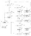
次に、制御手段300による遊技球の揚送動作の制御について説明する。図17は、遊技球の揚送に関する処理を説明するフローチャートである。図17において、制御手段300は、最初に補給樋51にある満杯センサ43からの検出信号の有無により、遊技機島1の上段部分における球の貯留量を判断する(S101)。ここで、満杯センサ43からの検出信号を入力した場合には(S101;YES)、続いて各アウト球回収樋35A,35Bのうち、球が優先的に流下する方のアウト球回収樋35Aにあるアウト球センサ40Aからの検出信号の有無により、貯留部30における球の貯留量を判断する(S102)。  Next, the control of the game ball lifting operation by the control means 300 will be described. FIG. 17 is a flowchart for explaining processing related to the lifting of a game ball. In FIG. 17, the control means 300 first determines the amount of balls stored in the upper part of thegaming machine island 1 based on the presence / absence of a detection signal from thefull sensor 43 in the replenishment basket 51 (S101). Here, when the detection signal from thefull sensor 43 is input (S101; YES), subsequently, out of the outball collection baskets 35A and 35B, the outball collection basket 35A on which the ball flows down preferentially. Based on the presence or absence of a detection signal from a certain out-ball sensor 40A, the amount of balls stored in thestorage unit 30 is determined (S102).

アウト球センサ40Aからの検出信号の入力がない場合には(S102;NO)、制御手段300は、アウト球センサ40Aからの球を主に受け入れる揚送研磨装置100Aの駆動を停止させて(S103)、最初の処理に戻る。このように、既に遊技機島1の上段部分に十分な量の遊技球があり、貯留部30内のアウト球回収樋35Aに球がさほど貯留されていないような場合には、揚送研磨装置100Aの不必要な駆動を防止することができる。  When there is no detection signal input from the out-sphere sensor 40A (S102; NO), thecontrol unit 300 stops driving the lifting and polishingapparatus 100A that mainly receives the sphere from the out-sphere sensor 40A (S103). ) And return to the first process. Thus, when there is already a sufficient amount of game balls in the upper part of thegaming machine island 1 and the balls are not so much stored in the out-ball collecting basket 35A in thestorage unit 30, the lift polishing apparatus Unnecessary driving of 100A can be prevented.

また、前記満杯センサ43からの検出信号の入力がない場合(S101;NO)や、前記アウト球センサ40Aからの検出信号の入力があった場合(S102;YES)には、今度は揚送研磨装置100Aにある残球センサ41Aからの検出信号の有無により、揚送研磨装置100Aにおいて揚送すべき球の有無を判断する(S106)。  Further, when there is no detection signal input from the full sensor 43 (S101; NO), or when there is a detection signal input from the out-ball sensor 40A (S102; YES), this time the lift polishing is performed. Based on the presence / absence of a detection signal from the remainingball sensor 41A in theapparatus 100A, the presence / absence of a ball to be lifted in the lifting and polishingapparatus 100A is determined (S106).

残球センサ41Aからの検出信号の入力がない場合(S106;NO)、制御手段300は揚送研磨装置100Aの駆動を停止させると共に、揚送研磨装置100Aに遊技球が供給されていない事態を、表示部310によるエラー表示によって遊技場の関係者に警告して(S113)、最初の処理に戻る。また表示部310と共に、あるいは表示部310に代えて、ホールコンピュータ側の表示部により前記エラー表示による警告をしたり、さらに印刷ないし音声により警告しても良い。  When there is no input of a detection signal from the remainingball sensor 41A (S106; NO), thecontrol unit 300 stops driving thelift polishing apparatus 100A, and the game ball is not supplied to thelift polishing apparatus 100A. Then, an error display on thedisplay unit 310 warns the people involved in the game hall (S113), and the process returns to the first process. In addition to thedisplay unit 310 or in place of thedisplay unit 310, a warning by the error display may be given by a display unit on the hall computer side, or a warning may be given by printing or voice.

残球センサ41Aからの検出信号の入力があった場合(S106;YES)、制御手段300は揚送研磨装置100Aを駆動させる(S107)。続いて、揚送パイプ170にある揚送球センサ42Aからの検出信号の有無により、揚送研磨装置100Aの駆動に伴ない実際に問題なく遊技球が揚送されているか否かを判断する(S108)。  When a detection signal is input from the remainingball sensor 41A (S106; YES), the control means 300 drives thelift polishing apparatus 100A (S107). Subsequently, based on the presence or absence of a detection signal from the liftedball sensor 42A in the liftedpipe 170, it is determined whether or not the game ball is actually lifted without any problem as thelift polishing apparatus 100A is driven (S108). ).

揚送球センサ42Aからの検出信号の入力がない場合には(S108;NO)、制御手段300は揚送研磨装置100Aの駆動を停止させると共に、揚送研磨装置100Aが駆動しても遊技球が揚送されていない事態を、表示部310により電動モータ130の故障等の異常を遊技場の関係者に警告する(S114)。この時点では、未だ最初の処理に戻ることなく、後述する揚送研磨装置100Bの駆動に関する処理に移行するため、一方の揚送研磨装置100Aで不具合が生じても、もう一方の揚送研磨装置100Bにより、遊技球の揚送を補うことができる。  When no detection signal is input from the liftedball sensor 42A (S108; NO), the control means 300 stops driving the lifted polishingapparatus 100A, and the game ball is not moved even if the lifted polishingapparatus 100A is driven. Thedisplay unit 310 warns the abnormality of theelectric motor 130 to the person concerned at the game hall about the situation where it is not lifted (S114). At this time, since the process proceeds to the process related to driving of thelift polishing apparatus 100B described later without returning to the first process, even if a problem occurs in onelift polishing apparatus 100A, the otherlift polishing apparatus 100B can supplement the lifting of the game ball.

揚送研磨装置100Aの電動モータ130の異常に関する警告は、表示部310と共に、あるいは表示部310に代えて、ホールコンピュータ側の表示部により警告したり、さらに印刷ないし音声により警告しても良い。揚送球センサ42Aからの検出信号の入力があった場合(S108;YES)、揚送研磨装置100Aは正常に駆動していると判断される。  The warning regarding the abnormality of theelectric motor 130 of the lifting and polishingapparatus 100A may be warned by the display unit on the hall computer side together with thedisplay unit 310 or in place of thedisplay unit 310, or by printing or voice. When a detection signal is input from thelift ball sensor 42A (S108; YES), it is determined that thelift polishing apparatus 100A is normally driven.

続いて制御手段300は、揚送研磨装置100Aにおいて今まで揚送された遊技球の数を検出する(S104)。ここで検出されたカウント値が、揚送研磨装置100Aにおける研磨テープ150の交換時期として予め定められた所定数(例えば400万個)に達した時には(S104;YES)、研磨テープ150が消耗した旨を表示部310によるアラーム表示によって遊技場の関係者に報知する(S105)。また表示部310と共に、あるいは表示部310に代えて、ホールコンピュータ側の表示部により報知したり、さらに印刷ないし音声により報知しても良い。  Subsequently, the control means 300 detects the number of game balls that have been lifted so far in thelift polishing apparatus 100A (S104). When the detected count value reaches a predetermined number (for example, 4 million) determined in advance as the replacement time of the polishingtape 150 in thelift polishing apparatus 100A (S104; YES), the polishingtape 150 is consumed. A notice to the effect is given to the person concerned at the game hall by an alarm display on the display unit 310 (S105). Further, it may be notified together with thedisplay unit 310 or instead of thedisplay unit 310 by a display unit on the hall computer side, or may be notified by printing or voice.

次に制御手段300は、前記揚送された遊技球の数の検出に関する処理とは別に、前記各アウト球回収樋35A,35Bのうち、もう一方のアウト球回収樋35Bにあるアウト球センサ40Bからの検出信号の有無により、貯留部30における球の貯留量を判断する(S109)。ここでアウト球センサ40Bからの検出信号の入力がない場合には(S109;NO)、制御手段300は、アウト球センサ40Bからの球を主に受け入れる揚送研磨装置100Bの駆動を停止させて(S115)、最初の処理に戻る。それにより、前記揚送研磨装置100Aの駆動だけで十分な量の遊技球を揚送できたり、既に遊技機島1の上段部分に十分な量の遊技球があるような場合には、揚送研磨装置100Bの不必要な駆動を防止することができる。  Next, the control means 300, apart from the processing relating to the detection of the number of lifted game balls, outball sensor 40B in the other outball collection basket 35B out of each of the outball collection baskets 35A, 35B. The amount of stored spheres in thestorage unit 30 is determined based on the presence or absence of a detection signal from (S109). If there is no detection signal input from the out-sphere sensor 40B (S109; NO), the control means 300 stops driving the lifting and polishingapparatus 100B that mainly receives the sphere from the out-sphere sensor 40B. (S115), the process returns to the first process. As a result, when a sufficient amount of game balls can be lifted only by driving thelift polishing apparatus 100A, or when there is a sufficient amount of game balls already in the upper part of thegaming machine island 1, Unnecessary driving of thepolishing apparatus 100B can be prevented.

一方、前記アウト球センサ40Bからの検出信号の入力があった場合(S109;YES)、今度は揚送研磨装置100Bにある残球センサ41Bからの検出信号の有無により、揚送研磨装置100Bにおける揚送すべき球の有無を判断する(S110)。
ここで残球センサ41Bからの検出信号の入力がない場合(S110;NO)、制御手段300は揚送研磨装置100Bの駆動を停止させると共に、揚送研磨装置100Bに遊技球が供給されていない事態を、表示部310によるエラー表示によって遊技場の関係者に警告して(S116)、最初の処理に戻る。また表示部310と共に、あるいは表示部310に代えて、ホールコンピュータ側の表示部により警告したり、さらに印刷ないし音声により警告しても良い。
On the other hand, when a detection signal is input from the out-ball sensor 40B (S109; YES), this time, the presence or absence of a detection signal from the remainingball sensor 41B in the lifting and polishingapparatus 100B determines whether the detected signal is in the lifting and polishingapparatus 100B. It is determined whether or not there is a ball to be lifted (S110).
Here, when no detection signal is input from the remainingball sensor 41B (S110; NO), the control means 300 stops driving thelift polishing apparatus 100B and no game ball is supplied to thelift polishing apparatus 100B. The situation is warned by the error display on thedisplay unit 310 to the people in the game hall (S116), and the process returns to the first process. Further, a warning may be given with a display unit on the hall computer side together with thedisplay unit 310 or in place of thedisplay unit 310, or a warning may be given by printing or voice.

残球センサ41Bからの検出信号の入力があった場合(S110;YES)、制御手段300は揚送研磨装置100Bを駆動させる(S111)。続いて、揚送パイプ170にある揚送球センサ42Bからの検出信号の有無により、揚送研磨装置100Bの駆動に伴ない実際に問題なく遊技球が揚送されているか否かを判断する(S112)。  When a detection signal is input from the remainingball sensor 41B (S110; YES), the control means 300 drives thelift polishing apparatus 100B (S111). Subsequently, based on the presence or absence of a detection signal from the liftedball sensor 42B in the liftedpipe 170, it is determined whether or not the game ball is actually lifted without any problem as thelift polishing apparatus 100B is driven (S112). ).

揚送球センサ42Bからの検出信号の入力がない場合には(S112;NO)、制御手段300は揚送研磨装置100Bの駆動を停止させると共に、揚送研磨装置100Bが駆動しても遊技球が揚送されていない事態を、表示部310により電動モータ130の故障等の異常を遊技場の関係者に警告する(S117)。この時点で一旦処理は終了する。これは処理が継続して自動復旧を行うと、電動モータ130の故障が悪化する可能性があるためである。揚送研磨装置100Bの電動モータ130の異常に関する警告は、表示部310と共に、あるいは表示部310に代えて、ホールコンピュータ側の表示部により警告したり、さらに印刷ないし音声により警告しても良い。
一方、揚送球センサ42Bからの検出信号の入力があった場合(S112;YES)、揚送研磨装置100Bは正常に駆動していると判断される。
If no detection signal is input from the liftedball sensor 42B (S112; NO), the control means 300 stops driving the lifted polishingapparatus 100B, and the game ball is not moved even if the lifted polishingapparatus 100B is driven. Thedisplay unit 310 warns the abnormality of theelectric motor 130 to the person concerned at the game hall about the situation that the vehicle is not lifted (S117). At this point, the process is temporarily terminated. This is because the failure of theelectric motor 130 may worsen if the process continues and automatic recovery is performed. The warning regarding the abnormality of theelectric motor 130 of the lifting and polishingapparatus 100B may be warned by a display unit on the hall computer side together with thedisplay unit 310 or in place of thedisplay unit 310, or by printing or voice.
On the other hand, when a detection signal is input from the liftedball sensor 42B (S112; YES), it is determined that thelift polishing apparatus 100B is operating normally.

続いて制御手段300は、揚送研磨装置100Bにおいて今まで揚送された遊技球の数を検出する(S104)。ここで検出されたカウント値が、揚送研磨装置100Bにおける研磨テープ150の交換時期として予め定められた所定数(例えば400万個)に達した時には(S104;YES)、前記揚送研磨装置100Aの場合と同様に、研磨テープ150が消耗した旨を表示部310によるアラーム表示によって遊技場の関係者に報知する(S105)。また表示部310と共に、あるいは表示部310に代えて、ホールコンピュータ側の表示部により報知したり、さらに印刷ないし音声により報知しても良い。  Subsequently, the control means 300 detects the number of game balls that have been lifted so far in thelift polishing apparatus 100B (S104). When the count value detected here reaches a predetermined number (for example, 4 million) determined in advance as the replacement time of the polishingtape 150 in thelift polishing apparatus 100B (S104; YES), thelift polishing apparatus 100A. In the same manner as in the case of the above, the person concerned in the game hall is notified by an alarm display by thedisplay unit 310 that the polishingtape 150 is consumed (S105). Further, it may be notified together with thedisplay unit 310 or instead of thedisplay unit 310 by a display unit on the hall computer side, or may be notified by printing or voice.

以上のように、前記制御手段300は、貯留部30における遊技球の貯留量に応じて(S102,S109)、各揚送研磨装置100A,100Bの駆動を制御することにより(S103,S107,S111,S115)、貯留部30内の遊技球を遊技機10側へ適量供給する。これにより、各揚送研磨装置100A,100Bを過剰に駆動することなく、遊技機10に適切な量の遊技球を過不足なく供給することができる。特に揚送する遊技球の量に応じて、正確に揚送研磨装置100A,100Bの揚送力を制御することができる。  As described above, thecontrol unit 300 controls the driving of the lifting and polishingapparatuses 100A and 100B (S103, S107, S111) according to the amount of game balls stored in the storage unit 30 (S102, S109). , S115), an appropriate amount of game balls in thestorage unit 30 are supplied to thegaming machine 10 side. As a result, an appropriate amount of game balls can be supplied to thegaming machine 10 without excess or deficiency without excessively driving the lifting and polishingapparatuses 100A and 100B. In particular, the lifting force of the lifting and polishingapparatuses 100A and 100B can be accurately controlled according to the amount of game balls to be lifted.

このように、制御手段300の制御対象は、1つのみではなく2つの揚送研磨装置100A,100Bであるため、各揚送研磨装置100A,100Bの駆動の制御が1つに偏ることなく複数に分散されることになるから、各揚送研磨装置100A,100Bにおける過負荷の集中がなくなり、それぞれ耐久性を向上させることも可能となる。また前述したように、一方の揚送研磨装置100Aで不具合が生じても、もう一方の揚送研磨装置100Bにより、遊技球の揚送を補うことができる。  Thus, since the control object of the control means 300 is not only one but twolift polishing apparatuses 100A and 100B, a plurality of drive controls of thelift polishing apparatuses 100A and 100B are not biased to one. Therefore, the overload concentration in each of thelift polishing apparatuses 100A and 100B is eliminated, and the durability can be improved. In addition, as described above, even if a problem occurs in one lifting and polishingapparatus 100A, the other lifting and polishingapparatus 100B can compensate for the lifting of the game ball.

しかも、各揚送研磨装置100A,100Bには、それぞれ駆動する順番に関する優先順位が予め定められており、制御手段300は、先ず揚送研磨装置100Aの方を駆動制御し、次に揚送研磨装置100Bの方を駆動制御するので、各揚送研磨装置100A,100Bの駆動が特定の一方のみに偏ることがなく、駆動されない方の各揚送研磨装置100A,100Bにおいて遊技球が長く滞留するような事態も防止することができる。  Moreover, each of thelift polishing apparatuses 100A and 100B has a predetermined priority order for driving order, and the control means 300 first drives and controls thelift polishing apparatus 100A, and then lift polishing. Since the driving of theapparatus 100B is controlled, the driving of each of the lifting and polishingapparatuses 100A and 100B is not biased to a specific one, and the game ball stays longer in each of the lifting and polishingapparatuses 100A and 100B that are not driven. Such a situation can also be prevented.

また、前記制御手段300は、各揚送研磨装置100A,100Bにより揚送された遊技球の数が、研磨テープ150の交換時期として予め定められた所定数(例えば400万個)に達した時に(S104;YES)、その旨を表示部310を介して報知するので(S105)、研磨テープ150の汚れ度合いを、揚送および研磨した遊技球の数に関連付けて正確に把握することができる。しかも、表示部310によって自動的に報知することにより、研磨テープ150の交換時期を徒過することなく、汚れた研磨テープ150を確実かつ容易に新たなものと交換することができる。  Further, the control means 300 determines that when the number of game balls lifted by the lifting /polishing apparatuses 100A and 100B reaches a predetermined number (for example, 4 million) determined in advance as the replacement time of the polishingtape 150. (S104; YES), the fact is notified via the display unit 310 (S105), so that the degree of contamination of the polishingtape 150 can be accurately grasped in association with the number of game balls that have been lifted and polished. In addition, by automatically notifying thedisplay unit 310, thedirty polishing tape 150 can be reliably and easily replaced with a new one without passing the replacement time of the polishingtape 150.

また、前記制御手段300は、貯留部30に遊技球が貯留されているにも関わらず(S102;YES,S109;YES)、揚送研磨装置100A,100Bに遊技球が供給されていない場合には(S106;NO,S110;NO)、貯留部30と揚送研磨装置100A,100Bとの間における球詰まり等の不具合が生じたと判断し、揚送研磨装置100A,100Bの無駄な駆動を自動的に停止させることができ、しかも異常事態の発生を自動的に警告することにより(S113,S116)、遊技場の従業員等の関係者に対して迅速に知らしめることができる。  Further, the control means 300 is used when the game balls are not stored in the storage unit 30 (S102; YES, S109; YES), but no game balls are supplied to the lifting and polishingapparatuses 100A and 100B. (S106; NO, S110; NO), it is determined that a defect such as a ball clogging has occurred between thestorage unit 30 and thelift polishing apparatus 100A, 100B, and wasteful driving of thelift polishing apparatuses 100A, 100B is automatically performed. In addition, by automatically warning the occurrence of an abnormal situation (S113, S116), it is possible to promptly notify related parties such as employees of the game hall.

さらに、前記制御手段300は、揚送研磨装置100A,100Bが駆動中であるにも関わらず(S107,S111)、遊技球が揚送されていない場合には(S108;NO,S112;NO)、揚送研磨装置100A,100Bにおいて例えば電動モータ130の作動の異常が生じたと判断し、揚送研磨装置100A,100Bの駆動を自動的に停止させることができ、しかも異常事態の発生を自動的に警告することにより(S114,S117)、遊技場の従業員等の関係者に対して迅速に知らしめることができる。  Further, the control means 300, when the lifting and polishingapparatus 100A, 100B is being driven (S107, S111), when the game ball is not being lifted (S108; NO, S112; NO) For example, it is determined that an abnormality in the operation of theelectric motor 130 has occurred in the lifting and polishingapparatuses 100A and 100B, and the driving of the lifting and polishingapparatuses 100A and 100B can be automatically stopped, and the occurrence of an abnormal situation is automatically performed. By warning (S114, S117), it is possible to promptly inform relevant parties such as game hall employees.

また、貯留部30では、遊技機10から排出されたアウト遊技球を各回収樋35A,35Bに受け入れることにより、一般に汚れ度合いが高いアウト遊技球を他の遊技球から分離した状態で貯留しておくことが可能となる。それにより、他の遊技球と分離されたアウト遊技球を、優先的に研磨処理することが可能となる。特に本実施の形態では、各回収樋35A,35Bに設けたアウト球センサ40A,40Bからの検出信号に基づき、貯留部30における遊技球の貯留量を判断するので、優先的に研磨処理したいアウト遊技球の貯まり具合を基準として、このアウト遊技球を迅速に研磨ないし揚送することができる。  In addition, thestorage unit 30 receives the out game balls discharged from thegaming machine 10 in therespective collection baskets 35A and 35B, thereby storing the out game balls that are generally highly contaminated in a state of being separated from the other game balls. It becomes possible to leave. Thereby, it is possible to preferentially polish out game balls separated from other game balls. In particular, in the present embodiment, the amount of game balls stored in thestorage unit 30 is determined based on detection signals from theout ball sensors 40A and 40B provided in thecollection baskets 35A and 35B. The out-game balls can be quickly ground or lifted based on the amount of game balls stored.

次に、揚送研磨装置100A,100Bにおける揚送ないし研磨動作の詳細についても説明する。以下、揚送研磨装置100Aを代表して説明する。図3において、貯留部30より合流樋39を介して供給される遊技球は、図8に示す揚送研磨装置100Aの上部筒体121の受け口121aに流入し、上部筒体121の流出口121bに向かってさらに流下する。すると遊技球は、流出口121bの中心部に位置する駆動用歯車110のキャップ113に流れ込む。キャップ113は略円錐形状に形成されているので、遊技球はキャップ113の頂部113aから外周縁113bへ流下する。  Next, details of the lifting or polishing operation in the lifting and polishingapparatuses 100A and 100B will be described. Hereinafter, thelift polishing apparatus 100A will be described as a representative. In FIG. 3, the game balls supplied from thestorage unit 30 via thejunction rod 39 flow into the receivingport 121a of the uppercylindrical body 121 of the lifting and polishingapparatus 100A shown in FIG. 8, and theoutlet 121b of the uppercylindrical body 121. It will flow further down. Then, the game ball flows into thecap 113 of thedriving gear 110 located at the center of theoutlet 121b. Since thecap 113 is formed in a substantially conical shape, the game ball flows down from the top 113a of thecap 113 to the outerperipheral edge 113b.

図9に示すように、キャップ113の外周に沿って、駆動用歯車110の案内歯114が配されているので、遊技球は、案内歯114の歯溝114aの上端側に向かって流下する。案内歯114の歯溝114aの上端側が遊技球を入れていない凹の状態であれば、遊技球は、凹の状態にある案内歯114の歯溝114aの上端側に入ることができる。案内歯114の歯溝114aの上端側に入った遊技球は、その自重で案内歯114の歯溝114aの下端側へ移動する。遊技球が案内歯114の歯溝114aの下端側へ移動すると、案内歯114の歯溝114aの上端側は凹の状態になる。この凹の状態にある案内歯114の歯溝114aの上端側に新たな遊技球が入ることができる。  As shown in FIG. 9, since theguide teeth 114 of thedriving gear 110 are arranged along the outer periphery of thecap 113, the game ball flows down toward the upper end side of thetooth groove 114 a of theguide teeth 114. If the upper end side of thetooth groove 114a of theguide tooth 114 is in a concave state where no game ball is inserted, the game ball can enter the upper end side of thetooth groove 114a of theguide tooth 114 in the concave state. The game ball that has entered the upper end side of thetooth groove 114a of theguide tooth 114 moves to the lower end side of thetooth groove 114a of theguide tooth 114 by its own weight. When the game ball moves to the lower end side of thetooth groove 114a of theguide tooth 114, the upper end side of thetooth groove 114a of theguide tooth 114 becomes concave. A new game ball can enter the upper end side of thetooth groove 114a of theguide tooth 114 in the concave state.

案内歯114の歯溝114aに沿って案内される遊技球に接触するように研磨テープ150が配索されているので、遊技球が案内歯114の歯溝114aの上端側から歯溝114aの他端側へ移動するまでの移動範囲で、その遊技球を研磨テープ150が研磨可能になる。遊技球がその移動範囲を移動する間、遊技球が複数回回転すれば、研磨テープ150が遊技球を複数回研磨する。  Since the polishingtape 150 is routed so as to come into contact with the game ball guided along thetooth groove 114a of theguide tooth 114, the game ball is moved from the upper end side of thetooth groove 114a of theguide tooth 114 to theother tooth groove 114a. The polishingtape 150 can polish the game ball in the moving range until it moves to the end side. If the game ball rotates a plurality of times while the game ball moves in the moving range, the polishingtape 150 polishes the game ball a plurality of times.

図8に示すように、遊技球の移動範囲であって、かつ、研磨テープ150が遊技球を研磨可能な範囲内には、案内歯114の歯溝114a内に複数の遊技球が上下方向に整列した状態で存在している。駆動用歯車110により遊技球が回転方向に移動し、遊技球は、最上段位置にあって研磨テープ150により研磨され、次の回転では中段位置にあって研磨テープ150により研磨され、さらに次の回転では最下段位置にあって研磨テープ150により研磨される。すなわち、遊技球が移動範囲を移動する間に、研磨テープ150は遊技球を3回研磨することができる。  As shown in FIG. 8, within the range of movement of the game ball and within the range in which the polishingtape 150 can polish the game ball, a plurality of game balls are vertically moved in thetooth groove 114a of theguide tooth 114. It exists in an aligned state. The game ball moves in the rotation direction by thedriving gear 110, and the game ball is polished by the polishingtape 150 at the uppermost position, and is polished by the polishingtape 150 at the middle position in the next rotation, and further In rotation, it is in the lowest position and is polished by the polishingtape 150. That is, while the game ball moves in the moving range, the polishingtape 150 can polish the game ball three times.

また、図9に示すように、案内歯114の歯溝114aの溝口は、遊技球の最大径より幅狭になっているので、案内歯114の歯溝114aに沿って移動する遊技球は案内歯114の歯溝114aから研磨テープ150側へ離脱することがない。それにより、揚送研磨装置100Aの保守点検あるいは研磨テープ150の交換作業時に、案内歯114の歯溝114a内の遊技球から研磨テープ150を離しても、遊技球が案内歯114の歯溝114aの溝口から筒体120の外部にこぼれるようなことがなく、研磨テープ150を交換する等の作業時に、遊技球をこぼれないように抑えておく等の処理が不要になる。  Further, as shown in FIG. 9, since the groove opening of thetooth groove 114a of theguide tooth 114 is narrower than the maximum diameter of the game ball, the game ball moving along thetooth groove 114a of theguide tooth 114 is guided. Thetooth 114 does not leave thetooth groove 114a toward the polishingtape 150. Accordingly, even when the polishingtape 150 is separated from the game ball in thetooth groove 114a of theguide tooth 114 during maintenance inspection of thelift polishing apparatus 100A or replacement of the polishingtape 150, the game ball is in thetooth groove 114a of theguide tooth 114. No spilling out of thecylindrical body 120 from the groove opening, and processing such as keeping the game ball from spilling during work such as replacing the polishingtape 150 becomes unnecessary.

案内歯114の歯溝114a内の遊技球は研磨された後に、歯溝114aの下端側へ案内される。図8に示す受け口121aに遊技球が十分に供給される限り、遊技球は、図10に示す案内歯114の歯溝114aの下端側から係止歯116の歯溝116aに途切れることなく受け入れられる。このような状態であれば、係止歯116は空送りすることなく、遊技球を連絡用通路125を介して揚送パイプ170に押し上げることができる。  The game ball in thetooth groove 114a of theguide tooth 114 is guided to the lower end side of thetooth groove 114a after being polished. As long as the game ball is sufficiently supplied to the receivingport 121a shown in FIG. 8, the game ball is received without interruption from the lower end side of thetooth groove 114a of theguide tooth 114 shown in FIG. . In such a state, the game balls can be pushed up to the liftingpipe 170 through thecommunication passage 125 without the feeding of the lockingteeth 116.

詳しく言えば、図11,図12において、係止歯116の歯溝116aに受け入れられた遊技球は、下部筒体122の底部側から遊技球で1個分高い位置まで下がり、かつ、連絡用通路125の入口の上方に回転すると、螺旋状凸部124の始端に当接し、螺旋状凸部124によって下から支えられながら、螺旋状凸部124に沿って、螺旋を描くようにして、徐々に下部筒体122の底部側の方へ移動するようになる。  More specifically, in FIG. 11 and FIG. 12, the game ball received in thetooth groove 116a of the lockingtooth 116 is lowered from the bottom side of the lowercylindrical body 122 to a position higher by one game ball and is used for communication. When rotating above the entrance of thepassage 125, it comes into contact with the starting end of the spiralconvex portion 124 and is supported from below by the spiralconvex portion 124, and gradually draws a spiral along the spiralconvex portion 124. Then, it moves toward the bottom side of the lowercylindrical body 122.

それにより、遊技球は、円滑に下部筒体122の底部側に移動し、螺旋状凸部124の案内により、下部筒体122の内周壁に沿って約1/4回転しながら、遊技球の1個分下降する。底部側に案内された遊技球は、下部筒体122の底部側上を下部筒体122の内周壁に沿って約3/4回転した後、連絡用通路125の入口に入り、連絡用通路125の出口から揚送パイプ170の下端部171に入り、揚送パイプ170内を揚送される。  Thereby, the game ball smoothly moves to the bottom side of the lowercylindrical body 122, and is guided by the spiralconvex portion 124 to rotate about ¼ along the inner peripheral wall of the lowercylindrical body 122. Move down one piece. The game ball guided to the bottom side rotates about 3/4 along the inner peripheral wall of thelower cylinder 122 on the bottom side of thelower cylinder 122 and then enters the entrance of thecommunication path 125 to enter thecommunication path 125. Enters thelower end 171 of the liftingpipe 170 from the outlet and is transported through the liftingpipe 170.

図6において、電動モータ130による平歯車132の回転は、タイミングベルト137を介して平歯車136に伝達され、回転軸134が回転し、筒体120内で駆動用歯車110が回転する。また、電動モータ130により回転軸134が回転すると、テープローラ146も回転し、図7に示すように、テープローラ146とキャプスタンローラ156とで挟まれた研磨テープ150は、収納ケース151から繰り出される。  In FIG. 6, the rotation of thespur gear 132 by theelectric motor 130 is transmitted to thespur gear 136 via thetiming belt 137, therotating shaft 134 rotates, and thedriving gear 110 rotates in thecylindrical body 120. When therotating shaft 134 is rotated by theelectric motor 130, thetape roller 146 is also rotated. As shown in FIG. 7, the polishingtape 150 sandwiched between thetape roller 146 and thecapstan roller 156 is fed out from thestorage case 151. It is.

このように、遊技球の揚送時には、未使用の研磨テープ150を収納ケース151から自動的に繰り出して使用することができ、作業者が未使用の研磨テープ150を交換する作業が不要になる。また、収納ケース151は、揚送研磨装置100Aの揚送装置本体101に着脱可能に構成されているので、収納ケース151内の全ての研磨テープ150が使用された場合に、収納ケース151を揚送装置本体101から外して、新たな収納ケース151を装置本体に装着すれば良く、研磨テープ150の交換作業が容易になる。  Thus, when the game ball is lifted, theunused polishing tape 150 can be automatically drawn out from thestorage case 151 and used, and the operator does not need to replace theunused polishing tape 150. . Since thestorage case 151 is configured to be detachable from the lifting apparatusmain body 101 of thelifting polishing apparatus 100A, thestorage case 151 is lifted when all the polishingtapes 150 in thestorage case 151 are used. What is necessary is just to remove from the feedermain body 101, and to install thenew storage case 151 in an apparatus main body, and the replacement | exchange operation | work of the polishingtape 150 becomes easy.

また、連動機構140のテープローラ146が駆動用歯車110の回転軸134に連動するので、駆動用歯車110が回転停止すれば、連動機構140のテープローラ146が駆動停止する。これにより、遊技球を揚送するために駆動用歯車110を回転させる時のみ、テープローラ146が回転し、収納ケース151から研磨テープ150を繰り出し、無駄な研磨テープ150を繰り出さないようになる。  Further, since thetape roller 146 of theinterlocking mechanism 140 is interlocked with therotation shaft 134 of thedriving gear 110, the driving of thetape roller 146 of theinterlocking mechanism 140 stops when thedriving gear 110 stops rotating. As a result, only when thedriving gear 110 is rotated to lift the game ball, thetape roller 146 rotates and the polishingtape 150 is fed out from thestorage case 151, so that theuseless polishing tape 150 is not fed out.

図7において、テープローラ146が回転すると、テープローラ146とキャプスタンローラ156とに挟まれた研磨テープ150は、収納ケース151のガイド溝154を通ってクッション部材153の一端側へ繰り出される。繰り出された研磨テープ150は、クッション部材153と駆動用歯車110との間の隙間を通って、クッション部材153の他端側へ延ばされる。この時、研磨テープ150は、クッション部材153の弾発力で案内歯114内の遊技球を押圧可能な状態になっている。  In FIG. 7, when thetape roller 146 rotates, the polishingtape 150 sandwiched between thetape roller 146 and thecapstan roller 156 passes through theguide groove 154 of thestorage case 151 and is fed to one end side of thecushion member 153. The fed polishingtape 150 extends to the other end side of thecushion member 153 through the gap between thecushion member 153 and thedriving gear 110. At this time, the polishingtape 150 is in a state where the game ball in theguide tooth 114 can be pressed by the elastic force of thecushion member 153.

研磨テープ150は、クッション部材153の他端側から収納ケース151のガイド溝155を通って、テープローラ146とキャプスタンローラ156との間に繰り込まれる。繰り込まれた使用後の研磨テープ150は、収納ケース151に立設された回収筒157の中に入る。この時、研磨テープ150は、ガイド部材158によって回収筒157へ案内される。  The polishingtape 150 is fed between thetape roller 146 and thecapstan roller 156 from the other end side of thecushion member 153 through theguide groove 155 of thestorage case 151. The used polishingtape 150 that has been used enters thecollection cylinder 157 that is erected on thestorage case 151. At this time, the polishingtape 150 is guided to thecollection cylinder 157 by theguide member 158.

以上のように、研磨されつつ揚送パイプ170の下端部171内へ押し出された遊技球は、前述したように揚送パイプ170内を一列に連なった状態で順次揚送される。揚送パイプ170の上端部172に至った遊技球は、上部タンク50内部に排出される。このように遊技機島1の上段部分まで揚送された遊技球は、各遊技機10に補給される。  As described above, the game balls pushed into thelower end portion 171 of the liftingpipe 170 while being polished are sequentially lifted in a state in which the inside of the liftingpipe 170 is connected in a row. The game ball that has reached theupper end 172 of the liftingpipe 170 is discharged into theupper tank 50. Thus, the game balls lifted up to the upper part of thegaming machine island 1 are supplied to eachgaming machine 10.

すなわち、図1において、上部タンク50から補給樋51へ随時供給された遊技球は、補給樋51上を流下する途中でシュート54およびジャバラ55を介して各遊技機10に供給される。また、上部タンク50に入りきらない遊技球が揚送された場合には、オーバーフロー球は、オーバーフローホース52を通って遊技機島1の下段部分まで落下し、ホッパ53を介して貯留部30内の共有樋32に導入される。  That is, in FIG. 1, the game balls supplied from theupper tank 50 to thereplenishment basket 51 as needed are supplied to eachgaming machine 10 through thechute 54 and thebellows 55 while flowing down on thereplenishment basket 51. In addition, when a game ball that cannot enter theupper tank 50 is lifted, the overflow ball falls to the lower part of thegaming machine island 1 through theoverflow hose 52, and enters thestorage unit 30 through thehopper 53. It is introduced to the sharedtub 32 of

図18〜図20は、本発明の第2実施の形態を示している。
本実施の形態では、貯留部30内の遊技球を遊技機10側へ互いに独立して供給する複数の供給手段を、前記貯留部30内の遊技球を揚送研磨装置100へ導く通路39A,39Bに設けられ、該通路39A,39Bを開閉するシャッタ装置200A,200Bとしたものである。
18 to 20 show a second embodiment of the present invention.
In the present embodiment, a plurality of supply means for supplying the game balls in thestorage unit 30 to thegaming machine 10 side independently from each other, and apassage 39A for guiding the game balls in thestorage unit 30 to the lifting and polishingapparatus 100, Theshutter devices 200A and 200B are provided at 39B and open and close thepassages 39A and 39B.

また、揚送研磨装置100は、前記揚送研磨装置100A,100Bと同一の構成であるが、本実施の形態では2つではなく1つだけ設けられている。この揚送研磨装置100には、前記残球センサ41A,41Bと同様の残球センサ41と、前記揚送球センサ42A,42Bと同様の揚送球センサ42と、がそれぞれ設けられている。なお、第1実施の形態と同種の部位には同一符号を付して重複した説明を省略する。  Thelift polishing apparatus 100 has the same configuration as thelift polishing apparatuses 100A and 100B, but in the present embodiment, only one is provided instead of two. The lifting and polishingapparatus 100 is provided with a remainingball sensor 41 similar to the remainingball sensors 41A and 41B and alifting ball sensor 42 similar to the liftedball sensors 42A and 42B. In addition, the same code | symbol is attached | subjected to the site | part of the same kind as 1st Embodiment, and the overlapping description is abbreviate | omitted.

図18に示すように、2つのアウト球回収樋35A,35Bの終端側には、それぞれ異物除去部37が設けられており、各異物除去部37は、それぞれ別々の通路39A,39Bを介して揚送研磨装置100の下端側に連通接続されている。また、貯留球樋36の終端側にも異物除去部37が設けられており、この異物除去部37も別の通路39Cを介して、揚送研磨装置100の下端側に連通接続されている。  As shown in FIG. 18, a foreignmatter removing section 37 is provided on each of the end sides of the two out-ball collecting baskets 35A and 35B, and each foreignmatter removing section 37 is provided via aseparate passage 39A and 39B, respectively. It is connected in communication with the lower end side of thelift polishing apparatus 100. In addition, a foreignmatter removing portion 37 is also provided on the terminal end side of thestorage ball cage 36, and this foreignmatter removing portion 37 is also connected to the lower end side of the lifting and polishingapparatus 100 through anotherpassage 39C.

図19および図20に示すように、各シャッタ装置200A,200Bは、各通路39A,39Bに設けられた細溝より上下方向へ突出するシャッタ201と、駆動手段であるロータリーソレノイド202と、を有して成る。シャッタ201は、各通路39A,39Bの下側に固設された保持ブラケット204により上下方向に摺動(開閉)可能に保持されており、シャッタ201の下端縁側には遊び溝201aが穿設されている。  As shown in FIG. 19 and FIG. 20, eachshutter device 200A, 200B has ashutter 201 projecting in a vertical direction from a narrow groove provided in eachpassage 39A, 39B, and arotary solenoid 202 as a driving means. It consists of Theshutter 201 is held so as to be slidable (openable and closable) in the vertical direction by a holdingbracket 204 fixed below thepassages 39A and 39B. Anidle groove 201a is formed on the lower edge of theshutter 201. ing.

シャッタ201の遊び溝201aには、ロータリーソレノイド202の回転板203の偏心部に突設されたピン部203aが挿通しており、さらにピン部203aは、保持ブラケット204に穿設された上下方向に円弧状に延びるガイド溝204aにも移動可能に挿通している。  Apin portion 203 a projecting from an eccentric portion of therotary plate 203 of therotary solenoid 202 is inserted into theidle groove 201 a of theshutter 201, and thepin portion 203 a extends in the vertical direction drilled in the holdingbracket 204. Theguide groove 204a extending in an arc shape is also movably inserted.

各シャッタ装置200A,200Bが通常状態にある場合には、シャッタ201は上方に突出しており(図20中に2点破線で示す)、各通路39A,39Bを閉じて揚送研磨装置100への遊技球の供給を阻止しているが、各シャッタ装置200A,200Bが作動した場合には、ロータリーソレノイド202の駆動に伴ないピン部203aはガイド溝204aに沿って下方へ移動し、このピン部203aが遊び溝201aに挿通しているシャッタ201は下方へ押し下げられて(図20中に実線で示す)、各通路39A,39Bが開き揚送研磨装置100へ遊技球が供給される。  When theshutter devices 200A and 200B are in the normal state, theshutter 201 protrudes upward (indicated by a two-dot broken line in FIG. 20), and closes thepassages 39A and 39B to thelift polishing apparatus 100. Although the supply of the game ball is blocked, when eachshutter device 200A, 200B is activated, thepin portion 203a moves downward along theguide groove 204a as therotary solenoid 202 is driven, and this pin portion Theshutter 201 through which 203a is inserted into theplay groove 201a is pushed downward (shown by a solid line in FIG. 20), and therespective passages 39A and 39B are opened to supply game balls to the lifting and polishingapparatus 100.

図21に示すように、制御手段300には、2つのシャッタ装置200A,200Bの他、前述した各種センサ40A,40B,41,42,43、それに各種情報を表示可能なディスプレイである表示部310が、それぞれ信号線を介して接続されている。また図示省略したが、制御手段300は、遊技場の関係者が管理するホールコンピュータ等とも接続されており、前記表示部310は、ホールコンピュータの周辺機器であっても良い。  As shown in FIG. 21, in addition to the twoshutter devices 200A and 200B, thecontrol unit 300 includes the above-describedvarious sensors 40A, 40B, 41, 42, and 43, and adisplay unit 310 that is a display capable of displaying various information. Are connected via signal lines. Although not shown, the control means 300 may also be connected to a hall computer or the like managed by a person related to the game hall, and thedisplay unit 310 may be a peripheral device of the hall computer.

このような制御手段300は、貯留部30における遊技球の貯留量に応じて、各シャッタ装置200A,200Bの何れかの駆動を制御することにより、貯留部30内の遊技球を遊技機10側へ適量供給する機能、各シャッタ装置200A,200Bをそれぞれの優先順位に従い順次駆動させる機能、揚送研磨装置100により揚送された遊技球の数が、研磨テープ150の交換時期として予め定められた所定数に達した時に、その旨を報知手段となる表示部310を介して報知する機能を有している。  Such a control means 300 controls the drive of eachshutter device 200A, 200B according to the amount of game balls stored in thestorage unit 30, thereby removing the game balls in thestorage unit 30 on thegaming machine 10 side. The function of supplying an appropriate amount to the camera, the function of sequentially driving theshutter devices 200A and 200B in accordance with the respective priorities, and the number of game balls lifted by the lifting and polishingapparatus 100 are determined in advance as the replacement time of the polishingtape 150. When the predetermined number is reached, it has a function of notifying that effect via thedisplay unit 310 serving as notification means.

さらに制御手段300は、貯留部30に遊技球が貯留されているにも関わらず、駆動中の揚送研磨装置100に遊技球が供給されていない場合には、揚送研磨装置100の駆動を停止させると共に、このような事態を警告手段でもある表示部310を介して警告する機能、揚送研磨装置100が駆動中であるにも関わらず、該揚送研磨装置100に供給されている遊技球が揚送されていない場合には、揚送研磨装置100の駆動を停止させると共に、このような事態を同じく表示部310を介して警告する機能等も有している。制御手段300により実現されるこれらの機能に関して詳しくは後述する。  Further, when the game ball is stored in thestorage unit 30 and the game ball is not supplied to the driving and polishingapparatus 100 that is being driven, thecontrol unit 300 drives the lift and polishingapparatus 100. A function to stop and warn such a situation through thedisplay unit 310 which is also a warning means, a game supplied to thelift polishing apparatus 100 even though thelift polishing apparatus 100 is being driven When the ball is not lifted, the driving and polishingapparatus 100 is stopped, and a function of warning such a situation via thedisplay unit 310 is also provided. Details of these functions realized by the control means 300 will be described later.

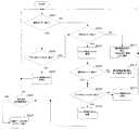
次に、制御手段300による各シャッタ装置200A,200Bの作動の制御について説明する。図22において、制御手段300は、最初に補給樋51にある満杯センサ43からの検出信号の有無により、遊技機島1の上段部分における球の貯留量を判断する(S201)。ここで、満杯センサ43からの検出信号を入力した場合には(S201;YES)、続いて各アウト球回収樋35A,35Bのうち、球が優先的に流下する方のアウト球回収樋35Aにあるアウト球センサ40Aからの検出信号の有無により、貯留部30における球の貯留量を判断する(S202)。  Next, control of the operation of theshutter devices 200A and 200B by the control means 300 will be described. In FIG. 22, the control means 300 first determines the amount of balls stored in the upper part of thegaming machine island 1 based on the presence / absence of a detection signal from thefull sensor 43 in the replenishment basket 51 (S201). Here, when the detection signal from thefull sensor 43 is input (S201; YES), subsequently, out of each of the out-ball collection baskets 35A and 35B, the out-ball collection bowl 35A on which the ball flows down preferentially. Based on the presence or absence of a detection signal from a certain out-ball sensor 40A, the amount of balls stored in thestorage unit 30 is determined (S202).

アウト球センサ40Aからの検出信号の入力がない場合には(S202;NO)、制御手段300は、アウト球センサ40Aの終端側にあるシャッタ装置200Aの作動を停止させて、シャッタ装置200Aにより通路39Aを閉じ(S203)、最初の処理に戻る。このように、既に遊技機島1の上段部分に十分な量の遊技球があり、貯留部30内のアウト球回収樋35Aに球がさほど貯留されていないような場合には、揚送研磨装置100への不必要な球の供給を停止することができる。  When the detection signal is not input from theout ball sensor 40A (S202; NO), thecontrol unit 300 stops the operation of theshutter device 200A on the terminal side of theout ball sensor 40A, and theshutter device 200A passes the passage. 39A is closed (S203), and the process returns to the first process. Thus, when there is already a sufficient amount of game balls in the upper part of thegaming machine island 1 and the balls are not so much stored in the out-ball collecting basket 35A in thestorage unit 30, the lift polishing apparatus The supply of unnecessary spheres to 100 can be stopped.

また、前記満杯センサ43からの検出信号の入力がない場合(S201;NO)や、前記アウト球センサ40Aからの検出信号の入力があった場合(S202;YES)には、今度は揚送研磨装置100にある残球センサ41からの検出信号の有無により、揚送研磨装置100において揚送すべき球の有無を判断する(S206)。  Further, when no detection signal is input from the full sensor 43 (S201; NO), or when a detection signal is input from the out-ball sensor 40A (S202; YES), this time, lift polishing is performed. The presence / absence of a detection signal from the remainingball sensor 41 in theapparatus 100 determines whether or not there is a ball to be lifted in the lifting and polishing apparatus 100 (S206).

残球センサ41からの検出信号の入力がない場合(S206;NO)、制御手段300は揚送研磨装置100の駆動を停止させると共に、揚送研磨装置100に遊技球が供給されていない事態を、表示部310によるエラー表示によって遊技場の関係者に警告して(S211)、最初の処理に戻る。また表示部310と共に、あるいは表示部310に代えて、ホールコンピュータ側の表示部により前記エラー表示による警告をしたり、さらに印刷ないし音声により警告しても良い。  When there is no detection signal input from the remaining ball sensor 41 (S206; NO), the control means 300 stops the driving and polishingapparatus 100, and the game ball is not supplied to the lifting and polishingapparatus 100. Then, the error is displayed on thedisplay unit 310 to warn the people in the game hall (S211), and the process returns to the first process. In addition to thedisplay unit 310 or in place of thedisplay unit 310, a warning by the error display may be given by a display unit on the hall computer side, or a warning may be given by printing or voice.

残球センサ41からの検出信号の入力があった場合(S206;YES)、制御手段300はシャッタ装置200Aを駆動させる(S207)。すなわち、図19において、ロータリーソレノイド202が駆動し、それに伴ないシャッタ201が保持ブラケット204内を下降する。それにより通路39Aが開いて、アウト球回収樋35Aを流下してきた球が揚送研磨装置100に導入される。続いて、揚送パイプ170にある揚送球センサ42からの検出信号の有無により、揚送研磨装置100の駆動に伴ない実際に問題なく遊技球が揚送されているか否かを判断する(S208)。  When a detection signal is input from the remaining ball sensor 41 (S206; YES), thecontrol unit 300 drives theshutter device 200A (S207). That is, in FIG. 19, therotary solenoid 202 is driven, and theshutter 201 is lowered in the holdingbracket 204 as a result. As a result, thepassage 39 </ b> A is opened, and the balls that have flowed down the out-ball collecting bowl 35 </ b> A are introduced into the lifting and polishingapparatus 100. Subsequently, based on the presence or absence of a detection signal from thelift ball sensor 42 in thelift pipe 170, it is determined whether or not the game ball is actually lifted without any problem as thelift polishing apparatus 100 is driven (S208). ).

揚送球センサ42からの検出信号の入力がない場合には(S208;NO)、制御手段300は揚送研磨装置100の駆動を停止させると共に、揚送研磨装置100が駆動しても遊技球が揚送されていない事態を、表示部310により電動モータ130の故障等の異常を遊技場の関係者に警告して(S212)、この時点で一旦処理を終了させる。  When there is no detection signal input from the lifted ball sensor 42 (S208; NO), the control means 300 stops driving the lifted polishingapparatus 100, and the game ball is not driven even if the lifted polishingapparatus 100 is driven. Thedisplay unit 310 warns the abnormality of theelectric motor 130 such as a failure of theelectric motor 130 to the person concerned at the game hall (S212), and terminates the process once at this time.

揚送研磨装置100の電動モータ130の異常に関する警告は、表示部310と共に、あるいは表示部310に代えて、ホールコンピュータ側の表示部により警告したり、さらに印刷ないし音声により警告しても良い。揚送球センサ42からの検出信号の入力があった場合(S208;YES)、揚送研磨装置100は正常に駆動していると判断される。  The warning regarding the abnormality of theelectric motor 130 of the lifting and polishingapparatus 100 may be warned by a display unit on the hall computer side together with thedisplay unit 310 or in place of thedisplay unit 310, or by printing or voice. When a detection signal is input from the lifted ball sensor 42 (S208; YES), it is determined that thelift polishing apparatus 100 is operating normally.

続いて制御手段300は、揚送研磨装置100において今まで揚送された遊技球の数を検出する(S204)。ここで検出されたカウント値が、揚送研磨装置100における研磨テープ150の交換時期として予め定められた所定数(例えば400万個)に達した時には(S204;YES)、研磨テープ150が消耗した旨を表示部310によるアラーム表示によって遊技場の関係者に報知する(S205)。また表示部310と共に、あるいは表示部310に代えて、ホールコンピュータ側の表示部により報知したり、さらに印刷ないし音声により報知しても良い。  Subsequently, the control means 300 detects the number of game balls that have been lifted so far in the lift polishing apparatus 100 (S204). When the detected count value reaches a predetermined number (for example, 4 million pieces) determined in advance as the replacement time of the polishingtape 150 in the lift polishing apparatus 100 (S204; YES), the polishingtape 150 is consumed. A notice to the effect is given to the people in the game hall by an alarm display on the display unit 310 (S205). Further, it may be notified together with thedisplay unit 310 or instead of thedisplay unit 310 by a display unit on the hall computer side, or may be notified by printing or voice.

次に制御手段300は、前記揚送された遊技球の数の検出に関する処理とは別に、前記各アウト球回収樋35A,35Bのうち、もう一方のアウト球回収樋35Bにあるアウト球センサ40Bからの検出信号の有無により、貯留部30における球の貯留量を判断する(S209)。  Next, the control means 300, apart from the processing relating to the detection of the number of lifted game balls, outball sensor 40B in the other outball collection basket 35B out of each of the outball collection baskets 35A, 35B. The amount of stored spheres in thestorage unit 30 is determined based on the presence or absence of a detection signal from (S209).

ここでアウト球センサ40Bからの検出信号の入力がない場合には(S209;NO)、制御手段300は、アウト球センサ40Bの終端側にあるシャッタ装置200Bの作動を停止させて、シャッタ201により通路39Bを閉じて(S213)、最初の処理に戻る。それにより、前記シャッタ装置200Aの作動(駆動)だけで十分な量の遊技球を揚送研磨装置100へ供給できたり、既に遊技機島1の上段部分に十分な量の遊技球があるような場合には、アウト球回収樋35Bからの不必要な球の供給を防止することができる。  Here, when the detection signal is not input from theout ball sensor 40B (S209; NO), thecontrol unit 300 stops the operation of theshutter device 200B on the terminal side of theout ball sensor 40B, and theshutter 201 performs the operation. Thepassage 39B is closed (S213), and the process returns to the first process. Thereby, a sufficient amount of game balls can be supplied to thelift polishing apparatus 100 only by operating (driving) theshutter device 200A, or there is already a sufficient amount of game balls in the upper part of thegaming machine island 1. In this case, unnecessary supply of spheres from the outsphere collection basket 35B can be prevented.

一方、前記アウト球センサ40Bからの検出信号の入力があった場合(S209;YES)、制御手段300は、アウト球センサ40Bの終端側にあるシャッタ装置200Bを駆動させる(S210)。それにより、シャッタ201は下降して通路39Bが開き、アウト球回収樋35Bを流下してきた球が揚送研磨装置100に導入される。  On the other hand, when the detection signal is input from theout ball sensor 40B (S209; YES), the control means 300 drives theshutter device 200B on the terminal side of theout ball sensor 40B (S210). As a result, theshutter 201 is lowered to open thepassage 39B, and the sphere that has flowed down the out-ball collecting rod 35B is introduced into the lifting and polishingapparatus 100.

続いて制御手段300は、再び前述したように、揚送研磨装置100において今まで揚送された遊技球の数を検出することになる(S204)。なお、図22のフローチャートでは省略したが、ステップS210の処理に続いて、さらに揚送パイプ170にある揚送球センサ42からの検出信号の有無により、揚送研磨装置100の駆動に伴ない実際に問題なく遊技球が揚送されているか否かを判断するように設定しても良い。  Subsequently, as described above, the control means 300 detects the number of game balls that have been lifted up to now in the lift polishing apparatus 100 (S204). Although omitted in the flowchart of FIG. 22, following the process of step S <b> 210, the presence or absence of a detection signal from the liftingball sensor 42 in the liftingpipe 170 actually causes the driving and polishingapparatus 100 to be driven. You may set so that it may be judged whether the game ball is lifted without a problem.

このように、本実施の形態によれば、前記制御手段300は、貯留部30における遊技球の貯留量に応じて(S202,S209)、各シャッタ装置200A,200Bの駆動を制御することにより(S203,S207,S210,S213)、貯留部30内の遊技球を遊技機10側へ適量供給することができる。  Thus, according to the present embodiment, the control means 300 controls the driving of theshutter devices 200A and 200B according to the amount of game balls stored in the storage unit 30 (S202, S209) ( S203, S207, S210, S213), an appropriate amount of gaming balls in thestorage unit 30 can be supplied to thegaming machine 10 side.

それにより、揚送研磨装置100は1つだけ設けることにして設備コストを低減した上で、この揚送研磨装置100に対する遊技球の供給量を適正値になるよう正確に調整することができる。なお、揚送研磨装置100は、遊技機10の稼働中は継続して駆動させても良く、あるいは残球センサ41からの検出信号に基づき駆動させるようにしても良い。  Thereby, only onelift polishing apparatus 100 can be provided to reduce the equipment cost, and the amount of game balls supplied to thelift polishing apparatus 100 can be accurately adjusted to an appropriate value. Thelift polishing apparatus 100 may be continuously driven while thegaming machine 10 is operating, or may be driven based on a detection signal from the remainingball sensor 41.

以上、本発明の実施の形態を図面によって説明してきたが、具体的な構成はこれらの実施の形態に限られるものではなく、本発明の要旨を逸脱しない範囲における変更や追加があっても本発明に含まれる。例えば、前記各実施の形態では遊技機10をパチンコ機に適用した場合について説明したが、遊技機10はパチンコ機に限られず、プログラム制御されるスマートボールゲーム機、アレンジボールゲーム機といった他の遊技機であっても良い。  As described above, the embodiments of the present invention have been described with reference to the drawings. However, the specific configuration is not limited to these embodiments, and the present invention can be modified or added without departing from the scope of the present invention. Included in the invention. For example, although the case where thegaming machine 10 is applied to a pachinko machine has been described in each of the above embodiments, thegaming machine 10 is not limited to a pachinko machine, and other games such as a smart ball game machine and an arrangement ball game machine that are program-controlled. It may be a machine.

また、前記遊技機10は遊技媒体が遊技球であるものに限られず、メダルやコインを遊技媒体とするスロットマシン等を遊技機として採用しても良い。この場合には、前記揚送研磨装置100,100A,100Bは、メダルやコインを研磨ないし揚送する装置として構成される。
また、前記各実施の形態では、遊技機島1を構成する遊技機10の数は4台であるが、遊技機島1を構成する遊技機の数はこれに限られるものではなく、1台の遊技機10から成るいわゆる単体島、あるいは2〜3台の遊技機10から成る小規模な遊技機島としたり、あるいは5台以上の遊技機10を列設して構成しても良い。
Further, thegaming machine 10 is not limited to a game ball that is a game ball, and a slot machine or the like that uses medals or coins as a game medium may be adopted as a gaming machine. In this case, the lifting and polishingapparatus 100, 100A, 100B is configured as an apparatus for polishing or lifting medals and coins.
In each of the above embodiments, the number ofgaming machines 10 constituting thegaming machine island 1 is four. However, the number of gaming machines constituting thegaming machine island 1 is not limited to this, and onegaming machine island 1 is provided. Thegame machine 10 may be a so-called single island, or a small-scale game machine island made up of two to threegame machines 10, or five ormore game machines 10 may be arranged in a row.

また、前記第1実施の形態では、複数の供給手段として2つの揚送研磨装置100A,100Bを備えるが、揚送研磨装置の数は2つに限定されるものではなく、遊技機島全体の規模に応じて3つ以上設置するようにしても良い。同様に前記第2実施の形態におけるシャッタ装置200A,200Bも2つに限定されるものではない。
また、前記各実施の形態における供給手段としての揚送装置は、研磨装置と揚送装置を兼用する揚送研磨装置100,100A,100Bとして構成したが、例えば、揚送装置とは別に遊技球を研磨する研磨装置を遊技機島1の適所に配設してもかまわない。
In the first embodiment, the two polishingpolishing apparatuses 100A and 100B are provided as a plurality of supply means, but the number of the lifting polishing apparatuses is not limited to two. You may make it install 3 or more according to a scale. Similarly, theshutter devices 200A and 200B in the second embodiment are not limited to two.
In addition, the lifting device as the supply means in each of the above embodiments is configured as the lifting and polishingdevice 100, 100A, 100B that doubles as the polishing device and the lifting device. For example, a game ball separate from the lifting device A polishing apparatus may be disposed at an appropriate place on thegaming machine island 1.

また、前記各実施の形態では、揚送装置として図示した揚送研磨装置100,100A,100Bを説明したが、他に例えば、貯留部30の底部に連通接続された下端側から上方に延び上る揚送筒部と、前記揚送筒部の下端側から取り入れた遊技球と研磨材との混合物を、撹拌しながら前記揚送筒部内を揚送する螺旋体と、前記揚送筒部の上端側から排出された前記混合物を、球と研磨材とに分離しつつ、球を前記払出口側へ供給する一方、研磨材を再び前記揚送筒部の下端側に循環させる分離供給部とを有した構成としても良い。また、上下方向に延びる一対の研磨ベルトによって、遊技球を研磨揚送しながら揚送する構成でも良い。  In each of the above-described embodiments, the lifting and polishingapparatuses 100, 100A, and 100B illustrated as the lifting apparatus have been described. However, for example, the lifting and polishingapparatuses 100, 100A, and 100B extend upward from the lower end side that is connected to the bottom of thestorage unit 30. A lifting cylinder, a spiral body that lifts the inside of the lifting cylinder while stirring a mixture of a game ball and an abrasive taken from the lower end of the lifting cylinder, and an upper end of the lifting cylinder A separation supply unit for supplying the sphere to the discharge outlet side while separating the mixture discharged from the sphere and the abrasive material, and circulating the abrasive material again to the lower end side of the lifting cylinder unit. It is good also as the structure which did. Further, the game ball may be lifted and lifted by a pair of polishing belts extending vertically.

また、前記各実施の形態では、研磨手段を収納ケース151に収納したカセット状の研磨テープ150としたが、他に例えば、揚送パイプ170の途中に着脱自在に介装される筒状体の内壁に、遊技球に接触して汚れを吸着する研磨材を取り付けて構成したものとしても良い。ここで研磨材は、例えば、6ナイロンまたは66ナイロンを主成分とし、他に静電気除去材や研磨増強材を混入して成形したり、あるいは他の合成樹脂、繊維物質等により成形されるものである。  In each of the above embodiments, the polishing means is the cassette-like polishing tape 150 stored in thestorage case 151. However, for example, a cylindrical body that is detachably interposed in the middle of thefeeding pipe 170 is used. It is good also as what comprised the abrasives which contact a game ball and adsorb | suck dirt on an inner wall. Here, the abrasive is made of, for example, 6 nylon or 66 nylon as a main component, and is molded by mixing with a static eliminating material or a polishing enhancing material, or is molded by other synthetic resin, fiber material, or the like. is there.

また、前記各実施の形態では、制御手段300は、貯留部30における遊技球の貯留量に応じて、各揚送研磨装置100A,100B等の駆動のON/OFFを択一的に選択して制御するように設定したが、制御手段300による各揚送研磨装置100A,100B等の駆動の制御は、単にON/OFFの択一的な選択のみに限定されるわけではなく、駆動の速度やタイミング、それに駆動時間も適宜調整できるように設定しても良い。各シャッタ装置200A,200Bの駆動の制御についても同様であり、開いている時間や開く幅等についても適宜調整できるように設定しても良い。  Further, in each of the above embodiments, the control means 300 selectively selects ON / OFF of driving of each of the lifting and polishingapparatuses 100A, 100B, etc. according to the amount of game balls stored in thestorage unit 30. Although it is set to be controlled, the control of the driving of each of the lifting and polishingapparatuses 100A, 100B, etc. by the control means 300 is not limited to only the selection of ON / OFF. You may set so that timing and drive time can also be adjusted suitably. The same applies to the drive control of theshutter devices 200A and 200B, and the opening time, the opening width, and the like may be set so as to be appropriately adjusted.

また、前記アウト球回収樋35A,35Bにおけるアウト球センサ40A,40Bの具体的な配置位置に関しては、図1および図3で図示した位置に限定されるものではなく、アウト球回収樋35A,35Bの配置を、アウト球センサ40A,40Bの長手方向に沿って変更することにより、検出すべき貯留部30における遊技球の貯留量を調整することが可能となる。  Further, the specific arrangement positions of theout ball sensors 40A and 40B in the outball collection baskets 35A and 35B are not limited to the positions illustrated in FIGS. 1 and 3, and the outball collection baskets 35A and 35B are not limited thereto. Is changed along the longitudinal direction of the out-ball sensors 40A and 40B, it becomes possible to adjust the amount of game balls stored in thestorage unit 30 to be detected.

さらにまた、前記各実施の形態では、報知手段や警告手段を、制御手段300に直接接続された表示部310として説明したが、報知手段や警告手段は表示部310に限られるものではなく、他に例えば、印刷出力装置としてのプリンタ、音声出力装置としてのスピーカやインカム等により構成しても良い。もちろん、報知手段と警告手段とを互いに異なる装置で実現しても良く、また、前述したように制御手段300に直接接続されたものに限らず、ホールコンピュータの周辺機器として構成してもかまわない。  Furthermore, in each of the above-described embodiments, the notification unit and the warning unit are described as thedisplay unit 310 directly connected to thecontrol unit 300. However, the notification unit and the warning unit are not limited to thedisplay unit 310. For example, a printer as a print output device and a speaker or an income as an audio output device may be used. Of course, the notification means and the warning means may be realized by different devices, and are not limited to those directly connected to the control means 300 as described above, and may be configured as peripheral devices of the hall computer. .

2〜3台の遊技機10から成る小規模な遊技機島1に適用したり、あるいは5台以上の遊技機10を列設して構成した遊技機島1に適用することができる。  The present invention can be applied to a small-scalegaming machine island 1 composed of two to threegaming machines 10 or to agaming machine island 1 configured by arranging five ormore gaming machines 10 in a row.

1…遊技機島
2…島枠
3…景品球計数機
10…遊技機
11…遊技機本体
12…ガラス枠
13…遊技盤
14…上受け皿
15…下受け皿
16…ハンドル
17…可変表示装置
18…始動口
19…大入賞口
20…カードユニット
21…カード挿入口
22…度数表示部
23…貸出ボタン
24…返却ボタン
30…貯留部
31…アウト球誘導樋
32…共有樋
33…アウト球通路
34…分配通路
35A…アウト球回収樋
35B…アウト球回収樋
36…貯留球樋
37…異物除去部
38…整列板
39…合流樋
39A…通路
39B…通路
39C…通路
40A…アウト球センサ
40B…アウト球センサ
41…残球センサ
41A…残球センサ
41B…残球センサ
42…揚送球センサ
42A…揚送球センサ
42B…揚送球センサ
43…満杯センサ
50…上部タンク
51…補給樋
52…オーバーフローホース
53…ホッパ
54…シュート
55…ジャバラ
100…揚送研磨装置
100A…揚送研磨装置
100B…揚送研磨装置
101…揚送装置本体
102…ハウジング
110…駆動用歯車
111…嵌合部
112…リブ
113…キャップ
114…案内歯
115…係止歯
116…係止歯
120…筒体
121…上部筒体
122…下部筒体
123…研磨用窓
124…螺旋状凸部
125…連絡用通路
126…空検出手段
130…電動モータ
131…ギアヘッド
132…平歯車
133…軸受
134…回転軸
137…タイミングベルト
140…連動機構
141〜143…シャフト
144…支持ブラケット
146…テープローラ
150…研磨テープ
160…逆流防止機構
170…揚送パイプ
200A…シャッタ装置
200B…シャッタ装置
201…シャッタ
201a…遊び溝
202…ロータリーソレノイド
203…回転板
203a…ピン部
204…保持ブラケット
204a…ガイド溝
300…制御手段
310…表示部
DESCRIPTION OFSYMBOLS 1 ...Game machine island 2 ... Island frame 3 ... Premium ball counter 10 ...Game machine 11 ... Game machinemain body 12 ...Glass frame 13 ...Game board 14 ...Upper tray 15 ...Lower tray 16 ... Handle 17 ...Variable display device 18 ... Startport 19 ... Large winningport 20 ...Card unit 21 ...Card insertion port 22 ...Frequency display unit 23 ...Lending button 24 ...Return button 30 ... Reservingunit 31 ... Out ball guiderod 32 ... Sharedball 33 ... Outball passage 34 ...Distribution passage 35A ... Outball collection bowl 35B ... Outball collection bowl 36 ...Storage ball bowl 37 ... Foreignmatter removal part 38 ...Alignment plate 39 ...Junction bowl 39A ...Path 39B ...Path 39C ...Path 40A ... Outball sensor 40B ... Outball Sensor 41 ...Residual ball sensor 41A ...Residual ball sensor 41B ...Residual ball sensor 42 ... Liftingball sensor 42A ... Liftingball sensor 42B ... Liftingball sensor 43 ...Full sensor 50 ...Upper tank 51 ...Supply tank 52 ...Overflow hose 53 ...Hopper 54 ...Chute 55 ...Bellows 100 ... Lifting polishingapparatus 100A ... Lifting polishingapparatus 100B ... Lifting polishingapparatus 101 ... Lifting apparatusmain body 102 ...Housing 110 ...Drive gear 111 ...Fitting part 112 ...Rib 113 ...Cap 114 ...Guide tooth 115 ... Lockingtooth 116 ... Lockingtooth 120 ...Cylinder 121 ...Upper cylinder 122 ...Lower cylinder 123 ...Polishing window 124 ... Helicalconvex part 125 ... Communication passage 126 ... Empty detection means 130 ...Electric motor 131 ...Gear head 132 ...Spur gear 133 ... Bearing 134 ...Rotating shaft 137 ... Timingbelt 140 ...Interlocking mechanism 141 to 143 ...Shaft 144 ...Support bracket 146 ...Tape roller 150 ...Abrasive tape 160 ...Backflow prevention mechanism 170 Pumpedpipes 200A ...shutter unit 200B ...shutter device 201 ... shutter 201a ... playgrooves 202 ...rotary solenoid 203 ...rotary plate 203a ...pin portion 204 ... holdingbracket 204a ... guidegroove 300 ...control unit 310 ... display unit

Claims (1)

Translated fromJapanese
複数の遊技機と、該遊技機で使用する遊技媒体を貯留する貯留部と、を備えて成る遊技機島において、
前記貯留部内の遊技媒体を互いに独立して研磨しつつ揚送して再び各遊技機へ供給するための複数の揚送研磨装置を備え、
前記貯留部には、遊技機から排出されたアウト遊技媒体を受け入れる誘導樋と、該誘導樋の終端側に設けられた通路部と、前記揚送研磨装置ごとに対応して、前記通路部により分配されたアウト遊技媒体を送る一対の回収樋と、が配置され、
前記一対の回収樋には各々、回収樋内の遊技媒体の貯留量を検出する貯留検出手段が設けられ、
前記揚送研磨装置の本体下部には、揚送すべき遊技球の有無を検出するための検出手段が設けられ、
前記貯留検出手段が前記回収樋内の遊技媒体を検出しているにも関わらず、当該回収樋に対応した前記揚送研磨装置にある前記検出手段が揚送すべき遊技媒体を検出せず遊技媒体が供給されていない場合には、当該回収樋と前記揚送研磨装置との間における不具合が生じたと判断して、当該揚送研磨装置の駆動を停止させることを特徴とする遊技機島。
In a gaming machine island comprising a plurality of gaming machines and a storage unit for storing gaming media used in the gaming machines,
A plurality of lifting and polishing devices for lifting and feeding the game media in the storage unit independently to each other and supplying them to each gaming machine again,
The storage portion includes a guide rod that receives the out game medium discharged from the gaming machine, a passage portion provided on a terminal side of the guide rod, and the passage portion corresponding to each of the lifting and polishing apparatuses. A pair of collection baskets for sending the distributed out game media are arranged,
Each of the pair of collection baskets is provided with storage detection means for detecting the storage amount of the game medium in the collection basket,
A detection means for detecting the presence or absence of a game ball to be lifted is provided at the lower part of the main body of the lift polishing apparatus,
Despite the storing detection means has detected the game media of the recovery in the trough, the game does not detect the game mediumsaid detecting means to be pumpedin the pumped polishing device corresponding to the collection trough If the medium is not supplied, it is determined that a malfunction between the said collecting trough and the pumped polishing apparatus has occurred, the gaming machine islands, characterized inthat make stops driving of the pumped polishing apparatus.
JP2009041738A2009-02-252009-02-25 Amusement machine islandExpired - Fee RelatedJP5312980B2 (en)

Priority Applications (1)

Application NumberPriority DateFiling DateTitle
JP2009041738AJP5312980B2 (en)2009-02-252009-02-25 Amusement machine island

Applications Claiming Priority (1)

Application NumberPriority DateFiling DateTitle
JP2009041738AJP5312980B2 (en)2009-02-252009-02-25 Amusement machine island

Related Parent Applications (1)

Application NumberTitlePriority DateFiling Date
JP2004208226ADivisionJP2006026051A (en)2004-07-152004-07-15Game machine island

Publications (2)

Publication NumberPublication Date
JP2009112843A JP2009112843A (en)2009-05-28
JP5312980B2true JP5312980B2 (en)2013-10-09

Family

ID=40780591

Family Applications (1)

Application NumberTitlePriority DateFiling Date
JP2009041738AExpired - Fee RelatedJP5312980B2 (en)2009-02-252009-02-25 Amusement machine island

Country Status (1)

CountryLink
JP (1)JP5312980B2 (en)

Families Citing this family (1)

* Cited by examiner, † Cited by third party
Publication numberPriority datePublication dateAssigneeTitle
JP2012110561A (en)*2010-11-262012-06-14Ebis Work:KkGame island

Family Cites Families (10)

* Cited by examiner, † Cited by third party
Publication numberPriority datePublication dateAssigneeTitle
JPS527268Y1 (en)*1968-05-151977-02-16
JP3776141B2 (en)*1995-01-232006-05-17株式会社エース電研 Amusement machine island storage tank controller
JPH0938324A (en)*1995-08-011997-02-10Purasuwaaku KkHoisting apparatus for game ball
JPH0938314A (en)*1995-08-041997-02-10Takeya Co LtdBall polishing lift-transporter
JP4075084B2 (en)*1996-10-232008-04-16株式会社竹屋 Pachinko machine management device
JPH10211344A (en)*1997-01-291998-08-11Sankyo KkGame medium circulating system
JP4085454B2 (en)*1998-01-162008-05-14株式会社竹屋 Pachinko island stand
JP4349691B2 (en)*1999-07-062009-10-21株式会社ソフィア Island where game machines are installed
JP2002119744A (en)*2000-10-192002-04-23Heiwa CorpVibration detector for equipment
JP4085960B2 (en)*2003-11-202008-05-14株式会社竹屋 Pachinko island stand

Also Published As

Publication numberPublication date
JP2009112843A (en)2009-05-28

Similar Documents

PublicationPublication DateTitle
JP4340591B2 (en) Collective insertion mechanism of game medals for inter-machines
JP5806962B2 (en) Game ball lifting device
JP2006271550A (en)Ball putting-out device and game machine
JP2006026052A (en)Game machine island
JP5312980B2 (en) Amusement machine island
JPH10216338A (en)Game machine
JP4230183B2 (en) Polishing equipment
JP2005230141A (en)Game medium put-out device
JP2006026051A (en)Game machine island
JP7692589B2 (en) Gaming Machines
JP4628344B2 (en) Game machine
JP2007319430A (en)Game system
JP2005237742A (en)Game medium put-out device
JP4322699B2 (en) Game media payout device
JP5387099B2 (en) Yugi Island System
JP5279593B2 (en) Lifting device
JP2005237743A (en)Game medium put-out device
JP4046199B2 (en) Yugijimadai
JP2005237741A (en)Game parlor managing unit
JP2005237739A (en)Game medium hoisting apparatus
JP2520067B2 (en) Ball supply and reduction system for pachinko game stores
JP2005230145A (en)Game machine island
JP2005230144A (en)Game parlor management device
JP2006334248A (en)Ball put-out device and game machine
JP2005237740A (en)Game medium hoisting device

Legal Events

DateCodeTitleDescription
A621Written request for application examination

Free format text:JAPANESE INTERMEDIATE CODE: A621

Effective date:20090225

A521Request for written amendment filed

Free format text:JAPANESE INTERMEDIATE CODE: A523

Effective date:20090324

A131Notification of reasons for refusal

Free format text:JAPANESE INTERMEDIATE CODE: A131

Effective date:20120117

A521Request for written amendment filed

Free format text:JAPANESE INTERMEDIATE CODE: A523

Effective date:20120306

A02Decision of refusal

Free format text:JAPANESE INTERMEDIATE CODE: A02

Effective date:20120328

A521Request for written amendment filed

Free format text:JAPANESE INTERMEDIATE CODE: A523

Effective date:20120521

A911Transfer to examiner for re-examination before appeal (zenchi)

Free format text:JAPANESE INTERMEDIATE CODE: A911

Effective date:20120528

A912Re-examination (zenchi) completed and case transferred to appeal board

Free format text:JAPANESE INTERMEDIATE CODE: A912

Effective date:20120810

A521Request for written amendment filed

Free format text:JAPANESE INTERMEDIATE CODE: A523

Effective date:20130318

A61First payment of annual fees (during grant procedure)

Free format text:JAPANESE INTERMEDIATE CODE: A61

Effective date:20130703

R150Certificate of patent or registration of utility model

Free format text:JAPANESE INTERMEDIATE CODE: R150

Ref document number:5312980

Country of ref document:JP

Free format text:JAPANESE INTERMEDIATE CODE: R150

R250Receipt of annual fees

Free format text:JAPANESE INTERMEDIATE CODE: R250

R250Receipt of annual fees

Free format text:JAPANESE INTERMEDIATE CODE: R250

R250Receipt of annual fees

Free format text:JAPANESE INTERMEDIATE CODE: R250

R250Receipt of annual fees

Free format text:JAPANESE INTERMEDIATE CODE: R250

R250Receipt of annual fees

Free format text:JAPANESE INTERMEDIATE CODE: R250

R250Receipt of annual fees

Free format text:JAPANESE INTERMEDIATE CODE: R250

R250Receipt of annual fees

Free format text:JAPANESE INTERMEDIATE CODE: R250

R250Receipt of annual fees

Free format text:JAPANESE INTERMEDIATE CODE: R250

LAPSCancellation because of no payment of annual fees

[8]ページ先頭

©2009-2025 Movatter.jp