JP5312571B2 - Elevator equipment - Google Patents
Elevator equipmentDownload PDFInfo
- Publication number
- JP5312571B2 JP5312571B2JP2011502597AJP2011502597AJP5312571B2JP 5312571 B2JP5312571 B2JP 5312571B2JP 2011502597 AJP2011502597 AJP 2011502597AJP 2011502597 AJP2011502597 AJP 2011502597AJP 5312571 B2JP5312571 B2JP 5312571B2
- Authority
- JP
- Japan
- Prior art keywords
- door
- car
- opening
- landing
- inspection
- Prior art date
- Legal status (The legal status is an assumption and is not a legal conclusion. Google has not performed a legal analysis and makes no representation as to the accuracy of the status listed.)
- Active
Links
Images


Classifications
- B—PERFORMING OPERATIONS; TRANSPORTING
- B66—HOISTING; LIFTING; HAULING
- B66B—ELEVATORS; ESCALATORS OR MOVING WALKWAYS
- B66B5/00—Applications of checking, fault-correcting, or safety devices in elevators
- B66B5/0006—Monitoring devices or performance analysers
- B66B5/0018—Devices monitoring the operating condition of the elevator system
- B66B5/0031—Devices monitoring the operating condition of the elevator system for safety reasons
- B—PERFORMING OPERATIONS; TRANSPORTING
- B66—HOISTING; LIFTING; HAULING
- B66B—ELEVATORS; ESCALATORS OR MOVING WALKWAYS
- B66B5/00—Applications of checking, fault-correcting, or safety devices in elevators
- B—PERFORMING OPERATIONS; TRANSPORTING
- B66—HOISTING; LIFTING; HAULING
- B66B—ELEVATORS; ESCALATORS OR MOVING WALKWAYS
- B66B13/00—Doors, gates, or other apparatus controlling access to, or exit from, cages or lift well landings
- B66B13/02—Door or gate operation
- B66B13/14—Control systems or devices
- B—PERFORMING OPERATIONS; TRANSPORTING
- B66—HOISTING; LIFTING; HAULING
- B66B—ELEVATORS; ESCALATORS OR MOVING WALKWAYS
- B66B13/00—Doors, gates, or other apparatus controlling access to, or exit from, cages or lift well landings
- B66B13/22—Operation of door or gate contacts
Landscapes
- Engineering & Computer Science (AREA)
- Automation & Control Theory (AREA)
- Maintenance And Inspection Apparatuses For Elevators (AREA)
- Elevator Door Apparatuses (AREA)
Abstract
Description
Translated fromJapaneseこの発明は、かごの走行時の監視対象の異常状態を検出してかごの走行を阻止する安全監視部を有するエレベータ装置に関するものである。The present invention relatesto elevatorequipment having a safety monitoring section for preventing travel of the car to detect the abnormal state of the monitored during driving of the car.
従来のエレベータ戸開発車防止装置では、戸開状態でかご位置が着床ゾーンを外れると、かご位置補正手段によりかごリレベル動作が実施される。また、戸開時のかご位置と、かご位置補正手段で補正動作を行った後のかご位置との差が予め定めた値を超えると、ロープグリッパにより主索が把持される。これにより、かごがドアゾーンを外れる以前に戸開発車を検出することができ、戸開発車から制動、停止までのかごの走行距離をより短くすることができる(例えば、特許文献1参照)。 In the conventional elevator door development vehicle prevention device, when the car position is out of the landing zone in the door open state, the car re-level operation is performed by the car position correcting means. If the difference between the car position when the door is opened and the car position after the car position correcting means performs the correction operation exceeds a predetermined value, the rope is gripped by the rope gripper. Thereby, the door development vehicle can be detected before the car leaves the door zone, and the traveling distance of the car from the door development vehicle to braking and stopping can be further shortened (see, for example, Patent Document 1).
しかし、従来のエレベータでは、点検時に戸開走行保護装置の正常な動作を確認するには、かごを走行させ、かごがドアゾーン以外を走行している最中に、かご戸又は乗場戸を実際に開く必要があった。そのため、点検を実施する作業者は、かごが走行する位置や速度から、戸を開く間合いを最新の注意を払って判断する必要があり、作業の効率を下げる要因となっていた。 However, with conventional elevators, to check the normal operation of the door-opening travel protection device at the time of inspection, the car is run and the car door or landing door is actually moved while the car is running outside the door zone. I had to open it. For this reason, the worker who carries out the inspection needs to determine the time to open the door with the latest attention from the position and speed at which the car travels, which has been a factor of reducing the efficiency of the work.
この発明は、上記のような課題を解決するためになされたものであり、安全監視部の検査を容易に行うことができるエレベータ装置を得ることを目的とする。The present invention has been made to solve the above problems, an object of the present invention to providean elevatorequipment that can be inspected safety monitoring unit easily.
この発明に係るエレベータ装置は、かご、かごの運転を制御する運転制御部、かごの走行時における監視対象の異常状態を検出してかごの走行を阻止する安全監視部、及び安全監視部の機能を検査するための安全監視機能検査部を備え、安全監視機能検査部は、運転制御部の制御によるかごの走行時に、実際の監視対象の状態によらず、監視対象が異常状態に移行したと安全監視部に検出させる。
また、この発明に係るエレベータ装置は、かご、乗場戸の開閉を検出する開閉検出手段、開閉検出手段に接続され、乗場戸が開いたままでのかごの走行を検出したときにかごの走行を阻止する戸開走行保護装置、及びかごの走行時に、全ての乗場戸が閉じているにも拘わらず、乗場戸のうちの少なくとも1つが開いたと戸開走行保護装置に検出させる検査用戸開認識手段を備えている。
さらに、この発明に係るエレベータ装置の検査方法は、かご、かごの運転を制御する運転制御部、及びエレベータドアが開いているときのかごの走行を阻止する戸開走行保護装置を備えているエレベータ装置の検査方法であって、運転制御部の制御によるかごの走行時に、全てのエレベータドアが閉じた状態のまま、安全監視機能検査部により、エレベータドアのうちの少なくとも1つが開いたと戸開走行保護装置に検出させる。The elevator apparatus according to the present invention has a function of a car, an operation control unit that controls the operation of the car, a safety monitoring unit that detects an abnormal state of a monitoring target during traveling of the car and prevents the traveling of the car, and a safety monitoring unit A safety monitoring function inspection unit is provided for inspecting the vehicle, and the safety monitoring function inspection unit determines that the monitoring target has shifted to an abnormal state when the car is running under the control of the operation control unit, regardless of the actual monitoring target state. Let the safety monitoring department detect it.
The elevator apparatus according to the present invention is connected to the car, the opening / closing detection means for detecting opening / closing of the landing door, and the opening / closing detection means, and prevents the car from traveling when the traveling of the car is detected with the landing door open. And a door open recognition means for detecting that the door open travel protection device detects that at least one of the landing doors is open even though all the landing doors are closed when the car is running. It has.
Furthermore, an inspection method for an elevator apparatus according to the present invention includes an elevator equipped with a car, an operation control unit that controls the operation of the car, and a door opening travel protection device that prevents the car from traveling when the elevator door is open. A method for inspecting a device, wherein when the car is run under the control of the operation control unit, all the elevator doors remain closed and at least one of the elevator doors is opened by the safety monitoring function inspection unit. Let the protection device detect it.
この発明のエレベータ装置は、安全監視機能検査部が、運転制御部の制御によるかごの走行時に、監視対象の実際の状態によらず、監視対象が異常状態に移行したと安全監視部に検出させるので、かごを走行させながら監視対象を実際に異常状態に移行させる必要がなく、安全監視部の検査を容易に行うことができる。
また、この発明のエレベータ装置は、検査用戸開認識手段が、かごの走行時に、全ての乗場戸が閉じているにも拘わらず、乗場戸のうちの少なくとも1つが開いたと戸開走行保護装置に検出させるので、かごを走行させながら、監視対象である乗場戸を実際に開く必要がなく、安全監視部の検査を容易に行うことができる。
さらに、この発明のエレベータ装置の検査方法は、運転制御部の制御によるかごの走行時に、全てのエレベータドアが閉じた状態のまま、安全監視機能検査部により、エレベータドアのうちの少なくとも1つが開いたと戸開走行保護装置に検出させるので、かごを走行させながら、監視対象である乗場戸を実際に開く必要がなく、安全監視部の検査を容易に行うことができる。In the elevator apparatus of the present invention, the safety monitoring function inspection unit causes the safety monitoring unit to detect that the monitoring target has shifted to an abnormal state regardless of the actual state of the monitoring target when the car is running under the control of the operation control unit. Therefore, it is not necessary to actually shift the monitoring target to the abnormal state while the car is running, and the inspection of the safety monitoring unit can be easily performed.
In addition, the elevator device according to the present invention provides a door open travel protection device when the inspection door open recognizing means opens at least one of the landing doors even when all the landing doors are closed when the car is running. Therefore, it is not necessary to actually open the platform door to be monitored while the car is running, and the safety monitoring unit can be easily inspected.
Further, according to the elevator apparatus inspection method of the present invention, when the car is run under the control of the operation control unit, at least one of the elevator doors is opened by the safety monitoring function inspection unit while all the elevator doors are closed. Since the door-opening travel protection device is detected, it is not necessary to actually open the platform door to be monitored while the car is traveling, and the safety monitoring unit can be easily inspected.
以下、この発明を実施するための形態について、図面を参照して説明する。
実施の形態1.
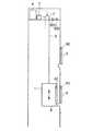
図1はこの発明の実施の形態1によるエレベータ装置を示す概略の構成図である。図1において、かご1及び釣合重り(図示せず)は、懸架手段3により昇降路内に吊り下げられており、巻上機2の駆動力により昇降路内を昇降される。懸架手段3としては、複数本のロープ又は複数本のベルトが用いられている。Hereinafter, embodiments for carrying out the present invention will be described with reference to the drawings.
1 is a schematic configuration diagram showing an elevator apparatus according to
巻上機2は、昇降路の上部に設置されている。また、巻上機2は、懸架手段3が巻き掛けられた駆動シーブと、駆動シーブを回転させる巻上機モータと、駆動シーブの回転を制動する巻上機ブレーキとを有している。 The hoisting
巻上機ブレーキは、駆動シーブと同軸に結合されたブレーキドラムと、ブレーキドラムに接離されるブレーキシューと、ブレーキシューをブレーキドラムに押し付けて制動力を印加するブレーキばねと、ブレーキばねに抗してブレーキシューをブレーキドラムから引き離して制動力を解除する電磁マグネットとを有している。 The hoisting machine brake resists the brake drum, which is coaxially coupled to the drive sheave, the brake shoe that contacts and separates from the brake drum, the brake spring that presses the brake shoe against the brake drum and applies the braking force, and the brake spring. And an electromagnetic magnet for releasing the braking force by pulling the brake shoe away from the brake drum.
巻上機2は、運転制御部としての運転制御装置4により制御される。即ち、かご1の運転は、運転制御装置4により制御される。運転制御装置4は、昇降路の上部で巻上機2の近傍に設置されている。 The hoisting
各停止階の乗場には、乗場出入口を開閉するエレベータドアとしての乗場戸5が設けられている。かご1には、かご出入口を開閉するエレベータドアとしてのかご戸6が設けられている。かご1には、かご戸6を開閉するドア駆動装置が搭載されている。ドア駆動装置は、運転制御装置4により制御される。即ち、かご戸6の開閉は、運転制御装置4により制御される。乗場戸5は、かご戸6に係合することにより、かご戸6に連動して開閉される。 A
各乗場には、乗場戸5の開閉を検出する開閉検出手段としての乗場戸開閉検出装置50が設けられている。かご1には、かご戸6の開閉を検出する開閉検出手段としてのかご戸開閉検出装置60が設けられている。乗場戸5及びかご戸6の開閉は、かご1が乗場階付近の所定の領域、即ちドアゾーン内に存在するときに許可される。 Each landing is provided with a landing door opening /
昇降路の上部には、安全監視部としての戸開走行保護装置7が設けられている。戸開走行保護装置7は、乗場戸5及びかご戸6のうちの少なくとも1つが開いているときにかご1の走行を阻止する。また、戸開走行保護装置7は、かご1がドアゾーン外に存在するときに乗場戸5及びかご戸6の少なくとも1つが開いた場合に、かご1の走行を阻止する。 At the upper part of the hoistway, a door-opening
さらに、戸開走行保護装置7は、上記のような異常状態を検出すると、巻上機モータへの電力供給を遮断するとともに、巻上機ブレーキを制動動作させて、かご1の走行を阻止する。 Further, when the door-opening
戸開走行保護装置7には、戸開走行保護装置7の機能を検査をする安全監視機能検査部としての乗場側検査装置500及びかご側検査装置600が接続されている。 The door-open
図2は図1のエレベータ装置のドアゾーン検出装置を示す構成図である。図2において、かご位置検出手段としてのドアゾーン検出装置80は、昇降路のドアゾーンに対応する位置に設置された複数のドアゾーン検出板81と、かご1に搭載されドアゾーン検出板81によって操作されるドアゾーン検出スイッチ82とを有している。ドアゾーン検出スイッチ82は、かご1がドアゾーン内に存在するときのみドアゾーン検出板81に接する。これにより、かご1がドアゾーン内に存在するかどうかが検出される。 FIG. 2 is a block diagram showing a door zone detection device of the elevator apparatus of FIG. In FIG. 2, a door
図3は図1のエレベータ装置における機器間の電気的な接続状態を示す配線図である。図3において、運転制御装置4は、乗場戸開閉検出装置50、かご戸開閉検出装置60、ドアゾーン検出装置80及び巻上機2に接続されている。これにより、運転制御装置4は、乗場戸5及びかご戸6の開閉状態と、かご1の位置(かご1がドアゾーン内に存在するかどうか)とを検出可能となっている。 FIG. 3 is a wiring diagram showing an electrical connection state between devices in the elevator apparatus of FIG. In FIG. 3, the
また、運転制御装置4は、かご1がドアゾーン内に存在することを確認した上で、乗場戸5及びかご戸6の開閉を行う。さらに、運転制御装置4は、乗場戸5及びかご戸6が完全に閉じられていることを確認した上で、巻上機2を運転してかご1を目的階へ走行させる。 The
戸開走行保護装置7は、乗場側検査装置500を介して乗場戸開閉検出装置50に接続されている。また、戸開走行保護装置7は、かご側検査装置600を介してかご戸開閉検出装置60に接続されている。さらに、戸開走行保護装置7は、ドアゾーン検出装置80及び巻上機2に接続されている。これにより、戸開走行保護装置7は、運転制御装置4から独立して、乗場戸5及びかご戸6の開閉状態と、かご1の位置(かご1がドアゾーン内に存在するかどうか)とを検出可能となっている。 The door-open
戸開走行保護装置7は、かご1がドアゾーン外に存在しているときに、乗場戸5及びかご戸6の少なくともいずれか1つが開いていることを検出すると、巻上機ブレーキを制動動作させる指令を巻上機2に出力する。 When the car
乗場側検査装置500及びかご側検査装置600は、戸開走行保護装置7の機能を検査する際に、検査を実施する作業者により操作される。乗場側検査装置500は、作業者により操作されると、実際の乗場戸5の開閉状態によらず、即ち全ての乗場戸5が閉じていても、乗場戸5のうちの少なくとも1つが開いたと戸開走行保護装置7に検出させる。 The landing
同様に、かご側検査装置600は、作業者により操作されると、実際のかご戸6の開閉状態によらず、即ちかご戸6が閉じていても、かご戸6が開いたと戸開走行保護装置7に検出させる。これにより、かご1を走行させた上で、乗場戸5及びかご戸6を実際に開けずとも、戸開走行保護装置7の機能を確認できる。 Similarly, when the car-
図4は図1の乗場戸開閉検出装置50を示す正面図、図5は図4の乗場戸5の開動作開始直前の状態を示す正面図、図6は図4の乗場戸5の開動作中の状態を示す正面図である。図4〜6において、乗場戸5の上部には、乗場戸5を三方枠8に機械的に連結して乗場戸5が不用意に開くのを防止する乗場戸ロック機構51が設けられている。乗場戸ロック機構51は、乗場戸5が完全に閉じられているとき、図4に示すように施錠された状態となり、乗場戸5が開かれるときにのみ、図5及び図6に示すように開錠される。 4 is a front view showing the landing door opening /
三方枠8と乗場戸ロック機構51との間には、ドアスイッチとしての乗場戸インターロックスイッチ52が設けられている。乗場戸インターロックスイッチ52は、乗場戸ロック機構51が施錠されているときにのみ閉となって通電状態となり、乗場戸ロック機構51が開錠されたときには開となり通電を遮断する構成となっている。乗場戸開閉検出装置50は、乗場戸ロック機構51及び乗場戸インターロックスイッチ52を有している。 A landing
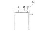
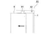
図7は図1のかご戸開閉検出装置60を示す正面図、図8は図7のかご戸6の開動作中の状態を示す正面図である。図7、8において、かご戸6の上部には、かご戸インターロック用接点61が設けられている。かご出入口の上部には、ドアスイッチとしてのかご戸インターロックスイッチ62が設けられている。 7 is a front view showing the car door opening /
図7に示すように、かご戸6が完全に閉じられているときは、かご戸インターロック用接点61がかご戸インターロックスイッチ62に接しており、かご戸インターロックスイッチ62は閉となって通電状態となっている。また、図8に示すように、かご戸6が少しでも開いているときは、かご戸インターロック用接点61がかご戸インターロックスイッチ62の接点から離れ、かご戸インターロックスイッチ62は開となり通電を遮断する構成となっている。かご戸開閉検出装置60は、かご戸インターロック用接点61及びかご戸インターロックスイッチ62を有している。 As shown in FIG. 7, when the
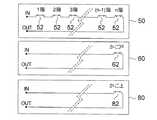
図9は図1の乗場戸開閉検出装置50及びかご戸開閉検出装置60と図2のドアゾーン検出装置80とを示す回路図である。乗場戸開閉検出装置50において、全ての停止階の乗場戸インターロックスイッチ52は、直列に接続されている。そして、乗場戸インターロックスイッチ52のうちの少なくとも1つが開かれると、IN−OUT間の通電が遮断される。 FIG. 9 is a circuit diagram showing the landing door opening /
また、かご戸開閉検出装置60において、かご戸インターロックスイッチ62が開かれると、IN−OUT間の通電が遮断される。さらに、ドアゾーン検出装置80において、ドアゾーン検出スイッチ82が開かれると、IN−OUT間の通電が遮断される。 In the car door opening /
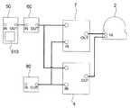
図10は図1の乗場側検査装置500及びかご側検査装置600を示す回路図である。乗場側検査装置500及びかご側検査装置600は、作業者によって操作される検査スイッチ1000によってそれぞれ構成されている。検査スイッチ1000は、通常時は閉となっている。また、作業者の操作によって検査スイッチ1000が開かれると、IN−OUT間の通電が遮断される。 FIG. 10 is a circuit diagram showing the landing
乗場側検査装置500及びかご側検査装置600は、作業者以外の操作によってかご1の走行が停止されるのを防ぐため、機械室や乗場操作盤内などの一般利用者が容易に触れられない位置に設置される。また、検査作業時にのみ乗場側検査装置500及びかご側検査装置600を追加できる構成としてもよい。 The landing-
なお、運転制御装置4及び戸開走行保護装置7は、それぞれマイクロコンピュータを有している。即ち、運転制御装置4及び戸開走行保護装置7の機能は、マイクロコンピュータを用いて実現することができる。
また、戸開走行保護装置7の機能は、アナログ回路によって実現することもできる。Note that each of the
The function of the door-opening
次に、戸開走行保護装置7の機能の検査方法について説明する。まず、作業者は、かご1を所定の階に停止させる。この後、乗場側検査装置500の検査スイッチ1000を開に切り替える。この状態で、かご1を走行させ、戸開走行保護装置7が戸開走行を検出してかご1の走行を阻止することを確認する。そして、乗場側検査装置500の検査スイッチ1000を閉に戻し、かご1を再び所定の階に停止させる。 Next, the function inspection method of the door-opening
次に、かご側検査装置600の検査スイッチ1000を開に切り替える。この状態で、かご1を走行させ、戸開走行保護装置7が戸開走行を検出してかご1の走行を阻止することを確認する。そして、かご側検査装置600の検査スイッチ1000を閉に戻してエレベータ装置を通常の状態に復帰させる。 Next, the
このようなエレベータ装置では、乗場側検査装置500及びかご側検査装置600が、運転制御装置4の制御によるかご1の走行時に、乗場戸5及びかご戸6の実際の状態によらず、乗場戸5及びかご戸6の少なくともいずれか1つが開いたと戸開走行保護装置7に検出させるので、かご1を走行させながら乗場戸5やかご戸6を実際に開く必要がなく、戸開走行保護装置7の検査を容易に効率良く行うことができる。 In such an elevator apparatus, the landing-
また、かご1を走行させている最中に、検査スイッチ1000を開いて戸開走行保護装置7が正常に動作するかどうかを検査することも可能であり、この場合も乗場戸5やかご戸6を実際に開く必要がないので、戸開走行保護装置7の検査を容易に効率良く行うことができる。 In addition, while the
さらに、作業者が操作を誤っても、実際の乗場戸5やかご戸6が開いているときに、戸開走行保護装置7に閉と認識させることはないので、誤操作による戸開走行を防止することができる。 Furthermore, even if the operator makes an operation mistake, when the
実施の形態2.
次に、図11はこの発明の実施の形態2によるエレベータ装置を示す概略の構成図である。図11において、戸開走行保護装置7には、戸開走行保護装置7の機能を検査をする安全監視機能検査部としての機能検査装置900が接続されている。
Next, FIG. 11 is a schematic configuration diagram showing an elevator apparatus according to
図12は図11のエレベータ装置における機器間の電気的な接続状態を示す配線図である。図12において、乗場戸開閉検出装置50とかご戸開閉検出装置60とは直列に接続されている。戸開走行保護装置7は、機能検査装置900を介して乗場戸開閉検出装置50及びかご戸開閉検出装置60に接続されている。 FIG. 12 is a wiring diagram showing an electrical connection state between devices in the elevator apparatus of FIG. In FIG. 12, the landing door opening /
機能検査装置900は、戸開走行保護装置7の機能を検査する際に、検査を実施する作業者により操作される。機能検査装置900は、作業者により操作されると、実際の乗場戸5及びかご戸6の開閉状態によらず、即ち乗場戸5及びかご戸6の全てが閉じていても、乗場戸5及びかご戸6のうちの少なくとも1つが開いたと戸開走行保護装置7に検出させる。 The
機能検査装置900は、図10と同様に、作業者によって操作される検査スイッチ1000によって構成されている。また、機能検査装置900は、作業者以外の操作によってかご1の走行が停止されるのを防ぐため、機械室や乗場操作盤内などの一般利用者が容易に触れられない位置に設置される。また、機能検査装置900を追加できる構成としてもよい。他の構成は、実施の形態1と同様である。 Similar to FIG. 10, the
次に、戸開走行保護装置7の機能の検査方法について説明する。まず、作業者は、かご1を所定の階に停止させる。この後、機能検査装置900の検査スイッチ1000を開に切り替える。この状態で、かご1を走行させ、戸開走行保護装置7が戸開走行を検出してかご1の走行を阻止することを確認する。そして、機能検査装置900の検査スイッチ1000を閉に戻してエレベータ装置を通常の状態に復帰させる。 Next, the function inspection method of the door-opening
このようなエレベータ装置では、機能検査装置900が、運転制御装置4の制御によるかご1の走行時に、乗場戸5及びかご戸6の実際の状態によらず、乗場戸5及びかご戸6の少なくともいずれか1つが開いたと戸開走行保護装置7に検出させるので、かご1を走行させながら乗場戸5やかご戸6を実際に開く必要がなく、戸開走行保護装置7の検査を容易に効率良く行うことができる。 In such an elevator apparatus, the
また、かご1を走行させている最中に、検査スイッチ1000を開いて戸開走行保護装置7が正常に動作するかどうかを検査することも可能であり、この場合も乗場戸5やかご戸6を実際に開く必要がないので、戸開走行保護装置7の検査を容易に効率良く行うことができる。 In addition, while the
さらに、実施の形態1と異なり、乗場戸開閉検出装置50とかご戸開閉検出装置60とが直列に配置されるため、戸開走行保護装置7は、乗場戸5とかご戸6との開閉の区別を付けられないが、いずれか一方が開となったことを検出できる。このため、実施の形態1とは異なり、検査作業用に追加する装置を1つ(機能検査装置900のみ)にすることができ、作業手順を減らすことができる。 Further, unlike the first embodiment, since the landing door opening /
実施の形態3.
次に、図13はこの発明の実施の形態3によるエレベータ装置を示す概略の構成図である。図13において、戸開走行保護装置7には、戸開走行保護装置7の機能を検査をする安全監視機能検査部としての機能検査装置910が接続されている。Embodiment 3 FIG.
Next, FIG. 13 is a schematic configuration diagram showing an elevator apparatus according to Embodiment 3 of the present invention. In FIG. 13, the door opening
図14は図13のエレベータ装置における機器間の電気的な接続状態を示す配線図である。実施の形態2の機能検査装置900は、乗場戸開閉検出装置50及びかご戸開閉検出装置60と戸開走行保護装置7との間に接続されていたが、実施の形態3の機能検査装置910は、乗場戸開閉検出装置50及びかご戸開閉検出装置60とは別に、戸開走行保護装置7に接続されている。 FIG. 14 is a wiring diagram showing an electrical connection state between devices in the elevator apparatus of FIG. The
機能検査装置910は、戸開走行保護装置7の機能を検査する際に、検査を実施する作業者により操作される。機能検査装置910は、作業者により操作されると、実際の乗場戸5及びかご戸6の開閉状態によらず、即ち乗場戸5及びかご戸6の全てが閉じていても、乗場戸5及びかご戸6のうちの少なくとも1つが開いたと戸開走行保護装置7に検出させる。 The
具体的には、実施の形態3の機能検査装置910は、作業者によって操作されると、乗場戸5及びかご戸6のうちの少なくとも1つが開いたことを伝える戸開検出信号を戸開走行保護装置7に対して出力する。戸開走行保護装置7は、機能検査装置910からの戸開検出信号が入力されると、乗場戸5及びかご戸6の少なくとも1つが開いた場合と同様に動作する。 Specifically, the
さらに詳細には、機能検査装置910は、通常時はLow(例えば0ボルト)の信号を出力し、検査を実施する作業者が操作することによってHigh(例えば5ボルト)の信号を出力する。 More specifically, the
戸開走行保護装置7は、機能検査装置910からの信号が通常時であることを示すLow信号であれば、乗場戸開閉検出装置50及びかご戸開閉検出装置60によって得られた情報を基にかご戸開閉状態を検出する。 If the signal from the
また、戸開走行保護装置7は、機能検査装置910からの信号が検査時であることを示すHigh信号であれば、乗場戸開閉検出装置50及びかご戸開閉検出装置60によって得られた情報によらず、いずれかの戸が開いているものと判断する。さらに、戸開走行保護装置7は、機能検査装置910からの信号と乗場戸開閉検出装置50及びかご戸開閉検出装置60の信号とから戸開閉を判断する処理を、例えば電子回路による演算処理によって実現する。他の構成は、実施の形態2と同様である。 Moreover, if the signal from the function test |
次に、戸開走行保護装置7の機能の検査方法について説明する。まず、作業者は、かご1を所定の階に停止させる。この後、機能検査装置910を操作して戸開検出信号を戸開走行保護装置7に入力する。この状態で、かご1を走行させ、戸開走行保護装置7が戸開走行を検出してかご1の走行を阻止することを確認する。そして、機能検査装置910を通常状態に戻してエレベータ装置を通常の状態に復帰させる。 Next, the function inspection method of the door-opening
このようなエレベータ装置では、機能検査装置910が、運転制御装置4の制御によるかご1の走行時に、乗場戸5及びかご戸6の実際の状態によらず、乗場戸5及びかご戸6の少なくともいずれか1つが開いたと戸開走行保護装置7に検出させるので、かご1を走行させながら乗場戸5やかご戸6を実際に開く必要がなく、戸開走行保護装置7の検査を容易に効率良く行うことができる。 In such an elevator apparatus, the
また、かご1を走行させている最中に、機能検査装置910を操作して戸開走行保護装置7が正常に動作するかどうかを検査することも可能であり、この場合も乗場戸5やかご戸6を実際に開く必要がないので、戸開走行保護装置7の検査を容易に効率良く行うことができる。 In addition, while the
実施の形態4.
次に、図15はこの発明の実施の形態4によるエレベータ装置を示す概略の構成図である。図15において、昇降路の上部には、運転制御部及び安全監視部を兼ねる戸開走行保護機能付き制御装置9が設けられている。戸開走行保護機能付き制御装置9は、実施の形態1〜3で示した運転制御装置4及び戸開走行保護装置7を一体化したものであり、これら両方の機能を有している。
Next, FIG. 15 is a schematic configuration diagram showing an elevator apparatus according to
また、戸開走行保護機能付き制御装置9には、その戸開走行保護機能を検査をする安全監視機能検査部としての検査モード切替装置920が接続されている。 In addition, an inspection
図16は図15のエレベータ装置における機器間の電気的な接続状態を示す配線図である。図16において、戸開走行保護機能付き制御装置9は、直列に配列された乗場戸開閉検出装置50及びかご戸開閉検出装置60と、検査モード切替装置920と、ドアゾーン検出装置80と、巻上機2とに接続されている。これにより、戸開走行保護機能付き制御装置9は、乗場戸5及びかご戸6の開閉状態と、かご1の位置(かご1がドアゾーン内に存在するかどうか)とを検出可能となっている。 FIG. 16 is a wiring diagram showing an electrical connection state between devices in the elevator apparatus of FIG. In FIG. 16, the control device 9 with a door-opening travel protection function includes a landing door opening /
また、戸開走行保護機能付き制御装置9は、かご1がドアゾーン内に存在することを確認した上で、乗場戸5及びかご戸6の開閉を行う。さらに、戸開走行保護機能付き制御装置9は、乗場戸5及びかご戸6が完全に閉じられていることを確認した上で、巻上機2を運転してかご1を目的階へ走行させる。 Moreover, the control apparatus 9 with a door open travel protection function opens and closes the
さらにまた、戸開走行保護機能付き制御装置9は、かご1がドアゾーン外に存在しているときに、乗場戸5及びかご戸6の少なくともいずれか1つが開いていることを検出すると、巻上機ブレーキを制動動作させる指令を巻上機2に出力する。 Furthermore, when the control device 9 with the door-opening travel protection function detects that at least one of the
検査モード切替装置920は、戸開走行保護機能を検査する際に、検査を実施する作業者により操作される。検査モード切替装置920は、作業者により操作されると、検査を開始したことを伝える検査開始信号と、乗場戸5及びかご戸6の少なくとも1つの戸開を検出したことを伝える戸開検出信号とを、戸開走行保護機能付き制御装置9に対して出力する。 The inspection
戸開走行保護機能付き制御装置9は、検査モード切替装置920から戸開検出信号を受けると、実際の乗場戸5及びかご戸6の開閉状態によらず、即ち乗場戸5及びかご戸6の全てが閉じていても、乗場戸5及びかご戸6のうちの少なくとも1つが開いたことを検出する。また、戸開走行保護機能付き制御装置9は、検査開始信号を受けると、乗場戸5及びかご戸6の開閉状態によらず、かご1の走行を開始させることが可能となる。 When receiving the door open detection signal from the inspection
さらに詳細には、検査モード切替装置920は、通常時はLow(例えば0ボルト)の信号を出力し、検査を実施する作業者が操作することによってHigh(例えば5ボルト)の信号を出力する。 More specifically, the inspection
戸開走行保護機能付き制御装置9は、検査モード切替装置920からの信号が通常時であることを示すLow信号であれば、乗場戸開閉検出装置50及びかご戸開閉検出装置60によって得られた情報を基にかご戸開閉状態を検出する。 When the signal from the inspection
また、戸開走行保護機能付き制御装置9は、検査モード切替装置920からの信号が検査時であることを示すHigh信号であれば、乗場戸開閉検出装置50及びかご戸開閉検出装置60によって得られた情報によらず、かご1の走行を開始させることができ、また同時に、戸開走行保護機能付き制御装置9はいずれかの戸が開いているものと判断する。 If the signal from the inspection
さらに、戸開走行保護機能付き制御装置9は、検査モード切替装置920からの信号と乗場戸開閉検出装置50及びかご戸開閉検出装置60の信号とから戸開閉を判断する処理を、例えば電子回路による演算処理によって実現する。他の構成は、実施の形態3と同様である。 Further, the control device 9 with a door-opening travel protection function performs a process of determining door opening / closing based on a signal from the inspection
次に、戸開走行保護機能付き制御装置9の戸開走行保護機能の検査方法について説明する。まず、作業者は、かご1を所定の階に停止させる。この後、検査モード切替装置920を操作して検査開始信号及び戸開検出信号を戸開走行保護機能付き制御装置9に入力する。この状態で、かご1の走行を開始させ、戸開走行保護機能付き制御装置9が戸開走行を検出してかご1の走行を阻止することを確認する。そして、検査モード切替装置920を通常状態に戻してエレベータ装置を通常の状態に復帰させる。 Next, the inspection method of the door opening traveling protection function of the control device 9 with the door opening traveling protection function will be described. First, the worker stops the
このようなエレベータ装置では、検査モード切替装置920が、戸開走行保護機能付き制御装置9の制御によるかご1の走行時に、乗場戸5及びかご戸6の実際の状態によらず、乗場戸5及びかご戸6の少なくともいずれか1つが開いたと戸開走行保護機能付き制御装置9に検出させるので、かご1を走行させながら乗場戸5やかご戸6を実際に開く必要がなく、戸開走行保護機能付き制御装置9の戸開走行保護機能の検査を容易に効率良く行うことができる。 In such an elevator apparatus, the inspection
また、かご1を走行させている最中に、検査モード切替装置920を操作して戸開走行保護機能が正常であるかどうかを検査することも可能であり、この場合も乗場戸5やかご戸6を実際に開く必要がないので、戸開走行保護機能の検査を容易に効率良く行うことができる。 In addition, while the
実施の形態5.
次に、図17はこの発明の実施の形態5によるエレベータ装置を示す概略の構成図である。図17において、予め選択された1つの乗場には、戸開走行保護装置7の機能を検査をする安全監視機能検査部及び検査用戸開認識手段としての乗場戸インターロック解除装置510が設けられている。乗場戸インターロック解除装置510は、乗場戸開閉検出装置50を強制的に戸開検出状態に駆動する。
Next, FIG. 17 is a schematic configuration diagram showing an elevator apparatus according to
図18は図17のエレベータ装置における機器間の電気的な接続状態を示す配線図であり、実施の形態2(図12)との相違は、かご戸開閉検出装置60と戸開走行保護装置7との間に機能検査装置900が設けられていない点と、乗場戸開閉検出装置50に乗場戸インターロック解除装置510が設けられている点とである。 FIG. 18 is a wiring diagram showing an electrical connection state between devices in the elevator apparatus of FIG. 17, and the difference from the second embodiment (FIG. 12) is that the car door opening /
乗場戸インターロック解除装置510は、戸開走行保護装置7の機能を検査する際に、検査を実施する作業者により操作される。乗場戸インターロック解除装置510は、作業者により操作されると、実際の乗場戸5の開閉状態によらず、即ち全ての乗場戸5が閉じていても、乗場戸5のうちの1つが開いたと戸開走行保護装置7に検出させる。これにより、かご1を走行させた上で、乗場戸5を実際に開けずとも、戸開走行保護装置7の機能を確認できる。 The landing door
図19は図17の乗場戸インターロック解除装置510を示す正面図、図20は図19の乗場戸インターロック解除装置510の戸開走行保護機能検査時の状態を示す正面図である。乗場戸インターロック解除装置510は、乗場戸ロック機構51に接して回転可能な円板カムを有している。この円板カムを手動又はモータ等の駆動力で回転させることにより、乗場戸ロック機構51が図20のように回動され、乗場戸インターロックスイッチ52が強制的に開にされる。他の構成は、実施の形態2と同様である。 FIG. 19 is a front view showing the landing door
なお、乗場戸インターロック解除装置510の円板カムは、乗場戸ロック機構51を完全には解錠せず、かつ乗場戸インターロックスイッチ52を開とする程度の大きさのものを使用する。これは、乗場戸インターロック解除装置510の操作によって不用意に乗場戸5が開かないようにする措置である。 The disk cam of the landing door
次に、戸開走行保護装置7の機能の検査方法について説明する。まず、作業者は、かご1を走行させる。この後、乗場戸インターロック解除装置510を操作し、乗場戸インターロックスイッチ52を強制的に開にし、戸開走行保護装置7が戸開走行を検出してかご1の走行を阻止することを確認する。そして、乗場戸インターロック解除装置510を元の状態に戻してエレベータ装置を通常の状態に復帰させる。 Next, the function inspection method of the door-opening
このようなエレベータ装置では、乗場戸インターロック解除装置510が、運転制御装置4の制御によるかご1の走行時に、乗場戸5の実際の状態によらず、乗場戸5の1つが開いたと戸開走行保護装置7に検出させるので、かご1を走行させながら乗場戸5やかご戸6を実際に開く必要がなく、戸開走行保護装置7の検査を容易に効率良く行うことができる。 In such an elevator apparatus, when one of the
なお、実施の形態5では、円板カムを用いた乗場戸インターロック解除装置510を示したが、検査用戸開認識手段はこれに限定されるものではなく、例えば、ワイヤ、リンク機構又はボールねじを用いたものであってもよい。また、従来の乗場戸の開錠に用いてきた鍵によって乗場戸ロック機構51を駆動できる構造によっても実現できる。 In the fifth embodiment, the landing door
また、実施の形態1〜5では、ドアゾーン検出スイッチ82をかご1に搭載したが、昇降路側に複数のドアゾーン検出スイッチを設置し、かご1にはドアゾーン検出スイッチを操作する操作片を搭載してもよい。
さらに、ドアゾーン検出装置(かご位置検出手段)は、ドアゾーン検出スイッチ82を機械的に操作するものに限定されず、例えば、光学的なセンサや磁気センサ等を用いるものであってもよい。In the first to fifth embodiments, the door
Furthermore, the door zone detection device (car position detection means) is not limited to one that mechanically operates the door
さらにまた、実施の形態1〜2に記載の検査スイッチ1000、実施の形態3に記載の機能検査装置910、実施の形態4に記載の検査モード切替装置920、実施の形態5に記載の乗場戸インターロック解除装置510は、サービスステーション等の遠隔地からの操作によって動作する構成にしてもよい。これにより、作業者が現場に行かなくても検査を実施することができ、作業者が現場で実施する検査項目を削減することができる。 Furthermore, the
また、実施の形態1〜5では、運転制御装置4、戸開走行保護装置7及び戸開走行保護機能付き制御装置9等が昇降路の上部に設置されているが、これらの設置場所は特に限定されるものではなく、この発明は機械室レスエレベータにも適用できる。 In the first to fifth embodiments, the
さらに、巻上機2の設置場所や台数、ローピング方式、及びかご1の台数等も特に限定されるものではなく、この発明はあらゆるタイプのエレベータ装置に適用できる。 Further, the installation location and the number of
さらにまた、実施の形態1〜5では、安全監視部が検出する異常状態として戸開走行を示したが、監視対象はエレベータドアに限定されるものではなく、異常状態も戸開走行に限定されるものではない。
戸開走行以外の異常状態としては、例えば、過速度走行や終端階行き過ぎ運転等を挙げることができる。
これらのうち、過速度走行の有無を監視する安全監視部の検査を行う場合、安全監視機能検査部は、例えば過速度走行を判断する基準の速度を通常よりも低く設定することで、正常な速度で走行していても安全監視部が異常を検出した状態を模擬する。
また、終端階行き過ぎ運転の有無を監視する安全監視部の検査を行う場合、安全監視機能検査部は、例えばかごが終端階を行き過ぎたときにかごにより操作される終端階行き過検出スイッチを遠隔操作することによって、かごが終端階行き過検出スイッチに接触することなく、終端階行き過ぎを検出する状態を模擬する。Furthermore, in
As an abnormal state other than the door-opening traveling, for example, overspeed traveling, overrunning operation on the final floor, and the like can be cited.
Among these, when performing the inspection of the safety monitoring unit that monitors the presence or absence of overspeed traveling, the safety monitoring function inspection unit is normal by setting a reference speed for determining overspeed traveling lower than normal, for example. Simulates the state in which the safety monitoring unit detects an abnormality even when traveling at speed.
In addition, when performing inspection of the safety monitoring unit that monitors the presence / absence of overrun operation on the terminal floor, the safety monitoring function inspection unit remotely connects the terminal floor overload detection switch operated by the car when the car goes over the terminal floor, for example. By operating, a state in which the car detects overshoot at the terminal floor without touching the terminal floor excess detection switch is simulated.
Claims (3)
Translated fromJapanese前記かごの走行時における監視対象の異常状態を検出して前記かごの走行を阻止する安全監視部、及び
前記安全監視部の機能を検査するための安全監視機能検査部
を備え、
前記監視対象はエレベータドアであり、
前記エレベータドアが開いているときに開となり、前記エレベータドアが閉じているときに閉となるドアスイッチをさらに備え、
前記安全監視部は、前記ドアスイッチに接続されており、
前記安全監視部は、前記ドアスイッチが開くことにより前記安全監視部への信号の入力が遮断されたときに異常であることを検出し、
前記安全監視機能検査部は、前記ドアスイッチと前記安全監視部との間に設けられた通常時は閉となる検査スイッチを有しており、
前記検査スイッチが開かれることによって、前記エレベータドアの状態によらず、前記ドアスイッチから前記安全監視部への信号が遮断されることを特徴とするエレベータ装置。Basket,
Safety monitoring section detects an abnormal state of the monitored during runningprior Symbol cage prevents the running of the car, and with a safety monitoring checking unit for checking the functionality of the safety monitoring unit,
The monitoring object is an elevator door,
A door switch that opens when the elevator door is open and closes when the elevator door is closed;
The safety monitoring unit is connected to the door switch,
The safety monitoring unit detects an abnormality when an input of a signal to the safety monitoring unit is blocked by opening the door switch,
The safety monitoring function inspection unit has an inspection switch that is normally closed between the door switch and the safety monitoring unit,
An elevator apparatus characterized inthat, when the inspection switch is opened, a signal from the door switch to the safety monitoring unit is interrupted regardless of a state of the elevator door .
をさらに備え、
前記安全監視部は、前記かご位置検出手段に接続されており、前記かごが前記ドアゾーン外に存在するときに前記ドアスイッチと前記安全監視部との間の通電が遮断された場合に異常であることを検出することを特徴とする請求項1記載のエレベータ装置。Before Symbol further comprising a car position detection means or the car in the door zone to allow the opening of the elevator door to detect whether there is,
Said safety monitoring unitis connectedbefore Symbol car position detecting handstage,abnormal whenthe current between the door switch and the safety monitoring unit is interrupted when the car is outside the door zone elevator apparatus according to claim1, whereindetecting that at.
乗場戸の開閉を検出する開閉検出手段、
前記開閉検出手段に接続され、前記乗場戸が開いたままでの前記かごの走行を検出したときに前記かごの走行を阻止する戸開走行保護装置、及び
前記かごの走行時に、全ての前記乗場戸が閉じているにも拘わらず、前記乗場戸のうちの少なくとも1つが開いたと前記戸開走行保護装置に検出させる検査用戸開認識手段
を備え、
前記開閉検出手段は、前記乗場戸が開いているときに開となり、前記乗場戸が閉じているときに閉となるドアスイッチを有しており、
前記戸開走行保護装置は、前記ドアスイッチに接続されており、
前記検査用戸開認識手段は、操作されることにより、前記乗場戸が閉じているにも拘わらず、前記ドアスイッチを開くことを特徴とするエレベータ装置。Basket,
Open / close detection means for detecting opening / closing of a landing door,
A door-opening travel protection device that is connected to the open / close detection means and prevents travel of the car when the travel of the car is detected while the landing door is open; and all the landing doors when the car travels A door opening recognition means for inspection that causes the door opening travel protection device to detect that at least one of the landing doors is opened despite being closed,
The open / close detection means has a door switch that is open when the landing door is open and closed when the landing door is closed,
The door opening travel protection device is connected to the door switch,
The inspection device opening recognition means is operated to open the door switch even when the landing door is closed .
Priority Applications (1)
| Application Number | Priority Date | Filing Date | Title |
|---|---|---|---|
| JP2011502597AJP5312571B2 (en) | 2009-03-04 | 2009-12-15 | Elevator equipment |
Applications Claiming Priority (4)
| Application Number | Priority Date | Filing Date | Title |
|---|---|---|---|
| JP2009050510 | 2009-03-04 | ||
| JP2009050510 | 2009-03-04 | ||
| PCT/JP2009/070896WO2010100802A1 (en) | 2009-03-04 | 2009-12-15 | Elevator device and method of inspecting same |
| JP2011502597AJP5312571B2 (en) | 2009-03-04 | 2009-12-15 | Elevator equipment |
Publications (2)
| Publication Number | Publication Date |
|---|---|
| JPWO2010100802A1 JPWO2010100802A1 (en) | 2012-09-06 |
| JP5312571B2true JP5312571B2 (en) | 2013-10-09 |
Family
ID=42709376
Family Applications (1)
| Application Number | Title | Priority Date | Filing Date |
|---|---|---|---|
| JP2011502597AActiveJP5312571B2 (en) | 2009-03-04 | 2009-12-15 | Elevator equipment |
Country Status (6)
| Country | Link |
|---|---|
| US (1) | US8807285B2 (en) |
| JP (1) | JP5312571B2 (en) |
| KR (1) | KR101331390B1 (en) |
| CN (1) | CN102317192B (en) |
| DE (1) | DE112009004592B4 (en) |
| WO (1) | WO2010100802A1 (en) |
Families Citing this family (20)
| Publication number | Priority date | Publication date | Assignee | Title |
|---|---|---|---|---|
| JPWO2010150341A1 (en)* | 2009-06-22 | 2012-12-06 | 三菱電機株式会社 | Elevator equipment |
| DE102012005541A1 (en)* | 2012-03-21 | 2013-09-26 | Aufzugswerke M. Schmitt & Sohn Gmbh & Co. | Shaft safety device for protecting maintenance worker of lift system, has safety circuit that is stopped, when position sensor detects that lift cabin is not positioned in specific region of shaft door |
| TWI622548B (en)* | 2012-12-13 | 2018-05-01 | 伊文修股份有限公司 | Monitoring device for a transport installation for persons, trasnport installation for persons, and method of monitoring a transport installation for persons |
| ES2483816B1 (en) | 2013-02-07 | 2015-12-18 | S.A. Sistel | Positioning control system, speed limitation and uncontrolled cabin movements, or counterweight, of an elevator. |
| CA2910992A1 (en)* | 2013-05-28 | 2014-12-04 | Inventio Ag | Elevator door with a door contact switch |
| JP6189801B2 (en)* | 2014-07-24 | 2017-08-30 | 株式会社日立ビルシステム | elevator |
| RU2017107260A (en)* | 2014-08-22 | 2018-09-24 | Отис Элевэйтор Компани | LOCKING DOOR LOCKING SYSTEM AND METHOD FOR ACCESS CONTROL TO THE LIFTING SHAFT |
| US20180150806A1 (en)* | 2014-10-14 | 2018-05-31 | Xicore Inc. | Systems for Actively Monitoring Lift Devices and Maintaining Lift Devices, and Related Methods |
| CN107000978B (en)* | 2014-12-12 | 2019-07-05 | 因温特奥股份公司 | Method and apparatus for debugging lift facility |
| EP3056460B1 (en)* | 2015-02-13 | 2023-04-05 | Kone Corporation | Method for resetting an elevator control from inspection mode to normal mode |
| DE102015211488A1 (en)* | 2015-06-22 | 2016-12-22 | Thyssenkrupp Ag | Safety device of an elevator installation |
| EP3187450B1 (en)* | 2015-11-18 | 2024-02-21 | Otis Elevator Company | Elevator hoistway access safety |
| US20180111794A1 (en)* | 2016-05-24 | 2018-04-26 | APXO Elevator Co.,Ltd | Elevator with function of escaping upon failure |
| CN109890739B (en)* | 2016-12-12 | 2020-11-03 | 株式会社日立制作所 | Elevator, elevator control device, and elevator control method |
| EP3418238B1 (en)* | 2017-06-22 | 2020-07-08 | Otis Elevator Company | Elevator lintel door lock safety devices |
| WO2019052969A1 (en)* | 2017-09-13 | 2019-03-21 | Inventio Ag | STATUS REVIEW OF FIELD DEVICES OF A BUILDING-CONNECTED PASSENGER TRANSPORT SYSTEM |
| EP3995430B1 (en)* | 2019-07-05 | 2025-04-23 | Hitachi, Ltd. | Testing method for unintended car movement protection device for elevators and elevator system |
| EP3854743B1 (en)* | 2020-01-24 | 2023-06-28 | Otis Elevator Company | Elevator cars with camera mount |
| CN117355474A (en)* | 2021-04-30 | 2024-01-05 | 因温特奥股份公司 | Elevator installation |
| US20240083713A1 (en)* | 2022-09-11 | 2024-03-14 | Israel TIETEL | Elevator and door lock therefor and method for unlocking thereof |
Citations (7)
| Publication number | Priority date | Publication date | Assignee | Title |
|---|---|---|---|---|
| JPS63167461U (en)* | 1987-04-23 | 1988-11-01 | ||
| JPH0812214A (en)* | 1994-06-24 | 1996-01-16 | Hitachi Building Syst Eng & Service Co Ltd | Rescue operation inspection device |
| JPH10157955A (en)* | 1996-11-29 | 1998-06-16 | Mitsubishi Denki Bill Techno Service Kk | Operating device for when dumb waiter landing door is opened |
| WO2005082765A1 (en)* | 2004-02-26 | 2005-09-09 | Mitsubishi Denki Kabushiki Kaisha | Safety device of elevator and its operation testing method |
| JP2007055691A (en)* | 2005-08-22 | 2007-03-08 | Toshiba Elevator Co Ltd | Device for preventing start of elevator with opened door |
| JP2007223730A (en)* | 2006-02-23 | 2007-09-06 | Toshiba Elevator Co Ltd | Elevator control device |
| WO2008068840A1 (en)* | 2006-12-05 | 2008-06-12 | Mitsubishi Electric Corporation | Elevator system |
Family Cites Families (5)
| Publication number | Priority date | Publication date | Assignee | Title |
|---|---|---|---|---|
| JPS63167461A (en) | 1986-12-27 | 1988-07-11 | Sony Corp | Tape guiding device |
| US6173814B1 (en) | 1999-03-04 | 2001-01-16 | Otis Elevator Company | Electronic safety system for elevators having a dual redundant safety bus |
| JP2003300680A (en)* | 2002-04-10 | 2003-10-21 | Takao Suzuki | Elevator system and control method thereof |
| EP2035315B1 (en)* | 2006-06-30 | 2012-09-05 | Otis Elevator Company | Elevator having a shallow pit and/or a low overhead |
| US8552738B2 (en)* | 2008-11-27 | 2013-10-08 | Inventio Ag | Device for checking a safety circuit of an elevator |
- 2009
- 2009-12-15JPJP2011502597Apatent/JP5312571B2/enactiveActive
- 2009-12-15WOPCT/JP2009/070896patent/WO2010100802A1/enactiveApplication Filing
- 2009-12-15CNCN2009801565266Apatent/CN102317192B/enactiveActive
- 2009-12-15USUS13/142,868patent/US8807285B2/enactiveActive
- 2009-12-15DEDE112009004592.8Tpatent/DE112009004592B4/enactiveActive
- 2009-12-15KRKR1020117019488Apatent/KR101331390B1/ennot_activeExpired - Fee Related
Patent Citations (7)
| Publication number | Priority date | Publication date | Assignee | Title |
|---|---|---|---|---|
| JPS63167461U (en)* | 1987-04-23 | 1988-11-01 | ||
| JPH0812214A (en)* | 1994-06-24 | 1996-01-16 | Hitachi Building Syst Eng & Service Co Ltd | Rescue operation inspection device |
| JPH10157955A (en)* | 1996-11-29 | 1998-06-16 | Mitsubishi Denki Bill Techno Service Kk | Operating device for when dumb waiter landing door is opened |
| WO2005082765A1 (en)* | 2004-02-26 | 2005-09-09 | Mitsubishi Denki Kabushiki Kaisha | Safety device of elevator and its operation testing method |
| JP2007055691A (en)* | 2005-08-22 | 2007-03-08 | Toshiba Elevator Co Ltd | Device for preventing start of elevator with opened door |
| JP2007223730A (en)* | 2006-02-23 | 2007-09-06 | Toshiba Elevator Co Ltd | Elevator control device |
| WO2008068840A1 (en)* | 2006-12-05 | 2008-06-12 | Mitsubishi Electric Corporation | Elevator system |
Also Published As
| Publication number | Publication date |
|---|---|
| DE112009004592T5 (en) | 2012-08-09 |
| KR101331390B1 (en) | 2013-11-20 |
| US20110272216A1 (en) | 2011-11-10 |
| US8807285B2 (en) | 2014-08-19 |
| JPWO2010100802A1 (en) | 2012-09-06 |
| CN102317192B (en) | 2013-09-04 |
| DE112009004592B4 (en) | 2021-04-29 |
| WO2010100802A1 (en) | 2010-09-10 |
| KR20110107862A (en) | 2011-10-04 |
| CN102317192A (en) | 2012-01-11 |
Similar Documents
| Publication | Publication Date | Title |
|---|---|---|
| JP5312571B2 (en) | Elevator equipment | |
| JP5452726B2 (en) | Elevator operation mode switching system | |
| CN103328366B (en) | The safety control of elevator | |
| EP1864935B1 (en) | Elevator apparatus | |
| JP5859023B2 (en) | Elevator safety control device | |
| KR101244998B1 (en) | Elevator device | |
| US9580273B2 (en) | Testing apparatus and safety arrangement | |
| JP4849448B2 (en) | Elevator control device | |
| CN109789992B (en) | elevator control circuit | |
| KR20090014190A (en) | Elevator counterweight | |
| JP2000128453A (en) | Elevator safety equipment | |
| JP4795124B2 (en) | Elevator control device | |
| CN102815584A (en) | Electronization-realized safety operation-type elevator control device | |
| WO2010089868A1 (en) | Elevator device | |
| CN119079728A (en) | Elevator and method for demonstrating the operation of an elevator safety system | |
| JPH05213555A (en) | Elevator control device | |
| JP2006327748A (en) | Elevator equipment |
Legal Events
| Date | Code | Title | Description |
|---|---|---|---|
| A131 | Notification of reasons for refusal | Free format text:JAPANESE INTERMEDIATE CODE: A131 Effective date:20130226 | |
| A521 | Request for written amendment filed | Free format text:JAPANESE INTERMEDIATE CODE: A523 Effective date:20130422 | |
| TRDD | Decision of grant or rejection written | ||
| A01 | Written decision to grant a patent or to grant a registration (utility model) | Free format text:JAPANESE INTERMEDIATE CODE: A01 Effective date:20130604 | |
| A61 | First payment of annual fees (during grant procedure) | Free format text:JAPANESE INTERMEDIATE CODE: A61 Effective date:20130702 | |
| R150 | Certificate of patent or registration of utility model | Ref document number:5312571 Country of ref document:JP Free format text:JAPANESE INTERMEDIATE CODE: R150 Free format text:JAPANESE INTERMEDIATE CODE: R150 | |
| R250 | Receipt of annual fees | Free format text:JAPANESE INTERMEDIATE CODE: R250 | |
| R250 | Receipt of annual fees | Free format text:JAPANESE INTERMEDIATE CODE: R250 | |
| R250 | Receipt of annual fees | Free format text:JAPANESE INTERMEDIATE CODE: R250 | |
| R250 | Receipt of annual fees | Free format text:JAPANESE INTERMEDIATE CODE: R250 | |
| R250 | Receipt of annual fees | Free format text:JAPANESE INTERMEDIATE CODE: R250 | |
| R250 | Receipt of annual fees | Free format text:JAPANESE INTERMEDIATE CODE: R250 | |
| R250 | Receipt of annual fees | Free format text:JAPANESE INTERMEDIATE CODE: R250 | |
| R250 | Receipt of annual fees | Free format text:JAPANESE INTERMEDIATE CODE: R250 | |
| R250 | Receipt of annual fees | Free format text:JAPANESE INTERMEDIATE CODE: R250 |