JP5312480B2 - A fire prevention system in which a heat degradable tube is disposed in a conduit extending therein, a method of arranging the system, and a conduit including the system - Google Patents
A fire prevention system in which a heat degradable tube is disposed in a conduit extending therein, a method of arranging the system, and a conduit including the systemDownload PDFInfo
- Publication number
- JP5312480B2 JP5312480B2JP2010542641AJP2010542641AJP5312480B2JP 5312480 B2JP5312480 B2JP 5312480B2JP 2010542641 AJP2010542641 AJP 2010542641AJP 2010542641 AJP2010542641 AJP 2010542641AJP 5312480 B2JP5312480 B2JP 5312480B2
- Authority
- JP
- Japan
- Prior art keywords
- conduit
- wall
- tube
- heat
- expansion
- Prior art date
- Legal status (The legal status is an assumption and is not a legal conclusion. Google has not performed a legal analysis and makes no representation as to the accuracy of the status listed.)
- Active
Links
Images


Classifications
- F—MECHANICAL ENGINEERING; LIGHTING; HEATING; WEAPONS; BLASTING
- F16—ENGINEERING ELEMENTS AND UNITS; GENERAL MEASURES FOR PRODUCING AND MAINTAINING EFFECTIVE FUNCTIONING OF MACHINES OR INSTALLATIONS; THERMAL INSULATION IN GENERAL
- F16L—PIPES; JOINTS OR FITTINGS FOR PIPES; SUPPORTS FOR PIPES, CABLES OR PROTECTIVE TUBING; MEANS FOR THERMAL INSULATION IN GENERAL
- F16L5/00—Devices for use where pipes, cables or protective tubing pass through walls or partitions
- F16L5/02—Sealing
- F16L5/04—Sealing to form a firebreak device
- A—HUMAN NECESSITIES
- A62—LIFE-SAVING; FIRE-FIGHTING
- A62C—FIRE-FIGHTING
- A62C2/00—Fire prevention or containment
- A62C2/06—Physical fire-barriers
- A62C2/065—Physical fire-barriers having as the main closure device materials, whose characteristics undergo an irreversible change under high temperatures, e.g. intumescent
Landscapes
- Engineering & Computer Science (AREA)
- General Engineering & Computer Science (AREA)
- Mechanical Engineering (AREA)
- Health & Medical Sciences (AREA)
- Public Health (AREA)
- Business, Economics & Management (AREA)
- Emergency Management (AREA)
- Thermal Insulation (AREA)
- Building Environments (AREA)
- Pipe Accessories (AREA)
Abstract
Description
Translated fromJapanese本発明は、中に単一の管または単一の管束が延在し、またはこれが将来延在する内部空間を画成する内壁を有する剛性かつ熱安定性の導路内に配置する熱膨張可能な防火システムに関する。各管は比較的に熱弱化可能な管である。本発明はさらに中に単一の管または単一の管束が延在し、またはこれが将来延在する内部空間を画成する内壁を有する剛性かつ熱安定性の導路に関する。各管は外壁を有する比較的に熱弱化可能な管であって、この導路は熱膨張可能な防火システムを備える。本発明はさらに中に単一の管または単一の管束が延在し、またはこれが将来延在する内部空間を画成する内壁を有する剛性かつ熱安定性の導路内に配置する熱膨張可能な防火システムの製造方法に関する。各管は比較的に熱弱化可能な管である。 The present invention provides a thermally expandable arrangement within a rigid, thermally stable conduit having an inner wall within which a single tube or bundle of tube extends or which defines an interior space in the future. Related to a fire prevention system. Each tube is a tube that can be heat attenuated. The present invention further relates to a rigid and thermally stable conduit having an inner wall within which a single tube or bundle of tube extends or which defines an interior space in the future. Each tube is a relatively heat degradable tube having an outer wall, the conduit having a fire expansion system that is thermally expandable. The present invention further provides a thermally expandable arrangement within a rigid and thermally stable conduit having a single tube or a bundle of tubes extending therein or having an inner wall defining an interior space in the future. The present invention relates to a method for manufacturing a simple fire prevention system. Each tube is a tube that can be heat attenuated.
導路は通常たとえば2つのコンパートメントを分ける建築要素に組み込まれる。かかる建築要素はパーティションと呼ばれることもある。管は2つのコンパートメントの一方から他方へ導路を通って延在していることがある。これらの導路はしばしば管貫通構造または横断システムと呼ばれる。かかる導路はしばしば土木工学に基づいて構築された建築物に存在している。工場、ビルディング、排水系、トンネル、地下鉄等はすべてかかる貫通構造を備える。しかしながら、船舶工学に基づいて構築された建築物もかかる導路を備える。船舶の甲板および/または他の沖合での利用、例えば石油掘削装置に使用される。 The conduit is usually built into an architectural element that separates the two compartments, for example. Such building elements are sometimes called partitions. The tube may extend through the conduit from one of the two compartments to the other. These conduits are often referred to as tube penetration structures or crossing systems. Such conduits are often present in buildings constructed based on civil engineering. Factories, buildings, drainage systems, tunnels, subways, etc. all have such penetration structures. However, buildings constructed based on ship engineering also have such a conduit. Used for ship deck and / or other offshore applications, such as oil rigs.
これらの貫通構造はかかる建築物においては歓迎されない必需品である。例えば、配水/排水システム、空調システム、油圧/空気圧制御、スプリンクラー等用の管だけでなく、ガスまたはオイルの輸送用の管はそのような構造を貫通して延在する必要がある。もっとも、このように貫通して延在するとコンパートメントのセパレーションに弱い箇所を導入することになってしまう。 These penetrating structures are an unwelcome necessity in such buildings. For example, pipes for transporting gas or oil as well as pipes for water distribution / drainage systems, air conditioning systems, hydraulic / pneumatic controls, sprinklers, etc. need to extend through such structures. However, if it extends through in this way, it will introduce a weak spot for compartment separation.
そのような弱い箇所は構造の機械的強度に強く現れることはないが、構造全体にわたって物理現象の不所望の伝達が起きてしまう可能性がずっと高くなる。 Such weak spots do not appear strongly in the mechanical strength of the structure, but are much more likely to cause unwanted transmission of physical phenomena throughout the structure.
一つの例は火災であり、それ自体はできるだけ一箇所のみに限定されることが必要である。一箇所のみに制限されることは火災を制御し消火することを可能にするだけでなく、火災がさらに拡大する前に、火災現場近傍のコンパートメントにいる人々が火災現場から遠い安全な場所に避難できるようにするのに重要である。煙および/または火が導路を介して一つのコンパートメントから他のコンパートメントに通過することを防止するために、通常、導路には近くの火災による熱にさらされたときに少なくともある時間の間導路を閉鎖する材料が設けられている。 One example is a fire, which itself needs to be limited to only one place. Being restricted to a single location not only allows the fire to be controlled and extinguished, but also evacuates people in compartments near the fire site to a safe place far from the fire site before the fire expands further It is important to be able to do it. In order to prevent smoke and / or fire from passing from one compartment to another through a conduit, the conduit is usually at least for a certain time when exposed to heat from a nearby fire. A material for closing the conduit is provided.
防止することが必要とされる輸送の他の形態としては、コンパートメント内に生じる火への空気の供給がある。特に陸上の建築物に対しては、火は燃え尽きた導路を通って供給される酸素を供給され、かつ異なる階層のコンパートメント同士の間に空気の輸送が自由に生じ得るならば、多階層建造物全体に延焼すると考えられている。このためもあって、導路は、導路の一方の側で火災が起きたときは閉鎖されることが望ましい。 Another form of transport that needs to be prevented is the supply of air to the fire that occurs in the compartment. Especially for land-based buildings, if the fire is supplied with oxygen supplied through a burned-out conduit and air transportation can occur freely between compartments at different levels, multi-level construction It is thought to spread to the whole thing. For this reason, the conduit is preferably closed when a fire occurs on one side of the conduit.
上述の言及は導路を有し2つのコンパートメントを分割している建築要素についてなされているが、建築要素が周囲の環境からコンパートメントを分離することも可能である。このように、建築要素の一方の側が大気条件にさらされていてもよい。 Although the above reference is made to a building element that has a conduit and divides the two compartments, it is also possible for the building element to separate the compartment from the surrounding environment. Thus, one side of the building element may be exposed to atmospheric conditions.
導路を貫通して延在する管、導路自体および導路が導入される建築要素は、それぞれ熱伝導を許容する材料で作製されていてもよい。熱伝導効率は材料の種類および当該材料の寸法によって決まる。原則として、そのような状況では熱は導路の内部空間に少なくとも2つの異なるルートを介して供給され得る。第1のルートは導路を貫通して延在する管を介し、導路の内部空間への第2のルートは導路自体が作製された材料を介している。海洋建築物および船舶では導路は通常金属、すなわち良好な熱伝導材料で作製されているので、熱は通常第2のルートを介して導路の内部空間に迅速に供給される。もちろん、熱は導路の内部空間にもっぱら第1のルートを介して適用されることもあるが、それはパーティションが例えばコンクリート壁であり、導路がその壁の貫通孔により形成されている場合である。 The pipe extending through the conduit, the conduit itself and the building element into which the conduit is introduced may each be made of a material that allows heat conduction. The heat transfer efficiency depends on the type of material and the dimensions of the material. In principle, in such situations heat can be supplied to the interior space of the conduit via at least two different routes. The first route is through a tube extending through the conduit, and the second route to the interior space of the conduit is through the material from which the conduit itself was made. In marine buildings and ships, the conduits are usually made of metal, i.e. a good heat-conducting material, so that heat is usually quickly supplied to the interior space of the conduit via the second route. Of course, heat may also be applied exclusively to the interior space of the conduit via the first route, in the case where the partition is for example a concrete wall and the conduit is formed by a through hole in that wall. is there.
海洋および陸上建築産業の双方において、管、特にいわゆる上述のサービスシステムの管を、例えばPVC、PP−R、ABSおよびHDPEのようなプラスチック材料で作製する傾向が強くみられる。アルミニウム管または金属管に比べると、そのようなプラスチック管は著しく重量を低減できるので、明らかに船舶の建造において有利である。知られているように、プラスチックは腐食され難く、腐食に寄与しないので、海洋および陸上建築産業の両方において有利である。そのようなプラスチック管は、特に鋼管と比べたときに、管内の堆積がずっと少なく、廃水設備に有利である。しかし、熱にさらされると、そのようなプラスチック管は弱化する、すなわち柔軟になることがあり、そのため本明細書では以下、熱弱化可能な材料または熱柔軟化性材料からなる管、手短にいうと、熱弱化可能な管と称する。熱弱化可能な材料という用語はこのように一般にプラスチックを含んでまたはプラスチックのみからなる材料をいう。しかしながら、ガラス繊維で作製された管、またはガラス繊維を一緒に用いて作製された管も熱弱化可能な材料を形成することが考えられるので、これらも同様に熱弱化可能な材料という用語に含まれる。 In both the marine and onshore construction industries, there is a strong tendency to make tubes, in particular the so-called service system tubes described above, from plastic materials such as PVC, PP-R, ABS and HDPE. Compared to aluminum pipes or metal pipes, such plastic pipes can be significantly reduced in weight, which is clearly advantageous in ship construction. As is known, plastic is less corroded and does not contribute to corrosion, which is advantageous in both the marine and onshore construction industries. Such plastic pipes have a much lower accumulation in the pipes, especially when compared to steel pipes, and are advantageous for wastewater facilities. However, when exposed to heat, such plastic tubes may weaken, i.e., become flexible, and therefore, hereinafter, a tube made of a heat-weakenable material or a heat-softening material, briefly referred to herein. And called a heat-weakening tube. The term heat degradable material thus generally refers to a material comprising or consisting only of plastic. However, tubes made of glass fibers, or tubes made with glass fibers together, are also considered to form heat degradable materials, so these are also included in the term heat degradable material. It is.
管のそのような弱化は、金属製の管からなり、金属製建築要素すなわちパーティション内に導入された導路ではより迅速に生じることが明らかであろう。その場合、導路は弱化可能な材料製の管を取り巻く一種のオーブンとして働き、管の局所的崩壊をもたらす。しかしながら、火にさらされる石またはコンクリート製壁中の貫通孔の加熱された内壁は同様にオーブンのように働く。もっとも、その場合の加熱速度は「金属製オーブン」の加熱速度とは異なる。石またはコンクリート製壁はずっと多くの熱を吸収し、熱の不良導体である。したがって、導路内に熱を供給する第2のルートは、その場合、ずっと効率性が低い。そのような状況では、第1のルート、すなわち管自体を介した導路内への熱の輸送は事実上唯一のものでないとしても、はるかに有力であることがあり得る。 It will be apparent that such weakening of the tubes occurs more rapidly with conduits made of metal tubes and introduced into metal building elements or partitions. In that case, the conduit acts as a kind of oven around the tube of weakening material, resulting in a local collapse of the tube. However, the heated inner wall of the through-hole in a stone or concrete wall exposed to fire also acts like an oven. However, the heating rate in that case is different from the heating rate of the “metal oven”. Stone or concrete walls absorb much more heat and are poor conductors of heat. Thus, the second route for supplying heat into the conduit is then much less efficient. In such situations, the transport of heat into the conduit through the first route, the tube itself, can be much more powerful if not practically unique.
導路と該導路内を貫通して延在する管との間の空間を密封システムで密封することが慣用されている。そのような密封システムは、熱にさらされる前に密封能力を付与することができ、例えばガスおよび/または水が管と導路との間の環状空間を通って侵入することができないように密封することができる。 It is customary to seal the space between the conduit and the tube extending through the conduit with a sealing system. Such a sealing system can provide a sealing capability before being exposed to heat, for example, so that gas and / or water cannot enter through the annular space between the tube and the conduit. can do.
特に、熱弱化可能な材料製の単一の管が中を貫通して延在している導路用に、改良された密封システムが開発されている。本発明者の欧州特許出願公開第EP120075.9B1号明細書(特許文献1)を参照すると、いわゆる「破砕栓(crusher plug)」が記載されている。導路の各端部には、導路と該導路内に延在している管との間の環状空間内に栓が挿入される。この破砕栓は熱膨張可能な材料からなる。熱にさらされると、破砕栓は膨張する。しかしながら、導路は非常に剛性の高い材料からなるので、膨張は半径方向内方にのみ可能である。熱にさらされると熱弱化可能な管は弱化を開始するので、栓が半径方向内方に膨張するとさらに管が破砕し、それをもって管と完全な導路とが閉鎖される。そのような栓を使用することは、単一の管が中を貫通して延在している導路に対しては非常に有利であるが、それは栓で閉鎖することが必要な環状空間は非常に境界が明確であるからである。 In particular, improved sealing systems have been developed for conduits through which a single tube of heat degradable material extends. Referring to the inventor's European Patent Application Publication No. EP 120007.9B1 (Patent Document 1), a so-called “crusher plug” is described. At each end of the conduit, a plug is inserted into the annular space between the conduit and the tube extending into the conduit. This crushing plug is made of a thermally expandable material. When exposed to heat, the crushing plug expands. However, since the conduit is made of a very rigid material, expansion is possible only radially inward. The heat degradable tube begins to weaken when exposed to heat, so when the plug expands radially inward, the tube breaks further, thereby closing the tube and the complete conduit. The use of such a plug is very advantageous for a conduit through which a single tube extends, but it does not require an annular space that needs to be closed with a plug. This is because the boundaries are very clear.
本発明者の国際出願公開第WO2006/097290号パンフレット(特許文献2)は複数の管が中を貫通して延在している導路を開示している。その導路を密封するための、多数のゴム製スリーブを包含するシステムが記載されている。このスリーブ材料は熱膨張可能なグラファイトをゴム材料に導入することにより熱膨張性を付与されている。そのようなスリーブはまたフィラー・スリーブと呼ばれる。通常、スリーブは容易に曲げられ、柔軟であり、かつ比較的に機械的性質に劣っている。このため、スリーブは導路内に挿入しそれを用いて導路を充填するのに完璧である。スリーブは相互に平行にかつ管に平行に適用される。このシステムはさらに耐火性および/または水密性シーラントを包含する。シーラントはスリーブの端部に適用され、導路を密封するシール層を形成する。 The inventor's International Application Publication No. WO 2006/097290 (Patent Document 2) discloses a conduit in which a plurality of pipes extend through. A system is described that includes a number of rubber sleeves for sealing the conduit. This sleeve material is given thermal expansion by introducing thermally expandable graphite into the rubber material. Such a sleeve is also called a filler sleeve. Usually, the sleeve is easily bent, flexible and relatively inferior in mechanical properties. For this reason, the sleeve is perfect for being inserted into and used to fill the conduit. The sleeves are applied parallel to each other and parallel to the tube. The system further includes a fire resistant and / or water tight sealant. The sealant is applied to the end of the sleeve to form a seal layer that seals the conduit.
国際出願公開第WO2006/097290号パンフレット(特許文献2)に記載されているシステムは通常導路の断面が該導路内を貫通して延在している管の断面に比べて非常に大きい導路に適用される。その主な理由は、導路を熱膨張可能なゴム製スリーブで充填するために導路内に十分な空間が存在していることが必要であり、そのためこれらの熱膨張可能なスリーブは膨張中に半径(横断)方向において導路を十分に閉鎖することができる。フィラー・スリーブ同士の間にもそれぞれの空のスリーブにも空間が存在するので、導路内の温度が熱膨張可能なゴム材料が膨張する点に達するや否や熱膨張が半径(横断)方向に自由に起き得る。 In the system described in International Publication No. WO2006 / 097290 (Patent Document 2), the cross-section of a normal passage is usually much larger than the cross-section of a pipe extending through the inside of the conduit. Applies to the road. The main reason is that there must be enough space in the conduit to fill the conduit with a thermally expandable rubber sleeve, so these thermally expandable sleeves are inflating. It is possible to sufficiently close the conduit in the radial (transverse) direction. Since there is space between the filler sleeves and in each empty sleeve, the thermal expansion in the radial (transverse) direction as soon as the temperature in the conduit reaches the point where the thermally expandable rubber material expands. Can get up freely.
軸線(長手)方向におけるシーラント層同士の間の単位長さ当たりに、膨張のための空間が得られず、軸線方向に整列された熱膨張可能な材料の量を前提とすると、膨張は半径方向におけるよりも軸線方向における方が大きいことが期待されるけれども、フィラー・スリーブの膨張は初期においては依然として圧倒的に半径方向に向いている。 Given the amount of thermally expandable material aligned in the axial direction, expansion is not radial per unit length between sealant layers in the axial (longitudinal) direction, and expansion is radial. Although expected to be greater in the axial direction than in, the expansion of the filler sleeve is still predominantly radially directed initially.
いかなる理論にも拘束される心算はないが、このことは3つの要因の結果であると考えられる。第一に、低温で、したがって依然として限定された程度だけではあるが、熱膨張が起きるや否や、軸線方向に膨張するスリーブはシーラント層同士の間に拘束され、座屈が始まり、それによってシーラント層の内壁への圧力が除かれる。第2に、膨張は半径方向の膨張に抵抗が少ないことを前提として、膨張は半径方向に起きる。(半径方向に空間が得られるが、これはスリーブにおける空間およびスリーブ同士間の空間によるだけでなく、高温においては導路内の弱化しつつある管にもよることを想起されたい。)第3に、導路内に最初に捕捉され導路内の温度上昇と体積減少とにより高圧に達した空気が、ある段階でおそらくはシーラント層に利用可能となった小さな裂け目(cracks)を通ってシーラント層を破壊することなく、外に出る。この空気の脱出により、導路とシーラント層との制限内に留まりつつ、膨張しつつあるスリーブ層が中に延びることができる利用可能な「新しい体積」が導路内に生じる。 There is no reason to be bound by any theory, but this is thought to be the result of three factors. First, as soon as thermal expansion occurs at a low temperature, and thus still to a limited extent, the sleeve that expands in the axial direction is constrained between the sealant layers and buckling begins, thereby causing the sealant layer The pressure on the inner wall is removed. Second, expansion occurs in the radial direction, assuming that the expansion is less resistant to radial expansion. (Recall that there is space in the radial direction, but this is due not only to the space in the sleeve and the space between the sleeves, but also to the weakening tube in the conduit at high temperatures.) Third The air that was first trapped in the conduit and reached high pressure due to temperature rise and volume reduction in the conduit, possibly through the small cracks that were possibly made available to the sealant layer at some stage. Go out without destroying. This escape of air creates an available “new volume” in the conduit that allows the expanding sleeve layer to extend into, while remaining within the limits of the conduit and sealant layer.
ある段階において、シーラント層により拘束された導路内の膨張力が高くなってシーラント層が破壊される。 At a certain stage, the expansion force in the conduit constrained by the sealant layer is increased and the sealant layer is destroyed.
この破壊それ自体は問題ではない。それは膨張したスリーブがシーラント層の破損する前に導路を閉鎖するからである。 This destruction itself is not a problem. This is because the expanded sleeve closes the conduit before the sealant layer breaks.
現在、火にさらされる前およびさらされている間の両方においてシール能力を損なわずに重量と空間の両方を節約するために、より小さな、より短い導路を得ることが強く望まれている。 Currently, it is highly desirable to have a smaller, shorter conduit to save both weight and space without compromising sealing capability both before and during exposure to fire.
断面の寸法がより小さい導路はフィラー・スリーブ材料の膨張を圧倒的に半径方向に開始させる能力が低い。そのような導路では、拘束されるのは半径方向の膨張である。したがって、膨張はずっと早期の段階では軸線方向に起き、その結果シーラント層が早期に破損し、導路が膨張材料により完全に閉鎖される前にシーラント層が破損する可能性がある。そのような状況では、シーラント層の代わりにもっと強い「構造」を適用することが必要である。それに応じて、実地上は、シーラント層ではなく、高圧に耐えるように設計された栓が使用される。導路と該導路を貫通して延在する管との間の環状ギャップ内の膨張可能なフィラー・スリーブを有する導路であって、導路の両端が深く挿入された栓により閉鎖された導路では、フィラー・スリーブが半径方向に膨張して導路および管を効果的に完全閉鎖できることが分かった。 Conductors with smaller cross-sectional dimensions have a poor ability to initiate the expansion of the filler sleeve material predominantly in the radial direction. In such channels, it is the radial expansion that is constrained. Thus, expansion occurs axially at a much earlier stage, which can result in premature failure of the sealant layer and failure of the sealant layer before the conduit is completely closed by the expansion material. In such situations, it is necessary to apply a stronger “structure” instead of a sealant layer. Correspondingly, plugs designed to withstand high pressures are used on the ground, rather than sealant layers. A conduit having an inflatable filler sleeve in an annular gap between the conduit and a tube extending through the conduit, the ends of the conduit being closed by deeply inserted plugs In the conduit, it has been found that the filler sleeve can expand radially to effectively fully close the conduit and tube.
しかしながら、管に対する導路の断面積をさらに低減し、さらなる空間および重量を節約する試みが引き続き推し進められている。 However, efforts continue to be made to further reduce the cross-sectional area of the conduit to the tube, saving additional space and weight.
導路と管との間の環状ギャップが非常に小さくなると、栓を挿入することができず、そのためフィラー・スリーブ材料の軸線方向の膨張に対して抵抗することができない。この状況は、管が導路に対してわずかに偏心していると、より悪化する。 If the annular gap between the conduit and the tube is very small, the plug cannot be inserted and therefore cannot resist the axial expansion of the filler sleeve material. This situation is exacerbated when the tube is slightly eccentric with respect to the conduit.
市販されているシステムは2つの鋼製カラー状ケーシングを備え、このケーシングは比較的に薄い、通常巻き付け可能な、ゴム状の熱膨張可能な材料で充填されている。これらのケーシングはそれぞれ導路の前部において管の周りにかつパーティションに対向して載置可能であり、熱にさらされた際に熱膨張可能な材料の軸線方向の膨張に抵抗し、その膨張を内方に向くように強制して管(および理想的には導路も)を完全に閉鎖する。そのようなシステムには多くの欠点がある。第1に、2つの余分な載置工程(パーティションの各側に一つのケーシング)と導路を「包囲する」パーティションの部分に載置する設備とを必要とする。第2に、これらを導路を包囲するパーティションの部分に載置する必要があるため、断面方向に確保された空間がある程度失われる。第3に、ケーシング自体が空間を必要とするので、軸線方向では導路すなわち貫通物構造が実際上は短くなるどころか長くなってしまう。 A commercially available system comprises two steel collar-like casings that are filled with a relatively thin, normally wrappable, rubber-like thermally expandable material. Each of these casings can be placed around the tube and opposite the partition at the front of the conduit, resisting and expanding the axial expansion of the thermally expandable material when exposed to heat. Force the tube inward to close the tube (and ideally the conduit) completely. Such a system has many drawbacks. First, it requires two extra mounting steps (one casing on each side of the partition) and equipment for mounting on the part of the partition that "wraps around" the channel. Secondly, since it is necessary to place these on the portion of the partition surrounding the conduit, the space secured in the cross-sectional direction is lost to some extent. Thirdly, since the casing itself requires a space, in the axial direction, the conduit, that is, the penetrating object structure is actually shortened rather than shortened.
本発明の一つの目的は、比較的に弱化可能な管が貫通して延在するかまたは将来延在する内部空間を画成する内壁を有する、剛性の熱安定な導路と組み合わせて使用する熱膨張可能な防火システムを提供することである。 One object of the present invention is to be used in combination with a rigid, thermally stable conduit having an inner wall through which a relatively weakened tube extends or defines a future extending interior space. It is to provide a thermally expandable fire protection system.
本発明の一つの目的は、比較的に弱化可能な管であり外壁を有する管が貫通して延在するかまたは将来延在する内部空間を画成する内壁を有する、剛性の熱安定な導路を、熱膨張可能な防火システムを経済的に魅力的な方法で含むように提供することである。 One object of the present invention is to provide a rigid, heat-stable guide that has a relatively weakened tube with an inner wall extending through the tube having an outer wall or defining an interior space extending in the future. The path is to include a thermally expandable fire protection system in an economically attractive manner.
本発明の一つの目的は、比較的に弱化可能な管が貫通して延在するかまたは将来延在する内部空間を画成する内壁を有する、剛性の熱安定な導路内に防火システムを設ける方法を提供することである。 One object of the present invention is to provide a fire protection system in a rigid, heat stable conduit having an inner wall through which a relatively weakened tube extends or defines an interior space extending in the future. It is to provide a method of providing.
本発明は、本発明の目的を示す際に上述した熱膨張可能な防火システムを提供する。本発明のシステムは、非線形的熱膨張特性を有する少なくとも1つの鋼製部品を含む装置を少なくとも含む。この装置は管の周りに同心円状に配置可能であり、システムの配置完了後、かつ装置の非線形熱膨張の開始前に熱ガスが導路の外部から装置と導路の内壁との間のガス入口空間に、または装置を貫通して入ることが可能である。このシステムは予想外の効果を奏する。 The present invention provides a thermally expandable fire protection system as described above in showing the objectives of the present invention. The system of the present invention includes at least an apparatus including at least one steel part having non-linear thermal expansion characteristics. The device can be placed concentrically around the tube, and after the system has been placed, and before the start of the nonlinear thermal expansion of the device, the hot gas is introduced from the outside of the conduit between the device and the inner wall of the conduit. It is possible to enter the inlet space or through the device. This system has an unexpected effect.
近くに火災が起きたときに存在する熱ガスは、導路に熱を伝達するおそらく最初の媒体である。この熱ガスはガス入口空間に入るときに導路に入ることが可能であり、ガス入口空間を画成する壁が加熱される。これらの壁の少なくとも1つは、非線形熱膨張特性を有する少なくとも1つの鋼製部品を備えた装置に属する壁である。次いで、この装置は、必ずしもすでに非線形的である必要はないが、ガスから装置壁に通過される熱により加熱され、少し膨張し、および/または熱溶融する。 Hot gas present when a nearby fire breaks out is probably the first medium to transfer heat to the conduit. This hot gas can enter the conduit when entering the gas inlet space and the walls defining the gas inlet space are heated. At least one of these walls is a wall belonging to a device comprising at least one steel part having non-linear thermal expansion properties. The device is then not necessarily nonlinear, but is heated by the heat passed from the gas to the device wall, expands slightly and / or melts.
その結果、この装置はそれ自体が導路の内壁と管の外壁との間の環状空間内で固定される。この固定は、おそらく、熱膨張と溶融した装置壁による接着との組み合わせ、あるいはそれらのいずれかにより起きる。利点としては、この装置は導路内に必ずしも予備固定されている必要がないことである。 As a result, the device itself is secured in the annular space between the inner wall of the conduit and the outer wall of the tube. This fixation is probably caused by a combination of thermal expansion and / or adhesion by molten device walls. The advantage is that this device does not necessarily have to be pre-fixed in the conduit.
また、重要なことに、導路の端部は必ずしもシーラントにより密閉されている必要はない。このシステムの関連した利点は導路へのアクセスが導路の一方の側からのみ可能である場合でもこのシステムを導路内に設置することができることである。 Importantly, the end of the conduit does not necessarily have to be sealed with a sealant. A related advantage of this system is that it can be installed in a conduit even when access to the conduit is only possible from one side of the conduit.
さらに、非常に有利なことに、ひとたびこの装置自体が導路の内壁および管の外壁に対して固定され、さらに熱にさらされると、導路の軸線方向の膨張が阻止されることが分かっている。いかなる理論にも拘束されるつもりはないが、このことは管と導路の内壁とに固定されることによるものと考えられる。その結果、膨張が圧倒的に半径方向に起きる。その場合、半径方向の膨張は管が熱にさらされることにより弱化し始めることもあって可能となり、そのまま今度は急速かつ強力に半径方向内方に膨張する装置に変わる。この装置はそのときには非線形膨張特性を示す温度範囲に達している。 Further, very advantageously, it has been found that once the device itself is secured to the inner wall of the conduit and the outer wall of the tube, and further exposed to heat, the axial expansion of the conduit is prevented. Yes. Although not intending to be bound by any theory, it is believed that this is due to being fixed to the tube and the inner wall of the conduit. As a result, expansion occurs predominantly in the radial direction. In that case, radial expansion is possible as the tube begins to weaken as it is exposed to heat, and as such it is now a device that expands rapidly and strongly radially inward. The device then reaches a temperature range that exhibits non-linear expansion characteristics.
さらに、分かったことは、導路の「より低温の」端部、すなわち大量の熱に直接さらされていない端部に向かって配置された導路における装置の部分は、熱により直接影響を受けないだけでなく、さらに、すくなくともある時間の間熱にさらされることから遮断されることである。熱源に近い装置の部分が導路内で導路の内壁および管の外壁に対してそれ自体固定されるや否や、ガス入口空間が効果的に遮断される。そのため、強い熱源にまだ直接さらされていない導路の部分に配置された装置の端部に熱ガスが到達しないか、それ以上到達しなくなる。装置の熱にさらされ、それに応じて上述の非線形熱膨張した部分は断熱体を形成し、そのため熱にさらされていない側の管は比較的に低温である。 Furthermore, it has been found that the part of the device in the conduit that is located towards the “cold” end of the conduit, that is, the end that is not directly exposed to a large amount of heat, is directly affected by the heat. Not only is it not only, but it is also shielded from exposure to heat for at least some time. As soon as the part of the device close to the heat source is fixed in the conduit to the inner wall of the conduit and the outer wall of the tube, the gas inlet space is effectively blocked. As a result, the hot gas does not reach the end of the device located in the portion of the conduit that has not yet been directly exposed to a strong heat source, or no more. Exposed to the heat of the device, the non-linear thermally expanded portion described above forms a thermal insulator, so that the tube on the side not exposed to heat is relatively cold.
本発明はさらに、本発明の目的を説明した箇所で述べた導路を提供する。導路の内部空間は上述のシステムを含み、導路にこのシステムにより与えられる利点を提供している。この導路は横断面において比較的に小さく、長さを比較的に短くすることが可能であり、海洋および陸上使用の両方において利点となっている。 The present invention further provides the conduit described in the section describing the object of the present invention. The interior space of the conduit includes the system described above and provides the advantages afforded by this system to the conduit. This conduit is relatively small in cross section and can be relatively short in length, which is advantageous for both marine and land use.
本発明はさらに、本発明の目的を説明した箇所で述べた方法を提供する。この方法は、内部空間内に、非線形熱膨張特性を有する少なくとも1つの構成部品を含む熱膨張可能な装置を配置し、この装置を内部空間に対して同心円状に管を包囲するように配置し、かつ、装置の非線形熱膨張の開始前に、熱ガスが装置と導路の内壁との間、管の外壁と装置との間、または装置を貫通するガス入口空間に入ることができるように装置を配置することを含む。 The present invention further provides the method described in the section describing the object of the present invention. In this method, a thermally expandable device including at least one component having non-linear thermal expansion characteristics is disposed in the interior space, and the device is disposed to surround the tube concentrically with respect to the interior space. And before the onset of non-linear thermal expansion of the device, so that hot gas can enter the gas inlet space between the device and the inner wall of the conduit, between the outer wall of the tube and the device, or through the device. Including placing the device.
システムについて上述した利点は同様にこの方法の実施にも該当する。 The advantages described above for the system also apply to the implementation of this method.
本発明、さらなる実施の形態および関連する利点は例示的図面を参照してさらに記載および説明される。 The invention, further embodiments and related advantages are further described and explained with reference to the exemplary drawings.
図面において、同じ部品は同じ符号を有する。 In the drawings, the same parts have the same reference numerals.
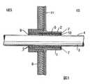
図1は導路1を示し、導路1は熱安定性であり、本実施例では金属製である。導路1は内壁2を有し、内壁2は単一の管3が貫通して延在する内部空間を画成する。管3は熱弱化可能な管であり、外壁4を有する。外壁4は、たとえば、PVC製またはポリエチレン製の管であってもよい。しかしながら、熱弱化可能な管は補強剤としてガラス繊維を包含していてもよい。そのような管はガラス繊維を包囲する樹脂を包含していてもよい。 FIG. 1 shows a
熱膨張可能な防火システム5が導路1内に配置されている。この実施例では、システム5は装置6を備え、装置6は非線形熱膨張特性を有する少なくとも1つの構成部品を備える。図示したように、装置6は、管3の周りに同心円状に、配置可能であり、システム5を配置し終わり、かつ装置の非線形的熱膨張が開始する前に、導路の外からの熱ガスが装置6と導路1の内壁2の間のガス入口空間7に入ることができるようになっている。 A thermally expandable
装置6は、同装置がその非線形膨張特性を発揮する温度範囲の最下端より低い温度で溶融を開始する表面を有する。 The
理解されるように、近傍の火災により存在するような熱ガスがガス入口空間7に入ると、装置6の最初の応答は、この熱ガスとの相互作用により加熱されつつある表面の溶融である。この結果、装置6の表面は粘着性物質を形成する。導路1の内壁2への装置6の付着が起きる。装置6は、おそらく未だ非線形膨張の領域内ではないとしても、すでに少し膨張することできるので、装置6は導路1内にそれ自体がしっかりと固定される。熱も管3を介して導路1内に伝達される。管3がその弱化を開始する温度に達する前に、装置の表面が溶融を開始する温度に達する。したがって、装置6は管3の外層4にそれ自体付着する。装置6はそのとき導路1内でその内壁2、管3、外壁4にしっかりと固定される。As will be appreciated, when hot gas, such as is present by a nearby fire, enters the
近傍の火災による熱にさらにさらされると、導路1の温度がさらに上昇する。例えばプラスチック製の熱弱化可能な管3は約75℃以上の温度にさらされると柔軟になる。ある段階で、装置6は非線形熱膨張が開始する温度に達する。装置6はそれ自体が導路1の内壁2および管3の外壁4に固定されるので、軸線方向の膨張が制限される。しかしながら、半径方向内方の膨張は、特に弱化した管3により、比較的容易である。実際上、装置6は弱化した管3を「崩壊」させ、そのまま導路1を完全に閉鎖する。 When further exposed to heat from a nearby fire, the temperature of the
半径方向内方の膨張は強制的であり、非線形膨張の結果膨張した装置が管3を崩壊させて導路1を閉鎖するだけでなく、それ自体を導路1内に「取り外しできないように」締着される程度にすることができることが分かった。導路の閉鎖はその場合、水密である。閉鎖された導路から膨張した装置を取り外すには専用の工具が必要である。このことは隔離されたコンパートメント内で火災が起きた場合に非常に有利である。例えば、火災が船舶の機関室に起き、そして導路が上述のように閉鎖され、機関室に水を満たして火災を鎮火したときは、必ずしも水が機関室から導路を介して船舶全体に浸透するとは限らないからである。 The radially inward expansion is compulsory and the device expanded as a result of the non-linear expansion not only collapses the
図1に示すように、導路1の一方の側に断熱材料8が適用される。導路1が壁11に適用されると、この材料は導路1の直接火または熱にさらされない側に通常適用される。この熱にさらされない側は図面ではUESで示され、非暴露側(UnExposed Side)を表す。 As shown in FIG. 1, a
近傍の火災から生じる熱に直接さらされる側はESと呼ばれ、暴露側(Exposed Side)を表す。導路1が金属製または金属合金製である場合に適用される断熱材料8は通常ミネラルウールを主成分としている。 The side directly exposed to the heat generated from the nearby fire is called ES and represents the exposed side. The
特に、熱への暴露が導路1の一方の側のみに起きる場合は、システム5の実際の応答は導路1に対して非対称的となる。システム5の応答部分は、特に、膨張する装置6により管3が十分に閉鎖されると、断熱性をも提供する。導路1の他の側(ES)が近傍の火災に暴露されている間、火災が起きない導路の側(UES)の温度の上昇は60〜70℃よりそれほど高くはならないことが分かっている。これは、特に断熱材料8が導路1の非暴露側に適用されている場合に該当する。 In particular, if the exposure to heat occurs only on one side of the
また、おそらく、装置6の一部分が導路1内で早期に固定されることにより得られる断熱の結果、装置6の完全に膨張した部分と装置6の膨張していないか、またはわずかに膨張した部分との間の移行は急激であることが分かっている。明らかに、熱は局在化されたままであり、ES側における装置の完全膨張に利用可能でありかつ使用される。 Also, perhaps as a result of the thermal insulation obtained by premature fixing of a portion of the
後にさらに詳しく説明するが、この装置は好ましくはスリーブの形状を有する。しかしながら、装置6の他の形状も可能である。この装置は好ましくは硬化可能なゴム状化合物製であり、所定の形状に押し出されている。成分の1つは例えばエチルビニルアセテート・ポリマー(EVA)であってもよく、エチルビニルアセテート・ポリマー(EVA)は約60℃で溶融を開始する。非線形熱膨張特性を有する化合物は、当技術において周知であり種々の等級で市販されている熱膨張可能なグラファイトを包含していてもよい。装置6のさらなる情報については、例えば国際出願公開第WO03/013658号パンフレットを参照されたい。 As will be described in more detail later, this device preferably has the shape of a sleeve. However, other shapes of the
この化合物は第1の種類の膨張剤と第2の種類の膨張剤と、たとえば、第1の種類の熱膨張可能なグラファイトと第2の種類の熱膨張可能なグラファイトとを含むことが可能である。第1の種類は例えば第2の種類が膨張を開始する温度よりも低い温度で膨張を開始するものであってよい。当技術の専門家にとっては、装置が熱ガスにさらされると溶融を開始し、その結果それ自体が他の表面に固着する材料を見つけ出すことは、通常の実験的作業の範囲内であろう。1種または2種以上の(当技術において知られた)膨張剤は、装置6が高温にさらされると、装置6が非線形的にかつそれらの表面に対して垂直な方向に膨張を開始することを確実にする。 The compound can include a first type of expander and a second type of expander, for example, a first type of thermally expandable graphite and a second type of thermally expandable graphite. is there. For example, the first type may start expansion at a temperature lower than the temperature at which the second type starts expansion. For those skilled in the art, it would be within the scope of normal experimental work to find a material that will begin to melt when the device is exposed to hot gas and as a result will itself adhere to other surfaces. One or more expansion agents (known in the art) cause the
図1に示す導路は船舶の甲板および/または海洋建築物に典型的に見られる。導路1はコンパートメント同士の間の金属壁11または隔壁11に配置、溶接されていてもよい。しかしながら、そのような構造の外壁11内に配置されていてもよい。 The conduit shown in FIG. 1 is typically found on ship decks and / or offshore buildings. The
次に、図1に示す導路1に適用可能なシステム5の多くの他の実施の形態について説明する。 Next, many other embodiments of the
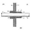
図2はシステム5の一実施の形態であり、このシステムはさらにシーラント9を備え、導路1の一端をシーラントの層10を適用することにより密封している。図2に示す実施の形態において、シール層10は好ましくは厚さが15mmより大きい。そのようなシーラント9は出願人により商標名「FIWA」で市販されている。シーラントは室温で湿気にさらされると硬化可能である。そのようなシーラントは市販されている。シーラント9はさらに熱的に実質的に形状保持かつ寸法保持型であり、硬化後シーラントの硬度がShoreAの45〜60℃の範囲内であるようなものであってもよい。そのようなシーラント9はケイ素を主成分とするものであってもよく、例えば「NOFIRNO」という商品名で販売されるパテとして市販されている。シーラント9は厚さ15mm〜20mmの層10として適用することができ、本発明では、導路1の近傍の火災に直接さらされることが考えられない側(UES)にのみ適用されるべきである。図2において、UESは断熱材料8が適用されている側である。 FIG. 2 is an embodiment of the
図2に示されるシステム5の応答は図1に示されるシステム5の応答と同様である。主な差異は、図2に示される実施の形態においては、熱ガスまたは煙が暴露側から非暴露側に移動することができないことである。これはシーラント層10が導路1のUES端を遮断してそのようなガスを通さないからである。熱ガスの暴露によって、装置5の一部分のみ、すなわち暴露側に位置した部分が上述のように応答すると、より非暴露側に位置したガス入口空間7の部分が空洞を形成することが可能である。これは装置5の部分が暴露側で内壁2と外壁4にしっかりと固着したためである。そのようなUES端の空洞は完璧な断熱体を形成する。非暴露側の管の温度は、暴露側が実際に近傍の火災にさらされると、図1に示す状況と比べてずっと長く低いままである。 The response of the
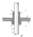
図3はシステム5の他の実施の形態を示す。この導路1において、導路1の各端部は厚さが約5mm以下のシーリングを備え、そのため近傍の火災にさらされると、装置5の非線形膨張が始まる前に、依然として熱ガスが導路1の外部からガス入口空間内に入ることができる。シーラントを導路1の一端のみに適用することが可能である。厚さが約5mm以下のシーラント層は近傍の火災により消耗され、破損したりまたは裂けたりその他により熱ガスの通り道となり、熱ガスはガス入口空間7に入る。図3に示すシステム5の応答は図1に示すシステム5の応答と本質的に同じである。差異は、図3に示すシステム5は装置6の外表面がガス入口空間7に入る熱ガスによって加熱されるのに若干時間がかかることである。しばらくの間、薄いシーラント層10はガスが導路1内に入るのを阻止する。しかしながら、ひとたびシーラント層10が、たいがい暴露側のみにおいて、崩壊すると、熱ガスが入口空間7に入り、これに続いてシステムの上述の応答が起きる。 FIG. 3 shows another embodiment of the
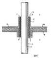
図4は図3に示すシステム5と同様のシステムの一実施の形態を示す。しかしながら、システム5は、ガス入口空間7が、装置6と導路1の内壁2との間ではなく、管3の外壁4と装置6との間にあるように存在するか、または適用されている。特に、導路1が比較的高い熱伝導率を有する壁11、例えば鋼または真鍮製の壁内に配置され、かつ導路1自体が熱伝導性材料、例えば金属、金属合金等で作製されている場合、導路1の内壁2に面し、おそらくこれと接してさえいる装置6の表面は導路1により加熱され、導路1に固着される。暴露側でシーラント層10の「崩壊」後、熱ガスはガス入口空間7に入り、チューブ3の外壁4に面する装置6の表面を加熱することができる。次いで、その表面の管3の外壁4への固着が起き、ついでその状態の装置が導路1内に完全に固着される。さらに熱にさらされると、再び半径方向の膨張が、阻止された軸線方向の膨張に対して、優勢となる。 FIG. 4 shows an embodiment of a system similar to the
図5はシステム6の一実施の形態を示し、この実施の形態では、暴露側のシーラント層10の「崩壊」後に熱ガスがガス入口空間7に入ると、ガス入口7は装置6を経由する。装置6の他の表面に面している装置6の表面は溶融し、相互に接着する。導路1の内壁2に面している装置6の表面は加熱され、図4に示すシステムの動作を説明したときに上述したように内壁2に固着される。管3の外壁4に面した装置6の表面は管3を介して導路に輸送された熱により加熱される。最終的に、この装置6もそれ自体導路1の内壁2および管3の外壁4に固着し、そのままさらに熱にさらされ、温度が上昇した際に軸線方向の膨張を阻止し、半径方向内方の膨張を助ける。 FIG. 5 shows an embodiment of the
異なる実施の形態は同様の温度プロフィルにさらされた際に異なる応答をする。しかしながら、結局、最終的結果は実質的に同じである。 Different embodiments respond differently when exposed to similar temperature profiles. In the end, however, the end result is substantially the same.
留意すべきことに、導路1のUES端に適用された単一の比較的厚いシーラント層10(図2に示す)を図3、4および5に示す装置6の実施の形態のいずれかと組み合わせることが可能である。同様に、図3、4および5に示す装置6の実施の形態をシーラント層10なしで図1に示す実施の形態と同様の方法で適用することもできる。 It should be noted that a single relatively thick sealant layer 10 (shown in FIG. 2) applied to the UES end of the
図6〜10はそれぞれ図1〜5に対応する実施の形態である。しかしながら、図6〜10において導路は甲板または天井12に適用される。天井側はCで示され、床側はFで示される。管3および導路1の軸線方向は垂直方向である。これら図6〜10のそれぞれから分かるように、通常と同様に、断熱材料8が天井12に対して適用されている。システム5はさらに熱ガスが床側Fからでなく天井側Cから入るように適用される。厚い単一のシール層10が適用されている図7に見られるように、これは床側Fに適用されている。明らかに、図6〜10に示す実施の形態は、熱ガスが天井側Cからガス入口空間7に入ることを見込んでいる。装置6は材料自体が導路1の内壁2に対しておよび/または管3の外壁4に対して、導路内に安定して締着されるように作製することができる。しかしながら、装置6は他の手段により導路1内に保持されるようにすることも可能である。そのような手段は例えば両面テープ用の粘着材料であってもよい。図8〜10に示す実施の形態は、天井側Cにおいてシール層10の適用により装置6を導路内に保持することができる方法を示す。 6 to 10 are embodiments corresponding to FIGS. However, in FIGS. 6-10, the conduit is applied to the deck or
導路1は床/天井12に対して対称に配置することが可能であるが、導路は完全に天井側に、または完全に床側に延在していることも可能である。これら2つの極端の間のすべての構造がひとしく可能である。図1〜10に示す構造は船舶および/または他の海洋建築物の甲板に一般に見られる。 The
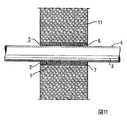
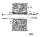
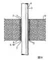
図11〜20は図1〜10にそれぞれ示すものと本質的に同じシステム5を示す。主な差異は、導路が、石やコンクリート製の壁(図11〜15)のような熱伝導率の比較的低い壁11内に配置されるか、あるいはその材料の床または天井(図16〜20)内に配置されるかである。通常、導路1はそのような状況では石製またはコンクリート製のように比較的に熱伝導率の低い材料から実質的に作製されている内壁2を有する。それらの状況では、導路は石またはコンクリート壁の開口部または孔に他ならない。留意すべきことに、導路1に熱を輸送する主なルートはこれらの場合は管と、熱ガス入口空間7と、管3である。しかしながら、導路1はこの場合も鋼や真鍮のような比較的に熱伝導率の高い材料から実質的になる内壁を、例えばコンクリート中に鋳込まれるようにすることも不可能ではない。 FIGS. 11-20 show a
導路1の直径は管3の直径に対して比較的に小さい。好ましくは、管3の外径は導路1の内径の50%より大きい。さらに好ましくは、管の外径は導路1の内径の60%より大きい。管の外径が導路1の内径の70%より大きいときにさらなる最適化が達成される。もちろん、管3の外径が導路1の内径に対して大きいほど、より大きな空間が確保される。図1〜10に示すパーティション10は金属合金製、一般的には鋼、アルミニウムまたは銅合金製であってもよい。しかしながら、図11〜20に示すように、パーティション自体は石もしくはコンクリート壁、床または天井を包含してもよい。その場合、導路1はおそらく石またはコンクリート壁の貫通孔からなる。パーティションが石またはコンクリート壁であるとき、通常は断熱材料がパーティション1のいずれの側にも適用されない。 The diameter of the
導路1が金属合金製であるとき、導路1の長さは約18cmであってもよい。導路が石またはコンクリートのパーティション中の貫通孔を主体としているときは、導路1の長さは約15cmと短くすることができる。遮断システムは導路の各タイプ、金属または石/コンクリートについて本質的に同じである。 When the
熱膨張可能な装置6の層は単一部品装置であってもよい。熱膨張可能な装置6は非線形熱膨張特性を有する少なくとも1つの部品を含み、この部品は熱膨張可能なグラファイトの形であってもよい。この装置は非膨張製材料製であることが好ましい。 The layer of thermally
シーラント9は耐熱性ポリマー製および熱的に形状保持タイプかつ寸法保持タイプであってもよく、好ましくはポリマーを包含する。このポリマーは加熱時に該ポリマー自体がそのような加熱時に膨張する程度よりも大きく膨張させる成分を含まないものである。好ましくは、このポリマーはシリコンを主体とするポリマーである。理想的にはこのシーラントは400℃の温度において非引火性である。さらに、シーラントが周知の国際的に認められた酸素指数の測定方法により決定された酸素指数が45%以上の高さであると、利用上有利である。 The
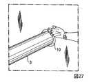
次に、図21〜28を参照すると、剛性導路1内の防火システムを提供する方法の例示的一実施の形態が開示されている。石またはコンクリートのパーティション11における導路1が図示されているが、パーティション11と導路1が金属合金製であるときは、この方法は本質的に同じである。導路は天井または床に同様に適用することができる。 Referring now to FIGS. 21-28, an exemplary embodiment of a method for providing a fire protection system in
図21は導路1に熱弱化可能な材料製の管3が貫通しているパーティション11を示す。図22に示すように、この方法の一工程は非線形熱膨張特性(図示しない)を有する少なくとも1つの成分を含む装置5を適用することを含む。装置5は管3の周りに事実上同心円状に適用される。装置5は図22に示すようにスリーブの形をしており、管3の周りにスリーブを都合よく操作するためのスリット13を有していてもよい。図23に概略を示すように、スリーブを操作して管3の周りに配すると、この管が導路1内に押込まれる。好ましくは、このスリーブは導路の中央に行き着き、導路の各端部には依然としてシーラント9が占めることができる空間の存在を許容し、そのためシーラント9は導路1に入り、パーティション11と同一面になる。図24は装置6を管3の周りに同心円状に適用した最終結果を示す。装置6の配置は、装置の非線形熱膨張の開始前に、熱ガスが装置6と導路1の内壁2との間の熱ガス入口空間内に入ることができるように、配置されている。 FIG. 21 shows a
図25に示すように、シーラント9は次の工程で導路1と管3との間の導路1の一(または両)端において適用される。前述したように、このシーラント9は耐火性ポリマーからなり、室温で湿気にさらされると硬化可能である。シーラント9はさらに熱的に実質的に形状保持かつ寸法保持タイプであってもよく、硬化後、シーラントは硬度がShoreA硬度45〜60の範囲内のものである。このシーラントの適用は例えばシーラントディスペンサー14を用いて行うことができる。シーラント9は、シーラント9で充填することができる導路1の体積に対してたっぷりと適用してもよい(図25に示すように)。余分のシーラント9は設置作業の間に容易に除去することができる。残っているシーラント9は圧しつけて平坦にすることができる(図27)。手を例えば水で湿らせて、シーラントが作業者の手に接着しないようにすることが好ましい。最後に、シーラント9は、この場合、パーティションと同じ面になるようにする。本明細書に開示したようなシステム6を中に設置した導路1を設けたパーティション11を図28に示す。導路1が鋼または金属(合金)製の場合、シーラントは導路1の各端縁と同じ面になるようにする。 As shown in FIG. 25, the
上述のように、シーラント層10は導路の一方の端部のみに適用することができる。その場合、その端部は近傍の火災に直接さらされることが予想される端部と反対側の端部でなければならない。シーラント層はその場合厚さが25mmより厚く、理想的には約20mmになるように適用することができる。シーラント層10を導路1のそれぞれの端部に適用することも可能である。その場合、シーラント層10の厚さは約5mm以下でなければならず、そのため近傍の火災にさらされると、非線形膨張装置6の膨張が開始する前に依然として導路1の外部から熱ガスが熱ガス入口空間7に入り込むことができる。 As described above, the
上述のように、コンクリートまたは石壁11の貫通孔である導路1に使用するためのものとして説明されたシステム5と、金属または金属合金製のパーティション11の一部分としての、金属または金属合金製の導路1に使用するためのものとしてのシステム5は本質的に同じである。重要なのは、導路1へ、特に装置6の表面への熱の伝達に使用できる経路はこれら2つのタイプの導路1同士の間で異なっていることである。金属または金属合金製パーティションの一部分であり、かつそれ自体金属または金属合金製である導路1はパーティションの材料および導路の材料を介して並びに熱に暴露される側ESから導路1内に延びている管3を介して熱の伝達が可能である。換言すると、この場合、2つの経路が使用できる。一方、石またはコンクリート製パーティション11の貫通孔である導路1は導路への熱の伝達用に1つの経路だけ使用可能であり、この経路は管自体により提供される経路である。コンクリートまた石製パーティション11は最初に長時間熱を吸収してから導路1への熱の伝達を開始する。コンクリートまたは石製壁自体から導路への熱の伝達が起きるときまでに、熱弱化可能な管、チューブまたはダクトはすでにかなりの程度まで弱化している。 As described above, the
興味深いことに、上述のシーリングシステム5はこれらのタイプの導路1のそれぞれに対して適用可能であることが分かっている。もちろん、導路1が金属または金属合金製であり、かつ金属または金属合金製パーティションの一部分である場合、熱は非常に速く導路に入り、熱膨張可能な装置6は迅速に応答する。しかしながら、不利なことに、鋼または金属製導路1は常に腐食されやすい。 Interestingly, it has been found that the
上述のシーリングシステムは導路がコンクリートまたは石製の壁の貫通孔であるときも十分迅速に応答することが分かっている。 The sealing system described above has been found to respond quickly enough when the conduit is a through hole in a concrete or stone wall.
上述のことから、本発明によるシステムのさらなる利点は、異なるタイプの導路1に対して1つのシステムが用意されていることである。これらの導路1は概略を説明したように導路への熱伝達に利用可能な経路が異なることである。 From the above, a further advantage of the system according to the invention is that one system is provided for different types of
上述したように、導路1の実際の長さは導路1の異なるタイプに対して異なっていてもよい。一般に、石またはコンクリート製壁の貫通孔からなる導路1の長さ約15cmまで短くすることができる。例えば海洋および船舶産業用のような鋼構造物に使用される導路1の長さは約18cmまで短くすることができる。種々の寸法の管、すなわち外径の異なる管が利用できるので、かつ種々の寸法の導路、この場合種々の内径の導路が利用できるので、装置5は単一層スリーブとして設けられ、実質的に軸線方向に延びているスリット13を有し、下記の可能性の1つに従う寸法を有する。明らかに、装置の長さはあまり短くすることはできない。結局、管を「崩壊(crush)」させ、かつ導路を閉鎖するのに十分な熱膨張可能な材料が存在していることが必要である。熱にさらされた際の膨張は原体積の5〜40倍の範囲内にすることができる。 As described above, the actual length of the
装置6は、スリーブの形状の場合は、長さが約170mmであってもよく、直径25mmの管用では、スリーブ材料の厚さが約2mmであってもよく、25〜50mmの管用では厚さが約4mmであってもよく、51〜74mmの管用では厚さが約6mmであってもよく、75〜109mmの管用では厚さが約8mmであってもよく、110〜124mmの管用では厚さが約14mmであってもよく、125〜139mmの管用では厚さが約18mmであってもよい。 The
直径が140〜160mmの管については、スリーブ材料の厚さは好ましくは約20mmである。そのとき、スリーブの長さは好ましくは190mmである。 For tubes with a diameter of 140-160 mm, the thickness of the sleeve material is preferably about 20 mm. At that time, the length of the sleeve is preferably 190 mm.
ガス入口空間7は横断方向において、「ギャップサイズ」が、外径2インチ(2´´)までの管については好ましくは3mm以下であり、2インチ〜4インチまでの管については6mm以下であり、6インチまでの管については10mm以下である。 In the transverse direction, the
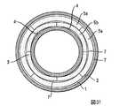
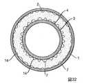
次に図29〜33を参照してシステム5の一部分としての装置6の種々の実施の形態を説明する。装置6はスリーブの形状をしていてもよいことはすでに説明がなされている。 Various embodiments of the
図29はスリーブ6が間に配置されている導路1および管3の概略横断面図である。装置6は例えば図30および31に示すように多部品装置であってもよい。図30および31に示すスリーブはそれ自体が管3の周りを「締め付ける(clamp)」。しかしながら、スリーブはそれ自体が導路の内壁に対して締付けて、ガス入口空間7が装置6と管3の間に存在するようにすることも可能である。図31に示す装置は半径方向に間隔をあけて配置された部分5a、5bからなる。図32に示す装置は使用時にガス入口空間7となる多数のチャネル14を設けられている。図33は巻き付け可能な装置である装置6を示し、装置6は非線形熱膨張特性を有するゴム様材料性のシートを1枚または2枚以上備えている。 FIG. 29 is a schematic cross-sectional view of the
装置6は幾何学的には同心円状に配置可能であるが、実際上は精確に同心円状に配置される訳ではない。例えば、スリーブ形状の装置6は水平方向を向いた管3の周りに「ゆるく(loosely)」取り付けられていてもよい。 Although the
種々の形状が可能である。装置6はガス入口空間7が環状体積内に位置する種々の接線距離にある体積部分を含むように構成することができる。このようにする利点は、装置6がその外周から熱ガスによって加熱され、装置が局所的に面している表面の多数の位置で急速にそれ自体が固着することが可能となることである。 Various shapes are possible. The
図31および33に示すように、装置6は、ガス入口空間7が環状体積内の種々の半径方向の距離に位置する体積部分を含むように構成することもできる。これも例えば図32に示す実施の形態に適用することができる。図33に示す実施の形態は単一の部品であってもよいが、多部品装置であってもよい。各装置6は同心円状に管3の周りに配置可能であるが、装置6の部品15は必ずしも丸みを帯びていなくてもよい。図31に示す装置6の実施の形態はアーチ形部品からなるが、各部品5a、5bは管3と導路1の内壁2との間の環状空間内に挿入するために弛緩した状態で平坦および屈曲可能であるようにすることが可能である。 As shown in FIGS. 31 and 33, the
本発明による防火システム5は、上述の単一の管3の代わりに、管3の単一の束が存在する場合にも適用することができることが分かっている。図34はそのような適用を示している。束33の管3のそれぞれは比較的に熱弱化可能な管3である。管3は好ましくは緊密に束ねられ、束33の管3同士の間に大きなギャップが生じないようにしている。1つの図、すなわち図34のみがそのような束33を示しているが、他の図のそれぞれにおいて単一の管3は管3の単一の束33に置き換えることができることが指摘される。 It has been found that the
管3は事実上、例えば冷却された送水管であり、図35に示すように、そのようなものとしてアーマフレックスのような断熱材料35を設けられている(断熱材料35は明瞭さのために厚い層として図示されるが、実際には必ずしも該当しない)ことが考えられないことはない。 The
本発明は上述の実施例に限定されない。ガス入口空間7は装置6の多くの異なる形状、および/または装置6の部品に従って形成することができる。好ましくは、ガス入口空間7は環状スリットの形状を有し、好ましくは上述のギャップを持つ。当業者は導路1のタイプと管3および導路1の大きさに関連してガス入口空間の最適の寸法を容易に算出することができる。明らかに、装置6がそれ自体を導路1内に固定することができないほどガス入口空間7は大きすぎてはならず、また小さすぎたり狭すぎたりしてはならない。ガス入口空間に入る熱ガスの体積は装置6の表面の加熱が可能になるように十分でなければならない。 The present invention is not limited to the embodiments described above. The
管と導路はすべて円筒形状として図示されているが、導路および/または管がこの理想的な形状から偏向した形状を有していることも考えられないではない。 Although the tubes and conduits are all illustrated as cylindrical shapes, it is not unimaginable that the conduits and / or tubes have shapes that deviate from this ideal shape.
上述のことから明らかなように、システム5の装置6は、使用時に、好ましくは完全に円筒状であり、いかなる部分も軸線方向の局部的にさえも、半径方向に沿ってかなりの程度延在していることがない。換言すれば、好ましくは、使用時、装置6の軸線方向に沿った各半径方向の断面が、軸線方向に沿った他の任意の断面と同一ではないにしても類似している。 As is clear from the above, the
装置6の両端部は、使用時、好ましくは同じである。システムのそのような対称性は火災がいずれの側でも起き得ること、かついずれの側で火災がより起こりやすいかはしばしば全く予想できないことを反映している。 Both ends of the
本発明によるシステムの一部分である装置6は好ましくは押し出し可能であり、このこともすぐ前に概略説明した幾何学的選好のさらなる利点である。このことは必ずしもそのような装置6の各実施の形態を押出しすることが経済的に実行可能であることを意味しない。押出し可能性はど事実上、装置6の形状を特徴付けている。すなわち、装置6は形状の観点から押出し可能である。 The
さらに、システム5が導路に適用される前に、管がすでに導路を貫通して延在していることは必ずしも該当しないことを留意すべきである。最初に装置6が導路内に配置され、その後にだけ管3が導路1内に挿入されるようにすることが可能である。好ましくは、装置6はそのような場合、導路1の内壁2に対して「締付固定される(clamped)」。装置6が作製される材料は好ましくは耐火性材料である。難燃性ゴム様材料については国際出願公開第WO01/09538号パンフレットおよびその中に記載されている引例を参照されたい。 Furthermore, it should be noted that it is not necessarily the case that the tube already extends through the conduit before the
そのような変形例および変更例は、特許請求の範囲に記載された本発明の範囲内に入ると了解される。 Such modifications and variations are understood to fall within the scope of the present invention as set forth in the appended claims.
Claims (20)
Translated fromJapanese前記内部空間は、前記管を崩壊させ、かつ前記熱安定性導路を閉鎖することが可能な非線形熱膨張特性を有する少なくとも1つの部品を含む少なくとも1つの熱膨張可能な装置を含むシステムを備え、前記装置は、前記装置がその非線形膨張特性を示す温度範囲の最下端における温度よりも低い温度において溶融を開始する表面を有し、次いで前記表面は粘着性物質を形成し、前記装置は所定の形状に押し出しされた硬化可能なゴム様化合物から作製されたものであり、かつ前記装置は前記内部空間に対して同心円状に配置されて前記単一の管または前記複数の管からなる単一の束を同心円状に包囲し、
前記装置の前記非線形熱膨張の開始前に、前記導路の外部から熱ガスが前記装置と前記導路の内壁との間の、前記単一の管の外壁、もしくは前記複数の管からなる単一の束の外壁と前記装置との間の、あるいは前記装置を貫通するガス入口空間内に入ることができるように、
前記粘着性物質を前記装置の表面に形成することができるように、かつ
前記装置はそのときそれ自体が前記導路内にしっかり固定可能であるように
配置されていることを特徴とする導路。A single tube or a single tube bundle of tubes extends through or has an inner wall that defines an interior space that extends in the future, each tube having a relatively heat-damped outer wall In a rigid and thermally stable conduit, which is a possible tube
The internal space comprises a system includingat least one thermally expandable device includingat least one component havinga non-linear thermal expansion characteristiccapable of collapsing the tube and closing the thermally stable conduit. The device has a surface that begins to melt at a temperature lower than the temperature at the lowest end of the temperature range in which the device exhibits its nonlinear expansion characteristics, and then the surface forms an adhesive material, The device is made from a curable rubber-like compound extruded into the shape of the unit, and the device is concentrically arranged with respect to the internal space and comprises the single tube or the plurality of tubes A concentric circle around the bundle,
Before the start of the nonlinear thermal expansion of the device, hot gas from the outside of the conduit passes between the device and the inner wall of the conduit, the outer wall of the single tube or the single tube comprising the plurality of tubes. In order to be able to enter the gas inlet space between the outer wall of one bundle and the device or through the device,
A conduit characterized in that the adhesive substance can be formed on the surface of the device and the device is then arranged such that it can be firmly fixed in the conduit .
前記内部空間内に、前記管を崩壊させ、かつ前記熱安定性導路を閉鎖することが可能な非線形熱膨張特性を有する少なくとも1つの部品を含む熱膨張可能な装置を配置し、前記装置は、前記装置がその非線形膨張特性を示す温度範囲の最下端における温度よりも低い温度において溶融を開始する表面を有し、次いで前記表面は粘着性物質を形成し、前記装置は所定の形状に押し出しされた硬化可能なゴム様化合物から作製されたものであり、
前記単一の管または前記管の単一の束を同心円状に包囲するように、前記装置を前記内部空間に対して同心円状に配置し、
前記装置を、
前記装置の前記非線形熱膨張の開始前に、前記導路の外部から熱ガスが前記装置と前記導路の内壁との間の、前記単一の管の外壁、もしくは前記管の単一の束の外壁と前記装置との間の、あるいは前記装置を貫通するガス入口空間内に入ることができるように、
前記粘着性物質を前記装置の表面に形成することができるように、かつ
前記装置がそのときそれ自体が前記導管内にしっかり固定可能であるように
配置することを特徴とする方法。A single tube or a single bundle of tubes extends through or has an inner wall that defines an interior space that will extend in the future, each tube having a relatively heat-damped outer wall A method of providing a fire barrier in a rigid conduit, which is a possible tube, the method comprising: nonlinear heatcapable of collapsing the tube and closing the thermally stable conduit in the internal space. Arranging a thermally expandable device comprising at least one component having expansion properties, the device having a surface that begins to melt at a temperature lower than the temperature at the lowest end of the temperature range in which the device exhibits its nonlinear expansion properties. And then the surface forms an adhesive material, and the device is made from a curable rubber-like compound extruded into a predetermined shape,
Arranging the device concentrically with respect to the interior space so as to concentrically surround the single tube or single bundle of tubes;
Said device,
Before the start of the nonlinear thermal expansion of the device, hot gas from the outside of the conduit passes through the outer wall of the single tube or a single bundle of tubes between the device and the inner wall of the conduit. In order to be able to enter a gas inlet space between the outer wall of the device and the device or through the device,
A method characterized in that the sticky substance can be formed on the surface of the device and that the device is then itself securable in the conduit.
前記導路の少なくとも一端において、シーラント層を含むシーリングを適用することを特徴とする請求項17記載の方法。The method further comprises:
The method of claim 17, wherein a seal including a sealant layer is applied at at least one end of the conduit.
Applications Claiming Priority (3)
| Application Number | Priority Date | Filing Date | Title |
|---|---|---|---|
| GB0800765.0 | 2008-01-16 | ||
| GBGB0800765.0AGB0800765D0 (en) | 2008-01-16 | 2008-01-16 | Fire-stop system for placement in a conduit through which a thermally weakenable pipe extends, method for placing the system and conduit provided |
| PCT/EP2009/050499WO2009090247A1 (en) | 2008-01-16 | 2009-01-16 | Fire-stop system for placement in a conduit through which a thermally weakenable pipe extends, method for placing the system and conduit provided with such a system |
Publications (3)
| Publication Number | Publication Date |
|---|---|
| JP2011509728A JP2011509728A (en) | 2011-03-31 |
| JP2011509728A5 JP2011509728A5 (en) | 2013-07-04 |
| JP5312480B2true JP5312480B2 (en) | 2013-10-09 |
Family
ID=39165852
Family Applications (1)
| Application Number | Title | Priority Date | Filing Date |
|---|---|---|---|
| JP2010542641AActiveJP5312480B2 (en) | 2008-01-16 | 2009-01-16 | A fire prevention system in which a heat degradable tube is disposed in a conduit extending therein, a method of arranging the system, and a conduit including the system |
Country Status (9)
| Country | Link |
|---|---|
| US (1) | US8393121B2 (en) |
| EP (1) | EP2203671B1 (en) |
| JP (1) | JP5312480B2 (en) |
| KR (1) | KR101516172B1 (en) |
| CN (1) | CN101855483B (en) |
| BR (1) | BRPI0904966B1 (en) |
| ES (1) | ES2392377T3 (en) |
| GB (1) | GB0800765D0 (en) |
| WO (1) | WO2009090247A1 (en) |
Families Citing this family (35)
| Publication number | Priority date | Publication date | Assignee | Title |
|---|---|---|---|---|
| EP2327453B1 (en) | 2009-11-27 | 2012-12-26 | Beele Engineering B.V. | Passive fire resistant system for filling a space or gap confined by construction elements |
| JP2011257001A (en)* | 2010-05-13 | 2011-12-22 | Sekisui Chem Co Ltd | Construction structure of replacement pipe and floor slab penetration piping material used for the construction structure |
| NO334530B1 (en)* | 2010-12-14 | 2014-03-31 | Beerenberg Corp As | A fire-resistant steel structure and detachable coverings for fire protection of steel structures |
| CN102182873B (en)* | 2011-03-22 | 2013-01-16 | 广东联塑科技实业有限公司 | Novel method and device for filling fire retardant ring core |
| CA2786194C (en)* | 2011-09-16 | 2019-01-15 | Hilti Aktiengesellschaft | Fire-prevention sleeve, use of the fire-prevention sleeve, method for installing a fire-prevention sleeve, and ceiling passage |
| DE102011084057A1 (en)* | 2011-10-05 | 2013-04-11 | Hilti Aktiengesellschaft | Holder for a fire sleeve and use of this holder |
| DE102012212832A1 (en)* | 2012-07-23 | 2014-01-23 | Hilti Aktiengesellschaft | Assembly for a cable feedthrough |
| EP3003717B1 (en) | 2013-06-06 | 2020-02-19 | 3M Innovative Properties Company | Articles and methods of wrapping a substrate with a polymeric structure |
| NL1040462C2 (en)* | 2013-10-18 | 2015-04-23 | Beele Eng Bv | A pipe transit system for plastic pipes. |
| NL1040459C2 (en) | 2013-10-18 | 2015-04-23 | Beele Eng Bv | A pipe transit system. |
| US9853267B2 (en) | 2014-02-03 | 2017-12-26 | Ursatech Ltd. | Intumescent battery housing |
| US9089726B1 (en) | 2014-05-16 | 2015-07-28 | Pyrophobic Systems, Ltd. | Passthrough firestops |
| EP2974774A1 (en)* | 2014-07-15 | 2016-01-20 | HILTI Aktiengesellschaft | Fire resistant tape |
| US9517369B2 (en) | 2014-08-12 | 2016-12-13 | Stephen Samouhos | Fire stop conduit |
| US9803845B2 (en) | 2014-11-26 | 2017-10-31 | Ursatech Ltd. | Downlight firestop |
| US9797563B2 (en) | 2014-11-26 | 2017-10-24 | Ursatech Ltd. | Downlight firestop |
| US10704751B2 (en) | 2014-11-26 | 2020-07-07 | Ursatech Ltd. | Downlight firestop |
| JP6616580B2 (en)* | 2015-03-17 | 2019-12-04 | 三菱航空機株式会社 | Aircraft safety equipment |
| CN107466243B (en)* | 2015-04-17 | 2021-06-04 | 3M创新有限公司 | Penetration fire-retardant system |
| US10823313B2 (en)* | 2015-04-17 | 2020-11-03 | 3M Innovative Properties Company | Smoke and sound barrier for a building penetration |
| EP3088783A1 (en)* | 2015-04-27 | 2016-11-02 | Hilti Aktiengesellschaft | Flame retardant sleeve |
| RU2699153C2 (en)* | 2015-06-19 | 2019-09-03 | Роквул Интернешнл А/С | Intumescent fire-prevention coupling, roll of several intumescent fire-fighting couplings and method of installing intumescent fire-fighting coupling |
| US10363444B2 (en)* | 2015-09-30 | 2019-07-30 | Specified Technologies Inc. | Self-adjusting firestopping sleeve apparatus |
| EP3366964A1 (en)* | 2017-02-22 | 2018-08-29 | HILTI Aktiengesellschaft | Fire retardant element |
| CA3002182A1 (en)* | 2017-04-21 | 2018-10-21 | Jonathan A. Goubault | Pipe with securing plate |
| WO2019028128A2 (en) | 2017-08-04 | 2019-02-07 | Thomas & Betts International Llc | Conduit assembly providing a thermal break through an opening in an insulated panel |
| NL1042540B1 (en)* | 2017-09-11 | 2019-03-19 | Beele Eng Bv | Conduit through which at least one pipe or cable extends, and method for sealing such a conduit. |
| NZ762421A (en)* | 2017-10-16 | 2025-05-30 | Etex Australia Pty Ltd | Fire stop system and method of constructing such system |
| JP6902756B2 (en)* | 2017-12-06 | 2021-07-14 | 井上商事株式会社 | Fire protection compartment penetration kit and fire protection compartment penetration structure |
| CN108980471A (en)* | 2018-08-07 | 2018-12-11 | 中国船舶重工集团公司第七〇九研究所 | A kind of flexibility crossing cabin part peculiar to vessel |
| EP3792420A4 (en)* | 2019-07-30 | 2021-07-07 | Jung Un Kim | Fireproof structure for through-penetration firestopping of building |
| US20220275190A1 (en)* | 2019-08-26 | 2022-09-01 | Sekisui Chemical Co., Ltd. | Heat-expanding fire retardant |
| TWI722563B (en)* | 2019-09-12 | 2021-03-21 | 林冠龍 | Embedded fire resistant device, method for using the device and mouting plate used for the device |
| US11794043B2 (en) | 2019-12-10 | 2023-10-24 | Ursatech Ltd. | Ceiling fixture firestop |
| PE20231063A1 (en)* | 2020-11-05 | 2023-07-12 | Victaulic Co Of America | RISER ANCHOR AND INSTALLATION |
Family Cites Families (27)
| Publication number | Priority date | Publication date | Assignee | Title |
|---|---|---|---|---|
| US4086736A (en)* | 1976-12-16 | 1978-05-02 | Daniel International Corporation | Fire and liquid seals for pipes and conduits and method of forming same |
| US4424867A (en)* | 1981-03-31 | 1984-01-10 | Fiberglas Canada Inc. | Heat hardening sealant-gel for flexible couplings |
| NL9101637A (en)* | 1991-09-27 | 1993-04-16 | Csd Int Bv | FIRE-RESISTANT SYSTEM AND METHOD FOR TRANSFERRING AT LEAST A CABLE, PIPE OR THE LIKE, THROUGH A LIQUID AND GAS TIGHT, THROUGH AN OPENING OF A WALL. |
| US5498466A (en)* | 1993-03-12 | 1996-03-12 | International Protective Coatings Corp. | Intumescent composite |
| US5953872A (en)* | 1993-08-13 | 1999-09-21 | Macmillian; George S. | Fire barrier assembly |
| US5452551A (en)* | 1994-01-05 | 1995-09-26 | Minnesota Mining And Manufacturing Company | Tiered firestop assembly |
| US5548934A (en)* | 1994-09-06 | 1996-08-27 | Minnesota Mining And Manufacturing Company | Firestop apparatus for allowing pipe movement |
| GB9515858D0 (en)* | 1995-08-02 | 1995-10-04 | Hoffman William H | Apparatus for protecting intumescent material in support means for pipes and cables passing through walls,floors or ceilings |
| NL1012759C2 (en) | 1999-08-02 | 2001-02-05 | Beele Eng Bv | Sealing assembly and sealing sleeve for this. |
| US6405502B1 (en)* | 2000-05-18 | 2002-06-18 | Kenneth R. Cornwall | Firestop assembly comprising intumescent material within a metal extension mounted on the inner surface of a plastic coupling |
| JP2002172181A (en)* | 2000-12-08 | 2002-06-18 | Sekisui Chem Co Ltd | Fire preventing section penetrating member and fire preventing section penetrating part structure using the same |
| US6694684B2 (en)* | 2002-04-15 | 2004-02-24 | 3M Innovative Properties Company | Pass through firestop device |
| US7080486B2 (en)* | 2001-07-12 | 2006-07-25 | 3M Innovative Properties Company | Pass-through firestop device |
| NL1018722C2 (en)* | 2001-08-07 | 2003-02-10 | Beele Eng Bv | Fire-resistant system and method for passing at least one cable, tube or the like through an opening of a wall. |
| US6679015B1 (en)* | 2002-01-16 | 2004-01-20 | Kenneth R. Cornwall | Hub seal firestop device |
| US20040016190A1 (en)* | 2002-07-26 | 2004-01-29 | Radke Duwayne C. | Modular device to create a passage through a partition |
| EP1396675A1 (en) | 2002-09-05 | 2004-03-10 | Tosetz Co. Ltd. | Fire protection device |
| US6928777B2 (en)* | 2002-11-15 | 2005-08-16 | 3M Innovative Properties Company | Method and apparatus for firestopping a through-penetration |
| JP3796228B2 (en) | 2003-04-15 | 2006-07-12 | トーセツ株式会社 | Fire prevention section through hole measures member |
| NL1025485C2 (en)* | 2004-02-13 | 2005-08-16 | Beele Eng Bv | System and method for sealing an opening in a wall in which at least one transport device such as a cable, pipe or tube is passed through. |
| JP4365741B2 (en)* | 2004-07-21 | 2009-11-18 | 積水化学工業株式会社 | Construction method of fire prevention compartment penetration structure |
| EP1703189A1 (en)* | 2005-03-16 | 2006-09-20 | Beele Engineering B.V. | Fire resisting system and method for providing such system |
| ATE475835T1 (en) | 2005-03-16 | 2010-08-15 | Beele Eng Bv | FIRE RESISTANT SYSTEM AND METHOD FOR PROVIDING SUCH SYSTEM |
| DE102006000184A1 (en)* | 2006-04-19 | 2007-10-25 | Hilti Ag | Performance implementation |
| DE102006000189A1 (en)* | 2006-04-20 | 2007-10-25 | Hilti Ag | Fire Hose |
| GB0712271D0 (en) | 2007-06-22 | 2007-08-01 | Beele Eng Bv | Method and sealing system for sealing an annular space between a rigid conduit and a pipe, tube or duct extending through the conduit |
| US8024900B2 (en)* | 2008-07-30 | 2011-09-27 | 3M Innovative Properties Company | Pass-through firestop apparatus and methods |
- 2008
- 2008-01-16GBGBGB0800765.0Apatent/GB0800765D0/enactivePending
- 2009
- 2009-01-16WOPCT/EP2009/050499patent/WO2009090247A1/enactiveApplication Filing
- 2009-01-16BRBRPI0904966Apatent/BRPI0904966B1/enactiveIP Right Grant
- 2009-01-16USUS12/680,834patent/US8393121B2/enactiveActive
- 2009-01-16CNCN200980100691XApatent/CN101855483B/enactiveActive
- 2009-01-16ESES09701579Tpatent/ES2392377T3/enactiveActive
- 2009-01-16EPEP09701579Apatent/EP2203671B1/enactiveActive
- 2009-01-16KRKR1020107007051Apatent/KR101516172B1/enactiveActive
- 2009-01-16JPJP2010542641Apatent/JP5312480B2/enactiveActive
Also Published As
| Publication number | Publication date |
|---|---|
| JP2011509728A (en) | 2011-03-31 |
| EP2203671B1 (en) | 2012-08-29 |
| KR101516172B1 (en) | 2015-05-04 |
| BRPI0904966A2 (en) | 2015-06-30 |
| BRPI0904966B1 (en) | 2019-09-03 |
| US20100294519A1 (en) | 2010-11-25 |
| US8393121B2 (en) | 2013-03-12 |
| WO2009090247A1 (en) | 2009-07-23 |
| ES2392377T3 (en) | 2012-12-10 |
| GB0800765D0 (en) | 2008-02-27 |
| KR20100097091A (en) | 2010-09-02 |
| CN101855483A (en) | 2010-10-06 |
| EP2203671A1 (en) | 2010-07-07 |
| CN101855483B (en) | 2012-11-28 |
Similar Documents
| Publication | Publication Date | Title |
|---|---|---|
| JP5312480B2 (en) | A fire prevention system in which a heat degradable tube is disposed in a conduit extending therein, a method of arranging the system, and a conduit including the system | |
| KR101531943B1 (en) | Method and sealing system for sealing an annular space between a rigid conduit and a pipe, tube or duct extending through the conduit and made of a thermally weakenable material | |
| JP5427782B2 (en) | Fire prevention compartment penetration structure and construction method thereof | |
| CN101617158B (en) | System and method for sealing a space in a duct between an inner wall of the duct and at least one tube or cable extending through the duct | |
| KR102615300B1 (en) | A conduit through which at least one pipe or cable extends and a method of sealing such conduit. | |
| CN101142431B (en) | Conveying system for a pipeline and method for providing such a conveying system | |
| JP2011122414A (en) | Compartmentation-through part structure | |
| EP3058260B1 (en) | A pipe transit system for plastic pipes | |
| HK40030379B (en) | Conduit through which at least one pipe or cable extends |
Legal Events
| Date | Code | Title | Description |
|---|---|---|---|
| A621 | Written request for application examination | Free format text:JAPANESE INTERMEDIATE CODE: A621 Effective date:20111019 | |
| A131 | Notification of reasons for refusal | Free format text:JAPANESE INTERMEDIATE CODE: A131 Effective date:20130115 | |
| A977 | Report on retrieval | Free format text:JAPANESE INTERMEDIATE CODE: A971007 Effective date:20130117 | |
| A601 | Written request for extension of time | Free format text:JAPANESE INTERMEDIATE CODE: A601 Effective date:20130412 | |
| A602 | Written permission of extension of time | Free format text:JAPANESE INTERMEDIATE CODE: A602 Effective date:20130419 | |
| A601 | Written request for extension of time | Free format text:JAPANESE INTERMEDIATE CODE: A601 Effective date:20130513 | |
| A524 | Written submission of copy of amendment under article 19 pct | Free format text:JAPANESE INTERMEDIATE CODE: A524 Effective date:20130517 | |
| A602 | Written permission of extension of time | Free format text:JAPANESE INTERMEDIATE CODE: A602 Effective date:20130520 | |
| TRDD | Decision of grant or rejection written | ||
| A01 | Written decision to grant a patent or to grant a registration (utility model) | Free format text:JAPANESE INTERMEDIATE CODE: A01 Effective date:20130611 | |
| A61 | First payment of annual fees (during grant procedure) | Free format text:JAPANESE INTERMEDIATE CODE: A61 Effective date:20130702 | |
| R150 | Certificate of patent or registration of utility model | Free format text:JAPANESE INTERMEDIATE CODE: R150 Ref document number:5312480 Country of ref document:JP Free format text:JAPANESE INTERMEDIATE CODE: R150 | |
| R250 | Receipt of annual fees | Free format text:JAPANESE INTERMEDIATE CODE: R250 | |
| R250 | Receipt of annual fees | Free format text:JAPANESE INTERMEDIATE CODE: R250 | |
| R250 | Receipt of annual fees | Free format text:JAPANESE INTERMEDIATE CODE: R250 | |
| R250 | Receipt of annual fees | Free format text:JAPANESE INTERMEDIATE CODE: R250 | |
| R250 | Receipt of annual fees | Free format text:JAPANESE INTERMEDIATE CODE: R250 | |
| R250 | Receipt of annual fees | Free format text:JAPANESE INTERMEDIATE CODE: R250 | |
| R250 | Receipt of annual fees | Free format text:JAPANESE INTERMEDIATE CODE: R250 | |
| R250 | Receipt of annual fees | Free format text:JAPANESE INTERMEDIATE CODE: R250 | |
| R250 | Receipt of annual fees | Free format text:JAPANESE INTERMEDIATE CODE: R250 | |
| R250 | Receipt of annual fees | Free format text:JAPANESE INTERMEDIATE CODE: R250 |