JP5311632B2 - Biological tissue closure device - Google Patents
Biological tissue closure deviceDownload PDFInfo
- Publication number
- JP5311632B2 JP5311632B2JP2008255696AJP2008255696AJP5311632B2JP 5311632 B2JP5311632 B2JP 5311632B2JP 2008255696 AJP2008255696 AJP 2008255696AJP 2008255696 AJP2008255696 AJP 2008255696AJP 5311632 B2JP5311632 B2JP 5311632B2
- Authority
- JP
- Japan
- Prior art keywords
- main
- operating
- clamping
- puncture
- main body
- Prior art date
- Legal status (The legal status is an assumption and is not a legal conclusion. Google has not performed a legal analysis and makes no representation as to the accuracy of the status listed.)
- Active
Links
Images


Landscapes
- Surgical Instruments (AREA)
Abstract
Description
Translated fromJapanese本発明は、生体に生じた欠損を閉鎖する生体組織閉鎖デバイスに関する。 The present invention relates to a biological tissue closing device for closing a defect generated in a living body.
最近、脳卒中や偏頭痛の心原性要因である卵円孔開存症(以下、PFO:Patent Foramen Ovale)に対する治療デバイスとして、下記特許文献1に記載のものが提案されている。 Recently, a device described in
このPFO閉鎖デバイスは、器具を右心房から左心房に向けて卵円孔を挿通し、卵円孔を閉鎖するように卵円孔弁を引き寄せて、電気エネルギを印加することにより生体組織を接合するものである。 This PFO closure device joins living tissue by applying electrical energy by inserting the foramen ovale from the right atrium to the left atrium and pulling the foramen valve to close the foramen ovale To do.
しかし、卵円孔や、卵円孔弁及び心房中隔は、人により大小のみでなく厚さや形状などの状態が異なり、場合によっては、器具の寸法なども大きく制約される。また、手技を行うにあたっても、様々な形態の卵円孔弁を常に確実に引き寄せることは困難となる虞がある。 However, the foramen ovale, the foramen ovale valve, and the atrial septum vary not only in size but also in thickness, shape, etc. depending on the person, and depending on the case, the size of the instrument is greatly restricted. Also, when performing a procedure, there is a risk that it will be difficult to always reliably pull various forms of the foramen valgus valve.
そこで、本件出願人は、卵円孔弁と心房中隔を一対の電極により挟持し、両電極から電気エネルギを印加することにより生体組織を確実に接合させるPFO閉鎖デバイスを先に提案した(下記特許文献2参照)。 Therefore, the present applicant has previously proposed a PFO closure device that sandwiches a foramen ovale valve and an atrial septum with a pair of electrodes and reliably joins living tissues by applying electrical energy from both electrodes (described below). Patent Document 2).
このデバイスは、一方が針電極からなる穿刺部材、他方が穿刺部材との間で卵円孔弁と心房中隔を挟持する挟持部材とした挟圧手段を使用し、穿刺部材を卵円孔弁に穿刺した後、他方の電極である挟持部材との間で卵円孔弁と心房中隔を挟持し、生体組織に電気エネルギを印加し接合を行うものである。 This device uses a pinching means, one of which is a puncture member made of a needle electrode, and the other is a pinching member that clamps the oval valve and the atrial septum between the puncture member, and the puncture member is the oval hole valve. After the puncture, the foramen ovale and the atrial septum are sandwiched between the other electrode, ie, the clamping member, and electrical energy is applied to the living tissue for bonding.
このデバイスは、先天性の心房中隔欠損症(ASD)、PFO、心室中隔欠損症(VSD)、動脈管開存症(PDA)といった欠損を閉鎖する場合にも使用でき、汎用性の高いものであり、特に、体内に異物を留置せず、構成が簡単で、手技も容易となり、確実に卵円孔弁と心房中隔を接合できる。 This device can also be used to close defects such as congenital atrial septal defect (ASD), PFO, ventricular septal defect (VSD), patent ductus arteriosus (PDA), and is highly versatile In particular, no foreign substance is placed in the body, the structure is simple, the procedure is easy, and the foramen valve and the atrial septum can be reliably joined.
しかし、このデバイスを操作するに当っては、電気エネルギを供給するケーブルや、挟圧手段を遠隔操作するための細くて長い線状部材が手元操作部に設けられているので、手元操作部には種々の操作手段が存在しており、誤操作をする虞がある。 However, when operating this device, a cable for supplying electric energy and a thin and long linear member for remotely controlling the clamping means are provided in the hand operating part. Since there are various operation means, there is a risk of erroneous operation.
また、組織を挟持した後に電気エネルギを印加して融着する場合、常時電気エネルギが印加されていると、所望部位のみでなく不必要な部位にも電気が流れる虞や、穿刺部材などの温度上昇により血栓が付着する虞もある。血栓が穿刺部材などから剥離して左心房より脳の末梢血管に至ると、脳梗塞などを生じさせる虞があり、血栓の付着は極力防止すべきである。特に、PFOなどの治療では、心臓内という多量の血液が流れている箇所での手技となるため、カテーテル内に生体組織を挟圧手段などが収納されているデバイスであっても、血流がカテーテル内あるいは手元操作部にまで流れ込む可能性もあり、これが両電極間に至ると、血流を介して通電する虞もある。
本発明は、上述した課題を解決するためになされたもので、手元操作部の構成を簡素化し、手技を円滑に、安全、確実に行うことができる生体組織閉鎖デバイスを提供することを目的とする。 The present invention has been made to solve the above-described problems, and it is an object of the present invention to provide a biological tissue closure device that can simplify the configuration of a hand operation unit and perform a procedure smoothly, safely, and reliably. To do.
上記目的を達成する本発明の生体組織閉鎖デバイスは、欠損の周辺にある生体組織を挟持する第1挟持部材と第2挟持部材を有する挟圧手段がカテーテル内部に収納され、当該カテーテルの基端部に設けられた手元操作部を操作し、前記挟圧手段を前記カテーテルの先端から突出した後、前記挟圧手段により前記生体組織を挟持し、エネルギ供給手段により電気エネルギを前記第1挟持部材及び前記第2挟持部材に供給することにより、前記生体組織を融着あるいは壊死させて前記欠損を閉鎖する生体組織閉鎖デバイスであり、前記手元操作部は、当該本体部に設けられ、前記第1挟持部材を操作する第1操作部材と、前記本体部に設けられ、前記第2挟持部材を操作する第2操作部材と、当該第1操作部材の操作により、前記エネルギ供給手段に接続された給電側の接触部材と接する、前記第1操作部材に設けられた第1端子と、前記第2操作部材の操作により、前記エネルギ供給手段に接続された給電側の他の接触部材と接する、前記第2操作部材に設けられた第2端子と、を備え、前記第1端子側と前記第2端子側が血液を介して通電されないように構成した通電防止手段を有し、前記通電防止手段は、前記本体部に、前記第1端子が内部をスライド移動する第1のチャンバと、前記第2端子が内部をスライド移動する第2のチャンバと、を形成し、前記カテーテルを通って流入する血液が前記両チャンバ間で相互に流通しないように前記両チャンバ間を仕切る仕切り手段により構成したことを特徴とする。The biological tissue closing device of the present invention that achieves the above object is characterized in that a clamping means having a first clamping member and a second clamping member for clamping a biological tissue around a defect is housed inside the catheter, and the proximal end of the catheter And operating the hand operation part provided in the section, and projecting the clamping means from the distal end of the catheter, then clamping the living tissue by the clamping means, and supplying electric energy by the energy supply means tothe first clamping member And a biological tissue closing device that closes the defect by fusing or necrotizing the biological tissue by supplyingthe second clamping member, and the hand operating unit is provided in the main body unit, A first operating member that operates the clamping member, a second operating member that is provided in the main body and operates the second clamping member, and the energy supply by operating the first operating member. A first terminal provided on the first operating member that contacts a contact member on the power feeding side connected to the stage, and another contact on the power feeding side connected to the energy supply means by operation of the second operating member contacting the member, and a second terminal provided on the second operating member, the second terminal side to the first terminal sidehave a conduction preventing means configured not energized via theblood, the The energization preventing means forms a first chamber in which the first terminal slides inside and a second chamber in which the second terminal slides inside the main body, and passes through the catheter. It is characterizedby comprising partition means for partitioning the two chambers so that blood flowing in between the two chambers does not flow between the two chambers .
本発明は、手元操作部での操作により、生体組織を挟持した挟圧手段に通電するとき、通電防止手段により第1端子側と第2端子側が血液を介して通電されないように構成したので、生体組織を挟圧手段により挟持している場合に、血流が手元操作部にまで流れ込んでも、これによって生体組織に電気が流れる虞はなく、安全性の高いデバイスとなる。したがって、術者は、手技に専念でき、手技も円滑かつ確実に行うことができる。そして、仕切り手段により、第1のチャンバと第2のチャンバとがそれぞれ独立したものとなるため、血流の流れ込みに伴って両端子に電流が流れることが完全に防止され、極めて安全性の高いデバイスとなる。Since the present invention is configured so that the first terminal side and the second terminal side are not energized via the blood by the energization preventing means when energizing the clamping means sandwiching the living tissue by the operation at the hand operation unit, When the living tissue is clamped by the clamping means, even if the blood flow flows into the hand operation unit, there is no possibility that electricity flows into the living tissue, and the device is highly safe. Therefore, the surgeon can concentrate on the procedure, and the procedure can be performed smoothly and reliably.And since the 1st chamber and the 2nd chamber become independent by the partition means, it is completely prevented that an electric current flows into both terminals with the inflow of a blood flow, and is very safe. Become a device.
前記仕切り手段を、前記両チャンバ間に設けた仕切り部材を両本体ピースを最中合わせするときに挟持する構成とすれば、穿刺側のチャンバと挟持側のチャンバの仕切り形成がきわめて簡単になる。 If the partition means is configured to sandwich the partition member provided between the two chambers when the two main body pieces are put together, the formation of the partition between the puncture side chamber and the sandwiching side chamber becomes extremely simple.
しかも、仕切り部材の中央ルーメンの一端にカテーテルの基端を連通連結し、他端を前記手元操作部内に形成した内部通路に連通させると、カテーテルから手元操作部の後端部まで伸延する主通路が形成されるので、血流の流れ込みに伴う通電が防止できるのみでなく、血流自体が電極部分へ流れ込みにくくなり、極めて安全性の高いデバイスとなる。また、このデバイスを使用する前にプライミングを行うが、このプライミングもカテーテルの先端から注入でき、プライミング作業が容易でかつ円滑にでき、使用時の空気混入のリスクが低減する。加えて、洗浄あるいはガス殺菌も可能となり、この殺菌なども極めて容易にかつ円滑に行うことができる。 In addition, when the proximal end of the catheter is connected to one end of the central lumen of the partition member and the other end is connected to an internal passage formed in the hand operating portion, the main passage extends from the catheter to the rear end of the hand operating portion. Therefore, not only can the energization associated with the inflow of blood flow be prevented, but also the blood flow itself becomes difficult to flow into the electrode portion, resulting in an extremely safe device. In addition, priming is performed before using this device, but this priming can also be injected from the distal end of the catheter, the priming operation can be performed easily and smoothly, and the risk of air contamination during use is reduced. In addition, cleaning or gas sterilization is possible, and this sterilization can be performed very easily and smoothly.
前記仕切り部材の、前記チャンバに対向する側を削落して両側に端子摺動面を形成し、各端子摺動面に2つのサブルーメンを露出させて溝を形成すると、この溝に沿って前記各端子と前記挟圧手段とを連結する操作コードを摺動させることができ、これら端子の作動が円滑になる。 The side of the partition member facing the chamber is scraped to form a terminal sliding surface on both sides, and two sub-lumens are exposed on each terminal sliding surface to form a groove. The operation cords connecting the terminals and the clamping means can be slid, and the operation of these terminals becomes smooth.
前記本体部に形成した第1のチャンバと第2のチャンバの少なくとも一方に、流入した血液を外部に排出する排出口を形成すれば、流れ込む血流を容易に排出でき、通電防止が確実になり、洗浄あるいはガス殺菌も極めて容易にかつ円滑に行うことができる。 If a discharge port for discharging the inflowing blood to the outside is formed in at least one of the first chamber and the second chamber formed in the main body, the flowing blood flow can be easily discharged, and the prevention of energization is ensured. Cleaning or gas sterilization can be performed very easily and smoothly.
前記手元操作部に、穿刺用の端子や挟持用の端子をスライド移動させる作動バーを、前記仕切り部材の端子摺動面に対向するように設けると、端子のスライド移動が確実になるのみでなく、本体部が端子のスライド移動する方向に細長い形状のものにすることができ、手元操作部自体も取り扱いが容易な細長い形状のものとなる。 If the operation bar for sliding the puncture terminal and the pin for clamping is provided on the hand operation part so as to face the terminal sliding surface of the partition member, not only the sliding movement of the terminal is ensured. The body portion can be elongated in the direction in which the terminal slides, and the hand operating portion itself has an elongated shape that is easy to handle.
前記手元操作部を、前記本体部と、当該本体部に対し近接離間するように連結されたスライド部とから構成し、このスライド部の本体部に対するスライド移動により前記作動バーを作動させるようにすれば、手元操作をより行い易いものとなる。 The hand operating part is composed of the main body part and a slide part connected so as to approach and separate from the main body part, and the operating bar is operated by sliding movement of the slide part with respect to the main body part. In this case, the hand operation is easier to perform.
前記挟圧手段を、生体組織に存在する欠損の周辺にある生体組織に穿刺する穿刺部と、当該穿刺部と共働し前記生体組織を挟持する挟持部材とから構成し、前記手元操作部に、前記本体部に設けられ、前記穿刺部を操作する穿刺用操作部材と、前記本体部に設けられ、前記挟持部材を操作する挟持用操作部材と、当該穿刺用操作部材の操作により、前記エネルギ供給手段に接続された給電側の接触部材と接する、前記穿刺用操作部材に設けられた穿刺用の端子と、前記挟持用操作部材の操作により、前記エネルギ供給手段に接続された給電側の他の接触部材と接する、前記挟持用操作部材に設けられた挟持用の端子と、設けると、欠損の周辺にある生体組織を穿刺部で穿刺し、当該穿刺部と共働する挟持部材で前記生体組織を挟持して通電により生体組織を融着させることができ、しかも、血流によって通電する虞はなく、安全性の高いデバイスとなり、手技も円滑かつ確実に行うことができる。 The clamping means is composed of a puncturing unit that punctures a living tissue around a defect existing in the living tissue, and a clamping member that cooperates with the puncturing unit and clamps the living tissue, A puncture operating member provided on the main body portion for operating the puncture portion; a clamping operation member provided on the main body portion for operating the clamping member; and operating the puncture operation member. A puncture terminal provided on the puncture operation member that is in contact with a contact member on the power supply side connected to the supply means, and a power supply side connected to the energy supply means by operating the clamping operation member. A clamping terminal provided on the clamping operation member that is in contact with the contact member, and a living tissue in the vicinity of the defect is punctured by the puncture portion, and the living body is held by the clamping member that cooperates with the puncture portion. Energizing the tissue Ri living tissue can be fused, moreover, no risk of current by the bloodstream becomes a highly safe device, the procedure can also be performed smoothly and surely.
前記生体組織閉鎖デバイスに、前記穿刺部の穿刺方向に対し前記生体組織を後退不能に保持する保持部を設ける場合、前記主通路を利用して容易に設置できる。つまり、保持部は、前記主通路のカテーテル内を挿通し端部が前記手元操作部に固定された主管と、当該主管内に挿通された主操作ロッドと、該主操作ロッドを軸方向に進退操作することにより該主操作ロッドの先端部を湾曲させ前記生体組織を後退不能に保持する湾曲機構と、を有するものにより構成する場合、これら各部材を、前記主通路を利用して設置できる。しかも、前記主操作ロッドを常時前進不能にロックすることにより前記湾曲機構の湾曲状態を維持し、アンロックすることにより前記湾曲状態を解除するロック−アンロック機構を前記本体部に設けると、主操作ロッドを引っ張るのみで生体組織を後退不能に保持することができ、アンロックするこれを解除できるので、操作がきわめて簡単になる。 In the case where the biological tissue closing device is provided with a holding portion that holds the biological tissue so as not to be retractable with respect to the puncturing direction of the puncturing portion, it can be easily installed using the main passage. That is, the holding portion is inserted into the catheter of the main passage, the main tube having an end portion fixed to the hand operation unit, the main operation rod inserted into the main tube, and the main operation rod moving forward and backward in the axial direction. In the case where it is configured by a bending mechanism that bends the distal end portion of the main operation rod by operation and holds the living tissue so that it cannot be retracted, these members can be installed using the main passage. In addition, if the main body rod is provided with a lock-unlock mechanism for maintaining the bending state of the bending mechanism by always locking the main operating rod so that the main operation rod cannot be moved forward, and releasing the bending state by unlocking the main operating rod, By simply pulling the operating rod, the living tissue can be held in a non-retractable manner, and the unlocking can be released, which makes the operation extremely simple.
前記生体組織閉鎖デバイスに、前記穿刺部を前記欠損に対し位置決めする位置決め部を設ける場合、前記主通路を利用して容易に設置できる。つまり、位置決め部は、前記主通路の前記カテーテル内を挿通し端部が前記手元操作部に固定された主管と、当該主管内に挿通され端部が前記本体部から突出された主操作ロッドと、該主操作ロッドの先端に取り付けられた先端スリーブ体及び前記主管の間に両端が連結され、前記主操作ロッドの後方への牽引により放射方向外方に拡開される少なくとも一対の第1弾性線材と、を有するものにより構成する場合、これら各部材を、前記主通路を利用して設置できる。しかも、前記第1弾性線材の前記主管と連結する基端側を、前記カテーテルの先端部内に設けられた先端チップに形成されたガイド溝で支持した状態で前記主管と連結すると、第1弾性線材を長くすることができ、種々の欠損に対応して確実に位置決めできる位置決め部となる。 When providing the positioning part which positions the said puncture part with respect to the said defect | deletion in the said biological tissue closure device, it can install easily using the said main channel | path. That is, the positioning portion includes a main tube having an end portion inserted through the catheter of the main passage and fixed to the hand operation portion, and a main operation rod inserted into the main tube and having an end portion protruding from the main body portion. And at least a pair of first elastic members that are connected at both ends between the tip sleeve body attached to the tip of the main operation rod and the main pipe, and are expanded radially outward by pulling the main operation rod rearward. When it comprises with what has a wire, these each member can be installed using the said main channel | path. In addition, when the proximal end side of the first elastic wire connected to the main tube is connected to the main tube in a state of being supported by a guide groove formed in a distal tip provided in the distal end portion of the catheter, the first elastic wire Thus, the positioning portion can be reliably positioned corresponding to various defects.
前記通電防止手段に関しても、カテーテルの基端部を連結する前記手元操作部に止血弁を設けることにより構成すれば、血流がカテーテルを通って手元操作部にまで流下しても、止血弁がこれを阻止し、血流による通電が防止でき、しかも、止血弁の設置のみであるため、構成が簡単で、コスト的に有利なデバイスとなる。 With regard to the current-carrying prevention means, if a hemostasis valve is provided in the proximal operation portion that connects the proximal end portion of the catheter, the hemostasis valve is not affected even if blood flows through the catheter to the proximal operation portion. This can be prevented, energization due to blood flow can be prevented, and since only the hemostasis valve is installed, the configuration is simple and the device is advantageous in terms of cost.
以下、図面を参照して、本発明の実施の形態を詳細に説明する。 Hereinafter, embodiments of the present invention will be described in detail with reference to the drawings.
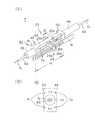
図1は本発明に係るPFO閉鎖デバイスを示す概略断面図、図2は同デバイスの一例を示す要部斜視図である。なお、図2では、紙面の都合上、手元操作部70のみを縮小した状態で記載している。 FIG. 1 is a schematic cross-sectional view showing a PFO closure device according to the present invention, and FIG. 2 is a perspective view of an essential part showing an example of the device. In FIG. 2, only the
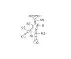
まず、本実施形態のPFO閉鎖デバイスについて概説する。このデバイスは、図1、2に示すように、基端側に設けられた手元操作部70と、手元操作部70に基端が取り付けられたガイディングカテーテル31と、ガイディングカテーテル31内に設けられたカテーテル30と、カテーテル30の先端部分に設けられ、卵円孔弁M2及び心房中隔M1を挟持する挟圧手段Kと、挟圧手段Kにより挟持した部分の生体組織M(M1,M2の総称)を融着乃至接合させるエネルギを供給するエネルギ供給手段20と、挟圧手段Kによる手技を安定かつ正確に行なうための位置決め保持手段60とを有している。なお、以下の説明において、デバイスの手元操作部側を「基端側」、挟圧手段K側を「先端側」と称す。 First, the PFO closure device of this embodiment will be outlined. As shown in FIGS. 1 and 2, the device includes a
このデバイスの使用を概説すれば、まず、ガイディングカテーテル31を、例えば、大腿静脈Jから挿入する。このガイディングカテーテル31内にカテーテル30の先端に設けられた挟圧手段Kをカテーテル30内に収納した状態で挿入する。先端が手技を行なう心臓の部位まで到達すれば、卵円孔の欠損O(以下、単に卵円孔Oと称することもある)が生じている心臓の心房中隔M1と卵円孔弁M2の組織を挟持する。この挟持状態で挟圧手段Kに電気エネルギを供給し、両組織を加熱融着し、欠損Oを閉鎖する。なお、図中、「L」は左心房、「R」は右心房を示す。 To outline the use of this device, first the guiding
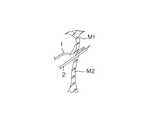
さらに詳述する。挟圧手段Kは、図2に示すように、心房中隔M1の一側面に直接接触する挟持部材1(第2挟持部材)と、卵円孔弁M2に穿刺する穿刺部2(第1挟持部材)とから構成されている。挟持部材1と穿刺部2は、いずれも電極部材として機能するものであり、基部がカテーテル30の先端に接合された先端チップ50に保持され、先端チップ50から突出されると、相互に対向する位置を取るようにルーメン内に位置規制されて収納されている。 Further details will be described. As shown in FIG. 2, the clamping means K includes a clamping member 1 (second clamping member) that directly contacts one side surface of the atrial septum M1, and a puncture unit 2 (first clamping) that punctures the foramen ovale valve M2. Member). The sandwiching
まず、挟持部材1は、全体的に扁平な板状で所定の幅Lを有する平板部1aと、基端部に接続された一対の線材部1bとから構成され、ルーメンL3,L4(図12参照)によりその平面位置が規制されており、また、U字状に形成された線材部1bの基端側に1本の操作コード7bが接続され、操作コード7bを軸方向に進退させることにより先端チップ50から突出したり、穿刺部2側に向って近接するように変位する。 First, the clamping
線材部1bは、折曲部1cと直状部1dを有し、直状部1dが先端チップ50のルーメンL3,L4(図11参照)に進退可能に挿通されているので、操作コード7bを牽引操作すれば、折曲部1cが先端チップ50のルーメンL3,L4の入口部分に入り込むとき、挟持部材1を穿刺部2に対し、平面位置が規制された状態で近接離間するように変位させることができ、細いカテーテル30の先端部であっても両電極部材による生体組織Mの挟持を容易にかつ円滑に行うことができる。 The
挟持部材1は、平板部1aの材質としては、SUS材であってもよいが、電極としての機能を果たし、生体に悪影響を及ぼさないもの、例えば、金、銀、白金、タングステン、パラジウムまたはこれらを含む合金や、Ni-Ti合金、チタン合金等を使用することが好ましい。 The sandwiching
穿刺部2は、先端チップ50に形成されたルーメンL1,L2(図11参照)によりその平面位置が規制された状態で進退可能に保持されており、また、U字状に形成された基端側に接続されている操作コード7cを操作することにより先端部が先端チップ50より出没し得るようになっている。 The
穿刺部2は、図2に示すように、軸直角断面が円形の、先端が鋭利に尖った極めて細い2本の針部材が相互に離間し、かつ、突出されると先端が拡開するように弾性が付与された一対の針部材である。このような穿刺部2により卵円孔弁M2を穿刺すれば、様々な形態の卵円孔弁や心房中隔であっても、針部材(電極部材)を卵円孔弁M2に位置決めすることができ、生体組織Mの挟持操作が容易になる。なお、先端が拡開するよう構成すれば、広範囲の卵円孔弁M2を融着させることができることになり、手技の容易化、迅速化、確実化に寄与する。 As shown in FIG. 2, the
穿刺部2は、針部材として機能するものであればどのようなものであってもよく、中実の針部材のみでなく、中空の円環状のものであってもよい。針部材の外径としては、0.1mm〜2mmのものが好ましい。材質としては、SUSが使用されるが、生体に悪影響を及ぼさないもの、例えば、金、銀、白金、タングステン、パラジウム、チタンまたはこれらを含む合金、Ni−Ti合金等を使用することもできる。本実施形態では、2本の針部材を使用しているが、さらに多数であってもよい。 The
挟持部材1や穿刺部2をカテーテル30から出没させる操作コード7b、7cとしては、細い線状の部材であり、挟圧手段Kをカテーテル30内で進退させることができ、電気導通性があれば、どのようなものであってもよい。例えば、ステンレス、Ni-Ti、チタンなどのワイヤーを使用することが好ましい。 As the
各操作コード7b、7cは、カテーテル30内を挿通し、後述の手元操作部70のソケット部材27、これに嵌合されるカプラー87、導線d(d1、d2の総称)及び制御部22と電気的に接続され、電気エネルギ供給手段20からの電気エネルギが供給されるようになっている。 The
挟圧手段Kでは、穿刺部2も挟持部材1もそれぞれ独立にカテーテル30内で軸線方向に移動可能となっている。このように穿刺部2及び挟持部材1を操作コード7b,7cを用いて相互に独立移動可能とすれば、穿刺部2では、任意の位置で穿刺でき、生体組織Mの状況に応じての手技が極めて容易で円滑になり、挟持部材1では、穿刺された状態の卵円孔弁M2に対し心房中膜M1を押しつける移動乃至操作や、肉厚方向での生体組織Mの位置決めが容易となる。 In the pinching means K, both the
なお、先端チップ50は、図11に示すように、複数のルーメンL1〜L5を有しているが、これら各ルーメンL1〜L5をそれぞれカテーテルにより構成してもよい。 The
手元操作部70は、図2に示すように、全体的には術者が片手で把持し易い形状、つまり、外周面が滑らかな円弧状を呈する矩形箱状の本体部75と、本体部75に対し近接離間するように進退自在に設けられたスライド部100とを有し、本体部75の上面には穿刺部2を操作する操作部材P2(第1操作部材)の一部である針操作レバー78が設けられている。ここに、挟持部材1を操作する操作部材P1(第2操作部材)とは、スライド部100、作動バー81、端子24(第2端子)及び操作コード7cから構成されるものであり、穿刺部2を操作する操作部材P2とは、針操作レバー78、端子23(第1端子)及び操作コード7cから構成されるものである(図3参照)。 As shown in FIG. 2, the
本体部75は、図2に示すように、最中合せされる左右一対の本体ピース75a,75bからなり、内部には、後述する穿刺端子用のチャンバ47や挟持端子用のチャンバ48が区画形成され、また、主管63なども収容されている。 As shown in FIG. 2, the
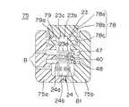
さらに詳述する。図3は図2の3−3線に沿う矢視端面図、図4(A)は仕切り部材の斜視図、図4(B)は図4(A)のB−B線に沿う断面図、図5は図2の5−5線に沿う矢視端面図、図6は図2の6−6線に沿う断面図である。なお、図4Aは、図2あるいは図3に示す取付状態より90度回転させた状態を示している。 Further details will be described. 3 is an end view taken along the line 3-3 in FIG. 2, FIG. 4A is a perspective view of the partition member, and FIG. 4B is a cross-sectional view taken along the line BB in FIG. 5 is an end view taken along line 5-5 in FIG. 2, and FIG. 6 is a cross-sectional view taken along line 6-6 in FIG. FIG. 4A shows a state rotated 90 degrees from the attached state shown in FIG. 2 or FIG.
図3に示すように、左側の本体ピース75aの内部には、比較的幅広の中央凹溝77が、中心軸線に沿い当該本体ピース75aの先端部より所定長Y1だけ形成され、中央凹溝77の右端部位はさらに幅広に形成され、ここに、穿刺用の端子23と挟持用の端子24との間で血液を介して通電が生じないようにする通電防止手段Tとしての仕切り部材40が嵌合されている。 As shown in FIG. 3, a relatively wide
仕切り部材40は、図4A及び図4Bに示すように、長手方向中心軸線に沿って開設された中央ルーメンLcと、中央ルーメンLcを中心として等角放射位置に中央ルーメンと平行に設けられた4つのサブルーメンLsとを備え、両端にフランジ部41,42を有するものである。仕切り部材40の製作に当っては、5ルーメンが形成された円柱状棒材を利用し、これの両側を削落することにより2つのサブルーメンLsを露出させ、ここに後述の端子摺動面43,44を形成している。なお、先端側のフランジ部41には、連結管45が軸線方向に突出され、ここにカテーテル30の基端側が連結される。基端側のフランジ部42には、ガイド管46が軸線方向に突出され、内部に主管63などが挿通されている。 As shown in FIGS. 4A and 4B, the
本実施形態の通電防止手段Tは、図6に示すように、本体部75を構成する左右一対の本体ピース75a,75bを左右から最中合せすることにより仕切り部材40を挟圧保持し、上方の穿刺端子用のチャンバ47(第1のチャンバ)と下方の挟持端子用のチャンバ48(第2のチャンバ)に仕切ることにより形成している。なお、両チャンバ47,48間のシール性を高めるために、仕切り部材40を、接着剤を用いて本体ピース75a,75bに接合している。ただし、このような方法のみでなく、例えば、本体ピース75a,75bと仕切り部材40とを凹凸嵌合させる方法、あるいは両者間にシール部材を介在させる方法などを用いてもよい。 As shown in FIG. 6, the energization preventing means T of the present embodiment holds the
このように仕切り部材40は、本体部75内中央に設けられ、主管63を支持する機能や、両チャンバ47,48間に血流の入り込みを防止する機能など、種々の機能を備えた重要な部材である。 As described above, the
本実施形態は、入り込んだ血流を外部に排出する排出口Bを、穿刺端子用のチャンバ47と挟持端子用のチャンバ48にそれぞれ形成している。排出口Bは、両チャンバ47,48に形成することが好ましいが、いずれか一方であってもよい。 In this embodiment, discharge ports B for discharging the blood flow that has entered are formed in the
このような排出口Bを形成すれば、仮に血流がチャンバ47,48内に流れ込んでも、これを容易に外部に排出し、通電防止をより確実なものにし、また、デバイスの内部を洗浄あるいはガス殺菌する場合も、洗浄液やガスの流れを円滑にし、極めて容易にかつ円滑に行うことができる。 If such a discharge port B is formed, even if blood flows into the
仕切り部材40の中央ルーメンLcは、図3に示すように、本体部75の内部に形成されている内部通路Qa及びスライド部100の内部通路Qbと共に、主通路Qの一部ともなっている。 As shown in FIG. 3, the central lumen Lc of the
本体部75の内部通路Qaには、主管63、主管63内に設けられた主操作ロッド7a、主管63の側部を伸延する操作コード7b,7cが設けられているが、主通路Q自体は、カテーテル30の先端から本体部75の内部通路Qa及びスライド部100の内部通路Qbを通り、スライド部100の後端まで貫通して形成されている。 The inner passage Qa of the
先端から後端まで貫通する主通路Qの形成により、例えば、デバイスを使用する前にプライミングを行う場合に、カテーテル30の先端から注入でき、プライミング作業が容易でかつ円滑にでき、空気混入のリスクが大幅に低減する。加えて、デバイス内部などの洗浄あるいはガス殺菌も容易となる。 By forming the main passage Q penetrating from the front end to the rear end, for example, when priming is performed before using the device, the injection can be performed from the front end of the
上方の穿刺端子用のチャンバ47では、仕切り部材40の上方側端子摺動面43に沿って穿刺用の端子23が内部をスライド移動し、下方の挟持端子用のチャンバ48では、仕切り部材40の下方側端子摺動面44に沿って挟持用の端子24が内部をスライド移動する。 In the upper
穿刺用の端子23は、図3、図4Aに示すように、上方側端子摺動面43に沿って移動する摺動片23aと、摺動片23aに一体に形成された突出片23bとからなり、摺動片23aには、操作コード7cの基端が半田などにより接合され、摺動片23bは、針操作レバー78に形成された嵌合溝23cに嵌合されている。 As shown in FIGS. 3 and 4A, the
針操作レバー78は、図6に示すように、頭部78a、首部78b、脚部78cを有し、首部78bが本体部75に形成されたスリット79(図2参照)を挿通し、頭部78aと脚部78cでレール79aを挟持している。したがって、穿刺用の端子23は、針操作レバー78をスリット79に沿って摺動すると、穿刺用操作コード7cを介して穿刺部2を進退させることができる。 As shown in FIG. 6, the
一方、挟持用の端子24は、図3、図4Aに示すように、端子摺動面44に沿って移動する摺動片24aと、摺動片24aに一体に形成された突出片24bとからなり、摺動片24aには挟持用操作コード7bの基端が半田などにより接合され、突出片24bは,一部にくびれ部が形成され、このくびれ部が作動バー81の軸線に沿って所定長Y2切除された作動溝部81aに嵌合されている。 On the other hand, as shown in FIGS. 3 and 4A, the clamping
作動バー81は、図3に示すように、本体部70からスライド部100にわたって設けられ、基端側がスライド部100に凹凸係合され、先端側が本体ピース75aに形成された溝部82に嵌合されている。したがって、挟持用の端子24は、スライド部100を後方にスライド移動すると、作動バー81がこれに伴って移動し、作動溝部81aの端部が突出片24bに当り、後退移動し、また、逆に、スライド部100を前方にスライド移動すると、作動溝部81aの反対側の端部が突出片24bに当り、突出片24bを前進移動することになる。これによって挟持部材1は、挟持用操作コード7bを介して穿刺部2に対し近接離間することになる。 As shown in FIG. 3, the operating
本体ケース75aの主通路Qには、図3に示すように、主管63が挿通されている。主管63は、このデバイスの、いわば中心軸的機能を発揮するものであるが、主管63の基端側は、断面T字状の管状ホルダー63aが固着され、ホルダー63aをスライド部100に形成されたT字状溝部に嵌合することにより取付けられている。したがって、主管63もスライド部100の前後進スライド動作に応じて両ケース75a,75b及び仕切り部材40にガイドされて摺動する。 As shown in FIG. 3, the
主管63を構成するものとしては、変形可能な弾性材料、例えば、ポリイミド樹脂、ポリウレタン、PET、ナイロン、フッ素樹脂、ポリプロピレンなどを使用することができる。 As the material constituting the
また、主管63内に設けられた主操作ロッド7aは、主管63内で軸線を中心に360度回転可能としている。主操作ロッド7aが360度回転可能であれば、卵円孔Oの近傍まで主操作ロッド7aの先端が挿入されたとき、主操作ロッド7aを回転的に位置変位させることができ、卵円孔Oの状態が種々変形していても、その形状状態如何に拘わらずデバイスの先端を卵円孔Oに挿通させることができ、手技を容易化するのみでなく、迅速に行うことができる。 Further, the
主操作ロッド7aとしては、細い中空線材で、比較的剛性を有するものであれば、どのようなものであってもよいが、例えば、ステンレス、Ni-Ti、チタンなどの細管を使用することが好ましい。 The
図5に示すように、前述した端子23,24の移動終端位置近傍には、接触部材25,26が設けられている。接触部材25,26は、導線d1、d2を介してエネルギ供給手段20のソケット部材27と接続されている。 As shown in FIG. 5, contact members 25 and 26 are provided in the vicinity of the movement end positions of the
接触部材25,26をさらに詳述する。図3と図5は、最中合わせされる本体ピース75aと75bの内部構成の理解を容易にするため、矢視方向を相違させて示し、天地の対応関係が逆の位置となっており、図3の下部と図5の上部、図3の上部と図5の下部が合体される部分である。また、図3と図5では、最中合わせされる本体ピース75aと75b内の各部材の対応関係が理解しやすいように対応して図示すると共に、各部材は断面せず、両本体ピース75aと75bの内端面のみを示している。 The contact members 25 and 26 will be further described in detail. 3 and FIG. 5 show the arrows in different directions in order to facilitate understanding of the internal configuration of the
図5において、接触部材25,26は、端子23,24と接触する当接部S1と、当接部S1から突出する脚部S2と、脚部S2の突出端が内部に収容される筒状カラーS3と、脚部S2を外方に向って弾発するバネS4とを有している。したがって、各当接部S1は、常時はバネS4により突出されるが、端子23,24により押されて後退する場合には、図示のように所定長の導通可能範囲X1内で移動することになる。このように所定長の導通可能範囲を有していると、人により卵円孔弁M2などの厚さや形状が相違することにより穿刺部2の穿刺状態あるいは挟持部材1の挟持状態が相違することにより、端子23,24の移動完了位置が区々となっても、接触部材25,26が端子23,24と確実に接触することになり、電気的に導通し、生体組織の融着あるいは壊死を確実に行うことができる。また、摺動的に電気的接触状態を形成する構成のものもあるが、このようなものに比べると、接触部材25,26と端子23,24との接触が確実になり、しかも故障も少なく、端子23,24のスライド操作も摩擦抵抗力が少なく軽いものとなる。 In FIG. 5, the contact members 25 and 26 have a cylindrical shape in which a contact portion S1 that contacts the
ただし、接触部材25,26と端子23,24の組がすべて弾性的接触状態である必要はなく、少なくとも一方のみであっても良く、他方は常時接触状態の構成としてもよい。 However, the set of the contact members 25 and 26 and the
なお、エネルギ供給手段20からの電流をオンオフ制御するスイッチSW(図1参照)が導線d1又はd2のいずれか一方に設けられているが、このスイッチSWは、手元操作しやすいスイッチであってもよいが、足元に設置するフットスイッチを使用することが好ましい。 Note that a switch SW (see FIG. 1) for controlling on / off of the current from the energy supply means 20 is provided on either one of the conductive wires d1 or d2. However, this switch SW may be a switch that is easy to operate at hand. Although it is good, it is preferable to use a foot switch installed at the foot.
図3に示すように、本体部75の左端部には、連結機構90が設けられている。連結機構90は、本体部75に対するYコネクタ72の脱着を容易にするためのもので、Yコネクタ72の基端部に設けられたフランジ部を、本体部75に形成された環状溝mに嵌合させると、摺動部材91がフランジ部の抜け止め機能を発揮し、Yコネクタ72が脱着可能となる。 As shown in FIG. 3, a connecting
なお、手元操作部70の先端には、造影剤などを注入することができるYコネクタ72を連結部材71により連結することが好ましいが、Yコネクタ72を使用しない場合には、本体部75にフランジ部を有するガイディングカテーテル31を直接連結することになる。なお、Yコネクタ72は、ガイディングカテーテル31の任意の位置に設けてもよい。
図7は連結機構の概略図である。連結機構90は、通孔94を有する平板である摺動部材91をバネ部材92により常時上方に弾発し、両本体ピース間に摺動可能に設置したものである。したがって、摺動部材91に設けられた押し片93をバネ部材92に抗して下方に向って押すと、通孔94が全開し、Yコネクタ72やガイディングカテーテル31などのフランジ部が挿通し得る大きさとなり、押し片93を放すとバネ部材92が上昇し、本体ピースと摺動部材91との間で通孔94の開口領域が狭められ、Yコネクタ72やガイディングカテーテル31などを本体部75に保持できる。 FIG. 7 is a schematic view of the coupling mechanism. The
図8は図3の8−8線に沿う概略断面図である。本体部75の両側方端部位には、図8に示すように、本体部75に対しスライド部100を進退させるための一対のガイドバー95が溝96内に設けられている。ガイドバー95の一端は、抜け止め用の大径部97が設けられ、スライド部100に形成された溝96の大径部に嵌合され、他端部は、本体部75内の溝96a内に摺動可能に挿入されている。 FIG. 8 is a schematic sectional view taken along line 8-8 in FIG. As shown in FIG. 8, a pair of guide bars 95 for advancing and retracting the
主管63内を挿通した主操作ロッド7aは、図8に示すように、スライド部100の中央に形成された内部通路Rbを通って外部まで伸延されているが、出口部分には、ロック−アンロック機構102が設けられている。 As shown in FIG. 8, the
図9はロック−アンロック機構を示す断面図、図10は図9の10−10線に沿う断面図である。
ロック−アンロック機構102は、主操作ロッド7aを把持するロッド把持バネ106と、ロッド把持バネ106による把持を解除する解除部材104と、本体部75に対しスライド部100の移動を規制する規制ロッド110とを有している。この機構102は、後述の保持部62が生体組織Mの保持を行う場合に、主操作ロッド7aのみを、スライド部100の軸方向外方へ移動させることによって行うことができ、しかも常時この保持状態を維持することができるように構成されているが、この保持状態も、解除部材104を押すことにより解除できるようになっている。9 is a cross-sectional view showing the lock-unlock mechanism, and FIG. 10 is a cross-sectional view taken along the line 10-10 in FIG.
The lock-
具体的には、スライド部100に開設された主操作ロッド7aを挿通する内部通路Qbの軸線に対し直交するスライド孔103内に設けられた解除部材104と、解除部材104の略中央に開設されたバネ保持孔105内に固定的に設置され、テニスのラケットのような特異な楕円形状を有し下端が相互に当接するように構成された、主操作ロッド7aを弾性的に把持するロッド把持バネ106と、解除部材104にスライド孔103からの突出習性を付与する補助バネ107と、この突出を阻止するストッパ部材108と、解除部材104と一体に形成され、本体部75aに対するスライド部100の移動を規制する規制ロッド110と、を有している。 Specifically, the
したがって、解除部材104は、常時は補助バネ107により外方に突出され、ロッド把持バネ106が、その形状の特異性から主操作ロッド7aを弾性的に把持するロック状態となり、解除部材104の頂端に設けられた押し片109を補助バネ107に抗して内方に押圧すると、ロッド把持バネ106によるロックが解除され、主操作ロッド7aがフリーな状態のアンロック状態となり、保持部62における主操作ロッド7aの湾曲状態が一挙に解除される。 Therefore, the
この結果、例えば、後述する保持部62が卵円孔弁M2を保持する場合、つまり主操作ロッド7aをスライド部100から引き出す方向に牽引する場合には、主操作ロッド7aは自由に引き出すことができ、引き出しを停止すると、後述の弾性線材66,67の弾性に抗して常時ロックするので、主操作ロッド7aを引き出すのみで卵円孔弁M2の保持ができ、この保持状態を維持できる。また、ロックを解除すれば、保持部62の弾性線材66,67の弾性により主操作ロッド7aの先端部分は自動的に直状になり、卵円孔弁M2の保持状態を簡単に解除できる。 As a result, for example, when the holding
しかも、前記ロックを解除すると、解除部材104と一体に動作する規制ロッド110も動作することになるが、規制ロッド110には、本体部75aの係合凹部111bと係合する係合突起111aが先端に設けられているので、係合突起111aと係合凹部111bとの係合も解除され、スライド部100は、本体部75aに対し可動状態となる。したがって、スライド部100を後退動作すれば、作動レバー81を介して挟持部材1を穿刺部2に対し近接作動させることができる。 Moreover, when the lock is released, the
このようにロックの解除と挟持部材1の作動を連動させることにより、長尺な主操作ロッド7aを左心房側から引き抜く際に誤って挟持操作1を作動させ、生体組織Mを損傷あるいは破断する事態を未然に防止できる。 By interlocking the unlocking and the operation of the clamping
エネルギ供給手段20は、挟圧手段Kに電気エネルギを供給するもので、公知のシステム構成のため詳述は避けるが、制御の容易性からすれば、直流電源や交流電源を問わず、電気的なものが好ましい。ただし、これのみでなく、挟圧手段Kにより挟持した卵円孔弁M2と心房中隔M1とを熱により溶融し、コラーゲンやエラスチンなどの接着因子で圧着させることが可能なエネルギを供給できるものであれば、どのようなものであってもよい。例えば、超音波、レーザー、マイクロ波あるいは高周波などを使用することもできる。 The energy supply means 20 supplies electric energy to the clamping means K, and will not be described in detail because of a known system configuration. However, from the viewpoint of ease of control, the electric power supply means 20 can be used regardless of whether it is a DC power supply or an AC power supply. Is preferable. However, not only this but also the one that can melt the oval valve M2 and the atrial septum M1 clamped by the clamping means K with heat and supply energy that can be crimped with an adhesive factor such as collagen or elastin. Anything may be used. For example, ultrasonic waves, lasers, microwaves, or high frequencies can be used.
また、電気エネルギ供給方式としては、右心房R側の穿刺部2あるいは挟持部材1と体表に設けられた対極板との間で通電するモノポーラ方式、右心房R側の挟持部材1と左心房L側の穿刺部2との間で通電するバイポーラ方式などを使用することができる。特に、穿刺部2と挟持部材1との間の生体組織Mのインピーダンスにより電流を制御するバイポーラ方式であれば、人により相違する卵円孔弁M2と心房中隔M1の組織の状態に応じて容易に対応することができ、安全性と手技の利便性が得られるという利点がある。 Further, as an electric energy supply method, a monopolar method in which current is supplied between the
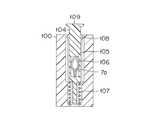
図11は図2の11−11線に沿う断面図である。先端チップ50は、図11に示すように、5つのルーメンL1〜L5が開設されており、第1及び第2のルーメンL1,L2と、第3及び第4のルーメンL3、L4には、前述のように穿刺部2と挟持部材1が挿通されている。また、中央の口径が最大の第5のルーメンL5には、主管63のほかに、主操作ロッド7aも挿通乃至収容され、主操作ロッド7aに位置決め保持手段60が設けられている。 11 is a cross-sectional view taken along line 11-11 in FIG. As shown in FIG. 11, the
位置決め保持手段60は、図2に示すように、概して、穿刺部2を卵円孔Oに対し位置決めする位置決め部61と、穿刺部2の穿刺方向に対し卵円孔弁M2を後退不能に保持する保持部62とを有し、常時はガイディングカテーテル31内に収納されているが、使用時には、図示のように主操作ロッド7a及び主管63を操作することによりガイディングカテーテル31から押し出される。 As shown in FIG. 2, the positioning and holding means 60 generally holds a
さらに詳述すれば、中央のルーメンL5には、主管63と、主管63内で軸方向に進退自在に設けられた主操作ロッド7aが設けられている。主管63は、主通路Q内を伸延するもので、中心軸的な機能を発揮し、またカテーテル30を補強するものでもあるが、さらに、位置決め保持手段60をカテーテル30内に引き込み回収するものでもある。主操作ロッド7aは、カテーテル30の先端から主管63内を通りスライド部100の内部通路Rbを通って、後端より突出されている。 More specifically, the central lumen L5 is provided with a
主管63の先端部には、主操作ロッド7aに設けられた位置決め保持手段60が連結されており、位置決め保持手段60は、位置決め部61と保持部62とから構成されている。 A positioning / holding means 60 provided on the
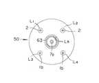
位置決め部61は、卵円孔Oに対し穿刺部2を位置決めするもので、図2に示すように、主操作ロッド7aの操作により拡開縮小作動される一対の第1弾性線材66から構成されている。第1弾性線材66の基端は、先端チップ50に形成されたガイド溝51にガイドされた後に、先端チップ50内で主管63の外面に取り付けられ、先端は、中間スリーブ体64に取り付けられている。 The positioning
このように第1弾性線材66の主管63と連結する基端側を、カテーテル30の先端部内に設けられた先端チップ50に形成されたガイド溝51で支持した状態で主管と連結すると、第1弾性線材66を長くすることができ、種々の欠損に対応して確実に位置決めできる位置決め部となる。 When the base end side of the first
位置決め部61は、主操作ロッド7aを主管63の先端より突出し、主操作ロッド7aを軸方向に進退する操作により、主管63に取り付けた基端を支点として第1弾性部材66を外方に変位させ、各第1弾性部材66が卵円孔Oの内縁を略等しい弾性力で押圧し、穿刺部2を卵円孔Oに対して調心する。つまり、両第1弾性部材66間に位置する穿刺部2を卵円孔Oの中央部に位置させる機能を発揮する。 The positioning
保持部62は、図2に示すように、主操作ロッド7aの先端部に設けられた当り部材68、先端スリーブ体65、及び、中間スリーブ体64と先端スリーブ体65とを連結する一対の第2弾性線材67を有し、当り部材68及び先端スリーブ体65により卵円孔弁M2を保持するものである。 As shown in FIG. 2, the holding
保持部62は、主操作ロッド7aを軸方向に進退操作することにより、主管63に取り付けた第1弾性部材66の基端を支点として、主操作ロッド7aの先端部を湾曲させる湾曲機構Wを有している。 The holding
湾曲機構Wは、保持部62を、穿刺部2が卵円孔弁M2を穿刺する方向に対向するように湾曲させ、卵円孔弁M2を保持する機能を発揮する。ここに、湾曲機構Wは、中間スリーブ体64、先端スリーブ体65、両スリーブ体64,65を連結する第2弾性線材67、当り部材68から構成されている。第2弾性線材67の基端は、中間スリーブ体64の先端に溶着され、先端側は、先端スリーブ体65に溶着されている。 The bending mechanism W exhibits a function of holding the oval hole valve M2 by bending the holding
ただし、保持部62の湾曲機構Wは、位置決め部61の第1弾性部材66が穿刺部2を卵円孔Oに対して調心して位置決めを行った後に、湾曲して卵円孔弁M2を保持するように構成する必要があるので、第1弾性部材66が第2弾性線材67に先んじて変形する必要がある。 However, the bending mechanism W of the holding
この構成としては、例えば、材質的に第2弾性線材67の方が第1弾性線材66よりも高剛性のものを使用する方法、第1弾性線材66の一部を予め屈曲変形するなどの易変形部を形成し、牽引力が作用すると易変形部の変形により第1弾性線材66が第2弾性線材67より先に湾曲させる方法なども使用できる。 As this configuration, for example, the second
第1及び第2の弾性線材66,67の具体例としては、外径が、0.1mm〜0.5mm程度で、ステンレス鋼、ニッケル−チタン、超弾性合金(例えば、Ni−Ti合金)などの金属ワイヤーを使用することが好ましい。また、金属ワイヤーに樹脂(軟性)チューブを被覆することで組織の傷付きを防止させてもよい。 Specific examples of the first and second
本体部75に対しスライド部100を進退させると、スライド部100に固着されている主管63をカテーテル30の中央のルーメンL5内に引き込むことができ、これに伴って位置決め保持手段60全体をカテーテル30内に回収できる。 When the
本実施形態のガイディングカテーテル31は、卵円孔弁M2と心房中隔M1との間の卵円孔Oに容易に向うことができるように、先端が円弧状に緩やかに湾曲してもよい。卵円孔弁M2と心房中隔M1とは、人により相違するので、ガイディングカテーテル31の先端を湾曲させると、ガイディングカテーテル31自体を回動するのみで卵円孔Oに向けることでき、直状の場合よりも手技の安全性と利便性が向上する。 The guiding
次に、本実施形態の作用を説明する。 Next, the operation of this embodiment will be described.
図12は主操作ロッドを卵円孔に挿入する断面概略図、図13は卵円孔弁を保持し穿刺部を穿刺した状態の断面概略図、図14は穿刺部と挟持部材とにより卵円孔弁及び心房中隔を挟持した断面概略図、図15(A)〜(D)はPFO閉鎖デバイスの先端部の操作状態を示す概略図である。なお、図15(A)〜(D)において、第2弾性線材66の形状及び位置は、挟持部材1や穿刺部2と略面一の状態であるが、理解を容易にするために、図示の位置を90度変位した状態で示しており、実際の変形状態とは相違する。 12 is a schematic cross-sectional view of the main operating rod inserted into the foramen ovale, FIG. 13 is a schematic cross-sectional view of the state where the puncture part is punctured while holding the oval hole valve, and FIG. 14 is an oval by the puncture part and the holding member. Cross-sectional schematic diagrams sandwiching the foramen valve and the atrial septum, FIGS. 15A to 15D are schematic diagrams showing the operating state of the distal end portion of the PFO closure device. In FIGS. 15A to 15D, the shape and position of the second
まず、術者は、ロック−アンロック機構102の押し片109をスライド部100の内方に押圧すると、規制ロッド110の係合突起111aと本体部75の係合凹部111bとの係合が外れるので、スライド部100は本体部75に対し可動状態になる。 First, when the surgeon presses the
スライド部100を本体部75に対し後退させると共に、針操作レバー78も後退させると、挟持部材1や穿刺部2などがカテーテル30内に収納された状態となる。ただし、カテーテル30の先端部は、ガイディングカテーテル31の先端より少し突出した状態とする。この状態で、ガイドワイヤーをガイドとしてガイディングカテーテル31の先端を生体の所定位置から挿入し、大腿静脈Jを通り右心房Rまで到達させる。なお、ガイディングカテーテル31のみを生体に挿入し、後にこれをガイドにカテーテル30を挿入してもよい。 When the
カテーテル30の先端が右心房Rに到達すると、スライド部100を少し前進させ、主管63を前進移動させると共に、ロック−アンロック機構102の押し片109を押圧し、主操作ロッド7aをフリーな状態にして主管63の先端から主操作ロッド7aを押し出し、卵円孔弁M2と心房中隔M1との間の卵円孔Oに向わせる。なお、ガイディングカテーテル31の先端は湾曲しているので、カテーテル30もガイディングカテーテル31にガイドされて湾曲し、カテーテル30を介して湾曲した主操作ロッド7aを比較的容易に卵円孔Oに向わせることができる。 When the distal end of the
次に、主操作ロッド7aを前進させ、図15(A)に示すように、主操作ロッド7aの先端を先端スリーブ体65から突出し、左心房L内に挿入する。この突出状態は、当り部材68などにX線不透過マーカーを設けていると、X線画像により外部から視認することができるが、この突出により主操作ロッド7aの先端が左心房Lの内壁などに当ると、視認が困難な場合であっても、感覚的に主操作ロッド7aの位置を確認できる。本実施形態では、主操作ロッド7aを360度回転可能としているので、図12に示すように、主操作ロッド7aを回転しながら前進でき、卵円孔Oに容易に挿通させることができる。 Next, the
主操作ロッド7aの先端位置の確認後、図15(B)に示すように、主操作ロッド7a先端の当り部材68が先端スリーブ体65に当接するまで主操作ロッド7aを後退させる(後退量は図15Bの「δ1」)。ロック−アンロック機構102は、押し片109を押圧しない限り主操作ロッド7aが弾性線材66,67の弾性に抗して前方移動しないようにロックしているので、主操作ロッド7aの後退は、後退を停止した時点でロックされる。そして、本体部75を操作し、第2弾性線材67、挟持部材1及び穿刺部2を卵円孔弁M2の近傍に位置させ、保持部62全体を左心房L側に挿入する。 After confirming the tip position of the
主操作ロッド7aをさらに後退させると(後退量は図15Cの「δ2」)、この後退させる操作力が、主操作ロッド7aにより、当り部材68、先端スリーブ体65、第2弾性線材67及び中間スリーブ体64を介して、基端が主管63に取り付けられた第1弾性線材66に伝達され、第1弾性線材66を、図15(C)に示すように、径方向外方に向って円弧状に突出変形させる。ただし、この時点では第2弾性線材67は変形していない。 When the
この結果、第1弾性線材66は、卵円孔Oの口縁部分を押し広げつつ変形することになるので、第1弾性線材66の直近に設けられている穿刺部2を卵円孔Oに対して調心し、穿刺部2を卵円孔Oの中心に位置させる。 As a result, the first
さらに主操作ロッド7aを後退操作し、図15(D)に示すように、中間スリーブ体64の後端が主管63の先端に当接すると、第1弾性線材66はあまり変形せず、先端側の第2弾性線材67が、操作力により径方向外方に向って円弧状に突出変形する。この結果、図13に示すように、左心房L内において、当り部材68と先端スリーブ体65が穿刺部2に近付くように湾曲するので、当り部材68と先端スリーブ体65は、卵円孔弁M2の左心房側の面に当接し、これを保持することになる。 When the
ロック−アンロック機構102は、ロッド把持バネ106により主操作ロッド7aを常時前方移動しないようにロックしているので、主操作ロッド7aの長手方向に位置がロックされている。したがって、術者が主操作ロッド7aから手を放しても保持状態は維持され、卵円孔弁M2の保持が緩むことはなく、術者は、右手のみで針操作レバー78を前進させることができる。 Since the lock-
針操作レバー78を前進させると、端子23,操作コード7cを介して穿刺部2をカテーテル30の先端から突出し、卵円孔弁M2の所定位置に穿刺部2を穿刺する。卵円孔弁M2の保持の緩みによる穿刺不能という事態が生じる虞はない。 When the
穿刺部2の位置は、位置決め保持部62により定められるので、ズレる虞はなく、また一旦穿刺部2を穿刺すると、穿刺部2の位置は、卵円孔弁M2との関係では固定的な位置となる。したがって、術者は、穿刺操作が極めて容易になる。 Since the position of the
この穿刺により手元操作部70では、端子23が接触部材25に弾性的に接触した状態になる。 By this puncturing, the terminal 23 is brought into a state of elastically contacting the contact member 25 in the
穿刺が完了すると、スライド部100を本体部75に対しさらに前進させる。これにより作動レバー81が前進し、端子23及び操作コード7bを介して挟持部材1の平板部1aがカテーテル30の先端から突出する。そして、平板部1aが心房中隔M1に対向する位置になると、スライド部100を本体部75より多少後退させる。これにより作動レバー81も後退し、端子23及び操作コード7bを介して平板部1aが後退され、線材部1bの曲げが先端チップ50のルーメン内に入るときの影響を受け、平板部1aは穿刺部2に近付くように変位する。この変位により平板部1aは、心房中隔M1を卵円孔弁M2に向って押圧し、心房中隔M1と卵円孔弁M2が肉厚方向、つまり操作状態では前後方向の位置が固定され、図14に示すように、挟持部材1と穿刺部2の間に心房中隔M1と卵円孔弁M2が存在している状態となる。 When the puncturing is completed, the
この段階で、ロック−アンロック機構102の押し片109を押し、ロッド把持バネ106による主操作ロッド7aのロックを解除すれば、主操作ロッド7aと当り部材68による第1弾性線材66と第2弾性線材67の加圧がなくなり、第1弾性線材66と第2弾性線材67が自らの弾性力により直状に伸び、図13(B)に示す状態になる。この状態で、スライド部100を後退操作すると、主管63を介して位置決め保持手段60全体がカテーテル30のルーメンL5内に回収される。 At this stage, if the
このスライド部100の後退は、操作コード7bを介して挟持部材1の折曲部1cが先端チップ50の端部により穿刺部2側に近づくように変形させることになるので、図14に示すように、心房中隔M1と卵円孔弁M2は、挟持部材1と穿刺部2との間で強固に挟持されることになる。一方、手元操作部70では、主管63に取り付けられている端子24も後退し接触部材26に接触することになる。 This retraction of the
つまり、この段階でのスライド部100の後退は、生体組織Mの挟持と、端子24と接触部材26との接触状態を一挙に行うことになる。しかも、端子23と接触部材25とは先に接触状態となっているので、端子24と接触部材26との接触により挟持部材1と穿刺部2に電気エネルギを供給可能な状態となる。 In other words, the retraction of the
したがって、術者がスイッチSWを作動させると、制御部22により制御された所定の電気エネルギが操作コード7b,7cを介して挟持部材1と穿刺部2に供給され、心房中隔M1と卵円孔弁M2が加熱される。 Therefore, when the operator operates the switch SW, the predetermined electrical energy controlled by the
電気エネルギの制御部22は、出力を低く制御することにより血栓の付着が生じにくくしているので、挟持部材1と穿刺部2の一部が血液中に露出していても、挟持部材1や穿刺部2に血栓の付着を防止することは可能である。ただし、挟持部材1や穿刺部2の血液露出面に熱伝導を抑えるコーティングをすれば、血栓の付着は一層確実に防止されることになり、好ましい。 Since the electrical
融着温度を維持しつつ加熱を継続すると、心房中隔M1と卵円孔弁M2の組織が溶融し、コラーゲンやエラスチンなどの接着因子により相互に融着される。 When heating is continued while maintaining the fusion temperature, the tissues of the atrial septum M1 and the foramen ovale valve M2 are melted and fused to each other by an adhesion factor such as collagen or elastin.
この治療中に、血液がカテーテル30内、あるいはカテーテル30とガイディングカテーテル31との間を通り手元操作部70の内部にまで流れ込み、これが両端子23,24間に至ると、血流を介して通電する虞がある。 During this treatment, blood flows into the
しかし、本実施形態では、穿刺用の端子23と挟持用の端子24が作動するチャンバ47,48が仕切り部材40により仕切られ、血液が両端子23,24間に入り込まないようにしているので、血流を介しての通電が防止される。したがって、術者は、生体組織Mを穿刺部と挟持部材により挟持するという手技に専念でき、手技も円滑かつ確実に行うことができる。 However, in the present embodiment, the
融着が完了すると、電気エネルギの供給を停止し、スライダ部100を後退し、穿刺部2を収容する。そして、連結機構90の93を押し、ガイディングカテーテル31と本体部75との連結を解き、本体部75を生体から離すように後退させると、ガイディングカテーテル31をガイドとしてデバイスが引き出される。この後、ガイディングカテーテル31を生体から抜去すると、手技は完了する。なお、手技の完了後、穿刺部2の抜去により卵円孔弁M2には極めて小さな穴が残るが、後に治癒され、血栓の発生などの悪影響が生じることはない。 When the fusion is completed, the supply of electric energy is stopped, the
本発明は、上述した実施形態のみに限定されるものではなく、本発明の技術的思想内において当業者により種々変更が可能である。例えば、前述の通電防止手段は、仕切り部材40により穿刺用の端子23と挟持用の端子24が作動するチャンバ47,48を仕切るものであるが、これのみでなく、カテーテル30の基端部を連結する手元操作部70に止血弁V(図8参照)を設け、カテーテル30を通り手元操作部70へ流入する血液を阻止するようにしてもよい。このようにすれば、血流がカテーテル30を通って手元操作部70にまで流下しても、止血弁Vがこれを阻止し、血流による通電が防止でき、しかも、止血弁Vの設置のみであるため、構成が簡単で、コスト的に有利なデバイスとなる。 The present invention is not limited to the above-described embodiments, and various modifications can be made by those skilled in the art within the technical idea of the present invention. For example, the energization preventing means described above partitions the
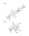
実施形態における位置決め保持手段60は、中間スリーブ体64を有するものであるが、これのみに限定されるものではない。例えば、図16は位置決め保持手段の他の例を示す概略図であるが、図16(A)のように、本実施形態において設けられる中間スリーブ体64は設けずに、先端スリーブ体65と主管63の間に、第1弾性線材66および第2弾性線材67を設けてもよい。この形態においては、主操作ロッド7aを後退させると、図16(B)のように、第1弾性線材66が径方向外方に向って円弧状に突出変形しつつ、第2弾性線材67が円弧状に屈曲変形する。すなわち、第1弾性線材66による穿刺部2の卵円孔Oの中心への位置決めと、第2弾性線材67によって屈曲した当り部材68と先端スリーブ体65による卵円孔弁M2の保持を、主操作ロッド7aの後退による1動作で同時に行うこととなる。 The positioning / holding means 60 in the embodiment includes the
実施形態では、PFOの欠損を閉鎖する治療に使用されるものについて説明したが、本発明は、これのみに限定されるものではなく、左心耳閉鎖デバイス(Left Atrial Appendage)といった通路状の欠損を閉鎖する場合や、あるいは所定の部位の生体組織Mを熱的に壊死させる場合にも使用可能である。 Although the embodiment has been described with respect to a treatment used to close a PFO defect, the present invention is not limited to this, and a passage-like defect such as a left atrial appendage closure device (Left Atrial Appendage) is used. It can also be used when closing or when the living tissue M at a predetermined site is thermally necrotized.
前記実施形態のPFO閉鎖デバイスは、単にカテーテル内に収納して操作コードにより挟圧手段を操作しているが、これのみでなく、例えば、いわゆるバルーンを有するカテーテルと組み合わせ、所定位置まで搬送することも可能である。 The PFO closure device of the above embodiment is simply housed in a catheter and the clamping means is operated by an operation cord. However, not only this but also a combination with a catheter having a so-called balloon, for example, can be transported to a predetermined position. Is also possible.
本発明は、生体組織の欠損部を、簡単かつ安全に閉鎖可能なデバイスとして利用できる。 INDUSTRIAL APPLICATION This invention can be utilized as a device which can close the defect | deletion part of a biological tissue simply and safely.
1…挟持部材、
2…穿刺部、
7a…主操作ロッド、
7b…挟持用操作コード、
7c…穿刺用操作コード、
20…電気エネルギ供給手段、
23,24…端子、
25,26…接触部材、
30…カテーテル、
40…仕切り部材(仕切り手段)、
47…穿刺端子用のチャンバ、
48…挟持端子用のチャンバ、
61…位置決め部、
62…保持部、
63…主管、
70…手元操作部、
75…本体部、
75a,75b…本体ピース、
81…作動バー、
100…スライド部、
102…ロック−アンロック機構、
B…排出口、
K…挟圧手段、
Lc…中央ルーメン、
Ls…サブルーメン、
M…生体組織、
M1…心房中隔、
M2…卵円孔弁、
O…卵円孔、
P1…挟持用操作部材、
P2…穿刺用操作部材、
Q…主通路、
Qb…内部通路、
T…通電防止手段,
W…湾曲機構。1 ... clamping member,
2 ... Puncture part,
7a ... main operation rod,
7b: Operation code for clamping,
7c: Puncture operation code,
20: Electric energy supply means,
23, 24 ... terminals,
25, 26 ... contact members,
30 ... catheter,
40 ... partition member (partition means),
47. Chamber for puncture terminal,
48 ... Chamber for holding terminals,
61 ... positioning part,
62 ... holding part,
63 ...
70: Hand control unit,
75 ... Body part,
75a, 75b ... main body piece,
81. Actuating bar,
100 ... slide part,
102: lock-unlock mechanism,
B ... discharge port,
K ... clamping means,
Lc ... Central lumen,
Ls ... Sublumen,
M ... living tissue,
M1 ... Atrial septum,
M2 ... foramen valve,
O ... foramen,
P1: clamping operation member,
P2 ... Puncture operation member,
Q ... main passage,
Qb ... internal passage,
T ... Prevention of electricity
W: Bending mechanism.
Claims (9)
Translated fromJapanese当該挟圧手段が内部に収納され、使用時に先端から突出されるカテーテルと、
当該カテーテルの基端部に設けられ前記挟圧手段を操作する手元操作部と、
前記挟圧手段により挟持した前記生体組織を融着あるいは壊死させ前記欠損を閉鎖する電気エネルギを前記第1挟持部材及び前記第2挟持部材に供給するエネルギ供給手段と、
を有する生体組織閉鎖デバイスであって、
前記手元操作部は、
本体部と、
当該本体部に設けられ、前記第1挟持部材を操作する第1操作部材と、
前記本体部に設けられ、前記第2挟持部材を操作する第2操作部材と、
当該第1操作部材の操作により、前記エネルギ供給手段に接続された給電側の接触部材と接する、前記第1操作部材に設けられた第1端子と、
前記第2操作部材の操作により、前記エネルギ供給手段に接続された給電側の他の接触部材と接する、前記第2操作部材に設けられた第2端子と、を備え、
前記第1端子側と前記第2端子側が血液を介して通電されないように構成した通電防止手段を有し、
前記通電防止手段は、前記本体部に、
前記第1端子が内部をスライド移動する第1のチャンバと、
前記第2端子が内部をスライド移動する第2のチャンバと、を形成し、
前記カテーテルを通って流入する血液が前記両チャンバ間で相互に流通しないように前記両チャンバ間を仕切る仕切り手段により構成したことを特徴とする生体組織閉鎖デバイス。A clamping means having a first clamping member and a second clamping member for clamping the biological tissue around the defect existing in the biological tissue;
A catheter that is housed in the pinching means and protrudes from the tip during use;
A hand operating part that is provided at the proximal end of the catheter and operates the clamping means;
Energy supply means for supplying electric energy for fusing or necrosing the living tissue sandwiched by the sandwiching means and closing the defect tothe first sandwiching member andthe second sandwiching member;
A biological tissue closure device comprising:
The hand operating unit is
The main body,
A first operating member that is provided in the main body and operates the first clamping member;
A second operating member provided on the main body and operating the second clamping member;
A first terminal provided on the first operating member that is in contact with a contact member on a power feeding side connected to the energy supply means by operating the first operating member;
A second terminal provided on the second operation member that comes into contact with another contact member on the power feeding side connected to the energy supply means by operation of the second operation member;
Wherein the first terminal-side second terminal sidehave a conduction preventing means configured not energized via theblood,
The energization preventing means is provided on the main body,
A first chamber in which the first terminal slides;
Forming a second chamber in which the second terminal slides.
A biological tissue closing devicecomprising partition means for partitioning the chambers so that blood flowing through the catheter does not flow between the chambers .
前記仕切り部材は、前記本体部の長手方向に沿って伸延する中央ルーメンと、当該中央ルーメンを中心として等角放射位置に前記中央ルーメンと平行に設けられた4つのサブルーメンとを備え、前記カテーテルの基端を前記仕切り部材の中央ルーメンと連通連結すると共に、前記手元操作部内に前記中央ルーメンと連通する内部通路を後端部まで形成することにより、前記カテーテルの先端から前記手元操作部の後端部まで連通する主通路の一部としたことを特徴とする請求項1に記載の生体組織閉鎖デバイス。The partition means is constituted by a pair of body pieces in which the body portions are aligned together, and a partition member provided between the chambers formed on one or both of the body pieces is sandwiched between the body pieces. Configured by
The partition member includes a central lumen extending along a longitudinal direction of the main body portion, and four sublumens provided in parallel with the central lumen at an equiangular radial position around the central lumen. The proximal end of the catheter is connected in communication with the central lumen of the partition member, and an internal passage communicating with the central lumen is formed in the proximal operation portion from the distal end to the rear end of the proximal operation portion. The living tissue closing device according to claim 1, wherein the biological tissue closing device isa part of a main passage communicating to an end .
前記手元操作部は、
前記本体部に設けられ、前記穿刺部を操作する穿刺用操作部材と、
前記本体部に設けられ、前記挟持部材を操作する挟持用操作部材と、
当該穿刺用操作部材の操作により、前記エネルギ供給手段に接続された給電側の接触部材と接する、前記穿刺用操作部材に設けられた穿刺用の端子と、
前記挟持用操作部材の操作により、前記エネルギ供給手段に接続された給電側の他の接触部材と接する、前記挟持用操作部材に設けられた挟持用の端子と、を有することを特徴とする請求項1に記載の生体組織閉鎖デバイス。The pinching means punctures a living tissue in the vicinity of a defect existing in the living tissue, the puncturing portion forming the first clamping member, and the second puncturing portion cooperates with the living tissue. A sandwiching member forming a sandwiching member,
The hand operating unit is
A puncture operating member provided on the main body for operating the puncture section;
An operation member for clamping provided in the main body and operating the clamping member;
A puncture terminal provided on the puncture operation member that comes into contact with a power supply side contact member connected to the energy supply means by operating the puncture operation member;
Claims by operation of the clamping operation member in contact with the other contact member of the connected power supply side to the energy supply means, characterized byhaving a, a terminal for clamping provided in the pinching operation memberItem 2. The biological tissue closure device according toItem 1 .
当該保持部は、前記主通路の前記カテーテル内を挿通し端部が前記本体部に固定された主管と、当該主管を挿通し基端部が前記本体部から突出された主操作ロッドと、該主操作ロッドを軸方向に進退操作することにより該主操作ロッドの先端部を湾曲させ前記生体組織を後退不能に保持する湾曲機構と、前記主操作ロッドを常時は前進不能にロックして前記湾曲機構の湾曲状態を維持し、アンロックすることにより前記湾曲状態を解除するロック−アンロック機構と、を有し、
当該ロック−アンロック機構を前記スライド部に設けたことを特徴とする請求項7に記載の生体組織閉鎖デバイス。The biological tissue closing device has a holding part that holds the biological tissue in a non-retractable manner with respect to the puncturing direction of the puncturing part,
The holding portion includes a main tube having an end portion inserted through the catheter of the main passage and fixed to the main body portion, a main operation rod having a base end portion which is inserted through the main tube and protruded from the main body portion, A bending mechanism for bending the main operating rod in the axial direction to bend the tip of the main operating rod to hold the living tissue so that it cannot be retracted, and to lock the main operating rod so that the main operating rod cannot always move forward. A lock-unlock mechanism that maintains the bending state of the mechanism and releases the bending state by unlocking the mechanism,
The biological tissue closing device according toclaim 7 ,wherein the lock-unlock mechanism is provided in the slide portion .
当該位置決め部は、
前記主通路の前記カテーテル内を挿通し端部が前記手元操作部に固定された主管と、
当該主管内に挿通され端部が前記本体部から突出された主操作ロッドと、
該主操作ロッドの先端に取り付けられた先端スリーブ体と前記主管との間に両端が連結され、前記主操作ロッドの後方への牽引により放射方向外方に拡開される少なくとも一対の第1弾性線材と、を有し、
前記第1弾性線材の前記主管と連結する基端側を、前記カテーテルの先端部内に設けられた先端チップに形成されたガイド溝で支持した状態で前記主管と連結することを特徴とする請求項7に記載の生体組織閉鎖デバイス。The biological tissue closing device hasa positioning part for positioning the puncturepart with respect to the defect,
The positioning part is
A main tube having an end inserted through the catheter of the main passage and fixed to the hand operation unit;
A main operation rod inserted into the main pipe and having an end protruding from the main body;
At least a pair of first elastic members whose both ends are connected between the tip sleeve body attached to the tip of the main operation rod and the main pipe and are expanded radially outward by pulling the main operation rod rearward. A wire, and
Claims, characterized inthat the proximal end side connecting to the main pipe of the first elastic wire, connecting the main and in a state of being supported by the distal tip to form a guide groove provided in the distal end portion of said catheter 8. The biological tissue closing device according to7 .
Priority Applications (1)
| Application Number | Priority Date | Filing Date | Title |
|---|---|---|---|
| JP2008255696AJP5311632B2 (en) | 2008-09-30 | 2008-09-30 | Biological tissue closure device |
Applications Claiming Priority (1)
| Application Number | Priority Date | Filing Date | Title |
|---|---|---|---|
| JP2008255696AJP5311632B2 (en) | 2008-09-30 | 2008-09-30 | Biological tissue closure device |
Publications (2)
| Publication Number | Publication Date |
|---|---|
| JP2010082276A JP2010082276A (en) | 2010-04-15 |
| JP5311632B2true JP5311632B2 (en) | 2013-10-09 |
Family
ID=42246813
Family Applications (1)
| Application Number | Title | Priority Date | Filing Date |
|---|---|---|---|
| JP2008255696AActiveJP5311632B2 (en) | 2008-09-30 | 2008-09-30 | Biological tissue closure device |
Country Status (1)
| Country | Link |
|---|---|
| JP (1) | JP5311632B2 (en) |
Families Citing this family (2)
| Publication number | Priority date | Publication date | Assignee | Title |
|---|---|---|---|---|
| JP7410198B2 (en)* | 2022-02-28 | 2024-01-09 | 日本ライフライン株式会社 | Balloon electrode catheter |
| JP7410199B2 (en)* | 2022-02-28 | 2024-01-09 | 日本ライフライン株式会社 | Balloon electrode catheter |
Family Cites Families (4)
| Publication number | Priority date | Publication date | Assignee | Title |
|---|---|---|---|---|
| JPH11226025A (en)* | 1998-02-17 | 1999-08-24 | Olympus Optical Co Ltd | Piercing device |
| US7186251B2 (en)* | 2003-03-27 | 2007-03-06 | Cierra, Inc. | Energy based devices and methods for treatment of patent foramen ovale |
| US8109274B2 (en)* | 2005-04-11 | 2012-02-07 | Terumo Kabushiki Kaisha | Methods and electrode apparatus to achieve a closure of a layered tissue defect |
| EP1986559B1 (en)* | 2006-02-24 | 2012-03-28 | Terumo Kabushiki Kaisha | Pfo closing device |
- 2008
- 2008-09-30JPJP2008255696Apatent/JP5311632B2/enactiveActive
Also Published As
| Publication number | Publication date |
|---|---|
| JP2010082276A (en) | 2010-04-15 |
Similar Documents
| Publication | Publication Date | Title |
|---|---|---|
| EP2184024B1 (en) | Medical device | |
| JP5763619B2 (en) | Medical device | |
| EP2184019B1 (en) | Device for opening/closing biological tissue | |
| US8920418B2 (en) | PFO closing device | |
| JP5311632B2 (en) | Biological tissue closure device | |
| US10531911B2 (en) | Medical device | |
| JP2010220883A (en) | Medical device | |
| JP5451132B2 (en) | Medical device | |
| JP5289808B2 (en) | Biological tissue closure device | |
| JP5311631B2 (en) | Biological tissue closure device | |
| JP5059670B2 (en) | Biological tissue closure device | |
| JP5873475B2 (en) | PFO closure device | |
| JP2009050590A (en) | Pfo closing device | |
| JP2009050592A (en) | Pfo closing device | |
| JP2009050593A (en) | Pfo closing device | |
| JP2009050585A (en) | Pfo closing device | |
| WO2014010041A1 (en) | Medical device | |
| WO2014049676A1 (en) | Medical device | |
| JP2009050586A (en) | Pfo closing device | |
| JP5290022B2 (en) | Medical device | |
| JP2012200528A (en) | Medical device | |
| JP2009050587A (en) | Pfo closing device | |
| JP2015097549A (en) | Medical device, and manufacturing method of the same | |
| JP2012200280A (en) | Medical device | |
| JP2012200529A (en) | Medical device |
Legal Events
| Date | Code | Title | Description |
|---|---|---|---|
| A621 | Written request for application examination | Free format text:JAPANESE INTERMEDIATE CODE: A621 Effective date:20110613 | |
| A977 | Report on retrieval | Free format text:JAPANESE INTERMEDIATE CODE: A971007 Effective date:20121228 | |
| A131 | Notification of reasons for refusal | Free format text:JAPANESE INTERMEDIATE CODE: A131 Effective date:20130115 | |
| A521 | Request for written amendment filed | Free format text:JAPANESE INTERMEDIATE CODE: A523 Effective date:20130315 | |
| TRDD | Decision of grant or rejection written | ||
| A01 | Written decision to grant a patent or to grant a registration (utility model) | Free format text:JAPANESE INTERMEDIATE CODE: A01 Effective date:20130625 | |
| A61 | First payment of annual fees (during grant procedure) | Free format text:JAPANESE INTERMEDIATE CODE: A61 Effective date:20130701 | |
| R150 | Certificate of patent or registration of utility model | Free format text:JAPANESE INTERMEDIATE CODE: R150 Ref document number:5311632 Country of ref document:JP Free format text:JAPANESE INTERMEDIATE CODE: R150 | |
| R250 | Receipt of annual fees | Free format text:JAPANESE INTERMEDIATE CODE: R250 | |
| R250 | Receipt of annual fees | Free format text:JAPANESE INTERMEDIATE CODE: R250 | |
| R250 | Receipt of annual fees | Free format text:JAPANESE INTERMEDIATE CODE: R250 | |
| R250 | Receipt of annual fees | Free format text:JAPANESE INTERMEDIATE CODE: R250 | |
| R250 | Receipt of annual fees | Free format text:JAPANESE INTERMEDIATE CODE: R250 | |
| R250 | Receipt of annual fees | Free format text:JAPANESE INTERMEDIATE CODE: R250 | |
| R250 | Receipt of annual fees | Free format text:JAPANESE INTERMEDIATE CODE: R250 | |
| R250 | Receipt of annual fees | Free format text:JAPANESE INTERMEDIATE CODE: R250 |