JP5308127B2 - Power supply system - Google Patents
Power supply systemDownload PDFInfo
- Publication number
- JP5308127B2 JP5308127B2JP2008293005AJP2008293005AJP5308127B2JP 5308127 B2JP5308127 B2JP 5308127B2JP 2008293005 AJP2008293005 AJP 2008293005AJP 2008293005 AJP2008293005 AJP 2008293005AJP 5308127 B2JP5308127 B2JP 5308127B2
- Authority
- JP
- Japan
- Prior art keywords
- coil
- power
- resonance coil
- feeding
- side resonance
- Prior art date
- Legal status (The legal status is an assumption and is not a legal conclusion. Google has not performed a legal analysis and makes no representation as to the accuracy of the status listed.)
- Active
Links
Images


Classifications
- H—ELECTRICITY
- H01—ELECTRIC ELEMENTS
- H01F—MAGNETS; INDUCTANCES; TRANSFORMERS; SELECTION OF MATERIALS FOR THEIR MAGNETIC PROPERTIES
- H01F38/00—Adaptations of transformers or inductances for specific applications or functions
- H01F38/14—Inductive couplings
- B—PERFORMING OPERATIONS; TRANSPORTING
- B60—VEHICLES IN GENERAL
- B60L—PROPULSION OF ELECTRICALLY-PROPELLED VEHICLES; SUPPLYING ELECTRIC POWER FOR AUXILIARY EQUIPMENT OF ELECTRICALLY-PROPELLED VEHICLES; ELECTRODYNAMIC BRAKE SYSTEMS FOR VEHICLES IN GENERAL; MAGNETIC SUSPENSION OR LEVITATION FOR VEHICLES; MONITORING OPERATING VARIABLES OF ELECTRICALLY-PROPELLED VEHICLES; ELECTRIC SAFETY DEVICES FOR ELECTRICALLY-PROPELLED VEHICLES
- B60L53/00—Methods of charging batteries, specially adapted for electric vehicles; Charging stations or on-board charging equipment therefor; Exchange of energy storage elements in electric vehicles
- B60L53/10—Methods of charging batteries, specially adapted for electric vehicles; Charging stations or on-board charging equipment therefor; Exchange of energy storage elements in electric vehicles characterised by the energy transfer between the charging station and the vehicle
- B60L53/12—Inductive energy transfer
- B60L53/126—Methods for pairing a vehicle and a charging station, e.g. establishing a one-to-one relation between a wireless power transmitter and a wireless power receiver
- B—PERFORMING OPERATIONS; TRANSPORTING
- B60—VEHICLES IN GENERAL
- B60L—PROPULSION OF ELECTRICALLY-PROPELLED VEHICLES; SUPPLYING ELECTRIC POWER FOR AUXILIARY EQUIPMENT OF ELECTRICALLY-PROPELLED VEHICLES; ELECTRODYNAMIC BRAKE SYSTEMS FOR VEHICLES IN GENERAL; MAGNETIC SUSPENSION OR LEVITATION FOR VEHICLES; MONITORING OPERATING VARIABLES OF ELECTRICALLY-PROPELLED VEHICLES; ELECTRIC SAFETY DEVICES FOR ELECTRICALLY-PROPELLED VEHICLES
- B60L53/00—Methods of charging batteries, specially adapted for electric vehicles; Charging stations or on-board charging equipment therefor; Exchange of energy storage elements in electric vehicles
- B60L53/30—Constructional details of charging stations
- B60L53/35—Means for automatic or assisted adjustment of the relative position of charging devices and vehicles
- B60L53/38—Means for automatic or assisted adjustment of the relative position of charging devices and vehicles specially adapted for charging by inductive energy transfer
- H—ELECTRICITY
- H02—GENERATION; CONVERSION OR DISTRIBUTION OF ELECTRIC POWER
- H02J—CIRCUIT ARRANGEMENTS OR SYSTEMS FOR SUPPLYING OR DISTRIBUTING ELECTRIC POWER; SYSTEMS FOR STORING ELECTRIC ENERGY
- H02J50/00—Circuit arrangements or systems for wireless supply or distribution of electric power
- H02J50/10—Circuit arrangements or systems for wireless supply or distribution of electric power using inductive coupling
- H02J50/12—Circuit arrangements or systems for wireless supply or distribution of electric power using inductive coupling of the resonant type
- H—ELECTRICITY
- H02—GENERATION; CONVERSION OR DISTRIBUTION OF ELECTRIC POWER
- H02J—CIRCUIT ARRANGEMENTS OR SYSTEMS FOR SUPPLYING OR DISTRIBUTING ELECTRIC POWER; SYSTEMS FOR STORING ELECTRIC ENERGY
- H02J50/00—Circuit arrangements or systems for wireless supply or distribution of electric power
- H02J50/80—Circuit arrangements or systems for wireless supply or distribution of electric power involving the exchange of data, concerning supply or distribution of electric power, between transmitting devices and receiving devices
- H—ELECTRICITY
- H02—GENERATION; CONVERSION OR DISTRIBUTION OF ELECTRIC POWER
- H02J—CIRCUIT ARRANGEMENTS OR SYSTEMS FOR SUPPLYING OR DISTRIBUTING ELECTRIC POWER; SYSTEMS FOR STORING ELECTRIC ENERGY
- H02J50/00—Circuit arrangements or systems for wireless supply or distribution of electric power
- H02J50/90—Circuit arrangements or systems for wireless supply or distribution of electric power involving detection or optimisation of position, e.g. alignment
- H—ELECTRICITY
- H02—GENERATION; CONVERSION OR DISTRIBUTION OF ELECTRIC POWER
- H02J—CIRCUIT ARRANGEMENTS OR SYSTEMS FOR SUPPLYING OR DISTRIBUTING ELECTRIC POWER; SYSTEMS FOR STORING ELECTRIC ENERGY
- H02J7/00—Circuit arrangements for charging or depolarising batteries or for supplying loads from batteries
- H02J7/0047—Circuit arrangements for charging or depolarising batteries or for supplying loads from batteries with monitoring or indicating devices or circuits
- H02J7/0048—Detection of remaining charge capacity or state of charge [SOC]
- H02J7/0049—Detection of fully charged condition
- H—ELECTRICITY
- H02—GENERATION; CONVERSION OR DISTRIBUTION OF ELECTRIC POWER
- H02J—CIRCUIT ARRANGEMENTS OR SYSTEMS FOR SUPPLYING OR DISTRIBUTING ELECTRIC POWER; SYSTEMS FOR STORING ELECTRIC ENERGY
- H02J7/00—Circuit arrangements for charging or depolarising batteries or for supplying loads from batteries
- H02J7/007—Regulation of charging or discharging current or voltage
- H02J7/00712—Regulation of charging or discharging current or voltage the cycle being controlled or terminated in response to electric parameters
- Y—GENERAL TAGGING OF NEW TECHNOLOGICAL DEVELOPMENTS; GENERAL TAGGING OF CROSS-SECTIONAL TECHNOLOGIES SPANNING OVER SEVERAL SECTIONS OF THE IPC; TECHNICAL SUBJECTS COVERED BY FORMER USPC CROSS-REFERENCE ART COLLECTIONS [XRACs] AND DIGESTS
- Y02—TECHNOLOGIES OR APPLICATIONS FOR MITIGATION OR ADAPTATION AGAINST CLIMATE CHANGE
- Y02T—CLIMATE CHANGE MITIGATION TECHNOLOGIES RELATED TO TRANSPORTATION
- Y02T10/00—Road transport of goods or passengers
- Y02T10/60—Other road transportation technologies with climate change mitigation effect
- Y02T10/70—Energy storage systems for electromobility, e.g. batteries
- Y—GENERAL TAGGING OF NEW TECHNOLOGICAL DEVELOPMENTS; GENERAL TAGGING OF CROSS-SECTIONAL TECHNOLOGIES SPANNING OVER SEVERAL SECTIONS OF THE IPC; TECHNICAL SUBJECTS COVERED BY FORMER USPC CROSS-REFERENCE ART COLLECTIONS [XRACs] AND DIGESTS
- Y02—TECHNOLOGIES OR APPLICATIONS FOR MITIGATION OR ADAPTATION AGAINST CLIMATE CHANGE
- Y02T—CLIMATE CHANGE MITIGATION TECHNOLOGIES RELATED TO TRANSPORTATION
- Y02T10/00—Road transport of goods or passengers
- Y02T10/60—Other road transportation technologies with climate change mitigation effect
- Y02T10/7072—Electromobility specific charging systems or methods for batteries, ultracapacitors, supercapacitors or double-layer capacitors
- Y—GENERAL TAGGING OF NEW TECHNOLOGICAL DEVELOPMENTS; GENERAL TAGGING OF CROSS-SECTIONAL TECHNOLOGIES SPANNING OVER SEVERAL SECTIONS OF THE IPC; TECHNICAL SUBJECTS COVERED BY FORMER USPC CROSS-REFERENCE ART COLLECTIONS [XRACs] AND DIGESTS
- Y02—TECHNOLOGIES OR APPLICATIONS FOR MITIGATION OR ADAPTATION AGAINST CLIMATE CHANGE
- Y02T—CLIMATE CHANGE MITIGATION TECHNOLOGIES RELATED TO TRANSPORTATION
- Y02T90/00—Enabling technologies or technologies with a potential or indirect contribution to GHG emissions mitigation
- Y02T90/10—Technologies relating to charging of electric vehicles
- Y02T90/12—Electric charging stations
- Y—GENERAL TAGGING OF NEW TECHNOLOGICAL DEVELOPMENTS; GENERAL TAGGING OF CROSS-SECTIONAL TECHNOLOGIES SPANNING OVER SEVERAL SECTIONS OF THE IPC; TECHNICAL SUBJECTS COVERED BY FORMER USPC CROSS-REFERENCE ART COLLECTIONS [XRACs] AND DIGESTS
- Y02—TECHNOLOGIES OR APPLICATIONS FOR MITIGATION OR ADAPTATION AGAINST CLIMATE CHANGE
- Y02T—CLIMATE CHANGE MITIGATION TECHNOLOGIES RELATED TO TRANSPORTATION
- Y02T90/00—Enabling technologies or technologies with a potential or indirect contribution to GHG emissions mitigation
- Y02T90/10—Technologies relating to charging of electric vehicles
- Y02T90/14—Plug-in electric vehicles
Landscapes
- Engineering & Computer Science (AREA)
- Power Engineering (AREA)
- Computer Networks & Wireless Communication (AREA)
- Transportation (AREA)
- Mechanical Engineering (AREA)
- Charge And Discharge Circuits For Batteries Or The Like (AREA)
- Current-Collector Devices For Electrically Propelled Vehicles (AREA)
Description
Translated fromJapanese本発明は給電システム、特に施設側に設けられた給電コイルから、車両等の移動体に設けられた受電コイルに非接触で電力を供給するシステムに関する。 The present invention relates to a power supply system, and more particularly to a system that supplies power in a non-contact manner from a power supply coil provided on a facility side to a power reception coil provided on a moving body such as a vehicle.
従来より、電磁誘導を利用した非接触方式の給電システムが知られている。例えば、特許文献1には、非接触給電装置及び自律移動装置用給電システムが開示されている。被接触給電装置は、自律移動装置の有する二次コイルに電磁結合する一次コイルと、二次コイル側の受電状態を取得する通信手段と、一次コイル側の給電状態を取得する給電状態取得手段と、給電状態取得手段によって得られた一次コイル側の給電状態及び通信手段によって得られた二次コイル側の受電状態から給電効率を取得する給電効率取得手段と、給電効率取得手段によって得られた給電効率を最大とするように一次コイルの位置を移動させる位置決め手段と、給電効率が所定の値以下のときに通信手段を介して二次コイル側にリトライ信号を送信するリトライ指示手段と、非接触給電装置の各手段を制御する制御手段を備えている。 Conventionally, a non-contact power supply system using electromagnetic induction is known. For example,
一方、このように一次コイルと二次コイルとの間で電力を非接触で供給する他、共鳴コイルを用いて非接触で電力を供給することもできる。すなわち、一次コイル(給電コイル)と二次コイル(受電コイル)の間に給電側の共鳴コイルと受電側の共鳴コイルをそれぞれ設け、対となる共鳴コイル間で電力を供給するものである。あるいは、一次側コイルとして給電コイルと給電側共鳴コイルを設け、二次側コイルとして受電コイルと受電側共鳴コイルを設けるということもできる。給電コイルと共鳴コイルと受電コイルは電磁結合し、給電コイルからの電力は共鳴コイルを介して受電コイルに供給される。従来、このような構成においては一次コイル(給電コイル)と給電側共鳴コイル間の距離、及び二次コイル(受電コイル)と受電側共鳴コイルの距離は固定であり、共鳴コイル間の距離が変化した場合に電力供給効率が変動してしまう問題があり、車両等の移動体に搭載される電池を充電する場合においても充電効率が低下してしまう。 On the other hand, in addition to supplying power in a non-contact manner between the primary coil and the secondary coil in this way, it is also possible to supply power in a non-contact manner using a resonance coil. That is, a resonance coil on the power supply side and a resonance coil on the power reception side are respectively provided between the primary coil (power supply coil) and the secondary coil (power reception coil), and power is supplied between the pair of resonance coils. Alternatively, it is possible to provide a power supply coil and a power supply side resonance coil as the primary side coil, and to provide a power reception coil and a power reception side resonance coil as the secondary side coil. The power feeding coil, the resonance coil, and the power receiving coil are electromagnetically coupled, and power from the power feeding coil is supplied to the power receiving coil via the resonance coil. Conventionally, in such a configuration, the distance between the primary coil (feeding coil) and the feeding-side resonance coil and the distance between the secondary coil (receiving coil) and the receiving-side resonance coil are fixed, and the distance between the resonance coils changes. In such a case, there is a problem that the power supply efficiency fluctuates, and the charging efficiency also decreases when charging a battery mounted on a moving body such as a vehicle.
本発明の目的は、給電コイルと給電コイルの間に給電側共鳴コイルと受電側共鳴コイルとを設けて非接触で電力を供給する給電システムにおいて、給電側共鳴コイルと受電側共鳴コイルの距離が変化しても電力供給効率を維持あるいは向上できるシステムを提供することにある。 An object of the present invention is to provide a power supply system in which a power supply side resonance coil and a power reception side resonance coil are provided between a power supply coil and a power supply coil to supply electric power in a contactless manner, and the distance between the power supply side resonance coil and the power reception side resonance coil is An object of the present invention is to provide a system that can maintain or improve the power supply efficiency even if it changes.
本発明は、施設に設けられた給電コイル及び給電側共鳴コイルと、移動体に設けられた受電コイル及び受電側共鳴コイルと、前記給電側共鳴コイルの位置を検出する手段と、前記受電側共鳴コイルの位置を検出する手段と、前記給電側共鳴コイルと前記受電側共鳴コイルとの間の距離が大きくなると、前記給電側共鳴コイルと前記給電コイルとの間の距離、及び前記受電側共鳴コイルと前記受電コイルとの間の距離をそれぞれ大きくなるように調整する手段とを有する。また、本発明は、施設に設けられた給電コイル及び給電側共鳴コイルと、移動体に設けられた受電コイル及び受電側共鳴コイルと、前記給電側共鳴コイルの位置を検出する手段と、前記受電側共鳴コイルの位置を検出する手段と、前記給電側共鳴コイルの位置及び前記受電側共鳴コイルの位置に応じて、前記給電側共鳴コイルに対する前記給電コイルの相対位置、及び前記受電側共鳴コイルに対する前記受電コイルの相対位置をそれぞれ調整する手段とを有し、前記給電側共鳴コイルのコイル軸と前記給電コイルのコイル軸とが同一直線上に位置している状態から前記給電側共鳴コイルに対する前記給電コイルのコイル軸ずれ量を変化させて、給電効率が最大となるときの位置ずれ量を第1位置ずれ量とし、前記受電側共鳴コイルのコイル軸と前記受電コイルのコイル軸とが同一直線上に位置している状態から前記受電側共鳴コイルに対する前記受電コイルのコイル軸ずれ量を変化させて、給電効率が最大となるときの位置ずれ量を第2位置ずれ量とし、前記調整する手段は、前記給電側共鳴コイルと前記受電側共鳴コイルとの距離が大きくなると、前記給電側共鳴コイルに対する前記給電コイルのコイル軸ずれ量が前記第1位置ずれ量に近づくように前記給電側共鳴コイルに対する前記給電コイルの相対位置を調整するとともに、前記受電側共鳴コイルに対する前記受電コイルのコイル軸ずれ量が前記第2位置ずれ量に近づくように前記受電側共鳴コイルに対する前記受電コイルの相対位置をそれぞれ調整する。また、本発明は、施設に設けられた給電コイル及び給電側共鳴コイルと、移動体に設けられた受電コイル及び受電側共鳴コイルと、前記給電側共鳴コイルの位置を検出する手段と、前記受電側共鳴コイルの位置を検出する手段と、前記給電側共鳴コイルの位置及び前記受電側共鳴コイルの位置に応じて、前記給電側共鳴コイルに対する前記給電コイルの相対位置、及び前記受電側共鳴コイルに対する前記受電コイルの相対位置をそれぞれ調整する手段とを有し、前記給電側共鳴コイルに対する前記給電コイルのなす角度を変化させて、給電効率が最大となるときの角度範囲を第1角度範囲とし、前記受電側共鳴コイルに対する前記受電コイルのなす角度を変化させて、給電効率が最大となるときの角度範囲を第2角度範囲とし、前記調整する手段は、前記給電側共鳴コイルと前記受電側共鳴コイルとの距離が大きくなると、前記給電側共鳴コイルに対する前記給電コイルのなす角度が前記第1角度範囲に近づくように前記給電側共鳴コイルに対する前記給電コイルのなす角度を調整するとともに、前記受電側共鳴コイルに対する前記受電コイルのなす角度が前記第2角度範囲に近づくように前記受電側共鳴コイルに対する前記受電コイルのなす角度をそれぞれ調整する。The present invention includes a power supply coil and a power supply resonance coil provided in a facility, a power reception coil and a power reception resonance coil provided in a moving body, means for detecting a position of the power supply resonance coil, and the power reception resonance. Whenthe distance between the means for detecting the position of the coiland the power supply side resonance coiland the power reception side resonance coilincreases, the distance between the power supply side resonance coiland the power supply coil,and the power reception side resonance coilAnd a meansfor adjustingthe distance between the power receiving coiland the power receiving coil to beincreased .The present invention also provides a power supply coil and a power supply side resonance coil provided in a facility, a power reception coil and a power reception side resonance coil provided in a moving body, means for detecting a position of the power supply side resonance coil, and the power reception Means for detecting the position of the side resonance coil, and the relative position of the power feeding coil with respect to the power feeding side resonance coil and the power receiving side resonance coil according to the position of the power feeding side resonance coil and the position of the power receiving side resonance coil. Means for adjusting the relative position of each of the power receiving coils, and the coil axis of the power supply side resonance coil and the coil axis of the power supply coil are located on the same straight line from the state where the coil axis of the power supply side resonance coil is on the same straight line. By changing the coil axis deviation amount of the power feeding coil, the positional deviation amount when the power feeding efficiency is maximized is defined as the first positional deviation amount, and the coil axis of the power receiving resonance coil By changing the coil axis deviation amount of the power receiving coil with respect to the power receiving side resonance coil from the state where the coil axis of the power receiving coil is located on the same straight line, the positional deviation amount when the power feeding efficiency is maximized is changed. When the distance between the power supply resonance coil and the power reception resonance coil increases, the adjustment means adjusts the coil axis deviation of the power supply coil relative to the power supply resonance coil to the first position error. Adjusting the relative position of the power supply coil with respect to the power supply side resonance coil so as to approach the amount, and the power receiving side so that the coil axis deviation amount of the power reception coil with respect to the power reception side resonance coil approaches the second position deviation amount The relative position of the power receiving coil with respect to the resonance coil is adjusted. The present invention also provides a power supply coil and a power supply side resonance coil provided in a facility, a power reception coil and a power reception side resonance coil provided in a moving body, means for detecting a position of the power supply side resonance coil, and the power reception Means for detecting the position of the side resonance coil, and the relative position of the power feeding coil with respect to the power feeding side resonance coil and the power receiving side resonance coil according to the position of the power feeding side resonance coil and the position of the power receiving side resonance coil. Means for adjusting the relative position of each of the power receiving coils, and by changing the angle formed by the power feeding coil with respect to the power feeding side resonance coil, the angle range when the power feeding efficiency is maximized is defined as a first angle range, By changing the angle formed by the power receiving coil with respect to the power receiving side resonance coil, the angle range when the power feeding efficiency is maximized is set as the second angle range, and the adjustment is performed. When the distance between the power supply side resonance coil and the power reception side resonance coil is increased, the stage is configured such that the angle formed by the power supply coil with respect to the power supply side resonance coil approaches the first angle range. The angle formed by the power feeding coil is adjusted, and the angle formed by the power receiving coil with respect to the power receiving side resonance coil is adjusted so that the angle formed by the power receiving coil with respect to the power receiving side resonance coil approaches the second angle range.
また、本発明は、施設に設けられた給電コイル及び給電側共鳴コイルと、移動体に設けられた受電コイル及び受電側共鳴コイルと、電力の伝送効率を表す給電効率を検出する手段と、施設付近に移動体が停止した後に、前記給電側共鳴コイルと前記受電側共鳴コイルとの間の距離を第1距離とし、前記給電コイルと前記給電側共鳴コイルとの間の距離を第2距離とし、前記受電コイルと前記受電側共鳴コイルとの間の距離を第3距離とすると、前記第1距離に対する前記第2距離の比及び前記第1距離に対する前記第3距離の比が所定の範囲内となるように、前記給電コイルと前記給電側共鳴コイルの相対位置及び前記受電コイルと前記受電側共鳴コイルの相対位置を所定範囲内で変更する手段とを有する。The present invention also includes a power supply coil and a power supply side resonance coil provided in a facility, a power reception coil and a power reception side resonance coil provided in a moving body, a means for detecting power supply efficiency representing power transmission efficiency, After the moving body stops in the vicinity, the distance between the power supply resonance coil and the power reception resonance coil is a first distance, and the distance between the power supply coil and the power supply resonance coil is a second distance. If the distance between the power receiving coil and the power receiving resonance coil is a third distance, the ratio of the second distance to the first distance and the ratio of the third distance to the first distance are within a predetermined range. And a means for changing a relative position between the power supply coil and the power supply resonance coil and a relative position between the power reception coil and the power reception resonance coil within a predetermined range.
本発明によれば、給電側共鳴コイルと受電側共鳴コイルの距離が変化しても電力供給効率を維持あるいは向上することができる。 According to the present invention, the power supply efficiency can be maintained or improved even when the distance between the power supply resonance coil and the power reception resonance coil changes.
以下、図面に基づき本発明の実施形態について説明する。 Hereinafter, embodiments of the present invention will be described with reference to the drawings.
図1に、本実施形態における給電システムの構成ブロック図を示す。給電システムは、給電ステーション等の施設に設けられた給電コイル10及び給電側共鳴コイル12(一次側コイル)と、車両等の移動体に設けられた受電側共鳴コイル14及び受電コイル16(二次側コイル)を含む。給電コイル10には電力供給部18から電力が供給される。供給された電力は、給電コイル10から給電側共鳴コイル12へ、給電側共鳴コイル12から受電側共鳴コイル14へ、さらに受電側共鳴コイル14から受電コイル16へと非接触で供給される。受電コイル16で得た電力は蓄電部20に供給される。蓄電部20は、例えば車両等の移動体に搭載されたニッケル水素電池やリチウムイオン電池その他の二次電池である。受電コイル16と車載二次電池の間に充電制御部を設け、充電制御部で車載二次電池の充電を制御してもよい。例えば、充電制御部は、車載二次電池の充電状態(SOC)を監視し、充電により車載電池が満充電状態になったことを検出すると充電停止を指令する。この充電停止指令は給電ステーション側に無線等で送信され、給電コイル10への給電が停止される。充電制御部は、車載二次電池が満充電状態となった場合、受電コイル16と車載二次電池との接続をスイッチ手段等により遮断してもよい。 FIG. 1 shows a configuration block diagram of a power feeding system in the present embodiment. The power feeding system includes a
給電コイル10と給電側共鳴コイル12との距離をa、受電コイル16と受電側共鳴コイル14との距離をb、給電側共鳴コイル12と受電側共鳴コイル14との距離をcとする。給電側共鳴コイル12は給電ステーション等の施設側に設けられ、受電側共鳴コイル14は車両等の移動体側に設けられているため、車両が停止していない場合には給電側共鳴コイル12と受電側共鳴コイル14との距離bは変動する。本実施形態では、給電側共鳴コイル12と受電側共鳴コイル14の距離bが変化することを前提とし、給電コイル10と給電側共鳴コイル12との距離a、及び受電コイル16と受電側コイル14との距離bをいずれも可変とし、距離bの変化に応じて距離a及び距離bをともに変化させることで給電効率を維持ないし向上させる。 The distance between the
図2に、本実施形態の機能ブロック図を示す。給電システムは、カーナビ路車間通信部22、共鳴コイル間距離検出部24、コイル間距離設定部26、給電−共鳴コイル間距離調整部28及び受電−共鳴コイル間距離調整部30を備える。 FIG. 2 shows a functional block diagram of the present embodiment. The power feeding system includes a car navigation road-to-
路車間通信部22は、路上ビーコン等とデータ通信して給電ステーション、さらには給電ステーション側に設けられた給電側共鳴コイル12の位置データを取得する。また、路車間通信部28は、カーナビゲーションシステムと連動し、車両等の移動体の位置を検出する。車両の現在位置は、GPS衛星からのGPS電波を受信することで得られる。GPSによる位置検出と、車速及び操舵角(あるいは方位)から得られる位置検出とを組み合わせて位置を検出してもよい。また、DGPS(差動GPS)を用いて位置を検出してもよい。受電側共鳴コイル14は、車両等の移動体の所定位置に設けられているから、車両の現在位置を検出することで受電側共鳴コイル14の位置も同時に得られる。受電側共鳴コイル14の位置は、車両の現在位置に対してその設置位置から定まる所定のオフセットを付加して検出してもよい。路車間通信部22は、検出した給電側共鳴コイル12の位置データ及び受電側共鳴コイル14の位置データを共鳴コイル間距離検出部24に供給する。 The road-to-
共鳴コイル間距離検出部24は、供給された位置データに基づき、給電側共鳴コイル12と受電側共鳴コイル14との距離cを算出する。なお、図1では給電側共鳴コイル12のコイル軸と給電側共鳴コイル14のコイル軸とが同一直線上にある場合の2つの共鳴コイル間の距離を距離bとしており、共鳴コイル間距離検出部24は、2つの共鳴コイルのそれぞれの位置データから2つの共鳴コイルのコイル軸がほぼ同一直線上にあると推定される場合に距離cを算出する。2つの共鳴コイルのコイル軸が同一直線上にある場合とは、例えば車両が給電ステーションの給電側共鳴コイル12の直上に停止し、給電側共鳴コイル12に対して受電側共鳴コイル14が対向する位置に存在する場合等である。共鳴コイル間距離検出部24は、検出した距離cをコイル間距離設定部26に供給する。 The inter-resonance
コイル間距離設定部26は、検出された距離cに応じて、給電コイル10と給電側共鳴コイル12との距離a、及び受電コイル16と受電側共鳴コイル14との距離bを設定する。すなわち、距離cに応じて最も給電効率の高くなる距離a、bを設定する。コイル間距離設定部26は、設定した距離a、bをそれぞれ給電−共鳴コイル間距離調整部28、受電−共鳴コイル間距離調整部30に供給する。 The inter-coil
給電−共鳴コイル間距離調整部28及び受電−共鳴コイル間距離調整部30は、それぞれコイル間距離設定部26で設定された距離となるように、給電コイル10と給電側共鳴コイル12との距離a、受電コイル16と受電側共鳴コイル14との距離bを調整する。 The distance between the
共鳴コイル間距離検出部24及びコイル間距離設定部26は、CPUで構成することができる。また、給電−共鳴コイル間距離調整部28及び受電−共鳴コイル間距離調整部30は、給電コイル10及び受電コイル16をそれぞれ共鳴コイル12、14に対して相対移動する任意の駆動機構を用いることができる。 The inter-coil
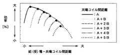
図3に、給電コイル10と給電側共鳴コイル12との距離と、給電効率との関係を示す。図において、共鳴コイル間の距離cはAcm、A+Bcm、A+2Bcm、A+3Bcm、A+4Bcm、A+5Bcmと変化させている。共鳴コイル間の距離cに応じて、最大効率が得られる距離a、bが変化することがわかる。定性的には、距離cが増大する程、最大効率が得られる距離a、bはともに増大する。但し、距離cが増大する程、効率自体は低下していく。受電コイル16と受電側共鳴コイル14との距離bと給電効率の関係についても同様である。 FIG. 3 shows the relationship between the distance between the feeding
図4に、距離比=(給電コイル10と給電側共鳴コイル12との距離a)/(共鳴コイル間の距離b)と給電効率との関係を示す。共鳴コイル間の距離cは、図3と同様にAcm、A+Bcm、A+2Bcm、A+3Bcm、A+4Bcm、A+5Bcmと変化させている。どの共鳴コイル間距離cにおいても、距離比が所定範囲内となるように設定することで、最大効率で給電が実行できることがわかる。(受電コイル16と受電側共鳴コイル14との距離b)/(共鳴コイル間の距離c)と給電効率の関係についても同様である。コイル間距離設定部26は、図3及び図4に示す関係に基づき、距離cが検出された場合に、距離cとの比が所定範囲内となるように距離a、bを設定する。 FIG. 4 shows a relationship between distance ratio = (distance a between the
図5に、給電−共鳴コイル間距離調整部28の一つの構成例を示す。円筒形状の収容ケース34内に給電コイル10及び給電側共鳴コイル12が、そのコイル軸方向が同一直線上に位置するように対向配置される。給電コイル10は収容ケース34内を擦動する支持台40に支持される。支持台40は、その内面に雌ネジが形成され、収容ケース34の外面に形成された雄ネジ38と螺合する移動台36に取り付けられる。移動台36はステッピングモータ32により回転駆動される。ステッピングモータ32が一方向に回転すると、収容ケース34の外面に形成された雄ネジと螺合する移動台36が収容ケース34に沿って移動し、給電コイル10も給電側共鳴コイル12に近づくように移動する。ステッピングモータ32が逆方向に回転すると、給電コイル10は給電側共鳴コイル12から離れるように移動する。ステッピングモータ32は、現在の距離と、コイル間距離設定部26で設定された距離との差に応じた角度だけ回転する。受電−共鳴コイル間距離調整部30についても同様である。 FIG. 5 shows one configuration example of the power supply-resonance coil
このように、本実施形態では、共鳴コイル間の距離cを検出し、この距離cに応じて距離a及び距離cを調整するので、距離cに応じた最大の効率で給電することができる。したがって、車載二次電池を効率的に充電することができる。 Thus, in this embodiment, since the distance c between the resonance coils is detected and the distance a and the distance c are adjusted according to the distance c, it is possible to supply power with the maximum efficiency according to the distance c. Therefore, the in-vehicle secondary battery can be efficiently charged.
本実施形態では、距離cに応じて距離a及び距離bを可変調整することで給電効率を維持ないし向上させているが、共鳴コイルに対して給電コイル10、受電コイル16のずれ量や角度を調整することもできる。 In the present embodiment, the power feeding efficiency is maintained or improved by variably adjusting the distance a and the distance b according to the distance c. However, the shift amount and angle of the
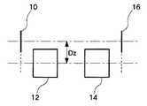
図6に、給電コイル10及び受電コイル16と共鳴コイル12,14の位置関係を示す。給電側共鳴コイル12と受電側共鳴コイル14はその軸方向が同一直線上に位置しているが、給電コイル10は給電側コイル12に対しその軸方向がDzだけずれて配置される。受電コイル16も受電側コイル14に対してその軸方向がDzだけずれて配置される。 FIG. 6 shows the positional relationship between the feeding
図7に、コイル軸間のずれ量Dzを変化させた場合の給電効率の変化を示す。共鳴コイル間の距離cは固定である。Dzが増大するに従い効率が増大し、Dzが所定値で効率が最大となり、Dzが所定値より増大すると逆に効率が減少する。したがって、給電−共鳴コイル間距離調整部28及び受電−共鳴コイル間距離調整部30は、距離cに応じて距離a、bを調整するのではなく、あるいは距離cに応じて距離a、bを調整することに加えて、ずれ量Dzも調整することで効率を向上させることができる。 FIG. 7 shows a change in power supply efficiency when the deviation amount Dz between the coil axes is changed. The distance c between the resonance coils is fixed. As Dz increases, the efficiency increases. When Dz is a predetermined value, the efficiency becomes maximum, and when Dz increases beyond the predetermined value, the efficiency decreases. Therefore, the power supply-resonance coil
図8に、給電コイル10及び受電コイル16と共鳴コイル12,14の他の位置関係を示す。給電コイル10、受電コイル16及び共鳴コイル12,14のコイル軸が同一直線上に位置している(図1と同様の場合)。但し、この例では給電コイル10、受電コイル16のコイル径Rを種々変化させる。 FIG. 8 shows another positional relationship between the feeding
図9に、コイル径Rを変化させた場合の給電効率の変化を示す。R=所定範囲で効率が最大となり、それ以外では効率が低下する。したがって、給電−共鳴コイル間距離調整部28及び受電−共鳴コイル間距離調整部30は、距離cに応じて距離a、bを調整するのではなく、あるいは距離cに応じて距離a、bを調整することに加えて、コイル径Rも調整することで効率を向上させることができる。 FIG. 9 shows a change in power supply efficiency when the coil diameter R is changed. Efficiency becomes maximum at R = predetermined range, and efficiency decreases otherwise. Therefore, the power supply-resonance coil
図10に、給電コイル10及び受電コイル16と共鳴コイル12,14の他の位置関係を示す。給電コイル10、受電コイル16のコイル軸が、共鳴コイル12,14のコイル軸に対してそれぞれ角度θだけ傾いている。なお、給電コイル10と受電コイル16の傾きの方向は互いに逆である。 FIG. 10 shows another positional relationship between the feeding
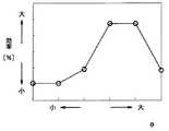
図11に、角度θを変化させた場合の給電効率の変化を示す。θ=所定範囲で効率が最大となり、それ以外では効率が低下する。したがって、給電−共鳴コイル間距離調整部28及び受電−共鳴コイル間距離調整部30は、距離cに応じて距離a、bを調整するのではなく、あるいは距離cに応じて距離a、bを調整することに加えて、角度θも調整することで効率を向上させることができる。 FIG. 11 shows a change in power supply efficiency when the angle θ is changed. The efficiency becomes maximum at θ = predetermined range, and the efficiency decreases at other times. Therefore, the power supply-resonance coil
図12に、給電コイル10及び受電コイル16と共鳴コイル12,14の他の位置関係を示す。給電コイル10、受電コイル16及び共鳴コイル12,14のコイル軸が同一直線上に位置している(図1と同様の場合)。但し、この例では給電コイル10については給電側コイル12との距離d1を変化させ、受電コイル16についてはそのコイル径R4を種々変化させる。 FIG. 12 shows another positional relationship between the feeding
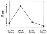
図13に、距離d1及びコイル径D4を変化させた場合の給電効率の変化を示す。(d1,R4)=(小,大)、(大,小)、(大,大)、(小,小)の場合である。(小,大)の場合を基準とすると、距離d1及びコイル径R4をともに変化させた(大,小)では給電効率は増大している。また、距離d1あるいはコイル径R4のいずれかを変化させた(大,大)、(小,小)の場合には効率増大の効果は少ない。したがって、給電−共鳴コイル間距離調整部28及び受電−共鳴コイル間距離調整部30は、距離cに応じて給電コイル10については距離d1を変化させ、受電コイル16についてはコイル径R4を変化させることで効率を向上させることができる。給電コイル10のコイル径を変化させるとともに、受電コイル16の距離を変化させてもよい。また、給電コイル10については距離d1を変化させ、受電コイル16についてはずれ量Dzを変化させてもよい。要するに、給電コイル10は距離、ずれ量、角度、コイル径のいずれかを変化させ、同時に、受電コイル16も距離、ずれ量、角度、コイル径のいずれかを変化させてもよい。 FIG. 13 shows changes in power supply efficiency when the distance d1 and the coil diameter D4 are changed. This is the case when (d1, R4) = (small, large), (large, small), (large, large), (small, small). When the case of (small, large) is used as a reference, the power supply efficiency increases when both the distance d1 and the coil diameter R4 are changed (large, small). Further, when either the distance d1 or the coil diameter R4 is changed (large, large) or (small, small), the effect of increasing the efficiency is small. Therefore, the power supply-resonance coil
以上説明したように、本実施形態では、共鳴コイル間の距離cに応じて給電コイル10の距離aと受電コイル16の距離b、給電コイル10のずれ量Dzと受電コイル16のずれ量Dz、給電コイル10の角度θと受電コイル16の角度θ、給電コイル10のコイル径Rと受電コイル16のコイル径Rの少なくともいずれか、あるいはこれらを任意に組み合わせて調整することで、距離cに応じた最大効率で給電することができる。共鳴コイル間の距離cに応じて給電コイル10、受電コイル12の共鳴コイル12,14に対する相対位置をそれぞれ調整するということができる。 As described above, in the present embodiment, the distance a of the feeding
例えば、まず距離cに応じて給電コイル10の距離a及び受電コイル16の距離bを調整して効率を最大化する。そして、得られた効率を所定のしきい値と大小比較する。得られた効率が所定のしきい値以上である場合には十分な効率であるとしてその状態において給電を行う。一方、得られた効率が所定のしきい値に達していない場合には、効率が十分でないとして、次に給電コイル10及び受電コイル16のずれ量Dzを調整して効率を最大化する。そして、得られた効率を再びしきい値と大小比較する。得られた効率が所定のしきい値以上である場合にはその状態において給電を行う。一方、得られた効率が所定のしきい値に達していない場合には、効率が未だ十分でないとして、次に給電コイル10及び受電コイル16の角度θを調整する。そして、得られた効率を再びしきい値と大小比較する。得られた効率が所定のしきい値に達していない場合には、車両等の移動体の乗員にその旨を報知し、停車位置を調整して再度給電を行うように指示する。あるいは、車両の駆動制御手段が自動で車両位置を微調整してもよい。まず角度θを調整した後にずれ量Dzの調整を行ってもよい。図7と図11とを比較すると、ずれ量Dzを調整した方が角度θを調整するよりも高い効率が得られる。したがって、一般的にはずれ量Dzを優先的に調整するのが好適であろう。もちろん、
(1)距離a、bの調整
(2)ずれ量Dzの調整
(3)コイル径Rの調整
(4)角度θの調整
は互いに独立の調整であり、これらの各調整を任意の順序で行って効率を最大化してもよい。以下は、調整順序の例示である。
(1)→(2)→(4)
(1)→(4)→(2)
(1)→(3)
(2)→(1)→(3)
(4)→(1)→(3)
(3)→(1)For example, first, the distance a of the feeding
(1) Adjustment of distances a and b (2) Adjustment of deviation amount Dz (3) Adjustment of coil diameter R (4) Adjustment of angle θ is an independent adjustment, and these adjustments are performed in an arbitrary order. Efficiency may be maximized. The following is an example of the adjustment order.
(1) → (2) → (4)
(1) → (4) → (2)
(1) → (3)
(2) → (1) → (3)
(4) → (1) → (3)
(3) → (1)
なお、本実施形態において、それぞれのコイルの位置を特定しなくても、伝送効率と個々の距離との間にピーク特性を有する関係があることから、伝送効率を検出しながらそれが最大になるように調整してもよい。まず給電コイル10−共鳴コイル12間、及び受電コイル16−共鳴コイル14間のどちらか一方を所定範囲で動かして給電効率がほぼ最大となる位置に調整し、その後、他方を所定範囲で動かして給電効率がほぼ最大となる位置に調整する。 In the present embodiment, even if the position of each coil is not specified, there is a relationship having a peak characteristic between the transmission efficiency and each distance, so that it is maximized while detecting the transmission efficiency. You may adjust as follows. First, either one between the
10 給電コイル、12 給電側共鳴コイル、14 受電側共鳴コイル、16 受電コイル。 10 power supply coil, 12 power supply side resonance coil, 14 power reception side resonance coil, 16 power reception coil.
Claims (5)
Translated fromJapanese移動体に設けられた受電コイル及び受電側共鳴コイルと、
前記給電側共鳴コイルの位置を検出する手段と、
前記受電側共鳴コイルの位置を検出する手段と、
前記給電側共鳴コイルと前記受電側共鳴コイルとの間の距離が大きくなると、前記給電側共鳴コイルと前記給電コイルとの間の距離、及び前記受電側共鳴コイルと前記受電コイルとの間の距離をそれぞれ大きくなるように調整する手段と、
を有することを特徴とする給電システム。A feeding coil and a feeding-side resonance coil provided in the facility;
A power receiving coil and a power receiving resonance coil provided on the moving body;
Means for detecting the position of the feeding-side resonance coil;
Means for detecting a position of the power receiving resonance coil;
When the distance between the power receiving side resonance coiland the power supply side resonance coilincreases,the distance between the feeding coiland the power supply side resonance coil, andthe distance between the receiving coiland the power receiving side resonance coil Meansfor adjusting each tobecome larger ,
A power supply system comprising:
移動体に設けられた受電コイル及び受電側共鳴コイルと、
前記給電側共鳴コイルの位置を検出する手段と、
前記受電側共鳴コイルの位置を検出する手段と、
前記給電側共鳴コイルの位置及び前記受電側共鳴コイルの位置に応じて、前記給電側共鳴コイルに対する前記給電コイルの相対位置、及び前記受電側共鳴コイルに対する前記受電コイルの相対位置をそれぞれ調整する手段と、
を有し、
前記給電側共鳴コイルのコイル軸と前記給電コイルのコイル軸とが同一直線上に位置している状態から前記給電側共鳴コイルに対する前記給電コイルのコイル軸ずれ量を変化させて、給電効率が最大となるときの位置ずれ量を第1位置ずれ量とし、
前記受電側共鳴コイルのコイル軸と前記受電コイルのコイル軸とが同一直線上に位置している状態から前記受電側共鳴コイルに対する前記受電コイルのコイル軸ずれ量を変化させて、給電効率が最大となるときの位置ずれ量を第2位置ずれ量とし、
前記調整する手段は、前記給電側共鳴コイルと前記受電側共鳴コイルとの距離が大きくなると、前記給電側共鳴コイルに対する前記給電コイルのコイル軸ずれ量が前記第1位置ずれ量に近づくように前記給電側共鳴コイルに対する前記給電コイルの相対位置を調整するとともに、前記受電側共鳴コイルに対する前記受電コイルのコイル軸ずれ量が前記第2位置ずれ量に近づくように前記受電側共鳴コイルに対する前記受電コイルの相対位置をそれぞれ調整する
ことを特徴とする給電システム。A feeding coil and a feeding-side resonance coil provided in the facility;
A power receiving coil and a power receiving resonance coil provided on the moving body;
Means for detecting the position of the feeding-side resonance coil;
Means for detecting a position of the power receiving resonance coil;
Means for adjusting the relative position of the feeding coil with respect to the feeding-side resonance coil and the relative position of the receiving coil with respect to the receiving-side resonance coil, respectively, according to the position of the feeding-side resonance coil and the position of the receiving-side resonance coil When,
Have
When the coil axis of the power supply side resonance coil and the coil axis of the power supply coil are located on the same straight line, the amount of coil axis deviation of the power supply coil with respect to the power supply side resonance coil is changed to maximize the power supply efficiency. The amount of misalignment when
By changing the coil axis deviation amount of the power receiving coil with respect to the power receiving side resonance coil from the state where the coil axis of the power receiving side resonance coil and the coil axis of the power receiving coil are located on the same straight line, the power feeding efficiency is maximized. The amount of misalignment when becomes the second misalignment amount,
When the distance between the power supply side resonance coil and the power reception side resonance coil is increased, the adjusting means is configured such that the coil axis deviation amount of the power supply coil with respect to the power supply side resonance coil approaches the first positional deviation amount. The power receiving coil relative to the power receiving resonance coil is adjusted such that a relative position of the power feeding coil with respect to the power feeding resonance coil is adjusted, and a coil axis deviation amount of the power receiving coil with respect to the power receiving resonance coil approaches the second positional deviation amount. A power feeding system thatadjusts the relative position of each .
移動体に設けられた受電コイル及び受電側共鳴コイルと、
前記給電側共鳴コイルの位置を検出する手段と、
前記受電側共鳴コイルの位置を検出する手段と、
前記給電側共鳴コイルの位置及び前記受電側共鳴コイルの位置に応じて、前記給電側共鳴コイルに対する前記給電コイルの相対位置、及び前記受電側共鳴コイルに対する前記受電コイルの相対位置をそれぞれ調整する手段と、
を有し、
前記給電側共鳴コイルに対する前記給電コイルのなす角度を変化させて、給電効率が最大となるときの角度範囲を第1角度範囲とし、
前記受電側共鳴コイルに対する前記受電コイルのなす角度を変化させて、給電効率が最大となるときの角度範囲を第2角度範囲とし、
前記調整する手段は、前記給電側共鳴コイルと前記受電側共鳴コイルとの距離が大きくなると、前記給電側共鳴コイルに対する前記給電コイルのなす角度が前記第1角度範囲に近づくように前記給電側共鳴コイルに対する前記給電コイルのなす角度を調整するとともに、前記受電側共鳴コイルに対する前記受電コイルのなす角度が前記第2角度範囲に近づくように前記受電側共鳴コイルに対する前記受電コイルのなす角度をそれぞれ調整する
ことを特徴とする給電システム。A feeding coil and a feeding-side resonance coil provided in the facility;
A power receiving coil and a power receiving resonance coil provided on the moving body;
Means for detecting the position of the feeding-side resonance coil;
Means for detecting a position of the power receiving resonance coil;
Means for adjusting the relative position of the feeding coil with respect to the feeding-side resonance coil and the relative position of the receiving coil with respect to the receiving-side resonance coil, respectively, according to the position of the feeding-side resonance coil and the position of the receiving-side resonance coil When,
Have
By changing the angle formed by the power supply coil with respect to the power supply side resonance coil, the angle range when the power supply efficiency becomes maximum is the first angle range,
By changing the angle formed by the power receiving coil with respect to the power receiving side resonance coil, the angle range when the power feeding efficiency is maximized is set as the second angle range,
The adjusting means adjusts the power feeding side resonance such that an angle formed by the power feeding coil with respect to the power feeding side resonance coil approaches the first angle range when a distance between the power feeding side resonance coil and the power receiving side resonance coil increases. The angle formed by the power feeding coil with respect to the coil is adjusted, and the angle formed by the power receiving coil with respect to the power receiving resonance coil is adjusted so that the angle between the power receiving coil with respect to the power receiving resonance coil approaches the second angle range. A power supply system characterizedby that.
前記調整する手段は、前記給電側共鳴コイルと前記受電側共鳴コイルとの距離が大きくなると、前記給電側共鳴コイルに対する前記給電コイルのコイル径、及び前記受電側共鳴コイルに対する前記受電コイルのコイル径が小さくなるように各コイル径を調整する
ことを特徴とする給電システム。The system of claim 1, wherein
Whenthe distance between the power supply side resonance coil and the power reception side resonance coil increases , the adjustment means adjuststhe coil diameter of the power supply coil relative to the power supply side resonance coil and the coil diameter of the power reception coil relative to the power reception side resonance coil. Each coil diameter is adjusted so that becomes small .
移動体に設けられた受電コイル及び受電側共鳴コイルと、
電力の伝送効率を表す給電効率を検出する手段と、
施設付近に移動体が停止した後に、前記給電側共鳴コイルと前記受電側共鳴コイルとの間の距離を第1距離とし、前記給電コイルと前記給電側共鳴コイルとの間の距離を第2距離とし、前記受電コイルと前記受電側共鳴コイルとの間の距離を第3距離とすると、
前記第1距離に対する前記第2距離の比及び前記第1距離に対する前記第3距離の比が所定の範囲内となるように、前記給電コイルと前記給電側共鳴コイルの相対位置及び前記受電コイルと前記受電側共鳴コイルの相対位置を所定範囲内で変更する手段と、
を有することを特徴とする給電システム。A feeding coil and a feeding-side resonance coil provided in the facility;
A power receiving coil and a power receiving resonance coil provided on the moving body;
Means for detecting power supply efficiency representing power transmission efficiency;
After the moving body stops near the facility, the distance between the power supply side resonance coil and the power reception side resonance coil is defined as a first distance, and the distance between the power supply coil and the power supply side resonance coil is defined as a second distance. And when the distance between the power receiving coil and the power receiving resonance coil is a third distance,
The relative position of the power feeding coil and the power feeding side resonance coil and the power receiving coil so that the ratio of the second distance to the first distance and the ratio of the third distance to the first distance are within a predetermined range. Means for changing the relative position of the power receiving resonance coil within a predetermined range;
Power supply system, characterized in thatit comprises a.
Priority Applications (2)
| Application Number | Priority Date | Filing Date | Title |
|---|---|---|---|
| JP2008293005AJP5308127B2 (en) | 2008-11-17 | 2008-11-17 | Power supply system |
| US12/588,354US8178995B2 (en) | 2008-11-17 | 2009-10-13 | Power supply system and method of controlling power supply system |
Applications Claiming Priority (1)
| Application Number | Priority Date | Filing Date | Title |
|---|---|---|---|
| JP2008293005AJP5308127B2 (en) | 2008-11-17 | 2008-11-17 | Power supply system |
Publications (2)
| Publication Number | Publication Date |
|---|---|
| JP2010124522A JP2010124522A (en) | 2010-06-03 |
| JP5308127B2true JP5308127B2 (en) | 2013-10-09 |
Family
ID=42171489
Family Applications (1)
| Application Number | Title | Priority Date | Filing Date |
|---|---|---|---|
| JP2008293005AActiveJP5308127B2 (en) | 2008-11-17 | 2008-11-17 | Power supply system |
Country Status (2)
| Country | Link |
|---|---|
| US (1) | US8178995B2 (en) |
| JP (1) | JP5308127B2 (en) |
Families Citing this family (170)
| Publication number | Priority date | Publication date | Assignee | Title |
|---|---|---|---|---|
| CN101860089B (en) | 2005-07-12 | 2013-02-06 | 麻省理工学院 | wireless non-radiative energy transfer |
| US7825543B2 (en) | 2005-07-12 | 2010-11-02 | Massachusetts Institute Of Technology | Wireless energy transfer |
| US8115448B2 (en) | 2007-06-01 | 2012-02-14 | Michael Sasha John | Systems and methods for wireless power |
| US9421388B2 (en) | 2007-06-01 | 2016-08-23 | Witricity Corporation | Power generation for implantable devices |
| CN102099958B (en) | 2008-05-14 | 2013-12-25 | 麻省理工学院 | Wireless power transfer including interference enhancement |
| US9473209B2 (en)* | 2008-08-20 | 2016-10-18 | Intel Corporation | Wireless power transfer apparatus and method thereof |
| US9106203B2 (en) | 2008-09-27 | 2015-08-11 | Witricity Corporation | Secure wireless energy transfer in medical applications |
| US8928276B2 (en) | 2008-09-27 | 2015-01-06 | Witricity Corporation | Integrated repeaters for cell phone applications |
| US9160203B2 (en) | 2008-09-27 | 2015-10-13 | Witricity Corporation | Wireless powered television |
| US8471410B2 (en) | 2008-09-27 | 2013-06-25 | Witricity Corporation | Wireless energy transfer over distance using field shaping to improve the coupling factor |
| US8461720B2 (en)* | 2008-09-27 | 2013-06-11 | Witricity Corporation | Wireless energy transfer using conducting surfaces to shape fields and reduce loss |
| US8598743B2 (en) | 2008-09-27 | 2013-12-03 | Witricity Corporation | Resonator arrays for wireless energy transfer |
| US9246336B2 (en) | 2008-09-27 | 2016-01-26 | Witricity Corporation | Resonator optimizations for wireless energy transfer |
| US9544683B2 (en) | 2008-09-27 | 2017-01-10 | Witricity Corporation | Wirelessly powered audio devices |
| US8686598B2 (en) | 2008-09-27 | 2014-04-01 | Witricity Corporation | Wireless energy transfer for supplying power and heat to a device |
| US8569914B2 (en) | 2008-09-27 | 2013-10-29 | Witricity Corporation | Wireless energy transfer using object positioning for improved k |
| US8947186B2 (en) | 2008-09-27 | 2015-02-03 | Witricity Corporation | Wireless energy transfer resonator thermal management |
| US8912687B2 (en) | 2008-09-27 | 2014-12-16 | Witricity Corporation | Secure wireless energy transfer for vehicle applications |
| US9184595B2 (en) | 2008-09-27 | 2015-11-10 | Witricity Corporation | Wireless energy transfer in lossy environments |
| US8957549B2 (en) | 2008-09-27 | 2015-02-17 | Witricity Corporation | Tunable wireless energy transfer for in-vehicle applications |
| US9318922B2 (en) | 2008-09-27 | 2016-04-19 | Witricity Corporation | Mechanically removable wireless power vehicle seat assembly |
| US9744858B2 (en) | 2008-09-27 | 2017-08-29 | Witricity Corporation | System for wireless energy distribution in a vehicle |
| US8933594B2 (en) | 2008-09-27 | 2015-01-13 | Witricity Corporation | Wireless energy transfer for vehicles |
| US8497601B2 (en) | 2008-09-27 | 2013-07-30 | Witricity Corporation | Wireless energy transfer converters |
| US9577436B2 (en) | 2008-09-27 | 2017-02-21 | Witricity Corporation | Wireless energy transfer for implantable devices |
| US8669676B2 (en) | 2008-09-27 | 2014-03-11 | Witricity Corporation | Wireless energy transfer across variable distances using field shaping with magnetic materials to improve the coupling factor |
| US8552592B2 (en)* | 2008-09-27 | 2013-10-08 | Witricity Corporation | Wireless energy transfer with feedback control for lighting applications |
| US8587153B2 (en) | 2008-09-27 | 2013-11-19 | Witricity Corporation | Wireless energy transfer using high Q resonators for lighting applications |
| US9105959B2 (en) | 2008-09-27 | 2015-08-11 | Witricity Corporation | Resonator enclosure |
| US8643326B2 (en) | 2008-09-27 | 2014-02-04 | Witricity Corporation | Tunable wireless energy transfer systems |
| US8324759B2 (en)* | 2008-09-27 | 2012-12-04 | Witricity Corporation | Wireless energy transfer using magnetic materials to shape field and reduce loss |
| US9035499B2 (en) | 2008-09-27 | 2015-05-19 | Witricity Corporation | Wireless energy transfer for photovoltaic panels |
| US8963488B2 (en) | 2008-09-27 | 2015-02-24 | Witricity Corporation | Position insensitive wireless charging |
| US8466583B2 (en) | 2008-09-27 | 2013-06-18 | Witricity Corporation | Tunable wireless energy transfer for outdoor lighting applications |
| US8400017B2 (en) | 2008-09-27 | 2013-03-19 | Witricity Corporation | Wireless energy transfer for computer peripheral applications |
| US8772973B2 (en) | 2008-09-27 | 2014-07-08 | Witricity Corporation | Integrated resonator-shield structures |
| US9093853B2 (en) | 2008-09-27 | 2015-07-28 | Witricity Corporation | Flexible resonator attachment |
| US8922066B2 (en) | 2008-09-27 | 2014-12-30 | Witricity Corporation | Wireless energy transfer with multi resonator arrays for vehicle applications |
| US8487480B1 (en) | 2008-09-27 | 2013-07-16 | Witricity Corporation | Wireless energy transfer resonator kit |
| US9601261B2 (en) | 2008-09-27 | 2017-03-21 | Witricity Corporation | Wireless energy transfer using repeater resonators |
| US8587155B2 (en)* | 2008-09-27 | 2013-11-19 | Witricity Corporation | Wireless energy transfer using repeater resonators |
| US8907531B2 (en) | 2008-09-27 | 2014-12-09 | Witricity Corporation | Wireless energy transfer with variable size resonators for medical applications |
| US8901778B2 (en) | 2008-09-27 | 2014-12-02 | Witricity Corporation | Wireless energy transfer with variable size resonators for implanted medical devices |
| US8937408B2 (en) | 2008-09-27 | 2015-01-20 | Witricity Corporation | Wireless energy transfer for medical applications |
| US8304935B2 (en)* | 2008-09-27 | 2012-11-06 | Witricity Corporation | Wireless energy transfer using field shaping to reduce loss |
| US8629578B2 (en) | 2008-09-27 | 2014-01-14 | Witricity Corporation | Wireless energy transfer systems |
| US8723366B2 (en) | 2008-09-27 | 2014-05-13 | Witricity Corporation | Wireless energy transfer resonator enclosures |
| US8461722B2 (en) | 2008-09-27 | 2013-06-11 | Witricity Corporation | Wireless energy transfer using conducting surfaces to shape field and improve K |
| US9515494B2 (en) | 2008-09-27 | 2016-12-06 | Witricity Corporation | Wireless power system including impedance matching network |
| US8441154B2 (en) | 2008-09-27 | 2013-05-14 | Witricity Corporation | Multi-resonator wireless energy transfer for exterior lighting |
| US9601266B2 (en) | 2008-09-27 | 2017-03-21 | Witricity Corporation | Multiple connected resonators with a single electronic circuit |
| US9065423B2 (en) | 2008-09-27 | 2015-06-23 | Witricity Corporation | Wireless energy distribution system |
| US8692412B2 (en) | 2008-09-27 | 2014-04-08 | Witricity Corporation | Temperature compensation in a wireless transfer system |
| US8482158B2 (en) | 2008-09-27 | 2013-07-09 | Witricity Corporation | Wireless energy transfer using variable size resonators and system monitoring |
| US8901779B2 (en) | 2008-09-27 | 2014-12-02 | Witricity Corporation | Wireless energy transfer with resonator arrays for medical applications |
| US8410636B2 (en) | 2008-09-27 | 2013-04-02 | Witricity Corporation | Low AC resistance conductor designs |
| US8946938B2 (en) | 2008-09-27 | 2015-02-03 | Witricity Corporation | Safety systems for wireless energy transfer in vehicle applications |
| EP3179640A1 (en)* | 2008-09-27 | 2017-06-14 | WiTricity Corporation | Wireless energy transfer systems |
| US8692410B2 (en)* | 2008-09-27 | 2014-04-08 | Witricity Corporation | Wireless energy transfer with frequency hopping |
| US8476788B2 (en) | 2008-09-27 | 2013-07-02 | Witricity Corporation | Wireless energy transfer with high-Q resonators using field shaping to improve K |
| US8461721B2 (en) | 2008-09-27 | 2013-06-11 | Witricity Corporation | Wireless energy transfer using object positioning for low loss |
| US9601270B2 (en) | 2008-09-27 | 2017-03-21 | Witricity Corporation | Low AC resistance conductor designs |
| US9396867B2 (en) | 2008-09-27 | 2016-07-19 | Witricity Corporation | Integrated resonator-shield structures |
| US20100259110A1 (en)* | 2008-09-27 | 2010-10-14 | Kurs Andre B | Resonator optimizations for wireless energy transfer |
| US8362651B2 (en) | 2008-10-01 | 2013-01-29 | Massachusetts Institute Of Technology | Efficient near-field wireless energy transfer using adiabatic system variations |
| CN102209647B (en)* | 2008-11-07 | 2013-11-13 | 丰田自动车株式会社 | Vehicle power supply system, electric vehicle, and vehicle power supply equipment |
| JP5258521B2 (en)* | 2008-11-14 | 2013-08-07 | トヨタ自動車株式会社 | Power supply system |
| JP5135204B2 (en)* | 2008-12-26 | 2013-02-06 | 株式会社日立製作所 | Non-contact power transmission system and load device in the non-contact power transmission system |
| JP5262785B2 (en)* | 2009-02-09 | 2013-08-14 | 株式会社豊田自動織機 | Non-contact power transmission device |
| JP5365306B2 (en)* | 2009-03-31 | 2013-12-11 | 富士通株式会社 | Wireless power supply system |
| JP5353376B2 (en)* | 2009-03-31 | 2013-11-27 | 富士通株式会社 | Wireless power device and wireless power receiving method |
| JP4915438B2 (en)* | 2009-07-24 | 2012-04-11 | Tdk株式会社 | Wireless power supply apparatus and wireless power transmission system |
| WO2011064879A1 (en)* | 2009-11-27 | 2011-06-03 | 富士通株式会社 | Electrical power transmission device |
| JP5505425B2 (en)* | 2009-12-16 | 2014-05-28 | 富士通株式会社 | Magnetic field resonance power transmission device, magnetic field resonance power reception device, magnetic field resonance power transmission / reception system, and magnetic field resonance power transmission / reception method |
| JP5526795B2 (en)* | 2010-01-15 | 2014-06-18 | ソニー株式会社 | Wireless power supply system |
| JP5463932B2 (en) | 2010-01-26 | 2014-04-09 | ソニー株式会社 | Information processing apparatus, information processing method, and information processing system |
| US9024480B2 (en)* | 2010-01-27 | 2015-05-05 | Honeywell International Inc. | Controller for wireless energy transfer |
| US8823214B2 (en) | 2010-01-27 | 2014-09-02 | Honeywell International Inc. | Wireless energy transfer |
| JP5527590B2 (en)* | 2010-01-29 | 2014-06-18 | 国立大学法人 東京大学 | Power transmission device, power reception device, and power transmission system |
| JP2011189895A (en)* | 2010-03-16 | 2011-09-29 | Toyota Central R&D Labs Inc | Mobile power feeder |
| JP5290228B2 (en)* | 2010-03-30 | 2013-09-18 | 株式会社日本自動車部品総合研究所 | Voltage detector, abnormality detection device, contactless power transmission device, contactless power receiving device, contactless power feeding system, and vehicle |
| US8841881B2 (en) | 2010-06-02 | 2014-09-23 | Bryan Marc Failing | Energy transfer with vehicles |
| JP5524724B2 (en)* | 2010-06-08 | 2014-06-18 | 株式会社東海理化電機製作所 | Vehicle power supply device |
| JP2012005308A (en)* | 2010-06-21 | 2012-01-05 | Panasonic Corp | Wireless power transmission system |
| IT1400748B1 (en)* | 2010-06-30 | 2013-07-02 | St Microelectronics Srl | SYSTEM FOR WIRELESS TRANSFER OF ENERGY BETWEEN TWO DEVICES AND SIMULTANEOUS DATA TRANSFER. |
| WO2012001291A2 (en)* | 2010-07-01 | 2012-01-05 | Renault S.A.S. | Contactless charging of a motor vehicle battery |
| FR2962263B1 (en)* | 2010-07-01 | 2013-06-28 | Renault Sa | NON-CONTACT CHARGE OF A MOTOR VEHICLE BATTERY |
| US20130119781A1 (en)* | 2010-07-29 | 2013-05-16 | Toyota Jidosha Kabushiki Kaisha | Resonance type non-contact power supply system |
| KR101757298B1 (en)* | 2010-08-19 | 2017-07-12 | 엘지전자 주식회사 | Wireless power transmission method and apparatus |
| US9602168B2 (en) | 2010-08-31 | 2017-03-21 | Witricity Corporation | Communication in wireless energy transfer systems |
| WO2012042902A1 (en)* | 2010-10-01 | 2012-04-05 | パナソニック株式会社 | Electricity supply system for electric automobile, and electric automobile and power supply device used in said system |
| WO2012058466A1 (en)* | 2010-10-29 | 2012-05-03 | Qualcomm Incorporated | Wireless energy transfer via coupled parasitic resonators |
| CN102640395B (en) | 2010-12-01 | 2015-05-06 | 丰田自动车株式会社 | Non-contact power supply device, vehicle and control method of non-contact power supply system |
| JP5725843B2 (en)* | 2010-12-21 | 2015-05-27 | 矢崎総業株式会社 | Power supply system |
| WO2012086625A1 (en) | 2010-12-21 | 2012-06-28 | 矢崎総業株式会社 | Power feed system |
| KR101842180B1 (en)* | 2010-12-24 | 2018-03-26 | 가부시키가이샤 한도오따이 에네루기 켄큐쇼 | Power feeding device and contactless power feeding system provided with power feeding device |
| JP2012165527A (en)* | 2011-02-04 | 2012-08-30 | Nitto Denko Corp | Wireless power supply system |
| US9035500B2 (en) | 2011-03-01 | 2015-05-19 | Tdk Corporation | Wireless power feeder, wireless power receiver, and wireless power transmission system, and coil |
| JP2012191699A (en)* | 2011-03-09 | 2012-10-04 | Hitachi Maxell Energy Ltd | Wireless power transmission method utilizing magnetic field resonance |
| WO2012128093A1 (en) | 2011-03-18 | 2012-09-27 | 矢崎総業株式会社 | Power supply system |
| JP5968596B2 (en) | 2011-04-11 | 2016-08-10 | 日東電工株式会社 | Wireless power supply system |
| US10090885B2 (en) | 2011-04-13 | 2018-10-02 | Qualcomm Incorporated | Antenna alignment and vehicle guidance for wireless charging of electric vehicles |
| US20140055089A1 (en)* | 2011-05-19 | 2014-02-27 | Toyota Jidosha Kabushiki Kaisha | Power reception device, power transmission device and power transfer system |
| WO2012157115A1 (en)* | 2011-05-19 | 2012-11-22 | トヨタ自動車株式会社 | Power reception apparatus, vehicle provided therewith, power feeding equipment, and power feeding system |
| US9099885B2 (en)* | 2011-06-17 | 2015-08-04 | Semiconductor Energy Laboratory Co., Ltd. | Wireless power feeding system |
| US20120326523A1 (en) | 2011-06-22 | 2012-12-27 | Noriyuki Fukushima | Wireless power feeder, wireless power receiver, and wireless power transmission system |
| JP5825882B2 (en)* | 2011-06-30 | 2015-12-02 | 矢崎総業株式会社 | Power supply system |
| WO2013002241A1 (en)* | 2011-06-30 | 2013-01-03 | 矢崎総業株式会社 | Electrical supply system |
| EP2728711A1 (en)* | 2011-06-30 | 2014-05-07 | Yazaki Corporation | Power feeding system design method and power feeding system |
| US9893566B2 (en) | 2011-06-30 | 2018-02-13 | Yazaki Corporation | Power supply system |
| US9948145B2 (en) | 2011-07-08 | 2018-04-17 | Witricity Corporation | Wireless power transfer for a seat-vest-helmet system |
| CN108110907B (en) | 2011-08-04 | 2022-08-02 | 韦特里西提公司 | Tunable wireless power supply architecture |
| EP2754222B1 (en) | 2011-09-09 | 2015-11-18 | Witricity Corporation | Foreign object detection in wireless energy transfer systems |
| US20130062966A1 (en) | 2011-09-12 | 2013-03-14 | Witricity Corporation | Reconfigurable control architectures and algorithms for electric vehicle wireless energy transfer systems |
| JP5665710B2 (en)* | 2011-09-26 | 2015-02-04 | 株式会社東芝 | Wireless power transmission system, power transmission device and power reception device |
| EP2768116A4 (en)* | 2011-10-12 | 2015-09-02 | Toyota Motor Co Ltd | POWER TRANSMISSION APPARATUS AND SYSTEM AND POWER RECEPTION APPARATUS |
| US9318257B2 (en) | 2011-10-18 | 2016-04-19 | Witricity Corporation | Wireless energy transfer for packaging |
| US9697952B2 (en)* | 2011-10-27 | 2017-07-04 | Toyota Jidosha Kabushiki Kaisha | Non-contact electric power reception device, non-contact electric power transmission device, and non-contact electric power transmission and reception system |
| CA2853824A1 (en) | 2011-11-04 | 2013-05-10 | Witricity Corporation | Wireless energy transfer modeling tool |
| JP5849630B2 (en)* | 2011-11-14 | 2016-01-27 | 富士通株式会社 | Power repeater |
| JP2015508987A (en) | 2012-01-26 | 2015-03-23 | ワイトリシティ コーポレーションWitricity Corporation | Wireless energy transmission with reduced field |
| WO2013145143A1 (en) | 2012-03-28 | 2013-10-03 | 富士通株式会社 | Power transmitting apparatus |
| JP6095957B2 (en) | 2012-04-17 | 2017-03-15 | 日東電工株式会社 | Wireless power transmission device, power feeding device, and power receiving device |
| US9343922B2 (en) | 2012-06-27 | 2016-05-17 | Witricity Corporation | Wireless energy transfer for rechargeable batteries |
| US9287607B2 (en) | 2012-07-31 | 2016-03-15 | Witricity Corporation | Resonator fine tuning |
| US9595378B2 (en) | 2012-09-19 | 2017-03-14 | Witricity Corporation | Resonator enclosure |
| EP2909912B1 (en) | 2012-10-19 | 2022-08-10 | WiTricity Corporation | Foreign object detection in wireless energy transfer systems |
| JP6065526B2 (en)* | 2012-11-06 | 2017-01-25 | 株式会社Ihi | Non-contact power feeding device |
| JPWO2014076801A1 (en)* | 2012-11-15 | 2016-09-08 | 中国電力株式会社 | Non-contact power supply system and control method of non-contact power supply system |
| US9842684B2 (en) | 2012-11-16 | 2017-12-12 | Witricity Corporation | Systems and methods for wireless power system with improved performance and/or ease of use |
| JP2014168359A (en)* | 2013-02-28 | 2014-09-11 | Nitto Denko Corp | Wireless power transmission device, power supply control method of wireless power transmission device, and method of manufacturing wireless power transmission device |
| JP2014204452A (en) | 2013-04-01 | 2014-10-27 | 日東電工株式会社 | Power reception apparatus |
| JP6138620B2 (en)* | 2013-07-30 | 2017-05-31 | 本田技研工業株式会社 | Contactless power supply system |
| US9857821B2 (en) | 2013-08-14 | 2018-01-02 | Witricity Corporation | Wireless power transfer frequency adjustment |
| US10038340B2 (en)* | 2013-10-21 | 2018-07-31 | Electronics And Telecommunications Research Institute | Wireless power transmission method and apparatus for improving spectrum efficiency and space efficiency based on impedance matching and relay resonance |
| WO2015087400A1 (en)* | 2013-12-10 | 2015-06-18 | 中国電力株式会社 | Power-transmitting device, power-feeding system, and device for adjusting impedance of electrical circuit |
| KR20160096085A (en)* | 2013-12-10 | 2016-08-12 | 쥬코쿠 덴료쿠 가부시키 가이샤 | Power-transmitting device and power-feeding system |
| US9780573B2 (en) | 2014-02-03 | 2017-10-03 | Witricity Corporation | Wirelessly charged battery system |
| JP2015146705A (en)* | 2014-02-04 | 2015-08-13 | タイコエレクトロニクスジャパン合同会社 | Contactless charger |
| US9952266B2 (en) | 2014-02-14 | 2018-04-24 | Witricity Corporation | Object detection for wireless energy transfer systems |
| JP6280404B2 (en)* | 2014-03-18 | 2018-02-14 | Ihi運搬機械株式会社 | Non-contact power feeding system and vehicle power feeding device |
| EP3128644B1 (en) | 2014-03-18 | 2020-11-18 | IHI Corporation | Contactless power supply system and vehicle power supply system |
| JP6228720B2 (en)* | 2014-03-21 | 2017-11-08 | Ihi運搬機械株式会社 | Non-contact power feeding system and vehicle power feeding device |
| WO2015155838A1 (en)* | 2014-04-08 | 2015-10-15 | 日産自動車株式会社 | Contactless electricity supply system and contactless electricity reception device |
| US9892849B2 (en) | 2014-04-17 | 2018-02-13 | Witricity Corporation | Wireless power transfer systems with shield openings |
| US9842687B2 (en) | 2014-04-17 | 2017-12-12 | Witricity Corporation | Wireless power transfer systems with shaped magnetic components |
| US9837860B2 (en) | 2014-05-05 | 2017-12-05 | Witricity Corporation | Wireless power transmission systems for elevators |
| JP2017518018A (en) | 2014-05-07 | 2017-06-29 | ワイトリシティ コーポレーションWitricity Corporation | Foreign object detection in wireless energy transmission systems |
| KR20150139288A (en)* | 2014-06-03 | 2015-12-11 | 현대자동차주식회사 | Apparatus and method for transmitting wireless power |
| US9954375B2 (en) | 2014-06-20 | 2018-04-24 | Witricity Corporation | Wireless power transfer systems for surfaces |
| CN107258046B (en) | 2014-07-08 | 2020-07-17 | 无线电力公司 | Resonator equalization in wireless power transfer systems |
| US10574091B2 (en) | 2014-07-08 | 2020-02-25 | Witricity Corporation | Enclosures for high power wireless power transfer systems |
| JP6179730B2 (en)* | 2014-09-19 | 2017-08-16 | パナソニックIpマネジメント株式会社 | Power receiving device, non-contact power transmission system, and charging method |
| JP6146585B2 (en)* | 2014-09-19 | 2017-06-14 | パナソニックIpマネジメント株式会社 | Non-contact power transmission system |
| JP5897777B1 (en)* | 2014-12-24 | 2016-03-30 | 中国電力株式会社 | Non-contact power feeding system, power receiving device, and power transmitting device |
| US9843217B2 (en) | 2015-01-05 | 2017-12-12 | Witricity Corporation | Wireless energy transfer for wearables |
| JP6485080B2 (en)* | 2015-02-02 | 2019-03-20 | 株式会社Ihi | Coil device mounting structure and coil device |
| JP2015213428A (en)* | 2015-06-24 | 2015-11-26 | 日東電工株式会社 | Wireless power supply system |
| US10248899B2 (en) | 2015-10-06 | 2019-04-02 | Witricity Corporation | RFID tag and transponder detection in wireless energy transfer systems |
| US9929721B2 (en) | 2015-10-14 | 2018-03-27 | Witricity Corporation | Phase and amplitude detection in wireless energy transfer systems |
| WO2017070227A1 (en) | 2015-10-19 | 2017-04-27 | Witricity Corporation | Foreign object detection in wireless energy transfer systems |
| WO2017070009A1 (en) | 2015-10-22 | 2017-04-27 | Witricity Corporation | Dynamic tuning in wireless energy transfer systems |
| US10075019B2 (en) | 2015-11-20 | 2018-09-11 | Witricity Corporation | Voltage source isolation in wireless power transfer systems |
| WO2017136491A1 (en) | 2016-02-02 | 2017-08-10 | Witricity Corporation | Controlling wireless power transfer systems |
| CN114123540B (en) | 2016-02-08 | 2024-08-20 | 韦特里西提公司 | Variable capacitance device and high-power wireless energy transmission system |
| DE102016108446A1 (en)* | 2016-05-06 | 2017-11-09 | Terex Mhps Gmbh | System and method for determining the position of a transport vehicle and transport vehicle |
| KR20180064218A (en)* | 2016-12-05 | 2018-06-14 | 동원건설산업 주식회사 | Contactlesspower supplying device for small electric vehicle |
| WO2019006376A1 (en) | 2017-06-29 | 2019-01-03 | Witricity Corporation | Protection and control of wireless power systems |
| CN108705945B (en)* | 2018-05-24 | 2020-08-04 | 特路(北京)科技有限公司 | Vehicle-mounted wireless charging receiving device, electric vehicle and wireless charging method thereof |
| EP3795408A1 (en)* | 2019-09-23 | 2021-03-24 | Ningbo Geely Automobile Research & Development Co. Ltd. | A device for a wireless power transfer system for charging a vehicle |
Family Cites Families (108)
| Publication number | Priority date | Publication date | Assignee | Title |
|---|---|---|---|---|
| US4400724A (en)* | 1981-06-08 | 1983-08-23 | The United States Of America As Represented By The Secretary Of The Army | Virtual space teleconference system |
| US4573072A (en)* | 1984-03-21 | 1986-02-25 | Actv Inc. | Method for expanding interactive CATV displayable choices for a given channel capacity |
| US4602279A (en)* | 1984-03-21 | 1986-07-22 | Actv, Inc. | Method for providing targeted profile interactive CATV displays |
| IT1219523B (en)* | 1987-04-06 | 1990-05-18 | Kiyohiro Kanno | PEARL CONNECTION DEVICE OR OTHER JEWELERY ITEMS TO FORM NECKLACES OR SIMILAR |
| US4847698A (en)* | 1987-07-16 | 1989-07-11 | Actv, Inc. | Interactive television system for providing full motion synched compatible audio/visual displays |
| US4918516A (en)* | 1987-10-26 | 1990-04-17 | 501 Actv, Inc. | Closed circuit television system having seamless interactive television programming and expandable user participation |
| CA1337132C (en)* | 1988-07-15 | 1995-09-26 | Robert Filepp | Reception system for an interactive computer network and method of operation |
| US5220501A (en)* | 1989-12-08 | 1993-06-15 | Online Resources, Ltd. | Method and system for remote delivery of retail banking services |
| US5870724A (en)* | 1989-12-08 | 1999-02-09 | Online Resources & Communications Corporation | Targeting advertising in a home retail banking delivery service |
| JPH03223263A (en)* | 1990-01-26 | 1991-10-02 | Showa Shell Sekiyu Kk | Liquid crystal compound |
| US5136633A (en)* | 1990-01-30 | 1992-08-04 | Visa International Service Association | International authorization system |
| US5861881A (en)* | 1991-11-25 | 1999-01-19 | Actv, Inc. | Interactive computer system for providing an interactive presentation with personalized video, audio and graphics responses for multiple viewers |
| US5724091A (en)* | 1991-11-25 | 1998-03-03 | Actv, Inc. | Compressed digital data interactive program system |
| DE4236286A1 (en)* | 1992-10-28 | 1994-05-05 | Daimler Benz Ag | Method and arrangement for automatic contactless charging |
| CA2121151A1 (en)* | 1993-04-16 | 1994-10-17 | Trevor Lambert | Method and apparatus for automatic insertion of a television signal from a remote source |
| US6196458B1 (en)* | 1997-12-01 | 2001-03-06 | Walker Digital, Llc | Method and apparatus for printing a billing statement to provide supplementary product sales |
| US5794207A (en)* | 1996-09-04 | 1998-08-11 | Walker Asset Management Limited Partnership | Method and apparatus for a cryptographically assisted commercial network system designed to facilitate buyer-driven conditional purchase offers |
| US5537141A (en)* | 1994-04-15 | 1996-07-16 | Actv, Inc. | Distance learning system providing individual television participation, audio responses and memory for every student |
| US5768521A (en)* | 1994-05-16 | 1998-06-16 | Intel Corporation | General purpose metering mechanism for distribution of electronic information |
| US5864604A (en)* | 1994-05-20 | 1999-01-26 | General Patent Corp | Method of providing message service for limited access telecommunications |
| US6182052B1 (en)* | 1994-06-06 | 2001-01-30 | Huntington Bancshares Incorporated | Communications network interface for user friendly interactive access to online services |
| US5632007A (en)* | 1994-09-23 | 1997-05-20 | Actv, Inc. | Interactive system and method for offering expert based interactive programs |
| US5760838A (en)* | 1994-09-30 | 1998-06-02 | Intel Corporation | Method and system for configuring a display |
| EP0788714B1 (en)* | 1994-10-24 | 2006-03-22 | Intel Corporation | Video indexing protocol |
| US5534911A (en)* | 1994-11-02 | 1996-07-09 | Levitan; Gutman | Virtual personal channel in a television system |
| US5715403A (en)* | 1994-11-23 | 1998-02-03 | Xerox Corporation | System for controlling the distribution and use of digital works having attached usage rights where the usage rights are defined by a usage rights grammar |
| US5521444A (en)* | 1994-11-30 | 1996-05-28 | Honeywell Inc. | Apparatus for transferring electrical power from a stationary device to a rotating device without the use of brushes or contacts |
| US5664110A (en)* | 1994-12-08 | 1997-09-02 | Highpoint Systems, Inc. | Remote ordering system |
| US5892900A (en)* | 1996-08-30 | 1999-04-06 | Intertrust Technologies Corp. | Systems and methods for secure transaction management and electronic rights protection |
| CN101398871B (en)* | 1995-02-13 | 2011-05-18 | 英特特拉斯特技术公司 | Systems and methods for secure transaction management and electronic rights protection |
| US5812776A (en)* | 1995-06-07 | 1998-09-22 | Open Market, Inc. | Method of providing internet pages by mapping telephone number provided by client to URL and returning the same in a redirect command by server |
| US5701451A (en)* | 1995-06-07 | 1997-12-23 | International Business Machines Corporation | Method for fulfilling requests of a web browser |
| US5740549A (en)* | 1995-06-12 | 1998-04-14 | Pointcast, Inc. | Information and advertising distribution system and method |
| US5818441A (en)* | 1995-06-15 | 1998-10-06 | Intel Corporation | System and method for simulating two-way connectivity for one way data streams |
| US5758057A (en)* | 1995-06-21 | 1998-05-26 | Mitsubishi Denki Kabushiki Kaisha | Multi-media storage system |
| US5682196A (en)* | 1995-06-22 | 1997-10-28 | Actv, Inc. | Three-dimensional (3D) video presentation system providing interactive 3D presentation with personalized audio responses for multiple viewers |
| US5745360A (en)* | 1995-08-14 | 1998-04-28 | International Business Machines Corp. | Dynamic hypertext link converter system and process |
| US5742759A (en)* | 1995-08-18 | 1998-04-21 | Sun Microsystems, Inc. | Method and system for facilitating access control to system resources in a distributed computer system |
| US5710887A (en)* | 1995-08-29 | 1998-01-20 | Broadvision | Computer system and method for electronic commerce |
| US5812769A (en)* | 1995-09-20 | 1998-09-22 | Infonautics Corporation | Method and apparatus for redirecting a user to a new location on the world wide web using relative universal resource locators |
| US5708845A (en)* | 1995-09-29 | 1998-01-13 | Wistendahl; Douglass A. | System for mapping hot spots in media content for interactive digital media program |
| US5774670A (en)* | 1995-10-06 | 1998-06-30 | Netscape Communications Corporation | Persistent client state in a hypertext transfer protocol based client-server system |
| DE19539801C2 (en)* | 1995-10-26 | 2001-04-19 | Ibm | Monitoring transactions with smart cards |
| US5745681A (en)* | 1996-01-11 | 1998-04-28 | Sun Microsystems, Inc. | Stateless shopping cart for the web |
| JPH09212549A (en)* | 1996-01-31 | 1997-08-15 | Hitachi Ltd | Electronic commerce method and system |
| US5761606A (en)* | 1996-02-08 | 1998-06-02 | Wolzien; Thomas R. | Media online services access via address embedded in video or audio program |
| US5751956A (en)* | 1996-02-21 | 1998-05-12 | Infoseek Corporation | Method and apparatus for redirection of server external hyper-link references |
| US5963915A (en)* | 1996-02-21 | 1999-10-05 | Infoseek Corporation | Secure, convenient and efficient system and method of performing trans-internet purchase transactions |
| US5774664A (en)* | 1996-03-08 | 1998-06-30 | Actv, Inc. | Enhanced video programming system and method for incorporating and displaying retrieved integrated internet information segments |
| US6018768A (en)* | 1996-03-08 | 2000-01-25 | Actv, Inc. | Enhanced video programming system and method for incorporating and displaying retrieved integrated internet information segments |
| US5778181A (en)* | 1996-03-08 | 1998-07-07 | Actv, Inc. | Enhanced video programming system and method for incorporating and displaying retrieved integrated internet information segments |
| US6012080A (en)* | 1996-03-27 | 2000-01-04 | Lucent Technologies Inc. | Method and apparatus for providing enhanced pay per view in a video server |
| US5964829A (en)* | 1996-03-27 | 1999-10-12 | Lucent Technologies Inc. | Method and apparatus for providing enhanced pay per view in a video server employing a coarse-grained striping scheme |
| US6240555B1 (en)* | 1996-03-29 | 2001-05-29 | Microsoft Corporation | Interactive entertainment system for presenting supplemental interactive content together with continuous video programs |
| US5822018A (en)* | 1996-04-02 | 1998-10-13 | Farmer; James O. | Method and apparatus for normalizing signal levels in a signal processing system |
| US5929849A (en)* | 1996-05-02 | 1999-07-27 | Phoenix Technologies, Ltd. | Integration of dynamic universal resource locators with television presentations |
| US6373950B1 (en)* | 1996-06-17 | 2002-04-16 | Hewlett-Packard Company | System, method and article of manufacture for transmitting messages within messages utilizing an extensible, flexible architecture |
| US5862339A (en)* | 1996-07-09 | 1999-01-19 | Webtv Networks, Inc. | Client connects to an internet access provider using algorithm downloaded from a central server based upon client's desired criteria after disconnected from the server |
| EP0823716A3 (en)* | 1996-08-07 | 1998-04-08 | SUMITOMO WIRING SYSTEMS, Ltd. | Magnetic coupling device for charging an electric vehicle |
| US6016504A (en)* | 1996-08-28 | 2000-01-18 | Infospace.Com, Inc. | Method and system for tracking the purchase of a product and services over the Internet |
| US20030005463A1 (en)* | 1999-09-30 | 2003-01-02 | Douglas B Macrae | Access to internet data through a television system |
| US5897622A (en)* | 1996-10-16 | 1999-04-27 | Microsoft Corporation | Electronic shopping and merchandising system |
| US5774666A (en)* | 1996-10-18 | 1998-06-30 | Silicon Graphics, Inc. | System and method for displaying uniform network resource locators embedded in time-based medium |
| US6374237B1 (en)* | 1996-12-24 | 2002-04-16 | Intel Corporation | Data set selection based upon user profile |
| US5818935A (en)* | 1997-03-10 | 1998-10-06 | Maa; Chia-Yiu | Internet enhanced video system |
| US6286045B1 (en)* | 1997-05-19 | 2001-09-04 | Matchlogic, Inc. | Information storage and delivery over a computer network using centralized intelligence to monitor and control the information being delivered |
| US6108706A (en)* | 1997-06-09 | 2000-08-22 | Microsoft Corporation | Transmission announcement system and method for announcing upcoming data transmissions over a broadcast network |
| US5864823A (en)* | 1997-06-25 | 1999-01-26 | Virtel Corporation | Integrated virtual telecommunication system for E-commerce |
| US6044469A (en)* | 1997-08-29 | 2000-03-28 | Preview Software | Software publisher or distributor configurable software security mechanism |
| US5960411A (en)* | 1997-09-12 | 1999-09-28 | Amazon.Com, Inc. | Method and system for placing a purchase order via a communications network |
| US6081830A (en)* | 1997-10-09 | 2000-06-27 | Gateway 2000, Inc. | Automatic linking to program-specific computer chat rooms |
| US6070191A (en)* | 1997-10-17 | 2000-05-30 | Lucent Technologies Inc. | Data distribution techniques for load-balanced fault-tolerant web access |
| US6216157B1 (en)* | 1997-11-14 | 2001-04-10 | Yahoo! Inc. | Method and apparatus for a client-server system with heterogeneous clients |
| US6189785B1 (en)* | 1998-04-14 | 2001-02-20 | International Check Services | Demand deposit account data processing system |
| US6339826B2 (en)* | 1998-05-05 | 2002-01-15 | International Business Machines Corp. | Client-server system for maintaining a user desktop consistent with server application user access permissions |
| US6698020B1 (en)* | 1998-06-15 | 2004-02-24 | Webtv Networks, Inc. | Techniques for intelligent video ad insertion |
| US6420555B1 (en)* | 1998-06-16 | 2002-07-16 | Societe De Conseils De Recherches Et D'applications Scientifiques, S.A.S. | Imidazolyl derivatives |
| US6446109B2 (en)* | 1998-06-29 | 2002-09-03 | Sun Microsystems, Inc. | Application computing environment |
| US6898762B2 (en)* | 1998-08-21 | 2005-05-24 | United Video Properties, Inc. | Client-server electronic program guide |
| US6338094B1 (en)* | 1998-09-08 | 2002-01-08 | Webtv Networks, Inc. | Method, device and system for playing a video file in response to selecting a web page link |
| US20010020242A1 (en)* | 1998-11-16 | 2001-09-06 | Amit Gupta | Method and apparatus for processing client information |
| US6282713B1 (en)* | 1998-12-21 | 2001-08-28 | Sony Corporation | Method and apparatus for providing on-demand electronic advertising |
| US6282517B1 (en)* | 1999-01-14 | 2001-08-28 | Autobytel.Com, Inc. | Real time communication of purchase requests |
| US6401085B1 (en)* | 1999-03-05 | 2002-06-04 | Accenture Llp | Mobile communication and computing system and method |
| US6560777B2 (en)* | 1999-04-07 | 2003-05-06 | Webtv Networks, Inc. | Broadcast enhancement trigger addressed to multiple uniquely addressed information resources |
| US6571392B1 (en)* | 1999-04-20 | 2003-05-27 | Webtv Networks, Inc. | Receiving an information resource from the internet if it is not received from a broadcast channel |
| EP1047005B1 (en)* | 1999-04-23 | 2005-11-09 | Sony Deutschland Gmbh | Method et system for distributing information |
| US6401077B1 (en)* | 1999-05-28 | 2002-06-04 | Network Commerce, Inc. | Method and system for providing additional behavior through a web page |
| US6394341B1 (en)* | 1999-08-24 | 2002-05-28 | Nokia Corporation | System and method for collecting financial transaction data |
| US6803744B1 (en)* | 1999-11-01 | 2004-10-12 | Anthony Sabo | Alignment independent and self aligning inductive power transfer system |
| US6598027B1 (en)* | 1999-11-16 | 2003-07-22 | Xs, Inc. | Systems, methods and computer program products for conducting regulation-compliant commercial transactions of regulated goods via a computer network |
| US7206756B1 (en)* | 2000-01-14 | 2007-04-17 | Trilogy Development Group, Inc. | System and method for facilitating commercial transactions over a data network |
| US20020010922A1 (en)* | 2000-01-31 | 2002-01-24 | Shai Darin | Active program notification system and method |
| US6590529B2 (en)* | 2000-02-14 | 2003-07-08 | Mysky Communications | Individualized, location specific weather forecasting system |
| US7181412B1 (en)* | 2000-03-22 | 2007-02-20 | Comscore Networks Inc. | Systems and methods for collecting consumer data |
| US6795973B1 (en)* | 2000-05-25 | 2004-09-21 | Intel Corporation | Enhanced television recorder and player |
| JP4026001B2 (en)* | 2003-02-26 | 2007-12-26 | ソニー株式会社 | Non-contact power transmission system, video display device, sound output device, and electronic device |
| US6831542B2 (en)* | 2003-02-26 | 2004-12-14 | International Business Machines Corporation | Micro-electromechanical inductive switch |
| JP4706036B2 (en)* | 2005-02-03 | 2011-06-22 | 学校法人東京理科大学 | Non-contact power supply system and medical system using the same |
| JP4442517B2 (en)* | 2005-06-07 | 2010-03-31 | パナソニック電工株式会社 | Non-contact power supply device and power supply system for autonomous mobile device |
| CN101860089B (en)* | 2005-07-12 | 2013-02-06 | 麻省理工学院 | wireless non-radiative energy transfer |
| US7521890B2 (en)* | 2005-12-27 | 2009-04-21 | Power Science Inc. | System and method for selective transfer of radio frequency power |
| KR20110117732A (en)* | 2007-03-27 | 2011-10-27 | 메사추세츠 인스티튜트 오브 테크놀로지 | Wireless energy transfer |
| JP5166773B2 (en)* | 2007-05-28 | 2013-03-21 | ソニーモバイルコミュニケーションズ株式会社 | Non-contact power transmission device |
| US9634730B2 (en)* | 2007-07-09 | 2017-04-25 | Qualcomm Incorporated | Wireless energy transfer using coupled antennas |
| JP4600453B2 (en)* | 2007-09-26 | 2010-12-15 | セイコーエプソン株式会社 | Power transmission control device, power transmission device, power reception device, non-contact power transmission system, electronic device, secondary coil position detection method, and primary coil positioning method |
| JP4453741B2 (en)* | 2007-10-25 | 2010-04-21 | トヨタ自動車株式会社 | Electric vehicle and vehicle power supply device |
| JP5114364B2 (en)* | 2008-11-04 | 2013-01-09 | 株式会社豊田自動織機 | Non-contact power transmission device and design method thereof |
- 2008
- 2008-11-17JPJP2008293005Apatent/JP5308127B2/enactiveActive
- 2009
- 2009-10-13USUS12/588,354patent/US8178995B2/ennot_activeExpired - Fee Related
Also Published As
| Publication number | Publication date |
|---|---|
| JP2010124522A (en) | 2010-06-03 |
| US20100123452A1 (en) | 2010-05-20 |
| US8178995B2 (en) | 2012-05-15 |
Similar Documents
| Publication | Publication Date | Title |
|---|---|---|
| JP5308127B2 (en) | Power supply system | |
| JP5277858B2 (en) | Power supply system and power supply device for moving body | |
| US10336204B2 (en) | Automatic lateral alignment for wireless charging systems | |
| US9050900B2 (en) | Non-contact charging device | |
| JP4442517B2 (en) | Non-contact power supply device and power supply system for autonomous mobile device | |
| US11110812B2 (en) | Mobile charging for electric vehicles | |
| US9333870B2 (en) | Non-contact charging system | |
| WO2013077340A1 (en) | Mobile vehicle and non-contact power transmission device | |
| US20200317067A1 (en) | Mobile charging for electric vehicles | |
| JP2010193657A (en) | Power supply system for mobile vehicle | |
| JP2010246348A (en) | Power-receiving device and power-transmitting device | |
| WO2010098397A1 (en) | Power supply system of mobile unit | |
| JP5577128B2 (en) | Contactless charging system | |
| JP2011189895A (en) | Mobile power feeder | |
| JP2013236524A (en) | Non-contact power feeding system | |
| CN105052012A (en) | Power supplying device, power receiving device, and power supplying system | |
| JP2013169064A (en) | Mobile vehicle and non contact power transmission apparatus | |
| JP2013116004A (en) | Mobile vehicle and non-contact power transmission apparatus | |
| JP2017073855A (en) | Power transmission system | |
| EP3151359B1 (en) | Charging device and method for operating a charging device | |
| JP6044124B2 (en) | Mobile vehicle and non-contact power transmission device | |
| JP2014014202A (en) | Power exchange system | |
| JP2013169109A (en) | Mobile vehicle and non contact power transmission apparatus | |
| JP2013115877A (en) | Mobile vehicle and non-contact power transmission device | |
| JP2016032395A (en) | Noncontact charging system, power supply stand and battery mounting vehicle |
Legal Events
| Date | Code | Title | Description |
|---|---|---|---|
| A621 | Written request for application examination | Free format text:JAPANESE INTERMEDIATE CODE: A621 Effective date:20110909 | |
| A131 | Notification of reasons for refusal | Free format text:JAPANESE INTERMEDIATE CODE: A131 Effective date:20130312 | |
| A521 | Request for written amendment filed | Free format text:JAPANESE INTERMEDIATE CODE: A523 Effective date:20130501 | |
| TRDD | Decision of grant or rejection written | ||
| A01 | Written decision to grant a patent or to grant a registration (utility model) | Free format text:JAPANESE INTERMEDIATE CODE: A01 Effective date:20130611 | |
| A61 | First payment of annual fees (during grant procedure) | Free format text:JAPANESE INTERMEDIATE CODE: A61 Effective date:20130628 | |
| R150 | Certificate of patent or registration of utility model | Free format text:JAPANESE INTERMEDIATE CODE: R150 Ref document number:5308127 Country of ref document:JP Free format text:JAPANESE INTERMEDIATE CODE: R150 | |
| R250 | Receipt of annual fees | Free format text:JAPANESE INTERMEDIATE CODE: R250 | |
| R250 | Receipt of annual fees | Free format text:JAPANESE INTERMEDIATE CODE: R250 | |
| R250 | Receipt of annual fees | Free format text:JAPANESE INTERMEDIATE CODE: R250 | |
| R250 | Receipt of annual fees | Free format text:JAPANESE INTERMEDIATE CODE: R250 | |
| R250 | Receipt of annual fees | Free format text:JAPANESE INTERMEDIATE CODE: R250 | |
| R250 | Receipt of annual fees | Free format text:JAPANESE INTERMEDIATE CODE: R250 | |
| R250 | Receipt of annual fees | Free format text:JAPANESE INTERMEDIATE CODE: R250 | |
| R250 | Receipt of annual fees | Free format text:JAPANESE INTERMEDIATE CODE: R250 | |
| R250 | Receipt of annual fees | Free format text:JAPANESE INTERMEDIATE CODE: R250 | |
| R250 | Receipt of annual fees | Free format text:JAPANESE INTERMEDIATE CODE: R250 |