JP5306786B2 - Servo control system and work machine - Google Patents
Servo control system and work machineDownload PDFInfo
- Publication number
- JP5306786B2 JP5306786B2JP2008295864AJP2008295864AJP5306786B2JP 5306786 B2JP5306786 B2JP 5306786B2JP 2008295864 AJP2008295864 AJP 2008295864AJP 2008295864 AJP2008295864 AJP 2008295864AJP 5306786 B2JP5306786 B2JP 5306786B2
- Authority
- JP
- Japan
- Prior art keywords
- bus
- unit
- inverter
- control system
- servo control
- Prior art date
- Legal status (The legal status is an assumption and is not a legal conclusion. Google has not performed a legal analysis and makes no representation as to the accuracy of the status listed.)
- Expired - Fee Related
Links
- 239000003990capacitorSubstances0.000claimsdescription13
- 238000009499grossingMethods0.000claimsdescription13
- 238000007599dischargingMethods0.000claimsdescription3
- 239000002184metalSubstances0.000description16
- 238000001816coolingMethods0.000description15
- 238000010586diagramMethods0.000description7
- 239000003638chemical reducing agentSubstances0.000description5
- NJPPVKZQTLUDBO-UHFFFAOYSA-NnovaluronChemical compoundC1=C(Cl)C(OC(F)(F)C(OC(F)(F)F)F)=CC=C1NC(=O)NC(=O)C1=C(F)C=CC=C1FNJPPVKZQTLUDBO-UHFFFAOYSA-N0.000description3
- XLYOFNOQVPJJNP-UHFFFAOYSA-NwaterSubstancesOXLYOFNOQVPJJNP-UHFFFAOYSA-N0.000description3
- 238000004078waterproofingMethods0.000description2
- 229910000831SteelInorganic materials0.000description1
- 230000005540biological transmissionEffects0.000description1
- 239000000428dustSubstances0.000description1
- 230000000694effectsEffects0.000description1
- 238000009429electrical wiringMethods0.000description1
- 230000005611electricityEffects0.000description1
- 230000005284excitationEffects0.000description1
- 238000012423maintenanceMethods0.000description1
- 239000000463materialSubstances0.000description1
- 238000010248power generationMethods0.000description1
- 230000002265preventionEffects0.000description1
- 230000001172regenerating effectEffects0.000description1
- 239000010959steelSubstances0.000description1
Images


Landscapes
- Forklifts And Lifting Vehicles (AREA)
- Control Of Multiple Motors (AREA)
Description
Translated fromJapanese本発明は、サーボ制御システム及び作業機械に関するものである。 The present invention relates to a servo control system and a work machine.
従来より、モータを駆動するためのインバータユニットやコンバータユニット等を複数搭載したサーボ制御システムが知られている。例えば、特許文献1には、交流電力を直流電力に変換するコンバータユニットと、サーボモータを駆動するサーボアンプユニットとを備えるサーボドライブ装置が記載されている。このサーボドライブ装置では、各ユニットに電気配線用のコネクタが設けられており、各コネクタ間は、ケーブルにより接続されている。
従来のサーボ制御システムでは、複数のユニットごとに直流電力の授受のためのDCバスが設けられている場合がある。しかしながら、ユニットごとにDCバスを設けたのでは、DCバスのために多くのスペースが必要となり、さらにメンテナンス性の悪化を招く。従って、複数のユニットに対して、DCバスを共通化する必要がある。また、特許文献1に記載されたサーボドライブ装置のようにDCバスをケーブル配線により構成した場合には、配線長が長くなるので、高抵抗化を招く。 In a conventional servo control system, there are cases where a DC bus for transferring DC power is provided for each of a plurality of units. However, if a DC bus is provided for each unit, a lot of space is required for the DC bus, which further deteriorates maintainability. Therefore, it is necessary to share a DC bus for a plurality of units. Further, when the DC bus is configured by cable wiring as in the servo drive device described in Patent Document 1, the wiring length becomes long, leading to high resistance.
本発明は、以上の問題点に鑑みてなされたものであり、複数のユニットを共通のDCバスに接続することによりメンテナンス性の向上及び省スペース化を図ると共に、低抵抗にユニット間を接続可能なサーボ制御システムを提供することを目的とする。 The present invention has been made in view of the above problems, and by connecting a plurality of units to a common DC bus, maintenance can be improved and space can be saved, and units can be connected with low resistance. An object of the present invention is to provide a simple servo control system.
上記課題を解決するために、本発明のサーボ制御システムは、出力端が交流電動機に接続されており、直流電力を交流電力に変換して交流電動機を駆動する複数のインバータユニットを備えるサーボ制御システムにおいて、複数のインバータユニットは、1つの筐体内に固定されており、インバータユニットの入力端は、筐体内に配置されたブスバーからなるDCバスに接続されており、DCバスが、複数のインバータユニットのうち2つ以上のインバータユニットを貫通して設けられ、複数のインバータユニットに対して直接、電気的に結合されていることを特徴とする。
In order to solve the above-described problems, a servo control system according to the present invention includes a plurality of inverter units that have an output end connected to an AC motor and convert DC power to AC power to drive the AC motor. The plurality of inverter units are fixed in one casing, and the input end of the inverter unit is connected to a DC bus composed of bus barsarranged in thecasing ,and the DC bus is connected tothe plurality of inverter units. Are provided so as to penetrate two or more inverter units, and are directly electrically coupled to a plurality of inverter units .
本発明のサーボ制御システムでは、複数のインバータユニットの入力端は、共通のDCバスに接続される。このため、DCバスのためのスペースを削減することが可能となり、さらに、メンテナンス性の向上にも寄与する。 In the servo control system of the present invention, the input terminals of the plurality of inverter units are connected to a common DC bus. For this reason, it becomes possible to reduce the space for DC buses, and further contributes to improvement in maintainability.
また、サーボ制御システムでは、インバータユニットは、直方体状の外観を有すると共に、第1の方向に並べられて固定されており、インバータユニットにおける、隣のユニットに隣接する側板に切欠き部が設けられており、DCバスは、第1の方向に沿って切欠き部に設けられていることを特徴としてもよい。この場合には、DCバスをさらに省スペースに配設することが可能となる。 In the servo control system, the inverter unit has a rectangular parallelepiped appearance and is arranged and fixed in the first direction, and a notch portion is provided in a side plate adjacent to the adjacent unit in the inverter unit. The DC bus may be provided in the notch along the first direction. In this case, the DC bus can be further disposed in a space-saving manner.
また、サーボ制御システムでは、出力端がバッテリに接続されており、バッテリの充電及び放電を行う昇降圧コンバータユニットを更に備え、昇降圧コンバータユニットは、筐体内に固定されており、昇降圧コンバータユニットの入力端は、DCバスに接続されていることを特徴としてもよい。 In the servo control system, the output end is connected to a battery, and further includes a buck-boost converter unit that charges and discharges the battery. The buck-boost converter unit is fixed in the housing, and the buck-boost converter unit The input terminal may be connected to a DC bus.
また、サーボ制御システムでは、昇降圧コンバータユニットは、直方体状の外観を有すると共に、第1の方向にインバータユニットと並べられて固定されており、昇降圧コンバータユニットにおける、隣のユニットに隣接する側板に切欠き部が設けられており、DCバスは、第1の方向に沿って前記切欠き部に設けられていることを特徴としてもよい。 Further, in the servo control system, the step-up / down converter unit has a rectangular parallelepiped appearance, and is fixed side by side with the inverter unit in the first direction, and the side plate adjacent to the next unit in the step-up / down converter unit. The DC bus may be provided in the notch portion along the first direction.
また、サーボ制御システムでは、昇降圧コンバータユニットまたはインバータユニットからなるユニットを3つ以上備え、2つの他のユニットの間に配置される1のユニットにおいて、DCバスは、1のユニットを貫通して設けられていることを特徴としてもよい。 In the servo control system, three or more units including a step-up / step-down converter unit or an inverter unit are provided, and in one unit arranged between two other units, the DC bus passes through one unit. It may be characterized by being provided.
また、サーボ制御システムでは、DCバスは、正の極及び負の極から構成されており、正の極及び負の極の一方の極は、他方の極を覆うように構成されることが好ましい。 In the servo control system, the DC bus is configured from a positive pole and a negative pole, and one of the positive pole and the negative pole is preferably configured to cover the other pole. .
また、サーボ制御システムでは、DCバスは、完全密閉状の空間に配置されることが好ましい。 In the servo control system, the DC bus is preferably disposed in a completely sealed space.
また、サーボ制御システムでは、DCバスは、各ユニットの枠体と非接触状態であることが好ましい。 In the servo control system, the DC bus is preferably not in contact with the frame of each unit.
また、サーボ制御システムでは、インバータユニットは、平滑コンデンサを備え、DCバスは、平滑コンデンサに直結していることが好ましい。 In the servo control system, the inverter unit preferably includes a smoothing capacitor, and the DC bus is directly connected to the smoothing capacitor.
また、本発明の作業機械は、出力端が交流電動機に接続されており、直流電力を交流電力に変換して交流電動機を駆動する複数のインバータユニットを含むサーボ制御システムを備え、複数のインバータユニットは、1つの筐体内に固定されており、インバータユニットの入力端は、筐体内に配置されたブスバーからなるDCバスに接続されており、DCバスが、複数のインバータユニットのうち2つ以上のインバータユニットを貫通して設けられ、複数のインバータユニットに対して直接、電気的に結合されていることを特徴とする。Further, the work machine of the present invention includes a servo control system including a plurality of inverter units whose output ends are connected to an AC motor, convert DC power into AC power, and drive the AC motor, and a plurality of inverter units Is fixed in one housing, and the input end of the inverter unit is connected to a DC bus composed of bus barsarranged in thehousing ,and the DC bus is connected totwo or more of the plurality of inverter units. It is provided through the inverter unit and is directly electrically connected to the plurality of inverter units .
本発明によれば、複数のユニットを共通のDCバスに接続することによりメンテナンス性の向上及び省スペース化を図ると共に、低抵抗にユニット間を接続可能なサーボ制御システムを提供することが可能となる。 According to the present invention, by connecting a plurality of units to a common DC bus, it is possible to improve the maintainability and save space, and to provide a servo control system capable of connecting units with low resistance. Become.
以下、添付図面を参照しながら本発明によるサーボ制御システムの実施の形態を詳細に説明する。なお、図面の説明において同一の要素には同一の符号を付し、重複する説明を省略する。 Embodiments of a servo control system according to the present invention will be described below in detail with reference to the accompanying drawings. In the description of the drawings, the same elements are denoted by the same reference numerals, and redundant description is omitted.
図1は、サーボ制御システム1の外観を示す斜視図である。サーボ制御システム1は、略直方体状の外観を有しており、コントロールボックス61と、昇降圧コンバータユニット62と、インバータユニット63〜66とを備えている。 FIG. 1 is a perspective view showing the appearance of the servo control system 1. The servo control system 1 has a substantially rectangular parallelepiped appearance, and includes a
コントロールボックス61は、昇降圧コンバータユニット62及びインバータユニット63〜66を制御するためのコントローラを収容している。コントローラは、CPU(Central Processing Unit)及び内部メモリを含む演算処理装置によって構成され、内部メモリに格納された駆動制御用のプログラムをCPUが実行することにより実現される。 The
昇降圧コンバータユニット62、インバータユニット63〜66は、それぞれ奥行き方向に長い直方体状の外観の金属容器(枠体)を有する。これらのユニット62〜66は、金属製の上面が開いた板状台座(筐体)67内に横方向(第1の方向)に並んで設置されている。そして、これらのユニット62〜66の上に、ユニットの上面を覆うように上蓋としてのコントロールボックス底板61bが設けられており、コントロールボックス底板61b上にコントロールボックス61が載置されている。更にコントロールボックス61の上面には空冷のためのヒートシンク68が取り付けられている。 The step-up /
また、コントロールボックス61には冷却用配管61aが内蔵されている。同様に、昇降圧コンバータユニット62には冷却用配管62aが、インバータユニット63〜66には冷却用配管63a〜66aが、それぞれ内蔵されている。 The
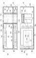
図2は、サーボ制御システム1の上断面図である。また、図3は、図2に示すサーボ制御システム1のI−I線に沿う断面図である。なお、図2及び図3においては、図1で示したヒートシンク68は省略されている。 FIG. 2 is a top sectional view of the servo control system 1. FIG. 3 is a sectional view taken along line II of the servo control system 1 shown in FIG. 2 and 3, the heat sink 68 shown in FIG. 1 is omitted.
各ユニット62〜66の底面はそれぞれ、ボルト80により板状台座67に固定されている。また、両端のユニット62、66は、ボルト及びナットからなる締結部81で板状台座67の側面にも固定されている。さらに、隣接するユニット間は、ボルト及びナットからなる締結部82により固定されている。そして、各ユニット62〜66の上面側は、コントロールボックス底板61bによって密閉されている。 The bottom surfaces of the
昇降圧コンバータユニット62は、昇降圧コンバータを構成するための電気回路及びモジュール等を収容しており、電気的な入力端及び出力端を有する。昇降圧コンバータユニット62の出力端には、例えば蓄電のためのバッテリを接続することができる。この場合には、昇降圧コンバータユニット62は、バッテリの充放電を制御する。 The step-up /
インバータユニット63〜66は、インバータを構成するための電気回路及びモジュール等を収容しており、それぞれ電気的な入力端及び出力端を有する。インバータユニット63〜66の出力端には、例えば、磁石がロータ内部に埋め込まれたIPM(Interior Permanent Magnetic)モータによって構成される交流電動機を接続することができる。この場合には、交流電動機は、インバータユニット63〜66から出力されるPWM(PulseWidth Modulation)制御信号により交流駆動される。 The
DCバス110は、ブスバーからなり、各ユニット62〜66が並べられた方向(第1の方向)に沿って各ユニット62〜66を横断するように設けられている。ブスバーは、細長い金属板からなる。各インバータユニット63〜66の入力端及び昇降圧コンバータユニット62の入力端は各々DCバス110に接続されており、各ユニット62〜66間における直流電力の授受は、DCバス110を介して行われる。昇降圧コンバータユニット62の出力端は、図示しない蓄電池に接続されている。これにより昇降圧コンバータユニット62は、DCバス110と蓄電池との間に配置されることとなるので、蓄電池の充放電の制御を行い、DCバス110の電圧を一定に制御することが可能となる。その結果、各インバータユニット63〜66に安定した電圧をDCバス110より供給することが可能となる。 The DC
次に、各ユニット62〜66の内部構成及び各ユニット62〜66におけるDCバス110との接続を説明する。 Next, the internal configuration of each
図4(a)は、インバータユニット65の一部及びインバータユニット66の内部構成を示す平面図である。また、図4(b)は、インバータユニット65の内部構成を示す側面図である。なお、これらの図においては、インバータユニット65、66の内部構成がわかるようにケースの天板や側板を外した状態を示している。また、インバータユニット63、64の内部構成は、内蔵するインバータ回路の構成を除いて、図4に示すインバータユニット65、66の内部構成と同様である。 FIG. 4A is a plan view showing a part of the
インバータユニット65、66の内部には、インバータの回路を構成するトランジスタを組み込んだインテリジェントパワーモジュール(IPM:Intelligent Power Module)105と、冷却用配管65a、66aとが内蔵されている。IPM105は、配線基板106上に実装されている。冷却用配管65a、66aはそれぞれ、インバータユニット65、66の内側面に沿って二次元状に配設されている。具体的には、冷却用配管65a、66aは、インバータユニット65、66の内部でなるべく長く配設されるように幾重にも折れ曲がった状態で矩形断面の金属容器65b、66bに収容されており、またこの金属容器65b、66bの内側面に接している。金属容器65b、66bの外側面には、図4(a)に示すようにIPM105が接触配置されており、金属容器65b、66bはIPM105からの熱を冷却用配管65a、66aへ伝える。 Inside the
図4(b)を参照すると、インバータユニット65における、インバータユニット66に隣接する側板65dの上辺には、DCバス110を配設するための、矩形切欠き部65eが設けられている。平滑コンデンサ71a、71bは、インバータユニット65の側板65dの内側面に接触配置されており、平滑コンデンサ71a、71bの正側及び負側の端子は、インバータユニット65の側板65d上辺の矩形切欠き部65eに露出している。 Referring to FIG. 4B, a
また、インバータユニット66における、インバータユニット65に隣接する側板66dの上辺にも、DCバス110を配設するための矩形切欠き部66eが設けられている。インバータユニット66における、側板66dに対向する側板66fの内側面に、平滑コンデンサ71a、71bが接触配置されている。 In addition, a
他のインバータユニット63、64における、隣のユニットに隣接する側板の上辺にも、DCバス110を配設するための矩形切欠き部が設けられている(図示せず)。インバータユニット64におけるインバータユニット65に隣接する側板の内側面、及びインバータユニット63におけるインバータユニット64に隣接する側板の内側面には、インバータユニット65、66と同様に、平滑コンデンサが接触配置されている。このようにしてDCバス110は、各ユニットの間に挟まれたインバータユニット63〜65を貫通するように配設されている。さらに、各ユニットの矩形切欠き部と金属容器内は、上蓋としてのコントロールボックス底板61bによって密閉状態を形成している。これにより、各インバータにおいて、防塵及び防水が実現される。 In the
DCバス110は、板状の正極ブスバー70a及び負極ブスバー70bから構成されている。正極ブスバー70aは、横方向(第1の方向)に細長い略直方体形状を有する。負極ブスバー70bは、正極ブスバー70aと接することなく、正極ブスバー70aの上方に配置されており、正極ブスバー70aの上面側を包み込む形状を有し、正極ブスバー70aを覆うように構成される。ここで、正極と負極の配置を逆にしてもよい。 The
正極ブスバー70aは、インバータユニット65、66の平滑コンデンサ71a、71b及びインバータユニット63、64の平滑コンデンサの正側端子に直結するようにボルトによって固定されている。また、負極ブスバー70bは、インバータユニット65、66の平滑コンデンサ71a、71b及びインバータユニット63、64の平滑コンデンサの負側端子に直結するようにボルトによって固定されている。このように、DCバス110は、各インバータユニット63〜66の金属容器に対して非接触状態で、平滑コンデンサに固定されている。 The
IPM105の正極端子(入力端)105aと正極ブスバー70aとは配線により接続されており、負極端子(入力端)105bと負極ブスバー70bとは配線により接続されている。また、IPM105の3相出力端子(出力端)105cはそれぞれ、端子台66cに配線により接続されている。端子台66cは、交流電動機を接続するためのものである。 The positive terminal (input end) 105a of the
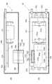
図5(a)は、昇降圧コンバータユニット62の内部構成を示す平面図である。また、図5(b)は、昇降圧コンバータユニット62の内部構成を示す側面図である。なお、これらの図においては、昇降圧コンバータユニット62の内部構成がわかるようにケースの天板や側板を外した状態を示している。 FIG. 5A is a plan view showing the internal configuration of the buck-
昇降圧コンバータユニット62の内部には、昇降圧コンバータの回路を構成するトランジスタを組み込んだIPM103と、リアクトル101と、冷却用配管62aとが内蔵されている。IPM103は、配線基板104上に実装されている。冷却用配管62aは、昇降圧コンバータユニット62の側面に沿って二次元状に配設されている。具体的には、冷却用配管62aは、昇降圧コンバータユニット62の内部でなるべく長く配設されるように幾重にも折れ曲がった状態で矩形断面の金属容器62bに収容されており、またこの金属容器62bの内側面に接している。金属容器62bの外側面には、図5(a)に示すようにリアクトル101及びIPM103が接触配置されており、金属容器62bはリアクトル101及びIPM103からの熱を冷却用配管62aへ伝える。これにより、リアクトル101及びIPM103が冷却される。 Inside the step-up / down
昇降圧コンバータユニット62における、インバータユニット63に隣接する側板62f上辺には、DCバス110を配設するための、矩形切欠き部62fが設けられている。この矩形切欠き部62f及び昇降圧コンバータユニット62の金属容器内は、上蓋としてのコントロールボックス底板61bによって密閉状態を形成している。これにより、昇降圧コンバータにおいて、防塵及び防水が実現される。IPM103の正極端子(入力端)103aと正極ブスバー70aとは配線により接続されており、負極端子(入力端)103bと負極ブスバー70bとは配線により接続されている。また、IPM103の端子103cは、リアクトル101の端子101aと配線により接続されており、リアクトル101の端子101bは、端子台62cと配線により接続されており、IPM103の端子103dは、端子台62dと配線により接続されている。端子台62c、62dは、バッテリを接続するためのものである。 In the step-up / down
次に本実施形態のサーボ制御システム1による効果について説明する。本実施形態のサーボ制御システム1では、昇降圧コンバータユニット62及び複数のインバータユニット63〜66の入力端は、共通のDCバス110に接続される。このため、DCバス110のためのスペースを削減することが可能となり、さらに、メンテナンス性の向上にも寄与する。また、DCバス110を構成するブスバーは、細長い略直方体形状の金属板からなるので、配線接続と比較して、各ユニット62〜66の入力端間を、電流経路を短く、且つ大きな断面積で接続することができる。従って、低抵抗に各ユニット62〜66を接続することが可能となる。 Next, the effect by the servo control system 1 of this embodiment is demonstrated. In the servo control system 1 of this embodiment, the input / output terminals of the step-up / down
また、本実施形態のサーボ制御システム1では、DCバス110は、各ユニット62〜66が配列された方向に沿って、各ユニット62〜66における、隣のユニットに隣接する側板に設けられた矩形状切欠き部に設けられているので、DCバス110を省スペースに配設することが可能となる。 Further, in the servo control system 1 of the present embodiment, the
続いて、本発明に係るサーボ制御システムを種々の作業機械に適用した例について説明する。図6(a)は、サーボ制御システムが適用されたフォークリフトの外観を示す図である。図6(a)に示すように、作業機械としてのフォークリフト1Aは、その車体後方に重りをつけることにより当該車体のバランスをとるように構成された、いわゆるカウンタ式のフォークリフトである。 Next, examples in which the servo control system according to the present invention is applied to various work machines will be described. FIG. 6A is a diagram illustrating an appearance of a forklift to which the servo control system is applied. As shown in FIG. 6 (a), a
フォークリフト1Aは、運転者が乗り込んで着座するための運転席30、フォーク32、車輪34,38等を有して構成されている。フォーク32は、荷物を昇降させるためのものであり、このフォーク32は、運転席30より前方側に設けられている。車輪34,38は、運転席30より前方と後方とに2つずつ配置されており、運転席30よりも後方に配置された車輪38は、操舵用の車輪である。一方、運転席30よりも前方に配置された車輪34は、駆動輪である。 The
図6(b)は、フォークリフト1Aが搭載しているサーボ制御システム1aの概略構成図である。サーボ制御システム1aは、インバータユニット65,66を有しており、インバータユニット65,66は、それぞれバッテリ19からの直流電力により駆動される。インバータユニット65は、直流電力を交流電力に変換して荷役モータ35を駆動する。一方、インバータユニット66は、走行モータ36を駆動する。荷役モータ35は、フォーク32を昇降させるためのモータであり、走行モータ36は、車輪34を駆動するためのモータである。図6(b)に示すように、フォークリフト1Aに本発明のサーボ制御システムを適用する場合には、2個のインバータユニット65,66によりサーボ制御システム1aが構成されることとしてもよい。 FIG. 6B is a schematic configuration diagram of the servo control system 1a mounted on the
図7は、本発明のサーボ制御システムが適用された作業機械の一例として、リフティングマグネット車両1Bの外観を示す斜視図である。図7に示すように、リフティングマグネット車両1Bは、無限軌道を含む走行機構2と、走行機構2の上部に旋回機構3を介して回動自在に搭載された旋回体4とを備えている。旋回体4には、ブーム5と、ブーム5の先端にリンク接続されたアーム6と、アーム6の先端にリンク接続されたリフティングマグネット7とが取り付けられている。リフティングマグネット7は、鋼材などの吊荷Gを磁力により吸着して捕獲するための設備である。ブーム5、アーム6、及びリフティングマグネット7は、それぞれブームシリンダ8、アームシリンダ9、及びバケットシリンダ10によって油圧駆動される。また、旋回体4には、リフティングマグネット7の位置や励磁動作および釈放動作を操作する操作者を収容するための運転室4aや、油圧を発生するためのエンジン11といった動力源が設けられている。エンジン11は、例えばディーゼルエンジンで構成される。 FIG. 7 is a perspective view showing an appearance of a
図8は、リフティングマグネット車両1Bの電気系統や油圧系統といった内部構成を示すブロック図である。なお、図2では、機械的に動力を伝達する系統を二重線で、油圧系統を太い実線で、電気系統を細い実線でそれぞれ示している。また、図9は、図8における蓄電手段120の概略構成を示す図である。 FIG. 8 is a block diagram showing an internal configuration such as an electric system and a hydraulic system of the lifting
図8に示すように、リフティングマグネット車両1Bは電動発電機12および減速機13を備えており、エンジン11及び電動発電機12の回転軸は、共に減速機13の入力軸に接続されることにより互いに連結されている。エンジン11の負荷が大きいときには、電動発電機12が自身の駆動力によりエンジン11の駆動力を補助(アシスト)し、電動発電機12の駆動力が減速機13の出力軸を経てメインポンプ14に伝達される。一方、エンジン11の負荷が小さいときには、エンジン11の駆動力が減速機13を経て電動発電機12に伝達されることにより、電動発電機12が発電を行う。電動発電機12は、例えば、磁石がロータ内部に埋め込まれたIPM(Interior Permanent Magnetic)モータによって構成される。電動発電機12の駆動と発電との切り替えは、リフティングマグネット車両1Bにおける電気系統の駆動制御を行うコントローラ(図示せず)により、エンジン11の負荷等に応じて行われる。 As shown in FIG. 8, the lifting magnet vehicle 1 </ b> B includes a
減速機13の出力軸にはメインポンプ14が接続されており、メインポンプ14には高圧油圧ラインを介して各種の油圧系を制御するためのコントロールバルブ(図示せず)が接続されている。 A
電動発電機12の電気的な端子には、インバータ回路(インバータユニット)65の一端が接続されている。インバータ回路65の他端には、蓄電手段120が接続されている。蓄電手段120は、図9に示すように、例えばDCバス110といった直流配線により構成される一定電圧蓄電部と、昇降圧コンバータ62と、例えば蓄電池であるバッテリ19により構成される変動電圧蓄電部を備えている。即ち、インバータ回路65の入力端は、DCバス110を介して昇降圧コンバータ100の入力端に接続されることとなる。昇降圧コンバータ100の出力端には、バッテリ19が接続されている。 One end of an inverter circuit (inverter unit) 65 is connected to the electrical terminal of the
インバータ回路65は、コントローラからの指令に基づき、電動発電機12の運転制御を行う。すなわち、インバータ回路65が電動発電機12を力行運転させる際には、必要な電力をバッテリ19と昇降圧コンバータ100からDCバス110を介して電動発電機12に供給する。また、電動発電機12を回生運転させる際には、電動発電機12により発電された電力をDCバス110及び昇降圧コンバータ100を介してバッテリ19に充電する。なお、昇降圧コンバータ100の昇圧動作と降圧動作の切替制御は、DCバス電圧値、バッテリ電圧値、及びバッテリ電流値に基づき、コントローラによって行われる。 The
蓄電手段120には、インバータ回路76を介してリフティングマグネット7が接続されている。リフティングマグネット7は、金属物を磁気的に吸着させるための磁力を発生する電磁石を含んでおり、インバータ回路64を介してDCバス110から電力が供給される。インバータ回路64は、コントローラからの指令に基づき、電磁石をオンにする際には、リフティングマグネット7へ要求された電力をDCバス110より供給する。また、電磁石をオフにする場合には、回生された電力をDCバス110に供給する。 A
更に、蓄電手段120には、インバータ回路66を介して旋回用電動機21が接続されている。旋回用電動機21は、旋回体4を旋回させる旋回機構3の動力源である。 Further, the electric motor for turning 21 is connected to the power storage means 120 via the
旋回用電動機21が力行運転を行う際には、旋回用電動機21の回転駆動力の回転力により旋回体4が加減速制御され回転運動を行う。また、旋回体4の慣性回転により、旋回用電動機21に伝達され、回生電力を発生させる。旋回用電動機21は、PWM(Pulse Width Modulation)制御信号によりインバータ回路66によって交流駆動される。旋回用電動機21としては、例えば、磁石埋込型のIPMモータが好適である。 When the turning
更に、蓄電手段120には、インバータ回路63を介して水冷ポンプ22が接続されている。水冷ポンプ22は、インバータ回路63により交流駆動される。 Further, the
なお、蓄電手段120には、インバータ回路63〜66を介して、水冷ポンプ22、リフティングマグネット7、電動発電機12、及び旋回用電動機21が接続されているので、電動発電機12で発電された電力がリフティングマグネット7又は旋回用電動機21に直接的に供給される場合もあり、リフティングマグネット7で回生された電力が電動発電機12又は旋回用電動機21に供給される場合もあり、さらに、旋回用電動機21で回生された電力が電動発電機12又はリフティングマグネット7に供給される場合もある。 The
1…サーボ制御システム、1A…フォークリフト(作業機械)、1B…リフティングマグネット車両(作業機械)、61…コントロールボックス、61b…コントロールボックス底板、62…昇降圧コンバータユニット、63-66…インバータユニット、62f、65d、66d…側板、62e、65e…矩形切欠き部、67…板状台座、70a…正極ブスバー、70b…負極ブスバー、101a、101b、103c、103d…端子、110…DCバス。
DESCRIPTION OF SYMBOLS 1 ... Servo control system, 1A ... Forklift (work machine), 1B ... Lifting magnet vehicle (work machine), 61 ... Control box, 61b ... Control box bottom plate, 62 ... Buck-boost converter unit, 63-66 ... Inverter unit, 62f , 65d, 66d ... side plate, 62e, 65e ... rectangular notch, 67 ... plate-shaped base, 70a ... positive electrode bus bar, 70b ... negative electrode bus bar, 101a, 101b, 103c, 103d ... terminal, 110 ... DC bus.
Claims (10)
Translated fromJapanese前記複数のインバータユニットは、1つの筐体内に固定されており、
前記インバータユニットの入力端は、前記筐体内に配置されたブスバーからなるDCバスに接続されており、
前記DCバスが、前記複数のインバータユニットのうち2つ以上のインバータユニットを貫通して設けられ、前記複数のインバータユニットに対して直接、電気的に結合されている
ことを特徴とするサーボ制御システム。
In a servo control system including an output unit connected to an AC motor, and having a plurality of inverter units that drive the AC motor by converting DC power to AC power.
The plurality of inverter units are fixed in one housing,
The input end of the inverter unit is connected to a DC bus composed of bus barsarranged in the housing,
The servo control system, wherein the DC bus is provided through two or more inverter units among the plurality of inverter units, and is directly electrically coupled to the plurality of inverter units. .
前記インバータユニットにおける、隣のユニットに隣接する側板に切欠き部が設けられており、
前記DCバスは、前記第1の方向に沿って前記切欠き部に設けられている
ことを特徴とする請求項1に記載のサーボ制御システム。The inverter unit has a rectangular parallelepiped appearance and is arranged and fixed in the first direction,
In the inverter unit, a side plate adjacent to the adjacent unit is provided with a notch,
The servo control system according to claim 1, wherein the DC bus is provided in the notch along the first direction.
前記昇降圧コンバータユニットは、前記筐体内に固定されており、
前記昇降圧コンバータユニットの入力端は、前記DCバスに接続されていることを特徴とする請求項1または2に記載のサーボ制御システム。The output end is connected to a battery, and further comprises a step-up / down converter unit for charging and discharging the battery,
The step-up / down converter unit is fixed in the housing,
The servo control system according to claim 1, wherein an input end of the step-up / down converter unit is connected to the DC bus.
前記昇降圧コンバータユニットにおける、隣のユニットに隣接する側板に切欠き部が設けられており、
前記DCバスは、前記第1の方向に沿って前記切欠き部に設けられている
ことを特徴とする請求項3に記載のサーボ制御システム。The step-up / step-down converter unit has a rectangular parallelepiped appearance, and is fixed side by side with the inverter unit in a first direction,
In the step-up / down converter unit, a side plate adjacent to the adjacent unit is provided with a notch,
The servo control system according to claim 3, wherein the DC bus is provided in the notch along the first direction.
2つの他のユニットの間に配置される1のユニットにおいて、前記DCバスは、前記1のユニットを貫通して設けられている
ことを特徴とする請求項3または4に記載のサーボ制御システム。Comprising three or more units comprising the step-up / down converter unit or the inverter unit;
The servo control system according to claim 3 or 4, wherein, in one unit arranged between two other units, the DC bus is provided so as to penetrate the one unit.
前記正の極及び負の極の一方の極は、他方の極を覆うように構成される
ことを特徴とする請求項1乃至5のいずれか1項に記載のサーボ制御システム。The DC bus is composed of a positive pole and a negative pole,
The servo control system according to claim 1, wherein one of the positive pole and the negative pole is configured to cover the other pole.
前記DCバスは、前記平滑コンデンサに直結していることを特徴とする請求項1乃至8のいずれか1項に記載のサーボ制御システム。The inverter unit includes a smoothing capacitor,
The servo control system according to any one of claims 1 to 8, wherein the DC bus is directly connected to the smoothing capacitor.
前記複数のインバータユニットは、1つの筐体内に固定されており、
前記インバータユニットの入力端は、前記筐体内に配置されたブスバーからなるDCバスに接続されており、
前記DCバスが、前記複数のインバータユニットのうち2つ以上のインバータユニットを貫通して設けられ、前記複数のインバータユニットに対して直接、電気的に結合されている
ことを特徴とする作業機械。
The output end is connected to an AC motor, and includes a servo control system including a plurality of inverter units that drive the AC motor by converting DC power to AC power.
The plurality of inverter units are fixed in one housing,
The input end of the inverter unit is connected to a DC bus composed of bus barsarranged in the housing,
The working machine, wherein the DC bus is provided through two or more inverter units among the plurality of inverter units, and is directly electrically coupled to the plurality of inverter units .
Priority Applications (1)
| Application Number | Priority Date | Filing Date | Title |
|---|---|---|---|
| JP2008295864AJP5306786B2 (en) | 2008-11-19 | 2008-11-19 | Servo control system and work machine |
Applications Claiming Priority (1)
| Application Number | Priority Date | Filing Date | Title |
|---|---|---|---|
| JP2008295864AJP5306786B2 (en) | 2008-11-19 | 2008-11-19 | Servo control system and work machine |
Publications (2)
| Publication Number | Publication Date |
|---|---|
| JP2010124604A JP2010124604A (en) | 2010-06-03 |
| JP5306786B2true JP5306786B2 (en) | 2013-10-02 |
Family
ID=42325438
Family Applications (1)
| Application Number | Title | Priority Date | Filing Date |
|---|---|---|---|
| JP2008295864AExpired - Fee RelatedJP5306786B2 (en) | 2008-11-19 | 2008-11-19 | Servo control system and work machine |
Country Status (1)
| Country | Link |
|---|---|
| JP (1) | JP5306786B2 (en) |
Families Citing this family (7)
| Publication number | Priority date | Publication date | Assignee | Title |
|---|---|---|---|---|
| DE19926472C2 (en) | 1999-06-10 | 2001-11-15 | Call A Bike Mobilitaetssysteme | Method of transmitting a code |
| CA2412184C (en) | 2000-07-10 | 2015-04-07 | Paypal, Inc. | System and method for verifying a financial instrument |
| JP2013031260A (en)* | 2011-07-27 | 2013-02-07 | Mitsubishi Electric Corp | Motor control device |
| CN102916601A (en)* | 2012-10-22 | 2013-02-06 | 江苏兆伏新能源有限公司 | Photovoltaic inversion unit and triphase photovoltaic inversion device |
| US20150134302A1 (en) | 2013-11-14 | 2015-05-14 | Jatin Chhugani | 3-dimensional digital garment creation from planar garment photographs |
| US10366439B2 (en) | 2013-12-27 | 2019-07-30 | Ebay Inc. | Regional item reccomendations |
| US20160092956A1 (en) | 2014-09-30 | 2016-03-31 | Jonathan Su | Garment size mapping |
Family Cites Families (6)
| Publication number | Priority date | Publication date | Assignee | Title |
|---|---|---|---|---|
| JPH07274353A (en)* | 1994-03-24 | 1995-10-20 | Yazaki Corp | Electric connection box and manufacturing method thereof |
| JP2001061282A (en)* | 1999-08-19 | 2001-03-06 | Meidensha Corp | Inverter device |
| JP2004096832A (en)* | 2002-08-29 | 2004-03-25 | Toshiba Corp | Liquid-cooled power converter |
| JP2007129838A (en)* | 2005-11-04 | 2007-05-24 | Fuji Electric Systems Co Ltd | Power converter |
| JP2007155586A (en)* | 2005-12-07 | 2007-06-21 | Sumitomo Heavy Ind Ltd | Working machine and method for starting operation of working machine |
| JP2007220976A (en)* | 2006-02-17 | 2007-08-30 | Toyota Motor Corp | Semiconductor module and drive device for hybrid vehicle including the same |
- 2008
- 2008-11-19JPJP2008295864Apatent/JP5306786B2/ennot_activeExpired - Fee Related
Also Published As
| Publication number | Publication date |
|---|---|
| JP2010124604A (en) | 2010-06-03 |
Similar Documents
| Publication | Publication Date | Title |
|---|---|---|
| JP5306786B2 (en) | Servo control system and work machine | |
| KR101482481B1 (en) | Working machine | |
| JP5872025B2 (en) | Industrial machinery | |
| CN101990505B (en) | Operating machine | |
| EP2511220B1 (en) | Construction machine | |
| JP2008044408A (en) | Battery holding structure of battery-driven construction machine | |
| JP2004169465A (en) | Equipment arrangement structure of hybrid construction machinery | |
| JP2010202135A (en) | Working machine | |
| JP5313000B2 (en) | Construction machinery | |
| JP2004169466A (en) | Equipment arrangement structure of construction machinery | |
| JP2015142472A (en) | Busbar structure, power conversion device and work machine | |
| JP5583917B2 (en) | Hybrid construction machine | |
| JP6213974B2 (en) | Work machine | |
| JP5312999B2 (en) | Hybrid construction machine | |
| JP6444038B2 (en) | Excavator | |
| JP5236433B2 (en) | Hybrid construction machine | |
| JP5329187B2 (en) | Hybrid construction machine | |
| JP2014007786A (en) | Power conversion device for working vehicle | |
| JP2015198483A (en) | Bi-directional dc/dc converter for industrial vehicle | |
| JP5356067B2 (en) | Hybrid construction machine | |
| JP5178548B2 (en) | Hybrid construction machine | |
| JP2010226783A (en) | Servo control system | |
| JP6021737B2 (en) | Power storage device and work machine | |
| JP2016010191A (en) | Motor driving device for industrial vehicle and industrial vehicle using the same | |
| JP2010171080A (en) | Servo control system, and operating machine |
Legal Events
| Date | Code | Title | Description |
|---|---|---|---|
| A621 | Written request for application examination | Free format text:JAPANESE INTERMEDIATE CODE: A621 Effective date:20110214 | |
| A977 | Report on retrieval | Free format text:JAPANESE INTERMEDIATE CODE: A971007 Effective date:20120914 | |
| A131 | Notification of reasons for refusal | Free format text:JAPANESE INTERMEDIATE CODE: A131 Effective date:20121002 | |
| A521 | Request for written amendment filed | Free format text:JAPANESE INTERMEDIATE CODE: A523 Effective date:20121129 | |
| TRDD | Decision of grant or rejection written | ||
| A01 | Written decision to grant a patent or to grant a registration (utility model) | Free format text:JAPANESE INTERMEDIATE CODE: A01 Effective date:20130625 | |
| A61 | First payment of annual fees (during grant procedure) | Free format text:JAPANESE INTERMEDIATE CODE: A61 Effective date:20130626 | |
| R150 | Certificate of patent or registration of utility model | Free format text:JAPANESE INTERMEDIATE CODE: R150 Ref document number:5306786 Country of ref document:JP Free format text:JAPANESE INTERMEDIATE CODE: R150 | |
| LAPS | Cancellation because of no payment of annual fees |