JP5306751B2 - Vapor compression refrigerator - Google Patents
Vapor compression refrigeratorDownload PDFInfo
- Publication number
- JP5306751B2 JP5306751B2JP2008235329AJP2008235329AJP5306751B2JP 5306751 B2JP5306751 B2JP 5306751B2JP 2008235329 AJP2008235329 AJP 2008235329AJP 2008235329 AJP2008235329 AJP 2008235329AJP 5306751 B2JP5306751 B2JP 5306751B2
- Authority
- JP
- Japan
- Prior art keywords
- condenser
- ejector
- compressor
- tank
- cooling water
- Prior art date
- Legal status (The legal status is an assumption and is not a legal conclusion. Google has not performed a legal analysis and makes no representation as to the accuracy of the status listed.)
- Expired - Fee Related
Links
Images
Landscapes
- Applications Or Details Of Rotary Compressors (AREA)
- Vaporization, Distillation, Condensation, Sublimation, And Cold Traps (AREA)
Description
Translated fromJapaneseこの発明は蒸気圧縮式冷凍機に関し、特に、従来は廃棄されていた温排水からの再蒸発蒸気を利用する蒸気圧縮式冷凍機に関する。 The present invention relates to a vapor compression refrigerator, and more particularly, to a vapor compression refrigerator that uses re-evaporated vapor from warm wastewater that has been conventionally discarded.
冷凍機は、発電機2と吸収冷凍機10を組み合わせて、発電機2をガスエンジン3で駆動すると共に、ガスエンジン3の排ガスEGと、ガスエンジン3を冷却する冷却水EWを、吸収冷凍機10の熱源として用いるもので、ガスエンジン3の排熱を有効に活用することができるものである。 The refrigerator combines the
上記従来の冷凍機では、各種工場やプラントの現場において、ほとんど廃棄されていた比較的温度の低い温排水を有効に活用することができない問題があった。温度の低い温排水であってもいまだ熱エネルギーを保有しており、その量が多くなれば保有している熱エネルギーも大きなものとなり、有効に活用することによって省エネルギーを図ることができる。
解決しようとする課題は、温排水の熱エネルギーを有効に活用することのできる蒸気圧縮式冷凍機を得ることである。 The problem to be solved is to obtain a vapor compression refrigerator that can effectively use the thermal energy of hot waste water.
本発明は、圧縮機と凝縮器と膨張弁と蒸発器からなるものにおいて、圧縮機をスクリュー式のコンプレッサとすると共に、当該スクリュー式コンプレッサの入口側に比較的低温度の温排水源を接続して、当該温排水源を、温排水を一旦溜め置く温排水タンクとして、当該温排水タンク内で温排水から再蒸発した蒸気をスクリュー式コンプレッサで圧縮すると共に、凝縮器にエゼクター式真空ポンプを接続して、当該エゼクター式真空ポンプを、エゼクターとタンクと循環ポンプで構成したものである。The present invention comprises a compressor, a condenser, an expansion valve, and an evaporator. The compressor is a screw-type compressor, and a relatively low-temperature hot waste water source is connected to the inlet side of the screw-type compressor. Then, thehot drainage source is used as a hot drainage tank that temporarily stores hot drainage, and the vapor re-evaporated from the hot drainage in the hot drainage tank is compressed by a screw compressor, and an ejector vacuum pump is connected to the condenser. The ejector vacuum pump is composed of an ejector, a tank, and a circulation pump .
本発明の蒸気圧縮式冷凍機は、圧縮機を比較的低温度の温排水源と接続して、この温排水の再蒸発蒸気を圧縮機で圧縮することによって、温排水の熱エネルギーを有効に活用することのできる蒸気圧縮式冷凍機を得ることができる。 The vapor compression refrigerator of the present invention effectively connects thermal energy of hot wastewater by connecting the compressor to a relatively low temperature hot wastewater source and compressing the re-evaporated steam of the warm wastewater with the compressor. A vapor compression refrigerator that can be utilized can be obtained.
本発明は、圧縮機を温排水源と接続するものであるが、温排水源としては、温排水を一旦溜め置く温排水タンクとして、この温排水タンク内で温排水から再蒸発した蒸気を圧縮機で圧縮することが好適である。 In the present invention, the compressor is connected to a warm drainage source. As the warm drainage source, as a warm drainage tank in which the warm drainage is temporarily stored, the vapor re-evaporated from the warm drainage is compressed in the warm drainage tank. It is preferable to compress with a machine.
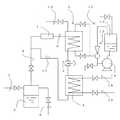
図1において、圧縮機1と凝縮器2と膨張弁3と蒸発器4、及び、温排水源としての温排水タンク5とで蒸気圧縮式冷凍機を構成する。 In FIG. 1, a
圧縮機1はスクリュー式のコンプレッサを用いて、コンプレッサの入口と温排水タンク5の上部を管路6で接続する。温排水タンク5の左側面に温排水供給管7を接続する。温排水タンク5の右側面にタンク5内の余剰水を排除する余剰水排出管8を接続する。The
圧縮機1の出口側に管路9を介して凝縮器2と接続する。凝縮器2の内部に管路9がコイル状に配置されて下方の膨張弁3と連通する。凝縮器2には、冷却水供給管10を接続すると共に、エゼクター式真空ポンプ11を接続する。エゼクター式真空ポンプ11は、エゼクター12とタンク13と循環ポンプ14とで構成され、タンク13内の冷却水を循環ポンプ14でエゼクター12へ供給することによって、エゼクター12で真空吸引力を発生して、凝縮器2の上部と下部から凝縮器2内を吸引して大気圧以下の真空状態に維持し、凝縮器2内で管路9から供給される圧縮蒸気を冷却水が蒸発することによる蒸発潜熱でもって気化冷却することができるものである。 The
凝縮器2の下方に膨張弁3を介して蒸発器4を接続する。蒸発器4には、冷媒供給管15と排出管16をそれぞれコイル状に接続する。凝縮器2で冷却された圧縮蒸気は低温水となって膨張弁3から蒸発器4内へ噴射されることで断熱膨張すると共に、冷媒管15,16内の冷媒の熱を奪って蒸発することで、冷媒を所定の低温まで冷却することができるものである。蒸発器4内で蒸発した蒸気は、管路17をとおって再度、圧縮機1へ吸引される。 An evaporator 4 is connected below the
温排水供給管7から温排水タンク5内へ供給された温排水の一部が再度蒸発してタンク5の上部に溜まり、この再蒸発蒸気がスクリュー式コンプレッサ1に吸引されて高圧高温の蒸気となり、管路9をとおって凝縮器2へ送られて冷却されて高圧低温の低温水となって、膨張弁3から蒸発器4へ供給されて冷媒を冷却するための熱源となる。 A part of the warm drainage supplied from the warm
スクリュー式コンプレッサ1を比較的低温度の温排水タンク5と接続して、この温排水の再蒸発蒸気をスクリュー式コンプレッサ1で圧縮することによって、温排水の保有する熱エネルギーを有効に活用することができる。 By connecting the screw-
1 スクリュー式コンプレッサ
2 凝縮器
3 膨張弁
4 蒸発器
5 温排水タンク
7 温排水供給管
10 冷却水供給管
11 エゼクター式真空ポンプ
12 エゼクター
13 タンク
14 循環ポンプ
15 冷媒供給管
16 冷媒排出管
DESCRIPTION OF
Claims (1)
Translated fromJapanese前記圧縮機をスクリュー式のコンプレッサとし、
当該スクリュー式コンプレッサの入口側に比較的低温度の温排水源を接続し、
当該温排水源を、温排水を一旦溜め置く温排水タンクとし、
当該温排水タンク内で温排水から再蒸発した蒸気を前記スクリュー式コンプレッサで圧縮し、
前記前記スクリュー式コンプレッサの出口に管路を介して前記凝縮器を接続し、
前記凝縮器の内部に前記管路をコイル状に配置して、前記管路を前記膨張弁と連通させ、
エゼクター式真空ポンプを、エゼクターとタンクと循環ポンプとで構成し、
前記凝縮器に冷却水供給管を接続すると共に、前記エゼクタの吸引口を接続し、
前記タンク内の冷却水を前記循環ポンプで前記エゼクターへ供給することにより前記エゼクターで真空吸引力を発生させて、前記エゼクターにより前記凝縮器内を吸引して大気圧以下の真空状態に維持し、
前記凝縮器内で前記管路から供給される圧縮蒸気を、前記冷却水供給管からの冷却水が蒸発することによる蒸発潜熱でもって気化冷却し、
前記気化冷却した蒸気を用いて、前記膨張弁に接続された前記蒸発器において冷媒を冷却することを特徴とする蒸気圧縮式冷凍機。In what consists of a compressor, a condenser, an expansion valve and an evaporator,
The compressor is a screw type compressor,
Connect a relatively low temperature hot drainage source to the inlet side of the screw compressor,
The thermal drainage source is a warm drainage tank that temporarily stores hot drainage,
The vapor re-evaporated from the hot wastewater in the hot wastewater tank is compressedby the screw compressor,
Connecting the condenser via a conduit to the outlet of the screw compressor;
Arranging the pipe line inside the condenser in a coil shape, communicating the pipe line with the expansion valve,
Thed Zekuta vacuum pump, constituted by the ejector and the tank and the circulationpump,
A cooling water supply pipe is connected to the condenser, and a suction port of theejector is connected.
By supplying cooling water in the tank to the ejector with the circulation pump, a vacuum suction force is generated by the ejector, and the inside of the condenser is sucked by the ejector and maintained in a vacuum state below atmospheric pressure,
The compressed steam supplied from the pipe line in the condenser is vaporized and cooled with latent heat of evaporation caused by evaporation of the cooling water from the cooling water supply pipe,
A vapor compression refrigeratorthat uses the vaporized and cooled steam to cool a refrigerant in the evaporator connected to the expansion valve .
Priority Applications (1)
| Application Number | Priority Date | Filing Date | Title |
|---|---|---|---|
| JP2008235329AJP5306751B2 (en) | 2008-09-12 | 2008-09-12 | Vapor compression refrigerator |
Applications Claiming Priority (1)
| Application Number | Priority Date | Filing Date | Title |
|---|---|---|---|
| JP2008235329AJP5306751B2 (en) | 2008-09-12 | 2008-09-12 | Vapor compression refrigerator |
Publications (2)
| Publication Number | Publication Date |
|---|---|
| JP2010065984A JP2010065984A (en) | 2010-03-25 |
| JP5306751B2true JP5306751B2 (en) | 2013-10-02 |
Family
ID=42191710
Family Applications (1)
| Application Number | Title | Priority Date | Filing Date |
|---|---|---|---|
| JP2008235329AExpired - Fee RelatedJP5306751B2 (en) | 2008-09-12 | 2008-09-12 | Vapor compression refrigerator |
Country Status (1)
| Country | Link |
|---|---|
| JP (1) | JP5306751B2 (en) |
Family Cites Families (10)
| Publication number | Priority date | Publication date | Assignee | Title |
|---|---|---|---|---|
| JPS60147067A (en)* | 1984-01-10 | 1985-08-02 | 協和醗酵工業株式会社 | Heat pump |
| JPS61138057A (en)* | 1984-12-10 | 1986-06-25 | 株式会社東芝 | Heat pump device |
| JP3510010B2 (en)* | 1995-07-14 | 2004-03-22 | 株式会社テイエルブイ | Vacuum steam heating device |
| US5603227A (en)* | 1995-11-13 | 1997-02-18 | Carrier Corporation | Back pressure control for improved system operative efficiency |
| JPWO2002077546A1 (en)* | 2001-03-14 | 2004-07-15 | 積水化学工業株式会社 | Heat pump and heat pump system |
| JP2003074994A (en)* | 2001-08-28 | 2003-03-12 | Calsonic Kansei Corp | Radiator |
| JP4052867B2 (en)* | 2002-04-22 | 2008-02-27 | 三建設備工業株式会社 | Water refrigerant natural circulation cooling system with water vapor compression refrigerator |
| JP4133355B2 (en)* | 2003-01-15 | 2008-08-13 | 株式会社テイエルブイ | Steam power generator |
| JP2006292229A (en)* | 2005-04-08 | 2006-10-26 | Mayekawa Mfg Co Ltd | Co2 refrigeration cycle device and supercritical refrigeration operation method therefor |
| JP4457138B2 (en)* | 2007-09-28 | 2010-04-28 | 株式会社日立製作所 | Compressor and heat pump system |
- 2008
- 2008-09-12JPJP2008235329Apatent/JP5306751B2/ennot_activeExpired - Fee Related
Also Published As
| Publication number | Publication date |
|---|---|
| JP2010065984A (en) | 2010-03-25 |
Similar Documents
| Publication | Publication Date | Title |
|---|---|---|
| CN105174330B (en) | The apparatus and method for preparing distilled water with negative pressure low-temperature boiling are driven based on heat pump | |
| WO2013164653A1 (en) | Method for cooling air and apparatus to perform the method | |
| CN205843115U (en) | A kind of carbon dioxide heat pump device with heating function | |
| KR20200075602A (en) | Carbon dioxide pressurization system for carbon dioxide capture and storage | |
| JP2014190586A (en) | Ejector type refrigeration cycle device | |
| CN208832629U (en) | A kind of low-temperature cold water unit | |
| CN201173639Y (en) | A refrigeration device that produces a cold source below the freezing point of the main refrigerant | |
| JP5312884B2 (en) | Vapor compression refrigerator | |
| JP5306751B2 (en) | Vapor compression refrigerator | |
| JP2013040726A (en) | Device with heater | |
| JP5306750B2 (en) | Vapor compression refrigerator | |
| JP2012202369A (en) | Heat pump integrated with evaporator and rankine cycle system | |
| JP2012202665A (en) | Heat-driven heat pump cycle device and refrigerant circulating pump used for the same | |
| JP2013217512A (en) | Engine driven heat pump air conditioner | |
| CN102589190A (en) | Refrigeration method and special equipment without using compressor | |
| CN211120095U (en) | Dual Evaporator Refrigeration System with Dual Ejector Efficiency | |
| CN202371963U (en) | Freon calandria type refrigerating and defrosting system of refrigeration house | |
| CN113974197A (en) | A Tobacco Vacuum Reconditioning Machine with a Compound Vacuum Device | |
| CN106592696A (en) | Fuel cell based air water-taking device | |
| CN112717448A (en) | Low boiling point working medium compression secondary steam device | |
| CN207299605U (en) | A kind of heated type refrigerating circulatory device | |
| CN201706769U (en) | Lithium bromide central air conditioner for fully recycling vaporization heat | |
| CN204630135U (en) | A kind of cooling cycle system | |
| KR101581924B1 (en) | Green water dispenser equipped with hot-water supply part | |
| CN116835702B (en) | Seawater desalination system and method based on high temperature of seawater of nuclear power plant |
Legal Events
| Date | Code | Title | Description |
|---|---|---|---|
| A621 | Written request for application examination | Free format text:JAPANESE INTERMEDIATE CODE: A621 Effective date:20110801 | |
| A131 | Notification of reasons for refusal | Free format text:JAPANESE INTERMEDIATE CODE: A131 Effective date:20121023 | |
| A521 | Request for written amendment filed | Free format text:JAPANESE INTERMEDIATE CODE: A523 Effective date:20121212 | |
| A131 | Notification of reasons for refusal | Free format text:JAPANESE INTERMEDIATE CODE: A131 Effective date:20130402 | |
| A521 | Request for written amendment filed | Free format text:JAPANESE INTERMEDIATE CODE: A523 Effective date:20130603 | |
| TRDD | Decision of grant or rejection written | ||
| A01 | Written decision to grant a patent or to grant a registration (utility model) | Free format text:JAPANESE INTERMEDIATE CODE: A01 Effective date:20130625 | |
| A61 | First payment of annual fees (during grant procedure) | Free format text:JAPANESE INTERMEDIATE CODE: A61 Effective date:20130626 | |
| R150 | Certificate of patent or registration of utility model | Free format text:JAPANESE INTERMEDIATE CODE: R150 Ref document number:5306751 Country of ref document:JP Free format text:JAPANESE INTERMEDIATE CODE: R150 | |
| LAPS | Cancellation because of no payment of annual fees |