JP5306416B2 - Terminal apparatus, wireless communication method, base station apparatus, and transmission / reception method - Google Patents
Terminal apparatus, wireless communication method, base station apparatus, and transmission / reception methodDownload PDFInfo
- Publication number
- JP5306416B2 JP5306416B2JP2011123416AJP2011123416AJP5306416B2JP 5306416 B2JP5306416 B2JP 5306416B2JP 2011123416 AJP2011123416 AJP 2011123416AJP 2011123416 AJP2011123416 AJP 2011123416AJP 5306416 B2JP5306416 B2JP 5306416B2
- Authority
- JP
- Japan
- Prior art keywords
- block
- base station
- blocks
- cqi
- unit
- Prior art date
- Legal status (The legal status is an assumption and is not a legal conclusion. Google has not performed a legal analysis and makes no representation as to the accuracy of the status listed.)
- Expired - Lifetime
Links
Images


Landscapes
- Mobile Radio Communication Systems (AREA)
Abstract
Description
Translated fromJapanese本発明は、マルチキャリア伝送における端末装置、無線通信方法、基地局装置及び送受信方法に関するものであり、例えば、OFDM(Orthogonal Frequency Division Multiplex)通信システムに適用して好適なものである。The present invention relates to aterminal device, a wireless communication method, a base station device, and a transmission / reception method in multicarrier transmission, and is suitable for application to, for example, an OFDM (Orthogonal Frequency Division Multiplex) communication system.
従来、W−CDMA(Wideband-Code Division Multiple Access)移動通信システムでは、高速大容量な下りチャネルを複数の通信端末装置が共有し、基地局装置から通信端末装置にパケットデータを高速伝送する下り高速パケット伝送方式(HSDPA:High Speed Downlink Packet Access)が開発されている。 Conventionally, in a W-CDMA (Wideband-Code Division Multiple Access) mobile communication system, a plurality of communication terminal apparatuses share a high-speed and large-capacity downlink channel, and high-speed downlink transmission that transmits packet data from the base station apparatus to the communication terminal apparatus at high speed. A packet transmission system (HSDPA: High Speed Downlink Packet Access) has been developed.
ここで、W−CDMAシステムにおけるHSDPAについて簡単に説明する。通信端末装置が受信CIR(Carrier to Interference Ratio)を測定し、測定したCIRに基づいて下り回線状態を示す情報(例えば、CQI:Channel Quality of Indicator)を基地局装置に報告する。基地局装置は各通信端末装置から報告されたCQIに基づいて、パケットデータを送信する通信端末装置(送信先装置)を決定する。これをスケジューリングという。また、送信先装置に送信するパケットデータをどのような変調方式及び符号化率(MCS:Modulation and Coding Scheme)で処理するかをCQIが示す下り回線状態に基づいて決定する。これをMCS割り当てという。基地局装置は、決定した送信先装置に決定したMCSでパケットデータを送信する。 Here, HSDPA in the W-CDMA system will be briefly described. The communication terminal apparatus measures a received CIR (Carrier to Interference Ratio), and reports information indicating a downlink state (for example, CQI: Channel Quality of Indicator) to the base station apparatus based on the measured CIR. The base station apparatus determines a communication terminal apparatus (transmission destination apparatus) that transmits packet data based on the CQI reported from each communication terminal apparatus. This is called scheduling. In addition, based on the downlink state indicated by the CQI, what modulation method and coding rate (MCS: Modulation and Coding Scheme) the packet data to be transmitted to the transmission destination device is to be processed is determined. This is called MCS allocation. The base station apparatus transmits packet data with the determined MCS to the determined transmission destination apparatus.
MCS割り当ての具体例として、図14のようなフェージング変動があった場合を考える。図14は、フェージングによる受信電力の時間変動を示す図である。この図において、横軸を時間、縦軸を受信電力とし、t1で受信電力が最大となり、t2で受信電力が最小なったとする。t1では、伝搬路が良好な状態であると判断し、高いMCSレベル(例えば、16QAM、符号化率3/4)を割り当てる。一方、t2では、伝搬路が劣悪な状態であると判断し、低いMCSレベル(例えば、QPSK、符号化率1/4)を割り当てる。 As a specific example of MCS assignment, consider the case where there is a fading fluctuation as shown in FIG. FIG. 14 is a diagram illustrating temporal variation in received power due to fading. In this figure, it is assumed that the horizontal axis is time, the vertical axis is reception power, the reception power is maximum at t1, and the reception power is minimum at t2. At t1, it is determined that the propagation path is in a good state, and a high MCS level (for example, 16QAM,
このように、割り当てられるMCSのレベルが高い通信端末装置を送信先として決定すれば、短時間で多くのデータを送信することができるので、システムのスループットを向上させることができる。 In this way, if a communication terminal device having a high assigned MCS level is determined as a transmission destination, a large amount of data can be transmitted in a short time, so that the throughput of the system can be improved.
また、従来のW−CDMAシステムでは、送信電力を制御することにより、ビット当たりの受信品質を保つが、HSDPAでは、上述したようにMCSを制御することにより、ビット当たりの受信品質を保つことができる。 In the conventional W-CDMA system, the reception quality per bit is maintained by controlling the transmission power. In HSDPA, the reception quality per bit is maintained by controlling the MCS as described above. it can.
上述したHSDPAは、W−CDMAシステムに適用することを前提とした技術であるが、次世代の通信方式として有望なOFDM(Orthogonal Frequency Division Multiplexing)通信端末装置にHSDPA技術を適用することが検討されている。OFDMにHSDPA技術を適用した例として、以下のものがある。 The above-described HSDPA is a technology premised on being applied to a W-CDMA system. However, it is considered to apply the HSDPA technology to an OFDM (Orthogonal Frequency Division Multiplexing) communication terminal device that is promising as a next-generation communication method. ing. Examples of applying HSDPA technology to OFDM include the following.
(従来例1)
通信端末装置は、全サブキャリアの受信CIRを測定し、測定したCIRに基づいてCQIを基地局装置に報告する。基地局装置は各通信端末装置から報告されたCQIに基づいて、スケジューリング、MCS割り当てを行い、全サブキャリアを使って送信する。または、全周波数にわたるサブキャリアを均等に分散して送信する。また、周辺セルに与える干渉を低減するため、使用しないサブキャリアを用意する。周辺セルのユーザ数が多くなってきた場合、使用しないサブキャリアを増加させることによって、周辺セルに与える多くの干渉を防ぐことができ、システムスループットを向上させることができる。(Conventional example 1)
The communication terminal apparatus measures the reception CIR of all subcarriers and reports the CQI to the base station apparatus based on the measured CIR. The base station apparatus performs scheduling and MCS allocation based on the CQI reported from each communication terminal apparatus, and transmits using all subcarriers. Alternatively, subcarriers over all frequencies are transmitted evenly distributed. Also, unused subcarriers are prepared to reduce interference with neighboring cells. When the number of users in the neighboring cell increases, by increasing the number of subcarriers that are not used, a lot of interference given to the neighboring cell can be prevented, and the system throughput can be improved.
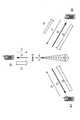
図15は、従来例1における周波数の割り当て方法を示す図である。ここでは、一例として、ユーザ数を2とし、UE1とUE2に周波数を割り当てる様子を示す。システムで使用する周波数帯域を5MHzとし、サブキャリア数を512とする。従来例1は、図15に示すように、全サブキャリアをUE1、UE2及び割り当てないサブキャリア(割り当て対象なし)で順番に割り当てる。割り当て対象なしのサブキャリアは、ユーザ1とユーザ2の間に割り当てられる。 FIG. 15 is a diagram showing a frequency allocation method in the first conventional example. Here, as an example, it is assumed that the number of users is 2, and a frequency is allocated to UE1 and UE2. The frequency band used in the system is 5 MHz, and the number of subcarriers is 512. As shown in FIG. 15, Conventional Example 1 assigns all subcarriers in order by UE1, UE2 and unassigned subcarriers (no assignment target). Subcarriers not to be allocated are allocated between
(従来例2)
従来例2では、周波数(サブキャリア)によるフェージング変動の違いがMCS割り当てに反映されるように、次のような方法でスケジューリングとMCS割り当てを行っている。通信端末装置は全サブキャリアの受信CIRを測定し、測定したCIRに基づいてCQIを基地局装置に報告する。基地局装置は各通信端末装置から報告されたCQIに基づいて、送信する通信端末装置(複数でも可)とMCSとサブキャリアを決定する。(Conventional example 2)
In Conventional Example 2, scheduling and MCS allocation are performed by the following method so that the difference in fading fluctuation due to frequency (subcarrier) is reflected in MCS allocation. The communication terminal apparatus measures the received CIR of all subcarriers and reports the CQI to the base station apparatus based on the measured CIR. Based on the CQI reported from each communication terminal apparatus, the base station apparatus determines the communication terminal apparatus (s) to be transmitted, MCS, and subcarrier.
次の送信回からは通信端末装置は割り当てられたサブキャリアのCIRに基づいてCQIを生成し、このCQIを基地局装置に報告する。基地局装置はその通信端末装置に対して、次も同じサブキャリアを使えばより正確なCQIによるMCS割り当てを行うことができる。この方法を概念的に示したのが図16である。 From the next transmission time, the communication terminal apparatus generates CQI based on the CIR of the assigned subcarrier, and reports this CQI to the base station apparatus. The base station apparatus can perform more accurate MCS allocation by CQI if the same subcarrier is used next time for the communication terminal apparatus. FIG. 16 conceptually shows this method.
図16は、従来例2における通信方法を概念的に示した図である。この図では、NodeB(基地局装置)とUE1〜3(通信端末装置1〜3)が通信している場合を想定する。まず、UE1〜3が初回の送信において、全サブキャリアについてCQIをNodeBに送信する(図中(1))。NodeBは、送信されたCQIに基づいてスケジューリングを行い、データの送信を開始する(図中(2))。UE1〜3は、次の送信回のため、割り当てられた周波数(サブキャリア)についてCQIをNodeBに送信する(図中(3))。NodeBは、次の送信回のスケジューリングを行い、UE3にデータの送信を行う。(図中(4))この例では、図中(2)において、NodeBはUE1〜3に対して、図17に示すように、周波数(サブキャリア)を割当てているものとする。 FIG. 16 is a diagram conceptually illustrating a communication method in the second conventional example. In this figure, the case where NodeB (base station apparatus) and UE1-3 (communication terminal devices 1-3) are communicating is assumed. First, UE1 to UE3 transmit CQIs to NodeBs for all subcarriers in the first transmission ((1) in the figure). The NodeB performs scheduling based on the transmitted CQI and starts data transmission ((2) in the figure). The
図17は、従来例2における周波数の割り当て方法を示す図である。ここでは、図15と異なる部分についてのみ説明し、ユーザ数を3とし、UE1〜3に周波数を割り当てる様子を示す。従来例2では、隣接するサブキャリアをまとめてユーザに割り当てるようにし、隣接セルへの干渉を軽減するために割り当てないサブキャリア(割り当て対象なし)を設けるようにする。 FIG. 17 is a diagram illustrating a frequency allocation method in the second conventional example. Here, only a different part from FIG. 15 is demonstrated, the number of users is set to 3, and a mode that a frequency is allocated to UE1-3 is shown. In Conventional Example 2, adjacent subcarriers are collectively allocated to a user, and subcarriers that are not allocated (no allocation target) are provided in order to reduce interference with adjacent cells.
しかしながら、上記従来例1及び従来例2では、受信電力の悪いサブキャリアを割り当ててしまうという問題がある。これについて、図18及び図19を用いて説明する。 However, the conventional example 1 and the conventional example 2 have a problem that subcarriers with poor received power are allocated. This will be described with reference to FIGS.
図18は、従来例1において割り当てられたサブキャリアの通信端末装置での受信電力を概念的に示した図である。ここでは、受信電力の状態をケース1とケース2として示した。この図から分かるように、受信電力の高い(伝搬状況の良い)サブキャリアも低い(伝搬状況の悪い)サブキャリアも割り当てられてしまう。 FIG. 18 is a diagram conceptually showing the received power in the communication terminal apparatus of the subcarrier assigned in Conventional Example 1. Here, the received power states are shown as
また、図19は、従来例2において割り当てられたサブキャリアの通信端末装置での受信電力を概念的に示した図である。図19でも図18と同様な受信電力の状態をケース1とケース2として示した。この方法では、サブキャリアの伝搬状況に応じたMCSで伝送することが可能だが、図19に示すように受信電力の悪い(伝搬状況の悪い)サブキャリアが割り当てられてしまい、低いMCSレベルレベルとなってしまう。特に、ケース2のような場合、割り当てられたサブキャリア全体が低い受信電力であることもある。 FIG. 19 is a diagram conceptually showing the received power in the communication terminal apparatus of the subcarrier assigned in Conventional Example 2. Also in FIG. 19, the received power states similar to FIG. 18 are shown as
このように受信電力の落ち込んだサブキャリアで送信されたデータについては、復号することができず、再送を要求することになったり、低いMCSレベルで送信することになり、スループットの低下を招いてしまう。 In this way, data transmitted on subcarriers whose reception power has been reduced cannot be decoded, and retransmission will be requested or transmission will be performed at a low MCS level, leading to a decrease in throughput. End up.
また、通信端末装置が全サブキャリアについてCQIを個々に生成し、基地局装置に報告することも考えられるが、報告のための伝送ビット数が多くなってしまい、上り回線を圧迫してしまう。 In addition, it is conceivable that the communication terminal apparatus individually generates CQIs for all subcarriers and reports them to the base station apparatus. However, the number of transmission bits for reporting increases, which compresses the uplink.
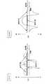
さらに、例えば、周辺セルにおいて同一の周波数を使用するリユース1(周波数繰り返し1)のシステムでは、図20に示すように、NodeB#1が自セル内のUEに送信した信号は、周辺セル(NodeB#2及び#3)にとっては干渉となる。このようなシステムでは、自セルで使用するサブキャリア数で周辺セルに与える干渉が決まり、周辺セルに与える干渉が多いと、システム全体のスループットの低下を招いてしまう。このため、限られたサブキャリア数で効率良く伝送することが必要となる。 Further, for example, in the reuse 1 (frequency repetition 1) system using the same frequency in the neighboring cell, as shown in FIG. 20, the signal transmitted by
本発明の目的は、自セル及び周辺セルのスループットを向上させる端末装置、無線通信方法、基地局装置及び送受信方法を提供することである。An object of the present invention is to provide aterminal device, a wireless communication method, a base station device, and a transmission / reception method that improve the throughput of the own cell and neighboring cells.
本発明の端末装置は、各サブキャリアブロックの回線状態を測定する回線状態測定手段と、基地局から送信された選択基準情報に基づいて、測定された前記回線状態が上位の複数のサブキャリアブロックを選択するサブキャリアブロック選択手段と、選択された前記複数のサブキャリアブロックの回線状態の全てを反映した一つのCQIを生成するCQI生成手段と、生成された前記一つのCQIと選択された前記複数のサブキャリアブロックを示す情報とを前記基地局に報告する報告手段と、具備する構成を採る。
Theterminal device according to the present invention includes a plurality of subcarrier blocks whose channel states are measured based on channel state measuring means for measuring the channel state of each subcarrier blockand the selection criterion information transmitted from thebase station. Subcarrier block selecting means for selecting the CQI generating means for generating one CQI reflecting all of the channel states of the selected subcarrier blocks, and the one selected for the generated CQI A reporting means for reporting information indicating a plurality of subcarrier blocks to thebase station is employed.
本発明によれば、自セル及び周辺セルのスループットを向上させることができ、したがって、システム全体のスループットを向上させることができる。 According to the present invention, the throughput of the own cell and the peripheral cells can be improved, and therefore the throughput of the entire system can be improved.
本発明の骨子は、自セル及び周辺セルのトラヒック量によって決められた判定基準に基づいて、受信品質が上位のサブキャリアを使用するサブキャリアとして選択し、選択したサブキャリアの平均受信品質を示す報告値を生成し、生成した報告値と使用するサブキャリアを示す情報とを通信相手に報告することである。 The essence of the present invention is that the reception quality is selected as a subcarrier using a higher-order subcarrier based on a criterion determined by the traffic volume of the own cell and neighboring cells, and shows the average reception quality of the selected subcarrier. A report value is generated, and the generated report value and information indicating a subcarrier to be used are reported to a communication partner.
本発明の実施の形態では、特に断らない限り、図1に示すように、使用するサブキャリア数を512とし、32サブキャリアを1サブキャリアブロック(以下、単に「ブロック」という)として計16ブロックを用い、ブロック単位で割り当てを行うものとする。このブロックには、ブロックを識別するための番号(ブロック番号)が付けられている。 In the embodiment of the present invention, unless otherwise specified, as shown in FIG. 1, the number of subcarriers to be used is 512, and 32 subcarriers are one subcarrier block (hereinafter simply referred to as “block”), for a total of 16 blocks. It is assumed that allocation is performed in block units. This block is given a number (block number) for identifying the block.
(実施の形態1)
図2は、本発明の実施の形態1に係る基地局装置の送信系の構成を示すブロック図である。この図において、スケジューラ部201は、通信中の各通信端末装置から報告されたCQIに基づいて、次のフレームでどの通信端末装置に送信するかの決定(スケジューリング)を行い、決定したスケジューリング情報をユーザ選択部202に出力する。このスケジューリングのアルゴリズムとしては、Max C/I, Proportional Fairnessなどがある。また、スケジューリングにおいて、送信するユーザ信号を決定したら、そのユーザ信号に対して変調方式や符合化率(MCS:Modulation and Coding Scheme)を割り当て、割り当てたMCSを符号化部203−1、203−2及び変調部204−1、204−2に通知する。さらに、同時に、各通信端末装置から使用可能なブロック番号の報告を受け、報告されたブロックのうち、どのブロックを使用するか通信端末装置毎に決定し、サブキャリアマッピング部205−1、205−2に通知する。(Embodiment 1)
FIG. 2 is a block diagram showing a configuration of a transmission system of the base station apparatus according to
ユーザ選択部202は、各通信端末装置(この図では、一例としてUE1〜UE3とする)に送信する送信データを一時記憶し、スケジューラ部201から出力されたスケジューリング情報に従って、送信先となる通信端末装置に送信するデータを選択し、符号化部203−1、203−2に出力する。 The
本実施の形態では、符号化、変調、サブキャリアマッピングを行う系列を2系列備え、ユーザ選択部202で2つ送信データを選択し、それぞれの系列において同じ内容の処理を並列に行うことができる。このため、一系列についてのみ説明する。さらに、制御用データについて、符号化、変調、サブキャリアマッピングを行う制御用データ処理部207としてもう一系列用意されている。制御用データ処理部207については後述する。 In this embodiment, two sequences for encoding, modulation, and subcarrier mapping are provided, and two transmission data can be selected by
符号化部203−1は、ユーザ選択部202から出力された送信データに、スケジューラ部201から通知された符号化率でターボ符号などを用いて符号化処理を行い、変調部204−1に出力する。変調部204−1は、符号化部203−1から出力された送信データに、スケジューラ部201から通知された変調方式で変調処理を行い、サブキャリアマッピング部205−1に出力する。サブキャリアマッピング部205−1は、変調部204−1から出力された変調後の送信データを、スケジューラ部201で決定されたサブキャリアにマッピングし、多重部208に出力する。 The encoding unit 203-1 performs encoding processing on the transmission data output from the
閾値算出部206は、自セル及び周辺セルのトラヒック情報に基づいて、通信端末装置において使用可能なブロックを選択するための選択基準であるCIR閾値を算出する。CIR閾値(ThCIR)の算出は、例えば、ThCIR=S0−10log(γ0/Σγi)とする。このとき、S0は基準CIRで例えば、−10dBである。γ0は自セルのトラヒック量であり、10log(γ0/Σγi)は自セルのトラヒック量と自セル及び周辺6セルの合計トラヒック量の比(dB)となる。S0=−10dB、γ0/Σγi=1/10であるときには、設定するCIR閾値は0dBとなる。このように算出された閾値情報は、制御用データ処理部207に出力される。The
制御用データ処理部207では、閾値算出部206から出力された閾値情報を符号化処理(符号化部207−1)、変調処理(変調部207−2)、及び、サブキャリアへのマッピング処理(サブキャリアマッピング部207−3)が行われ、多重部208に出力される。 In the control data processing unit 207, the threshold information output from the
多重部208は、サブキャリアマッピング部205−1、205−2、207−3から出力された送信データ及び閾値情報を含む制御用データ、さらにパイロット系列を多重し、S/P変換部209に出力する。S/P変換部209は、多重部208から出力された多重信号を複数系列の送信データに変換し、IFFT部210に出力する。IFFT部210は、S/P変換部209から出力された複数系列の送信データに逆高速フーリエ変換を行うことにより、OFDM信号を形成し、GI挿入部211に出力する。GI挿入部211は、IFFT部210から出力されたOFDM信号にガードインターバル(GI)を挿入し、無線処理部212に出力する。無線処理部212は、GI挿入部211から出力された信号にD/A変換やアップコンバートなどの所定の無線処理を行い、無線処理後の信号をアンテナを介して通信端末装置に送信する。 Multiplexing
図3は、本発明の実施の形態1に係る通信端末装置の受信系の構成を示すブロック図である。この図において、無線処理部301は、基地局装置から送信された信号をアンテナを介して受信し、受信した信号にダウンコンバートやA/D変換などの所定の無線処理を行い、無線処理後の信号をGI除去部302に出力する。GI除去部302は、無線処理部301から出力された信号からガードインターバルを除去し、除去した信号をFFT部303に出力する。FFT部303は、GI除去部302から出力された信号に対して高速フーリエ変換を行うことにより、それぞれのブロックにより伝送された信号を取得する。取得したブロック毎の信号は、チャネル分離部304に出力される。 FIG. 3 is a block diagram showing a configuration of a reception system of the communication terminal apparatus according to
チャネル分離部304は、FFT部303から出力されたブロック毎(実際にはサブキャリア毎)の信号をユーザ毎の系列に分離し、自装置に宛てられたデータ部、パイロット部及び制御用データ部(閾値情報を含む)を取り出す。取り出されたデータ部は、復調部305−1に出力され、復調部305−1において復調処理が施され、復号部306−1に出力される。復号部306−1は、復調部305−1から出力された復調信号を復号し、ユーザデータを取り出す。一方、チャネル分離部304で取り出された制御用データ部は、復調部305−2に出力され、復調部305−2において復調処理が施され、復号部306−2に出力される。復号部306−2は、復調部305−2から出力された復調信号を復号し、制御用データを取り出し、制御用データに含まれた閾値情報をブロック選択部308に出力する。さらに、チャネル分離部304で取り出されたパイロット部は、受信品質測定手段としてのCIR測定部307に出力され、全サブキャリアについてCIRが測定される。CIRの測定結果は、ブロック選択部308に出力される。 The
ブロック選択部308は、CIR測定部307から出力されたCIR測定結果について、復号部306−2から出力された閾値情報に基づいて閾値判定を行う。すなわち、閾値以上のブロックを使用可能なブロックとして選択し、選択されたブロックのCIRをCIR平均化部309に出力する。また、選択されたブロックの番号は、図示せぬ送信部に出力される。 The
CIR平均化部309は、ブロック選択部308から出力された使用可能ブロックのCIRを平均化し、平均化した値をCQI生成部310に出力する。 The
CQI生成部310は、CIR、変調方式(QPSKや16QAMなど)、符号化率等がCQIと対応付けられたCQIテーブルを備えており、CIR平均化部309で平均化された値に基づいてCQIテーブルからCQIを検索し、CQIを生成する。生成したCQIは図示せぬ送信部に出力される。すなわち、閾値以上となるブロックのCIRを平均化した値に相当するCQIを生成するものである。 The
CQI生成部310から出力されたCQIと使用可能ブロック番号は、上り回線で基地局装置に送信される。 The CQI and usable block number output from
上述した基地局装置及び通信端末装置の動作について、自セル及び周辺セルのトラヒック量が多きときと少ないときに分けて図4から図7を用いて説明する。まず、トラヒック量が多いときについて、図4及び図5を用いて説明する。 The operations of the base station apparatus and communication terminal apparatus described above will be described with reference to FIGS. 4 to 7 separately when the traffic volume of the own cell and neighboring cells is large and small. First, the case where the traffic amount is large will be described with reference to FIGS.
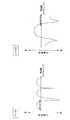
通信端末装置におけるブロック選択部308では、図4に示すようなブロックの選択が行われる。図4は、本発明の実施の形態1における使用可能なブロックの選択方法を説明するための図である。ここでは、CIRの様子を2通り挙げ、同レベルのCIRとなる山が複数あるケース1、高CIRとなる山が一つしかないケース2として示した。通信端末装置のブロック選択部308では、ブロック毎に測定されたCIRと基地局装置から送信された閾値情報とに基づいて、閾値判定が行われる。この閾値は、自セル及び周辺セルのトラヒックが多いことを反映しており、比較的高めに設定されている。このため、閾値以上となるブロックは少なめになり、周辺セルに与える干渉を少なくすることができる。 The
ブロック選択部308での閾値判定は、図4に示すように、閾値以上となるCIRが測定されたブロックは使用可能なブロックとして選択され、閾値未満となるCIRが測定されたブロックは使用不可能なブロックとして除外される。そして、使用可能として選択されたブロックのCIRがCIR平均化部309に出力され、選択されたブロックの番号(情報)が送信部に出力される。 As shown in FIG. 4, the
CIR平均化部309では、ブロック選択部308から出力されたCIRを1ブロック当たりのCIRに平均化し、CQI生成部310では、平均化されたCIRに相当するCQIを生成する。生成されたCQIは送信部に出力され、ブロック選択部308から出力されたブロック番号と共に、基地局装置に送信される。これにより、閾値以上となる全てのブロックについてCQIを基地局装置に報告する必要がなくなり、上り回線の伝送データ量を削減することができる。 The
基地局装置では、各通信端末装置から報告されたCQIと使用可能ブロック番号とに基づいて、スケジューラ部201がブロックの割り当てを行う。図5は、本発明の実施の形態1におけるブロックの割り当て例を示す図である。なお、ここでは、ブロックの割り当て対象となる通信端末装置数を2とし、UE1、UE2として表記する。基地局装置は、図5に示すように、UE1にブロック番号14及び15を割り当て、UE2にブロック番号8〜11を割り当てており、それぞれのUEにおける受信品質が良好なブロックのみの比較的少ない割り当てとなっている。 In the base station apparatus, the
このように、自セル及び周辺セルのトラヒック量が多い場合に、閾値を低くして、自セルで多くのブロックを割り当ててしまうと、周辺セルに多くの干渉を与えてしまい、周辺セルではブロックをほとんど使用できなくなるので、システム全体のスループットが低下してしまう。このため、閾値を高くすることにより、自セルで使用するブロックを少なくすることで、周辺セルに与える干渉を低減することができる。これにより、周辺セルのスループットの向上を図ることができる。一方、閾値を高くしすぎると、自セルでの使用可能ブロックが極端に少なくなり、自セルでのスループットの低下を招いてしまうため、周辺セルに多くの干渉を与えない範囲で、自セルで使用するブロック数を多くする必要がある。 In this way, when the traffic volume of the own cell and the neighboring cell is large, if the threshold is lowered and many blocks are allocated in the own cell, a lot of interference is given to the neighboring cell, and the neighboring cell is blocked. Since the system cannot be used, the throughput of the entire system is reduced. For this reason, the interference given to a surrounding cell can be reduced by making the threshold value high and reducing the block used by the own cell. Thereby, the throughput of the peripheral cell can be improved. On the other hand, if the threshold is set too high, the number of usable blocks in the own cell will be extremely small, leading to a decrease in throughput in the own cell. It is necessary to increase the number of blocks used.
次に、自セル及び周辺セルのトラヒック量が少ないときについて、図6及び図7を用いて説明する。 Next, the case where the traffic volume of the own cell and the surrounding cells is small will be described with reference to FIGS.
図6は、本発明の実施の形態1における使用可能なブロックの選択方法を説明するための図である。この図では、閾値以外は図4と同じ条件である。トラヒック量の少ない場合の閾値は、トラヒック量の多い場合に比べ小さく設定される。このため、閾値以上となるブロックは多めになり、より多くのブロックを使用することができるが、トラヒックが少ないときには周辺セルでの時間的なチャネル使用率が低いため、周辺セルに与える干渉はそれほど問題にならない。 FIG. 6 is a diagram for explaining a method of selecting usable blocks in the first embodiment of the present invention. In this figure, conditions other than the threshold are the same as in FIG. The threshold when the traffic volume is small is set smaller than when the traffic volume is large. For this reason, there are more blocks that exceed the threshold, and more blocks can be used.However, when the traffic is low, the temporal channel usage rate in the neighboring cells is low, so the interference given to the neighboring cells is less. It doesn't matter.
トラヒック量が少ない場合も、トラヒック量が多い場合と同様に、閾値以上となるブロックを使用可能ブロックとし、使用可能ブロックのCIRを平均化した値に基づいてCQIを生成し、CQIと使用可能なブロック番号とが送信部から基地局装置に送信される。 Even when the traffic volume is small, as in the case where the traffic volume is large, a block that is equal to or greater than the threshold is set as a usable block, and a CQI is generated based on an average value of the CIRs of the usable blocks, and can be used with the CQI. The block number is transmitted from the transmission unit to the base station apparatus.
基地局装置でも、トラヒック量が多い場合と同様に、各通信端末装置から報告されたCQIと使用可能ブロック番号とに基づいて、スケジューラ部201がブロックの割り当てを行う。図7は、本発明の実施の形態1におけるブロックの割り当て例を示す図である。基地局装置は、図7に示すように、UE1にブロック番号3〜5、及び13〜16を割り当て、UE2にブロック番号6〜12を割り当てており、トラヒック量が多い場合に比べ、多くのブロックを割り当てている。 Also in the base station apparatus, similarly to the case where the traffic volume is large, the
このように、トラヒック量の多い場合も、少ない場合も、受信品質が高いブロックのみを使用するため、高いMCSを割り当てることができる。例えば、品質の悪いブロックも含めた12のブロックを使ってQPSKで送信するのと、品質の良いブロックのみ6ブロックを使って64QAMで送信するのとでは後者の方が1.5倍のスループットが得られる上、他セルに与える干渉も半分ですむことになる。 As described above, a high MCS can be allocated because only a block with high reception quality is used regardless of whether the traffic volume is large or small. For example, 12 blocks including poor quality blocks are transmitted by QPSK, and only 6 blocks having good quality are transmitted by 64 QAM using 6 blocks. The latter has 1.5 times the throughput. In addition to being obtained, interference with other cells can be halved.
なお、トラヒック量の多少にかかわらず、複数の通信端末装置が同時に同一のブロックを使用可能としたときは、CQIが高い方の通信端末装置に割り当てるようにしてもよい。 Note that when a plurality of communication terminal devices can use the same block at the same time regardless of the amount of traffic, it may be assigned to a communication terminal device with a higher CQI.
また、ブロック選択部308で行う閾値判定には、各ブロックのCIRから全ブロックの平均CIRを差し引いた差分、すなわち(各ブロックのCIR−平均CIR)とすることも考えられる。こうすることにより、セル中心部のユーザも相対的に品質の高いブロックのみを使用し、効率的に周辺セルに与える干渉を抑えることが可能である。 The threshold determination performed by the
このように本実施の形態によれば、所定の閾値を超える受信品質が高いブロックのみを使用するブロックとして選択できるため、高いMCSで伝送することにより、限られたブロックの中で周辺セルに与える干渉を抑えながらスループットを向上させることができる。また、自セル及び周辺セルのトラヒック量に応じて、使用可能ブロックの選択に用いる閾値を変動させることは、許容できる他セル与干渉量を反映するため、高効率な伝送を行うことができる。 As described above, according to the present embodiment, since only a block having a high reception quality exceeding a predetermined threshold can be selected as a block to be used, transmission is performed with a high MCS to give to neighboring cells in a limited block. Throughput can be improved while suppressing interference. Also, changing the threshold value used for selection of usable blocks according to the traffic volume of the own cell and neighboring cells reflects an allowable amount of interference with other cells, and therefore, highly efficient transmission can be performed.
(実施の形態2)
実施の形態1では、CIRの閾値判定により使用可能なブロックの選択を行い、その閾値は自セル及び周辺セルのトラヒック量に応じて制御される場合について説明したが、本発明の実施の形態2では、所定のブロック数内で使用可能なブロックの選択を行い、そのブロック数はトラヒック量に応じて決定される場合について説明する。(Embodiment 2)
In the first embodiment, a case has been described in which usable blocks are selected by CIR threshold determination, and the threshold is controlled according to the traffic volume of the own cell and neighboring cells, but the second embodiment of the present invention. Now, a case will be described in which usable blocks are selected within a predetermined number of blocks, and the number of blocks is determined according to the traffic volume.
図8は、本発明の実施の形態2に係る基地局装置の送信系の構成を示すブロック図である。ただし、図8が図2と共通する部分には、図2と同一の符号を付し、その詳しい説明は省略する。図8が図2と異なる点は、閾値算出部206を割り当てブロック数算出部801に変更した点である。 FIG. 8 is a block diagram showing a configuration of a transmission system of the base station apparatus according to
割り当てブロック数算出部801は、自セル及び周辺セルのトラヒック量に基づいて、通信端末装置において使用可能なブロックを選択するための選択基準であるブロック数を算出する。ブロック数(Nsbとする)の算出は、例えば、以下のような式で表すことができる。
割り当てブロック数算出部801において、選択可能なブロック数を少なくすると、周辺セルに与える干渉を小さくすることができる。周辺セルに多くの干渉を与えてしまうと、ブロックをほとんど使用できなくなり、システムスループットを低下させてしまう。一方、選択可能なブロック数を少なくしすぎると、自セル内でのスループットの低下を招いてしまう。そのため、本実施の形態では、自セル及び周辺セルのトラヒック量を考慮して、選択可能なブロック数を決めることにより、周辺セルに多くの干渉を与えることと、自セルのスループットが低下することを回避することができる。 If the number of blocks that can be selected is reduced in the allocation block
本発明の実施の形態2に係る通信端末装置の受信系の構成は、図3と同一であり、ブロック選択部308の機能が異なるのみなので、図3を代用して説明し、図3と共通する機能ブロックについては、その詳しい説明は省略する。復号部306−2は、復調部305−2から出力された制御用データ部に対して復号処理を行い、制御用データを取り出し、制御用データに含まれた選択可能ブロック数情報をブロック選択部308に通知する。 The configuration of the reception system of the communication terminal apparatus according to
ブロック選択部308は、CIR測定部307において全ブロックについて測定されたCIRと、復号部306−2から出力された選択可能ブロック数(Nsb)とに基づいて、使用可能ブロックを選択する。具体的には、CIRの上位Nsbブロックを選択し、使用可能ブロックとする。選択された使用可能ブロックのCIRは、CIR平均化部309において平均化され、CQI生成部310においてCIR平均値に相当するCQIが生成されて、CQIが送信部に出力される。また、ブロック選択部308において選択された使用可能ブロックのブロック番号は、送信部に出力される。The
上述した基地局装置及び通信端末装置の動作について図9及び図10を用いて説明する。通信端末装置におけるブロック選択部308では、図9に示すようなブロックの選択が行われる。図9は、本発明の実施の形態2における使用可能なブロックの選択方法を説明するための図である。ここでは、使用可能ブロック数(Nsb)を6とし、CIRの様子を2通り挙げ、同レベルのCIRとなる山が複数あるケース1、高CIRとなる山が一つしかないケース2として示した。ブロック選択部308では、ブロック毎に測定されたCIRと基地局装置から送信された使用可能ブロック数情報とに基づいて、使用可能ブロックの選択が行われる。すなわち、各ブロックのCIR上位Nsb分を使用可能ブロックとして選択するものであり、図9のケース1、ケース2に示す通り、いずれも指定された使用可能ブロック数が6ブロック選択される。Operations of the base station apparatus and communication terminal apparatus described above will be described with reference to FIGS. The
ここで、選択されるブロックをCIRの上位からとしたのは、品質の悪いブロックを割り当てることを防ぐことができ、高効率な伝送が可能となり、周辺セルに与える干渉を軽減することができるためである。これにより、システム全体のスループットを向上させることができる。 Here, the reason why the selected block is selected from the top of the CIR is that it is possible to prevent allocation of a block having poor quality, to enable highly efficient transmission, and to reduce interference given to neighboring cells. It is. Thereby, the throughput of the entire system can be improved.
また、本実施の形態のように、MCSを割り当てる場合には、品質の高いブロックを使用すれば、より高いMCSを割り当てることができるので、さらに、スループットを向上させることができる。例えば、品質の悪いブロックも含めた12のブロックを使ってQPSKで送信するのと、品質の良いブロックのみ6ブロックを使って64QAMで送信するのでは後者の方が1.5倍のスループットが得られる上、他セルに与える干渉も半分ですむことになる。 Further, when MCS is allocated as in the present embodiment, if a high quality block is used, a higher MCS can be allocated, so that the throughput can be further improved. For example, if 12 blocks including poor quality blocks are used for transmission with QPSK, and only 6 blocks with good quality are used for transmission with 64 QAM, the latter yields 1.5 times the throughput. In addition, the interference with other cells can be halved.
選択された使用可能ブロックのCIRは、CIR平均化部309において平均化され、CQI生成部310においてCIR平均値に相当するCQIが生成されて、CQIが送信部に出力される。また、ブロック選択部308において選択された使用可能ブロックのブロック番号は、送信部に出力される。 The CIRs of the selected usable blocks are averaged by the
基地局装置では、各通信端末装置から報告されたCQIと使用可能ブロック番号とに基づいて、スケジューラ部201がブロックの割り当てを行う。図10は、本発明の実施の形態2におけるブロックの割り当て例を示す図である。なお、ここでは、図9のケース1に示した使用可能ブロックをUE1に割り当てる場合を例示している。基地局装置はUE1にブロック番号4,5,9,10,14,15を割り当てている。 In the base station apparatus, the
このように本実施の形態によれば、受信品質が高いブロックを所定ブロック数選択し、使用するブロックとするため、高いMCSで伝送することにより、限られた使用可能ブロックの中で周辺セルに与える干渉を抑えながらスループットを向上させることができる。また、自セル及び周辺セルのトラヒック量に応じて、使用可能なブロック数を変動させることは、許容できる他セル与干渉量を反映するため、高効率な伝送を行うことができる。 As described above, according to the present embodiment, a predetermined number of blocks having high reception quality are selected and used as blocks to be used. Therefore, by transmitting with a high MCS, it can be transmitted to neighboring cells in a limited usable block. Throughput can be improved while suppressing interference. In addition, changing the number of usable blocks according to the traffic volume of the own cell and the neighboring cells reflects an allowable interference amount with other cells, so that highly efficient transmission can be performed.
(実施の形態3)
本発明の実施の形態3では、自セル及び周辺セルのトラヒック量に応じて通信端末装置が使用できるブロックを予め決定し、さらに実施の形態1で説明したCIR閾値により、使用するブロックの選択を行う場合について説明する。(Embodiment 3)
In the third embodiment of the present invention, blocks that can be used by the communication terminal apparatus are determined in advance according to the traffic volume of the own cell and neighboring cells, and the block to be used is selected based on the CIR threshold described in the first embodiment. The case where it performs is demonstrated.
図11は、本発明の実施の形態3に係る基地局装置の送信系の構成を示すブロック図である。ただし、図11が図2と共通する部分は、図2と同一の符号を付し、その詳しい説明は省略する。図11が図2と異なる点は、指定ブロック決定部1101を追加した点と、スケジューラ部201をスケジューラ部1102に変更した点である。 FIG. 11 is a block diagram showing a configuration of a transmission system of the base station apparatus according to
閾値算出部206は、自セル及び周辺セルのトラヒック情報に基づいて、通信端末装置において使用可能なブロックを判定するためのCIR閾値を算出する。算出した閾値は、制御用データ処理部207に出力される。 The
指定ブロック決定部1101は、自セル及び周辺セルのトラヒック量に基づいて、通信端末装置に指定するブロック(選択可能なブロック)を決定する。決定した指定ブロック情報(選択基準情報)は、スケジューラ部1102と制御用データ処理部207とに出力される。 The designated
スケジューラ部1102は、通信中の各通信端末装置から報告されたCQI、使用可能なブロック番号、及び、指定ブロック決定部1101から出力された指定ブロック情報に基づいて、次のフレームでどの通信端末装置に送信するかの決定を行い、決定したスケジューリング情報をユーザ選択部202に出力する。その他の処理については、実施の形態1と同様である。 The
図12は、本発明の実施の形態3に係る通信端末装置の受信系の構成を示すブロック図である。ただし、図12が図3と共通する部分は、図3と同一の符号を付し、その詳しい説明は省略する。図12が図3と異なる点は、CIR測定部307をCIR測定部1201に変更した点である。 FIG. 12 is a block diagram showing a configuration of a reception system of the communication terminal apparatus according to
復号部306−2は、復調部305−2から出力された制御用データ部に対して復号処理を行い、制御用データを取り出し、制御用データに含まれた指定ブロック情報をCIR測定部1201に出力し、同じく制御用データに含まれた閾値情報をブロック選択部308に出力する。 Decoding section 306-2 performs a decoding process on the control data section output from demodulation section 305-2, extracts the control data, and sends the designated block information included in the control data to
CIR測定部1201は、チャネル分離部304から出力されたパイロット部のうち、復号部306−2から出力された指定ブロック情報が示すブロックのパイロット部についてのみCIRの測定を行う。ここでは、基地局装置から指定されたブロックについてのみCIRの測定を行うので、全ブロックについてCIRを測定する場合に比べ、CIR測定に要する処理量を削減すると共に、処理に要する時間を短縮することができる。測定されたCIRはブロック選択部308に出力される。
ブロック選択部308は、CIR測定部1201から出力されたCIR測定結果について、復号部306−2から出力された閾値情報に基づいて閾値判定を行う。ブロック選択部308においても、CIR測定部1201から出力されるCIRの測定結果が全ブロックについてではなく、基地局装置により指定されたブロックについてのみ閾値判定を行えばよいので、処理量の削減と共に、処理に要する時間を短縮することができる。閾値判定の結果、閾値以上となるブロックを使用可能ブロックとし、このブロックのCIRをCIR平均化部309に出力し、このブロックの番号を図示せぬ送信部に出力する。 The
上述した基地局装置及び通信端末装置の動作について、図13を用いて説明する。図13は、本発明の実施の形態3における使用可能なブロックの選択方法を説明するための図である。ここでは、CIRの様子を2通り挙げ、同レベルのCIRとなる山が複数あるケース1、高CIRとなる山が一つしかないケース2として示した。通信端末装置のブロック選択部308では、基地局装置で指定されたブロックについて測定されたCIRが、基地局装置から送信された閾値情報に基づいて閾値判定が行われる。図13のケース1において、基地局装置から指定されたブロックは、左から5ブロックであるが、閾値を越えるブロックは、左から4ブロックまでである。また、図13のケース2において、基地局装置から指定されたブロックはケース1と同様、左から5ブロックであるが、閾値を越えるブロックは、左から5ブロック目のみである。これにより、通信端末装置で選択される使用可能ブロックは予め指定されたブロックの中に限定されるため、基地局装置に使用可能ブロックの番号を報告する際、ブロック番号のデータ量を削減することができる。 Operations of the above-described base station apparatus and communication terminal apparatus will be described with reference to FIG. FIG. 13 is a diagram for explaining a method of selecting usable blocks in the third embodiment of the present invention. Here, two modes of CIR are listed, and a
このように本実施の形態によれば、自セル及び周辺セルのトラヒック量に応じて、基地局装置が通信端末装置に割り当てるブロックを予め指定することにより、通信端末装置における使用可能ブロックの選択に要する処理量及び処理時間を削減することができると共に、基地局装置に報告する使用ブロック番号の情報量を削減することができる。 As described above, according to the present embodiment, the base station apparatus specifies in advance the blocks to be allocated to the communication terminal apparatus according to the traffic volume of the own cell and the neighboring cells, thereby enabling selection of usable blocks in the communication terminal apparatus. The required processing amount and processing time can be reduced, and the information amount of the used block number reported to the base station apparatus can be reduced.
なお、基地局装置で指定するブロックは、毎回計算して通知するのではなく、予め決められたパタンに従って変更することも考えられる。 Note that the block specified by the base station apparatus may be changed according to a predetermined pattern instead of being calculated and notified each time.
また、本実施の形態は、通信端末装置に割り当てるブロックを制限したうえで、実施の形態1に適用した場合について説明したが、同様に実施の形態2に適用することも考えられる。実施の形態2に適用した場合、指定されたブロックの中から、CIRの上位Nsbブロックについて使用可能ブロックとして選択されることになる。Moreover, although this Embodiment limited the block allocated to a communication terminal device, and demonstrated the case where it applied to
なお、上述した各実施の形態では、MCSを割り当てる場合について説明したが、本発明はMCSを割り当てない場合でも適用することができる。 In each of the above-described embodiments, the case where the MCS is allocated has been described. However, the present invention can be applied even when the MCS is not allocated.
また、各実施の形態では、閾値の算出、割り当てブロック数の算出、指定ブロックの決定を基地局装置で行ったが、上位制御装置で行ってもよい。これらの算出及び決定は、トラヒック情報に基づいて行ったが、ユーザ数に基づいて行ってもよい。 In each embodiment, the calculation of the threshold value, the calculation of the number of allocated blocks, and the determination of the designated block are performed by the base station device, but may be performed by the host control device. These calculations and determinations are performed based on traffic information, but may be performed based on the number of users.
また、各実施の形態では、使用するサブキャリア数を512とし、1ブロックを32サブキャリアとしたが、本発明はこれにかぎらず、任意に設定してもよい。 In each embodiment, the number of subcarriers used is 512 and one block is 32 subcarriers. However, the present invention is not limited to this, and may be arbitrarily set.
201、1102 スケジューラ部
202 ユーザ選択部
203−1、203−2、207−1 符号化部
204−1、204−2、207−2 変調部
205−1、205−2、207−3 サブキャリアマッピング部
206 閾値算出部
207 制御用データ処理部
208 多重部
209 S/P変換部
210 IFFT部
211 GI挿入部
212、301 無線処理部
302 GI除去部
303 FFT部
304 チャネル分離部
305−1、305−2 復調部
306−1、306−2 復号部
307、1201 CIR測定部
308 ブロック選択部
309 CIR平均化部
310 CQI生成部
801 割り当てブロック数算出部
1101 指定ブロック決定部
201, 1102
Claims (4)
Translated fromJapanese基地局から送信された選択基準情報に基づいて、測定された前記回線状態が上位の複数のサブキャリアブロックを選択するサブキャリアブロック選択手段と、
選択された前記複数のサブキャリアブロックの回線状態の全てを反映した一つのCQIを生成するCQI生成手段と、
生成された前記一つのCQIと選択された前記複数のサブキャリアブロックを示す情報とを前記基地局に報告する報告手段と、
を具備する端末装置。A line state measuring means for measuring the line state of each subcarrier block;
Subcarrier block selection means for selecting a plurality of subcarrier blocks whose measured channel state is higherbased on selection criterion information transmitted from a base station ;
CQI generating means for generating one CQI reflecting all the channel states of the selected plurality of subcarrier blocks;
Reporting means for reporting the generated one CQI and information indicating the selected subcarrier blocks to thebase station ;
Aterminal device comprising:
選択された前記複数のサブキャリアブロックの回線状態の全てを反映した一つのCQIを生成し、
生成された前記一つのCQIと選択された前記複数のサブキャリアブロックを示す情報とを前記基地局に報告する
無線通信方法。Based on the selection criteria information transmitted from the base station, select a plurality of subcarrier blocks with higher line conditions,
Generating one CQI reflecting all the channel states of the selected subcarrier blocks;
A radio communication method for reporting the generated CQI and information indicating the selected subcarrier blocks to thebase station .
端末装置にサブキャリアブロックの選択基準情報を含む信号を送信する送信手段と、Transmitting means for transmitting a signal including selection criterion information of a subcarrier block to a terminal device;
前記選択基準情報が示す選択基準を満たす複数のサブキャリアブロックの回線状態の全てを反映した一つのCQIを含む信号を、前記端末装置から受信する受信手段と、Receiving means for receiving, from the terminal device, a signal including one CQI reflecting all the channel states of a plurality of subcarrier blocks that satisfy the selection criteria indicated by the selection criteria information;
を具備し、Comprising
前記複数のサブキャリアブロックは前記端末装置によって選択された回線品質が上位のサブキャリアブロックである基地局装置。The base station apparatus, wherein the plurality of subcarrier blocks are subcarrier blocks having higher channel quality selected by the terminal apparatus.
端末装置にサブキャリアブロックの選択基準情報を含む信号を送信し、Transmit a signal including selection criteria information of the subcarrier block to the terminal device,
前記選択基準情報が示す選択基準を満たす複数のサブキャリアブロックの回線状態の全てを反映した一つのCQIを含む信号を、前記端末装置から受信し、Receiving a signal including one CQI reflecting all the channel states of a plurality of subcarrier blocks satisfying the selection criterion indicated by the selection criterion information from the terminal device;
前記複数のサブキャリアブロックは前記端末装置によって選択された回線品質が上位のサブキャリアブロックである送受信方法。The transmission / reception method in which the plurality of subcarrier blocks are subcarrier blocks having higher channel quality selected by the terminal device.
Priority Applications (1)
| Application Number | Priority Date | Filing Date | Title |
|---|---|---|---|
| JP2011123416AJP5306416B2 (en) | 2011-06-01 | 2011-06-01 | Terminal apparatus, wireless communication method, base station apparatus, and transmission / reception method |
Applications Claiming Priority (1)
| Application Number | Priority Date | Filing Date | Title |
|---|---|---|---|
| JP2011123416AJP5306416B2 (en) | 2011-06-01 | 2011-06-01 | Terminal apparatus, wireless communication method, base station apparatus, and transmission / reception method |
Related Parent Applications (1)
| Application Number | Title | Priority Date | Filing Date |
|---|---|---|---|
| JP2010237813ADivisionJP4785982B2 (en) | 2010-10-22 | 2010-10-22 | Wireless communication apparatus, wireless communication method, and wireless communication system |
Publications (2)
| Publication Number | Publication Date |
|---|---|
| JP2011193529A JP2011193529A (en) | 2011-09-29 |
| JP5306416B2true JP5306416B2 (en) | 2013-10-02 |
Family
ID=44797878
Family Applications (1)
| Application Number | Title | Priority Date | Filing Date |
|---|---|---|---|
| JP2011123416AExpired - LifetimeJP5306416B2 (en) | 2011-06-01 | 2011-06-01 | Terminal apparatus, wireless communication method, base station apparatus, and transmission / reception method |
Country Status (1)
| Country | Link |
|---|---|
| JP (1) | JP5306416B2 (en) |
Families Citing this family (1)
| Publication number | Priority date | Publication date | Assignee | Title |
|---|---|---|---|---|
| US10986649B2 (en) | 2016-10-31 | 2021-04-20 | Nec Corporation | Communication apparatus, communication system, communication method, and non-transitory computer readable medium |
Family Cites Families (2)
| Publication number | Priority date | Publication date | Assignee | Title |
|---|---|---|---|---|
| US6947748B2 (en)* | 2000-12-15 | 2005-09-20 | Adaptix, Inc. | OFDMA with adaptive subcarrier-cluster configuration and selective loading |
| JP4785982B2 (en)* | 2010-10-22 | 2011-10-05 | パナソニック株式会社 | Wireless communication apparatus, wireless communication method, and wireless communication system |
- 2011
- 2011-06-01JPJP2011123416Apatent/JP5306416B2/ennot_activeExpired - Lifetime
Also Published As
| Publication number | Publication date |
|---|---|
| JP2011193529A (en) | 2011-09-29 |
Similar Documents
| Publication | Publication Date | Title |
|---|---|---|
| JP4256158B2 (en) | Wireless communication apparatus and wireless communication method | |
| US9985743B2 (en) | Channel quality indicator for time, frequency and spatial channel in terrestrial radio access network | |
| US8768391B2 (en) | Localised and distributed scheduling control method and apparatus | |
| US8284731B2 (en) | Communication terminal apparatus, communication control apparatus, wireless communication system, and communication method all using a plurality of slots | |
| CN101331693A (en) | Wireless communication method, wireless communication system, base station, and mobile station | |
| JP4734314B2 (en) | Wireless communication apparatus and wireless communication method | |
| JP4785982B2 (en) | Wireless communication apparatus, wireless communication method, and wireless communication system | |
| JP4734389B2 (en) | Wireless communication apparatus and wireless communication method | |
| JP5306416B2 (en) | Terminal apparatus, wireless communication method, base station apparatus, and transmission / reception method | |
| KR100877746B1 (en) | Map Construction Method and Frame Transmission Device Using the PFDMA Based Wireless Communication System | |
| HK40018199A (en) | Radio communication apparatus and radio communication method | |
| HK40018199B (en) | Radio communication apparatus and radio communication method | |
| HK1237137A1 (en) | Radio communication apparatus and radio communication method | |
| HK1237137B (en) | Radio communication apparatus and radio communication method |
Legal Events
| Date | Code | Title | Description |
|---|---|---|---|
| A131 | Notification of reasons for refusal | Free format text:JAPANESE INTERMEDIATE CODE: A131 Effective date:20130326 | |
| A521 | Request for written amendment filed | Free format text:JAPANESE INTERMEDIATE CODE: A523 Effective date:20130515 | |
| TRDD | Decision of grant or rejection written | ||
| A01 | Written decision to grant a patent or to grant a registration (utility model) | Free format text:JAPANESE INTERMEDIATE CODE: A01 Effective date:20130604 | |
| A61 | First payment of annual fees (during grant procedure) | Free format text:JAPANESE INTERMEDIATE CODE: A61 Effective date:20130625 | |
| R150 | Certificate of patent or registration of utility model | Free format text:JAPANESE INTERMEDIATE CODE: R150 Ref document number:5306416 Country of ref document:JP Free format text:JAPANESE INTERMEDIATE CODE: R150 | |
| S111 | Request for change of ownership or part of ownership | Free format text:JAPANESE INTERMEDIATE CODE: R313113 | |
| R360 | Written notification for declining of transfer of rights | Free format text:JAPANESE INTERMEDIATE CODE: R360 | |
| R360 | Written notification for declining of transfer of rights | Free format text:JAPANESE INTERMEDIATE CODE: R360 | |
| R371 | Transfer withdrawn | Free format text:JAPANESE INTERMEDIATE CODE: R371 | |
| S111 | Request for change of ownership or part of ownership | Free format text:JAPANESE INTERMEDIATE CODE: R313113 | |
| R350 | Written notification of registration of transfer | Free format text:JAPANESE INTERMEDIATE CODE: R350 | |
| R250 | Receipt of annual fees | Free format text:JAPANESE INTERMEDIATE CODE: R250 | |
| R250 | Receipt of annual fees | Free format text:JAPANESE INTERMEDIATE CODE: R250 | |
| R250 | Receipt of annual fees | Free format text:JAPANESE INTERMEDIATE CODE: R250 | |
| R250 | Receipt of annual fees | Free format text:JAPANESE INTERMEDIATE CODE: R250 | |
| R250 | Receipt of annual fees | Free format text:JAPANESE INTERMEDIATE CODE: R250 | |
| R250 | Receipt of annual fees | Free format text:JAPANESE INTERMEDIATE CODE: R250 | |
| R250 | Receipt of annual fees | Free format text:JAPANESE INTERMEDIATE CODE: R250 | |
| EXPY | Cancellation because of completion of term |