Movatterモバイル変換


[0]ホーム

URL:


JP5301918B2 - Non-contact optical control dispenser - Google Patents

Non-contact optical control dispenser
Download PDF

Info

Publication number
JP5301918B2
JP5301918B2JP2008207977AJP2008207977AJP5301918B2JP 5301918 B2JP5301918 B2JP 5301918B2JP 2008207977 AJP2008207977 AJP 2008207977AJP 2008207977 AJP2008207977 AJP 2008207977AJP 5301918 B2JP5301918 B2JP 5301918B2
Authority
JP
Japan
Prior art keywords
emitter
axis
sensor
discharge
carriage member
Prior art date
Legal status (The legal status is an assumption and is not a legal conclusion. Google has not performed a legal analysis and makes no representation as to the accuracy of the status listed.)
Active
Application number
JP2008207977A
Other languages
Japanese (ja)
Other versions
JP2009045457A (en
Inventor
ハイナー オファルト,
アンドリュー ジョーンズ,
Original Assignee
ゴトーチ. コム インク.
Priority date (The priority date is an assumption and is not a legal conclusion. Google has not performed a legal analysis and makes no representation as to the accuracy of the date listed.)
Filing date
Publication date
Priority claimed from CA002597190Aexternal-prioritypatent/CA2597190A1/en
Application filed by ゴトーチ. コム インク.filedCriticalゴトーチ. コム インク.
Publication of JP2009045457ApublicationCriticalpatent/JP2009045457A/en
Application grantedgrantedCritical
Publication of JP5301918B2publicationCriticalpatent/JP5301918B2/en
Activelegal-statusCriticalCurrent
Anticipated expirationlegal-statusCritical

Links

Images

Landscapes

Abstract

The invention relates to a touchless optically controlled dispenser. An automatically controlled apparatus whose operation is controlled at least in part by the input of a signal that an object is sensed in a selected position relative the apparatus. The apparatus has an emitter to emit electromagnetic radiation and a sensor to sense electromagnetic radiation emitted by the emitter which is reflected off an object suitably positioned relative the apparatus, further comprises a carriage member mounted to the apparatus for relative pivoting about a pivot axis. The emitter and sensor are carried by the carriage member, the emitter generally directionally emits radiation to emanate outwardly from the emitter generally along a longitudinal emission axis, the sensor is generally directional and senses radiation to emanate generally along a longitudinal sensing axis terminating in the sensor, the emission axis and the sensing axis are generally disposed in a common plane which includes the horizontal axis.

Description

Translated fromJapanese

本発明は光学制御吐出機構に関し、より詳細には、異なる感知位置をとるよう移動させることができる光学センサによって作動が制御されるディスペンサに関する。The present invention relates to an optically controlled ejection mechanism, and more particularly to a dispenser whose operation is controlled by optical sensors that can be moved to assume different sensing positions.

吐出口の下に使用者の手があることを感知して作動する非接触式(タッチレス)ディスペンサは公知である。そのような非接触式システムの一例として、電磁放射線を放射するエミッタと、該エミッタによって放射された後、吐出口の下部に差し出された使用者の手によって反射された電磁放射線を感知するように適合されたセンサとを備えるものが知られている。吐出口の下で使用者の手から反射された光がセンサに受光されたときに吐出が行われる。吐出口の下に手がないときには、吐出は起こらないことが望まれる。Non-contact (touchless) dispensers that operate by sensing the presence of a user's hand under a discharge port are known. An example of such a non-contact system is to sense an electromagnetic radiation that is emitted by an emitter that emits electromagnetic radiation and reflected by a user's hand that is emitted by the emitter and then presented to the bottom of the outlet. And a sensor adapted to the above are known. Discharge is performed when light reflected from the user's hand under the discharge port is received by the sensor. When there is no hand under the discharge port, it is desirable that no discharge occurs.

典型的なソープディスペンサは、ディスペンサに対して相対的に固定されたセンサとエミッタを含む手感知システムを有しており、手がディスペンサ下方の所望の位置にあるときに吐出が行われる(例えば、特許文献1)。
米国特許第5373970号明細書
A typical soap dispenser has a hand sensing system that includes a sensor and an emitter fixed relative to the dispenser, and dispensing occurs when the hand is in a desired position below the dispenser (eg, Patent Document 1).
US Pat. No. 5,373,970

本発明者らは、例えば反射性の天板や流しの上方にセンサが配置されると、エミッタから放射された放射線が調理台や流しで反射してセンサに届き、誤作動を起こすおそれがある、という短所があることを認識した。本発明者らは、手感知システムが実質的に鉛直方向下方に電磁放射線を向けている多くのソープディスペンサを用いる場合、誤作動を避けるために、調理台又は流しから上方に充分な高さを持ってディスペンサを配置することが求められるが、そのように配置することが困難な場合があることを認識した。For example, when the sensor is arranged above a reflective top plate or sink, the present inventors may cause radiation emitted from the emitter to be reflected by the cooking table or sink and reach the sensor, resulting in malfunction. , Recognized the shortcomings. The inventors have found that when the hand sensing system uses many soap dispensers that direct electromagnetic radiation substantially vertically downward, a sufficient height above the countertop or sink to avoid malfunction. Although it is required to place the dispenser with it, it has been recognized that it may be difficult to do so.

従来公知の装置におけるこの欠点及び問題点を少なくとも部分的に解消するため、本発明は、手感知システム、好ましくは、エミッタと、エミッタから放射された後に使用者の手によって反射された放射線を受波するセンサと、を備えた手感知システムであって、ディスペンサに対して相対的に異なる向きにセンサとエミッタが配置されるよう調整できる、非接触式ディスペンサを提供するものである。In order to at least partially eliminate this deficiency and problem in previously known devices, the present invention provides a hand sensing system, preferably an emitter, and radiation received by the user's hand after being emitted from the emitter. A hand sensing system comprising a wave sensor and a non-contact dispenser that can be adjusted to position the sensor and emitter in different orientations relative to the dispenser.

本発明の目的は、ディスペンサの他の部分に対し、手感知システムのセンサとエミッタの向きを、簡単に調節することができる非接触式ディスペンサを提供することである。It is an object of the present invention to provide a non-contact dispenser in which the orientation of the sensor and emitter of the hand sensing system can be easily adjusted relative to other parts of the dispenser.

本発明の一態様によれば、本発明は、装置に対する選択された相対位置においてある物体が感知されたという信号の入力によって少なくとも部分的に作動が制御される自動制御装置であって、電磁放射線を放射するエミッタと、該エミッタによって放射され、装置に対して相対的な適位置にある物体から反射される電磁放射線を感知するセンサを有しており、
回転軸を軸に相対回転するよう上記装置に枢着されたキャリッジ部材を含み、
上記エミッタ及び上記センサは上記キャリッジ部材に担持されており、
上記エミッタは、概指向性であって、長手方向の放射軸に概平行に該エミッタから外側へ放射線を放射するものであり、
上記センサは、概指向性であって、該センサ内で終端する長手方向の感知軸に概平行に、放射された放射線を感知するものであり、
上記放射軸と上記感知軸は、上記水平軸(回転軸)を含む概共通面上に配置されている
ことを特徴とする自動吐出装置である。好ましくは、上記装置は使用者の手が、吐出される物質を吐出するための吐出口の下に置かれたときに、該使用者の手の上に該物質を吐出する自動吐出装置を提供する。
In accordance with one aspect of the present invention, the present invention is an automatic control device that is at least partially controlled by input of a signal that an object has been sensed at a selected relative position with respect to the device, comprising electromagnetic radiation. And a sensor for sensing electromagnetic radiation emitted by the emitter and reflected from an object in position relative to the device;
A carriage member pivotally attached to the device for relative rotation about the axis of rotation;
The emitter and the sensor are carried on the carriage member,
The emitter is generally directional and emits radiation outward from the emitter approximately parallel to the longitudinal radiation axis;
The sensor is generally directional and senses emitted radiation approximately parallel to a longitudinal sensing axis terminating in the sensor,
The automatic ejection device according toclaim 1, wherein the radiation axis and the sensing axis are arranged on a substantially common plane including the horizontal axis (rotation axis). Preferably, the above apparatus provides an automatic discharge device for discharging the substance onto the user's hand when the user's hand is placed under the discharge port for discharging the discharged substance. To do.

添付の図面とともに以下の記述を参照することにより、本発明のさらなる態様及び有利な点が明白になるであろう。Further aspects and advantages of the present invention will become apparent upon reference to the following description in conjunction with the accompanying drawings.

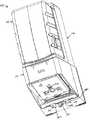
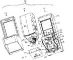
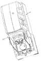
本発明の第一の好ましい態様による、ディスペンサアセンブリ10を示した図1について説明する。ディスペンサアセンブリ(図2が最も分かりやすい)は、背板アセンブリ14、押さえ部材15及び囲い板(シュラウド)16を組み合わせることによって形成されるハウジングに固定されるように適合されている離脱可能なリザーバアセンブリ12を含んでいる。図9に見られるように、背板アセンブリ14は、リザーバ支持ブリッジ200、背板前部ハウジング202、背板後部ハウジング204、バッテリーパック206及び作動ユニット48を含んでいる。上記バッテリーパック206及び作動ユニット48は、背板前部ハウジング202及び背板後部ハウジング204を組み合わせたときに間に形成される、閉じられた区画の内部に収容される。電線208は、バッテリーパック206内のバッテリーと、作動ユニット48内の電子的/電気的部品とを電気的に接続する。Referring to FIG. 1 illustrating adispenser assembly 10 according to a first preferred embodiment of the present invention. A dispenser assembly (FIG. 2 is most obvious) is a removable reservoir assembly adapted to be secured to a housing formed by combining aback plate assembly 14, aretainer member 15 and ashroud 16. 12 is included. As seen in FIG. 9, thebackplate assembly 14 includes areservoir support bridge 200, a backplatefront housing 202, a backplaterear housing 204, abattery pack 206 and anactuation unit 48. Thebattery pack 206 and theoperating unit 48 are accommodated in a closed compartment formed when the backplate front housing 202 and the back platerear housing 204 are combined. The electric wire 208 electrically connects the battery in thebattery pack 206 and the electronic / electrical components in theoperation unit 48.

図2について説明する。リザーバ支持ブリッジ200は、背板前部ハウジング202の、概前方に向いている面板17上に支持されている。そこから上記支持ブリッジ200の、水平に配置された支持板18が前方に延出しており、支持板18は2つの側壁19によって支持されている。上記側壁19には、それぞれ軸受21があり、スタブアクスル20がその軸受21に収容されることで、押さえ部材15は、2つの側壁19の間で上記支持ブリッジ200に枢着されている。囲い板16を背板アセンブリ14に結合させ、支持ブリッジ200と押さえ部材15を実質的に纏着することによって上記ハウジングは完成する。リザーバアセンブリ12のポンプアセンブリ25のピストン32が、押さえ部材15と結合することによって、リザーバアセンブリ12は組み立て後のハウジングに対し離脱可能に結合できるようなっている。With reference to FIG. Thereservoir support bridge 200 is supported on theface plate 17 of the backplate front housing 202 facing generally forward. From there, thesupport plate 18 of thesupport bridge 200 arranged horizontally extends forward, and thesupport plate 18 is supported by twoside walls 19. Eachside wall 19 has abearing 21, and the stub axle 20 is accommodated in thebearing 21, whereby thepressing member 15 is pivotally attached to thesupport bridge 200 between the twoside walls 19. The housing is completed by coupling theshroud 16 to thebackplate assembly 14 and substantially attaching thesupport bridge 200 and the pressingmember 15 together. Thepiston 32 of thepump assembly 25 of thereservoir assembly 12 is coupled to theholding member 15 so that thereservoir assembly 12 can be detachably coupled to the assembled housing.

作動ユニット
図4、9〜12及び15において最もわかるように、背板アセンブリ14は作動ユニット48を備え、担持している。図11において概略的に示すように、上記作動ユニット48は、一連のギア50を介して駆動輪51を回転させる電気モータ49を含んでいる内部駆動アセンブリを備えている。駆動輪51は、偏心軸を持つように、かつ軸方向外方に延出するように設けられているカムポスト52を備えている。カムポスト52は、駆動輪51が回転すれば一全旋回するように、上記押さえ部材15の内側端部と結合しており、上記押さえ部材15は、スタブアクスル20を中心に下側に、次に上側に回転して、元の同じ位置に戻る。押さえ部材15は、上記リザーバアセンブリ12のポンプアセンブリ25のピストン32と結合している。
Actuation Unit As best seen in FIGS. 4, 9-12 and 15, thebackplate assembly 14 includes and carries anactuation unit 48. As shown schematically in FIG. 11, theactuation unit 48 includes an internal drive assembly that includes an electric motor 49 that rotates adrive wheel 51 through a series ofgears 50. Thedrive wheel 51 includes acam post 52 that has an eccentric shaft and extends outward in the axial direction. Thecam post 52 is coupled to the inner end portion of thepressing member 15 so that thecam post 52 rotates completely when thedriving wheel 51 rotates. Rotate upward to return to the same original position. Theholding member 15 is coupled to thepiston 32 of thepump assembly 25 of thereservoir assembly 12.

一回転作動するうちに、上記モータ49は、駆動輪51を360度回転するように作動させ、これにより押さえ部材15が動く。その結果、上記ピストン32が、内側に、次に外側に一ストローク動き、リザーバアセンブリのボトル22から、ピストン32の吐出口34を介して外へ、ある所定量の液体が吐出される。上記モータ49は電気モータであり、また種々の入力情報を受け取る制御機構によってその作動が制御されるものでもよい。During the one-turn operation, the motor 49 operates thedrive wheel 51 to rotate 360 degrees, whereby the pressingmember 15 moves. As a result, thepiston 32 moves one stroke inward and then outward, and a predetermined amount of liquid is discharged from thebottle 22 of the reservoir assembly to the outside through thedischarge port 34 of thepiston 32. The motor 49 is an electric motor, and its operation may be controlled by a control mechanism that receives various input information.

図示されている作動ユニット48は、ディスペンサの作動が非接触式で行われるようになっており、図4に見られるように、使用者の手210が吐出口34の真下にあると手感知システムによって感知される。上記手感知システムは、作動ユニット48の前底部にあり、使用者の手210が差し出される位置に向けて下方かつ前方に放射線を向ける電磁放射線エミッタ53と、作動ユニット48の前底部にあり、使用者の手によって反射された放射線を感知する電磁放射線センサ54を備えている。手から反射された放射線を適切に受波した際には、上記手感知システムは、手の存在を示す適切な信号、例えばモータを作動させるための少なくともひとつの条件を満足する信号、を制御機構に送る。The illustratedactuating unit 48 is such that the dispenser is operated in a non-contact manner and, as seen in FIG. 4, the hand sensing system when the user'shand 210 is directly under theoutlet 34. Perceived by. The hand sensing system is located at the front bottom of theactuation unit 48 and is located at the front bottom of theactuation unit 48; anelectromagnetic radiation emitter 53 that directs radiation downward and forward toward the position where the user'shand 210 is extended; Anelectromagnetic radiation sensor 54 that senses radiation reflected by the user's hand is provided. When the radiation reflected from the hand is properly received, the hand sensing system controls the appropriate signal indicating the presence of the hand, for example, a signal that satisfies at least one condition for operating the motor. Send to.

作動ユニット48は、図11の絵画図法による分解図において概略的に示されている。作動ユニット48は、底214と嵌合するふた蓋212を有しており、嵌合されることによって、内部に回路基盤216及び内部駆動アセンブリ218、ならびにキャリッジ部材220を載置するための、実質的に閉じられた内部区画がその間にできる。モータ49は、回路基盤216に電気的に接続できるように載置されている。種々のギア50は、その各端部が、ふた212、底214、回路基盤を貫通するように設けられた適当な開口部によって軸支されており、かつ、例えばふた212を通してギア50のひとつが駆動輪51に結合することにより、該駆動輪51を保持し、回転させるようになっている。該回路基盤216は、手感知システムのエミッタ53とセンサ54を備えている。該エミッタ53とセンサ54は、可撓性配線223及び224によって該回路基盤に電気的に接続されている。キャリッジ部材220は、2つの概円筒形ソケット225及び226を備えている。該ソケット225及び226には上記エミッタ53と上記センサ54がそれぞれ固定された状態で収容できるようになっており、上記エミッタ53と上記センサ54は、ソケット225及び226の一つに同軸向きに収容される。Theactuation unit 48 is shown schematically in the exploded view according to the pictorial projection of FIG. The actuatingunit 48 has alid lid 212 that mates with thebottom 214 and is substantially mated to mount thecircuit board 216 andinternal drive assembly 218 andcarriage member 220 therein. A closed interior compartment is created in the meantime. The motor 49 is placed so that it can be electrically connected to thecircuit board 216. Thevarious gears 50 are pivotally supported at each end by a suitable opening provided through thelid 212, thebottom 214, the circuit board, and one of thegears 50 is for example through thelid 212. By coupling to thedriving wheel 51, thedriving wheel 51 is held and rotated. Thecircuit board 216 includes anemitter 53 and asensor 54 of a hand sensing system. Theemitter 53 andsensor 54 are electrically connected to the circuit board byflexible wires 223 and 224. Thecarriage member 220 includes two generallycylindrical sockets 225 and 226. In thesockets 225 and 226, theemitter 53 and thesensor 54 can be accommodated in a fixed state. Theemitter 53 and thesensor 54 are accommodated coaxially in one of thesockets 225 and 226. Is done.

図12で最も分かるように、組み立て後のキャリッジ部材は、その各端部に、一対のスタブアクスル228を有している。該一対のスタブアクスル228は同軸方向に配置されており、円筒状の外側に向いた軸面となる。ふた212は、内向きのソケット232を備えた側壁230を有している。上記ソケット232には、キャリッジ部材がふた212に軸受されて、キャリッジ部材が234で示した一般軸(general axis)を中心に回転するように、上記キャリッジ部材のスタブアクスル228が収容されている。スタブアクスル228は、ふた212と底214を共に嵌着した時に、底214の前壁236の部分によってソケット232の開口端が閉じられることで、ソケット232内に動かないように保持される。As best seen in FIG. 12, the assembled carriage member has a pair ofstub axles 228 at each end thereof. The pair ofstub axles 228 are arranged in a coaxial direction, and form a cylindrical surface facing outward. Thelid 212 has aside wall 230 with aninward socket 232. Thesocket 232 accommodates astub axle 228 of the carriage member such that the carriage member is supported by thelid 212 and the carriage member rotates about a general axis indicated by 234. When thelid 212 and the bottom 214 are fitted together, thestub axle 228 is held so as not to move in thesocket 232 because the open end of thesocket 232 is closed by the portion of thefront wall 236 of the bottom 214.

キャリッジ部材220は、スタブアクスル228に対して平行に延びている支持柱238を有している。支持柱238にはソケット225及び226が一緒に設けられている。キャリッジ部材220に結合されている離脱可能なハンドル部材240が示されている。ハンドル部材240は、支持柱238から前方に延びており、2つのソケットの中央にあって、スタブアクスル228を通る軸441に対して相対的に放射状に延びている。一対の把持アーム242は、支持柱238から放射状に延びており、ハンドル部材240のいずれかの側で互いに空間的に離れて配置されているが、但しスタブアクスル228の軸441に対する角度は、ハンドル部材240のものとは異なっている。把持部材242は、それぞれ、支持柱238に結合している内側の端部から、遠位端244にまで延出している。把持アーム242は、その端部244の近傍に、内側に延出した半球状の凸部245を備えている。底214の前壁236は、一対の側面248を有する位置決めブリッジ246を備えている。その側面248は、それぞれ一列の半円状凹部250を有しており、一列の半円状の凹部は、ふた212が底214に嵌合された時の回転軸234を軸とする円弧内の異なる位置に配置されている。図10に示す組み立て後の作動ユニット48においては、作動ユニット48と、回転軸234を軸として回転するようソケット内に軸受けされたキャリッジ部材220が図示されている。図10においては、把持アーム242は、位置決めブリッジ246の各側面248から外向きに配置されている。把持アーム242は凹部250のいずれか一つに収容されるように調整されている凸部245を有しており、それによりキャリッジ部材220が、軸234を中心とした数多くの異なる回転位置の一つに位置決めされる。図10と15において、一列の凹部250は3つの凹部を含んでおり、キャリッジ部材220は凹部250の真ん中に位置するように示されている。Thecarriage member 220 has asupport column 238 that extends parallel to thestub axle 228. Thesupport column 238 is provided withsockets 225 and 226 together. Aremovable handle member 240 coupled to thecarriage member 220 is shown. Thehandle member 240 extends forward from thesupport post 238 and extends radially relative to an axis 441 through thestub axle 228 at the center of the two sockets. The pair of grippingarms 242 extend radially from thesupport column 238 and are spaced apart from each other on either side of thehandle member 240, except that the angle of thestub axle 228 relative to the axis 441 is Different from that ofmember 240. Each grippingmember 242 extends from an inner end coupled to thesupport post 238 to the distal end 244. Thegrip arm 242 includes a hemisphericalconvex portion 245 extending inward in the vicinity of the end portion 244 thereof. Thefront wall 236 of the bottom 214 includes apositioning bridge 246 having a pair of side surfaces 248. Each of the side surfaces 248 has a row ofsemicircular recesses 250, and the row of semicircular recesses is in an arc around therotation axis 234 when thelid 212 is fitted to the bottom 214. They are located at different positions. In the assembledoperation unit 48 shown in FIG. 10, theoperation unit 48 and thecarriage member 220 that is supported in the socket so as to rotate about therotation shaft 234 are illustrated. In FIG. 10, thegrip arm 242 is disposed outward from eachside surface 248 of thepositioning bridge 246. Thegripping arm 242 has aconvex portion 245 that is adjusted to be received in any one of theconcave portions 250 so that thecarriage member 220 can be in one of a number of different rotational positions about theshaft 234. Positioned in one. 10 and 15, the row ofrecesses 250 includes three recesses, and thecarriage member 220 is shown positioned in the middle of therecesses 250.

図1に見られるように、上記離脱可能なハンドル240は、上記キャリッジ部材220に結合されたときには前方に延びており、取付け者の手で掴めるように、またある一対の凹部250から、他の対の凹部へと凸部245を強制的に移動させることができるように適合されている。As can be seen in FIG. 1, theremovable handle 240 extends forward when coupled to thecarriage member 220 and can be grasped by the installer's hand and from one pair ofrecesses 250 to the other. Theprotrusion 245 is adapted to be forcibly moved to the pair of recesses.

エミッタ53は、概指向性となるように、すなわち、電磁放射線が長手方向のエミッタ軸253に概平行にエミッタから外側に放射されるよう概ね設計されているランプを有している。同様に、図14に見られるように、上記センサは、該センサで終端する長手方向のセンサ軸254に概平行に放射された放射線を感知する、概指向性のものである。ソケット255と256は、それぞれ、それを通過しようとするあらゆる電磁放射線の伝達を実質的に防ぐのを援助する囲い板(シュラウド)として効果的に作用し、放射線の放射または受波のいずれかをソケット255及び256の外側端を通過するもののみに制限するよう、上記エミッタ53とセンサ54の指向性を高めるのに効果的に作用する。エミッタ軸253とセンサ軸254は、回転軸234を含む共通平面状に配置されている。上記回転軸234とは、その軸を中心としてキャリッジ部材220が、作動ユニット48に軸受けされている軸である。同様に、ハンドル240は、実質的に同じ共通平面内に延出しているように示されている。エミッタ軸253及びセンサ軸254は、上記回転軸234を含む面内で収束するよう、互いに角度が異なった状態で配置されており、収束点は回転軸234から一定の距離にある。上記エミッタ軸253と上記センサ軸254は、それぞれ上記回転軸234に対して同一の相対角度となるよう配置されていることから、上記収束点は、ソケット225と226の間の中央に位置している。このような構成は、必須ではないものの、ディスペンサ上の配置や配列を対照的にする上で好ましいものである。Theemitter 53 has a lamp that is generally designed to be generally directional, that is, electromagnetic radiation is emitted outwardly from the emitter generally parallel to thelongitudinal emitter axis 253. Similarly, as seen in FIG. 14, the sensor is generally directional, sensing radiation emitted generally parallel to alongitudinal sensor axis 254 terminating at the sensor. Sockets 255 and 256 each effectively act as a shroud that helps to substantially prevent transmission of any electromagnetic radiation that attempts to pass through, and either emit or receive radiation. It works effectively to enhance the directivity of theemitter 53 and thesensor 54 so as to limit the passage to the outer ends of the sockets 255 and 256. Theemitter shaft 253 and thesensor shaft 254 are arranged in a common plane including therotation shaft 234. Therotary shaft 234 is a shaft on which thecarriage member 220 is supported by theoperation unit 48 with the shaft as a center. Similarly, thehandle 240 is shown extending in substantially the same common plane. Theemitter shaft 253 and thesensor shaft 254 are arranged at different angles so as to converge within the plane including therotation shaft 234, and the convergence point is at a certain distance from therotation shaft 234. Since theemitter shaft 253 and thesensor shaft 254 are arranged at the same relative angle with respect to therotation shaft 234, the convergence point is located at the center between thesockets 225 and 226. Yes. Such a configuration is not essential, but is preferable for contrasting the arrangement and arrangement on the dispenser.

図15について説明する。側面から見た図の中に矢印262が示されているが、これは把持アーム242が中央の凹部250内に凸部を介して挿着されている時の、上記エミッタ軸253と上記センサ軸254をそれぞれ含む共通面である。矢印261及び263は、それぞれ、把持部材242が最下部、及び最上部の凹部250にそれぞれ嵌合されている状態でキャリッジ部材220が回転した場合の、この共通面の位置を示している。FIG. 15 will be described. An arrow 262 is shown in the drawing viewed from the side, and this indicates that theemitter shaft 253 and the sensor shaft when thegripping arm 242 is inserted into the centralconcave portion 250 via the convex portion. It is a common surface including 254 respectively. Arrows 261 and 263 indicate the positions of the common surface when thecarriage member 220 rotates with the grippingmember 242 fitted in the lowermost and uppermostconcave portions 250, respectively.

図13について説明する。図13は、上部部品270と下部部品271から形成されるキャリッジ部材220を示している。上部部品270上には、下部部品271内の開口部273に通してスナップ嵌めするための留め具272があり、上部部品270と下部部品271を合わせて共にスナップ嵌めできるように適合されている。上部部品270は、スタブアクスル222の半分を備えており、一方、下部部品271はもう片方の半分を備えている。同様に、上部部品270は、ソケット225の上側半分と、ソケット226の上側半分を備えており、下部部品271はソケット225の下側半分と、ソケット226の下側半分を備えている。上記上部270と上記下部271をスナップ嵌めする際には、エミッタ53はソケット225内に、動かないように同軸方向に収容され、センサ54は、ソケット226内に、動かないように同軸方向に収容される。FIG. 13 will be described. FIG. 13 shows acarriage member 220 formed from an upper part 270 and a lower part 271. On the upper part 270 there is a fastener 272 for snap-fitting through an opening 273 in the lower part 271, adapted to snap together the upper part 270 and the lower part 271. The upper part 270 comprises half of the stub axle 222, while the lower part 271 comprises the other half. Similarly, the upper part 270 includes an upper half of thesocket 225 and an upper half of thesocket 226, and the lower part 271 includes a lower half of thesocket 225 and a lower half of thesocket 226. When the upper part 270 and the lower part 271 are snap-fitted, theemitter 53 is accommodated in thesocket 225 in a coaxial direction so as not to move, and thesensor 54 is accommodated in thesocket 226 in a coaxial direction so as not to move. Is done.

図15内の矢印261、262及び263によって示されている、上側位置、中央位置、又は下側位置のいずれかの位置を採るようキャリッジ部材220を位置決めすることにより、手検出システムの、吐出口34の下側に位置する調理台などの常設の物からの不本意な反射を避けるための能力を変えることができる。同様に、例えば、図15に示したような、矢印262で表される中央位置にキャリッジ部材がある場合に、吐出口34の下側には、手が差し出され、感知されるのに好ましい位置及び距離があるであろう。しかしながら、ある環境においては、例えば、ディスペンサの下に調理台があるせいで、調理台の上部の位置に差し出された手を感知する能力が制限されるような環境においては、例えば、より高い位置にある手の感知をより容易にする、矢印261によって表された位置に相当する位置へとキャリッジ部材を移動させたほうが有利である。同様に、ある環境においては、壁面上のかなり高い位置以外にディスペンサを設置することが困難な場合がある。その場合、ディスペンサを使う人間は、吐出ノズル34のかなり下の位置に手を差し出しがちである。このような場合には、キャリッジ部材220を矢印263によって示されている位置に相当する位置に置くことによって、吐出口下方のより低い位置にある手を感知しやすくすることができる。The outlet port of the hand detection system by positioning thecarriage member 220 to take one of the upper, middle or lower positions indicated by arrows 261, 262 and 263 in FIG. The ability to avoid unintentional reflections from permanent objects such as acountertop 34 can be changed. Similarly, for example, when the carriage member is at the center position represented by the arrow 262 as shown in FIG. 15, it is preferable that the hand is inserted and sensed below thedischarge port 34. There will be location and distance. However, in some circumstances, for example, in environments where the ability to sense a hand placed in the upper position of the cooking table is limited due to the cooking table under the dispenser, for example, higher It is advantageous to move the carriage member to a position corresponding to the position represented by the arrow 261 that makes it easier to sense the hand in position. Similarly, in certain circumstances, it may be difficult to install the dispenser other than a fairly high position on the wall. In that case, the person using the dispenser tends to put his hand to a position considerably below thedischarge nozzle 34. In such a case, by placing thecarriage member 220 at a position corresponding to the position indicated by the arrow 263, it is possible to easily sense a hand at a lower position below the discharge port.

図5について説明する。図5において、キャリッジ部材220としては、上記センサ54が、実質的に鉛直方向下向き、好ましくは鉛直方向から約10度以内を向くように配置できるものが一般的に好ましい。これは、吐出口34の下側に手が差し出される前には吐出が全く起こらないような、良好な感知がなされる点で好ましいと考えられる。しかしながら、提供されうる限りにおいて、例えばディスペンサの下方にある反射性の調理台のような、ある種の表面が設置されている場合、エミッタからの放射線が該表面で跳ね返ってセンサの方へ反射される可能性があり、その結果、使用者の手が吐出口34の下にないのに誤作動するような問題が起こる。キャリッジ部材220の角度を増大方向に調節する、例えば鉛直方向に対し15度、若しくは20度、若しくは25度、若しくは30度、若しくは35度、又はその間の範囲の任意の角度へと角度を増大させるように調整することで、平面状の調理台表面等からの反射に伴う問題点を減らすことができ、典型的にはなくすことができる。本発明は、ディスペンサが壁面上に設置された場合に、もし反射などによる誤作動に伴う問題があれば、鉛直方向に対するセンサの相対角度を変更でき、その角度を適切な方向に向けることができる便利な配置を提供するものである。FIG. 5 will be described. In FIG. 5, it is generally preferable that thecarriage member 220 can be disposed so that thesensor 54 faces substantially downward in the vertical direction, preferably within about 10 degrees from the vertical direction. This is considered preferable in that good sensing is performed such that no discharge occurs before the hand is pushed out below thedischarge port 34. However, as far as it can be provided, if some kind of surface is installed, for example a reflective cooking table below the dispenser, the radiation from the emitter will bounce off the surface and be reflected back towards the sensor. As a result, there arises a problem that the user's hand is not under thedischarge port 34 and malfunctions. Adjust the angle of thecarriage member 220 in an increasing direction, for example, increase the angle to 15 degrees, or 20 degrees, or 25 degrees, or 30 degrees, or 35 degrees relative to the vertical, or any angle in the range By adjusting in this way, problems associated with reflection from the surface of a flat cooking table or the like can be reduced, and typically can be eliminated. When the dispenser is installed on the wall surface, the present invention can change the relative angle of the sensor with respect to the vertical direction and direct the angle to an appropriate direction if there is a problem with malfunction due to reflection or the like. It provides a convenient arrangement.

センサを向ける角度は、好ましくは5度から約35度の範囲、より好ましくは約10度から約30度の範囲であると考えられる。好ましい実施形態においては、キャリッジ部材220は鉛直方向から10度、20度及び30度の角度に位置することができるようにしている。複数の凹部は、所望の複数の異なる角度に合致するものであるのが好ましい。It is believed that the angle at which the sensor is directed is preferably in the range of 5 degrees to about 35 degrees, more preferably in the range of about 10 degrees to about 30 degrees. In a preferred embodiment, thecarriage member 220 can be positioned at angles of 10, 20, and 30 degrees from the vertical direction. The plurality of recesses preferably match a desired plurality of different angles.

上記収束点を必ずしも手が差し出される場所に配置する必要はなく、また手の上方もしくは下方に配置する必要もない。手感知システムを適切に作動させるためには、単にエミッタ53からの放射線が、手で適切に反射されて、センサ54によって受波されれば充分である。回転可能なキャリッジ部材220は、ディスペンサに対して相対的に異なる場所や位置にある手を最適条件で感知できるよう、及び/又はディスペンサの周辺環境にある常設物からの放射線の反射に伴う問題点を回避できるよう、手感知システムを容易に調節できる簡易な機構を提供する。It is not always necessary to place the convergence point at a place where the hand is extended, and it is not necessary to place the convergence point above or below the hand. In order for the hand sensing system to work properly, it is sufficient that the radiation from theemitter 53 is simply reflected by the hand and received by thesensor 54. Therotatable carriage member 220 is capable of optimally sensing hands at different locations and positions relative to the dispenser and / or associated with the reflection of radiation from permanent objects in the environment surrounding the dispenser. A simple mechanism that can easily adjust the hand sensing system is provided.

図13及び14に最もよく示されている好ましい態様において、ハンドル部材240はキャリッジ部材220とは別個の、離脱可能な要素であり、キャリッジ部材の一部を一体的に形成するものではない。この点に関して、ハンドル部材240は伸長部300を有しており、該伸長部からは、一方の端部において、鍵部材302のような伸長プラグが、長手方向に伸びている。図14に見られるように、鍵部材302は長方形の断面形状を有しており、相補的な鍵穴304の内側にはめ込むことができる寸法となっている。鍵部材302が鍵穴304にはめ込まれた状態では、ハンドル部材240は、図14に示される概念上の長軸276を中心として伸びている。概念上の長軸276は、上記エミッタ軸253と上記センサ軸254間の中心にあり、これらは全て上記共通平面上にある。発明の説明を容易にするために、図1〜4,8〜12及び15の各図中では、上記離脱可能なハンドル部材240はキャリッジ部材と結合しているように示されている。但し、ディスペンサの使用時においては上記ハンドル部材240は取り外されている方が好ましいはずである。上記ハンドル部材240は必須のものではなく、ハンドル部材240を省くことも可能で、キャリッジ部材を手で動かすための他の位置調整機構を有していてもよい。また例えばドライバーや、円筒状の鉛筆の端部などの道具を使って、キャリッジ部材にアクセスできるようになっていてもよい。図14から分かるように、例えばハンドル部材240が取り外されて、マイナスドライバーが支持柱238内の鍵穴304に挿入されていてもよい。In the preferred embodiment best shown in FIGS. 13 and 14, thehandle member 240 is a separate element that is separate from thecarriage member 220 and does not form part of the carriage member. In this regard, thehandle member 240 has anextension 300 from which an extension plug, such as the key member 302, extends in the longitudinal direction at one end. As shown in FIG. 14, the key member 302 has a rectangular cross-sectional shape and is dimensioned to fit inside thecomplementary keyhole 304. In a state in which the key member 302 is fitted in thekey hole 304, thehandle member 240 extends about the conceptuallong axis 276 shown in FIG. A conceptualmajor axis 276 is at the center between theemitter axis 253 and thesensor axis 254, all of which are on the common plane. For ease of explanation of the invention, in each of FIGS. 1-4, 8-12 and 15, theremovable handle member 240 is shown as being coupled to a carriage member. However, it is preferable that thehandle member 240 is removed when the dispenser is used. Thehandle member 240 is not essential, thehandle member 240 can be omitted, and another position adjusting mechanism for moving the carriage member by hand may be provided. Further, the carriage member may be accessible by using a screwdriver or a tool such as an end of a cylindrical pencil. As can be seen from FIG. 14, for example, thehandle member 240 may be removed and a flathead screwdriver may be inserted into thekeyhole 304 in thesupport column 238.

図1及び図9について説明する。背板前部ハウジング202は、その下側の壁284に3つの開口部281、282、283を有している。この開口部はそれぞれ、ソケット225、ハンドル240、及びソケット226と相補関係にある。上記開口部281と283は、ソケット225及び226の下部に配置されており、キャリッジ部材がどのような所望の回転位置にあってもエミッタ53からの放射線が外向きに通過でき、センサ54への放射線が内向きに通過できるサイズとなっている。同様に、開口部282は、ハンドル部材240を挿通することができる開口部となる。ハンドル部材240は、ハンドル部材240を手ではめ込んで、かつ手で操作できるように、該開口部を通じて延出していてもよい。また開口部282があることにより、ハンドル部材240を用いて、所望の回転位置にまでキャリッジ部材220を自在に動かせるようになる。ハンドル部材240を省いてもよい場合に限っては、中央の開口部282は、キャリッジ部材220にはめ込むための道具のアクセス点となってもよい。1 and 9 will be described. The back platefront housing 202 has threeopenings 281, 282, 283 in thelower wall 284 thereof. The openings are complementary tosocket 225, handle 240, andsocket 226, respectively. Theopenings 281 and 283 are disposed below thesockets 225 and 226 so that the radiation from theemitter 53 can pass outward regardless of the desired rotational position of the carriage member, and thesensor 54 The size allows radiation to pass inward. Similarly, theopening 282 is an opening through which thehandle member 240 can be inserted. Thehandle member 240 may extend through the opening so that thehandle member 240 can be snapped in and operated by hand. Further, since theopening 282 is provided, thecarriage member 220 can be freely moved to a desired rotational position using thehandle member 240. Only if thehandle member 240 may be omitted, thecentral opening 282 may serve as an access point for a tool to fit into thecarriage member 220.

背板前部ハウジング202の面板17は、開口部285を有している。この開口部を通して、作動ユニット48内のギア50と嵌合できるよう、駆動輪51が延出していてもよい。Theface plate 17 of the back platefront housing 202 has anopening 285. Thedrive wheel 51 may extend through the opening so that it can be engaged with thegear 50 in theoperation unit 48.

上記面板17は、さらに2つの開口部286と287を有している。上記開口部286と287は作動ユニットのふた212上に備えられたキーシュラウド57と58を収容し、また以下に述べる、オプションのキーシステムの、キーエミッタ55とキーセンサ56を収容する。Theface plate 17 further has twoopenings 286 and 287. Theopenings 286 and 287 contain key shrouds 57 and 58 provided on theactuating unit lid 212 and also contain thekey emitter 55 andkey sensor 56 of the optional key system described below.

好ましい実施形態においては、上記把持アーム上の上記凸部と、ブリッジング部材内の上記凹部の間で嵌合することにより、上記センサを複数の異なる角度に調整できる、キャリッジ部材の不連続型プリセット位置合わせ機構となる。好ましくは、上記機構は、例えば保持ブリッジの側面との摩擦力のみによって係合している把持アームを有するものなどにすることにより、ある範囲内における所望の角度に吐出角度を自在に調整できるようアレンジすることができる。In a preferred embodiment, a discontinuous preset of the carriage member, wherein the sensor can be adjusted to a plurality of different angles by fitting between the convex part on the gripping arm and the concave part in the bridging member. It becomes an alignment mechanism. Preferably, the discharge mechanism can be freely adjusted to a desired angle within a certain range by using, for example, a mechanism having a gripping arm engaged only by a frictional force with the side surface of the holding bridge. Can be arranged.

好ましい実施形態においては、上記ソケット部材225及び226は、キャリッジ部材に対して動かないように固定されている。しかしながら、キャリッジ部材は、ソケット部材225と226が互いに収束し合う角度が変更できるようなアレンジを備えるよう、さらに改変することもできる。必須ではないが、上記ソケット部材225及び226は、ソケットを動かしても必ず上記回転軸に対して対称のままであるのが好ましい。In a preferred embodiment, thesocket members 225 and 226 are fixed so as not to move relative to the carriage member. However, the carriage member can be further modified to provide an arrangement that allows the angle at which thesocket members 225 and 226 converge to each other to be changed. Although not essential, it is preferable that thesocket members 225 and 226 always remain symmetrical with respect to the rotation axis even when the socket is moved.

リザーバアセンブリ
図5で最も良く分かるように、リザーバアセンブリ12は、リザーバボトル22と、ポンプアセンブリ25と、キーカラー26を備えている。上記ボトル22は、出口28を中心にねじ山付ネック27を有している。ロッキングタブ29は、ねじ山付ネック27に対して相対的に前方かつ軸方向に延在しており、水平に切ったときの軸方向の断面形状は概長方形で、平坦な平行状の側面と、それらに垂直な端面を有している。上記ポンプアセンブリ25は、外部フランジ31を有するピストンチャンバー形成部材30を備える。その内側にはねじ部が設けられており、外部フランジ31が、ねじ山付ネック27に螺合できるようになっている。ポンプアセンブリ25は、ピストン32とバルブ部材33を更に備えている。上記ピストン32はピストンチャンバー形成部材内に形成される円筒状のチャンバー内で、同軸方向に往復運動可能なものである。その往復運動によって、ボトル22の内部から上記出口28の外に出た液体は、上記ピストン32の内部を通って、上記ピストン32の外側端の吐出口34から外へと吐出される。
Reservoir Assembly As best seen in FIG. 5, thereservoir assembly 12 includes areservoir bottle 22, apump assembly 25, and akey collar 26. Thebottle 22 has a threadedneck 27 around anoutlet 28. Thelocking tab 29 extends forward and axially relative to the threadedneck 27 and has a substantially rectangular cross-section in the axial direction when cut horizontally, with a flat parallel side surface and , Have end faces perpendicular to them. Thepump assembly 25 includes a pistonchamber forming member 30 having anouter flange 31. Inside, a threaded portion is provided so that theouter flange 31 can be screwed onto the threadedneck 27. Thepump assembly 25 further includes apiston 32 and avalve member 33. Thepiston 32 can reciprocate in a coaxial direction in a cylindrical chamber formed in a piston chamber forming member. Due to the reciprocating motion, the liquid that has flowed out of theoutlet 28 from the inside of thebottle 22 passes through the inside of thepiston 32 and is discharged to the outside from thedischarge port 34 at the outer end of thepiston 32.

図6に上記ボトル22及びポンプアセンブリ25を組み立てた後の状態を示す。図6に示されているアセンブリに、上記カラー26を軸方向上方にスライドさせることにより装着して、外部フランジ31上にカラー26をスナップ嵌めによって嵌合させ、外部フランジから動けなくし、またロッキングタブ29をカラー26上の溝46に係合させて、ボトル22に対してカラー26が相対的に回転できなくなるようにする。図7に見られるように、カラー26は、軸方向の上端35と、軸方向の下端36と、中央の、概円筒状の開口部37を有しており、カラー26は、その開口部37を通るように延在している。上記開口部37の周囲にある概円筒状の側壁38は、下端36の近傍に、3つの放射状内方に延出している下部ショルダー部材39を備えており、上記下部ショルダー部材39からは上端35に向かって軸方向に向いているストップショルダー80が張出している。上端35の近傍に、上記側壁38は3つの放射方向内側に向いた上部ショルダー部材40を備えている。上記上部ショルダー部材40は、下端36の方向を向いている把持面81と、上端35の方向を向いているベベル(傾斜)カム面(bevelled camming surface)82を有している。外部フランジ31上でカラー26を軸方向上側にスライドさせる際に、上部ショルダー部材40の上記ベベルカム面82は、上記外部フランジ31の外側下部面83にかみ合い、上部ショルダー部材40を放射方向外側へと押しやることにより、外部フランジ31は、カラー26に対して軸方向に、下端36に向かって、カラー26の開口部37内へと動かすことができるようになる。一旦外部フランジ31の上端84が上部ショルダー部材40の下に位置すれば、上記上部ショルダー部材40は、元の押し込まれてない位置にまで戻り、把持面81が、上記外部フランジ31の上端84の上方で、放射方向内側に向かって配置されることになり、その結果、下部ショルダー部材39のストップショルダー80と、上部ショルダー部材40の上記把持面81の間で、外部フランジ31をロックすることになる。FIG. 6 shows a state after thebottle 22 and thepump assembly 25 are assembled. Thecollar 26 is mounted on the assembly shown in FIG. 6 by sliding thecollar 26 upward in the axial direction, and thecollar 26 is fitted onto theouter flange 31 by a snap fit so that thecollar 26 cannot move from the outer flange. 29 is engaged with agroove 46 on thecollar 26 so that thecollar 26 cannot rotate relative to thebottle 22. As shown in FIG. 7, thecollar 26 has an axial upper end 35, an axiallower end 36, and a central, generallycylindrical opening 37. Thecollar 26 has anopening 37. It extends to pass through. The generallycylindrical side wall 38 around theopening 37 includes threelower shoulder members 39 extending radially inward in the vicinity of thelower end 36, and the upper end 35 extends from thelower shoulder member 39. Astop shoulder 80 facing in the axial direction is overhanging. In the vicinity of the upper end 35, theside wall 38 includes threeupper shoulder members 40 facing radially inward. Theupper shoulder member 40 has agripping surface 81 facing thelower end 36 and a beveled cam surface 82 facing the upper end 35. When thecollar 26 is slid upward on theouter flange 31 in the axial direction, the bevel cam surface 82 of theupper shoulder member 40 engages with the outerlower surface 83 of theouter flange 31, and theupper shoulder member 40 is moved radially outward. By pushing, theouter flange 31 can be moved axially relative to thecollar 26 toward thelower end 36 and into theopening 37 of thecollar 26. Once theupper end 84 of theouter flange 31 is positioned below theupper shoulder member 40, theupper shoulder member 40 returns to the original non-pushed position, and thegripping surface 81 is positioned on theupper end 84 of theouter flange 31. Theupper flange 31 is disposed radially inwardly, and as a result, theouter flange 31 is locked between thestop shoulder 80 of thelower shoulder member 39 and thegripping surface 81 of theupper shoulder member 40. Become.

カラー26は、その上端35上に、上方に延出した一対のロックタブ45を備えており、その一対のロックタブの間に溝46を備えている。上記溝46は上記ボトル22の上記ロッキングタブ29を緊密に収容できる寸法となっている。上記カラー26を、ボトル22とポンプアセンブリ25の組立体に結合させた時、溝46は、ボトル22上のロッキングタブ29と共に円状に並び、図2に示すように、完全に組み立てられたときに溝46の内部にボトル22上のロッキングタブ29が収容され、これにより上記リザーバアセンブリ12が、カラー26とボトル12の相対的に回転できないようになる。図2に示すリザーバアセンブリ12において、上記ピストンチャンバー形成部材30及びカラー26は、ボトル22に対して動かないように固定されている。すなわち、キーカラー26及びピストンチャンバー形成部材30は、上記ボトル22又はキーカラー26が著しく壊れるか変形する以外では、実質的に動かないよう固定されていることが好ましい。Thecollar 26 is provided with a pair oflock tabs 45 extending upward on the upper end 35 thereof, and agroove 46 is provided between the pair of lock tabs. Thegroove 46 is dimensioned to tightly accommodate thelocking tab 29 of thebottle 22. When thecollar 26 is coupled to the assembly of thebottle 22 and pumpassembly 25, thegrooves 46 are arranged in a circle with the lockingtabs 29 on thebottle 22, and when fully assembled as shown in FIG. A lockingtab 29 on thebottle 22 is accommodated in thegroove 46 so that thereservoir assembly 12 cannot be rotated relative to thecollar 26 and thebottle 12. In thereservoir assembly 12 shown in FIG. 2, the pistonchamber forming member 30 and thecollar 26 are fixed so as not to move with respect to thebottle 22. That is, it is preferable that thekey collar 26 and the pistonchamber forming member 30 are fixed so as not to move substantially except that thebottle 22 or thekey collar 26 is significantly broken or deformed.

カラー26及び/又はポンプアセンブリ25の取り外し又は取り外そうとする試みをどの程度許容するか、またカラー26及び/又はポンプアセンブリ25の取り外し又は取り外そうと試みる際に、ボトル22、キーカラー26若しくはピストンチャンバー形成部材30のうちどれか1つ以上を破壊しなければならない程度をどのようにするかは所望の通り選択することができる。例えば組み立てる時に、上記ボトル22、ピストンチャンバー形成部材30及びカラー26を、接着剤を用いて、または超音波溶接によって、恒久的に固着して一体化させることもできる。The degree to which attempts to remove or remove thecollar 26 and / or pumpassembly 25 are tolerated, and when attempting to remove or remove thecollar 26 and / or pumpassembly 25, thebottle 22,key collar 26 Alternatively, the degree to which one or more of the pistonchamber forming members 30 must be destroyed can be selected as desired. For example, at the time of assembly, thebottle 22, the pistonchamber forming member 30, and thecollar 26 can be permanently fixed and integrated by using an adhesive or by ultrasonic welding.

好ましい実施形態においては、図7において170で部分的にのみ示したように、カラー26の上記内部側壁38には、軸方向に延出したリブと溝とが交互に入れ替わるギザギザ形状が刻まれていてもよい。この形状を有することにより、軸方向に延出したリブと溝とが交互に入れ替わるギザギザ形状を有する、相補的にギザギザが刻まれた上記外部フランジ31の外側表面と、上記側壁38のリブとが咬合する。その結果、カラー26が一旦装着されると、ピストンチャンバー形成部材30の、上記カラー26に対する相対回転がおこらないようになる。In the preferred embodiment, as shown only partially at 170 in FIG. 7, theinner side wall 38 of thecollar 26 has a knurled shape with alternating axially extending ribs and grooves. May be. By having this shape, the outer surface of theouter flange 31 that has a jagged shape in which the ribs and grooves extending in the axial direction are alternately replaced, and the ribs of theside wall 38 are complementary. Bite. As a result, once thecollar 26 is mounted, the pistonchamber forming member 30 does not rotate relative to thecollar 26.

上記背板アセンブリ14と、押さえ部材15と、囲い板16とが組み合わせられ、例えば壁に固定された状態において、上記背板アセンブリ14に対して鉛直方向下向きに、上記リザーバアセンブリ12を、カラー部材26とポンプアセンブリ25と共に動かして、上記支持板18の開口部190を鉛直方向下向きに通し、次にリザーバアセンブリ全体を後方に強く動かして、上記カラー26の上部でかつボトル22の下部ショルダー192の下部に、後部支持部191を嵌め込み、押さえ部材15と結合させる位置に上記ピストン32を配置することによって、組み立て後のリザーバアセンブリ12を、背板アセンブリ14と、押さえ部材15と、囲い板16の組立体に結合させてもよい。その逆に、リザーバアセンブリを前方に引き、次に上方に動かすことで上記リザーバアセンブリ12を取り外すことができる。When theback plate assembly 14, the pressingmember 15, and the surroundingplate 16 are combined and fixed to a wall, for example, thereservoir assembly 12 is connected to the collar member in a vertically downward direction with respect to theback plate assembly 14. 26 and thepump assembly 25 to pass the opening 190 of thesupport plate 18 vertically downward, and then the entire reservoir assembly is moved strongly backwards to the upper part of thecollar 26 and thelower shoulder 192 of thebottle 22. The rear support portion 191 is fitted into the lower portion and thepiston 32 is disposed at a position where the rear support portion 191 is coupled to the pressingmember 15, so that the assembledreservoir assembly 12 can be attached to theback plate assembly 14, the pressingmember 15, and theenclosure plate 16. It may be coupled to the assembly. Conversely, thereservoir assembly 12 can be removed by pulling the reservoir assembly forward and then moving it upward.

押さえ部材15は、該押さえ部材15が備える把持部材(図面に未記載)と、ピストン32上の把持フランジ59とを係合させることで、該ピストン32と結合させる。そのような把持部材及び係合方法は、オファルト(Ophardt)の米国特許第5373970号明細書(出願日1994年12月20日)に記載のものと同様のものでもよい。この米国特許第5373970号明細書は、本願明細書に参照により援用される。そのような係合方法によれば、係合すれば必ず上記リザーバアセンブリ12と、上記背板アセンブリ14が結合される。The holdingmember 15 is coupled to thepiston 32 by engaging a holding member (not shown in the drawing) included in the holdingmember 15 with a holding flange 59 on thepiston 32. Such gripping members and methods of engagement may be similar to those described in U.S. Pat. No. 5,373,970 (Opportunity December 20, 1994). This US Pat. No. 5,373,970 is hereby incorporated by reference. According to such an engagement method, thereservoir assembly 12 and theback plate assembly 14 are coupled to each other whenever they are engaged.

光学キーシステム
上記作動ユニット48は、上記リザーバアセンブリ12が作動ユニット48と適合するものか否か、すなわち、リザーバアセンブリ12が、上記作動ユニット48と共に使用することを許可するための予め選択された基準に適合しているかどうかを決定するための、オプションの光学キーシステムの部分を備えるように示されている。上記作動ユニット48の上記回路基板216は、電磁放射線キーエミッタ55と、電磁放射線キーセンサ56を備えている。上記作動ユニット48のふた21は、その前面の上側部分に一対の中空シュラウド57と58を備えている。上記中空シュラウド57と58は前方に向いている。上記キーエミッタ55は、キーエミッタ55のランプを囲むように概円筒状のシュラウド57に収容され、キーセンサ56は、キーセンサを囲むように概円筒状のシュラウド58に収容される。上記シュラウド57と58は、そこを通過しようとするあらゆる電磁放射線の伝達を実質的に防ぎ、光の放射又は受光を、シュラウド57と58の外端を通過するもののみに制限し、キーエミッタ55とキーセンサ56の指向性を高めるのに効果的に作用する。図4と7において最もよく分かるように、カラー26は、2つのアーム60と61を有している。アーム60と61はカラー26からキーエミッタ55又はキーセンサ56のいずれかに向かって、カラー26から後方に延出している。カラー26は、アーム60の端部にある端面62から、カラー26を通って、アーム61の端部にある端面63(導波管の出口となる)へと至る電磁放射線導波管となる。上記導波管は図7中に破線64として概略的に示してある。上記導波管は、カラー26の上端35近傍で、カラーの外周付近に配置された物質からなるU字型リム65の中を概U字型に延在している。
Optical key system The actuatingunit 48 is a preselected criterion for whether thereservoir assembly 12 is compatible with theactuating unit 48, i.e., allowing thereservoir assembly 12 to be used with theactuating unit 48. Is shown to include an optional optical key system portion for determining whether or not Thecircuit board 216 of the operatingunit 48 includes an electromagnetic radiationkey emitter 55 and an electromagnetic radiationkey sensor 56. Thelid 21 of the operatingunit 48 includes a pair of hollow shrouds 57 and 58 in the upper part of the front surface thereof. The hollow shrouds 57 and 58 face forward. Thekey emitter 55 is accommodated in a substantially cylindrical shroud 57 so as to surround the lamp of thekey emitter 55, and thekey sensor 56 is accommodated in a substantially cylindrical shroud 58 so as to surround the key sensor. The shrouds 57 and 58 substantially prevent transmission of any electromagnetic radiation attempting to pass therethrough, restricting light emission or reception to only those passing through the outer ends of the shrouds 57 and 58, and thekey emitter 55 It effectively works to increase the directivity of thekey sensor 56. As best seen in FIGS. 4 and 7, thecollar 26 has twoarms 60 and 61. Thearms 60 and 61 extend rearward from thecollar 26 toward thekey emitter 55 or thekey sensor 56 from thecollar 26. Thecollar 26 is an electromagnetic radiation waveguide that extends from theend face 62 at the end of thearm 60 to the end face 63 (to be the exit of the waveguide) at the end of thearm 61 through thecollar 26. The waveguide is schematically shown as a broken line 64 in FIG. The waveguide extends in a generally U-shape in aU-shaped rim 65 made of a material disposed near the outer periphery of the collar near the upper end 35 of thecollar 26.

図4について説明する。キーエミッタ55から放射された電磁放射線は入口端面62を経て上記導波管64に入り、電磁放射線は導波管に導かれながらカラー26を通り、出口端面63から電磁放射線は導波管を飛び出して、キーセンサ56によって感知される。上記作動ユニット48は、キー制御システムを備えている。キー制御システムの下では、吐出の前提条件として、キーエミッタ55によって放射された電磁放射線について、上記キーセンサによって感知されたその電磁放射線が、所定の1以上のパラメータに適合するかどうかをみる。限定されるわけではないが、例えば、上記キーエミッタ55が選択された範囲内の波長の電磁放射線を放射したが、その波長範囲の電磁放射線を感知するキーセンサ56が存在しない場合には、モータ49の作動を許可しないようにしてもよい。従って、最もシンプルなケース、例えばボトル22とポンプアセンブリ25は有するが、上記カラー26は有しておらず、導波管も有していないような不適合のリザーバアセンブリ12が背板アセンブリ14に結合されたようなケースでは、キーエミッタ55によって放射された、選択された波長を有する放射線はキーセンサ56に届かないか、あるいはキーセンサ56によって感知されず、上記作動ユニットの上記制御機構は吐出を許可しないであろう。FIG. 4 will be described. The electromagnetic radiation radiated from thekey emitter 55 enters the waveguide 64 through theentrance end face 62, the electromagnetic radiation passes through thecollar 26 while being guided to the waveguide, and the electromagnetic radiation jumps out of the waveguide from theexit end face 63. Thekey sensor 56 senses it. The operatingunit 48 includes a key control system. Under the key control system, as a precondition for ejection, the electromagnetic radiation emitted by thekey emitter 55 is examined to determine whether the electromagnetic radiation sensed by the key sensor meets one or more predetermined parameters. For example, when thekey emitter 55 radiates electromagnetic radiation having a wavelength within a selected range but there is nokey sensor 56 that senses electromagnetic radiation within the wavelength range, the motor 49 is not limited thereto. The operation of may not be permitted. Thus, anon-conforming reservoir assembly 12 that has the simplest case, such as abottle 22 and apump assembly 25 but nocollar 26 and no waveguide, is coupled to thebackplate assembly 14. In such a case, radiation having a selected wavelength emitted by thekey emitter 55 does not reach thekey sensor 56 or is not sensed by thekey sensor 56, and the control mechanism of the operating unit does not allow ejection. Will.

好ましい実施形態においては、上記カラー26は、それを通じて電磁放射線を伝達できるプラスチック材料を射出成形することによって形成されたものであるのが好ましい。当業者に公知の通り、ポリカーボネートプラスチックなどの、電磁放射線伝達性を有する製品を与える種々のプラスチック材料を用いることができる。入口端面62に対して垂直方向を向いており、それゆえ光伝達性カラー26に入射し得る放射線は、導波管の側面を効果的に形成するカラーの外表面上に、比較的低角度で衝突するため、ある程度内部で反射される。カラー26の中へと向いた放射線のある一部分は、U字型外部リム65を周回するようにカラー26を通過し、上記放射線のまたある一部分は、出口端面63に対し実質的に垂直方向に向き、導波管を出て、キーセンサ56によって感知されることになる。In a preferred embodiment, thecollar 26 is preferably formed by injection molding a plastic material through which electromagnetic radiation can be transmitted. As known to those skilled in the art, various plastic materials can be used that provide a product having electromagnetic radiation transmission properties, such as polycarbonate plastic. Radiation that is oriented perpendicular to theentrance end face 62 and thus can enter the light-transmittingcollar 26 is at a relatively low angle on the outer surface of the collar that effectively forms the side of the waveguide. Because it collides, it is reflected to some extent inside. A portion of the radiation directed into thecollar 26 passes through thecollar 26 to circulate around the U-shapedouter rim 65, and another portion of the radiation is substantially perpendicular to theexit end face 63. Direction, exit the waveguide, and will be sensed by thekey sensor 56.

上記カラー26は、全て同じ放射線伝達性能を有する一体の要素として形成されていてもよく、またいくつかの異なる物質から形成されていてもよい。例えば、内部反射を増大させるために、入口端面62と出口端面63を除くカラー26の外部表面、特にリム65の周囲は、反射性物質によって被覆されていてもよい。上記カラー26は、カラーのU字型部分のみ、例えば上記U字型リム65に実質的に対応する部分のみが光伝達性物質を含み、カラーの残りの部分は他のプラスチック材料から形成されていてもよい。Thecollar 26 may be formed as an integral element all having the same radiation transmission performance, or may be formed from several different materials. For example, in order to increase internal reflection, the outer surface of thecollar 26 except for theinlet end face 62 and theoutlet end face 63, particularly around therim 65, may be coated with a reflective material. In thecollar 26, only the U-shaped portion of the collar, for example, only the portion substantially corresponding to theU-shaped rim 65 includes the light transmitting material, and the remaining portion of the collar is formed of another plastic material. May be.

上記カラー26は、その中に1以上の光ファイバーが予め組み込まれるように形成されていてもよい。例えば、この光ファイバーをU字型のリム内部に延在するように配置し、光ファイバーの入口端が入口端面62に現れ、かつ光ファイバーの出口端が出口端面63に現れるようにしてもよい。Thecollar 26 may be formed so that one or more optical fibers are preliminarily incorporated therein. For example, the optical fiber may be arranged so as to extend inside the U-shaped rim so that the entrance end of the optical fiber appears on theentrance end face 62 and the exit end of the optical fiber appears on theexit end face 63.

本発明によれば、上記キーエミッタから放射する上記電磁放射線は、予め選択されたパラメータを参酌して選択しても良い。該パラメータとしては、ある波長範囲内での放射、ある強度範囲内の電磁放射、偏光電磁放射、及びある範囲内の持続時間で、時間・時刻を変えておこなう電磁放射などが挙げられる。According to the present invention, the electromagnetic radiation radiated from the key emitter may be selected in consideration of a preselected parameter. Examples of the parameter include radiation within a certain wavelength range, electromagnetic radiation within a certain intensity range, polarized electromagnetic radiation, and electromagnetic radiation performed at different times and times within a certain range of time.

設けられた導波管は、複数の物性から選択される電磁放射線伝達性を有していてもよく、ある波長範囲のものは伝達するものの、ある波長範囲のものは遮蔽する能力を備えていてもよい。導波管を通って伝達される電磁放射線の強度を制限する能力を、好ましくは導波管の大部分の機能として備えていることが好ましい。上記伝達特性は、第一の波長範囲を有する電磁放射線の伝達は制限するものの、一方、第二の波長範囲を有する電磁放射線の伝達は許可するものであってもよい。The provided waveguide may have an electromagnetic radiation transmission property selected from a plurality of physical properties, and has a capability of shielding a certain wavelength range while transmitting a certain wavelength range. Also good. It is preferable to have the ability to limit the intensity of electromagnetic radiation transmitted through the waveguide, preferably as a function of the majority of the waveguide. The transmission characteristic may limit transmission of electromagnetic radiation having a first wavelength range, while permitting transmission of electromagnetic radiation having a second wavelength range.

用いられる電磁放射線の性質に関し、従来利用可能なセンサ及び/又はエミッタの多くは、可視光スペクトル中の電磁放射線を放射し、感知する際に使用できる。しかしながら、これは必要不可欠なものではなく、可視スペクトル外の電磁放射線を使用することもできる。これは、例えば導波管の一部を備えていてもよいモジュール型要素の性能をマスクするのに有利である。例えば、非可視光の電磁放射線が伝達される仕様になっている限り、モジュール型の導波管要素が青、赤、黄色または黄色などの可視色を有しているように見えようが見えまいが特に関係ないことから、モジュラーユニットの色の有無は模倣者をだます手助けとなり得るであろう。With regard to the nature of the electromagnetic radiation used, many of the sensors and / or emitters that are conventionally available can be used in emitting and sensing electromagnetic radiation in the visible light spectrum. However, this is not essential and electromagnetic radiation outside the visible spectrum can be used. This is advantageous, for example, for masking the performance of modular elements that may comprise part of a waveguide. For example, as long as it is designed to transmit invisible electromagnetic radiation, the modular waveguide element will appear to have a visible color such as blue, red, yellow or yellow. Since there is no particular concern, the presence or absence of the color of the modular unit could help fool the imitator.

好ましい実施形態によれば、回路基板216は、従来のものを上回る簡素化された電子技術とモータ49への電気的接続の簡素さを備えている。手感知システムの要素には上記センサ53と、上記エミッタ54と、キーエミッタ55及びキーセンサ56を備えたオプションのキーシステムとが含まれる。本発明によれば、キーシステムを備えていることは必須ではなく、従って上記ディスペンサにはキーエミッタ55若しくはキーセンサ56、又はそれらのシュラウドがなくてもよく、またカラー26がなくてもよい。開示する実施形態はこれらの構成要素がなくても機能するものであり、例えば図6に示されたもののみを含むリザーバアセンブリを挿入した状態でも機能するであろう。According to a preferred embodiment, thecircuit board 216 has simplified electronics over conventional ones and a simplified electrical connection to the motor 49. Elements of the hand sensing system include thesensor 53, theemitter 54, and an optional key system with akey emitter 55 and akey sensor 56. According to the present invention, it is not essential to have a key system, so the dispenser may not have thekey emitter 55 orkey sensor 56, or their shrouds, and may not have thecollar 26. The disclosed embodiments will function without these components and will function even with a reservoir assembly including, for example, only those shown in FIG.

本発明を好ましい実施形態と共に説明してきたが、当業者であれば多くの改変及び変形を想定できるであろう。本発明を明確にするために、特許請求の範囲が参照される。Although the present invention has been described with preferred embodiments, many modifications and variations will occur to those skilled in the art. In order to clarify the invention, reference is made to the claims.

本発明の第1の好ましい実施形態によるディスペンサアセンブリの絵画図である。1 is a pictorial view of a dispenser assembly according to a first preferred embodiment of the present invention. FIG.図1に示すディスペンサアセンブリの絵画図法による分解図である。FIG. 2 is an exploded view of the dispenser assembly shown in FIG.図2に示すリザーバアセンブリ及び背板アセンブリの、組み立て後を示す絵画図である。FIG. 3 is a pictorial view showing the reservoir assembly and back plate assembly shown in FIG. 2 after assembly.図1及び図3に示すディスペンサのリザーバアセンブリ及び作動ユニットに対する、使用者の手の相対的な位置関係を示す側面からの絵画図法による概略図である。FIG. 4 is a pictorial schematic view from the side showing the relative positional relationship of the user's hand with respect to the reservoir assembly and actuation unit of the dispenser shown in FIGS. 1 and 3.図2及び図3に示すリザーバアセンブリの絵画図法による分解図である。FIG. 4 is a pictorial exploded view of the reservoir assembly shown in FIGS. 2 and 3.図5に示すボトル、バルブ部、ピストンチャンバー形成部材及びピストンを組み立てた状態を示す絵画図である。It is a pictorial diagram which shows the state which assembled the bottle, valve | bulb part, piston chamber formation member, and piston which were shown in FIG.図5に示すカラーの、絵画図法による、上からみた背面図である。FIG. 6 is a rear view of the color shown in FIG.図1に示すディスペンサアセンブリ10の概略を示す、横からみた断面図である。It is sectional drawing seen from the side which shows the outline of thedispenser assembly 10 shown in FIG.図2に示す背板アセンブリの、前から見た絵画図法による分解図である。FIG. 3 is an exploded view of the backboard assembly shown in FIG. 2 as viewed from the front.図9に示す作動ユニットの、背面からの絵画図である。FIG. 10 is a pictorial view from the back of the operating unit shown in FIG. 9.図9に示す作動ユニットの、前から見た絵画図法による分解図である。FIG. 10 is an exploded view of the operating unit shown in FIG.図10に示す作動ユニットの選択された構成部品の、下から見た絵画図法による分解図である。FIG. 11 is an exploded view of selected components of the actuation unit shown in FIG. 10 as viewed from below.図12に示すキャリッジ部材の上部部品と下部部品の、後ろから見た絵画図法による分解図である。FIG. 13 is an exploded view of an upper part and a lower part of the carriage member shown in FIG. 12 as viewed from behind.図11に示す回路基板とキャリッジ部材を組み立てたときの絵画図法による概略図である。It is the schematic by the pictorial projection when the circuit board shown in FIG. 11 and a carriage member are assembled.図4を横から見た概略図である。It is the schematic which looked at FIG. 4 from the side.

符号の説明Explanation of symbols

10 ディスペンサアセンブリ
12 リザーバアセンブリ
14 背板アセンブリ
15 押さえ部材
16 囲い板(シュラウド)
17 面板
18 指示板
19 側壁
20 スタブアクスル
21 軸受
22 ボトル
25 ポンプアセンブリ
26 キーカラー
27 ねじ山付ネック
28 出口
29 ロッキングタブ
30 ピストンチャンバー形成部材
31 外部フランジ
32 ピストン
33 バルブ部材
34 吐出口
35 軸方向の上端
36 軸方向の下端
37 概円筒状の開口部
38 概円筒状の側壁
39 下部ショルダー部材
40 上部ショルダー部材
45 ロックタブ
46 溝
48 作動ユニット
49 電気モータ
50 ギア
51 駆動輪
52 カムポスト
53 電磁放射線エミッタ
54 電磁放射線センサ
55 キーエミッタ
56 キーセンサ
57 キーシュラウド(key shroud)
58 キーシュラウド(key shroud)
59 把持フランジ
60 アーム
61 アーム
62 端面
63 面
64 導波管を概略的に示した破線
65 U字型リム
80 ストップショルダー
81 把持面
82 ベベル(傾斜)カム面(bevelled camming surface)
83 外部フランジ31の外側下部面
84 外部フランジ31の上端
170 溝
190 開口部
191 後部支持部
192 下部ショルダー
200 リザーバ支持ブリッジ
202 背板前部ハウジング
204 背板後部ハウジング
206 バッテリーパック
208 電線
210 使用者の手
212 ふた
214 底
216 回路基盤
218 内部駆動アセンブリ
220 キャリッジ部材
223 配線
224 配線
225 円筒形ソケット
226 円筒形ソケット
228 スタブアクスル
230 側壁
232 ソケット
234 一般軸(回転軸)
236 前壁
238 支持柱
240 ハンドル部材
242 把持アーム(把持部材)
244 遠位端
245 半球状の凸部
246 位置決めブリッジ
248 側面
250 半円状凹部
253 エミッタ軸
254 センサ軸
256 ソケット
261 矢印
262 矢印
263 矢印
270 上部部品
271 下部部品
272 留め具
273 穴
276 概念上の長軸
281 開口部
282 開口部
283 開口部
284 下側の壁
285 開口部
286 開口部
287 開口部
300 伸長部
302 鍵部材
304 鍵穴
441 軸
DESCRIPTION OFSYMBOLS 10Dispenser assembly 12Reservoir assembly 14Back plate assembly 15Holding member 16 Enclosure (shroud)
17Face plate 18Indicator plate 19 Side wall 20Stub axle 21Bearing 22Bottle 25Pump assembly 26Key collar 27 Threadedneck 28Outlet 29Locking tab 30 Pistonchamber forming member 31External flange 32Piston 33Valve member 34 Discharge port 35 Axial direction Upper end 36 Axiallower end 37 Substantiallycylindrical opening 38 Substantiallycylindrical side wall 39Lower shoulder member 40Upper shoulder member 45Lock tab 46Groove 48 Actuating unit 49Electric motor 50Gear 51Drive wheel 52 Cam post 53Electromagnetic radiation emitter 54Electromagnetic Radiation sensor 55Key emitter 56 Key sensor 57 Key shroud
58 key shroud
59 grippingflange 60arm 61arm 62end face 63 face 64broken line 65 schematically showing the waveguide U-shaped rim 80stop shoulder 81 gripping face 82 beveled camming surface
83 Outer lower surface ofouter flange 31 Upper end 170 ofouter flange 31 Groove 190 Opening portion 191Rear support portion 192Lower shoulder 200Reservoir support bridge 202 Back platefront housing 204 Back platerear housing 206 Battery pack 208Electric wire 210 User'shand 212Lid 214Bottom 216Circuit board 218Internal drive assembly 220Carriage member 223Wiring 224Wiring 225Cylindrical socket 226Cylindrical socket 228Stub axle 230Side wall 232Socket 234 General axis (rotating axis)
236Front wall 238Support column 240Handle member 242 Grasping arm (gripping member)
244Distal end 245 Hemisphericalconvex portion 246Positioning bridge 248Side surface 250 Semicircularconcave portion 253Emitter shaft 254 Sensor shaft 256 Socket 261 Arrow 262 Arrow 263 Arrow 270 Upper part 271 Lower part 272 Fastener 273Hole 276 Conceptual length Shaft 281Opening 282Opening 283Opening 284Lower wall 285Opening 286Opening 287Opening 300 Extending portion 302Key member 304 Key hole 441 Shaft

Claims (11)

Translated fromJapanese
使用者の手が、吐出される物質の吐出口(34)の下の適位置にある時に、該手の上に該物質を吐出するための自動吐出装置であって、
前記吐出装置は、鉛直壁に設置するための背板を有しており、
前記吐出装置は、前記背板から前方に突出しており、
前記吐出口は、前記背板から前方に離れる方向へ備えられ、
前記吐出口は、背板に対して固定された吐出軸に沿って、物質を鉛直方向下向きに吐出し、
前記吐出装置は、電磁放射線を放射するエミッタ(53)と、前記吐出口(34)の下の適切に位置する使用者の手によって反射される、該エミッタ(53)によって放射された電磁放射線を感知するためのセンサ(54)を有しており、
キャリッジ部材(220)は、地面と水平であり、該吐出装置の横方向に伸びている回転軸(234)に対して回転する以外は前記吐出装置に対して動かないように固定された前記吐出装置に枢着されており、
前記エミッタ(53)及び前記センサ(54)は前記キャリッジ部材(220)に担持されており、
前記エミッタ(53)は、概指向性であって、長手方向の放射軸(253)に概平行に前記エミッタから外側へ放射線を放射するものであり
前記センサ(54)は、概指向性であって、該センサ内で終端する長手方向の感知軸(254)に概平行に放射された放射線を検知するものであり、
前記放射軸と前記感知軸は、前記回転軸(234)を含む概共通面上に配置され
前記キャリッジ部材は、背板に対して複数の異なる位置間にある前記回転軸を中心に回転できるように前記吐出装置に枢着され、前記異なる位置間にある前記キャリッジ部材が回転すると、前記吐出軸に対して異なる角度方向に前記共通面が配置されていることを特徴とする自動吐出装置。
An automatic discharge device for discharging the substance onto the hand when the user's hand is in an appropriate position below the discharge port (34) of the substance to be discharged,
The discharge device has a back plate for installation on a vertical wall;
The discharge device protrudes forward from the back plate,
The outlet is provided in a direction away from the back plate;
The discharge port discharges the substance vertically downward along a discharge axis fixed to the back plate,
The ejection device emits electromagnetic radiation emitted by the emitter (53) that is reflected by an emitter (53) that emits electromagnetic radiation and a user's hand that is suitably located under the ejection opening (34). A sensor (54) for sensing,
The carriage member (220) is horizontal to the ground, and the discharge member is fixed so as not to move with respect to the discharge device except for rotating with respect to a rotation shaft (234) extending in a lateral direction of the discharge device. Is pivotally attached to the device,
Said emitter (53) and the sensor (54)is supported on the carriage member (220),
The emitter (53) is generally directional and emits radiation outward from the emitter approximately parallel to the longitudinal radiation axis (253), and the sensor (54) is approximately directional. Detecting radiation emitted substantially parallel to a longitudinal sensing axis (254) terminating in the sensor,
The radiation axis and the sensing axis are disposed on a substantially common plane including the rotation axis (234),
The carriage member is pivotally attached to the discharge device so as to be rotatable about the rotation shaft between a plurality of different positions with respect to the back plate, and when the carriage member between the different positions rotates, the discharge member An automatic discharge apparatus, wherein the common surface is arranged in different angular directions with respect to an axis .
前記放射軸(253)と前記検知軸(254)は、前記吐出装置(10)の下の面内にある収束点で交わって収束する請求項1記載の吐出装置。Wherein the radiation axis (253) detection axis (254), the discharge device (10) according to claim1 Symbol placement of the ejection device converge meet at the convergence point in the plane of the bottom of the.前記エミッタ(53)と前記センサ(54)は、前記回転軸(234)に対して平行方向に互いに距離をおいて配置されている請求項1又は2記載の吐出装置。The ejection device according to claim1 or 2, wherein the emitter (53) and the sensor (54) are arranged at a distance from each other in a direction parallel to the rotation axis (234).前記放射軸は、前記回転軸に対する放射角度が一定であり、前記感知軸は、前記回転軸に対する感知角度が一定であり、該感知角度は該放射角度に等しい、請求項1〜のいずれか一項に記載の吐出装置。The radiation axis is the radiation angle is constant with respect to the rotation axis, wherein the sensing axis sensing angle with respect to the rotation axis is constant, the sensing angle is equal to the radiation angle, claim1-3 The discharge device according to one item.記キャリッジ部材(220)が回転すると、前記共通面と吐出軸の交差点が、前記吐出口の下方の異なる相対高さの位置に変わる、請求項1〜のいずれか一項に記載の吐出装置。When thefront Symbol carriage member (220) is rotated, an intersection of the common plane and the discharge axis varies the position of the different relative heights of the lower of the discharge port, the discharge of any one of claims1-4 apparatus.前記吐出装置(10)は、前記吐出装置(10)の下側に枢着されているキャリッジ部材(220)を有しており、該キャリッジ部材(220)は前記共通面を下方かつ前方に向け、使用者の手が所定の位置にあるときに、該共通面が該使用者の手と交差するようにする、請求項1〜のいずれか一項に記載の吐出装置。The discharge device (10) has a carriage member (220) pivotally attached to the lower side of the discharge device (10), and the carriage member (220) faces the common surface downward and forward. when the user's hand is in place, the common surface so as to intersect the hand of said use's apparatus according to any one of claims1-5.前記回転軸に対して角度の異なる位置で前記キャリッジ部材(220)を解放可能にロックする角度調整機構を含む請求項1〜のいずれか一項記載の吐出装置。The ejection device according to any one of claims 1 to5 , further comprising an angle adjustment mechanism that releasably locks the carriage member (220) at a position having a different angle with respect to the rotation shaft.前記キャリッジ部材(220)に対し後方向きに結合されており、使用者が手ではめ込むことが可能で、前記回転軸に対して角度の異なる位置へと前記キャリッジ部材(220)を回転させるための、位置調整部材(240)を備える請求項1〜のいずれか一項記載の吐出装置。It is coupled to the carriage member (220) in a rearward direction, and can be fitted by a user by hand, for rotating the carriage member (220) to a position having a different angle with respect to the rotation axis. the discharge apparatus of any one of claims 1 to7 comprising a positioning member (240).前記位置調整部材は、前記吐出装置の下に、手ではめ込むことができるレバー部材(240)を備えており、
前記レバー部材(240)は、前記キャリッジ部材(220)に結合された際に、前記回転軸に対して放射状に前記キャリッジ部材(220)から突出している、請求項記載の吐出装置。
The position adjusting member includes a lever member (240) that can be manually fitted under the discharge device,
The discharge device according to claim8 , wherein the lever member (240) protrudes radially from the carriage member (220) with respect to the rotation shaft when coupled to the carriage member (220).
吐出させる物質の入ったリザーバ(22)を備えたリザーバアセンブリ(12)と、作動ユニット(48)と、該作動ユニット(48)によって作動可能で、前記吐出口(34)の外側へと該リザーバ(22)から物質を吐出するためのポンプ機構(25)と、
前記エミッタ(53)からの放射線を前記センサ(54)が感知したときに前記吐出装置の作動を許可する制御機構と
を含む、請求項1〜のいずれか一項記載の吐出装置。
A reservoir assembly (12) having a reservoir (22) containing a substance to be discharged, an operating unit (48), operable by the operating unit (48), and to the outside of the discharge port (34); A pump mechanism (25) for discharging a substance from (22);
The ejection device according to any one of claims 1 to9 , further comprising a control mechanism that permits operation of the ejection device when the sensor (54) senses radiation from the emitter (53).
請求項1〜10のいずれか一項記載の吐出装置と、エミッタによって放射される電磁放射線を上方に反射する表面を有する調理台との組合せであって、A combination of the ejection device according to any one of claims 1 to 10 and a countertop having a surface that reflects upward the electromagnetic radiation emitted by the emitter,
前記吐出装置が、使用者の手が吐出口の下方かつ調理台表面の上方に位置するのに十分な間隔で調理台の表面の垂直上方に位置する共通軸に対し、該調理台表面の垂直上方にしっかりと固定して枢着されていることを特徴とする組合せ。The discharge device is perpendicular to the surface of the cooking table with respect to a common axis positioned vertically above the surface of the cooking table at a sufficient interval so that the user's hand is positioned below the discharge port and above the surface of the cooking table. A combination characterized by being firmly fixed upward and pivotally attached.
JP2008207977A2007-08-132008-08-12 Non-contact optical control dispenserActiveJP5301918B2 (en)

Applications Claiming Priority (2)

Application NumberPriority DateFiling DateTitle
CA002597190ACA2597190A1 (en)2007-06-182007-08-13Touchless optically controlled dispenser
CA2,597,1902007-08-13

Publications (2)

Publication NumberPublication Date
JP2009045457A JP2009045457A (en)2009-03-05
JP5301918B2true JP5301918B2 (en)2013-09-25

Family

ID=40509983

Family Applications (1)

Application NumberTitlePriority DateFiling Date
JP2008207977AActiveJP5301918B2 (en)2007-08-132008-08-12 Non-contact optical control dispenser

Country Status (2)

CountryLink
JP (1)JP5301918B2 (en)
CN (1)CN101371763B (en)

Families Citing this family (1)

* Cited by examiner, † Cited by third party
Publication numberPriority datePublication dateAssigneeTitle
CN113802939B (en)*2021-08-252025-05-13江苏欧佩日化股份有限公司 A personal care product anti-pollution and anti-theft bracket

Family Cites Families (5)

* Cited by examiner, † Cited by third party
Publication numberPriority datePublication dateAssigneeTitle
US4722372A (en)*1985-08-021988-02-02Louis Hoffman Associates Inc.Electrically operated dispensing apparatus and disposable container useable therewith
JPH0743465A (en)*1993-07-261995-02-14Saraya Kk Photoelectric sensor
US5851108A (en)*1995-01-171998-12-22Beaudreau Electronics, Inc.Electronic control sensor systems
US5979500A (en)*1999-01-191999-11-09Arichel Technologies, Inc.Duration-indicating automatic faucet
US7621426B2 (en)*2004-12-152009-11-24Joseph KanferElectronically keyed dispensing systems and related methods utilizing near field frequency response

Also Published As

Publication numberPublication date
CN101371763B (en)2012-02-29
JP2009045457A (en)2009-03-05
CN101371763A (en)2009-02-25

Similar Documents

PublicationPublication DateTitle
US20090045221A1 (en)Touchless optically controlled dispenser
CN114504184B (en)Cleaning appliance
US20130001241A1 (en)Touchless optically controlled dispenser
EP2951508B1 (en)A fan assembly
EP3049730B1 (en)A fan assembly
AU2016345309B2 (en)Detector housing assembly
CN216133787U (en) Oral irrigator, light guide and waterproof button assembly for electronic devices
US20090008408A1 (en)Optically keyed dispenser
MX2012012080A (en)Taggant keying system for dispensing systems.
CA3046652A1 (en)Faucet with integrated light
EP3856473B1 (en)Handheld personal care device with a light indicator for indicating an operational condition
JP5301918B2 (en) Non-contact optical control dispenser
EP2220979A1 (en)Blender for mixing or comminuting foodstuffs and method for operating a blender
EP2025274B1 (en)Touchless optically controlled dispenser
KR20210019792A (en)A blender
EP2005870B1 (en)Optically keyed dispenser
CN217480334U (en)Sterilization device and closestool
CA2597190A1 (en)Touchless optically controlled dispenser
CN215959488U (en)Stirring cup device and food processor
KR102401757B1 (en)Blender
JP2006012488A (en) Push button device
WO2024075033A1 (en)Appliance having a sensor
CA2633564C (en)Optically keyed dispenser
JP2006026444A (en)Ball shooting device of game machine

Legal Events

DateCodeTitleDescription
RD02Notification of acceptance of power of attorney

Free format text:JAPANESE INTERMEDIATE CODE: A7422

Effective date:20090227

A621Written request for application examination

Free format text:JAPANESE INTERMEDIATE CODE: A621

Effective date:20110629

A131Notification of reasons for refusal

Free format text:JAPANESE INTERMEDIATE CODE: A131

Effective date:20120821

A521Request for written amendment filed

Free format text:JAPANESE INTERMEDIATE CODE: A523

Effective date:20121121

TRDDDecision of grant or rejection written
A01Written decision to grant a patent or to grant a registration (utility model)

Free format text:JAPANESE INTERMEDIATE CODE: A01

Effective date:20130604

A61First payment of annual fees (during grant procedure)

Free format text:JAPANESE INTERMEDIATE CODE: A61

Effective date:20130620

R150Certificate of patent or registration of utility model

Free format text:JAPANESE INTERMEDIATE CODE: R150

Ref document number:5301918

Country of ref document:JP

Free format text:JAPANESE INTERMEDIATE CODE: R150

R250Receipt of annual fees

Free format text:JAPANESE INTERMEDIATE CODE: R250

R250Receipt of annual fees

Free format text:JAPANESE INTERMEDIATE CODE: R250

R250Receipt of annual fees

Free format text:JAPANESE INTERMEDIATE CODE: R250

R250Receipt of annual fees

Free format text:JAPANESE INTERMEDIATE CODE: R250

R250Receipt of annual fees

Free format text:JAPANESE INTERMEDIATE CODE: R250

R250Receipt of annual fees

Free format text:JAPANESE INTERMEDIATE CODE: R250

R250Receipt of annual fees

Free format text:JAPANESE INTERMEDIATE CODE: R250

R250Receipt of annual fees

Free format text:JAPANESE INTERMEDIATE CODE: R250

R250Receipt of annual fees

Free format text:JAPANESE INTERMEDIATE CODE: R250

R250Receipt of annual fees

Free format text:JAPANESE INTERMEDIATE CODE: R250


[8]ページ先頭

©2009-2025 Movatter.jp