JP5301867B2 - Medical manipulator system - Google Patents
Medical manipulator systemDownload PDFInfo
- Publication number
- JP5301867B2 JP5301867B2JP2008099550AJP2008099550AJP5301867B2JP 5301867 B2JP5301867 B2JP 5301867B2JP 2008099550 AJP2008099550 AJP 2008099550AJP 2008099550 AJP2008099550 AJP 2008099550AJP 5301867 B2JP5301867 B2JP 5301867B2
- Authority
- JP
- Japan
- Prior art keywords
- bending
- actuator
- manipulator
- medical
- unit
- Prior art date
- Legal status (The legal status is an assumption and is not a legal conclusion. Google has not performed a legal analysis and makes no representation as to the accuracy of the status listed.)
- Active
Links
Images


Classifications
- A—HUMAN NECESSITIES
- A61—MEDICAL OR VETERINARY SCIENCE; HYGIENE
- A61B—DIAGNOSIS; SURGERY; IDENTIFICATION
- A61B1/00—Instruments for performing medical examinations of the interior of cavities or tubes of the body by visual or photographical inspection, e.g. endoscopes; Illuminating arrangements therefor
- A61B1/012—Instruments for performing medical examinations of the interior of cavities or tubes of the body by visual or photographical inspection, e.g. endoscopes; Illuminating arrangements therefor characterised by internal passages or accessories therefor
- A61B1/018—Instruments for performing medical examinations of the interior of cavities or tubes of the body by visual or photographical inspection, e.g. endoscopes; Illuminating arrangements therefor characterised by internal passages or accessories therefor for receiving instruments
- A—HUMAN NECESSITIES
- A61—MEDICAL OR VETERINARY SCIENCE; HYGIENE
- A61B—DIAGNOSIS; SURGERY; IDENTIFICATION
- A61B1/00—Instruments for performing medical examinations of the interior of cavities or tubes of the body by visual or photographical inspection, e.g. endoscopes; Illuminating arrangements therefor
- A61B1/00131—Accessories for endoscopes
- A61B1/00133—Drive units for endoscopic tools inserted through or with the endoscope
- A—HUMAN NECESSITIES
- A61—MEDICAL OR VETERINARY SCIENCE; HYGIENE
- A61B—DIAGNOSIS; SURGERY; IDENTIFICATION
- A61B34/00—Computer-aided surgery; Manipulators or robots specially adapted for use in surgery
- A61B34/70—Manipulators specially adapted for use in surgery
- A—HUMAN NECESSITIES
- A61—MEDICAL OR VETERINARY SCIENCE; HYGIENE
- A61B—DIAGNOSIS; SURGERY; IDENTIFICATION
- A61B34/00—Computer-aided surgery; Manipulators or robots specially adapted for use in surgery
- A61B34/70—Manipulators specially adapted for use in surgery
- A61B34/71—Manipulators operated by drive cable mechanisms
- A—HUMAN NECESSITIES
- A61—MEDICAL OR VETERINARY SCIENCE; HYGIENE
- A61B—DIAGNOSIS; SURGERY; IDENTIFICATION
- A61B17/00—Surgical instruments, devices or methods
- A61B17/28—Surgical forceps
- A61B17/29—Forceps for use in minimally invasive surgery
- A—HUMAN NECESSITIES
- A61—MEDICAL OR VETERINARY SCIENCE; HYGIENE
- A61B—DIAGNOSIS; SURGERY; IDENTIFICATION
- A61B17/00—Surgical instruments, devices or methods
- A61B17/28—Surgical forceps
- A61B17/29—Forceps for use in minimally invasive surgery
- A61B2017/2901—Details of shaft
- A61B2017/2908—Multiple segments connected by articulations
- A—HUMAN NECESSITIES
- A61—MEDICAL OR VETERINARY SCIENCE; HYGIENE
- A61B—DIAGNOSIS; SURGERY; IDENTIFICATION
- A61B90/00—Instruments, implements or accessories specially adapted for surgery or diagnosis and not covered by any of the groups A61B1/00 - A61B50/00, e.g. for luxation treatment or for protecting wound edges
- A61B90/06—Measuring instruments not otherwise provided for
- A61B2090/062—Measuring instruments not otherwise provided for penetration depth
- A—HUMAN NECESSITIES
- A61—MEDICAL OR VETERINARY SCIENCE; HYGIENE
- A61B—DIAGNOSIS; SURGERY; IDENTIFICATION
- A61B90/00—Instruments, implements or accessories specially adapted for surgery or diagnosis and not covered by any of the groups A61B1/00 - A61B50/00, e.g. for luxation treatment or for protecting wound edges
- A61B90/08—Accessories or related features not otherwise provided for
- A61B2090/0807—Indication means
- A61B2090/0811—Indication means for the position of a particular part of an instrument with respect to the rest of the instrument, e.g. position of the anvil of a stapling instrument
Landscapes
- Health & Medical Sciences (AREA)
- Life Sciences & Earth Sciences (AREA)
- Surgery (AREA)
- Engineering & Computer Science (AREA)
- General Health & Medical Sciences (AREA)
- Veterinary Medicine (AREA)
- Public Health (AREA)
- Animal Behavior & Ethology (AREA)
- Nuclear Medicine, Radiotherapy & Molecular Imaging (AREA)
- Molecular Biology (AREA)
- Biomedical Technology (AREA)
- Heart & Thoracic Surgery (AREA)
- Medical Informatics (AREA)
- Biophysics (AREA)
- Radiology & Medical Imaging (AREA)
- Physics & Mathematics (AREA)
- Pathology (AREA)
- Optics & Photonics (AREA)
- Robotics (AREA)
- Manipulator (AREA)
- Endoscopes (AREA)
- Surgical Instruments (AREA)
Abstract
Description
Translated fromJapanese本発明は、医療用マニピュレータシステムに関し、特に、生体内の各種器官に対する処置を行う際に用いられる医療用マニピュレータシステムに関するものである。 The present invention relates to a medical manipulator system, and more particularly to a medical manipulator system used when performing treatment on various organs in a living body.
内視鏡は、工業分野及び医療分野等において従来広く用いられている。特に、医療分野における内視鏡は、生体内の各種器官に対する観察及び処置等を行う際に主に用いられている。 Endoscopes have been widely used in the industrial and medical fields. In particular, endoscopes in the medical field are mainly used when observing and treating various organs in a living body.
一方、前述した内視鏡を用いて生体内の各種器官に対する処置を行う際には、該内視鏡の形状に応じた、例えば細長な形状を有する鉗子等の処置具が併せて用いられる。 On the other hand, when a treatment is performed on various organs in a living body using the endoscope described above, a treatment tool such as a forceps having an elongated shape corresponding to the shape of the endoscope is also used.
さらに、前述した処置具のうち、処置対象となる生体内の所望の部位へのアプローチをより容易にするためのものとして、例えば、湾曲(屈曲)可能な湾曲部(屈曲部)を該処置具の先端部の複数の箇所に具備するとともに、コントローラの操作に応じて該湾曲部(該屈曲部)各々の湾曲(屈曲)状態を変化させることが可能な、特許文献1に記載の医療用マニピュレータが提案されている。 Furthermore, among the above-described treatment tools, as a tool for facilitating approach to a desired site in a living body to be treated, for example, a bending portion that can be bent (bent) is provided. The medical manipulator described in
特許文献1に記載の医療用マニピュレータは、先端部に設けられた把持鉗子の各アームの長手方向の2箇所に湾曲部を有するスレーブ側のマニピュレータと、コントローラとしてのマスター側のマニピュレータとを具備するとともに、該スレーブ側のマニピュレータの各湾曲部の湾曲状態を、該マスター側のマニピュレータの操作に応じて変化させることが可能な構成を有している。
特許文献1に記載の医療用マニピュレータは、スレーブ側のマニピュレータを内視鏡とともにシースの内部に挿通した後、該スレーブ側のマニピュレータの把持鉗子(及び該内視鏡の先端部)を該シースの先端側から突出させつつ使用される。 In the medical manipulator described in
そのため、特許文献1に記載の医療用マニピュレータにおいては、把持鉗子(の各アーム)の湾曲状態と、マスター側のマニピュレータの操作状態に基づいて術者が認識可能な該把持鉗子(の各アーム)の湾曲状態とを整合させるための初期化処理を、所望の部位に対する処置の事前に予め行う必要があり、結果的に、該所望の部位に対する処置に費やされる時間が長くなってしまう、という課題が生じている。 Therefore, in the medical manipulator described in
本発明は、前述した事情に鑑みてなされたものであり、所望の部位に対する処置に費やされる時間を従来に比べて短縮可能な医療用マニピュレータシステムを提供することを目的としている。 The present invention has been made in view of the above-described circumstances, and an object of the present invention is to provide a medical manipulator system capable of shortening the time spent for a treatment on a desired site as compared with the related art.
本発明における医療用マニピュレータシステムは、細長な管路の内部に挿通可能な形状を具備し、1または複数の屈曲部が設けられた医療用器具と、前記屈曲部を屈曲させるための駆動力を供給する屈曲用アクチュエータと、前記屈曲用アクチュエータを制御するためのアクチュエータ制御部と、前記管路の内部に設けられ、前記屈曲部が通過したことを検知した際に検知信号を出力する検知部と、前記検知信号が入力された際に、前記屈曲用アクチュエータの動作量を検知するとともに、該動作量に基づき、前記検知部を通過した前記屈曲部の屈曲状態と前記屈曲部を屈曲させるための操作が可能な操作部の操作状態とを整合させるための演算を行う演算部と、を有することを特徴とする。 The medical manipulator system according to the present invention has a shape that can be inserted into an elongated duct, has a medical instrument provided with one or a plurality of bent portions, and a driving force for bending the bent portions. A bending actuator to be supplied; an actuator control section for controlling the bending actuator; and a detection section that is provided inside the pipe and outputs a detection signal when it is detected that the bending section has passed. When the detection signal is input, the operation amount of the bending actuator is detected, and the bending state of the bending portion that has passed through the detection portion and the bending portion are bent based on the operation amount. And an operation unit that performs an operation for matching the operation state of the operation unit that can be operated.
本発明における医療用マニピュレータシステムは、細長な管路の内部に挿通可能な形状を具備し、1または複数の屈曲部が設けられた医療用器具と、前記屈曲部を屈曲させるための駆動力を供給する屈曲用アクチュエータと、前記医療用器具を前記管路の内部に挿通する際の駆動力を供給する挿入用アクチュエータと、前記屈曲用アクチュエータ及び前記挿入用アクチュエータを制御するためのアクチュエータ制御部と、前記挿入用アクチュエータにより前記医療用器具が前記管路に所定の量挿通された際に、前記屈曲用アクチュエータの動作量を検知するとともに、該動作量に基づき、前記検知部を通過した前記屈曲部の屈曲状態と前記屈曲部を屈曲させるための操作が可能な操作部の操作状態とを整合させるための演算を行う演算部と、を有することを特徴とする。 The medical manipulator system according to the present invention has a shape that can be inserted into an elongated duct, has a medical instrument provided with one or a plurality of bent portions, and a driving force for bending the bent portions. A bending actuator to be supplied; an insertion actuator for supplying a driving force when the medical instrument is inserted into the duct; and an actuator controller for controlling the bending actuator and the insertion actuator. When the medical instrument is inserted through the conduit by a predetermined amount by the insertion actuator, the amount of movement of the bending actuator is detected and, based on the amount of movement, the bending that has passed through the detection unit. A calculation unit that performs a calculation to match the bending state of the part and the operation state of the operation unit that can be operated to bend the bending part; Characterized in that it has.
本発明における医療用マニピュレータシステムは、細長な管路の内部に挿通可能な形状を具備し、1または複数の屈曲部が設けられた医療用器具と、ワイヤにより前記屈曲部と接続され、該ワイヤを介して前記屈曲部を屈曲させるための駆動力を供給する屈曲用アクチュエータと、前記管路の内部に設けられ、前記屈曲部が通過したことを検知した際に検知信号を出力する検知部と、前記検知信号が入力された際に、前記ワイヤの弛みがなくなるまで前記屈曲用アクチュエータを駆動させる制御を行うアクチュエータ制御部と、前記アクチュエータ制御部の制御に伴う前記屈曲用アクチュエータの駆動量を検知するとともに、該駆動量に基づき、前記検知部を通過した前記屈曲部の屈曲状態と前記屈曲部を屈曲させるための操作が可能な操作部の操作状態とを整合させるための演算を行う演算部と、を有することを特徴とする。 The medical manipulator system according to the present invention has a shape that can be inserted into an elongated pipe line, and is connected to the bent portion by means of a medical instrument provided with one or more bent portions, and the wire. A bending actuator that supplies a driving force to bend the bent portion via a detecting portion, and a detection portion that is provided inside the pipe and outputs a detection signal when it is detected that the bent portion has passed. When the detection signal is input, an actuator control unit that controls to drive the bending actuator until the wire is not loosened, and a driving amount of the bending actuator that is controlled by the actuator control unit is detected. In addition, based on the driving amount, the bending state of the bending portion that has passed through the detection portion and the operation for bending the bending portion are possible. And having a an arithmetic unit for performing arithmetic operating conditions and for matching the.
本発明における医療用マニピュレータシステムは、細長な管路の内部に挿通可能な形状を具備し、1または複数の屈曲部が設けられた医療用器具と、前記医療用器具を前記管路の内部に挿通する際の駆動力を供給する挿入用アクチュエータと、ワイヤにより前記屈曲部と接続され、該ワイヤを介して前記屈曲部を屈曲させるための駆動力を供給する屈曲用アクチュエータと、前記挿入用アクチュエータを制御するとともに、前記挿入用アクチュエータにより前記医療用器具が前記管路に所定の量挿通された際に、前記ワイヤの弛みがなくなるまで前記屈曲用アクチュエータを駆動させる制御を行うアクチュエータ制御部と、前記挿入用アクチュエータにより前記医療用器具が前記管路に前記所定の量挿通された際に、前記アクチュエータ制御部の制御に伴う前記屈曲用アクチュエータの動作量を検知するとともに、該動作量に基づき、前記検知部を通過した前記屈曲部の屈曲状態と前記屈曲部を屈曲させるための操作が可能な操作部の操作状態とを整合させるための演算を行う演算部と、を有することを特徴とする。 The medical manipulator system according to the present invention has a shape that can be inserted into an elongated duct, and has a medical instrument provided with one or a plurality of bent portions, and the medical instrument is placed inside the duct. An insertion actuator that supplies a driving force for insertion, a bending actuator that is connected to the bending portion by a wire and supplies the driving force for bending the bending portion via the wire, and the insertion actuator And an actuator control unit that performs control to drive the bending actuator until the slack of the wire disappears when the medical instrument is inserted through the duct by a predetermined amount by the insertion actuator; When the medical instrument is inserted into the conduit by the predetermined amount by the insertion actuator, the actuator control An operation unit capable of detecting an operation amount of the bending actuator associated with the control of the control unit, and based on the operation amount, a bending state of the bending unit that has passed through the detection unit and an operation for bending the bending unit. And an operation unit that performs an operation for matching the operation state.
本発明における医療用マニピュレータシステムによると、所望の部位に対する処置に費やされる時間を従来に比べて短縮可能である。 According to the medical manipulator system of the present invention, it is possible to reduce the time spent for the treatment on a desired site compared to the conventional case.
以下、図面を参照して本発明の実施の形態を説明する。 Embodiments of the present invention will be described below with reference to the drawings.
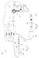
図1から図13は、本発明の実施形態に係るものである。図1は、本発明の実施形態に係る医療用マニピュレータシステムの要部の構成の一例を示す図である。図2は、図1の内視鏡における先端部の先端面の構成の一例を示す図である。図3は、スレーブ側マニピュレータのマニピュレータ腕部を、内視鏡に設けられた処置具チャンネル内に挿通している際の様子を示す図である。図4は、第1のモータ回転量(回転角度)に係る情報を取得する際の、屈曲部の屈曲状態の一例を示す図である。図5は、第2のモータ回転量(回転角度)に係る情報を取得する際の、屈曲部の屈曲状態の一例を示す図である。図6は、スレーブ側マニピュレータのマニピュレータ腕部が処置具突出口から突出された際の様子を示す図である。 1 to 13 relate to an embodiment of the present invention. FIG. 1 is a diagram illustrating an example of a configuration of a main part of a medical manipulator system according to an embodiment of the present invention. FIG. 2 is a diagram illustrating an example of the configuration of the distal end surface of the distal end portion in the endoscope of FIG. FIG. 3 is a diagram illustrating a state in which the manipulator arm portion of the slave-side manipulator is inserted into a treatment instrument channel provided in the endoscope. FIG. 4 is a diagram illustrating an example of a bent state of the bent portion when information related to the first motor rotation amount (rotation angle) is acquired. FIG. 5 is a diagram illustrating an example of a bent state of the bent portion when information related to the second motor rotation amount (rotation angle) is acquired. FIG. 6 is a diagram illustrating a state where the manipulator arm portion of the slave side manipulator is protruded from the treatment instrument protrusion port.
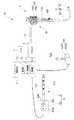
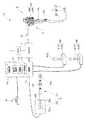
図7は、センサを処置具挿入口の入口付近に設けた場合の一例を示す図である。図8は、図1の医療用マニピュレータシステムにおいて、処置具挿通装置を適用した場合の要部の構成の一例を示す図である。図9は、本発明の実施形態の第1の変形例に係る医療用マニピュレータシステムの要部の構成の一例を示す図である。図10は、本発明の実施形態の第2の変形例に係る医療用マニピュレータシステムの要部の構成の一例を示す図である。図11は、本発明の実施形態の第3の変形例に係る医療用マニピュレータシステムの要部の構成の一例を示す図である。図12は、本発明の実施形態の第4の変形例に係る医療用マニピュレータシステムの要部の構成の一例を示す図である。図13は、本発明の実施形態の第5の変形例に係る医療用マニピュレータシステムの要部の構成の一例を示す図である。 FIG. 7 is a diagram illustrating an example in which a sensor is provided near the entrance of the treatment instrument insertion port. FIG. 8 is a diagram illustrating an example of a configuration of a main part when the treatment instrument insertion device is applied to the medical manipulator system of FIG. 1. FIG. 9 is a diagram illustrating an example of a configuration of a main part of a medical manipulator system according to a first modification of the embodiment of the present invention. FIG. 10 is a diagram illustrating an example of a configuration of a main part of a medical manipulator system according to a second modification of the embodiment of the present invention. FIG. 11 is a diagram illustrating an example of a configuration of a main part of a medical manipulator system according to a third modification of the embodiment of the present invention. FIG. 12 is a diagram illustrating an example of a configuration of a main part of a medical manipulator system according to a fourth modification of the embodiment of the present invention. FIG. 13 is a diagram illustrating an example of a configuration of a main part of a medical manipulator system according to a fifth modification of the embodiment of the present invention.
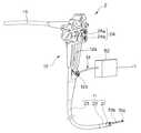
医療用マニピュレータシステム1は、図1に示すように、生体内に挿入される内視鏡2と、プロセッサ3と、モニタ4と、スレーブ側マニピュレータ5と、マスター側マニピュレータ6と、マニピュレータ制御装置7と、を要部として有して構成されている。 As shown in FIG. 1, the
内視鏡2は、生体内へ挿入可能な形状及び寸法を具備する挿入部11と、挿入部11の基端側に連設された内視鏡把持部12aを具備する操作部12と、一端側が操作部12の側面から延設されるとともに、他端側がプロセッサ3に対して着脱自在に接続されるユニバーサルケーブル13と、を有している。 The
挿入部11には、先端側に設けられた先端部21と、先端部21の後部に設けられた湾曲自在な湾曲部22と、湾曲部22の後部に設けられた細長かつ軟性の可撓管部23と、が連設されている。 The
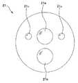
図1等においては省略しているが、先端部21の先端面には、図2に示すように、被写体の像を結像する対物光学系21aと、挿入部11に挿通されている管路としての処置具チャンネルの先端側に連通する処置具突出口21bと、図示しない光源から供給される照明光を出射するための照明光学系21cと、が設けられている。 Although omitted in FIG. 1 and the like, as shown in FIG. 2, an objective
なお、先端部21には、対物光学系21aにより結像された該被写体の像を撮像し、撮像信号として出力する図示しない撮像素子が内蔵されているものとする。また、先端部21は、例えばプラスチック等の比較的硬質な部材により形成されているものとする。 It is assumed that the
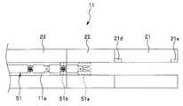
挿入部11の処置具チャンネル11aは、例えば図3に示すように、スレーブ側マニピュレータ5のマニピュレータ腕部51を挿通可能な形状を有している。また、図3に示すように、先端部21の内部には、後述するイニシャライズスイッチ62aがオンしている場合においてマニピュレータ腕部51の各部が通過したことを検知可能な、検知部としてのセンサ21d及びセンサ21eが設けられている。 For example, as shown in FIG. 3, the
操作部12には、湾曲部22の湾曲操作を行う湾曲操作ノブ24aと、湾曲操作ノブ24aを所望の回転位置で固定するための固定レバー24bとを具備する湾曲操作部24等が設けられている。さらに、操作部12には、挿入部11内部の処置具チャンネルの基端側に連通する、処置具挿入口12bが設けられている。 The
プロセッサ3は、ユニバーサルケーブル13を経て出力される撮像信号に対して信号処理を施すことにより、映像信号に変換しつつ出力する。また、プロセッサ3は、内視鏡2とマニピュレータ制御装置7との間における通信を仲介可能な構成を有している。 The
医療用器具としてのスレーブ側マニピュレータ5は、処置具挿入口12bから挿入された後、挿入部11内部の処置具チャンネルを経て処置具突出口21bから突出させることが可能であるような形状を有するマニピュレータ腕部51と、マニピュレータ腕部51の基端側に設けられ、マニピュレータ制御装置7の制御に応じてマニピュレータ腕部51を駆動させるマニピュレータ駆動部52と、を有して構成されている。 The
マニピュレータ腕部51は、挿入部11内部の処置具チャンネルの内部に挿通可能な細長形状を具備するとともに、把持鉗子51aと、屈曲部51bと、を有して構成されている。 The
また、マニピュレータ駆動部52は、回転により駆動力を発生するモータ52aと、モータ52aにおいて生じた駆動力をマニピュレータ腕部51の各部に伝達する一対のワイヤ52bと、を有して構成されている。 The
マニピュレータ腕部51の先端側に設けられた把持鉗子51aは、一対のワイヤ52bにより伝達される駆動力を把持力に変換することにより、対象物を挟んで掴むことが可能な構成を有している。 The grasping
マニピュレータ腕部51の中途に設けられた屈曲部51bは、一対のワイヤ52bにより伝達される駆動力に応じ、図1のD1方向(第1の方向)及びD2方向(第2の方向)に回動可能な図示しない湾曲駒を有して構成されている。 A bending
屈曲用アクチュエータとしてのモータ52aは、マニピュレータ制御装置7の制御に応じて回転することにより、マニピュレータ腕部51の各部を駆動させるための駆動力を発生する。また、モータ52aは、図示しないエンコーダを介し、自身の回転量(回転角度)に関する情報をマニピュレータ制御装置7に対して出力する。 The
マスター側マニピュレータ6は、マニピュレータ腕部51の各部との連動による操作が可能な可動部61と、可動部61の基端側に設けられ、可動部61の操作状態を随時モニタリングしつつマニピュレータ制御装置7へ出力するマスター側制御部62と、を有して構成されている。 The master side manipulator 6 is provided on the base end side of the
可動部61は、可動部61の先端側に設けられ、把持鉗子51aとの連動による操作が可能な鉗子操作部61aと、可動部61の中途に設けられ、屈曲部51bとの連動による操作が可能な屈曲操作部61bと、を有して構成されている。 The
また、マスター側制御部62は、スレーブ側マニピュレータ5の初期化処理を実行させるための指示を行うイニシャライズスイッチ62aを外装表面上に具備している。 Moreover, the master
マニピュレータ制御装置7は、種々の演算処理を行う演算部71と、モータ制御部72と、各種データ及び演算結果等を記憶可能な記憶部73と、を有して構成されている。 The
アクチュエータ制御部としてのモータ制御部72は、マスター側制御部62から随時出力される可動部61の操作状態に基づいてモータ52aを制御することにより、マニピュレータ腕部51の各部を該操作状態に連動させる。 The
ここで、本実施形態の医療用マニピュレータシステム1の作用について説明を行う。 Here, the effect | action of the
まず、術者は、医療用マニピュレータシステム1の各部を起動状態とした後、モニタ4に表示される画像を見ながら、先端部21が所望の処置対象部位に到達するように挿入部11の挿入操作を行う。 First, an operator inserts the
そして、術者は、モニタ4に表示される画像に基づき、先端部21が所望の処置対象部位に到達したことを確認すると、イニシャライズスイッチ62aをオンした後、例えば図3に示すように、マニピュレータ腕部51の把持鉗子51a及び屈曲部51bを挿入部11内部の処置具チャンネル11aに順次挿通してゆく。 Then, when the surgeon confirms that the
一方、イニシャライズスイッチ62aがオンされると、マスター側制御部62は、可動部61を中心軸に沿った直線形状に変形させるとともに、初期化処理中における可動部61への操作を無効にするために、可動部61の各部を一時的に非可動にする(操作できなくする)ための制御を行う。また、イニシャライズスイッチ62aがオンされると、センサ21dにおいて、マニピュレータ腕部51の各部が処置具チャンネル11aにおける先端部21の基端側を通過したか否かの検知が開始される。さらに、イニシャライズスイッチ62aがオンされると、センサ21eにおいて、マニピュレータ腕部51の各部が処置具チャンネル11aにおける先端部21の先端側を通過したか否かの検知が開始される。 On the other hand, when the
センサ21dは、マニピュレータ腕部51の屈曲部51bが処置具チャンネル11aにおける先端部21の基端側を通過したことを検知した際に、検知信号を出力する。 The
センサ21dから出力された検知信号は、内視鏡2の内部に設けられた図示しない信号線、ユニバーサルケーブル13及びプロセッサ3を経てマニピュレータ制御装置7に入力される。 The detection signal output from the
マニピュレータ制御装置7のモータ制御部72は、センサ21dからの検知信号に基づき、スレーブ側マニピュレータ5の初期化処理に必要な情報を得るための制御をマニピュレータ駆動部52に対して行う。 The
具体的には、モータ制御部72は、モータ52aに対する制御により、一対のワイヤ52bにおける弛みがなくなるまで、屈曲部51bの図示しない湾曲駒を図1のD1方向(第1の方向)に回動させる。この場合、屈曲部51bは、例えば図4に示すように、マニピュレータ腕部51の長手方向の中心軸に対して角度αだけ屈曲する。これに伴い、前記角度αに相当するモータ52aの回転量(回転角度)としての第1のモータ回転量(回転角度)に係る情報が、図示しないエンコーダを介して出力された後、マニピュレータ制御装置7の記憶部73に記憶される。 Specifically, the
また、モータ制御部72は、前記第1のモータ回転量(回転角度)に係る情報が記憶部73に記憶されたことを検知すると、モータ52aに対する制御により、一対のワイヤ52bにおける弛みがなくなるまで、屈曲部51bの図示しない湾曲駒を図1のD2方向(第2の方向)に回動させる。この場合、屈曲部51bは、例えば図5に示すように、マニピュレータ腕部51の長手方向の中心軸に対して角度βだけ屈曲する。これに伴い、前記角度βに相当するモータ52aの回転量(回転角度)としての第2のモータ回転量(回転角度)に係る情報が、図示しないエンコーダを介して出力された後、マニピュレータ制御装置7の記憶部73に記憶される。 Further, when the
なお、前述した第1のモータ回転量(回転角度)に係る情報及び第2のモータ回転量(回転角度)に係る情報は、例えば、処置具チャンネル11aから抜去された状態のマニピュレータ腕部51を鉛直に垂らした場合のモータ52aの回転量(回転角度)を0として得られる値であるとする。 For example, the information related to the first motor rotation amount (rotation angle) and the information related to the second motor rotation amount (rotation angle) described above can be obtained from the
一方、マニピュレータ制御装置7の演算部71は、記憶部73に記憶された第1のモータ回転量(回転角度)に係る情報及び第2のモータ回転量(回転角度)に係る情報に基づき、該第1のモータ回転量(回転角度)と該第2のモータ回転量(回転角度)とを加えた値を2で除することにより、湾曲部22の湾曲状態に応じて設定されるモータ52aの回転量としての基準モータ回転量(回転角度)を算出した後、該基準モータ回転量を記憶部73に記憶させる。なお、前記基準モータ回転量は、例えば、一対のワイヤ52bが挿通される図示しない管路に対する、該一対のワイヤ52bの相対的な移動量の値として捉えても良い。 On the other hand, the
また、マニピュレータ制御装置7の演算部71は、記憶部73に記憶された第1のモータ回転量(回転角度)に係る情報及び第2のモータ回転量(回転角度)に係る情報に基づき、該第1のモータ回転量(回転角度)から該第2のモータ回転量(回転角度)を減じた値の絶対値をとることにより、一対のワイヤ52bの弛み状態に応じて設定されるモータ52aの回転量としての補正モータ回転量を算出した後、該補正モータ回転量を記憶部73に記憶させる。 Further, the
モータ制御部72は、記憶部73に記憶された基準モータ回転量及び補正モータ回転量を用いつつ、屈曲部51bが処置具突出口21bから突出される際のモータ52aの回転量を調整するための制御を初期化処理として行う。 The
一例として述べると、モータ制御部72は、屈曲部51bが処置具突出口21bから突出される前に、前述した基準モータ回転量に基づき、屈曲部51bの回動の中心となるモータ52aの回転量(回転角度)の設定を変更し、該屈曲部51bが直線状態となるようにモータ52aを回転させる。換言すると、モータ制御部72は、屈曲した処置具チャンネル11a内に屈曲部51bを挿通した際に生じる、一対のワイヤ52bが挿通される図示しない管路に対する、該一対のワイヤ52bの相対的な移動量を減少する方向にモータ52aを回転させる。 As an example, the
なお、前記初期化処理は、屈曲部51bが処置具チャンネル11aにおける先端部21の先端側を通過したことを示す、センサ21eからの検知信号がモータ制御部72に入力された直後のタイミングにおいて行われるものとする。 The initialization processing is performed at a timing immediately after the detection signal from the
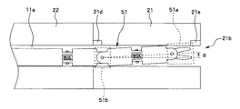
前記初期化処理により、屈曲部51bは、例えば図6に示すように、マニピュレータ腕部51の中心軸に沿った直線形状をとりながら(いずれの方向にも屈曲していない状態として)処置具突出口21bから突出される。すなわち、イニシャライズスイッチ62aがオンされている最中に行われる前記初期化処理により、屈曲部51bが処置具突出口21bから突出される際のマニピュレータ腕部51の屈曲状態と可動部61の屈曲状態との整合がとられる。 By the initialization process, the bending
なお、本実施形態においては、センサ21dを先端部21の基端側に具備し、かつ、センサ21eを先端部の先端側に具備したものに限らず、例えば図7に示すように、先端部21と略同様の比較的硬質な部材により形成された処置具挿入口12bの入口付近にセンサ21dを具備し、かつ、処置具挿入口12bと処置具チャンネル11aとが合流する箇所の付近にセンサ21eを具備するものであっても良い。 In the present embodiment, the
また、医療用マニピュレータシステム1においては、モータ52aと屈曲部51bとが一対のワイヤ52bを介して接続されるものに限らず、例えば、サーボモータとして構成されたモータ52aが屈曲部51bに組み込まれるものであっても良い。 Further, in the
この場合、演算部71は、センサ21dからの検知信号が入力された略直後におけるモータ52aの回転量を検知し、該回転量に基づき、屈曲部51bを直線形状にするために必要なモータ52aの回転量の演算を行う。そして、センサ21eからの検知信号が入力された略直後において、モータ制御部72が前記回転量に基づく初期化処理をモータ52aに対して行うことにより、屈曲部51bが処置具突出口21bから突出される際のマニピュレータ腕部51の屈曲状態と可動部61の屈曲状態との整合がとられる。 In this case, the
以上に述べたように、本実施形態の医療用マニピュレータシステム1は、マニピュレータ腕部51を処置具チャンネル11aに挿通する間に、スレーブ側マニピュレータ5とマスター側マニピュレータ6とにおける屈曲状態の整合をとるための初期化処理を行うことが可能な構成及び作用を有している。そのため、本実施形態の医療用マニピュレータシステム1は、所望の部位に対する処置に費やされる時間を従来に比べて短縮することができる。 As described above, the
なお、本実施形態の医療用マニピュレータシステム1は、スレーブ側マニピュレータ5の挿通状態をセンサ21d及びセンサ21eにより検知するものに限らず、例えば図8に示すように、該挿通状態を処置具挿通装置12cにより検知可能な、医療用マニピュレータシステム101として構成されるものであっても良い。 The
医療用マニピュレータシステム101は、医療用マニピュレータシステム1における処置具挿入口12bの近傍に処置具挿通装置12cを取り付け、かつ、医療用マニピュレータシステム1におけるセンサ21d及びセンサ21e(図8には図示せず)を取り除いたものと略同様の構成を具備している。 The
挿入用アクチュエータとしての機能を有する処置具挿通装置12cは、モータ制御部72の制御に基づいて動作し、処置具挿入口12bから挿入されたスレーブ側マニピュレータ5を処置具チャンネル11aの内部に挿通する際の駆動力を供給可能な、図示しないモータ及び駆動用ローラ等を内部に有している。また、処置具挿通装置12cは、スレーブ側マニピュレータ5の処置具チャンネル11aの内部における挿通量を前記図示しないモータの回転量に基づいて検知し、検知結果としての該挿通量の情報をマニピュレータ制御装置7へ随時出力する。 The treatment
ここで、医療用マニピュレータシステム101の作用について説明を行う。なお、説明の簡単のため、既述の内容と同様の部分については、適宜省略しつつ以降の説明を行うものとする。 Here, the operation of the
イニシャライズスイッチ62aがオンされると、演算部71は、処置具挿通装置12cから出力される挿通量の情報に基づき、該挿通量の監視を開始する。そして、演算部71は、前記挿通量が所定の量(例えば先端部21に到達可能な量)になったことを検知すると、検知結果をモータ制御部72へ出力する。 When the
そして、モータ制御部72が前述した制御を行うことにより、第1のモータ回転量及び第2のモータ回転量が記憶部73に記憶される。 Then, when the
一方、演算部71は、第1のモータ回転量及び第2のモータ回転量に基づいて基準モータ回転量及び補正モータ回転量を算出した後、該基準モータ回転量及び該補正モータ回転量を記憶部73に記憶させる。なお、基準モータ回転量及び補正モータ回転量を算出するための演算方法は、前述したものと同様である。 On the other hand, the
モータ制御部72は、記憶部73に記憶された基準モータ回転量及び補正モータ回転量を用いつつ、屈曲部51bが処置具突出口21bから突出される際のモータ52aの回転量を調整するための制御を初期化処理として行う。 The
なお、医療用マニピュレータシステム101における初期化処理は、イニシャライズスイッチ62aがオンされた後、スレーブ側マニピュレータ5の挿入量が所定の量になったことを演算部71が検知した略直後のタイミングにおいて行われるものとする。 The initialization process in the
また、医療用マニピュレータシステム101においては、モータ52aと屈曲部51bとが一対のワイヤ52bを介して接続されるものに限らず、例えば、サーボモータとして構成されたモータ52aが屈曲部51bに組み込まれるものであっても良い。 Further, in the
この場合、演算部71は、スレーブ側マニピュレータ5の挿通量が所定の量になった略直後におけるモータ52aの回転量を検知し、該回転量に基づき、屈曲部51bを直線形状にするために必要なモータ52aの回転量の演算を行う。その後、モータ制御部72が前記回転量に基づく初期化処理をモータ52aに対して行うことにより、屈曲部51bが処置具突出口21bから突出される際のマニピュレータ腕部51の屈曲状態と可動部61の屈曲状態との整合がとられる。 In this case, the
そして、以上に述べた医療用マニピュレータシステム101の構成及び作用によれば、(センサ21d及びセンサ21eによらずとも、)スレーブ側マニピュレータ5の挿通状態(挿通量)を処置具挿通装置12cから取得できる。そのため、医療用マニピュレータシステム101は、前述した、医療用マニピュレータシステム1と同様の効果を得ることができる。 Then, according to the configuration and operation of the
ここで、本実施形態において適用可能な種々の変形例について説明を行う。なお、以降において、医療用マニピュレータシステム1の構成または作用として既述である部分については適宜省略しつつ説明を行う。 Here, various modifications applicable in the present embodiment will be described. In the following, description will be made while appropriately omitting portions already described as the configuration or operation of the
本実施形態の医療用マニピュレータシステム1は、屈曲部51bが1箇所にのみ設けられたスレーブ側マニピュレータ5を有して構成されるものに限らず、例えば図9に示すように、屈曲部51bが複数箇所に設けられたスレーブ側マニピュレータ5Aを有する医療用マニピュレータシステム1Aとして構成されるものであっても良い。 The
具体的には、本実施形態の第1の変形例としての医療用マニピュレータシステム1Aは、内視鏡2と、プロセッサ3と、モニタ4と、スレーブ側マニピュレータ5Aと、マスター側マニピュレータ6Aと、マニピュレータ制御装置7と、を要部として有して構成されている。 Specifically, a
スレーブ側マニピュレータ5Aは、マニピュレータ腕部51A及びマニピュレータ駆動部52を有して構成されているとともに、マニピュレータ腕部51Aの中途の複数箇所に屈曲部51bが設けられている。(なお、図9においては、各屈曲部51bのうち、マニピュレータ腕部51Aにおいて最も先端側に設けられているもの、及び、マニピュレータ腕部51Aにおいて最も基端側に設けられているものの2つのみを示してある。)
また、マスター側マニピュレータ6Aは、可動部61A及びマスター側制御部62を有して構成されているとともに、可動部61Aの中途の複数箇所に屈曲操作部61bが設けられている。(なお、図9においては、各屈曲操作部61bのうち、可動部61Aにおいて最も先端側に設けられているもの、及び、可動部61Aにおいて最も基端側に設けられているものの2つのみを示してある。)
そして、医療用マニピュレータシステム1Aにおいては、屈曲部51bが1つである場合の初期化処理と同様の処理が、各屈曲部51bについて順次行われる。The
Further, the master side manipulator 6A includes a
In the
具体的には、一の屈曲部51bが処置具チャンネル11aにおける先端部21を通過する毎に、該一の屈曲部51bに対応する第1のモータ回転量(回転角度)に係る情報及び第2のモータ回転量(回転角度)に係る情報が取得され、該一の屈曲部51bに対応する基準モータ回転量及び補正モータ回転量が算出され、該一の屈曲部51bが処置具突出口21bから突出する際のモータ52aの回転量が調整される。これにより、複数箇所に屈曲部51bが設けられているマニピュレータ腕部51Aであっても、各屈曲部51bがマニピュレータ腕部51Aの中心軸に沿った直線形状をとりながら(いずれの方向にも屈曲していない状態として)処置具突出口21bから突出される。 Specifically, each time one
なお、医療用マニピュレータシステム1Aにおける、前述した部分以外の動作等は、医療用マニピュレータシステム1と略同様である。 The operations other than those described above in the
本実施形態の医療用マニピュレータシステム1は、スレーブ側マニピュレータ5をマスター側マニピュレータ6により操作可能な構成を有するものに限らず、例えば図10に示すように、スレーブ側マニピュレータ5をジョイスティック6Bにより操作可能な医療用マニピュレータシステム1Bとして構成されるものであっても良い。 The
具体的には、本実施形態の第2の変形例としての医療用マニピュレータシステム1Bは、内視鏡2と、プロセッサ3と、モニタ4と、スレーブ側マニピュレータ5と、ジョイスティック6Bと、マニピュレータ制御装置7と、を要部として有して構成されている。 Specifically, a
ジョイスティック6Bは、イニシャライズスイッチ62aが設けられたレバー61Bと、レバー61Bを支持可能な形状であるとともに、信号線を介してマニピュレータ制御装置7に接続される台座部62Bと、を有して構成されている。 The
医療用マニピュレータシステム1Bにおけるモータ制御部72は、レバー61Bの傾斜状態に応じた操作指示に基づいてモータ52aを制御することにより、マニピュレータ腕部51の各部を該操作指示に連動させる。 The
そして、医療用マニピュレータシステム1Bにおいては、初期化処理として、マニピュレータ腕部51の屈曲状態とレバー61Bの傾斜状態とを整合させるための処理が行われる。 In the
具体的には、イニシャライズスイッチ62aがオンされた際にレバー61Bが一時的にニュートラル位置にロックされ、該ニュートラル位置における第1のモータ回転量(回転角度)に係る情報及び第2のモータ回転量(回転角度)に係る情報が取得され、該ニュートラル位置における基準モータ回転量及び補正モータ回転量が算出され、屈曲部51bが処置具突出口21bから突出する際のモータ52aの回転量が調整される。これにより、レバー61Bのニュートラル位置に相当する屈曲部51bの形状が、マニピュレータ腕部51Aの中心軸に沿った直線形状となるように整合がとられる。 Specifically, when the
なお、医療用マニピュレータシステム1Bにおける、前述した部分以外の動作等は、医療用マニピュレータシステム1と略同様である。 In addition, operations other than the above-described portions in the
医療用マニピュレータシステム1Bは、スレーブ側マニピュレータ5を操作するジョイスティック6Bを複数のジョイスティック6Bの中から1つ選択することができるような、例えば図11に示す医療用マニピュレータシステム1Cとして構成されるものであっても良い。 The
具体的には、本実施形態の第3の変形例としての医療用マニピュレータシステム1Cは、内視鏡2と、プロセッサ3と、モニタ4と、スレーブ側マニピュレータ5と、複数のジョイスティック6Bと、マニピュレータ制御装置7Aと、スレーブ側マニピュレータ5を操作するジョイスティック6Bを複数のジョイスティック6Bの中から1つ選択可能な選択スイッチ8と、を要部として有して構成されている。(なお、図11においては、図示の簡単のため、医療用マニピュレータシステム1Cがジョイスティック6Bを2つ有するものとして示してある。また、選択スイッチ8の形状等は、図11に示した以外のものであっても構わない。)
マニピュレータ制御装置7Aは、演算部71と、モータ制御部72と、記憶部73と、選択スイッチ8によって選択されたジョイスティック6Bからの操作指示のみがモータ制御部72に入力されるように切替動作を行う操作系切替部74と、を有して構成されている。Specifically, a
The
なお、医療用マニピュレータシステム1Cにおける主要部の動作等は、医療用マニピュレータシステム1Bと略同様である。 The operation of the main part in the
医療用マニピュレータシステム1Bは、把持鉗子51aが先端側に設けられたスレーブ側マニピュレータ5を有して構成されるものに限らず、例えば図12に示すように、高周波電流を出力可能なアクティブ電極51cが先端側に設けられたスレーブ側マニピュレータ5Bを有する医療用マニピュレータシステム1Dとして構成されるものであっても良い。 The
具体的には、本実施形態の第4の変形例としての医療用マニピュレータシステム1Dは、内視鏡2と、プロセッサ3と、モニタ4と、所望の処置部位に対して高周波電流を出力可能なスレーブ側マニピュレータ5Bと、ジョイスティック6Bと、スレーブ側マニピュレータ5Bへ高周波電流を供給するマニピュレータ制御装置7Bと、該所望の処置部位を経た高周波電流を回収するためのリターン電極9と、を要部として有して構成されている。 Specifically, the medical manipulator system 1D as the fourth modification of the present embodiment can output a high-frequency current to the
スレーブ側マニピュレータ5Bは、屈曲部51b、及び、マニピュレータ制御装置7Bから供給された高周波電流を所望の処置部位に対して出力するアクティブ電極51cを具備するマニピュレータ腕部51Bと、マニピュレータ駆動部52と、を有して構成されている。 The
マニピュレータ制御装置7Bは、演算部71と、モータ制御部72と、記憶部73と、スレーブ側マニピュレータ5Bへ高周波電流を供給するとともに、リターン電極9において回収された高周波電流が入力される高周波電源部75と、を有して構成されている。 The manipulator control device 7B supplies a high-frequency current to the
医療用マニピュレータシステム1Dにおけるモータ制御部72は、レバー61Bの傾斜状態に応じた操作指示に基づいてモータ52aを制御することにより、マニピュレータ腕部51Bの各部を該操作指示に連動させる。 The
なお、医療用マニピュレータシステム1Dにおける主要部の動作等は、医療用マニピュレータシステム1Bと略同様である。 The operation of the main part in the medical manipulator system 1D is substantially the same as that of the
医療用マニピュレータシステム1Cは、2つのスレーブ側マニピュレータ5及び5Bを同時に使用することができるような、例えば図13に示す医療用マニピュレータシステム1Eとして構成されるものであっても良い。 The
具体的には、本実施形態の第5の変形例としての医療用マニピュレータシステム1Eは、内視鏡2と、プロセッサ3と、モニタ4と、スレーブ側マニピュレータ5及び5Bと、複数のジョイスティック6Bと、マニピュレータ制御装置7Cと、スレーブ側マニピュレータ5及び5Bを操作するジョイスティック6Bを複数のジョイスティック6Bの中から1つずつ選択可能な選択スイッチ8Aと、リターン電極9と、を要部として有して構成されている。(なお、選択スイッチ8Aの形状等は、図13に示した以外のものであっても構わない。)
マニピュレータ制御装置7Cは、演算部71と、モータ制御部72と、記憶部73と、操作系切替部74と、高周波電源部75と、を有して構成されている。Specifically, a
The
なお、医療用マニピュレータシステム1Eにおける主要部の動作等は、医療用マニピュレータシステム1Cと略同様である。 The operation of the main part in the
本実施形態においては、以上に述べた各変形例を(単独でまたは適宜組み合わせて)適用した場合においても、前述した、医療用マニピュレータシステム1の効果と同様の効果を得ることができる。また、以上に述べた各変形例は、医療用マニピュレータシステム101の構成においても適宜用いることができる。 In the present embodiment, even when each of the above-described modified examples (alone or in appropriate combination) is applied, the same effects as those of the
なお、本実施形態及び変形例として前述した各医療用マニピュレータシステムにおいては、例えば、ネットワーク回線または無線通信等を介し、遠隔地からスレーブ側マニピュレータを操作可能な構成が付加されるものであっても良い。 In addition, in each medical manipulator system described above as the present embodiment and the modification, for example, a configuration in which the slave side manipulator can be operated from a remote place via a network line or wireless communication is added. good.
また、本実施形態における初期化処理は、内視鏡の処置具チャンネルの内部にスレーブ側マニピュレータを挿通している最中に行われるものに限らず、例えば、センサ21d及び21eを有する管路としてのトラカールの内部にスレーブ側マニピュレータ5を挿通している最中に行われるものであっても良い。 In addition, the initialization process in the present embodiment is not limited to the process performed while the slave side manipulator is inserted into the treatment instrument channel of the endoscope. For example, the initialization process is performed as a conduit having the
本発明は、上述した各実施形態に限定されるものではなく、発明の趣旨を逸脱しない範囲内において種々の変更や応用が可能であることは勿論である。 The present invention is not limited to the above-described embodiments, and various changes and applications can be made without departing from the spirit of the invention.
1,101 医療用マニピュレータシステム
2 内視鏡
3 プロセッサ
4 モニタ
5 スレーブ側マニピュレータ
6 マスター側マニピュレータ
7 マニピュレータ制御装置
11 挿入部
11a 処置具チャンネル
12b 処置具挿入口
12c 処置具挿通装置
21b 処置具突出口
21d センサ
21e センサ
51 マニピュレータ腕部
52 マニピュレータ駆動部
61 可動部
62 マスター側制御部
62a イニシャライズスイッチ
71 演算部
72 モータ制御部
73 記憶部DESCRIPTION OF SYMBOLS 1,101
Claims (5)
Translated fromJapanese前記屈曲部を屈曲させるための駆動力を供給する屈曲用アクチュエータと、
前記屈曲用アクチュエータを制御するためのアクチュエータ制御部と、
前記管路の内部に設けられ、前記屈曲部が通過したことを検知した際に検知信号を出力する検知部と、
前記検知信号が入力された際に、前記屈曲用アクチュエータの動作量を検知するとともに、該動作量に基づき、前記検知部を通過した前記屈曲部の屈曲状態と前記屈曲部を屈曲させるための操作が可能な操作部の操作状態とを整合させるための演算を行う演算部と、
を有することを特徴とする医療用マニピュレータシステム。A medical instrument having a shape that can be inserted into an elongated duct, and having one or a plurality of bent portions;
A bending actuator for supplying a driving force for bending the bent portion;
An actuator controller for controlling the bending actuator;
A detection unit that is provided inside the pipe and outputs a detection signal when it is detected that the bent portion has passed;
When the detection signal is input, the operation amount of the bending actuator is detected, and the bending state of the bending portion that has passed through the detection portion and the operation for bending the bending portion are based on the operation amount. A calculation unit that performs a calculation to match the operation state of the operation unit capable of
A medical manipulator system comprising:
前記屈曲部を屈曲させるための駆動力を供給する屈曲用アクチュエータと、
前記医療用器具を前記管路の内部に挿通する際の駆動力を供給する挿入用アクチュエータと、
前記屈曲用アクチュエータ及び前記挿入用アクチュエータを制御するためのアクチュエータ制御部と、
前記挿入用アクチュエータにより前記医療用器具が前記管路に所定の量挿通された際に、前記屈曲用アクチュエータの動作量を検知するとともに、該動作量に基づき、前記検知部を通過した前記屈曲部の屈曲状態と前記屈曲部を屈曲させるための操作が可能な操作部の操作状態とを整合させるための演算を行う演算部と、
を有することを特徴とする医療用マニピュレータシステム。A medical instrument having a shape that can be inserted into an elongated duct, and having one or a plurality of bent portions;
A bending actuator for supplying a driving force for bending the bent portion;
An insertion actuator for supplying a driving force when the medical instrument is inserted into the duct;
An actuator controller for controlling the bending actuator and the insertion actuator;
When the medical instrument is inserted through the duct by a predetermined amount by the insertion actuator, the bending portion that detects the operation amount of the bending actuator and passes the detection unit based on the operation amount. A calculation unit that performs a calculation for matching the bending state of the operation unit and the operation state of the operation unit that can be operated to bend the bending portion;
A medical manipulator system comprising:
ワイヤにより前記屈曲部と接続され、該ワイヤを介して前記屈曲部を屈曲させるための駆動力を供給する屈曲用アクチュエータと、
前記管路の内部に設けられ、前記屈曲部が通過したことを検知した際に検知信号を出力する検知部と、
前記検知信号が入力された際に、前記ワイヤの弛みがなくなるまで前記屈曲用アクチュエータを駆動させる制御を行うアクチュエータ制御部と、
前記アクチュエータ制御部の制御に伴う前記屈曲用アクチュエータの駆動量を検知するとともに、該駆動量に基づき、前記検知部を通過した前記屈曲部の屈曲状態と前記屈曲部を屈曲させるための操作が可能な操作部の操作状態とを整合させるための演算を行う演算部と、
を有することを特徴とする医療用マニピュレータシステム。A medical instrument having a shape that can be inserted into an elongated duct, and having one or a plurality of bent portions;
A bending actuator connected to the bent portion by a wire and supplying a driving force for bending the bent portion through the wire;
A detection unit that is provided inside the pipe and outputs a detection signal when it is detected that the bent portion has passed;
An actuator control unit that performs control to drive the bending actuator until the wire is loosened when the detection signal is input;
The driving amount of the bending actuator accompanying the control of the actuator control unit is detected, and the bending state of the bending portion that has passed through the detection unit and the operation for bending the bending portion can be performed based on the driving amount. A calculation unit that performs a calculation for matching the operation state of the various operation units,
A medical manipulator system comprising:
前記医療用器具を前記管路の内部に挿通する際の駆動力を供給する挿入用アクチュエータと、
ワイヤにより前記屈曲部と接続され、該ワイヤを介して前記屈曲部を屈曲させるための駆動力を供給する屈曲用アクチュエータと、
前記挿入用アクチュエータを制御するとともに、前記挿入用アクチュエータにより前記医療用器具が前記管路に所定の量挿通された際に、前記ワイヤの弛みがなくなるまで前記屈曲用アクチュエータを駆動させる制御を行うアクチュエータ制御部と、
前記挿入用アクチュエータにより前記医療用器具が前記管路に前記所定の量挿通された際に、前記アクチュエータ制御部の制御に伴う前記屈曲用アクチュエータの動作量を検知するとともに、該動作量に基づき、前記検知部を通過した前記屈曲部の屈曲状態と前記屈曲部を屈曲させるための操作が可能な操作部の操作状態とを整合させるための演算を行う演算部と、
を有することを特徴とする医療用マニピュレータシステム。A medical instrument having a shape that can be inserted into an elongated duct, and having one or a plurality of bent portions;
An insertion actuator for supplying a driving force when the medical instrument is inserted into the duct;
A bending actuator connected to the bent portion by a wire and supplying a driving force for bending the bent portion through the wire;
An actuator that controls the insertion actuator and drives the bending actuator until the wire is loosened when the medical instrument is inserted through the conduit by the insertion actuator. A control unit;
When the medical instrument is inserted into the conduit by the insertion actuator by the predetermined amount, the operation amount of the bending actuator accompanying the control of the actuator control unit is detected, and based on the operation amount, A calculation unit that performs a calculation for matching the bending state of the bending portion that has passed through the detection unit and the operation state of the operation unit that is operable to bend the bending portion;
A medical manipulator system comprising:
Priority Applications (4)
| Application Number | Priority Date | Filing Date | Title |
|---|---|---|---|
| JP2008099550AJP5301867B2 (en) | 2008-04-07 | 2008-04-07 | Medical manipulator system |
| CN2009101340211ACN101554335B (en) | 2008-04-07 | 2009-04-03 | Medical manipulator system |
| US12/418,770US20090253959A1 (en) | 2008-04-07 | 2009-04-06 | Medical manipulator system |
| EP09005099.8AEP2108329A3 (en) | 2008-04-07 | 2009-04-07 | Medical manipulator system |
Applications Claiming Priority (1)
| Application Number | Priority Date | Filing Date | Title |
|---|---|---|---|
| JP2008099550AJP5301867B2 (en) | 2008-04-07 | 2008-04-07 | Medical manipulator system |
Publications (2)
| Publication Number | Publication Date |
|---|---|
| JP2009247619A JP2009247619A (en) | 2009-10-29 |
| JP5301867B2true JP5301867B2 (en) | 2013-09-25 |
Family
ID=40758460
Family Applications (1)
| Application Number | Title | Priority Date | Filing Date |
|---|---|---|---|
| JP2008099550AActiveJP5301867B2 (en) | 2008-04-07 | 2008-04-07 | Medical manipulator system |
Country Status (4)
| Country | Link |
|---|---|
| US (1) | US20090253959A1 (en) |
| EP (1) | EP2108329A3 (en) |
| JP (1) | JP5301867B2 (en) |
| CN (1) | CN101554335B (en) |
Families Citing this family (469)
| Publication number | Priority date | Publication date | Assignee | Title |
|---|---|---|---|---|
| US20070084897A1 (en) | 2003-05-20 | 2007-04-19 | Shelton Frederick E Iv | Articulating surgical stapling instrument incorporating a two-piece e-beam firing mechanism |
| US9060770B2 (en) | 2003-05-20 | 2015-06-23 | Ethicon Endo-Surgery, Inc. | Robotically-driven surgical instrument with E-beam driver |
| US11890012B2 (en) | 2004-07-28 | 2024-02-06 | Cilag Gmbh International | Staple cartridge comprising cartridge body and attached support |
| US9072535B2 (en) | 2011-05-27 | 2015-07-07 | Ethicon Endo-Surgery, Inc. | Surgical stapling instruments with rotatable staple deployment arrangements |
| US8215531B2 (en) | 2004-07-28 | 2012-07-10 | Ethicon Endo-Surgery, Inc. | Surgical stapling instrument having a medical substance dispenser |
| US11998198B2 (en) | 2004-07-28 | 2024-06-04 | Cilag Gmbh International | Surgical stapling instrument incorporating a two-piece E-beam firing mechanism |
| US7934630B2 (en) | 2005-08-31 | 2011-05-03 | Ethicon Endo-Surgery, Inc. | Staple cartridges for forming staples having differing formed staple heights |
| US9237891B2 (en) | 2005-08-31 | 2016-01-19 | Ethicon Endo-Surgery, Inc. | Robotically-controlled surgical stapling devices that produce formed staples having different lengths |
| US11246590B2 (en) | 2005-08-31 | 2022-02-15 | Cilag Gmbh International | Staple cartridge including staple drivers having different unfired heights |
| US10159482B2 (en) | 2005-08-31 | 2018-12-25 | Ethicon Llc | Fastener cartridge assembly comprising a fixed anvil and different staple heights |
| US11484312B2 (en) | 2005-08-31 | 2022-11-01 | Cilag Gmbh International | Staple cartridge comprising a staple driver arrangement |
| US7673781B2 (en) | 2005-08-31 | 2010-03-09 | Ethicon Endo-Surgery, Inc. | Surgical stapling device with staple driver that supports multiple wire diameter staples |
| US7669746B2 (en) | 2005-08-31 | 2010-03-02 | Ethicon Endo-Surgery, Inc. | Staple cartridges for forming staples having differing formed staple heights |
| US20070106317A1 (en) | 2005-11-09 | 2007-05-10 | Shelton Frederick E Iv | Hydraulically and electrically actuated articulation joints for surgical instruments |
| US7845537B2 (en) | 2006-01-31 | 2010-12-07 | Ethicon Endo-Surgery, Inc. | Surgical instrument having recording capabilities |
| US20120292367A1 (en) | 2006-01-31 | 2012-11-22 | Ethicon Endo-Surgery, Inc. | Robotically-controlled end effector |
| US11224427B2 (en) | 2006-01-31 | 2022-01-18 | Cilag Gmbh International | Surgical stapling system including a console and retraction assembly |
| US11278279B2 (en) | 2006-01-31 | 2022-03-22 | Cilag Gmbh International | Surgical instrument assembly |
| US20110024477A1 (en) | 2009-02-06 | 2011-02-03 | Hall Steven G | Driven Surgical Stapler Improvements |
| US8708213B2 (en) | 2006-01-31 | 2014-04-29 | Ethicon Endo-Surgery, Inc. | Surgical instrument having a feedback system |
| US20110295295A1 (en) | 2006-01-31 | 2011-12-01 | Ethicon Endo-Surgery, Inc. | Robotically-controlled surgical instrument having recording capabilities |
| US9861359B2 (en) | 2006-01-31 | 2018-01-09 | Ethicon Llc | Powered surgical instruments with firing system lockout arrangements |
| US8820603B2 (en) | 2006-01-31 | 2014-09-02 | Ethicon Endo-Surgery, Inc. | Accessing data stored in a memory of a surgical instrument |
| US8186555B2 (en) | 2006-01-31 | 2012-05-29 | Ethicon Endo-Surgery, Inc. | Motor-driven surgical cutting and fastening instrument with mechanical closure system |
| US11793518B2 (en) | 2006-01-31 | 2023-10-24 | Cilag Gmbh International | Powered surgical instruments with firing system lockout arrangements |
| US7753904B2 (en) | 2006-01-31 | 2010-07-13 | Ethicon Endo-Surgery, Inc. | Endoscopic surgical instrument with a handle that can articulate with respect to the shaft |
| US8992422B2 (en) | 2006-03-23 | 2015-03-31 | Ethicon Endo-Surgery, Inc. | Robotically-controlled endoscopic accessory channel |
| US8236010B2 (en) | 2006-03-23 | 2012-08-07 | Ethicon Endo-Surgery, Inc. | Surgical fastener and cutter with mimicking end effector |
| US8322455B2 (en) | 2006-06-27 | 2012-12-04 | Ethicon Endo-Surgery, Inc. | Manually driven surgical cutting and fastening instrument |
| US7506791B2 (en) | 2006-09-29 | 2009-03-24 | Ethicon Endo-Surgery, Inc. | Surgical stapling instrument with mechanical mechanism for limiting maximum tissue compression |
| US10568652B2 (en) | 2006-09-29 | 2020-02-25 | Ethicon Llc | Surgical staples having attached drivers of different heights and stapling instruments for deploying the same |
| US11980366B2 (en) | 2006-10-03 | 2024-05-14 | Cilag Gmbh International | Surgical instrument |
| US8684253B2 (en) | 2007-01-10 | 2014-04-01 | Ethicon Endo-Surgery, Inc. | Surgical instrument with wireless communication between a control unit of a robotic system and remote sensor |
| US11291441B2 (en) | 2007-01-10 | 2022-04-05 | Cilag Gmbh International | Surgical instrument with wireless communication between control unit and remote sensor |
| US8632535B2 (en) | 2007-01-10 | 2014-01-21 | Ethicon Endo-Surgery, Inc. | Interlock and surgical instrument including same |
| US8652120B2 (en) | 2007-01-10 | 2014-02-18 | Ethicon Endo-Surgery, Inc. | Surgical instrument with wireless communication between control unit and sensor transponders |
| US20080169333A1 (en) | 2007-01-11 | 2008-07-17 | Shelton Frederick E | Surgical stapler end effector with tapered distal end |
| US11039836B2 (en) | 2007-01-11 | 2021-06-22 | Cilag Gmbh International | Staple cartridge for use with a surgical stapling instrument |
| US7673782B2 (en) | 2007-03-15 | 2010-03-09 | Ethicon Endo-Surgery, Inc. | Surgical stapling instrument having a releasable buttress material |
| US8893946B2 (en) | 2007-03-28 | 2014-11-25 | Ethicon Endo-Surgery, Inc. | Laparoscopic tissue thickness and clamp load measuring devices |
| US11564682B2 (en) | 2007-06-04 | 2023-01-31 | Cilag Gmbh International | Surgical stapler device |
| US8931682B2 (en) | 2007-06-04 | 2015-01-13 | Ethicon Endo-Surgery, Inc. | Robotically-controlled shaft based rotary drive systems for surgical instruments |
| US8408439B2 (en) | 2007-06-22 | 2013-04-02 | Ethicon Endo-Surgery, Inc. | Surgical stapling instrument with an articulatable end effector |
| US7753245B2 (en) | 2007-06-22 | 2010-07-13 | Ethicon Endo-Surgery, Inc. | Surgical stapling instruments |
| US11849941B2 (en) | 2007-06-29 | 2023-12-26 | Cilag Gmbh International | Staple cartridge having staple cavities extending at a transverse angle relative to a longitudinal cartridge axis |
| US8758391B2 (en) | 2008-02-14 | 2014-06-24 | Ethicon Endo-Surgery, Inc. | Interchangeable tools for surgical instruments |
| JP5410110B2 (en) | 2008-02-14 | 2014-02-05 | エシコン・エンド−サージェリィ・インコーポレイテッド | Surgical cutting / fixing instrument with RF electrode |
| US8657174B2 (en) | 2008-02-14 | 2014-02-25 | Ethicon Endo-Surgery, Inc. | Motorized surgical cutting and fastening instrument having handle based power source |
| US7819298B2 (en) | 2008-02-14 | 2010-10-26 | Ethicon Endo-Surgery, Inc. | Surgical stapling apparatus with control features operable with one hand |
| US11986183B2 (en) | 2008-02-14 | 2024-05-21 | Cilag Gmbh International | Surgical cutting and fastening instrument comprising a plurality of sensors to measure an electrical parameter |
| US8636736B2 (en) | 2008-02-14 | 2014-01-28 | Ethicon Endo-Surgery, Inc. | Motorized surgical cutting and fastening instrument |
| US9179912B2 (en) | 2008-02-14 | 2015-11-10 | Ethicon Endo-Surgery, Inc. | Robotically-controlled motorized surgical cutting and fastening instrument |
| US7866527B2 (en) | 2008-02-14 | 2011-01-11 | Ethicon Endo-Surgery, Inc. | Surgical stapling apparatus with interlockable firing system |
| US8573465B2 (en) | 2008-02-14 | 2013-11-05 | Ethicon Endo-Surgery, Inc. | Robotically-controlled surgical end effector system with rotary actuated closure systems |
| US11272927B2 (en) | 2008-02-15 | 2022-03-15 | Cilag Gmbh International | Layer arrangements for surgical staple cartridges |
| US9585657B2 (en) | 2008-02-15 | 2017-03-07 | Ethicon Endo-Surgery, Llc | Actuator for releasing a layer of material from a surgical end effector |
| US9386983B2 (en) | 2008-09-23 | 2016-07-12 | Ethicon Endo-Surgery, Llc | Robotically-controlled motorized surgical instrument |
| US8210411B2 (en) | 2008-09-23 | 2012-07-03 | Ethicon Endo-Surgery, Inc. | Motor-driven surgical cutting instrument |
| US9005230B2 (en) | 2008-09-23 | 2015-04-14 | Ethicon Endo-Surgery, Inc. | Motorized surgical instrument |
| US11648005B2 (en) | 2008-09-23 | 2023-05-16 | Cilag Gmbh International | Robotically-controlled motorized surgical instrument with an end effector |
| US8608045B2 (en) | 2008-10-10 | 2013-12-17 | Ethicon Endo-Sugery, Inc. | Powered surgical cutting and stapling apparatus with manually retractable firing system |
| US8517239B2 (en) | 2009-02-05 | 2013-08-27 | Ethicon Endo-Surgery, Inc. | Surgical stapling instrument comprising a magnetic element driver |
| RU2525225C2 (en) | 2009-02-06 | 2014-08-10 | Этикон Эндо-Серджери, Инк. | Improvement of drive surgical suturing instrument |
| US8444036B2 (en) | 2009-02-06 | 2013-05-21 | Ethicon Endo-Surgery, Inc. | Motor driven surgical fastener device with mechanisms for adjusting a tissue gap within the end effector |
| US8851354B2 (en) | 2009-12-24 | 2014-10-07 | Ethicon Endo-Surgery, Inc. | Surgical cutting instrument that analyzes tissue thickness |
| US8220688B2 (en) | 2009-12-24 | 2012-07-17 | Ethicon Endo-Surgery, Inc. | Motor-driven surgical cutting instrument with electric actuator directional control assembly |
| CN102573599B (en) | 2010-03-02 | 2015-05-06 | 奥林巴斯医疗株式会社 | Medical system and control method |
| US8783543B2 (en) | 2010-07-30 | 2014-07-22 | Ethicon Endo-Surgery, Inc. | Tissue acquisition arrangements and methods for surgical stapling devices |
| US9220501B2 (en) | 2010-09-30 | 2015-12-29 | Ethicon Endo-Surgery, Inc. | Tissue thickness compensators |
| US9055941B2 (en) | 2011-09-23 | 2015-06-16 | Ethicon Endo-Surgery, Inc. | Staple cartridge including collapsible deck |
| US12213666B2 (en) | 2010-09-30 | 2025-02-04 | Cilag Gmbh International | Tissue thickness compensator comprising layers |
| US9629814B2 (en) | 2010-09-30 | 2017-04-25 | Ethicon Endo-Surgery, Llc | Tissue thickness compensator configured to redistribute compressive forces |
| US9301753B2 (en) | 2010-09-30 | 2016-04-05 | Ethicon Endo-Surgery, Llc | Expandable tissue thickness compensator |
| US9277919B2 (en) | 2010-09-30 | 2016-03-08 | Ethicon Endo-Surgery, Llc | Tissue thickness compensator comprising fibers to produce a resilient load |
| US9351730B2 (en) | 2011-04-29 | 2016-05-31 | Ethicon Endo-Surgery, Llc | Tissue thickness compensator comprising channels |
| US9788834B2 (en) | 2010-09-30 | 2017-10-17 | Ethicon Llc | Layer comprising deployable attachment members |
| US9232941B2 (en) | 2010-09-30 | 2016-01-12 | Ethicon Endo-Surgery, Inc. | Tissue thickness compensator comprising a reservoir |
| US11812965B2 (en) | 2010-09-30 | 2023-11-14 | Cilag Gmbh International | Layer of material for a surgical end effector |
| RU2013119928A (en) | 2010-09-30 | 2014-11-10 | Этикон Эндо-Серджери, Инк. | A STAPLING SYSTEM CONTAINING A RETAINING MATRIX AND A LEVELING MATRIX |
| US9016542B2 (en) | 2010-09-30 | 2015-04-28 | Ethicon Endo-Surgery, Inc. | Staple cartridge comprising compressible distortion resistant components |
| US11925354B2 (en) | 2010-09-30 | 2024-03-12 | Cilag Gmbh International | Staple cartridge comprising staples positioned within a compressible portion thereof |
| US9386988B2 (en) | 2010-09-30 | 2016-07-12 | Ethicon End-Surgery, LLC | Retainer assembly including a tissue thickness compensator |
| US10945731B2 (en) | 2010-09-30 | 2021-03-16 | Ethicon Llc | Tissue thickness compensator comprising controlled release and expansion |
| US11298125B2 (en) | 2010-09-30 | 2022-04-12 | Cilag Gmbh International | Tissue stapler having a thickness compensator |
| US9364233B2 (en) | 2010-09-30 | 2016-06-14 | Ethicon Endo-Surgery, Llc | Tissue thickness compensators for circular surgical staplers |
| US8695866B2 (en) | 2010-10-01 | 2014-04-15 | Ethicon Endo-Surgery, Inc. | Surgical instrument having a power control circuit |
| US9060765B2 (en) | 2010-11-08 | 2015-06-23 | Bovie Medical Corporation | Electrosurgical apparatus with retractable blade |
| JP5766940B2 (en)* | 2010-12-01 | 2015-08-19 | オリンパス株式会社 | Tubular insertion system |
| AU2012250197B2 (en) | 2011-04-29 | 2017-08-10 | Ethicon Endo-Surgery, Inc. | Staple cartridge comprising staples positioned within a compressible portion thereof |
| EP2599431A4 (en)* | 2011-05-12 | 2015-04-08 | Olympus Medical Systems Corp | MEDICAL CONTROL DEVICE |
| US11207064B2 (en) | 2011-05-27 | 2021-12-28 | Cilag Gmbh International | Automated end effector component reloading system for use with a robotic system |
| US9050084B2 (en) | 2011-09-23 | 2015-06-09 | Ethicon Endo-Surgery, Inc. | Staple cartridge including collapsible deck arrangement |
| US10244927B2 (en) | 2011-12-29 | 2019-04-02 | Cook Medical Technologies Llc | Space-optimized visualization catheter with camera train holder |
| EP2797490B1 (en) | 2011-12-29 | 2016-11-09 | Cook Medical Technologies LLC | Space-optimized visualization catheter having a camera train holder in a catheter with off-centered lumens |
| US9668643B2 (en) | 2011-12-29 | 2017-06-06 | Cook Medical Technologies Llc | Space-optimized visualization catheter with oblong shape |
| US9044230B2 (en) | 2012-02-13 | 2015-06-02 | Ethicon Endo-Surgery, Inc. | Surgical cutting and fastening instrument with apparatus for determining cartridge and firing motion status |
| MX358135B (en) | 2012-03-28 | 2018-08-06 | Ethicon Endo Surgery Inc | Tissue thickness compensator comprising a plurality of layers. |
| JP6224070B2 (en) | 2012-03-28 | 2017-11-01 | エシコン・エンド−サージェリィ・インコーポレイテッドEthicon Endo−Surgery,Inc. | Retainer assembly including tissue thickness compensator |
| BR112014024098B1 (en) | 2012-03-28 | 2021-05-25 | Ethicon Endo-Surgery, Inc. | staple cartridge |
| US9101358B2 (en) | 2012-06-15 | 2015-08-11 | Ethicon Endo-Surgery, Inc. | Articulatable surgical instrument comprising a firing drive |
| BR112014032776B1 (en) | 2012-06-28 | 2021-09-08 | Ethicon Endo-Surgery, Inc | SURGICAL INSTRUMENT SYSTEM AND SURGICAL KIT FOR USE WITH A SURGICAL INSTRUMENT SYSTEM |
| JP6290201B2 (en) | 2012-06-28 | 2018-03-07 | エシコン・エンド−サージェリィ・インコーポレイテッドEthicon Endo−Surgery,Inc. | Lockout for empty clip cartridge |
| US20140005718A1 (en) | 2012-06-28 | 2014-01-02 | Ethicon Endo-Surgery, Inc. | Multi-functional powered surgical device with external dissection features |
| US12383267B2 (en) | 2012-06-28 | 2025-08-12 | Cilag Gmbh International | Robotically powered surgical device with manually-actuatable reversing system |
| US9289256B2 (en) | 2012-06-28 | 2016-03-22 | Ethicon Endo-Surgery, Llc | Surgical end effectors having angled tissue-contacting surfaces |
| US11278284B2 (en) | 2012-06-28 | 2022-03-22 | Cilag Gmbh International | Rotary drive arrangements for surgical instruments |
| US9408606B2 (en) | 2012-06-28 | 2016-08-09 | Ethicon Endo-Surgery, Llc | Robotically powered surgical device with manually-actuatable reversing system |
| US9282974B2 (en) | 2012-06-28 | 2016-03-15 | Ethicon Endo-Surgery, Llc | Empty clip cartridge lockout |
| US20140001231A1 (en) | 2012-06-28 | 2014-01-02 | Ethicon Endo-Surgery, Inc. | Firing system lockout arrangements for surgical instruments |
| JP6075991B2 (en)* | 2012-07-31 | 2017-02-08 | オリンパス株式会社 | Medical manipulator and treatment tool replacement method |
| JP6138262B2 (en)* | 2013-01-29 | 2017-05-31 | オリンパス株式会社 | Medical equipment |
| US9468438B2 (en)* | 2013-03-01 | 2016-10-18 | Eticon Endo-Surgery, LLC | Sensor straightened end effector during removal through trocar |
| MX364299B (en)* | 2013-03-01 | 2019-04-22 | Ethicon Endo Surgery Inc | Sensor straightened end effector during removal through trocar. |
| RU2672520C2 (en) | 2013-03-01 | 2018-11-15 | Этикон Эндо-Серджери, Инк. | Hingedly turnable surgical instruments with conducting ways for signal transfer |
| BR112015021082B1 (en) | 2013-03-01 | 2022-05-10 | Ethicon Endo-Surgery, Inc | surgical instrument |
| US9808244B2 (en) | 2013-03-14 | 2017-11-07 | Ethicon Llc | Sensor arrangements for absolute positioning system for surgical instruments |
| US9629629B2 (en) | 2013-03-14 | 2017-04-25 | Ethicon Endo-Surgey, LLC | Control systems for surgical instruments |
| US9572577B2 (en) | 2013-03-27 | 2017-02-21 | Ethicon Endo-Surgery, Llc | Fastener cartridge comprising a tissue thickness compensator including openings therein |
| US9795384B2 (en) | 2013-03-27 | 2017-10-24 | Ethicon Llc | Fastener cartridge comprising a tissue thickness compensator and a gap setting element |
| JP6141410B2 (en)* | 2013-03-29 | 2017-06-07 | オリンパス株式会社 | Manipulator, manipulator system and manipulator operating method |
| BR112015026109B1 (en) | 2013-04-16 | 2022-02-22 | Ethicon Endo-Surgery, Inc | surgical instrument |
| US9826976B2 (en) | 2013-04-16 | 2017-11-28 | Ethicon Llc | Motor driven surgical instruments with lockable dual drive shafts |
| US9574644B2 (en) | 2013-05-30 | 2017-02-21 | Ethicon Endo-Surgery, Llc | Power module for use with a surgical instrument |
| CN103356294B (en)* | 2013-08-07 | 2015-05-20 | 吴开俊 | Auxiliary mechanical arm for soft lens operation |
| MX369362B (en) | 2013-08-23 | 2019-11-06 | Ethicon Endo Surgery Llc | Firing member retraction devices for powered surgical instruments. |
| US9775609B2 (en) | 2013-08-23 | 2017-10-03 | Ethicon Llc | Tamper proof circuit for surgical instrument battery pack |
| US9962161B2 (en) | 2014-02-12 | 2018-05-08 | Ethicon Llc | Deliverable surgical instrument |
| JP6353665B2 (en)* | 2014-02-21 | 2018-07-04 | オリンパス株式会社 | Manipulator initialization method, manipulator, and manipulator system |
| JP6165080B2 (en)* | 2014-02-21 | 2017-07-19 | オリンパス株式会社 | Initialization method of manipulator system |
| US20140166724A1 (en) | 2014-02-24 | 2014-06-19 | Ethicon Endo-Surgery, Inc. | Staple cartridge including a barbed staple |
| JP6462004B2 (en) | 2014-02-24 | 2019-01-30 | エシコン エルエルシー | Fastening system with launcher lockout |
| US10013049B2 (en) | 2014-03-26 | 2018-07-03 | Ethicon Llc | Power management through sleep options of segmented circuit and wake up control |
| US12232723B2 (en) | 2014-03-26 | 2025-02-25 | Cilag Gmbh International | Systems and methods for controlling a segmented circuit |
| US20150272580A1 (en) | 2014-03-26 | 2015-10-01 | Ethicon Endo-Surgery, Inc. | Verification of number of battery exchanges/procedure count |
| US10004497B2 (en) | 2014-03-26 | 2018-06-26 | Ethicon Llc | Interface systems for use with surgical instruments |
| BR112016021943B1 (en) | 2014-03-26 | 2022-06-14 | Ethicon Endo-Surgery, Llc | SURGICAL INSTRUMENT FOR USE BY AN OPERATOR IN A SURGICAL PROCEDURE |
| US9913642B2 (en) | 2014-03-26 | 2018-03-13 | Ethicon Llc | Surgical instrument comprising a sensor system |
| CN106456159B (en) | 2014-04-16 | 2019-03-08 | 伊西康内外科有限责任公司 | Fastener Cartridge Assembly and Nail Retainer Cover Arrangement |
| US10470768B2 (en) | 2014-04-16 | 2019-11-12 | Ethicon Llc | Fastener cartridge including a layer attached thereto |
| BR112016023825B1 (en) | 2014-04-16 | 2022-08-02 | Ethicon Endo-Surgery, Llc | STAPLE CARTRIDGE FOR USE WITH A SURGICAL STAPLER AND STAPLE CARTRIDGE FOR USE WITH A SURGICAL INSTRUMENT |
| CN106456176B (en) | 2014-04-16 | 2019-06-28 | 伊西康内外科有限责任公司 | Fastener Cartridge Including Extensions With Different Configurations |
| US10327764B2 (en) | 2014-09-26 | 2019-06-25 | Ethicon Llc | Method for creating a flexible staple line |
| US20150297225A1 (en) | 2014-04-16 | 2015-10-22 | Ethicon Endo-Surgery, Inc. | Fastener cartridges including extensions having different configurations |
| US10045781B2 (en) | 2014-06-13 | 2018-08-14 | Ethicon Llc | Closure lockout systems for surgical instruments |
| US11311294B2 (en) | 2014-09-05 | 2022-04-26 | Cilag Gmbh International | Powered medical device including measurement of closure state of jaws |
| US10135242B2 (en) | 2014-09-05 | 2018-11-20 | Ethicon Llc | Smart cartridge wake up operation and data retention |
| EP3189768B1 (en)* | 2014-09-05 | 2019-04-17 | Olympus Corporation | Endoscope system |
| BR112017004361B1 (en) | 2014-09-05 | 2023-04-11 | Ethicon Llc | ELECTRONIC SYSTEM FOR A SURGICAL INSTRUMENT |
| US10105142B2 (en) | 2014-09-18 | 2018-10-23 | Ethicon Llc | Surgical stapler with plurality of cutting elements |
| CN107427300B (en) | 2014-09-26 | 2020-12-04 | 伊西康有限责任公司 | Surgical suture buttresses and auxiliary materials |
| US11523821B2 (en) | 2014-09-26 | 2022-12-13 | Cilag Gmbh International | Method for creating a flexible staple line |
| US10076325B2 (en) | 2014-10-13 | 2018-09-18 | Ethicon Llc | Surgical stapling apparatus comprising a tissue stop |
| US9924944B2 (en) | 2014-10-16 | 2018-03-27 | Ethicon Llc | Staple cartridge comprising an adjunct material |
| US10517594B2 (en) | 2014-10-29 | 2019-12-31 | Ethicon Llc | Cartridge assemblies for surgical staplers |
| US11141153B2 (en) | 2014-10-29 | 2021-10-12 | Cilag Gmbh International | Staple cartridges comprising driver arrangements |
| US9844376B2 (en) | 2014-11-06 | 2017-12-19 | Ethicon Llc | Staple cartridge comprising a releasable adjunct material |
| US10736636B2 (en) | 2014-12-10 | 2020-08-11 | Ethicon Llc | Articulatable surgical instrument system |
| MX389118B (en) | 2014-12-18 | 2025-03-20 | Ethicon Llc | SURGICAL INSTRUMENT WITH AN ANVIL THAT CAN BE SELECTIVELY MOVED ON A DISCRETE, NON-MOBILE AXIS RELATIVE TO A STAPLE CARTRIDGE. |
| US10085748B2 (en) | 2014-12-18 | 2018-10-02 | Ethicon Llc | Locking arrangements for detachable shaft assemblies with articulatable surgical end effectors |
| US10117649B2 (en) | 2014-12-18 | 2018-11-06 | Ethicon Llc | Surgical instrument assembly comprising a lockable articulation system |
| US10188385B2 (en) | 2014-12-18 | 2019-01-29 | Ethicon Llc | Surgical instrument system comprising lockable systems |
| US9844375B2 (en) | 2014-12-18 | 2017-12-19 | Ethicon Llc | Drive arrangements for articulatable surgical instruments |
| US9987000B2 (en) | 2014-12-18 | 2018-06-05 | Ethicon Llc | Surgical instrument assembly comprising a flexible articulation system |
| US9844374B2 (en) | 2014-12-18 | 2017-12-19 | Ethicon Llc | Surgical instrument systems comprising an articulatable end effector and means for adjusting the firing stroke of a firing member |
| US9943309B2 (en) | 2014-12-18 | 2018-04-17 | Ethicon Llc | Surgical instruments with articulatable end effectors and movable firing beam support arrangements |
| WO2016123147A1 (en) | 2015-01-28 | 2016-08-04 | Bovie Medical Corporation | Cold plasma electrosurgical apparatus with bent tip applicator |
| EP3263060A4 (en)* | 2015-02-26 | 2018-08-29 | Olympus Corporation | Medical master-slave maniupulator system |
| US10159483B2 (en) | 2015-02-27 | 2018-12-25 | Ethicon Llc | Surgical apparatus configured to track an end-of-life parameter |
| US11154301B2 (en) | 2015-02-27 | 2021-10-26 | Cilag Gmbh International | Modular stapling assembly |
| US10180463B2 (en) | 2015-02-27 | 2019-01-15 | Ethicon Llc | Surgical apparatus configured to assess whether a performance parameter of the surgical apparatus is within an acceptable performance band |
| US9993258B2 (en) | 2015-02-27 | 2018-06-12 | Ethicon Llc | Adaptable surgical instrument handle |
| US10245033B2 (en) | 2015-03-06 | 2019-04-02 | Ethicon Llc | Surgical instrument comprising a lockable battery housing |
| US10617412B2 (en) | 2015-03-06 | 2020-04-14 | Ethicon Llc | System for detecting the mis-insertion of a staple cartridge into a surgical stapler |
| US9924961B2 (en) | 2015-03-06 | 2018-03-27 | Ethicon Endo-Surgery, Llc | Interactive feedback system for powered surgical instruments |
| US9895148B2 (en) | 2015-03-06 | 2018-02-20 | Ethicon Endo-Surgery, Llc | Monitoring speed control and precision incrementing of motor for powered surgical instruments |
| US10441279B2 (en) | 2015-03-06 | 2019-10-15 | Ethicon Llc | Multiple level thresholds to modify operation of powered surgical instruments |
| US9993248B2 (en) | 2015-03-06 | 2018-06-12 | Ethicon Endo-Surgery, Llc | Smart sensors with local signal processing |
| US9901342B2 (en) | 2015-03-06 | 2018-02-27 | Ethicon Endo-Surgery, Llc | Signal and power communication system positioned on a rotatable shaft |
| US10548504B2 (en) | 2015-03-06 | 2020-02-04 | Ethicon Llc | Overlaid multi sensor radio frequency (RF) electrode system to measure tissue compression |
| US10687806B2 (en) | 2015-03-06 | 2020-06-23 | Ethicon Llc | Adaptive tissue compression techniques to adjust closure rates for multiple tissue types |
| US10045776B2 (en) | 2015-03-06 | 2018-08-14 | Ethicon Llc | Control techniques and sub-processor contained within modular shaft with select control processing from handle |
| US9808246B2 (en) | 2015-03-06 | 2017-11-07 | Ethicon Endo-Surgery, Llc | Method of operating a powered surgical instrument |
| JP2020121162A (en) | 2015-03-06 | 2020-08-13 | エシコン エルエルシーEthicon LLC | Time dependent evaluation of sensor data to determine stability element, creep element and viscoelastic element of measurement |
| US10433844B2 (en) | 2015-03-31 | 2019-10-08 | Ethicon Llc | Surgical instrument with selectively disengageable threaded drive systems |
| CN104757931B (en)* | 2015-04-13 | 2017-03-22 | 周宁新 | Choledochoscope for minimally invasive surgery robot |
| US10154841B2 (en) | 2015-06-18 | 2018-12-18 | Ethicon Llc | Surgical stapling instruments with lockout arrangements for preventing firing system actuation when a cartridge is spent or missing |
| US10835249B2 (en) | 2015-08-17 | 2020-11-17 | Ethicon Llc | Implantable layers for a surgical instrument |
| US10980538B2 (en) | 2015-08-26 | 2021-04-20 | Ethicon Llc | Surgical stapling configurations for curved and circular stapling instruments |
| US10105139B2 (en) | 2015-09-23 | 2018-10-23 | Ethicon Llc | Surgical stapler having downstream current-based motor control |
| US10238386B2 (en) | 2015-09-23 | 2019-03-26 | Ethicon Llc | Surgical stapler having motor control based on an electrical parameter related to a motor current |
| US10363036B2 (en) | 2015-09-23 | 2019-07-30 | Ethicon Llc | Surgical stapler having force-based motor control |
| US10076326B2 (en) | 2015-09-23 | 2018-09-18 | Ethicon Llc | Surgical stapler having current mirror-based motor control |
| US10327769B2 (en) | 2015-09-23 | 2019-06-25 | Ethicon Llc | Surgical stapler having motor control based on a drive system component |
| US10085751B2 (en) | 2015-09-23 | 2018-10-02 | Ethicon Llc | Surgical stapler having temperature-based motor control |
| US10299878B2 (en) | 2015-09-25 | 2019-05-28 | Ethicon Llc | Implantable adjunct systems for determining adjunct skew |
| US10980539B2 (en) | 2015-09-30 | 2021-04-20 | Ethicon Llc | Implantable adjunct comprising bonded layers |
| US10433846B2 (en) | 2015-09-30 | 2019-10-08 | Ethicon Llc | Compressible adjunct with crossing spacer fibers |
| US11890015B2 (en) | 2015-09-30 | 2024-02-06 | Cilag Gmbh International | Compressible adjunct with crossing spacer fibers |
| US10478188B2 (en) | 2015-09-30 | 2019-11-19 | Ethicon Llc | Implantable layer comprising a constricted configuration |
| US10265068B2 (en) | 2015-12-30 | 2019-04-23 | Ethicon Llc | Surgical instruments with separable motors and motor control circuits |
| US10292704B2 (en) | 2015-12-30 | 2019-05-21 | Ethicon Llc | Mechanisms for compensating for battery pack failure in powered surgical instruments |
| US10368865B2 (en) | 2015-12-30 | 2019-08-06 | Ethicon Llc | Mechanisms for compensating for drivetrain failure in powered surgical instruments |
| BR112018016098B1 (en) | 2016-02-09 | 2023-02-23 | Ethicon Llc | SURGICAL INSTRUMENT |
| US11213293B2 (en) | 2016-02-09 | 2022-01-04 | Cilag Gmbh International | Articulatable surgical instruments with single articulation link arrangements |
| US10413291B2 (en) | 2016-02-09 | 2019-09-17 | Ethicon Llc | Surgical instrument articulation mechanism with slotted secondary constraint |
| US11224426B2 (en) | 2016-02-12 | 2022-01-18 | Cilag Gmbh International | Mechanisms for compensating for drivetrain failure in powered surgical instruments |
| US10258331B2 (en) | 2016-02-12 | 2019-04-16 | Ethicon Llc | Mechanisms for compensating for drivetrain failure in powered surgical instruments |
| US10448948B2 (en) | 2016-02-12 | 2019-10-22 | Ethicon Llc | Mechanisms for compensating for drivetrain failure in powered surgical instruments |
| US10413297B2 (en) | 2016-04-01 | 2019-09-17 | Ethicon Llc | Surgical stapling system configured to apply annular rows of staples having different heights |
| US10617413B2 (en) | 2016-04-01 | 2020-04-14 | Ethicon Llc | Closure system arrangements for surgical cutting and stapling devices with separate and distinct firing shafts |
| US10357247B2 (en) | 2016-04-15 | 2019-07-23 | Ethicon Llc | Surgical instrument with multiple program responses during a firing motion |
| US10828028B2 (en) | 2016-04-15 | 2020-11-10 | Ethicon Llc | Surgical instrument with multiple program responses during a firing motion |
| US10492783B2 (en) | 2016-04-15 | 2019-12-03 | Ethicon, Llc | Surgical instrument with improved stop/start control during a firing motion |
| US10456137B2 (en) | 2016-04-15 | 2019-10-29 | Ethicon Llc | Staple formation detection mechanisms |
| US11607239B2 (en) | 2016-04-15 | 2023-03-21 | Cilag Gmbh International | Systems and methods for controlling a surgical stapling and cutting instrument |
| US10405859B2 (en) | 2016-04-15 | 2019-09-10 | Ethicon Llc | Surgical instrument with adjustable stop/start control during a firing motion |
| US10335145B2 (en) | 2016-04-15 | 2019-07-02 | Ethicon Llc | Modular surgical instrument with configurable operating mode |
| US10426467B2 (en) | 2016-04-15 | 2019-10-01 | Ethicon Llc | Surgical instrument with detection sensors |
| US11179150B2 (en) | 2016-04-15 | 2021-11-23 | Cilag Gmbh International | Systems and methods for controlling a surgical stapling and cutting instrument |
| US11317917B2 (en) | 2016-04-18 | 2022-05-03 | Cilag Gmbh International | Surgical stapling system comprising a lockable firing assembly |
| US20170296173A1 (en) | 2016-04-18 | 2017-10-19 | Ethicon Endo-Surgery, Llc | Method for operating a surgical instrument |
| US10363037B2 (en) | 2016-04-18 | 2019-07-30 | Ethicon Llc | Surgical instrument system comprising a magnetic lockout |
| US10500000B2 (en) | 2016-08-16 | 2019-12-10 | Ethicon Llc | Surgical tool with manual control of end effector jaws |
| CN106217345B (en)* | 2016-08-31 | 2018-04-24 | 北京术锐技术有限公司 | The flexible Continuum Structure of gesture feedback can be achieved |
| CN110087565A (en) | 2016-12-21 | 2019-08-02 | 爱惜康有限责任公司 | Surgical stapling system |
| US11419606B2 (en) | 2016-12-21 | 2022-08-23 | Cilag Gmbh International | Shaft assembly comprising a clutch configured to adapt the output of a rotary firing member to two different systems |
| US10568625B2 (en) | 2016-12-21 | 2020-02-25 | Ethicon Llc | Staple cartridges and arrangements of staples and staple cavities therein |
| US11090048B2 (en) | 2016-12-21 | 2021-08-17 | Cilag Gmbh International | Method for resetting a fuse of a surgical instrument shaft |
| US20180168615A1 (en) | 2016-12-21 | 2018-06-21 | Ethicon Endo-Surgery, Llc | Method of deforming staples from two different types of staple cartridges with the same surgical stapling instrument |
| JP7010956B2 (en) | 2016-12-21 | 2022-01-26 | エシコン エルエルシー | How to staple tissue |
| US10485543B2 (en) | 2016-12-21 | 2019-11-26 | Ethicon Llc | Anvil having a knife slot width |
| JP6983893B2 (en) | 2016-12-21 | 2021-12-17 | エシコン エルエルシーEthicon LLC | Lockout configuration for surgical end effectors and replaceable tool assemblies |
| US20180168625A1 (en) | 2016-12-21 | 2018-06-21 | Ethicon Endo-Surgery, Llc | Surgical stapling instruments with smart staple cartridges |
| US10695055B2 (en) | 2016-12-21 | 2020-06-30 | Ethicon Llc | Firing assembly comprising a lockout |
| US10542982B2 (en) | 2016-12-21 | 2020-01-28 | Ethicon Llc | Shaft assembly comprising first and second articulation lockouts |
| US10758229B2 (en) | 2016-12-21 | 2020-09-01 | Ethicon Llc | Surgical instrument comprising improved jaw control |
| US10582928B2 (en) | 2016-12-21 | 2020-03-10 | Ethicon Llc | Articulation lock arrangements for locking an end effector in an articulated position in response to actuation of a jaw closure system |
| US10898186B2 (en) | 2016-12-21 | 2021-01-26 | Ethicon Llc | Staple forming pocket arrangements comprising primary sidewalls and pocket sidewalls |
| US10973516B2 (en) | 2016-12-21 | 2021-04-13 | Ethicon Llc | Surgical end effectors and adaptable firing members therefor |
| US10813638B2 (en) | 2016-12-21 | 2020-10-27 | Ethicon Llc | Surgical end effectors with expandable tissue stop arrangements |
| JP7010957B2 (en) | 2016-12-21 | 2022-01-26 | エシコン エルエルシー | Shaft assembly with lockout |
| US10980536B2 (en) | 2016-12-21 | 2021-04-20 | Ethicon Llc | No-cartridge and spent cartridge lockout arrangements for surgical staplers |
| US10426471B2 (en) | 2016-12-21 | 2019-10-01 | Ethicon Llc | Surgical instrument with multiple failure response modes |
| JP2020501815A (en) | 2016-12-21 | 2020-01-23 | エシコン エルエルシーEthicon LLC | Surgical stapling system |
| US11134942B2 (en) | 2016-12-21 | 2021-10-05 | Cilag Gmbh International | Surgical stapling instruments and staple-forming anvils |
| MX2019007295A (en) | 2016-12-21 | 2019-10-15 | Ethicon Llc | Surgical instrument system comprising an end effector lockout and a firing assembly lockout. |
| JP7112100B2 (en) | 2017-01-30 | 2022-08-03 | アピックス メディカル コーポレーション | Electrosurgical device with flexible shaft |
| US10327854B2 (en)* | 2017-02-02 | 2019-06-25 | Ethicon Llc | Robotic surgical system and methods for articulation calibration |
| EP3629968B1 (en) | 2017-05-30 | 2024-11-20 | Apyx Medical Corporation | Electrosurgical apparatus with robotic tip |
| US10881396B2 (en) | 2017-06-20 | 2021-01-05 | Ethicon Llc | Surgical instrument with variable duration trigger arrangement |
| US11071554B2 (en) | 2017-06-20 | 2021-07-27 | Cilag Gmbh International | Closed loop feedback control of motor velocity of a surgical stapling and cutting instrument based on magnitude of velocity error measurements |
| US10307170B2 (en) | 2017-06-20 | 2019-06-04 | Ethicon Llc | Method for closed loop control of motor velocity of a surgical stapling and cutting instrument |
| USD879808S1 (en) | 2017-06-20 | 2020-03-31 | Ethicon Llc | Display panel with graphical user interface |
| US11090046B2 (en) | 2017-06-20 | 2021-08-17 | Cilag Gmbh International | Systems and methods for controlling displacement member motion of a surgical stapling and cutting instrument |
| US10646220B2 (en) | 2017-06-20 | 2020-05-12 | Ethicon Llc | Systems and methods for controlling displacement member velocity for a surgical instrument |
| US10390841B2 (en) | 2017-06-20 | 2019-08-27 | Ethicon Llc | Control of motor velocity of a surgical stapling and cutting instrument based on angle of articulation |
| US11653914B2 (en) | 2017-06-20 | 2023-05-23 | Cilag Gmbh International | Systems and methods for controlling motor velocity of a surgical stapling and cutting instrument according to articulation angle of end effector |
| US10980537B2 (en) | 2017-06-20 | 2021-04-20 | Ethicon Llc | Closed loop feedback control of motor velocity of a surgical stapling and cutting instrument based on measured time over a specified number of shaft rotations |
| US11382638B2 (en) | 2017-06-20 | 2022-07-12 | Cilag Gmbh International | Closed loop feedback control of motor velocity of a surgical stapling and cutting instrument based on measured time over a specified displacement distance |
| US10813639B2 (en) | 2017-06-20 | 2020-10-27 | Ethicon Llc | Closed loop feedback control of motor velocity of a surgical stapling and cutting instrument based on system conditions |
| US10327767B2 (en) | 2017-06-20 | 2019-06-25 | Ethicon Llc | Control of motor velocity of a surgical stapling and cutting instrument based on angle of articulation |
| US11517325B2 (en) | 2017-06-20 | 2022-12-06 | Cilag Gmbh International | Closed loop feedback control of motor velocity of a surgical stapling and cutting instrument based on measured displacement distance traveled over a specified time interval |
| US10624633B2 (en) | 2017-06-20 | 2020-04-21 | Ethicon Llc | Systems and methods for controlling motor velocity of a surgical stapling and cutting instrument |
| US10881399B2 (en) | 2017-06-20 | 2021-01-05 | Ethicon Llc | Techniques for adaptive control of motor velocity of a surgical stapling and cutting instrument |
| US10368864B2 (en) | 2017-06-20 | 2019-08-06 | Ethicon Llc | Systems and methods for controlling displaying motor velocity for a surgical instrument |
| US10888321B2 (en) | 2017-06-20 | 2021-01-12 | Ethicon Llc | Systems and methods for controlling velocity of a displacement member of a surgical stapling and cutting instrument |
| US10779820B2 (en) | 2017-06-20 | 2020-09-22 | Ethicon Llc | Systems and methods for controlling motor speed according to user input for a surgical instrument |
| USD890784S1 (en) | 2017-06-20 | 2020-07-21 | Ethicon Llc | Display panel with changeable graphical user interface |
| USD879809S1 (en) | 2017-06-20 | 2020-03-31 | Ethicon Llc | Display panel with changeable graphical user interface |
| US11090049B2 (en) | 2017-06-27 | 2021-08-17 | Cilag Gmbh International | Staple forming pocket arrangements |
| US11266405B2 (en) | 2017-06-27 | 2022-03-08 | Cilag Gmbh International | Surgical anvil manufacturing methods |
| US11324503B2 (en) | 2017-06-27 | 2022-05-10 | Cilag Gmbh International | Surgical firing member arrangements |
| US10772629B2 (en) | 2017-06-27 | 2020-09-15 | Ethicon Llc | Surgical anvil arrangements |
| US10993716B2 (en) | 2017-06-27 | 2021-05-04 | Ethicon Llc | Surgical anvil arrangements |
| US10856869B2 (en) | 2017-06-27 | 2020-12-08 | Ethicon Llc | Surgical anvil arrangements |
| USD906355S1 (en) | 2017-06-28 | 2020-12-29 | Ethicon Llc | Display screen or portion thereof with a graphical user interface for a surgical instrument |
| US10765427B2 (en) | 2017-06-28 | 2020-09-08 | Ethicon Llc | Method for articulating a surgical instrument |
| US10211586B2 (en) | 2017-06-28 | 2019-02-19 | Ethicon Llc | Surgical shaft assemblies with watertight housings |
| US10903685B2 (en) | 2017-06-28 | 2021-01-26 | Ethicon Llc | Surgical shaft assemblies with slip ring assemblies forming capacitive channels |
| US11484310B2 (en) | 2017-06-28 | 2022-11-01 | Cilag Gmbh International | Surgical instrument comprising a shaft including a closure tube profile |
| EP3420947B1 (en) | 2017-06-28 | 2022-05-25 | Cilag GmbH International | Surgical instrument comprising selectively actuatable rotatable couplers |
| USD851762S1 (en) | 2017-06-28 | 2019-06-18 | Ethicon Llc | Anvil |
| USD854151S1 (en) | 2017-06-28 | 2019-07-16 | Ethicon Llc | Surgical instrument shaft |
| US11259805B2 (en) | 2017-06-28 | 2022-03-01 | Cilag Gmbh International | Surgical instrument comprising firing member supports |
| US11246592B2 (en) | 2017-06-28 | 2022-02-15 | Cilag Gmbh International | Surgical instrument comprising an articulation system lockable to a frame |
| US11564686B2 (en) | 2017-06-28 | 2023-01-31 | Cilag Gmbh International | Surgical shaft assemblies with flexible interfaces |
| US10716614B2 (en) | 2017-06-28 | 2020-07-21 | Ethicon Llc | Surgical shaft assemblies with slip ring assemblies with increased contact pressure |
| US10758232B2 (en) | 2017-06-28 | 2020-09-01 | Ethicon Llc | Surgical instrument with positive jaw opening features |
| USD869655S1 (en) | 2017-06-28 | 2019-12-10 | Ethicon Llc | Surgical fastener cartridge |
| US10258418B2 (en) | 2017-06-29 | 2019-04-16 | Ethicon Llc | System for controlling articulation forces |
| US11007022B2 (en) | 2017-06-29 | 2021-05-18 | Ethicon Llc | Closed loop velocity control techniques based on sensed tissue parameters for robotic surgical instrument |
| US10398434B2 (en) | 2017-06-29 | 2019-09-03 | Ethicon Llc | Closed loop velocity control of closure member for robotic surgical instrument |
| US10932772B2 (en) | 2017-06-29 | 2021-03-02 | Ethicon Llc | Methods for closed loop velocity control for robotic surgical instrument |
| US10898183B2 (en) | 2017-06-29 | 2021-01-26 | Ethicon Llc | Robotic surgical instrument with closed loop feedback techniques for advancement of closure member during firing |
| US11304695B2 (en) | 2017-08-03 | 2022-04-19 | Cilag Gmbh International | Surgical system shaft interconnection |
| US11944300B2 (en) | 2017-08-03 | 2024-04-02 | Cilag Gmbh International | Method for operating a surgical system bailout |
| US11974742B2 (en) | 2017-08-03 | 2024-05-07 | Cilag Gmbh International | Surgical system comprising an articulation bailout |
| US11471155B2 (en) | 2017-08-03 | 2022-10-18 | Cilag Gmbh International | Surgical system bailout |
| US10796471B2 (en) | 2017-09-29 | 2020-10-06 | Ethicon Llc | Systems and methods of displaying a knife position for a surgical instrument |
| US10729501B2 (en) | 2017-09-29 | 2020-08-04 | Ethicon Llc | Systems and methods for language selection of a surgical instrument |
| USD907647S1 (en) | 2017-09-29 | 2021-01-12 | Ethicon Llc | Display screen or portion thereof with animated graphical user interface |
| USD907648S1 (en) | 2017-09-29 | 2021-01-12 | Ethicon Llc | Display screen or portion thereof with animated graphical user interface |
| US10765429B2 (en) | 2017-09-29 | 2020-09-08 | Ethicon Llc | Systems and methods for providing alerts according to the operational state of a surgical instrument |
| US11399829B2 (en) | 2017-09-29 | 2022-08-02 | Cilag Gmbh International | Systems and methods of initiating a power shutdown mode for a surgical instrument |
| US10743872B2 (en) | 2017-09-29 | 2020-08-18 | Ethicon Llc | System and methods for controlling a display of a surgical instrument |
| USD917500S1 (en) | 2017-09-29 | 2021-04-27 | Ethicon Llc | Display screen or portion thereof with graphical user interface |
| US11090075B2 (en) | 2017-10-30 | 2021-08-17 | Cilag Gmbh International | Articulation features for surgical end effector |
| US11134944B2 (en) | 2017-10-30 | 2021-10-05 | Cilag Gmbh International | Surgical stapler knife motion controls |
| US10842490B2 (en) | 2017-10-31 | 2020-11-24 | Ethicon Llc | Cartridge body design with force reduction based on firing completion |
| US10779903B2 (en) | 2017-10-31 | 2020-09-22 | Ethicon Llc | Positive shaft rotation lock activated by jaw closure |
| US10869666B2 (en) | 2017-12-15 | 2020-12-22 | Ethicon Llc | Adapters with control systems for controlling multiple motors of an electromechanical surgical instrument |
| US10966718B2 (en) | 2017-12-15 | 2021-04-06 | Ethicon Llc | Dynamic clamping assemblies with improved wear characteristics for use in connection with electromechanical surgical instruments |
| US10779826B2 (en) | 2017-12-15 | 2020-09-22 | Ethicon Llc | Methods of operating surgical end effectors |
| US10743874B2 (en) | 2017-12-15 | 2020-08-18 | Ethicon Llc | Sealed adapters for use with electromechanical surgical instruments |
| US10828033B2 (en) | 2017-12-15 | 2020-11-10 | Ethicon Llc | Handheld electromechanical surgical instruments with improved motor control arrangements for positioning components of an adapter coupled thereto |
| US11071543B2 (en) | 2017-12-15 | 2021-07-27 | Cilag Gmbh International | Surgical end effectors with clamping assemblies configured to increase jaw aperture ranges |
| US10687813B2 (en) | 2017-12-15 | 2020-06-23 | Ethicon Llc | Adapters with firing stroke sensing arrangements for use in connection with electromechanical surgical instruments |
| US11006955B2 (en) | 2017-12-15 | 2021-05-18 | Ethicon Llc | End effectors with positive jaw opening features for use with adapters for electromechanical surgical instruments |
| US10779825B2 (en) | 2017-12-15 | 2020-09-22 | Ethicon Llc | Adapters with end effector position sensing and control arrangements for use in connection with electromechanical surgical instruments |
| US11197670B2 (en) | 2017-12-15 | 2021-12-14 | Cilag Gmbh International | Surgical end effectors with pivotal jaws configured to touch at their respective distal ends when fully closed |
| US10743875B2 (en) | 2017-12-15 | 2020-08-18 | Ethicon Llc | Surgical end effectors with jaw stiffener arrangements configured to permit monitoring of firing member |
| US11033267B2 (en) | 2017-12-15 | 2021-06-15 | Ethicon Llc | Systems and methods of controlling a clamping member firing rate of a surgical instrument |
| USD910847S1 (en) | 2017-12-19 | 2021-02-16 | Ethicon Llc | Surgical instrument assembly |
| US10716565B2 (en) | 2017-12-19 | 2020-07-21 | Ethicon Llc | Surgical instruments with dual articulation drivers |
| US11045270B2 (en) | 2017-12-19 | 2021-06-29 | Cilag Gmbh International | Robotic attachment comprising exterior drive actuator |
| US10729509B2 (en) | 2017-12-19 | 2020-08-04 | Ethicon Llc | Surgical instrument comprising closure and firing locking mechanism |
| US10835330B2 (en) | 2017-12-19 | 2020-11-17 | Ethicon Llc | Method for determining the position of a rotatable jaw of a surgical instrument attachment assembly |
| US11020112B2 (en) | 2017-12-19 | 2021-06-01 | Ethicon Llc | Surgical tools configured for interchangeable use with different controller interfaces |
| US12336705B2 (en) | 2017-12-21 | 2025-06-24 | Cilag Gmbh International | Continuous use self-propelled stapling instrument |
| US11129680B2 (en) | 2017-12-21 | 2021-09-28 | Cilag Gmbh International | Surgical instrument comprising a projector |
| US11076853B2 (en) | 2017-12-21 | 2021-08-03 | Cilag Gmbh International | Systems and methods of displaying a knife position during transection for a surgical instrument |
| US11311290B2 (en) | 2017-12-21 | 2022-04-26 | Cilag Gmbh International | Surgical instrument comprising an end effector dampener |
| US11179151B2 (en) | 2017-12-21 | 2021-11-23 | Cilag Gmbh International | Surgical instrument comprising a display |
| US11045192B2 (en) | 2018-08-20 | 2021-06-29 | Cilag Gmbh International | Fabricating techniques for surgical stapler anvils |
| US10779821B2 (en) | 2018-08-20 | 2020-09-22 | Ethicon Llc | Surgical stapler anvils with tissue stop features configured to avoid tissue pinch |
| US10856870B2 (en) | 2018-08-20 | 2020-12-08 | Ethicon Llc | Switching arrangements for motor powered articulatable surgical instruments |
| US20200054321A1 (en) | 2018-08-20 | 2020-02-20 | Ethicon Llc | Surgical instruments with progressive jaw closure arrangements |
| US10912559B2 (en) | 2018-08-20 | 2021-02-09 | Ethicon Llc | Reinforced deformable anvil tip for surgical stapler anvil |
| US10842492B2 (en) | 2018-08-20 | 2020-11-24 | Ethicon Llc | Powered articulatable surgical instruments with clutching and locking arrangements for linking an articulation drive system to a firing drive system |
| US11207065B2 (en) | 2018-08-20 | 2021-12-28 | Cilag Gmbh International | Method for fabricating surgical stapler anvils |
| US11039834B2 (en) | 2018-08-20 | 2021-06-22 | Cilag Gmbh International | Surgical stapler anvils with staple directing protrusions and tissue stability features |
| US11253256B2 (en) | 2018-08-20 | 2022-02-22 | Cilag Gmbh International | Articulatable motor powered surgical instruments with dedicated articulation motor arrangements |
| USD914878S1 (en) | 2018-08-20 | 2021-03-30 | Ethicon Llc | Surgical instrument anvil |
| US11324501B2 (en) | 2018-08-20 | 2022-05-10 | Cilag Gmbh International | Surgical stapling devices with improved closure members |
| US11083458B2 (en) | 2018-08-20 | 2021-08-10 | Cilag Gmbh International | Powered surgical instruments with clutching arrangements to convert linear drive motions to rotary drive motions |
| US11291440B2 (en) | 2018-08-20 | 2022-04-05 | Cilag Gmbh International | Method for operating a powered articulatable surgical instrument |
| EP3923849A4 (en)* | 2019-02-15 | 2022-11-23 | Covidien LP | ROBOTIC SURGICAL INSTRUMENT WITH HIGH-ARTICULATION WRIST ASSEMBLY |
| US11147551B2 (en) | 2019-03-25 | 2021-10-19 | Cilag Gmbh International | Firing drive arrangements for surgical systems |
| US11172929B2 (en) | 2019-03-25 | 2021-11-16 | Cilag Gmbh International | Articulation drive arrangements for surgical systems |
| US11147553B2 (en) | 2019-03-25 | 2021-10-19 | Cilag Gmbh International | Firing drive arrangements for surgical systems |
| US11696761B2 (en) | 2019-03-25 | 2023-07-11 | Cilag Gmbh International | Firing drive arrangements for surgical systems |
| US11432816B2 (en) | 2019-04-30 | 2022-09-06 | Cilag Gmbh International | Articulation pin for a surgical instrument |
| US11253254B2 (en) | 2019-04-30 | 2022-02-22 | Cilag Gmbh International | Shaft rotation actuator on a surgical instrument |
| US11648009B2 (en) | 2019-04-30 | 2023-05-16 | Cilag Gmbh International | Rotatable jaw tip for a surgical instrument |
| US11903581B2 (en) | 2019-04-30 | 2024-02-20 | Cilag Gmbh International | Methods for stapling tissue using a surgical instrument |
| US11426251B2 (en) | 2019-04-30 | 2022-08-30 | Cilag Gmbh International | Articulation directional lights on a surgical instrument |
| US11471157B2 (en) | 2019-04-30 | 2022-10-18 | Cilag Gmbh International | Articulation control mapping for a surgical instrument |
| US11452528B2 (en) | 2019-04-30 | 2022-09-27 | Cilag Gmbh International | Articulation actuators for a surgical instrument |
| US11660163B2 (en) | 2019-06-28 | 2023-05-30 | Cilag Gmbh International | Surgical system with RFID tags for updating motor assembly parameters |
| US11426167B2 (en) | 2019-06-28 | 2022-08-30 | Cilag Gmbh International | Mechanisms for proper anvil attachment surgical stapling head assembly |
| US11376098B2 (en) | 2019-06-28 | 2022-07-05 | Cilag Gmbh International | Surgical instrument system comprising an RFID system |
| US11638587B2 (en) | 2019-06-28 | 2023-05-02 | Cilag Gmbh International | RFID identification systems for surgical instruments |
| US11684434B2 (en) | 2019-06-28 | 2023-06-27 | Cilag Gmbh International | Surgical RFID assemblies for instrument operational setting control |
| US11219455B2 (en) | 2019-06-28 | 2022-01-11 | Cilag Gmbh International | Surgical instrument including a lockout key |
| US11497492B2 (en) | 2019-06-28 | 2022-11-15 | Cilag Gmbh International | Surgical instrument including an articulation lock |
| US11051807B2 (en) | 2019-06-28 | 2021-07-06 | Cilag Gmbh International | Packaging assembly including a particulate trap |
| US11399837B2 (en) | 2019-06-28 | 2022-08-02 | Cilag Gmbh International | Mechanisms for motor control adjustments of a motorized surgical instrument |
| US11771419B2 (en) | 2019-06-28 | 2023-10-03 | Cilag Gmbh International | Packaging for a replaceable component of a surgical stapling system |
| US11241235B2 (en) | 2019-06-28 | 2022-02-08 | Cilag Gmbh International | Method of using multiple RFID chips with a surgical assembly |
| US11464601B2 (en) | 2019-06-28 | 2022-10-11 | Cilag Gmbh International | Surgical instrument comprising an RFID system for tracking a movable component |
| US11259803B2 (en) | 2019-06-28 | 2022-03-01 | Cilag Gmbh International | Surgical stapling system having an information encryption protocol |
| US11224497B2 (en) | 2019-06-28 | 2022-01-18 | Cilag Gmbh International | Surgical systems with multiple RFID tags |
| US11298132B2 (en) | 2019-06-28 | 2022-04-12 | Cilag GmbH Inlernational | Staple cartridge including a honeycomb extension |
| US11298127B2 (en) | 2019-06-28 | 2022-04-12 | Cilag GmbH Interational | Surgical stapling system having a lockout mechanism for an incompatible cartridge |
| US11523822B2 (en) | 2019-06-28 | 2022-12-13 | Cilag Gmbh International | Battery pack including a circuit interrupter |
| US11553971B2 (en) | 2019-06-28 | 2023-01-17 | Cilag Gmbh International | Surgical RFID assemblies for display and communication |
| US11246678B2 (en) | 2019-06-28 | 2022-02-15 | Cilag Gmbh International | Surgical stapling system having a frangible RFID tag |
| US11291451B2 (en) | 2019-06-28 | 2022-04-05 | Cilag Gmbh International | Surgical instrument with battery compatibility verification functionality |
| US11627959B2 (en) | 2019-06-28 | 2023-04-18 | Cilag Gmbh International | Surgical instruments including manual and powered system lockouts |
| US12004740B2 (en) | 2019-06-28 | 2024-06-11 | Cilag Gmbh International | Surgical stapling system having an information decryption protocol |
| US11478241B2 (en) | 2019-06-28 | 2022-10-25 | Cilag Gmbh International | Staple cartridge including projections |
| US11304696B2 (en) | 2019-12-19 | 2022-04-19 | Cilag Gmbh International | Surgical instrument comprising a powered articulation system |
| US11446029B2 (en) | 2019-12-19 | 2022-09-20 | Cilag Gmbh International | Staple cartridge comprising projections extending from a curved deck surface |
| US11529139B2 (en) | 2019-12-19 | 2022-12-20 | Cilag Gmbh International | Motor driven surgical instrument |
| US11504122B2 (en) | 2019-12-19 | 2022-11-22 | Cilag Gmbh International | Surgical instrument comprising a nested firing member |
| US11931033B2 (en) | 2019-12-19 | 2024-03-19 | Cilag Gmbh International | Staple cartridge comprising a latch lockout |
| US11529137B2 (en) | 2019-12-19 | 2022-12-20 | Cilag Gmbh International | Staple cartridge comprising driver retention members |
| US11291447B2 (en) | 2019-12-19 | 2022-04-05 | Cilag Gmbh International | Stapling instrument comprising independent jaw closing and staple firing systems |
| US11701111B2 (en) | 2019-12-19 | 2023-07-18 | Cilag Gmbh International | Method for operating a surgical stapling instrument |
| US11844520B2 (en) | 2019-12-19 | 2023-12-19 | Cilag Gmbh International | Staple cartridge comprising driver retention members |
| US11464512B2 (en) | 2019-12-19 | 2022-10-11 | Cilag Gmbh International | Staple cartridge comprising a curved deck surface |
| US11559304B2 (en) | 2019-12-19 | 2023-01-24 | Cilag Gmbh International | Surgical instrument comprising a rapid closure mechanism |
| US11234698B2 (en) | 2019-12-19 | 2022-02-01 | Cilag Gmbh International | Stapling system comprising a clamp lockout and a firing lockout |
| US11607219B2 (en) | 2019-12-19 | 2023-03-21 | Cilag Gmbh International | Staple cartridge comprising a detachable tissue cutting knife |
| US12035913B2 (en) | 2019-12-19 | 2024-07-16 | Cilag Gmbh International | Staple cartridge comprising a deployable knife |
| US11911032B2 (en) | 2019-12-19 | 2024-02-27 | Cilag Gmbh International | Staple cartridge comprising a seating cam |
| US11576672B2 (en) | 2019-12-19 | 2023-02-14 | Cilag Gmbh International | Surgical instrument comprising a closure system including a closure member and an opening member driven by a drive screw |
| USD975278S1 (en) | 2020-06-02 | 2023-01-10 | Cilag Gmbh International | Staple cartridge |
| USD966512S1 (en) | 2020-06-02 | 2022-10-11 | Cilag Gmbh International | Staple cartridge |
| USD967421S1 (en) | 2020-06-02 | 2022-10-18 | Cilag Gmbh International | Staple cartridge |
| USD976401S1 (en) | 2020-06-02 | 2023-01-24 | Cilag Gmbh International | Staple cartridge |
| USD975851S1 (en) | 2020-06-02 | 2023-01-17 | Cilag Gmbh International | Staple cartridge |
| USD975850S1 (en) | 2020-06-02 | 2023-01-17 | Cilag Gmbh International | Staple cartridge |
| USD974560S1 (en) | 2020-06-02 | 2023-01-03 | Cilag Gmbh International | Staple cartridge |
| US11871925B2 (en) | 2020-07-28 | 2024-01-16 | Cilag Gmbh International | Surgical instruments with dual spherical articulation joint arrangements |
| US11517390B2 (en) | 2020-10-29 | 2022-12-06 | Cilag Gmbh International | Surgical instrument comprising a limited travel switch |
| US11452526B2 (en) | 2020-10-29 | 2022-09-27 | Cilag Gmbh International | Surgical instrument comprising a staged voltage regulation start-up system |
| US11779330B2 (en) | 2020-10-29 | 2023-10-10 | Cilag Gmbh International | Surgical instrument comprising a jaw alignment system |
| US11896217B2 (en) | 2020-10-29 | 2024-02-13 | Cilag Gmbh International | Surgical instrument comprising an articulation lock |
| US11534259B2 (en) | 2020-10-29 | 2022-12-27 | Cilag Gmbh International | Surgical instrument comprising an articulation indicator |
| US11717289B2 (en) | 2020-10-29 | 2023-08-08 | Cilag Gmbh International | Surgical instrument comprising an indicator which indicates that an articulation drive is actuatable |
| US11844518B2 (en) | 2020-10-29 | 2023-12-19 | Cilag Gmbh International | Method for operating a surgical instrument |
| USD980425S1 (en) | 2020-10-29 | 2023-03-07 | Cilag Gmbh International | Surgical instrument assembly |
| US11931025B2 (en) | 2020-10-29 | 2024-03-19 | Cilag Gmbh International | Surgical instrument comprising a releasable closure drive lock |
| US11617577B2 (en) | 2020-10-29 | 2023-04-04 | Cilag Gmbh International | Surgical instrument comprising a sensor configured to sense whether an articulation drive of the surgical instrument is actuatable |
| US12053175B2 (en) | 2020-10-29 | 2024-08-06 | Cilag Gmbh International | Surgical instrument comprising a stowed closure actuator stop |
| USD1013170S1 (en) | 2020-10-29 | 2024-01-30 | Cilag Gmbh International | Surgical instrument assembly |
| US11653920B2 (en) | 2020-12-02 | 2023-05-23 | Cilag Gmbh International | Powered surgical instruments with communication interfaces through sterile barrier |
| US11944296B2 (en) | 2020-12-02 | 2024-04-02 | Cilag Gmbh International | Powered surgical instruments with external connectors |
| US11890010B2 (en) | 2020-12-02 | 2024-02-06 | Cllag GmbH International | Dual-sided reinforced reload for surgical instruments |
| US11744581B2 (en) | 2020-12-02 | 2023-09-05 | Cilag Gmbh International | Powered surgical instruments with multi-phase tissue treatment |
| US11849943B2 (en) | 2020-12-02 | 2023-12-26 | Cilag Gmbh International | Surgical instrument with cartridge release mechanisms |
| US11653915B2 (en) | 2020-12-02 | 2023-05-23 | Cilag Gmbh International | Surgical instruments with sled location detection and adjustment features |
| US11737751B2 (en) | 2020-12-02 | 2023-08-29 | Cilag Gmbh International | Devices and methods of managing energy dissipated within sterile barriers of surgical instrument housings |
| US11678882B2 (en) | 2020-12-02 | 2023-06-20 | Cilag Gmbh International | Surgical instruments with interactive features to remedy incidental sled movements |
| US11627960B2 (en) | 2020-12-02 | 2023-04-18 | Cilag Gmbh International | Powered surgical instruments with smart reload with separately attachable exteriorly mounted wiring connections |
| US11749877B2 (en) | 2021-02-26 | 2023-09-05 | Cilag Gmbh International | Stapling instrument comprising a signal antenna |
| US11751869B2 (en) | 2021-02-26 | 2023-09-12 | Cilag Gmbh International | Monitoring of multiple sensors over time to detect moving characteristics of tissue |
| US11980362B2 (en) | 2021-02-26 | 2024-05-14 | Cilag Gmbh International | Surgical instrument system comprising a power transfer coil |
| US12108951B2 (en) | 2021-02-26 | 2024-10-08 | Cilag Gmbh International | Staple cartridge comprising a sensing array and a temperature control system |
| US12324580B2 (en) | 2021-02-26 | 2025-06-10 | Cilag Gmbh International | Method of powering and communicating with a staple cartridge |
| US11744583B2 (en) | 2021-02-26 | 2023-09-05 | Cilag Gmbh International | Distal communication array to tune frequency of RF systems |
| US11925349B2 (en) | 2021-02-26 | 2024-03-12 | Cilag Gmbh International | Adjustment to transfer parameters to improve available power |
| US11950779B2 (en) | 2021-02-26 | 2024-04-09 | Cilag Gmbh International | Method of powering and communicating with a staple cartridge |
| US11730473B2 (en) | 2021-02-26 | 2023-08-22 | Cilag Gmbh International | Monitoring of manufacturing life-cycle |
| US11793514B2 (en) | 2021-02-26 | 2023-10-24 | Cilag Gmbh International | Staple cartridge comprising sensor array which may be embedded in cartridge body |
| US11812964B2 (en) | 2021-02-26 | 2023-11-14 | Cilag Gmbh International | Staple cartridge comprising a power management circuit |
| US11696757B2 (en) | 2021-02-26 | 2023-07-11 | Cilag Gmbh International | Monitoring of internal systems to detect and track cartridge motion status |
| US11723657B2 (en) | 2021-02-26 | 2023-08-15 | Cilag Gmbh International | Adjustable communication based on available bandwidth and power capacity |
| US11950777B2 (en) | 2021-02-26 | 2024-04-09 | Cilag Gmbh International | Staple cartridge comprising an information access control system |
| US11701113B2 (en) | 2021-02-26 | 2023-07-18 | Cilag Gmbh International | Stapling instrument comprising a separate power antenna and a data transfer antenna |
| US11717291B2 (en) | 2021-03-22 | 2023-08-08 | Cilag Gmbh International | Staple cartridge comprising staples configured to apply different tissue compression |
| US11737749B2 (en) | 2021-03-22 | 2023-08-29 | Cilag Gmbh International | Surgical stapling instrument comprising a retraction system |
| US11806011B2 (en) | 2021-03-22 | 2023-11-07 | Cilag Gmbh International | Stapling instrument comprising tissue compression systems |
| US11723658B2 (en) | 2021-03-22 | 2023-08-15 | Cilag Gmbh International | Staple cartridge comprising a firing lockout |
| US11826012B2 (en) | 2021-03-22 | 2023-11-28 | Cilag Gmbh International | Stapling instrument comprising a pulsed motor-driven firing rack |
| US11759202B2 (en) | 2021-03-22 | 2023-09-19 | Cilag Gmbh International | Staple cartridge comprising an implantable layer |
| US11826042B2 (en) | 2021-03-22 | 2023-11-28 | Cilag Gmbh International | Surgical instrument comprising a firing drive including a selectable leverage mechanism |
| US11857183B2 (en) | 2021-03-24 | 2024-01-02 | Cilag Gmbh International | Stapling assembly components having metal substrates and plastic bodies |
| US11903582B2 (en) | 2021-03-24 | 2024-02-20 | Cilag Gmbh International | Leveraging surfaces for cartridge installation |
| US11944336B2 (en) | 2021-03-24 | 2024-04-02 | Cilag Gmbh International | Joint arrangements for multi-planar alignment and support of operational drive shafts in articulatable surgical instruments |
| US11832816B2 (en) | 2021-03-24 | 2023-12-05 | Cilag Gmbh International | Surgical stapling assembly comprising nonplanar staples and planar staples |
| US11896219B2 (en) | 2021-03-24 | 2024-02-13 | Cilag Gmbh International | Mating features between drivers and underside of a cartridge deck |
| US11849945B2 (en) | 2021-03-24 | 2023-12-26 | Cilag Gmbh International | Rotary-driven surgical stapling assembly comprising eccentrically driven firing member |
| US11744603B2 (en) | 2021-03-24 | 2023-09-05 | Cilag Gmbh International | Multi-axis pivot joints for surgical instruments and methods for manufacturing same |
| US11896218B2 (en) | 2021-03-24 | 2024-02-13 | Cilag Gmbh International | Method of using a powered stapling device |
| US12102323B2 (en) | 2021-03-24 | 2024-10-01 | Cilag Gmbh International | Rotary-driven surgical stapling assembly comprising a floatable component |
| US11786243B2 (en) | 2021-03-24 | 2023-10-17 | Cilag Gmbh International | Firing members having flexible portions for adapting to a load during a surgical firing stroke |
| US11786239B2 (en) | 2021-03-24 | 2023-10-17 | Cilag Gmbh International | Surgical instrument articulation joint arrangements comprising multiple moving linkage features |
| US11793516B2 (en) | 2021-03-24 | 2023-10-24 | Cilag Gmbh International | Surgical staple cartridge comprising longitudinal support beam |
| US11849944B2 (en) | 2021-03-24 | 2023-12-26 | Cilag Gmbh International | Drivers for fastener cartridge assemblies having rotary drive screws |
| US11826047B2 (en) | 2021-05-28 | 2023-11-28 | Cilag Gmbh International | Stapling instrument comprising jaw mounts |
| US11877745B2 (en) | 2021-10-18 | 2024-01-23 | Cilag Gmbh International | Surgical stapling assembly having longitudinally-repeating staple leg clusters |
| US11957337B2 (en) | 2021-10-18 | 2024-04-16 | Cilag Gmbh International | Surgical stapling assembly with offset ramped drive surfaces |
| US12239317B2 (en) | 2021-10-18 | 2025-03-04 | Cilag Gmbh International | Anvil comprising an arrangement of forming pockets proximal to tissue stop |
| US11980363B2 (en) | 2021-10-18 | 2024-05-14 | Cilag Gmbh International | Row-to-row staple array variations |
| US12432790B2 (en) | 2021-10-28 | 2025-09-30 | Cilag Gmbh International | Method and device for transmitting UART communications over a security short range wireless communication |
| US12089841B2 (en) | 2021-10-28 | 2024-09-17 | Cilag CmbH International | Staple cartridge identification systems |
| US11937816B2 (en) | 2021-10-28 | 2024-03-26 | Cilag Gmbh International | Electrical lead arrangements for surgical instruments |
Family Cites Families (9)
| Publication number | Priority date | Publication date | Assignee | Title |
|---|---|---|---|---|
| JP3610110B2 (en) | 1995-02-23 | 2005-01-12 | オリンパス株式会社 | Medical manipulator |
| JP3493579B2 (en)* | 2001-02-19 | 2004-02-03 | 技術研究組合医療福祉機器研究所 | Work support device |
| JP3926119B2 (en)* | 2001-08-10 | 2007-06-06 | 株式会社東芝 | Medical manipulator |
| JP4358494B2 (en)* | 2002-10-02 | 2009-11-04 | オリンパス株式会社 | Endoscope system |
| JP4839035B2 (en)* | 2005-07-22 | 2011-12-14 | オリンパス株式会社 | Endoscopic treatment tool and endoscope system |
| JP4728075B2 (en)* | 2005-09-28 | 2011-07-20 | オリンパスメディカルシステムズ株式会社 | Endoscope system |
| US7841980B2 (en)* | 2006-05-11 | 2010-11-30 | Olympus Medical Systems Corp. | Treatment system, trocar, treatment method and calibration method |
| JP4757838B2 (en)* | 2007-05-21 | 2011-08-24 | 株式会社日立製作所 | Positioning control device for towed mechanism |
| CN100486533C (en)* | 2007-07-12 | 2009-05-13 | 上海交通大学 | Endoscopic auxiliary manipulator for surgery of nasal cavity |
- 2008
- 2008-04-07JPJP2008099550Apatent/JP5301867B2/enactiveActive
- 2009
- 2009-04-03CNCN2009101340211Apatent/CN101554335B/enactiveActive
- 2009-04-06USUS12/418,770patent/US20090253959A1/ennot_activeAbandoned
- 2009-04-07EPEP09005099.8Apatent/EP2108329A3/ennot_activeWithdrawn
Also Published As
| Publication number | Publication date |
|---|---|
| US20090253959A1 (en) | 2009-10-08 |
| JP2009247619A (en) | 2009-10-29 |
| CN101554335B (en) | 2012-05-30 |
| EP2108329A2 (en) | 2009-10-14 |
| CN101554335A (en) | 2009-10-14 |
| EP2108329A3 (en) | 2014-05-07 |
Similar Documents
| Publication | Publication Date | Title |
|---|---|---|
| JP5301867B2 (en) | Medical manipulator system | |
| JP4580973B2 (en) | Treatment instrument system | |
| JP5085684B2 (en) | Treatment instrument system and manipulator system | |
| EP2052671B1 (en) | Medical apparatus e.g. for bile or pancreatic duct | |
| JP4672031B2 (en) | Medical instruments | |
| JP4598679B2 (en) | Electric bending endoscope device | |
| EP2583616B1 (en) | Endoscope | |
| JP4914735B2 (en) | Endoscope system for controlling the position of the treatment tool | |
| JP5384869B2 (en) | Endoscopic treatment system | |
| JP5000503B2 (en) | Endoscopic treatment tool | |
| EP2130479B1 (en) | Device for controlling position of treatment instrument for endoscope | |
| JP5908172B2 (en) | Surgery support system and control method for surgery support system | |
| EP2052691B1 (en) | Medical device | |
| JP5559996B2 (en) | Endoscope device, endoscope system, and operation method of endoscope device | |
| US20180000500A1 (en) | Flexible-manipulator control device and medical manipulator system | |
| CN106231980A (en) | endoscopic device | |
| WO2015005072A1 (en) | Surgical assistance robot | |
| JPWO2016136613A1 (en) | Manipulator system | |
| JP5396178B2 (en) | Endoscope apparatus and endoscope system | |
| CN114502081A (en) | Method and system for controlling a flexible device in the presence of an abnormal sensor signal | |
| JP2002315719A (en) | Bending drive control device for electric bending endoscope |
Legal Events
| Date | Code | Title | Description |
|---|---|---|---|
| A621 | Written request for application examination | Free format text:JAPANESE INTERMEDIATE CODE: A621 Effective date:20110315 | |
| A131 | Notification of reasons for refusal | Free format text:JAPANESE INTERMEDIATE CODE: A131 Effective date:20121023 | |
| A977 | Report on retrieval | Free format text:JAPANESE INTERMEDIATE CODE: A971007 Effective date:20121025 | |
| A521 | Request for written amendment filed | Free format text:JAPANESE INTERMEDIATE CODE: A523 Effective date:20121225 | |
| TRDD | Decision of grant or rejection written | ||
| A01 | Written decision to grant a patent or to grant a registration (utility model) | Free format text:JAPANESE INTERMEDIATE CODE: A01 Effective date:20130604 | |
| A61 | First payment of annual fees (during grant procedure) | Free format text:JAPANESE INTERMEDIATE CODE: A61 Effective date:20130620 | |
| R151 | Written notification of patent or utility model registration | Ref document number:5301867 Country of ref document:JP Free format text:JAPANESE INTERMEDIATE CODE: R151 | |
| S111 | Request for change of ownership or part of ownership | Free format text:JAPANESE INTERMEDIATE CODE: R313111 | |
| R350 | Written notification of registration of transfer | Free format text:JAPANESE INTERMEDIATE CODE: R350 | |
| S531 | Written request for registration of change of domicile | Free format text:JAPANESE INTERMEDIATE CODE: R313531 | |
| R350 | Written notification of registration of transfer | Free format text:JAPANESE INTERMEDIATE CODE: R350 | |
| R250 | Receipt of annual fees | Free format text:JAPANESE INTERMEDIATE CODE: R250 | |
| R250 | Receipt of annual fees | Free format text:JAPANESE INTERMEDIATE CODE: R250 | |
| R250 | Receipt of annual fees | Free format text:JAPANESE INTERMEDIATE CODE: R250 | |
| R250 | Receipt of annual fees | Free format text:JAPANESE INTERMEDIATE CODE: R250 | |
| R250 | Receipt of annual fees | Free format text:JAPANESE INTERMEDIATE CODE: R250 | |
| R250 | Receipt of annual fees | Free format text:JAPANESE INTERMEDIATE CODE: R250 | |
| R250 | Receipt of annual fees | Free format text:JAPANESE INTERMEDIATE CODE: R250 |