JP5301833B2 - Thin film coating and temporary protection technology, heat insulating glass unit, and related methods - Google Patents
Thin film coating and temporary protection technology, heat insulating glass unit, and related methodsDownload PDFInfo
- Publication number
- JP5301833B2 JP5301833B2JP2007534907AJP2007534907AJP5301833B2JP 5301833 B2JP5301833 B2JP 5301833B2JP 2007534907 AJP2007534907 AJP 2007534907AJP 2007534907 AJP2007534907 AJP 2007534907AJP 5301833 B2JP5301833 B2JP 5301833B2
- Authority
- JP
- Japan
- Prior art keywords
- masking
- coating
- photocatalytic
- adhesive
- film
- Prior art date
- Legal status (The legal status is an assumption and is not a legal conclusion. Google has not performed a legal analysis and makes no representation as to the accuracy of the status listed.)
- Expired - Fee Related
Links
- 238000000034methodMethods0.000titleclaimsabstractdescription54
- 239000010409thin filmSubstances0.000titleclaimsabstractdescription33
- 238000009501film coatingMethods0.000titleclaimsabstractdescription30
- 239000011521glassSubstances0.000titleclaimsdescription105
- 238000005516engineering processMethods0.000titledescription2
- 239000010408filmSubstances0.000claimsabstractdescription142
- 238000004544sputter depositionMethods0.000claimsabstractdescription42
- 230000001681protective effectEffects0.000claimsabstractdescription16
- 230000000873masking effectEffects0.000claimsdescription211
- 238000000576coating methodMethods0.000claimsdescription170
- 230000001699photocatalysisEffects0.000claimsdescription151
- 239000011248coating agentSubstances0.000claimsdescription150
- 239000000758substrateSubstances0.000claimsdescription83
- 239000000853adhesiveSubstances0.000claimsdescription77
- 230000001070adhesive effectEffects0.000claimsdescription77
- GWEVSGVZZGPLCZ-UHFFFAOYSA-NTitan oxideChemical compoundO=[Ti]=OGWEVSGVZZGPLCZ-UHFFFAOYSA-N0.000claimsdescription61
- 239000000463materialSubstances0.000claimsdescription34
- VYPSYNLAJGMNEJ-UHFFFAOYSA-NSilicium dioxideChemical compoundO=[Si]=OVYPSYNLAJGMNEJ-UHFFFAOYSA-N0.000claimsdescription20
- 239000005357flat glassSubstances0.000claimsdescription18
- -1polyethylenePolymers0.000claimsdescription15
- 239000000377silicon dioxideSubstances0.000claimsdescription10
- RTAQQCXQSZGOHL-UHFFFAOYSA-NTitaniumChemical compound[Ti]RTAQQCXQSZGOHL-UHFFFAOYSA-N0.000claimsdescription9
- 239000010936titaniumSubstances0.000claimsdescription9
- 229910052719titaniumInorganic materials0.000claimsdescription9
- 239000004698PolyethyleneSubstances0.000claimsdescription8
- 239000012963UV stabilizerSubstances0.000claimsdescription8
- 239000003522acrylic cementSubstances0.000claimsdescription8
- 150000001412aminesChemical class0.000claimsdescription8
- 239000007888film coatingSubstances0.000claimsdescription8
- 229920000573polyethylenePolymers0.000claimsdescription8
- 229910052710siliconInorganic materials0.000claimsdescription7
- 239000010703siliconSubstances0.000claimsdescription7
- OGIDPMRJRNCKJF-UHFFFAOYSA-Ntitanium oxideInorganic materials[Ti]=OOGIDPMRJRNCKJF-UHFFFAOYSA-N0.000claimsdescription7
- 239000000956alloySubstances0.000claimsdescription6
- BQCADISMDOOEFD-UHFFFAOYSA-NSilverChemical compound[Ag]BQCADISMDOOEFD-UHFFFAOYSA-N0.000claimsdescription5
- 239000000203mixtureSubstances0.000claimsdescription5
- 239000004332silverSubstances0.000claimsdescription5
- 229910052709silverInorganic materials0.000claimsdescription5
- 238000009413insulationMethods0.000claimsdescription4
- 239000011941photocatalystSubstances0.000claimsdescription4
- 238000012545processingMethods0.000claimsdescription4
- KDYFGRWQOYBRFD-UHFFFAOYSA-Nsuccinic acidChemical compoundOC(=O)CCC(O)=OKDYFGRWQOYBRFD-UHFFFAOYSA-N0.000claimsdescription4
- 239000013077target materialSubstances0.000claimsdescription4
- 229910001316Ag alloyInorganic materials0.000claimsdescription3
- 229910001069Ti alloyInorganic materials0.000claimsdescription3
- 150000001875compoundsChemical class0.000claimsdescription3
- 235000012239silicon dioxideNutrition0.000claimsdescription3
- YAXWOADCWUUUNX-UHFFFAOYSA-N1,2,2,3-tetramethylpiperidineChemical classCC1CCCN(C)C1(C)CYAXWOADCWUUUNX-UHFFFAOYSA-N0.000claimsdescription2
- STEYNUVPFMIUOY-UHFFFAOYSA-N4-Hydroxy-1-(2-hydroxyethyl)-2,2,6,6-tetramethylpiperidineChemical compoundCC1(C)CC(O)CC(C)(C)N1CCOSTEYNUVPFMIUOY-UHFFFAOYSA-N0.000claimsdescription2
- 239000001384succinic acidSubstances0.000claimsdescription2
- 238000006068polycondensation reactionMethods0.000claims5
- YZXTWMQYSSMUFH-UHFFFAOYSA-N4-[6-(1-amino-2,2,6,6-tetramethylpiperidin-4-yl)hexyl]-2,2,6,6-tetramethylpiperidin-1-amineChemical compoundC1C(C)(C)N(N)C(C)(C)CC1CCCCCCC1CC(C)(C)N(N)C(C)(C)C1YZXTWMQYSSMUFH-UHFFFAOYSA-N0.000claims3
- HPFWYRKGZUGGPB-UHFFFAOYSA-N4,6-dichloro-n-(2,4,4-trimethylpentan-2-yl)-1,3,5-triazin-2-amineChemical compoundCC(C)(C)CC(C)(C)NC1=NC(Cl)=NC(Cl)=N1HPFWYRKGZUGGPB-UHFFFAOYSA-N0.000claims1
- NPYDPROENPLGBR-UHFFFAOYSA-N4,6-dichloro-n-cyclohexyl-1,3,5-triazin-2-amineChemical compoundClC1=NC(Cl)=NC(NC2CCCCC2)=N1NPYDPROENPLGBR-UHFFFAOYSA-N0.000claims1
- UQAMDAUJTXFNAD-UHFFFAOYSA-N4-(4,6-dichloro-1,3,5-triazin-2-yl)morpholineChemical compoundClC1=NC(Cl)=NC(N2CCOCC2)=N1UQAMDAUJTXFNAD-UHFFFAOYSA-N0.000claims1
- QVTLOQSMCXODBN-UHFFFAOYSA-NClC(CNC1=NC(=NC=N1)C1CC(NC(C1)(C)C)(C)C)CCClChemical compoundClC(CNC1=NC(=NC=N1)C1CC(NC(C1)(C)C)(C)C)CCClQVTLOQSMCXODBN-UHFFFAOYSA-N0.000claims1
- 239000007983Tris bufferSubstances0.000claims1
- 125000002496methyl groupChemical group[H]C([H])([H])*0.000claims1
- 125000001436propyl groupChemical group[H]C([*])([H])C([H])([H])C([H])([H])[H]0.000claims1
- 239000007789gasSubstances0.000abstractdescription6
- 230000001590oxidative effectEffects0.000abstractdescription6
- 239000011261inert gasSubstances0.000abstractdescription3
- 230000005855radiationEffects0.000description25
- QIQXTHQIDYTFRH-UHFFFAOYSA-Noctadecanoic acidChemical compoundCCCCCCCCCCCCCCCCCC(O)=OQIQXTHQIDYTFRH-UHFFFAOYSA-N0.000description18
- 235000021355Stearic acidNutrition0.000description17
- OQCDKBAXFALNLD-UHFFFAOYSA-Noctadecanoic acidNatural productsCCCCCCCC(C)CCCCCCCCC(O)=OOQCDKBAXFALNLD-UHFFFAOYSA-N0.000description17
- 239000008117stearic acidSubstances0.000description17
- 239000011253protective coatingSubstances0.000description14
- 238000004519manufacturing processMethods0.000description12
- 238000012360testing methodMethods0.000description12
- 230000000694effectsEffects0.000description10
- 239000004408titanium dioxideSubstances0.000description10
- 238000005259measurementMethods0.000description9
- 125000006850spacer groupChemical group0.000description9
- 239000012790adhesive layerSubstances0.000description8
- 238000001816coolingMethods0.000description7
- XUIMIQQOPSSXEZ-UHFFFAOYSA-NSiliconChemical compound[Si]XUIMIQQOPSSXEZ-UHFFFAOYSA-N0.000description6
- 238000006243chemical reactionMethods0.000description6
- 239000000356contaminantSubstances0.000description6
- 239000001257hydrogenSubstances0.000description6
- 229910052739hydrogenInorganic materials0.000description6
- 239000010410layerSubstances0.000description6
- 230000008569processEffects0.000description6
- 238000004140cleaningMethods0.000description5
- XKRFYHLGVUSROY-UHFFFAOYSA-NArgonChemical compound[Ar]XKRFYHLGVUSROY-UHFFFAOYSA-N0.000description4
- 230000008901benefitEffects0.000description4
- 229910052760oxygenInorganic materials0.000description4
- 238000012546transferMethods0.000description4
- 230000000007visual effectEffects0.000description4
- 229910000661Mercury cadmium tellurideInorganic materials0.000description3
- OKKJLVBELUTLKV-UHFFFAOYSA-NMethanolChemical compoundOCOKKJLVBELUTLKV-UHFFFAOYSA-N0.000description3
- 239000004743PolypropyleneSubstances0.000description3
- QVGXLLKOCUKJST-UHFFFAOYSA-Natomic oxygenChemical compound[O]QVGXLLKOCUKJST-UHFFFAOYSA-N0.000description3
- MCMSPRNYOJJPIZ-UHFFFAOYSA-Ncadmium;mercury;telluriumChemical compound[Cd]=[Te]=[Hg]MCMSPRNYOJJPIZ-UHFFFAOYSA-N0.000description3
- 230000000295complement effectEffects0.000description3
- 238000000151depositionMethods0.000description3
- 230000008021depositionEffects0.000description3
- 238000010438heat treatmentMethods0.000description3
- 238000012423maintenanceMethods0.000description3
- 239000001301oxygenSubstances0.000description3
- 229920003023plasticPolymers0.000description3
- 239000004033plasticSubstances0.000description3
- 229920001155polypropylenePolymers0.000description3
- 239000005341toughened glassSubstances0.000description3
- 229910010413TiO 2Inorganic materials0.000description2
- 238000010521absorption reactionMethods0.000description2
- 230000009471actionEffects0.000description2
- 230000002411adverseEffects0.000description2
- 229910052782aluminiumInorganic materials0.000description2
- XAGFODPZIPBFFR-UHFFFAOYSA-NaluminiumChemical compound[Al]XAGFODPZIPBFFR-UHFFFAOYSA-N0.000description2
- 229910052786argonInorganic materials0.000description2
- 230000005540biological transmissionEffects0.000description2
- 238000010276constructionMethods0.000description2
- 230000006870functionEffects0.000description2
- 125000001841imino groupChemical group[H]N=*0.000description2
- 230000000977initiatory effectEffects0.000description2
- 238000001755magnetron sputter depositionMethods0.000description2
- 230000013011matingEffects0.000description2
- 229910052751metalInorganic materials0.000description2
- 239000002184metalSubstances0.000description2
- 150000002739metalsChemical class0.000description2
- UKJARPDLRWBRAX-UHFFFAOYSA-Nn,n'-bis(2,2,6,6-tetramethylpiperidin-4-yl)hexane-1,6-diamineChemical compoundC1C(C)(C)NC(C)(C)CC1NCCCCCCNC1CC(C)(C)NC(C)(C)C1UKJARPDLRWBRAX-UHFFFAOYSA-N0.000description2
- 230000002093peripheral effectEffects0.000description2
- 229920001343polytetrafluoroethylenePolymers0.000description2
- 239000004810polytetrafluoroethyleneSubstances0.000description2
- 229920000915polyvinyl chloridePolymers0.000description2
- 239000004800polyvinyl chlorideSubstances0.000description2
- 239000005361soda-lime glassSubstances0.000description2
- 238000005477sputtering targetMethods0.000description2
- 238000005496temperingMethods0.000description2
- 238000007736thin film deposition techniqueMethods0.000description2
- GZXOHHPYODFEGO-UHFFFAOYSA-Ntriglycine sulfateChemical classNCC(O)=O.NCC(O)=O.NCC(O)=O.OS(O)(=O)=OGZXOHHPYODFEGO-UHFFFAOYSA-N0.000description2
- XLYOFNOQVPJJNP-UHFFFAOYSA-NwaterSubstancesOXLYOFNOQVPJJNP-UHFFFAOYSA-N0.000description2
- PAAZPARNPHGIKF-UHFFFAOYSA-N1,2-dibromoethaneChemical compoundBrCCBrPAAZPARNPHGIKF-UHFFFAOYSA-N0.000description1
- UHRASWZLCRHSJE-UHFFFAOYSA-NCC1(NC(CC(C1)C(C(C(C(C(=O)O)(C1CC(NC(C1)(C)C)(C)C)C1CC(NC(C1)(C)C)(C)C)C(=O)O)C(=O)O)(C(=O)O)C1CC(NC(C1)(C)C)(C)C)(C)C)CChemical classCC1(NC(CC(C1)C(C(C(C(C(=O)O)(C1CC(NC(C1)(C)C)(C)C)C1CC(NC(C1)(C)C)(C)C)C(=O)O)C(=O)O)(C(=O)O)C1CC(NC(C1)(C)C)(C)C)(C)C)CUHRASWZLCRHSJE-UHFFFAOYSA-N0.000description1
- 238000005033Fourier transform infrared spectroscopyMethods0.000description1
- 238000004566IR spectroscopyMethods0.000description1
- 239000004962Polyamide-imideSubstances0.000description1
- 239000004642PolyimideSubstances0.000description1
- 238000000862absorption spectrumMethods0.000description1
- 238000004026adhesive bondingMethods0.000description1
- 238000004378air conditioningMethods0.000description1
- 239000011324beadSubstances0.000description1
- RSOILICUEWXSLA-UHFFFAOYSA-Nbis(1,2,2,6,6-pentamethylpiperidin-4-yl) decanedioateChemical compoundC1C(C)(C)N(C)C(C)(C)CC1OC(=O)CCCCCCCCC(=O)OC1CC(C)(C)N(C)C(C)(C)C1RSOILICUEWXSLA-UHFFFAOYSA-N0.000description1
- XITRBUPOXXBIJN-UHFFFAOYSA-Nbis(2,2,6,6-tetramethylpiperidin-4-yl) decanedioateChemical compoundC1C(C)(C)NC(C)(C)CC1OC(=O)CCCCCCCCC(=O)OC1CC(C)(C)NC(C)(C)C1XITRBUPOXXBIJN-UHFFFAOYSA-N0.000description1
- 230000015556catabolic processEffects0.000description1
- 238000005229chemical vapour depositionMethods0.000description1
- 239000003086colorantSubstances0.000description1
- 238000011109contaminationMethods0.000description1
- 230000001186cumulative effectEffects0.000description1
- 238000005520cutting processMethods0.000description1
- 238000006731degradation reactionMethods0.000description1
- 239000003989dielectric materialSubstances0.000description1
- 238000003618dip coatingMethods0.000description1
- 230000002708enhancing effectEffects0.000description1
- 125000001495ethyl groupChemical group[H]C([H])([H])C([H])([H])*0.000description1
- 238000000869ion-assisted depositionMethods0.000description1
- 229910052743kryptonInorganic materials0.000description1
- DNNSSWSSYDEUBZ-UHFFFAOYSA-Nkrypton atomChemical compound[Kr]DNNSSWSSYDEUBZ-UHFFFAOYSA-N0.000description1
- 238000002844meltingMethods0.000description1
- 230000008018meltingEffects0.000description1
- 238000012986modificationMethods0.000description1
- 230000004048modificationEffects0.000description1
- 239000011368organic materialSubstances0.000description1
- NFHFRUOZVGFOOS-UHFFFAOYSA-Npalladium;triphenylphosphaneChemical compound[Pd].C1=CC=CC=C1P(C=1C=CC=CC=1)C1=CC=CC=C1.C1=CC=CC=C1P(C=1C=CC=CC=1)C1=CC=CC=C1.C1=CC=CC=C1P(C=1C=CC=CC=1)C1=CC=CC=C1.C1=CC=CC=C1P(C=1C=CC=CC=1)C1=CC=CC=C1NFHFRUOZVGFOOS-UHFFFAOYSA-N0.000description1
- 238000013032photocatalytic reactionMethods0.000description1
- 229920002312polyamide-imidePolymers0.000description1
- 229920000728polyesterPolymers0.000description1
- 229920001721polyimidePolymers0.000description1
- 229920006254polymer filmPolymers0.000description1
- 229920002635polyurethanePolymers0.000description1
- 239000004814polyurethaneSubstances0.000description1
- 238000002310reflectometryMethods0.000description1
- 239000002356single layerSubstances0.000description1
- 238000003980solgel methodMethods0.000description1
- 238000001228spectrumMethods0.000description1
- 238000004528spin coatingMethods0.000description1
- 238000005507sprayingMethods0.000description1
- 238000005728strengtheningMethods0.000description1
- 239000000126substanceSubstances0.000description1
- 238000002834transmittanceMethods0.000description1
- 239000012780transparent materialSubstances0.000description1
- 230000007306turnoverEffects0.000description1
- 238000001771vacuum depositionMethods0.000description1
Images


Classifications
- C—CHEMISTRY; METALLURGY
- C03—GLASS; MINERAL OR SLAG WOOL
- C03C—CHEMICAL COMPOSITION OF GLASSES, GLAZES OR VITREOUS ENAMELS; SURFACE TREATMENT OF GLASS; SURFACE TREATMENT OF FIBRES OR FILAMENTS MADE FROM GLASS, MINERALS OR SLAGS; JOINING GLASS TO GLASS OR OTHER MATERIALS
- C03C17/00—Surface treatment of glass, not in the form of fibres or filaments, by coating
- C03C17/34—Surface treatment of glass, not in the form of fibres or filaments, by coating with at least two coatings having different compositions
- C03C17/36—Surface treatment of glass, not in the form of fibres or filaments, by coating with at least two coatings having different compositions at least one coating being a metal
- C03C17/38—Surface treatment of glass, not in the form of fibres or filaments, by coating with at least two coatings having different compositions at least one coating being a metal at least one coating being a coating of an organic material
- C—CHEMISTRY; METALLURGY
- C03—GLASS; MINERAL OR SLAG WOOL
- C03C—CHEMICAL COMPOSITION OF GLASSES, GLAZES OR VITREOUS ENAMELS; SURFACE TREATMENT OF GLASS; SURFACE TREATMENT OF FIBRES OR FILAMENTS MADE FROM GLASS, MINERALS OR SLAGS; JOINING GLASS TO GLASS OR OTHER MATERIALS
- C03C17/00—Surface treatment of glass, not in the form of fibres or filaments, by coating
- C03C17/34—Surface treatment of glass, not in the form of fibres or filaments, by coating with at least two coatings having different compositions
- C03C17/36—Surface treatment of glass, not in the form of fibres or filaments, by coating with at least two coatings having different compositions at least one coating being a metal
- C03C17/3602—Surface treatment of glass, not in the form of fibres or filaments, by coating with at least two coatings having different compositions at least one coating being a metal the metal being present as a layer
- C03C17/3644—Surface treatment of glass, not in the form of fibres or filaments, by coating with at least two coatings having different compositions at least one coating being a metal the metal being present as a layer the metal being silver
- C—CHEMISTRY; METALLURGY
- C03—GLASS; MINERAL OR SLAG WOOL
- C03C—CHEMICAL COMPOSITION OF GLASSES, GLAZES OR VITREOUS ENAMELS; SURFACE TREATMENT OF GLASS; SURFACE TREATMENT OF FIBRES OR FILAMENTS MADE FROM GLASS, MINERALS OR SLAGS; JOINING GLASS TO GLASS OR OTHER MATERIALS
- C03C17/00—Surface treatment of glass, not in the form of fibres or filaments, by coating
- C03C17/34—Surface treatment of glass, not in the form of fibres or filaments, by coating with at least two coatings having different compositions
- C03C17/36—Surface treatment of glass, not in the form of fibres or filaments, by coating with at least two coatings having different compositions at least one coating being a metal
- C03C17/3602—Surface treatment of glass, not in the form of fibres or filaments, by coating with at least two coatings having different compositions at least one coating being a metal the metal being present as a layer
- C03C17/3681—Surface treatment of glass, not in the form of fibres or filaments, by coating with at least two coatings having different compositions at least one coating being a metal the metal being present as a layer the multilayer coating being used in glazing, e.g. windows or windscreens
- C—CHEMISTRY; METALLURGY
- C03—GLASS; MINERAL OR SLAG WOOL
- C03C—CHEMICAL COMPOSITION OF GLASSES, GLAZES OR VITREOUS ENAMELS; SURFACE TREATMENT OF GLASS; SURFACE TREATMENT OF FIBRES OR FILAMENTS MADE FROM GLASS, MINERALS OR SLAGS; JOINING GLASS TO GLASS OR OTHER MATERIALS
- C03C17/00—Surface treatment of glass, not in the form of fibres or filaments, by coating
- C03C17/34—Surface treatment of glass, not in the form of fibres or filaments, by coating with at least two coatings having different compositions
- C03C17/42—Surface treatment of glass, not in the form of fibres or filaments, by coating with at least two coatings having different compositions at least one coating of an organic material and at least one non-metal coating
- C—CHEMISTRY; METALLURGY
- C23—COATING METALLIC MATERIAL; COATING MATERIAL WITH METALLIC MATERIAL; CHEMICAL SURFACE TREATMENT; DIFFUSION TREATMENT OF METALLIC MATERIAL; COATING BY VACUUM EVAPORATION, BY SPUTTERING, BY ION IMPLANTATION OR BY CHEMICAL VAPOUR DEPOSITION, IN GENERAL; INHIBITING CORROSION OF METALLIC MATERIAL OR INCRUSTATION IN GENERAL
- C23C—COATING METALLIC MATERIAL; COATING MATERIAL WITH METALLIC MATERIAL; SURFACE TREATMENT OF METALLIC MATERIAL BY DIFFUSION INTO THE SURFACE, BY CHEMICAL CONVERSION OR SUBSTITUTION; COATING BY VACUUM EVAPORATION, BY SPUTTERING, BY ION IMPLANTATION OR BY CHEMICAL VAPOUR DEPOSITION, IN GENERAL
- C23C14/00—Coating by vacuum evaporation, by sputtering or by ion implantation of the coating forming material
- C23C14/06—Coating by vacuum evaporation, by sputtering or by ion implantation of the coating forming material characterised by the coating material
- C23C14/08—Oxides
- C23C14/083—Oxides of refractory metals or yttrium
- C—CHEMISTRY; METALLURGY
- C03—GLASS; MINERAL OR SLAG WOOL
- C03C—CHEMICAL COMPOSITION OF GLASSES, GLAZES OR VITREOUS ENAMELS; SURFACE TREATMENT OF GLASS; SURFACE TREATMENT OF FIBRES OR FILAMENTS MADE FROM GLASS, MINERALS OR SLAGS; JOINING GLASS TO GLASS OR OTHER MATERIALS
- C03C2217/00—Coatings on glass
- C03C2217/20—Materials for coating a single layer on glass
- C03C2217/21—Oxides
- C03C2217/212—TiO2
- C—CHEMISTRY; METALLURGY
- C03—GLASS; MINERAL OR SLAG WOOL
- C03C—CHEMICAL COMPOSITION OF GLASSES, GLAZES OR VITREOUS ENAMELS; SURFACE TREATMENT OF GLASS; SURFACE TREATMENT OF FIBRES OR FILAMENTS MADE FROM GLASS, MINERALS OR SLAGS; JOINING GLASS TO GLASS OR OTHER MATERIALS
- C03C2217/00—Coatings on glass
- C03C2217/70—Properties of coatings
- C03C2217/71—Photocatalytic coatings
- C—CHEMISTRY; METALLURGY
- C03—GLASS; MINERAL OR SLAG WOOL
- C03C—CHEMICAL COMPOSITION OF GLASSES, GLAZES OR VITREOUS ENAMELS; SURFACE TREATMENT OF GLASS; SURFACE TREATMENT OF FIBRES OR FILAMENTS MADE FROM GLASS, MINERALS OR SLAGS; JOINING GLASS TO GLASS OR OTHER MATERIALS
- C03C2217/00—Coatings on glass
- C03C2217/70—Properties of coatings
- C03C2217/75—Hydrophilic and oleophilic coatings
- C—CHEMISTRY; METALLURGY
- C03—GLASS; MINERAL OR SLAG WOOL
- C03C—CHEMICAL COMPOSITION OF GLASSES, GLAZES OR VITREOUS ENAMELS; SURFACE TREATMENT OF GLASS; SURFACE TREATMENT OF FIBRES OR FILAMENTS MADE FROM GLASS, MINERALS OR SLAGS; JOINING GLASS TO GLASS OR OTHER MATERIALS
- C03C2218/00—Methods for coating glass
- C03C2218/10—Deposition methods
- C03C2218/15—Deposition methods from the vapour phase
- C03C2218/154—Deposition methods from the vapour phase by sputtering
- C03C2218/156—Deposition methods from the vapour phase by sputtering by magnetron sputtering
- C—CHEMISTRY; METALLURGY
- C03—GLASS; MINERAL OR SLAG WOOL
- C03C—CHEMICAL COMPOSITION OF GLASSES, GLAZES OR VITREOUS ENAMELS; SURFACE TREATMENT OF GLASS; SURFACE TREATMENT OF FIBRES OR FILAMENTS MADE FROM GLASS, MINERALS OR SLAGS; JOINING GLASS TO GLASS OR OTHER MATERIALS
- C03C2218/00—Methods for coating glass
- C03C2218/30—Aspects of methods for coating glass not covered above
- C03C2218/32—After-treatment
- C03C2218/328—Partly or completely removing a coating
- C—CHEMISTRY; METALLURGY
- C03—GLASS; MINERAL OR SLAG WOOL
- C03C—CHEMICAL COMPOSITION OF GLASSES, GLAZES OR VITREOUS ENAMELS; SURFACE TREATMENT OF GLASS; SURFACE TREATMENT OF FIBRES OR FILAMENTS MADE FROM GLASS, MINERALS OR SLAGS; JOINING GLASS TO GLASS OR OTHER MATERIALS
- C03C2218/00—Methods for coating glass
- C03C2218/30—Aspects of methods for coating glass not covered above
- C03C2218/355—Temporary coating
- C—CHEMISTRY; METALLURGY
- C03—GLASS; MINERAL OR SLAG WOOL
- C03C—CHEMICAL COMPOSITION OF GLASSES, GLAZES OR VITREOUS ENAMELS; SURFACE TREATMENT OF GLASS; SURFACE TREATMENT OF FIBRES OR FILAMENTS MADE FROM GLASS, MINERALS OR SLAGS; JOINING GLASS TO GLASS OR OTHER MATERIALS
- C03C2218/00—Methods for coating glass
- C03C2218/30—Aspects of methods for coating glass not covered above
- C03C2218/36—Underside coating of a glass sheet
- C—CHEMISTRY; METALLURGY
- C03—GLASS; MINERAL OR SLAG WOOL
- C03C—CHEMICAL COMPOSITION OF GLASSES, GLAZES OR VITREOUS ENAMELS; SURFACE TREATMENT OF GLASS; SURFACE TREATMENT OF FIBRES OR FILAMENTS MADE FROM GLASS, MINERALS OR SLAGS; JOINING GLASS TO GLASS OR OTHER MATERIALS
- C03C2218/00—Methods for coating glass
- C03C2218/30—Aspects of methods for coating glass not covered above
- C03C2218/365—Coating different sides of a glass substrate
- E—FIXED CONSTRUCTIONS
- E06—DOORS, WINDOWS, SHUTTERS, OR ROLLER BLINDS IN GENERAL; LADDERS
- E06B—FIXED OR MOVABLE CLOSURES FOR OPENINGS IN BUILDINGS, VEHICLES, FENCES OR LIKE ENCLOSURES IN GENERAL, e.g. DOORS, WINDOWS, BLINDS, GATES
- E06B3/00—Window sashes, door leaves, or like elements for closing wall or like openings; Layout of fixed or moving closures, e.g. windows in wall or like openings; Features of rigidly-mounted outer frames relating to the mounting of wing frames
- E06B3/66—Units comprising two or more parallel glass or like panes permanently secured together
- E06B3/67—Units comprising two or more parallel glass or like panes permanently secured together characterised by additional arrangements or devices for heat or sound insulation or for controlled passage of light
- E06B3/6715—Units comprising two or more parallel glass or like panes permanently secured together characterised by additional arrangements or devices for heat or sound insulation or for controlled passage of light specially adapted for increased thermal insulation or for controlled passage of light
Landscapes
- Chemical & Material Sciences (AREA)
- Engineering & Computer Science (AREA)
- Chemical Kinetics & Catalysis (AREA)
- Materials Engineering (AREA)
- Organic Chemistry (AREA)
- Life Sciences & Earth Sciences (AREA)
- General Chemical & Material Sciences (AREA)
- Geochemistry & Mineralogy (AREA)
- Mechanical Engineering (AREA)
- Metallurgy (AREA)
- Catalysts (AREA)
- Surface Treatment Of Glass (AREA)
- Physical Vapour Deposition (AREA)
- Joining Of Glass To Other Materials (AREA)
- Glass Compositions (AREA)
- Application Of Or Painting With Fluid Materials (AREA)
Abstract
Description
Translated fromJapanese本発明は、ある実施形態において、薄膜を付し、その後、そのスパッタフィルムの上を覆って仮保護フィルムを付すスパッタ堆積技術に関する。薄膜は、酸化ガス及び/又は不活性ガスを含有するガススパッタリング雰囲気において、ターゲットをスパッタすることによって付すことができる。本発明は、ある実施形態において、例えば、スパッタリングによって、少なくとも1つの主表面上に堆積させた、仮保護フィルムを担持する薄膜コーティングを有する断熱板ガラスユニット又はモノリシック窓板に関する。本発明は、また、そのような製品の高効率な製造方法を含む実施形態も提供する。 In one embodiment, the present invention relates to a sputter deposition technique in which a thin film is applied, and then a temporary protective film is applied over the sputtered film. The thin film can be applied by sputtering the target in a gas sputtering atmosphere containing an oxidizing gas and / or an inert gas. In one embodiment, the present invention relates to an insulating glazing unit or monolithic window pane having a thin film coating carrying a temporary protective film deposited on at least one major surface, for example by sputtering. The present invention also provides embodiments that include a highly efficient method of manufacturing such products.
コーティングガラス産業において、1層以上の薄膜をガラス上に付して、コーティングガラスに所望の特性を付与することは一般的である。例えば、窓及びドア用途用ガラスの製造において、赤外線反射コーティングと1層以上の光活性をもたらすその他のコーティングとを付すことは有利である。 In the coating glass industry, it is common to apply one or more thin films on glass to impart the desired properties to the coating glass. For example, in the manufacture of glass for window and door applications, it is advantageous to apply an infrared reflective coating and other coatings that provide one or more layers of photoactivity.
赤外線反射コーティングに関する限り、これらのコーティングは、住宅及びその他の建物内に快適な屋内環境をもたらすのに役立つ。人間にとって快適である温度の範囲は比較的狭い。困ったことに、窓から部屋に入射する、太陽からの赤外線(IR)エネルギーは、部屋の温度を不快なレベルまで急速に上昇させ得る。赤外線反射コーティングは、とりわけ、入射赤外線エネルギーの一部を反射することによって部屋の急激な温度上昇を防ぐために開発されてきた。これらのコーティングは、また、さもないと窓から逃げるであろう赤外線エネルギーの一部を部屋内に反射することによって、冬季に部屋を暖かくしておくのにも役立つ。従って、赤外線反射コーティングは、暖房及び空調の費用を削減しながら、快適な生活環境を確立するのに役立つ。 As far as infrared reflective coatings are concerned, these coatings help to provide a comfortable indoor environment in homes and other buildings. The range of temperatures that are comfortable for humans is relatively narrow. Unfortunately, infrared (IR) energy from the sun that enters the room through the window can quickly raise the room temperature to an unpleasant level. Infrared reflective coatings have been developed, among other things, to prevent a sudden increase in room temperature by reflecting a portion of the incident infrared energy. These coatings also help keep the room warm during the winter by reflecting some of the infrared energy that would otherwise escape the window into the room. Thus, the infrared reflective coating helps establish a comfortable living environment while reducing heating and air conditioning costs.
光触媒コーティングに関する限り、これらのコーティングは、窓及びその他の板ガラスに低保守特性をもたらすために開発されてきた。光触媒コーティングの中には、窓、ドア、天窓等のガラスの掃除の必要性、又はそれに要する労力を削減できるものがある。平均的な住宅所有者が窓の掃除にかける時間と労力を考えると、低保守窓の利点は明らかである。更に、近代的な超高層ビルのガラス外壁の清掃に要する大規模な手段や費用を考慮すると、低保守ガラスの優位点をはっきりと理解することができる。 As far as photocatalytic coatings are concerned, these coatings have been developed to provide low maintenance properties for windows and other glass sheets. Some photocatalytic coatings can reduce the need for or the effort required to clean glass such as windows, doors, and skylights. The benefits of low maintenance windows are obvious given the time and effort the average homeowner takes to clean the windows. Furthermore, the advantages of low-maintenance glass can be clearly understood when considering the large-scale measures and costs required to clean the glass outer walls of modern skyscrapers.
光触媒コーティングは、自浄効果を有するよう設計することができる。例えば、厚膜光触媒コーティングは、有機汚染物質を化学的に分解するという重要な能力を有する傾向がある。そのようなコーティングは、一般的に、比較的厚い二酸化チタンの層を含む。厚い二酸化チタンは、残念ながら、比較的高レベルの可視反射率をもたらす。この高可視反射が、実際、窓上の汚れの外観を強調し、窓が特に汚れて見えてしまうことが分かっている。これは、光触媒コーティングの他ならぬ目的は、より清浄な窓を提供することであるので、もちろん望ましいことではない。また、厚膜二酸化チタンフィルムは、一般的に望まれる以上の反射色をもたらす傾向がある。更に、基材が光触媒コーティングと低放射率コーティングの両方を備える場合、反射色は、理想的なものとは言えない傾向がある。 The photocatalytic coating can be designed to have a self-cleaning effect. For example, thick film photocatalytic coatings tend to have an important ability to chemically degrade organic contaminants. Such coatings typically include a relatively thick layer of titanium dioxide. Thick titanium dioxide unfortunately provides a relatively high level of visible reflectivity. It has been found that this highly visible reflection actually enhances the appearance of dirt on the window and makes the window look particularly dirty. This is of course undesirable since the other purpose of the photocatalytic coating is to provide a cleaner window. Thick titanium dioxide films also tend to provide more reflective colors than are generally desired. Furthermore, if the substrate comprises both a photocatalytic coating and a low emissivity coating, the reflected color tends to be less than ideal.
光触媒コーティングは、一般的に、屋外環境に曝されることが意図されている。例えば、光触媒コーティングを備える多重窓板IGユニット上で、光触媒コーティングは、一般的に、IGユニットの第1表面上に施されるであろう。そのため、そのようなIGユニットが建物の壁に設置される場合、光触媒コーティングは、様々な汚染源(建物の近傍領域の仕上げを行っている塗装工等)に曝される傾向があるであろう。光触媒コーティングは、光活性により、そのような汚染物質を除去するある程度の能力を有する場合があるとはいえ、過剰な汚染及び/又は無機汚染物質は、コーティングの自浄作用によって充分完全に又は素早く除去されない場合がある。従って、そのような光触媒コーティングに仮マスキング保護を施すことが望ましいであろう。 The photocatalytic coating is generally intended to be exposed to an outdoor environment. For example, on a multi-pane IG unit with a photocatalytic coating, the photocatalytic coating will generally be applied on the first surface of the IG unit. Thus, when such an IG unit is installed on the wall of a building, the photocatalytic coating will tend to be exposed to various sources of contamination (such as a painter finishing the area near the building). Although photocatalytic coatings may have some ability to remove such contaminants due to photoactivity, excess and / or inorganic contaminants are removed completely or quickly enough by the self-cleaning action of the coating. May not be. Accordingly, it may be desirable to provide temporary masking protection to such photocatalytic coatings.
光触媒コーティングの活性を考えると、マスキングとコーティングが互いに補足し合うマスキングされた光触媒製品を提供するのが望ましいであろう。光触媒コーティングの特性及び特徴は、その上に重なるマスキングの目的とする性能に悪影響を及ぼすものであってはならない。例えば、光触媒コーティングとマスキングとの直接接触によって、マスキングをコーティング表面に固定する接着剤を受け入れられないほどに劣化させてはならない。ほとんどの場合、光触媒コーティングの活性が、マスキングが実際にコーティング表面から剥がれて落ちたり、又はたるんだりする程度までそのような接着剤を劣化させることは受け入れられないであろう。更に、コーティングの活性によって、接着剤及び/又はマスキングフィルムをコーティング表面から除去することが、受け入れられないほど難しくなるような具合に、マスキング接着剤を変質させてはならない。同様に、マスキングの特性及び特徴は、光触媒コーティングの目的とする性能に悪影響を及ぼすものであってはならない。例えば、マスキング除去後、受け入れられないほどの接着剤の転写残留物が光触媒コーティング上に残ってはならない。更に、マスキングの付し方及び除去の仕方によって、光触媒コーティングがかき傷を受けたり、さもなければ恒久的に損傷したりすることがあってはならない。 Given the activity of the photocatalytic coating, it would be desirable to provide a masked photocatalytic product in which the masking and coating complement each other. The properties and characteristics of the photocatalytic coating must not adversely affect the intended performance of the overlying masking. For example, the direct contact between the photocatalytic coating and the mask should not unacceptably degrade the adhesive that secures the mask to the coating surface. In most cases, it would be unacceptable for the activity of the photocatalytic coating to degrade such an adhesive to the extent that the masking actually peels off or sags. Further, the masking adhesive must not be altered in such a way that the activity of the coating makes it unacceptably difficult to remove the adhesive and / or masking film from the coating surface. Similarly, the masking properties and characteristics should not adversely affect the intended performance of the photocatalytic coating. For example, after unmasking, unacceptable adhesive transfer residues should not remain on the photocatalytic coating. Furthermore, depending on how the masking is applied and removed, the photocatalytic coating should not be scratched or otherwise permanently damaged.
本発明は、光活性コーティング及びその上に重なるマスキングが互いに補い合う、マスキングされた光触媒板ガラスアッセンブリ、及び関連する(例えば、製造及び使用)方法を提供するものである。 The present invention provides a masked photocatalytic sheet glass assembly and associated (eg, manufacturing and use) methods in which a photoactive coating and an overlying masking complement each other.
特定の実施形態において、本発明は、モノリシック窓板又は断熱板ガラスユニットを提供する。好ましくは、モノリシック窓板又は断熱板ガラスユニットは、自浄及び/又は親水作用をもたらす光触媒コーティングを含む。ここで、窓板又はIGユニットは、光触媒コーティングを担持する外表面(例えば、IGユニットの第1表面のような外側の表面)を有する。光触媒コーティングは、好ましくは、酸化チタン(例えば、TiO2)のような光触媒材料を含む。光触媒コーティングは、好ましい形態において(例えば、プラスチック等を含む)可撓性のある自立フィルムである、除去可能な(例えば、剥離可能な)マスキングフィルムを含むマスキングを担持する。ある実施形態において、板ガラスは、両面(例えば、第1及び第4表面)がマスキングで被覆されたIGユニットである。特定の実施形態において、光触媒コーティングは、光活性及び/又は特定の範囲内の厚さを有し、及び/又は、光触媒コーティングの上を覆うマスキングは、紫外線安定性を有するマスキング接着剤を含む。In certain embodiments, the present invention provides a monolithic window pane or insulated glazing unit. Preferably, the monolithic pane or insulating glazing unit includes a photocatalytic coating that provides self-cleaning and / or hydrophilic action. Here, the window plate or IG unit has an outer surface carrying a photocatalytic coating (eg, an outer surface such as the first surface of the IG unit). The photocatalytic coating preferably comprises a photocatalytic material such as titanium oxide (eg, TiO2 ). The photocatalytic coating carries a mask that includes a removable (eg, peelable) masking film, which is a flexible free-standing film (eg, including plastic etc.) in a preferred form. In some embodiments, the glass sheet is an IG unit with both sides (eg, first and fourth surfaces) coated with masking. In certain embodiments, the photocatalytic coating has photoactivity and / or a thickness within a specific range, and / or the masking over the photocatalytic coating comprises a masking adhesive that is UV stable.
特定の実施形態において、本発明は、基材を加工する方法を提供する。この方法は、対向する第1及び第2の主表面を有する第1のガラス板を準備することを含む。本実施形態において、第1のガラス板は、単一のスパッタコーターを通って(又は、1つの連続的な基材走行路を共有するマルチコーターを通って)搬送され、コーティングは、第1のガラス板をスパッタコーターに一度だけ(及び/又は単一の基材走行路に沿って)通して、第1及び第2の両主表面上に堆積される。この場合、スパッタ堆積は、第1のターゲットシーケンスから上向きにスパッタすることによって、第1のガラス板の第1の主表面に光触媒コーティングを付すことを含む。このターゲットシーケンスは、純粋な、又は実質的に純粋なチタン材料、チタン合金材料、酸化チタン材料、及びチタンとケイ素とを含む化合物からなる群から選択されるスパッタ可能なターゲット材料を含む1つ以上のターゲットを含む。スパッタ堆積は、また、第2のターゲットシーケンスから下向きにスパッタすることによって、第1のガラス板の第2の主表面に低放射率コーティングを付すことも含む。このターゲットシーケンスは、純粋な、又は実質的に純粋な銀材料及び銀合金材料からなる群から選択されるスパッタ可能なターゲット材料を含む1つ以上のターゲットを含む。本実施形態において、このようにコーティングされた第1のガラス板は、多重窓板断熱ガラスユニットアッセンブリラインに送られ(及び/又はその上に位置付けられ)、アッセンブリラインに沿って搬送され、第2のガラス板と、得られる断熱ガラスアッセンブリが第1及び第2のガラス板の間の間隙を規定し、第1のガラス板のコーティングされた第1の主表面が間隙とは反対側にある外表面であるように、組み合わされる。本方法は、剥離可能な第1のマスキングを、光触媒コーティングの上を覆って付すことを含む。ここで、第1のマスキングは、マスキング基材とマスキング接着剤とを含み、第1のマスキングを光触媒コーティングの上を覆って付すことは、マスキング接着剤を光触媒コーティングに直接付着させることを含む。好ましくは、マスキングは、アッセンブリラインの一部であることが望ましい第1のマスキングステーションを操作することによって付される。ある場合には、この方法は、剥離可能な第2のマスキングを、得られる断熱ガラスアッセンブリの第4表面の上を覆って付すことを含み、そのように付すことは、任意的に、同様にアッセンブリラインの一部である第2のマスキングステーションを操作することによって行われる。 In certain embodiments, the present invention provides a method of processing a substrate. The method includes providing a first glass sheet having opposing first and second major surfaces. In this embodiment, the first glass plate is conveyed through a single sputter coater (or through a multi-coater sharing one continuous substrate path) and the coating is The glass plate is passed through the sputter coater only once (and / or along a single substrate path) and is deposited on both the first and second major surfaces. In this case, sputter deposition includes applying a photocatalytic coating to the first major surface of the first glass plate by sputtering upward from the first target sequence. The target sequence includes one or more sputterable target materials selected from the group consisting of pure or substantially pure titanium materials, titanium alloy materials, titanium oxide materials, and compounds comprising titanium and silicon. Including targets. Sputter deposition also includes applying a low emissivity coating to the second major surface of the first glass plate by sputtering down from the second target sequence. The target sequence includes one or more targets including a sputterable target material selected from the group consisting of pure or substantially pure silver material and silver alloy material. In the present embodiment, the first glass plate coated in this way is sent to (and / or positioned on) the multiple pane insulating glass unit assembly line, conveyed along the assembly line, and second And the resulting insulating glass assembly defines a gap between the first and second glass plates, and the coated first major surface of the first glass plate is an outer surface opposite the gap. Combined as there are. The method includes applying a peelable first mask over the photocatalytic coating. Here, the first masking includes a masking substrate and a masking adhesive, and applying the first masking over the photocatalytic coating includes directly attaching the masking adhesive to the photocatalytic coating. Preferably, the masking is applied by operating a first masking station, which is preferably part of the assembly line. In some cases, the method includes applying a peelable second mask over the fourth surface of the resulting insulating glass assembly, and so applying is optionally as well This is done by operating a second masking station that is part of the assembly line.
特定の実施形態において、本発明は、間隔を置いて配置され、それらの間に間隙を有する2つの窓板を含む断熱板ガラスユニットを含む装置を提供する。本実施形態において、これらの窓板の内の1つの所望の主表面上に光触媒薄膜コーティングが存在する。この所望の主表面は、間隙とは反対側にある外表面である。また、除去可能な保護マスキングが、光触媒薄膜コーティングの上に重なる。このマスキングは、マスキング基材とマスキング接着剤とを含み、マスキング接着剤は、光触媒薄膜コーティングと直接、付着接触している。 In certain embodiments, the present invention provides an apparatus that includes an insulating glazing unit that includes two panes spaced apart and having a gap therebetween. In this embodiment, there is a photocatalytic film coating on the desired major surface of one of these panes. This desired major surface is the outer surface opposite the gap. A removable protective mask also overlies the photocatalytic film coating. The masking includes a masking substrate and a masking adhesive that is in direct adhesive contact with the photocatalytic thin film coating.
特定の実施形態において、本発明は、間隔を置いて配置され、それらの間に間隙を有する2つの窓板を含む断熱板ガラスユニットを含む装置を提供する。本実施形態において、これら窓板の内の1つの所望の主表面上に光触媒薄膜コーティングが存在する。この所望の主表面は、間隙とは反対側にある外表面である。除去可能な保護マスキングが、光触媒薄膜コーティングの上に重なる。このマスキングは、マスキング基材とマスキング接着剤とを含み、マスキング接着剤は、光触媒薄膜コーティングと直接、付着接触している。本実施形態において、除去可能な保護マスキングは、剥離可能なマスキングであり、マスキング接着剤は、マスキング基材に対して、コーティングされた主表面に対するよりも高レベルの付着力を有し(そのため、マスキングがコーティングされた主表面から剥離される時、マスキング基材に優先的に付着するよう適合させられており)、その結果、マスキングがコーティングされた主表面から剥離される時、接着剤がマスキング基材に優先的に付着する。 In certain embodiments, the present invention provides an apparatus that includes an insulating glazing unit that includes two panes spaced apart and having a gap therebetween. In this embodiment, there is a photocatalytic film coating on the desired major surface of one of these panes. This desired major surface is the outer surface opposite the gap. A removable protective mask overlies the photocatalytic film coating. The masking includes a masking substrate and a masking adhesive that is in direct adhesive contact with the photocatalytic thin film coating. In this embodiment, the removable protective mask is a peelable mask and the masking adhesive has a higher level of adhesion to the masking substrate than to the coated major surface (and thus It is adapted to preferentially adhere to the masking substrate when the masking is peeled off from the coated main surface), so that when the masking is peeled off from the coated main surface, the adhesive is masked Preferentially adheres to the substrate.
以下の詳細な説明は、図面を参照して読まれるべきであり、その中では、異なる図面における同様の要素に同一番号が付されている。図面は、必ずしも共通の縮尺とは限らないが、選択された実施形態を表し、本発明の範囲を限定するものではない。選択された要素について、構造、材料、寸法、及び製造工程の例を示す。全てのその他の要素については、本発明の分野における当業者に公知のものを用いている。当業者は、示された実施例の多くに、利用可能な好適な変形例があることを認めるであろう。 The following detailed description should be read with reference to the drawings, in which like elements in different drawings are numbered identically. The drawings are not necessarily to scale, but represent selected embodiments and do not limit the scope of the invention. Examples of structures, materials, dimensions, and manufacturing processes are shown for selected elements. For all other elements, those known to those skilled in the art of the present invention are used. Those skilled in the art will recognize that many of the examples shown have suitable variations available.
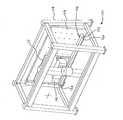
図1は、本発明の例示的実施形態に従った断熱板ガラスユニット10の斜視図である。断熱板ガラスユニット10は、第1の面80と、第2の面82と、第1の面80と第2の面82との間に延びる周縁部84とを有する第1の窓板12を含む。図1の実施形態において、断熱板ガラスユニット10は、また、第1の面と第2の面とを有する第2の窓板14も含む。図1において、スペーサー16が、第1の窓板12の第2の面82と第2の窓板14の第1の面との間に介在していることが理解できる。スペーサーは、サッシ/枠の一部、又は通常の別個のスペーサーであり得る。 FIG. 1 is a perspective view of an insulating
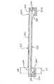
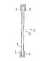
図2は、本発明の例示的実施形態に従った断熱板ガラスユニット10の断面図である。断熱板ガラスユニット10は、第1の窓板12と、第2の窓板14と、第1の窓板12と第2の窓板14との間に介在させたスペーサー16とを含む。ある実施形態におけるスペーサー16は、サッシ、枠等の不可欠な一部であり得る。断熱板ガラスユニットは、第1表面20と、第2表面22と、第3表面24と、第4表面26とを有する。図2に関し、第1の窓板12が、第1表面20と第2表面22とを含むことが理解されるであろう。図2の実施形態において、第1のコーティング18は、第1の窓板12の第1表面20上に配置される。また、図2の実施形態において、第2のコーティング28は、第1の窓板12の第2表面上に配置される。断熱板ガラスユニット10の第2の窓板14は、第3表面24と第4表面26とを含む。図2の実施形態において、第3のコーティング34は、第4表面26上に配置される。 FIG. 2 is a cross-sectional view of a thermal insulating
特に好ましいその他の実施形態において、二重窓板IGユニットの第1及び第2表面は、それぞれコーティング18、28を担持し、一方、第3及び第4表面はコーティングされていない。好ましくは、これらの特別な実施形態において、第1表面上のコーティング18は、第1のマスキング30を担持する(例えば、それによって被覆される)。付加的に又は代替的に、コーティングされていない第4表面26は、マスキング32を担持することができる。マスキング30、32の一方又は両方は、施される場合、剥離によって除去可能であることが好ましい。また、マスキング30、32の一方又は両方は、任意的に、複数の重ね合わされたマスキングストリップを含むことができ、重ね合わされたストリップは、任意的に、窓板に(そしてそれらの重ね合わされた部分を付着結合することにより互いに)付着結合されている。 In other particularly preferred embodiments, the first and second surfaces of the double pane IG unit carry
更にその他の実施形態において、二重窓板IGユニットの第1表面がコーティング18を担持し、一方、第2、第3及び第4表面はコーティングされていない。好ましくは、これらの実施形態において、第1表面上のコーティング18は、第1のマスキング30を担持する。付加的に又は代替的に、コーティングされていない第4表面26は、マスキング32を担持することができる。本実施形態における第2表面は、任意的に、コーティングを担持することができる。マスキング30、32の一方又は両方は、施される場合、剥離によって除去可能であることが好ましい。また、マスキング30、32の一方又はそれぞれは、任意的に、図4及び図6に示されているように配置された複数の重ね合わされたマスキングストリップを含むことができる。 In yet other embodiments, the first surface of the double pane IG unit carries the
好ましくは、コーティング18は、以下に記載の何れか1つのような光触媒コーティングである。代替的に、第1のコーティング18は、現在公知であるか後に開発されるかに関わらず、自浄機能を有する他のタイプのコーティング(すなわち、何らかの手動ワイピングの前であっても、コーティングされた窓板表面が少なくとも幾分清浄であるようにする機構及び/又は特性を有するあらゆるコーティング)であり得る。別の実施形態において、コーティング18は、親水性の非光活性コーティング(任意的に、シリカを含むコーティング)である。 Preferably, the
IGユニットの第4表面がコーティングされる実施形態において、このコーティングは、光触媒コーティング、又は、水をシート状にするシリカコーティングのような非光触媒親水性コーティングであり得る。例示的な水をシート状にするシリカコーティング(と有用な堆積装置及び方法)が、米国特許出願第09/868,542号に記載されており、その全教示は、ここに参照することにより組み込まれている。 In embodiments where the fourth surface of the IG unit is coated, the coating can be a photocatalytic coating or a non-photocatalytic hydrophilic coating such as a silica coating that turns water into a sheet. An exemplary water sheeted silica coating (and useful deposition apparatus and method) is described in US patent application Ser. No. 09 / 868,542, the entire teachings of which are incorporated herein by reference. It is.
図2の実施形態において、第2表面に代替的にコーティングしないで、第3表面にコーティングすることができる。代替的に、図2の実施形態を、第2及び第3表面の両方にコーティングしないよう変更することができる。更なる変形例として、第2及び第3表面の両方にコーティングすることができる。 In the embodiment of FIG. 2, the third surface can be coated without alternatively coating the second surface. Alternatively, the embodiment of FIG. 2 can be modified so that it does not coat both the second and third surfaces. As a further variation, both the second and third surfaces can be coated.
第2及び/又は第3表面がコーティングされる実施形態において、これらのコーティングは、有利に、低放射率コーティング及び/又は太陽光制御コーティングであり得る。例示的な低放射率が、米国特許出願第10/759,971号に記載されており、その全内容は、ここに参照することにより組み込まれている。これらのコーティングは、一般的に、2層の透明誘電フィルムの間に位置した銀又は銀含有フィルムを含む。例示的な太陽光制御コーティングが、米国特許第5,698,262号に記載されており、その全内容は、ここに参照することにより組み込まれている。 In embodiments where the second and / or third surfaces are coated, these coatings can advantageously be low emissivity coatings and / or solar control coatings. Exemplary low emissivity is described in US patent application Ser. No. 10 / 759,971, the entire contents of which are hereby incorporated by reference. These coatings typically comprise a silver or silver containing film located between two layers of transparent dielectric film. An exemplary solar control coating is described in US Pat. No. 5,698,262, the entire contents of which are hereby incorporated by reference.
一実施形態は、紫外線放射が保護マスキングの下地フィルムである光触媒フィルムに届くことを実質的に妨げるのに充分なだけ、紫外線放射に対して不透明であるよう(例えば、30%未満の紫外線透過率を有するよう)選択される除去可能な保護マスキングを提供する。そのような、ある場合において、不透明マスキングフィルムが提供される。 One embodiment appears to be opaque to UV radiation (e.g., less than 30% UV transmission) sufficient to substantially prevent UV radiation from reaching the photocatalytic film that is the underlying film of the protective masking. To provide a removable protective mask that is selected. In such cases, an opaque masking film is provided.
図2において、第1のマスキング30は、第1のコーティング18の上に重なり、任意の第2のマスキング32は、第4のコーティング36の上に重なっている。各マスキングは、好ましくは、基材38と接着剤層40とを含む。ある有用な実施形態において、接着剤層40は、アクリル接着剤を含む。ある有用な実施形態において、接着剤層40は、少なくとも1種の紫外線安定剤を含む。特別な一実施形態群は、少なくとも1種の紫外線安定剤を含むアクリル接着剤を含む接着剤層40を提供する。 In FIG. 2, a first masking 30 overlies the
ある有用な実施形態において、接着剤層40は、少なくとも1種のヒンダードアミンを含む。ある用途において好適であるかもしれないヒンダードアミンの例としては、ビス−(2,2,6,6−テトラメチル−4−ピペリジル)セバケート、ビス−(1,2,2,6,6−ペンタメチル−4−ピペリジル)セバケート、コハク酸とN−(2−ヒドロキシエチル)−4−ヒドロキシ−2,2,6,6−テトラメチルピペリジンの重縮合物、ポリ−([6−[(1,1,3,3−テトラメチルブチル)−イミノ]−1,3,5−トリアジン−2,4−ジイル][2−(2,2,6,6−テトラメチル−4−ピペリジル)イミノ]−ヘキサメチレン−[4−(2,2,6,6−テトラメチル−4−ピペリジル)イミノ])、l−[2−[3−(3,5−ジ−t−ブチル−4−ヒドロキシフェニル−プロピオニルオキシ)エチル]−4−[3−(3,5−ジ−t−ブチル−4−ヒドロキシフェニル)−プロピオニルオキシ]−2,2,6,6−テトラメチルピペリジン、テトラキス(2,2,6,6−テトラメチル−4−ピペリジル)−1,2,3,4−ブタンテトラカルボン酸エステル類、テトラキス(l,2,2,6,6−ペンタメチル−4−ピペリジル)−l,2,3,4−ブタンテトラカルボン酸エステル類、N,N’−ビス(2,2,6,6−テトラメチル−4−ピペリジル)ヘキサメチレンジアミンと1,2−ジブロモエタンの重縮合物、及び1,6−ビス−(2,2,6,6−テトラメチル−4−ピペリジルアミノ)ヘキサンと2,4−ジハロ−6−モルホリノ−l,3,5−トリアジンの重縮合物が挙げられる。接着剤層40は、この段落において上記に列挙したものからなる群から選択される1つのような、少なくとも1つのヒンダードアミンを含むアクリル接着剤であってもよい。接着剤40は、任意的に、1種以上のテトラメチルピペリジン誘導体を含むヒンダードアミンを含むことができる。 In some useful embodiments, the
本発明の好ましい実施形態において、第1のコーティング18は、光触媒フィルムを含む少なくとも1つの領域又は厚さを含む。光触媒フィルムは、酸化チタン(例えば、TiO2)のようなあらゆる光活性材料を含むことができる(例えば、それであり得る)。光活性材料は、特徴として、少なくとも上記特定の最小厚さを超えて、紫外線放射を吸収し、光触媒フィルムに接触する有機材料を光触媒作用で分解する能力を有するものであることが好ましい。特定の実施形態において、マスキング接着剤及び光触媒フィルムは、互いに補足し合うように一緒に選択される。ある場合において、光触媒フィルムの光活性は、大きな自浄効果を生み出すことなく、親水性をもたらすにちょうど足るだけの強さのものである。特に強力な光触媒フィルムを設けることは、そのようなフィルムがコーティング表面を理想的ではないほどに汚れて見える状態にする傾向がある点から、理想的とは言えないことが分かっている。光触媒フィルムは、任意的に、マスキング除去後、第1のコーティング上に残った接着剤の残留物を分解することができるにちょうど足るだけの高さの光活性レベルを有するように選択され得る。In a preferred embodiment of the present invention, the
特定の実施形態は、(モノリシック板ガラスアッセンブリ又は多重窓板断熱板ガラスユニットの)窓板と、その主表面の直上に、非常に薄膜である光触媒コーティング(例えば、光触媒フィルムを含む少なくとも1つの領域又は厚さを有するコーティング)と、その直上にマスキング接着剤の層と、その直上にマスキング基材(例えば、可撓性のある自立フィルムであって、好ましくは、このフィルムがコーティングされた主表面から剥離される時、接着剤が、マスキングフィルムに優先的に付着し、コーティングされた主表面に少なくとも実質的には転写されないように、コーティングされた主表面から剥離可能なフィルム)とを含むマスキングされた光触媒板ガラスアッセンブリを提供する。従って、マスキング接着剤40は、マスキング基材に対して、窓板のコーティング表面に対するよりも強力な付着レベル(又は力)を有することが好ましい。例えば、ある実施形態において、除去可能な保護マスキングは、剥離可能なマスキングであり、マスキング接着剤は、マスキング基材に対して、光触媒コーティングに対するよりも高レベルの付着力を有し、その結果、マスキングがコーティングされた主表面から剥離される時、接着剤がマスキング基材に優先的に付着する。これらの実施形態において、マスキング基材38及び/又はマスキング接着剤40は、任意的に、少なくとも1種の紫外線安定剤及び/又は少なくとも1種の紫外線遮断剤を含む。好ましくは、紫外線安定剤は、接着剤に混合される。 Certain embodiments include a window plate (of a monolithic pane glass assembly or multiple pane insulation panel glass unit) and a photocatalyst coating that is a very thin film (eg, at least one region or thickness comprising a photocatalyst film) directly over its major surface. And a masking adhesive layer directly thereon, and a masking substrate (eg, a flexible free-standing film, preferably peeled from the main surface on which the film is coated) The adhesive is preferentially attached to the masking film and is at least substantially not transferred to the coated main surface such that the adhesive is peelable from the coated main surface). A photocatalyst plate glass assembly is provided. Accordingly, the masking
望ましくは、光触媒フィルムの光活性レベルは、充分低く、そのため、接着剤とマスキングフィルムとの間の接着状態、又は接着剤と窓板との間の接着状態を破壊することがないであろう。従って、好ましくは、接着剤がコーティング18の光活性によって受け入れられないほどに劣化することによって、マスキングフィルムが窓板から剥がれて落ちたり、又はたるんだりすることがない。任意的に、光触媒フィルムは、マスキング30が除去される時、コーティング18上に残った接着剤の残留物を分解することができるにちょうど足るだけの高さの光活性レベルを有するよう選択され得る。好ましくは、マスキング接着剤は、マスキングが除去される時、接着剤の転写が起こらないよう選択される。 Desirably, the photoactive level of the photocatalytic film is sufficiently low so that it does not destroy the adhesion between the adhesive and the masking film or between the adhesive and the window plate. Thus, preferably, the masking film does not peel off or sag from the window pane due to unacceptable degradation of the adhesive by the photoactivity of the
この開示を目的として、光触媒フィルムの活性を、所望の光触媒反応速度について、例えば、フィルム表面において1平方メートル当り約20ワットの強度を有する(例えば、米国オハイオ州、クリーヴランドのQパネル社(Q−panel Company)により商標UVA−340として市販の)光源からの紫外線放射に露光されたステアリン酸テストフィルムを除去して、測定することができる。紫外線放射強度は、テスト対象となっている光触媒フィルムのコーティング表面において、少なくとも1平方メートル当り約20ワットであり得る。強度は、任意的に、米国カリフォルニア州、サンガブリエルのウルトラヴァイオレットプロダクツ社(Ultraviolet Products, Inc.)によって(例えば、商標BLACK−RAYとして)販売されているもののような紫外線強度計を用いて設定することができる。光源は、テスト対象となっている光触媒フィルムのコーティング表面に対して垂直に位置付けることができる。例示的な方法が、米国特許第6,027,766号に説明されており、その全内容は、ここに参照することにより組み込まれている。 For the purposes of this disclosure, the activity of the photocatalytic film is determined for the desired photocatalytic reaction rate, for example, having an intensity of about 20 watts per square meter at the film surface (eg, Q-Panel, Cleveland, Ohio, USA). (Company) can be measured by removing the stearic acid test film exposed to ultraviolet radiation from a light source (commercially available under the trademark UVA-340). The ultraviolet radiation intensity can be at least about 20 watts per square meter on the coating surface of the photocatalytic film being tested. Intensity is optionally set using a UV intensity meter such as that sold by Ultraviolet Products, Inc. of San Gabriel, California, USA (eg, under the trademark BLACK-RAY). be able to. The light source can be positioned perpendicular to the coating surface of the photocatalytic film being tested. An exemplary method is described in US Pat. No. 6,027,766, the entire contents of which are hereby incorporated by reference.
簡潔には、光触媒フィルムと紫外線放射源とは、紫外線放射が、まず光触媒フィルムを通り、次に基材を通るように、互いに対して相対的に位置付けることができる。この場合、光源は、コーティングされた窓板のおもてに面している。窓板が、紫外線放射が通過可能な材料(例えば、ガラス)からなる場合、光触媒フィルムと紫外線放射源とは、紫外線放射が、まず窓板を通り、次に光触媒フィルムを通るように、互いに対して相対的に位置付けることができる。この場合、光源面は、コーティングされた窓板のうらに面している。代替的に、光源は、窓板の両面上に位置付けることができる。 Briefly, the photocatalytic film and the ultraviolet radiation source can be positioned relative to each other such that the ultraviolet radiation first passes through the photocatalytic film and then through the substrate. In this case, the light source faces the front of the coated window pane. When the window pane is made of a material that can pass ultraviolet radiation (eg, glass), the photocatalytic film and the ultraviolet radiation source are relative to each other such that the ultraviolet radiation passes first through the window pane and then through the photocatalytic film. Can be relatively positioned. In this case, the light source surface faces the back of the coated window pane. Alternatively, the light sources can be located on both sides of the window pane.
更に詳細には、有機汚染物質を光触媒フィルムの上を覆って付し、フィルムに照射すると、フィルムの汚染物質を除去する能力を観察及び測定することができる。ステアリン酸(CH3(CH2)16COOH)は1つの有用な汚染物質である。ステアリン酸は、スプレーコーティング、ディップコーティング、又はスピンコーティングのようなあらゆる所望の技術によって、薄膜テストフィルムとして、光触媒フィルムの上を覆って付すことができる。ステアリン酸テストフィルム厚は、任意的に、約100オングストローム以上、約200オングストローム以下の範囲であり得る。テストフィルムは、例えば、溶液1リットル当り6×10⁻³モルのステアリン酸濃度を有する溶液のようなメタノール溶液内のステアリン酸として付すことができる。
More specifically, when an organic contaminant is applied over the photocatalytic film and the film is irradiated, the ability of the film to remove the contaminant can be observed and measured. Stearic acid (CH3 (CH2 )16 COOH) is one useful contaminant. Stearic acid can be applied over the photocatalytic film as a thin film test film by any desired technique such as spray coating, dip coating, or spin coating. The stearic acid test film thickness can optionally range from about 100 angstroms to about 200 angstroms. The test film can be applied, for example, as stearic acid in a methanol solution, such as a solution having a stearic acid concentration of 6× 10⁻³ moles per liter of solution.
報告されている光触媒フィルムの活性を測定する方法は、光触媒フィルム上のステアリン酸の炭素−水素伸縮振動吸収帯の積分強度を測定することである。積分強度は、光触媒フィルム上のステアリン酸テストフィルムの厚さを反映する。ステアリン酸テストフィルムが除去されると、炭素−水素伸縮振動帯強度が低下することになると考えられている。ステアリン酸中の炭素−水素結合は、紫外線放射とは異なり、光触媒フィルムを活性化させない赤外線放射を吸収する。一般に、そのような吸収は、2800cm-1以上、3000cm-1以下の波数で起こり、フーリエ変換赤外分光光度計を用いて測定可能である。この分光光度計は、重水素化トリグリシンスルフェート検出器又は水銀カドミウムテルル化物検出器のような検出器を備えることができる。水銀カドミウムテルル化物検出器は、特に、窓板、光触媒フィルム、又は窓板上の他のフィルムが、分光光度計が吸収スペクトルを生成するのに用いる赤外線放射を吸収する場合に好ましいことが報告されている。赤外線放射がそのように吸収される場合、ステアリン酸テストフィルムを通過する赤外線放射は減少する。このことは、光触媒フィルム上のステアリン酸が低濃度であることと結びついている。このことから、水銀カドミウムテルル化物検出器は、重水素化トリグリシンスルフェート検出器より約1桁優れた信号対雑音比を有するスペクトルを提供すると報告されている。光触媒フィルムの上を覆って堆積させたステアリン酸テストフィルムの活性がテストされる時、赤外線放射は、任意的に、窓板及び光触媒フィルムを通って、テスト対象となっている窓板の反対側の検出器上へと方向付けることができる。赤外線放射が基材を通過することができない場合、赤外線放射を、任意的に、表面の上方に傾斜して方向付け、テストフィルムを通過させ、窓板から反射させることができる。そのような方法は、反射赤外分光法として公知である。The reported method for measuring the activity of a photocatalytic film is to measure the integrated intensity of the carbon-hydrogen stretching vibration absorption band of stearic acid on the photocatalytic film. The integrated intensity reflects the thickness of the stearic acid test film on the photocatalytic film. It is believed that when the stearic acid test film is removed, the carbon-hydrogen stretching vibration band strength will decrease. The carbon-hydrogen bonds in stearic acid absorb infrared radiation that does not activate the photocatalytic film, unlike ultraviolet radiation. Generally, such absorption, 2800 cm-1 or more, occur at 3000 cm-1 following wavenumber, it can be measured using a Fourier transform infrared spectrophotometer. The spectrophotometer may comprise a detector such as a deuterated triglycine sulfate detector or a mercury cadmium telluride detector. Mercury cadmium telluride detectors are reported to be particularly preferred when window panes, photocatalytic films, or other films on window panes absorb infrared radiation used by spectrophotometers to generate absorption spectra. ing. If the infrared radiation is so absorbed, the infrared radiation passing through the stearic acid test film is reduced. This is linked to the low concentration of stearic acid on the photocatalytic film. From this, the mercury cadmium telluride detector is reported to provide a spectrum with a signal-to-noise ratio that is about an order of magnitude better than the deuterated triglycine sulfate detector. When the activity of the stearic acid test film deposited over the photocatalytic film is tested, the infrared radiation optionally passes through the window plate and the photocatalytic film to the opposite side of the window plate being tested. Can be directed onto the detector. If the infrared radiation cannot pass through the substrate, the infrared radiation can optionally be directed tilted above the surface, passed through the test film, and reflected from the window pane. Such a method is known as reflection infrared spectroscopy.
これにより、光触媒フィルムが化学線放射に露光される時、光触媒フィルムが反応してステアリン酸テストフィルムを除去する速度を測定することによって、光触媒フィルムの反応速度を考察することができる。炭素−水素伸縮振動特性の積分強度の低下率は、表面被覆率に正比例すると報告されている。従って、化学線(紫外線)放射に露光される時間を増加することによって、反応速度が得られる。光触媒フィルム18上のステアリン酸テストフィルムについて、分光光度計を用いて初期活性を測定することができる。光触媒フィルムは、任意的に、初期活性測定のために紫外線放射に露光しておくことができる。その後、ステアリン酸がコーティングされた光触媒フィルムを一定時間、紫外線放射に露光し、その最後に、分光光度計を用いて第2活性測定を行うことができる。ステアリン酸テストフィルムの一部が、紫外線放射に露光されることにより除去されているであろうことから、第2測定における炭素−水素伸縮振動の積分強度は、第1測定におけるよりも低いはずである。そのような2回の測定から、時間に対する炭素−水素伸縮振動の積分強度の曲線を作成することができる。そのような曲線の勾配によって、反応速度が得られる。2点をプロットして曲線が得られるが、何回かの測定を行って曲線を得るのが好ましい。測定を3回以上行う場合、各測定間の放射露光時間は一定に保つことも変化させることもできる(例えば、紫外線放射露光の累積時間を用いて曲線をプロットできる)が、反応速度を測定する場合、紫外線放射の強度及び向きは全ての測定について一定に保たねばならない。 Thus, when the photocatalytic film is exposed to actinic radiation, the reaction rate of the photocatalytic film can be considered by measuring the rate at which the photocatalytic film reacts and removes the stearic acid test film. It has been reported that the rate of decrease in the integrated intensity of the carbon-hydrogen stretching vibration characteristic is directly proportional to the surface coverage. Thus, by increasing the time exposed to actinic (ultraviolet) radiation, the reaction rate is obtained. The initial activity of the stearic acid test film on the
本発明の特定の実施形態は、低レベルの光活性を有し、マスキングフィルムが、直接(例えば、コーティング18とマスキング基材との間に挟まれたマスキング接着剤を介して)、光触媒コーティング18に接して担持される場合に用いられる光触媒コーティング18を提供する。ここで報告されている反応速度は、cm-1分-1を単位として示される。反応速度の値が大きいほど、光活性が大きいことを示す。特定の実施形態において、コーティング18は、1×10⁻²cm-1分-1未満、9×10⁻³cm-1分-1未満、8×10⁻³cm-1分-1未満、4×10⁻³cm-1分-1未満、3×10⁻³cm-1分-1未満、2×10⁻³cm-1分-1未満、又は更に約1.5×10⁻³cm-1分-1未満の光触媒活性を有する。
Certain embodiments of the present invention have a low level of photoactivity, and the masking film is directly (eg, via a masking adhesive sandwiched between the
一実施形態は、窓板(任意的に、ガラス窓板)であって、その第1の主表面の直接上を覆って(チタニアを含む、それを主成分とする、又はそれからなる活性フィルムを含み、活性フィルムが、好ましくは、約150オングストローム未満、例えば、20オングストローム以上100オングストローム以下、又は100オングストローム未満、或いは20オングストローム以上75オングストローム以下、及び、ある場合には、20オングストローム以上60オングストローム以下等、75オングストローム以下の厚さを有する)光触媒コーティング18が付された窓板を提供する。光触媒コーティング18は、好ましくは、(必ずではないが、任意的に、1つ以上の上記範囲内、例えば、9×10⁻³cm-1分-1未満、5×10⁻³cm-1分-1未満、又は更に約1.5×10⁻³cm-1分-1未満の)特に低い光触媒活性を有する。この場合、マスキングが、光触媒コーティング18によって(例えば、マスキングが、光触媒コーティング18とマスキング基材との間に直接挟まれるマスキング接着剤を含むように)担持される。これらの実施形態において、光触媒コーティング18(又は、少なくともそのチタニア含有フィルム)は、任意的に、スパッタフィルムであり得る。しかし、他の実施形態においては、光触媒コーティングは、化学気相蒸着、真空蒸着、及び/又はイオンアシスト蒸着のような、他の薄膜堆積技術によって付される。湿式化学法(例えば、ゾルゲル法)を用いることもできる。
One embodiment is a window pane (optionally a glass pane) that covers an active film (including, comprising, or consisting of titania) directly over its first major surface. The active film is preferably less than about 150 angstroms, such as 20 angstroms or more and 100 angstroms or less, or less than 100 angstroms, or 20 angstroms or more and 75 angstroms or less, and in some cases, 20 angstroms or more and 60 angstroms or less. A window pane with a photocatalytic coating 18 (having a thickness of 75 Angstroms or less). The
従って、特定の実施形態において、光触媒薄膜コーティングは、チタニアを含む活性フィルムを含み、活性フィルムは、100オングストローム未満、又は更に75オングストローム未満の厚さを有する。 Thus, in certain embodiments, the photocatalytic thin film coating comprises an active film comprising titania, the active film having a thickness of less than 100 angstroms, or even less than 75 angstroms.
光触媒コーティングが、スパッタフィルムを含む(例えば、それである)実施形態において、様々なスパッタ堆積技術を用いることができる。特定の特に好ましい実施形態において、光触媒コーティング18(又は、少なくとも1つのそのフィルム領域)は、低温で(例えば、基材を約摂氏250度より低温、及び、より好ましくは摂氏200度より低温に維持しながら)スパッタリングによって堆積される。 In embodiments where the photocatalytic coating includes (eg, is) a sputtered film, various sputter deposition techniques can be used. In certain particularly preferred embodiments, the photocatalytic coating 18 (or at least one film region thereof) is maintained at a low temperature (eg, the substrate is below about 250 degrees Celsius, and more preferably below 200 degrees Celsius). While) deposited by sputtering.
スパッタリングは、本技術分野において周知である。マグネトロンスパッタリングチャンバと関連装置が、様々な供給源(例えば、レイボルド(Leybold))から市販されている。有用なマグネトロンスパッタリング技術と装置が、チャピン(Chapin)に発行された米国特許第4,166,018号に記載されており、その全教示は、ここに参照することにより組み込まれている。 Sputtering is well known in the art. Magnetron sputtering chambers and associated equipment are commercially available from a variety of sources (eg, Leybold). Useful magnetron sputtering techniques and equipment are described in US Pat. No. 4,166,018 issued to Chapin, the entire teachings of which are incorporated herein by reference.
本発明の特定の好ましい方法において、光触媒コーティング18は、マルチチャンバスパッタリングラインにおいて基材に付される。スパッタリングラインは、本技術分野において周知である。典型的なスパッタリングラインは、シート状基材を、各チャンバにおいて間隔を置いて配置された移送ローラー(ローラーは、スパッタリングラインを通る連続した基材走行路を構成する)の上方を(例えば、それに直接接触しながら)水平に搬送することによって、基材を1つのチャンバから次のチャンバへと通過させることができるように位置合わせされ、連結された一連のスパッタリングチャンバを含む。基材は、典型的には、1分間当り約100から500インチの速度で搬送される。 In certain preferred methods of the invention, the
特定の一方法において、基材は、スパッタリングラインの入口に位置付けられ、所望のコートゾーンに搬送される。このコートゾーンは、第1のフィルムを堆積させるのに適合させた3つの陰極を備えている。より詳細には、これらの陰極はそれぞれ、ケイ素スパッタリングターゲットを含むが、その他の方法では第1のフィルムの材料としてその他の材料が含まれる(代替的に、この第1のフィルムを全く施さないでおくことができる)。このコートゾーンにおけるケイ素ターゲットを、酸化雰囲気においてスパッタし、基材の第1の主表面の直上に二酸化ケイ素フィルムを堆積させることができる。この雰囲気は、酸素(例えば、約100%のO2)を主成分としてもよい。代替的に、この雰囲気は、Ar/O2(例えば、酸素と約40%までのアルゴン)を含んでもよい。約38kWの電力を第1の陰極に印加し、約38kWの電力を第2の陰極に印加し、約38kWの電力を第3の陰極に印加することができる。基材は、これら全3つのターゲットの下方を、これらのターゲットそれぞれを言及した電力レベルでスパッタしながら、1分間に約200インチの速度で搬送可能であり、その結果、二酸化ケイ素フィルムが約100Åの厚さで付される。この場合のシリカフィルムは、任意的に、100オングストローム未満、例えば、約75オングストローム等、60オングストローム以上90オングストローム以下であり得る。この任意の第1のフィルムの厚さ及び組成は、所望に応じて変更可能である。1つ以上のケイ素ターゲットが用いられる実施形態において、各ケイ素ターゲットは、ターゲットの導電性を高めるため、多少のアルミニウム又は他の材料を含み得る。
In one particular method, the substrate is positioned at the entrance of the sputtering line and transported to the desired coating zone. This coat zone comprises three cathodes adapted to deposit the first film. More specifically, each of these cathodes includes a silicon sputtering target, but other methods include other materials as the material of the first film (alternatively, the first film is not applied at all). Can be left). The silicon target in this coating zone can be sputtered in an oxidizing atmosphere to deposit a silicon dioxide film directly above the first major surface of the substrate. This atmosphere may contain oxygen (for example, about 100% O2 ) as a main component. Alternatively, the atmosphere may include Ar / O 2 (eg, oxygen and up to about 40% argon). About 38 kW of power can be applied to the first cathode, about 38 kW of power can be applied to the second cathode, and about 38 kW of power can be applied to the third cathode. The substrate can be transported at a rate of about 200 inches per minute while sputtering below all three targets at the power level mentioned for each of these targets, so that the silicon dioxide film is about 100 It is subjected to a thickness ofÅ. The silica film in this case can optionally be less than 100 angstroms, such as about 75 angstroms or more and 60 angstroms or more and 90 angstroms or less. The thickness and composition of this optional first film can be varied as desired. In embodiments where one or more silicon targets are used, each silicon target may include some aluminum or other material to increase the conductivity of the target.
このようにコーティングされた基材は、その後、次のコートゾーンへ搬送され得る。このゾーンにおいて、3つの陰極を用いて第2のフィルムを堆積させる。好ましくは、これら3つの陰極はそれぞれ、チタンスパッタリングターゲットを含む。このコートゾーンにおけるチタンターゲットを、酸化雰囲気においてスパッタし、任意の第1のフィルムが設けられる場合、その直上に二酸化チタンフィルムを堆積させることができる。代替的に、そのような二酸化チタンフィルムは、基材の直上に堆積させることができる。更に、基材と二酸化チタンフィルムとの間に2層以上のフィルムを堆積させることができる。二酸化チタンフィルムを堆積させる雰囲気は、酸素を主成分としてもよい。代替的に、この雰囲気は、Ar/O2を含んでもよい。約43kWの電力を第1の陰極に印加し、約43kWの電力を第2の陰極に印加し、約43kWの電力を第3の陰極に印加することができる。基材は、これら全3つのターゲットの下方を、これらのターゲットそれぞれを言及した電力レベルでスパッタしながら、1分間に約200インチの速度で搬送可能であり、その結果、二酸化チタンフィルムが約100Aの厚さで付される。この場合のチタニアフィルムは、任意的に、100オングストローム未満、例えば、約25から40オングストローム等、20オングストローム以上60オングストローム以下であり得る。このフィルムの厚さ及び組成は、変更可能である。本方法において、この二酸化チタンは、コーティング18の最外部を構成するが、その他の実施形態は、二酸化チタンによって付与された親水性を排除しない、その上に重なる薄膜を含む。特定の親水特性(例えば、夜間特性(night−time properties))を実現するために、チタニアは、任意的に、シリカ(又は、他の、非光活性であるが、親水性である誘電性材料)と混合可能である。これは、親水特性と光活性特性の所望の均衡を実現するために行うことができ、これによって、適切に低レベルな、良好なマスキング耐久性を向上させる能力が得られる場合がある。コーティング18の最外面の直接上を覆って、第1のマスキング30が付着するように付されていることが好ましい。このマスキング30は、単一マスキング材料シートとして、又は、一連に重なり合うように付された複数の細長いマスキングストリップであって、隣接するストリップが(例えば、図4に図示されているように)側端が互いに重なり合う配置で重ねられた複数のストリップとして、付すことができる。任意的に、マスキングされた窓板表面は、(例えば、マスキングされた窓板表面領域のちょうど中心を含む)中央領域を有し、付着した1つ以上のマスキングストリップがこの中央領域の上方に(例えば、それを覆い、それを越えて延びるように)位置する。
The substrate coated in this way can then be transported to the next coat zone. In this zone, a second film is deposited using three cathodes. Preferably, each of these three cathodes includes a titanium sputtering target. When the titanium target in this coat zone is sputtered in an oxidizing atmosphere and an arbitrary first film is provided, a titanium dioxide film can be deposited directly thereon. Alternatively, such a titanium dioxide film can be deposited directly on the substrate. Furthermore, two or more layers of films can be deposited between the substrate and the titanium dioxide film. The atmosphere in which the titanium dioxide film is deposited may contain oxygen as a main component. Alternatively, the atmosphere may comprise Ar / O2. About 43 kW of power can be applied to the first cathode, about 43 kW of power can be applied to the second cathode, and about 43 kW of power can be applied to the third cathode. The substrate can be transported at a rate of about 200 inches per minute while sputtering below all three targets at the power level mentioned for each of these targets, resulting in a titanium dioxide film of about 100 A. It is attached with a thickness of. The titania film in this case can optionally be less than 100 angstroms, for example about 20 to 60 angstroms, such as about 25 to40 angstroms. The thickness and composition of the film can be varied. In this method, the titanium dioxide constitutes the outermost portion of the
説明したばかりの方法において、基材の第2の主面が、任意の低放射率コーティングで予めコーティングされている、又は後にコーティングされてもよいことが理解されるべきである。例えば、説明したばかりの、第1及び第2のフィルムを堆積させるのに用いられるコートゾーンは、(例えば、そこで任意の低放射率コーティングが予め付されてもよい先行する比較的多数の下向きスパッタコートゾーンを含むスパッタリングラインの終端に任意的に位置する)上向きスパッタコートゾーンであり得る。特に有用な上向きスパッタ/下向きスパッタ法及び装置が、米国特許出願第09/868,542号に記載されており、その全内容は、ここに参照することにより組み込まれている。 It should be understood that in the method just described, the second major surface of the substrate may be pre-coated with any low emissivity coating, or later coated. For example, the coating zone used to deposit the first and second films just described is a relatively large number of preceding downsputters (e.g., where any low emissivity coating may be pre-applied). It may be an upward sputter coating zone (optionally located at the end of the sputtering line containing the coating zone). A particularly useful upward / downward sputtering method and apparatus is described in US patent application Ser. No. 09 / 868,542, the entire contents of which are hereby incorporated by reference.
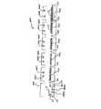
特定の実施形態において、本発明は、マスキングされた光触媒断熱ガラス技術に関する高効率な製造工程を提供する。ここで、この方法は、第1段階としてのスパッタ堆積工程を含み,第2段階としてのマスキングを付す工程がこれに続く。マスキングは、任意的に、断熱ガラスユニットアッセンブリラインの一部であるマスキングステーションを操作することによって付される。図11の工程及び図12のコーターを参照する。好ましくは、この工程は、第1のガラス板をコーター(例えば、連続した基材走行路に沿って一連に連結された複数の堆積区画/チャンバを含むコーター)に通して搬送することと、ガラス板の第1の主表面を上向きスパッタリングによってコーティングすることと、ガラス板の第2の主表面を下向きスパッタリングによってコーティングすることとを含み、その後、このようにコーティングされた第1のガラス板は、断熱ガラスユニットアッセンブリラインに沿って搬送され、その上で第1のガラス板が第2のガラス板と組み合わされて断熱ガラスアッセンブリを構成し、その後、マスキング接着剤を第1のガラス板のコーティングされた第1の表面に直接付着させることによって、剥離可能な第1のマスキングが、第1のガラス板のコーティングされた第1の表面の上を覆って付される。ある実施形態において、この場合、マスキングは、断熱ガラスユニットアッセンブリラインの一部であるマスキングステーションを操作することによって付される。一実施形態において、このマスキングステーションは、アッセンブリラインの終端に位置する。 In certain embodiments, the present invention provides a highly efficient manufacturing process for masked photocatalytic insulation glass technology. Here, this method includes a sputter deposition process as a first stage, followed by a process of applying masking as a second stage. Masking is optionally applied by operating a masking station that is part of the insulated glass unit assembly line. Reference is made to the process of FIG. 11 and the coater of FIG. Preferably, this step comprises conveying the first glass plate through a coater (eg, a coater comprising a plurality of deposition compartments / chambers connected in series along a continuous substrate path) and glass Coating the first major surface of the plate by upward sputtering and coating the second major surface of the glass plate by downward sputtering, after which the first glass plate thus coated comprises: It is transported along the insulating glass unit assembly line, on which the first glass plate is combined with the second glass plate to form the insulating glass assembly, and then the masking adhesive is coated on the first glass plate. By attaching directly to the first surface, the first mask that can be peeled off becomes the coating of the first glass plate. Subjected overlying the Ingu been first surface. In certain embodiments, in this case, masking is applied by manipulating a masking station that is part of the insulated glass unit assembly line. In one embodiment, the masking station is located at the end of the assembly line.
図12は、本製造工程において有用である例示的なコーター2000を示したものである。ここで、コーター2000は、このことは要件ではないが、少なくとも6つのスパッタ堆積区画を含むことが分かる。コーターは、少なくとも9つのそのような区画、少なくとも12のそのような区画、又は更に少なくとも15のそのような区画を有利に含んでもよい。図示されたコーターは、その最後の区画200(すなわち、基材走行路に沿う最後の活性な区画)に、上向きスパッタ区画/チャンバを有する。他の実施形態において、コーターは、基材走行路P上の第1の活性な区画としての上向きスパッタ区画/チャンバを有する。図示されたチャンバ2000は、移送ローラー210とコンベアベルト144Cから144Gとの組み合わせを有することが示されているが、単に、間隔を置いて配置された(コンベアベルトによって連結されていない)移送ローラー210を用いるのが好ましい場合がある。図示されているコーターにおいて、最初の5つの区画は下向きスパッタ区画であり、一方、最後の区画は上向きスパッタ区画である。しかし、上述したように、上向きスパッタ区画及び下向きスパッタ区画の配置及び位置は、効率又は製品品質が最大限となるよう調整可能である。図示された各区画は、このことは決して要件ではない(例えば、ある特定のチャンバは、所望の工程次第で、ターゲットを1つ有しても、ターゲットを3つ以上を有しても、又はターゲットなしでもよい)が、2つのターゲット166Aから166J、660A、660Bを備える。 FIG. 12 shows an exemplary coater 2000 that is useful in the manufacturing process. Here, it can be seen that the coater 2000 includes at least six sputter deposition sections, although this is not a requirement. The coater may advantageously include at least 9 such compartments, at least 12 such compartments, or even at least 15 such compartments. The illustrated coater has an upward sputter compartment / chamber in its last compartment 200 (ie, the last active compartment along the substrate path). In other embodiments, the coater has an upward sputter compartment / chamber as the first active compartment on the substrate runway P. The illustrated chamber 2000 is shown having a combination of
一実施形態群は、基材を加工する方法を提供し、この方法は、第1のガラス板を準備することと、この板を単一のスパッタコーターに通して搬送することと、ガラス板をスパッタコーターに一度だけ通して、この板の第1及び第2の両主表面上にコーティングをスパッタ堆積させることとを含む。本実施形態群において、このスパッタ堆積は、第1のターゲットシーケンス660A、660Bから上向きにスパッタすることによって、ガラス板12の第1の主表面20に光触媒コーティングを付すことを含む。ここで、第1のターゲットシーケンスは、任意的に、純粋な、又は実質的に純粋なチタン材料、チタン合金材料、酸化チタン材料、及びチタンとケイ素とを含む化合物からなる群から選択されるスパッタ可能な材料を含む1つ以上のターゲットを含む。この上向きスパッタリングは、任意的に、酸化ガス及び/又は不活性ガスを含有するガススパッタリング雰囲気において行うことができる。好適なターゲットは、米国ミシガン州、ニューハドソン、ティコチタニウム社(TICO Titanium Inc.)のような多くの供給源から市販されている。不足当量TiOxターゲット、但しxは2未満、について、米国特許第6,461,686号及び第6,468,402号及び第6,511,587号に記載されており、それぞれの全内容は、ここに参照することにより組み込まれている。不足当量TiOxターゲットは、べカールト社(Bekaert VDS nv)(ベルギー国、デーンズ)から市販されている。連帯的に、スパッタ堆積は、第2のターゲットシーケンスから下向きにスパッタすることによって、第1のガラス板の第2の主表面に低放射率コーティングを付すことを含む。ここで、第2のターゲットシーケンスは、任意的に、純粋な、又は実質的に純粋な銀材料及び銀合金材料からなる群から選択されるスパッタ可能な材料を含む1つ以上のターゲットを含む。この性質の好適なターゲットは、多くの商業的供給源から容易に入手可能である。このようにコーティングされた第1のガラス板は、その後、多重窓板絶縁板ガラスユニットアッセンブリラインに送られ(例えば、その上に位置付けられ)、アッセンブリラインに沿って搬送され、その上で、この第1のガラス板は、第2のガラス板と、得られる断熱ガラスアッセンブリが第1のガラス板と第2のガラス板との間の間隙を規定する(第1のガラス板のコーティングされた第1の主表面が間隙とは反対側にある外表面である)ように、組み合わされる。剥離可能な第1のマスキングが、光触媒コーティングの上を覆って付される。マスキングは、好ましくは、マスキング基材とマスキング接着剤とを含む。第1のマスキングを光触媒コーティングの上を覆って付すことは、マスキング接着剤を光触媒コーティングに直接付着させることを含む。付されたマスキング接着剤は、マスキング基材に対して、光触媒コーティングに対するよりも高レベルの付着力を有するよう選択されることが望ましい。ある場合には、第1のマスキングを光触媒コーティングの上を覆って付すことは、アッセンブリラインの一部(すなわち、その上に位置する)第1のマスキングステーションを操作することを含む。任意的に、本方法は、有利に、やはりアッセンブリラインの一部であり得る第2のマスキングステーションを操作することによって、剥離可能な第2のマスキングを、得られる断熱ガラスアッセンブリの第4表面の上を覆って付すことを含む。One group of embodiments provides a method of processing a substrate, comprising preparing a first glass plate, transporting the plate through a single sputter coater, Pass through the sputter coater only once and sputter deposit the coating on both the first and second major surfaces of the plate. In this group of embodiments, this sputter deposition includes applying a photocatalytic coating to the first
直前の段落に記載の実施形態の幾つかにおいて、光触媒コーティングは、チタニアを含有する活性フィルムを含み、この活性フィルムは、以下に記載するように、100オングストローム未満の厚さにスパッタ堆積される。付加的に又は代替的に、光触媒コーティングは、任意的に、チタニアを含有する活性フィルムを含むことができ、この活性フィルムは、非晶質フィルムの直接上を覆ってスパッタ堆積させることができる。 In some of the embodiments described in the immediately preceding paragraph, the photocatalytic coating comprises an active film containing titania, which is sputter deposited to a thickness of less than 100 angstroms, as described below. Additionally or alternatively, the photocatalytic coating can optionally include an active film containing titania, which can be sputter deposited directly over the amorphous film.
本実施形態群において、この方法は、第1のマスキングを、光触媒コーティングを担持する主表面から剥離することを更に含むことができる。この剥離中、ある実施形態における接着剤は、ひとたび第1のマスキングが光触媒コーティングを担持する主表面から剥離されると、接着剤の実質的に全てがマスキング基材上に残るように、マスキング基材に優先的に付着する。上述したように、マスキング接着剤は、任意的に、アクリル接着剤であることができ、及び/又はマスキング基材は、任意的に、ポリエチレンを含むことができ、及び/又はマスキング接着剤は、任意的に、少なくとも1種の紫外線安定剤を含むことができる。 In this group of embodiments, the method can further include stripping the first mask from the major surface carrying the photocatalytic coating. During this stripping, the adhesive in certain embodiments is such that once the first mask is stripped from the major surface carrying the photocatalytic coating, substantially all of the adhesive remains on the masking substrate. Preferentially adheres to the material. As noted above, the masking adhesive can optionally be an acrylic adhesive, and / or the masking substrate can optionally comprise polyethylene, and / or the masking adhesive can be Optionally, at least one UV stabilizer can be included.
特に薄膜である(任意的に、スパッタされたチタニアを含む)光触媒コーティングは、上記特徴及び利点に関する限りにおいて、格別な効果をもたらし得ることが分かっている。ある実施形態において、光触媒コーティングの全厚は、約500オングストローム未満、好ましくは約400オングストローム未満、或いは約300オングストローム未満、又は更に200オングストローム未満(例えば、20オングストローム以上、175オングストローム以下)である。 It has been found that photocatalytic coatings, particularly thin films (optionally including sputtered titania), can provide exceptional effects as far as the above features and advantages are concerned. In certain embodiments, the total thickness of the photocatalytic coating is less than about 500 angstroms, preferably less than about 400 angstroms, or less than about 300 angstroms, or even less than 200 angstroms (eg, greater than or equal to 20 angstroms and less than or equal to 175 angstroms).
特定の実施形態は、チタニアを含む活性フィルムを含む光触媒薄膜コーティングを含み、活性フィルムは、200オングストローム未満、100オングストローム未満、又は更に75オングストローム未満の厚さを有する下地フィルムの直接上を覆って堆積される。更に、ある場合には、チタニア含有フィルムは、それと基材との間に、全体で、200オングストローム以下、又は100オングストローム以下の下地フィルムを有する。 Certain embodiments include a photocatalytic thin film coating comprising an active film comprising titania, wherein the active film is deposited directly over an underlying film having a thickness of less than 200 angstroms, less than 100 angstroms, or even less than 75 angstroms. Is done. Further, in some cases, the titania-containing film has a total base film of 200 angstroms or less, or 100 angstroms or less, between it and the substrate.
ある実施形態において、光触媒薄膜コーティングは、チタニアを含む活性フィルムを含み、活性フィルムは、非晶質フィルムの直接上を覆って堆積される(すなわち、位置付けられる)。非晶質フィルムは、例えば、任意的に、1種以上の金属(例えば、アルミニウム)を含むシリカフィルムであり得る。ある場合には、非晶質フィルムは、ガラスの風冷強化時、少なくとも実質的に非晶質であるという形態を維持するよう適合させた組成を有する。シリカと少量の1種以上の金属とを含むフィルムが有用である。従って、図2において、例えば、コーティング18の最内厚(すなわち、第1の窓板12に最も近接する厚さ)は、活性チタニア含有フィルム(任意的に、コーティング18の最外厚を構成する活性フィルム)の下地フィルムであり得る。 In certain embodiments, the photocatalytic thin film coating comprises an active film comprising titania, and the active film is deposited (ie, positioned) directly over the amorphous film. The amorphous film can be, for example, a silica film that optionally includes one or more metals (eg, aluminum). In some cases, the amorphous film has a composition adapted to maintain a form that is at least substantially amorphous upon air-cooling of the glass. Films containing silica and a small amount of one or more metals are useful. Thus, in FIG. 2, for example, the innermost thickness of the coating 18 (ie, the thickness closest to the first pane 12) constitutes an active titania-containing film (optionally the outermost thickness of the coating 18). Active film).
多くの場合、ガラスを風冷強化するために、又はガラスが所望の形状に曲げられることを可能にするために、コーティングされたガラス板をガラスの融点又は融点付近の温度まで加熱する必要がある。風冷強化は、例えば、自動車の窓に用いられるガラス、及び特に、自動車のフロントガラスに用いられるガラスにとって望ましい。また、風冷強化ガラスは、一般的に、特定の建築分野において必要とされる。風冷強化ガラスは、破壊されると、大きい危険な破片よりもむしろ、多くの小片に砕けるという破壊パターンを呈することが望ましい。ガラスの風冷強化中、コーティングされたガラスは、一般的に、約摂氏700度程度の高温に曝される。 In many cases it is necessary to heat the coated glass plate to or near the melting point of the glass in order to air-cool the glass or allow the glass to be bent into the desired shape. . Air-cooled tempering is desirable, for example, for glass used in automobile windows, and particularly for glass used in automobile windshields. Also, air-cooled tempered glass is generally required in certain architectural fields. It is desirable for air-cooled tempered glass to exhibit a fracture pattern that, when broken, breaks into many pieces rather than large dangerous pieces. During wind cooling of the glass, the coated glass is typically exposed to high temperatures on the order of about 700 degrees Celsius.
ある実施形態において、本発明は、光触媒薄膜コーティングが基材に付された後であって、除去可能な保護マスキングを光触媒薄膜コーティングの上を覆って付す前に、コーティングされた窓板を風冷強化することを含む方法を提供する。ここで、光触媒コーティングは、風冷強化中、一般的に、露出される(すなわち、被覆されない)であろう。好ましくは、窓板はガラスであり、熱処理は、所望の性質を有するコーティングされたガラスを準備することと、そのようにコーティングされたガラスを、約摂氏400度以上約摂氏750度以下、好ましくは約摂氏500度以上約摂氏750度以下、或いは、より好ましくは約摂氏600度以上約摂氏750度以下の高温に曝すこととを含む。風冷強化は、酸化雰囲気において行われることが好ましい。例えば、1回分の積載量のガラス板を対流型加熱炉内に置き、約摂氏734度に達する高温に曝すことができる。この温度に達するまでに要する時間は、約109秒であり得る。その後、コーティングされたガラスを風冷により急冷することができる。 In certain embodiments, the present invention provides for the cooling of the coated window pane after the photocatalytic film coating has been applied to the substrate and before the removable protective mask is applied over the photocatalytic film coating. A method including enhancing is provided. Here, the photocatalytic coating will generally be exposed (ie, not coated) during air cooling intensification. Preferably, the window pane is glass, and the heat treatment is to provide a coated glass having the desired properties and to treat the coated glass in a range of about 400 degrees Celsius to about 750 degrees Celsius, preferably Exposure to a high temperature of about 500 degrees Celsius to about 750 degrees Celsius, or more preferably about 600 degrees Celsius to about 750 degrees Celsius. The air cooling strengthening is preferably performed in an oxidizing atmosphere. For example, a single load of glass plate can be placed in a convection heating furnace and exposed to high temperatures reaching about 734 degrees Celsius. The time required to reach this temperature can be about 109 seconds. Thereafter, the coated glass can be quenched by air cooling.
そのような任意の風冷強化工程後、コーティングされたガラスは、多重窓板IGユニットに組み込み可能であり、窓板がIGユニットに組み合わされた後、除去可能なマスキングを付すことができ、従って、この方法は、風冷強化ガラス窓板を準備することと、2つのそのような窓板をIGユニットに組み合わせることと、その後、マスキングを、これら窓板の内の1つの外主表面(例えば、第1表面)に付し、任意的に、マスキングを、IGユニットの両方の外主表面(例えば、第1及び第4表面)に付すこととを含む。この場合、マスキングは、任意的に、窓板がIGユニットアッセンブリに組み合わされるのと同じアッセンブリライン上に(例えば、同じコンベア路上に)付すことができる。 After such an optional air-cooling tempering step, the coated glass can be incorporated into the multi-pane IG unit and can be provided with removable masking after the pane has been combined with the IG unit, thus This method involves preparing air-cooled tempered glass panes, combining two such panes into an IG unit, and then masking one outer main surface (e.g., one of these panes) , First surface), and optionally, masking on both outer main surfaces (eg, first and fourth surfaces) of the IG unit. In this case, masking can optionally be applied on the same assembly line (eg, on the same conveyor path) that the window pane is combined with the IG unit assembly.
光触媒コーティングは、様々な薄膜堆積技術によって堆積可能である。特定の好ましい実施形態において、このコーティングは、スパッタリングによって付される。スパッタリングは、高レベルの光活性をもたらさないと考えられている。従って、マスキングされた、1層以上の薄膜スパッタ光触媒コーティングを提供する本発明の実施形態において、発明者らは、好ましくは、清浄な外観を保持するコーティング表面という面で理想的な結果にはならないことが分かっている高レベルの光活性をもたらすことなく、マスキング安定性と、マスキングフィルム除去時の良好な親水性コーティング特性とを有する、マスキングされた低光活性コーティングを提供することによって、このことを利用したのである。 The photocatalytic coating can be deposited by various thin film deposition techniques. In certain preferred embodiments, the coating is applied by sputtering. Sputtering is believed not to provide a high level of photoactivity. Thus, in embodiments of the present invention that provide a masked one or more thin film sputtered photocatalytic coatings, the inventors preferably do not provide ideal results in terms of coating surfaces that maintain a clean appearance. By providing a masked low photoactive coating that has masking stability and good hydrophilic coating properties upon removal of the masking film without providing a known high level of photoactivity. Was used.
図3は、本発明の更なる例示的実施形態に従った断熱板ガラスユニット200の断面図である。断熱板ガラスユニット200は、第1の窓板12と、第2の窓板14と、第1の窓板12と第2の窓板14との間に介在させたスペーサー16とを含む。ある実施形態におけるスペーサー16は、サッシ、枠等の不可欠な一部であり得る。断熱板ガラスユニットは、第1表面20と、第2表面22と、第3表面24と、第4表面26とを有する。図3に関し、第1の窓板12が、第1表面20と第2表面22とを含むことが理解されるであろう。図3の実施形態において、第1のコーティング18は、第1表面20上に配置される。また、図3の実施形態において、第2のコーティング28は、第2表面上に配置される。断熱板ガラスユニット200の第2の窓板14は、第3表面24と第4表面26とを含む。図3に関し、第3及び第4表面がコーティングされていないことが理解されるであろう。ここで、コーティングされた第1表面が、第1のマスキング30を担持し、コーティングされていない第4表面が、第2のマスキング32を担持する。第1のコーティング18は、望ましくは、本開示において記載されたものの何れかのような光活性コーティングを含む(例えば、それである)。 FIG. 3 is a cross-sectional view of an insulating
図4は、本発明の例示的実施形態に従ったアッセンブリ300の斜視図である。アッセンブリ300は、断熱板ガラスユニット302を含む。断熱板ガラスユニット302は、第1の窓板304と、第2の窓板306と、第1の窓板304と第2の窓板306との間に介在させたスペーサー308とを含む。第1の窓板304、第2の窓板306、及びスペーサー308は、好ましくは、窓板間空間を画定する。ある実施形態において、断熱ガス(例えば、アルゴン、クリプトン、及び/又はその他)が窓板間空間に入れられる。窓板間空間が空気を含むか、又は真空である実施形態も可能である。断熱板ガラスユニット302は、一般に、二層ガラスユニットと呼ばれる場合がある。本発明の精神及び範囲から逸脱することなく、断熱板ガラスユニット302のその他の実施形態が可能である。例えば、断熱板ガラスユニット302は、単層ガラスユニットであっても、三層ガラスユニットであってもよい。ここに記載の全ての実施形態における断熱板ガラスユニットは、任意的に、断熱ガラスであることができ、及び/又は4メートル未満、3メートル未満、2.5メートル未満、2メートル未満、又は更に1.7メートル未満の主要寸法を有し得る。 FIG. 4 is a perspective view of an
断熱板ガラスユニット302の第1の窓板304は、第1の面320を有する。図4の実施形態において、除去可能な仮保護被覆(又は「マスキング」)324が、第1の窓板304の第1の面320の上を覆って配置される。図4の実施形態において、保護被覆324は、それぞれ(好ましくは、プラスチック又はプラスチック様材料のような可撓性のある/非剛性の、任意的に、ポリエチレンを含む)マスキング基材を含む、複数のマスキングストリップを含み、マスキング接着剤が、マスキング基材の表面上を覆って配置されている。 The first window plate 304 of the heat insulating
図5は、マスキング102をモノリシック窓板又は断熱板ガラスユニット10に付すのに使用可能なワークステーション100の等角図である。ワークステーション100は、ワークプラテン106を支持する枠104を含む。コンベア108は、任意的に、その上でモノリシック窓板が組み合わされて多重窓板IGユニットアッセンブリを構成するアッセンブリラインの一部である先行するコンベアから引き継ぐ(すなわち、そこからガラス板を受けるよう適合させる)ことができる。ワークステーション100は、また、ワークプラテン106のおもて面を横切って延びるコンベア108も含む。コンベア108は、モノリシック窓板又は断熱板ガラスユニット10を、ワークステーション100に通して移送するのに利用されてもよい。コンベア108は、ベルト120と複数のローラー122とを含む。図5の実施形態において、断熱板ガラスユニット10は、コンベア108のベルト120上に載っていることが示されている。ワークステーション100は、それぞれ異なる機能を有する、又はモノリシック窓板又は断熱板ガラスユニット10の加工手順を行うマルチワークステーションを有する、より長いアッセンブリラインに組み込まれてもよい(例えば、その一部であってもよい)。 FIG. 5 is an isometric view of a workstation 100 that can be used to apply a masking 102 to a monolithic window pane or insulating
上述したように、本発明のある実施形態は、両面がマスキングされた絶縁板ガラスユニットを含む。図6は、モノリシック窓板又は断熱板ガラスユニットの両面にマスキングを付すことができる製造ライン124を含む工程を示す等角図である。製造ライン124は、第1のワークステーション130と、第2のワークステーション132と、第3のワークステーション134とを含む。この例示的実施形態において、第1のワークステーション130及び第3のワークステーション134はそれぞれ、保護被覆(例えば、マスキング)324をモノリシック窓板又は断熱板ガラスユニットに付すことができる(任意的に、先の図面に示されたワークステーション100のような)ワークステーションを含む。第2のワークステーション132は、第3のワークステーション134によって、モノリシック窓板又は断熱板ガラスユニットの第2の面138にマスキングを付すことができるように、断熱板ガラスユニットが第1のワークステーション130を離れた後、断熱板ガラスユニットを裏返すよう適合させられている。 As described above, an embodiment of the present invention includes an insulating glass unit that is masked on both sides. FIG. 6 is an isometric view illustrating a process including a
断熱板ガラスユニットは、断熱板ガラスユニットの両面にマスキングを付す工程の一部として、第1のワークステーション130、第2のワークステーション132、及び第3のワークステーション134を通って送り進められてもよい。図6の実施形態において、第1の断熱板ガラスユニット302は、第1のワークステーション130内に配置され、第2の断熱板ガラスユニット302’は、第2のワークステーション132内に配置され、第3の断熱板ガラスユニット302”は、第3のワークステーション134内に配置される。 The insulating glazing unit may be advanced through the
第1のワークステーション130は、第1のツール328と、第2のツール330と、マスキング材料336のロール332とを含む。図6の実施形態において、マスキング材料336の複数の部分334が、第1の断熱板ガラスユニット302の第1の面136に付されている。第1の断熱板ガラスユニット136は、また、第2の面138も含む。図6に関し、マスキング材料336の部分334が、保護被覆324を構成するように位置付けられ、そのように寸法決めされることが理解されるであろう。図6において、マスキングされていないエプロン344は、保護被覆(又は「マスキング」)324と第1の断熱板ガラスユニット302の外縁部との間に延びていることが示されている。好ましくは、マスキングストリップが、モノリシック窓板又は断熱板ガラスユニットの所望の窓板の主表面に固定される時(例えば、その上に圧着される時)、マスキングストリップは、後にマスキングのトリミングを行うことがないように、エプロンにより窓板の端部84から間隔をおいて配置されている。従って、特定の実施形態において、光触媒コーティングを担持する主表面を有するモノリシック窓板又はIGユニットが提供され、本方法は、マスキングを、一旦、コーティングされた表面に(例えば、全体として、それに対して平行になるように)付着させた後、付されたマキングのカッティングを行うことなく、(ここに記載されているように、任意的に、多数のストリップを含む)マスキングを、(任意的に、コーティングされた表面の周縁領域、すなわち「エプロン」以外の全てを被覆するように)光触媒コーティングの上を覆って付着するように付すことを含む。これは、コーティングにかき傷がつくのを防止するために行うことができる。 The
図6において、第2の断熱板ガラスユニット302’は、第2のワークステーション132内に配置されている。図6に関し、第2の断熱板ガラスユニット302’が、第1の面136と第2の面138の相対位置が、第1の断熱板ガラスユニット302を基準として逆となるような向きであることが理解されるであろう。第2の断熱板ガラスユニット302’の第1の面136上に配置されている保護被覆324は、図6において、破線を用いて図示されている。第3のワークステーション130は、第1のツール328と、第2のツール330と、マスキング材料336のロール332とを含む。図6の実施形態において、マスキング材料336の複数の部分334が、第3の断熱板ガラスユニット302”の第2の表面に付されている。 In FIG. 6, the second insulating
本発明に従ったモノリシック窓板又は断熱板ガラスユニットの両面をマスキングする方法は、以下の手順を含む。モノリシック窓板又は断熱板ガラスユニット10を、第1のワークステーション130内に移送すること。保護被覆(又は「マスキング」)324を断熱板ガラスユニット10の第1の面136に(好ましくは、光触媒コーティング18の上を覆って)付すこと。モノリシック窓板又は断熱板ガラスユニットを、第2のワークステーション132内に移送すること。モノリシック窓板又は断熱板ガラスユニットを裏返すこと。モノリシック窓板又は断熱板ガラスユニットを、第3のワークステーション134内に移送すること。保護被覆324を、モノリシック窓板又は断熱板ガラスユニットの第2の面138に(例えば、第3のワークステーション134を操作することによって)付すこと。 The method of masking both sides of a monolithic window pane or insulating glazing unit according to the invention comprises the following procedure. Transferring the monolithic window pane or
モノリシック窓板又は多重窓板断熱板ガラスユニットに関し、様々な窓板基材が好適である。好ましくは、基材は、概ね又は実質的に対向する第1及び第2の主表面を有するシート状基材である。多くの実施形態において、基材は、透明材料シート(すなわち、透明シート)である。しかし、基材は透明である必要はない。とは言え、ほとんどの用途に関し、基材は、ガラス又はクリアプラスチックのような、透明(又は、少なくとも半透明の)材料を含むであろう。例えば、基材は、好ましい実施形態において、ガラス板(例えば、ガラス窓板)である。様々な公知のタイプのガラスを用いることができ、一般的に、ソーダ石灰ガラスが好ましい。ある実施形態において、マスキングされた光触媒IGユニットの各窓板はガラス板であり、マスキング材料は透明(例えば、光学的にクリアな)高分子材料であり、この場合、任意的に、IGユニットは、ガラス窓板を2つのみ有し、IGユニットの第1及び第4表面がマスキングされ、第1表面が光触媒コーティングを担持し、第4表面は、マスキングの下に何ら薄膜コーティングを有しない。 With respect to the monolithic window plate or the multiple window plate heat insulating glazing unit, various window plate substrates are suitable. Preferably, the substrate is a sheet-like substrate having first and second major surfaces that are substantially or substantially opposed. In many embodiments, the substrate is a transparent material sheet (ie, a transparent sheet). However, the substrate need not be transparent. Nevertheless, for most applications, the substrate will comprise a transparent (or at least translucent) material, such as glass or clear plastic. For example, in a preferred embodiment, the substrate is a glass plate (eg, a glass window plate). Various known types of glass can be used, and soda lime glass is generally preferred. In certain embodiments, each pane of the masked photocatalytic IG unit is a glass plate and the masking material is a transparent (eg, optically clear) polymeric material, in which case, optionally, the IG unit is , Having only two glass panes, the first and fourth surfaces of the IG unit are masked, the first surface carries a photocatalytic coating, and the fourth surface has no thin film coating under the masking.
本発明において、様々なサイズの基材(例えば、窓板)を用いることができる。一般的に、大面積基材が用いられる。特定の実施形態は、少なくとも約0.5メートル、好ましくは少なくとも約1メートル、或いは、より好ましくは少なくとも約1.5メートル(例えば、約2メートル以上、約4メートル以下)、及び、ある場合には少なくとも約3メートルの幅を有する基材を含む。 In the present invention, substrates of various sizes (for example, window plates) can be used. Generally, large area substrates are used. Certain embodiments are at least about 0.5 meters, preferably at least about 1 meter, or more preferably at least about 1.5 meters (eg, about 2 meters or more, about 4 meters or less), and in some cases Includes a substrate having a width of at least about 3 meters.
本発明において、様々な厚さの基材を用いることができる。一般的に、約1mmから5mmの厚さを有する基材(例えば、ガラス板)が用いられる。特定の実施形態は、約2.3mm以上約4.8mm以下、或いは、より好ましくは約2.5mm以上約4.8mm以下の厚みを有する基材を含む。ある場合には、約3mmの厚さを有するガラス板(例えば、ソーダ石灰ガラス)が用いられるであろう。 In the present invention, substrates having various thicknesses can be used. Generally, a substrate (eg, a glass plate) having a thickness of about 1 mm to 5 mm is used. Certain embodiments include a substrate having a thickness of about 2.3 mm to about 4.8 mm, or more preferably about 2.5 mm to about 4.8 mm. In some cases, a glass plate (eg, soda lime glass) having a thickness of about 3 mm will be used.
マスキングは、様々な材料を含むことができる。例えば、マスキング基材は、一般的に(可撓性がありながら自立性を有してもよい)フィルムであろう。高分子フィルムが有用である。例えば、マスキング基材は、ポリエチレン(PE)、ポリプロピレン(PP)、ポリ塩化ビニル(PVD)、ポリウレタン、ポリテトラフルオロエチレン(PTFE)、ポリエステル(例えば、PET)、ポリアミド、又はポリイミドであり得る。マスキング基材は、また、共押出されたポリエチレン−ポリプロピレンフィルムのような、フィルムの組み合わせであってもよい。有用なマスキングフィルムは、パーマセル(Permacel)(米国ニュージャージー州、ニューブランスウィック)、ポリフィルムアメリカ(Poli−Film America)(米国イリノイ州、ハンプシャー)、及びアメリカンビルトライト社(American Biltrite Inc.)(米国ニュージャージー州、モリスタウン)、及びテクラ社(Tekra Corporation)(米国ウィスコンシン州、ニューベルリン)を含む多くの供給源から市販されている。 The masking can include a variety of materials. For example, the masking substrate will generally be a film (which may be flexible but self-supporting). Polymer films are useful. For example, the masking substrate can be polyethylene (PE), polypropylene (PP), polyvinyl chloride (PVD), polyurethane, polytetrafluoroethylene (PTFE), polyester (eg, PET), polyamide, or polyimide. The masking substrate may also be a film combination, such as a coextruded polyethylene-polypropylene film. Useful masking films include Permacel (New Brunswick, NJ, USA), Poly-Film America (Hampshire, IL, USA), and American Biltlite Inc. (USA) It is commercially available from a number of sources including Morristown, New Jersey, and Tekra Corporation (New Berlin, Wisconsin, USA).
ある特定の実施形態において、マスキング接着剤は、アクリル接着剤であり、マスキング基材は、ポリエチレンを含む(例えば、そうである)。これらの実施形態は、剥離可能なマスキングを設けることが望ましく、マスキング接着剤が、マスキング基材に対して、コーティングされた主表面に対するよりも高レベルの付着力を有し、その結果、マスキングがコーティングされた主表面から剥離される時、接着剤がマスキングフィルムに優先的に付着する場合に、有利である。 In certain embodiments, the masking adhesive is an acrylic adhesive and the masking substrate comprises (eg, is) polyethylene. These embodiments desirably provide releasable masking, and the masking adhesive has a higher level of adhesion to the masking substrate than to the coated major surface, so that the masking is It is advantageous if the adhesive preferentially adheres to the masking film when peeled from the coated main surface.
図7は、本発明の例示的実施形態に従ったアッセンブリの概略平面図である。図7のアッセンブリは、(その他の実施形態において、モノリシック窓板と置き換え可能な)断熱板ガラスユニット302と、第1のサッシ片338とを含む。図7において、第1のマスキングストリップ342を含む第1の保護被覆324が、断熱板ガラスユニット302の第1の(例えば、外側寄りの)表面346上に配置され、第2の保護被覆(又は、「マスキング」)324’が、断熱板ガラスユニット302の第2の表面348上に配置されていることが理解できる。図7の実施形態において、第1の表面346の第1のマスキングされていないエプロン344は、第1の保護被覆324の外縁部と断熱板ガラスユニット302の外縁部との間に延びている。同様に、第2の表面348の第2のマスキングされていないエプロン344’は、第2の保護被覆324’の外縁部と断熱板ガラスユニット302の外縁部との間に延びている。図7の実施形態において、第1のマスキングされていないエプロン344及び第2のマスキングされていないエプロン344’はそれぞれ、幅W1を有する。図7の実施形態において、任意の接着ビード350が、第2の表面348の第2のマスキングされていないエプロン344’上に配置されている。 FIG. 7 is a schematic plan view of an assembly according to an exemplary embodiment of the present invention. The assembly of FIG. 7 includes an insulating glazing unit 302 (which can be replaced with a monolithic window pane in other embodiments) and a
図7において、(好ましくは、剛性支持部材を含む)第1のサッシ片338の第1の嵌合部352及び第2の嵌合部352’が示されている。図7の実施形態において、第1の嵌合部352及び第2の嵌合部352’は何れも、幅W2を有する。図7の例示的実施形態において、第1の嵌合部352の幅W2は、第2のマスキングされていないエプロン344’の幅W1と概して同じ(任意的には、実質的に同じ)である。本発明のある別の実施形態において、第2のマスキングされていないエプロン344’の幅は、サッシ片の嵌合部の幅より概して大きい。他の変形例として、W1は、有利に、W2より小さいことがあり得る。 In FIG. 7, a first
図8は、先の図に示された、断熱板ガラスユニット302と第1のサッシ片338とを含むアッセンブリ202の概略平面図である。図8において、第2のマスキングされていないエプロン344’が、第1のサッシ片338の第1の嵌合部352及び第2の嵌合部352’と嵌合していることが理解され得る。断熱板ガラスユニット302は、例えば、接着材料を用いて、第1のサッシ片338に固着させてもよい。図8において、第2のサッシ片340も示されている。アッセンブリ202は、第1のサッシ片338又は第2のサッシ片340に被覆されていない視野領域(又は、「視覚領域」)356を有する。ここで、マスキングは、任意的に、視覚領域の実質的に全領域を被覆することができる。 FIG. 8 is a schematic plan view of the
図9は、本発明の更なる例示的実施形態に従ったアッセンブリの斜視図である。図9において、建物580の第1の壁590が認識できる。第1の壁590は、開口部582を画定する。断熱板ガラスユニット588は、第1の壁590によって画定された開口部582内に配置される。断熱板ガラスユニット588は、断熱板ガラスユニット588の第1表面576を画定する第1の窓板584を含む。図9の実施形態において、第1のコーティング572は、第1表面576上に配置されている。第1表面上の第1のコーティング572は、第1のマスキング574を担持する(例えば、それによって被覆される)。ある有用な実施形態において、第1のコーティング572は、上記に記載の何れか1つのような光触媒コーティングを含む。好ましくは、マスキング574は、視覚領域の全領域又は実質的に全領域など、図9に図示されているより大きい視覚領域を被覆する。 FIG. 9 is a perspective view of an assembly according to a further exemplary embodiment of the present invention. In FIG. 9, the
図10は、本発明の更なる例示的実施形態に従ったアッセンブリを図示する断面図である。図10において、建物680の第1の壁690、第2の壁692、及び第3の壁694が認識できる。第1の壁690、第2の壁692、及び第3の壁694は、部屋670の内部668を画定する。第1の壁690は、開口部682を画定する。断熱板ガラスユニット688は、第1の壁690によって画定された開口部682内に配置されている。 FIG. 10 is a cross-sectional view illustrating an assembly according to a further exemplary embodiment of the present invention. In FIG. 10, the
断熱板ガラスユニット688は、断熱板ガラスユニット688の第1表面676を画定する第1の窓板684と、断熱板ガラスユニット688の第4表面を確定する第2の窓板686とを含む。図10の実施形態において、第1のコーティング672は、第1表面676上に配置されている。第1表面上の第1のコーティング672は、第1のマスキング674を担持する(例えば、それによって被覆される)。ある有用な実施形態において、第1のコーティング672は、上記に記載の何れか1つのような光触媒コーティングを含む。 The heat insulating
図10の実施形態において、マスキング674は、基材と接着剤層とを含む。図10において、太陽光線664は、マスキング674と断熱板ガラスユニット688とを通過することが示されている。本発明のある有用な実施形態において、マスキング674は、(例えば、少なくとも30%、少なくとも40%、少なくとも50%、又は少なくとも60%の可視光透過率を有して)太陽光が部屋670を照らすことを可能にするのに充分なだけ、光学的に半透明である。本発明のある有用な実施形態において、マスキング674は、可視光放射に対して透明(又は、少なくとも実質的に透明)である(例えば、65%、75%、又は更に85%)を越える可視光透過率を有する。 In the embodiment of FIG. 10, masking 674 includes a substrate and an adhesive layer. In FIG. 10, it is shown that the
本発明に従ったある有用な方法において、多くの人々(例えば、大工、塗装工等)が、断熱板ガラスユニット688が装着される(例えば、取り付けられる)建物(例えば、家屋、オフィスビル等)の建設及び/又は仕上げを完了させる間、マスキング674は、断熱板ガラスユニット688に固着させたままである。この場合、マスキング674は、断熱板ガラスユニット688を損傷から保護する役割をすると同時に、部屋670が太陽光664によって照らされることを可能にすることができる。太陽光664により、大工、塗装工、及びその他の作業員は、人工の光を用いることなく、建物680の建設作業を行うことができる。 In one useful method in accordance with the present invention, many people (eg, carpenters, painters, etc.) in buildings (eg, homes, office buildings, etc.) in which insulating
ある更なる実施形態は、部屋を画定する少なくとも1つの壁と、開口部を画定する壁と、壁によって画定される開口部内に配置された断熱板ガラスユニットとを含む装置を提供し、断熱板ガラスユニットは、間隔をおいて配置され、それらの間に間隙を有する2つの窓板と、間隙とは反対側にある外表面である、これら窓板の内の1つの所望の主表面上の光触媒薄膜コーティングと、光触媒薄膜コーティングの上に重なる除去可能な保護マスキングとを含み、マスキングは、マスキング基材とマスキング接着剤とを含み、マスキング接着剤が、光触媒薄膜コーティングと直接、付着接触している。任意的に、保護被覆は、太陽光が部屋を照らすことを可能にするのに充分なだけ、半透明又は透明である。ある場合には、光触媒フィルムは、光触媒フィルムが、選択されたマスキング除去後、コーティング上に残った接着剤の残留物を分解することができるように選択された厚さ及び組成を有する。 A further embodiment provides an apparatus comprising at least one wall defining a room, a wall defining an opening, and an insulating glazing unit disposed within the opening defined by the wall, wherein the insulating glazing unit Is a photocatalytic thin film on a desired major surface of one of the window plates, two window plates spaced apart and having a gap therebetween, and an outer surface opposite the gap The coating includes a removable protective mask overlying the photocatalytic thin film coating, the mask including a masking substrate and a masking adhesive, wherein the masking adhesive is in direct adhesive contact with the photocatalytic thin film coating. Optionally, the protective coating is translucent or transparent enough to allow sunlight to illuminate the room. In some cases, the photocatalytic film has a selected thickness and composition such that the photocatalytic film can degrade the adhesive residue remaining on the coating after selected masking removal.
本文書に取り上げられている発明の数多くの特徴及び利点をこれまで述べてきた。しかし、この開示が、多くの点において例示に過ぎないことが理解されるであろう。本発明の範囲を逸脱することなく、特に、形状、サイズ、及び手順の順序付けに関し、詳細な変更が可能である。本発明の範囲は、もちろん、添付の請求の範囲が表現された文言によって定義される。 A number of features and advantages of the invention described in this document have been described. However, it will be understood that this disclosure is merely exemplary in many respects. Various modifications can be made without departing from the scope of the invention, particularly with regard to shape, size, and ordering of procedures. The scope of the invention is, of course, defined by the language in which the appended claims are expressed.
Claims (27)
Translated fromJapanesea)対向する第1及び第2の主表面を有する第1のガラス板を準備する工程と、
b)前記第1のガラス板を、単一のスパッタコーターに通して搬送し、前記第1のガラス板を前記スパッタコーターに一度だけ通して、前記第1及び第2の両主表面上にコーティングをスパッタ堆積させる工程であって、当該スパッタ堆積が、
i)純粋な、又は実質的に純粋なチタン材料、チタン合金材料、酸化チタン材料、及びチタンとケイ素とを含む化合物からなる群から選択されるスパッタ可能なターゲット材料を含む1つ以上のターゲットを含む第1のターゲットシーケンスから上向きにスパッタすることによって、前記第1のガラス板の第1の主表面に光触媒コーティングを付す工程と、
ii)純粋な、又は実質的に純粋な銀材料及び銀合金材料からなる群から選択されるスパッタ可能なターゲット材料を含む1つ以上のターゲットを含む第2のターゲットシーケンスから下向きにスパッタすることによって、前記第1のガラス板の第2の主表面に低放射率コーティングを付す工程とを含む、工程と、
c)このようにコーティングされた前記第1のガラス板を、多重窓板断熱板ガラスユニットアッセンブリラインに送る工程と
d)このようにコーティングされた前記第1のガラス板を、前記アッセンブリラインに沿って搬送し、そのような第1のガラス板を、第2のガラス板と、得られる断熱ガラスアッセンブリが当該第1及び第2のガラス板の間の間隙を規定し、当該第1のガラス板の前記コーティングされた第1の主表面が当該間隙とは反対側にある外表面であるように、組み合わせる工程と、
e)剥離可能な第1のマスキングを、前記光触媒コーティングの上を覆って付す工程であって、当該第1のマスキングが、マスキング基材とマスキング接着剤とを含み、前記マスキングは、マスキング材料の単一シートであるか、または、複数の細長いマスキングストリップであり、隣接するストリップが、側端が互いに重なりあう配置で重ねられた複数のストリップであり、当該、前記第1のマスキングを前記光触媒コーティングの上を覆って付すことが、前記マスキング接着剤を前記光触媒コーティングに直接付着させることを含み、前記光触媒コーティングは、1.5×10⁻³cm-1分-1未満の光触媒活性を有し、前記光触媒コーティングの光触媒活性が、充分低く、そのため、前記マスキング接着剤と、前記マスキング基材との間の接着状態、または、前記マスキング接着剤と前記第1の主表面との間の接着状態を破壊することがない
工程とを含む方法。A method of processing a substrate, the method comprising:
a) preparing a first glass plate having opposing first and second main surfaces;
b) transporting the first glass plate through a single sputter coater, passing the first glass plate only once through the sputter coater, and coating on both the first and second main surfaces Sputter deposition, wherein the sputter deposition is
i) one or more targets comprising a sputterable target material selected from the group consisting of pure or substantially pure titanium materials, titanium alloy materials, titanium oxide materials, and compounds comprising titanium and silicon. Applying a photocatalytic coating to the first main surface of the first glass plate by sputtering upward from a first target sequence comprising:
ii) by sputtering downward from a second target sequence comprising one or more targets comprising a sputterable target material selected from the group consisting of pure or substantially pure silver and silver alloy materials Applying a low emissivity coating to the second main surface of the first glass plate, and
c) sending the first glass plate coated in this way to a multi-window plate insulation plate glass unit assembly line; and d) sending the first glass plate coated in this way along the assembly line. Conveying such a first glass plate, a second glass plate and the resulting insulating glass assembly defines a gap between the first and second glass plates, and the coating of the first glass plate Combining such that the first major surface formed is an outer surface opposite the gap;
e) applying a peelable first mask over the photocatalytic coating, the first mask comprising a masking substrate and a masking adhesive, the masking comprising a masking material; A single sheet or a plurality of elongate masking strips, wherein adjacent strips are a plurality of strips stacked in a side-by-side arrangement, the first masking being applied to the photocatalytic coating Overcoating comprises directly attaching the masking adhesive to the photocatalytic coating, wherein the photocatalytic coating has a photocatalytic activity of less than 1.5 × 10⁻³ cm−1 min−1. The photocatalytic activity of the photocatalytic coating is sufficiently low so that the masking adhesive and the masking substrate are between Chakujotai, or a method comprising a step it does not destroy the state of adhesion between said masking adhesive first major surface.
前記窓板の内の1つの、当該間隙とは反対側にある外表面である所望の主表面上の光触媒薄膜コーティングと、
前記光触媒薄膜コーティングの上に重なり、マスキング基材とマスキング接着剤とを含む、除去可能な保護マスキングとを含む装置であり、
前記マスキングは、マスキング材料の単一シートであるか、または、複数の細長いマスキングストリップであり、隣接するストリップが、側端が互いに重なりあう配置で重ねられた複数のストリップであり、前記マスキング接着剤が、前記光触媒薄膜コーティングと直接、付着接触し、前記光触媒薄膜コーティングは、1.5×10⁻³cm-1分-1未満の光触媒活性を有し、前記光触媒薄膜コーティングの光触媒活性が、充分低く、そのため、前記マスキング接着剤と、前記マスキング基材との間の接着状態、または、前記マスキング接着剤と前記第1の主表面との間の接着状態を破壊することがない装置。An insulating glazing unit comprising two window panes spaced apart and having a gap between them;
A photocatalytic thin film coating on a desired major surface which is an outer surface of one of the window plates opposite the gap;
An apparatus comprising a removable protective mask overlying the photocatalytic thin film coating and comprising a masking substrate and a masking adhesive;
The masking is a single sheet of masking material or a plurality of elongated masking strips, and adjacent strips are a plurality of strips stacked in a side-by-side arrangement, the masking adhesive However, the photocatalytic thin film coating has a photocatalytic activity of less than 1.5 × 10⁻³ cm−1 min−1 , and the photocatalytic thin film coating has a sufficient photocatalytic activity. An apparatus that is low and therefore does not break the adhesion between the masking adhesive and the masking substrate or the adhesion between the masking adhesive and the first major surface.
1−(2−ヒドロキシエチル)−2,2,6,6−テトラメチル−4−ヒドロキシピペリジンとコハク酸の重縮合生成物、
4,4’−ヘキサメチレン−ビス(アミノ−2,2,6,6−テトラメチルピペリジン)と2,4−ジクロロ−6−tert−オクチルアミノ−s−トリアジンの重縮合生成物、
4,4’−ヘキサメチレン−ビス(アミノ−2,2,6,6−テトラメチルピペリジン)と2,4−ジクロロ−6−シクロヘキシルアミノ−s−トリアジンの重縮合生成物、
4,4’−ヘキサメチレン−ビス(アミノ−2,2,6,6−テトラメチルピペリジン)と2,4−ジクロロ−6−モルホリノ−s−トリアジンの重縮合生成物、
ポリ[メチル 3−(2,2,6,6−テトラメチルピペリジン−4−イルオキシ)プロピル]シロキサン、
ビス(2,2,6,6−テトラメチルピペリジン−4−イル)シクロヘキシレンジオキシジメチルマロネート、
1,3,5−トリス{N−シクロヘキシル−N−[2−(2,2,6,6−テトラメチルピペラジン−3−オン−4−イル)エチル]アミノ−s−トリアジン、
N,N’,N’’,N’’’−テトラキス[4,6−ビス(ブチル−(2,2,6,6−テトラメチルピペリジン−4−イル)アミノ)−s−トリアジン−2−イル]−1,10−ジアミノ−4,7−ジアザデカン、及び
2,4−ジクロロ−6−(2,2,6,6−テトラメチルピペリジン−4−イル)ブチルアミノ−s−トリアジンと2,2’−エチレン−ビス{[2,4−(2,2,6,6−テトラメチルピペリジン−4−イル)ブチルアミノ−s−トリアジン−6−イル]アミノトリメチレンアミノ}の重縮合生成物からなる群から選択される請求項15に記載の装置。The hindered amine is
A polycondensation product of 1- (2-hydroxyethyl) -2,2,6,6-tetramethyl-4-hydroxypiperidine and succinic acid;
A polycondensation product of 4,4′-hexamethylene-bis (amino-2,2,6,6-tetramethylpiperidine) and 2,4-dichloro-6-tert- octylamino-s-triazine,
A polycondensation product of 4,4′-hexamethylene-bis (amino-2,2,6,6-tetramethylpiperidine) and 2,4-dichloro-6-cyclohexylamino-s-triazine;
A polycondensation product of 4,4′-hexamethylene-bis (amino-2,2,6,6-tetramethylpiperidine) and 2,4-dichloro-6-morpholino-s-triazine;
Poly [methyl 3- (2,2,6,6-tetramethylpiperidin-4-yloxy) propyl] siloxane,
Bis (2,2,6,6-tetramethylpiperidin-4-yl) cyclohexylenedioxydimethylmalonate,
1,3,5-tris {N-cyclohexyl-N- [2- (2,2,6,6-tetramethylpiperazin-3-one-4-yl) ethyl] amino-s-triazine,
N, N ', N'' , N''' - tetrakis [4,6-bis (butyl - (2,2,6,6-tetramethylpiperidin-4-yl) amino) -s-triazin- Yl] -1,10-diamino-4,7-diazadecane and 2,4-dichloro-6- (2,2,6,6-tetramethylpiperidin-4-yl) butylamino-s-triazine and 2, Polycondensation product of 2'-ethylene-bis {[2,4- (2,2,6,6-tetramethylpiperidin-4-yl) butylamino-s-triazin-6-yl] aminotrimethyleneamino} The apparatus of claim 15 selected from the group consisting of:
前記窓板の内の1つの、当該間隙とは反対側にある外表面である所望の主表面上の光触媒薄膜コーティングと、
前記光触媒薄膜コーティングの上に重なり、マスキング基材とマスキング接着剤とを含む、除去可能な保護マスキングとを含む装置であって、
前記マスキングは、マスキング材料の単一シートであるか、または、複数の細長いマスキングストリップであり、隣接するストリップが、側端が互いに重なりあう配置で重ねられた複数のストリップであり、前記マスキング接着剤が、前記光触媒薄膜コーティングと直接、付着接触しており、前記除去可能な保護マスキングが、剥離可能なマスキングであり、前記マスキング接着剤が、前記マスキング基材に対して、当該コーティングされた主表面に対するよりも高レベルの付着力を有し、その結果、前記マスキングが当該コーティングされた主表面から剥離される時、前記接着剤が前記マスキング基材に優先的に付着するよう適合させられ、前記光触媒薄膜コーティングが、二酸化ケイ素フィルムの上にチタニアを含む25〜40Åの厚みの活性フィルムを含み、1.5×10⁻³cm-1分-1未満の光触媒活性を有し、前記光触媒薄膜コーティングの光触媒活性が、充分低く、そのため、前記マスキング接着剤と、前記マスキング基材との間の接着状態、または、前記マスキング接着剤と前記第1の主表面との間の接着状態を破壊することがない装置。An insulating glazing unit comprising two window panes spaced apart and having a gap between them;
A photocatalytic thin film coating on a desired major surface which is an outer surface of one of the window plates opposite the gap;
An apparatus comprising a removable protective mask overlying the photocatalytic thin film coating and comprising a masking substrate and a masking adhesive,
The masking is a single sheet of masking material or a plurality of elongated masking strips, and adjacent strips are a plurality of strips stacked in a side-by-side arrangement, the masking adhesive Is in direct contact with the photocatalytic thin film coating, the removable protective mask is a peelable mask, and the masking adhesive is coated against the masking substrate. The adhesive is adapted to preferentially adhere to the masking substrate when the masking is peeled from the coated major surface, so that The photocatalytic film coating is 25-40 mm thick with titania on the silicon dioxide film Comprising an active film has a photocatalytic activity of less than 1.5 × 10⁻³ cm-1 min-1, the photocatalytic activity of the photocatalyst film coating, sufficiently low, and therefore, the masking adhesive, wherein the masking substrate Or an adhesive state between the masking adhesive and the first main surface.
Applications Claiming Priority (3)
| Application Number | Priority Date | Filing Date | Title |
|---|---|---|---|
| US61571104P | 2004-10-04 | 2004-10-04 | |
| US60/615,711 | 2004-10-04 | ||
| PCT/US2005/035836WO2006041924A2 (en) | 2004-10-04 | 2005-10-04 | Thin film coating and temporary protection technology, insulating glazing units, and associated methods |
Publications (3)
| Publication Number | Publication Date |
|---|---|
| JP2008515751A JP2008515751A (en) | 2008-05-15 |
| JP2008515751A5 JP2008515751A5 (en) | 2013-02-14 |
| JP5301833B2true JP5301833B2 (en) | 2013-09-25 |
Family
ID=35588908
Family Applications (1)
| Application Number | Title | Priority Date | Filing Date |
|---|---|---|---|
| JP2007534907AExpired - Fee RelatedJP5301833B2 (en) | 2004-10-04 | 2005-10-04 | Thin film coating and temporary protection technology, heat insulating glass unit, and related methods |
Country Status (7)
| Country | Link |
|---|---|
| US (1) | US20060070869A1 (en) |
| EP (1) | EP1797017B1 (en) |
| JP (1) | JP5301833B2 (en) |
| AT (1) | ATE489343T1 (en) |
| CA (1) | CA2583174A1 (en) |
| DE (1) | DE602005024993D1 (en) |
| WO (1) | WO2006041924A2 (en) |
Cited By (1)
| Publication number | Priority date | Publication date | Assignee | Title |
|---|---|---|---|---|
| KR20170112243A (en)* | 2016-03-31 | 2017-10-12 | 한국에너지기술연구원 | Insulation kit, spray gun and insulation method for building cooling and heating energy saving |
Families Citing this family (13)
| Publication number | Priority date | Publication date | Assignee | Title |
|---|---|---|---|---|
| CA2573428C (en) | 2004-07-12 | 2008-04-01 | Cardinal Cg Company | Low-maintenance coatings |
| US7339728B2 (en) | 2005-10-11 | 2008-03-04 | Cardinal Cg Company | Low-emissivity coatings having high visible transmission and low solar heat gain coefficient |
| US7342716B2 (en) | 2005-10-11 | 2008-03-11 | Cardinal Cg Company | Multiple cavity low-emissivity coatings |
| US7572511B2 (en) | 2005-10-11 | 2009-08-11 | Cardinal Cg Company | High infrared reflection coatings |
| JP5129975B2 (en)* | 2006-04-11 | 2013-01-30 | 日本板硝子株式会社 | Photocatalytic coating with improved low maintenance properties |
| US20080011599A1 (en) | 2006-07-12 | 2008-01-17 | Brabender Dennis M | Sputtering apparatus including novel target mounting and/or control |
| KR101512166B1 (en) | 2007-09-14 | 2015-04-14 | 카디날 씨지 컴퍼니 | Easy-to-manage coating technology |
| JP2009235787A (en)* | 2008-03-27 | 2009-10-15 | Central Glass Co Ltd | Manufacturing method of glass window unit having a plurality of glass sheets |
| FR2963343B1 (en)* | 2010-07-28 | 2012-07-27 | Saint Gobain | GLAZING WITH COATING AGAINST CONDENSATION |
| CN104553202B (en)* | 2015-01-27 | 2016-08-31 | 大连爱瑞德纳米科技有限公司 | A kind of fenestrated membrane and preparation method thereof and fenestrated membrane fixed structure and fixing means |
| US9850570B2 (en)* | 2015-07-06 | 2017-12-26 | Intevac, Inc. | Ion implantation for modification of thin film coatings on glass |
| EP3541762B1 (en) | 2016-11-17 | 2022-03-02 | Cardinal CG Company | Static-dissipative coating technology |
| CN114014015B (en)* | 2021-11-16 | 2022-09-06 | 秦皇岛玻璃工业研究设计院有限公司 | Conveying line and conveying method for sheet glass cold end production |
Family Cites Families (98)
| Publication number | Priority date | Publication date | Assignee | Title |
|---|---|---|---|---|
| US1256818A (en)* | 1915-07-26 | 1918-02-19 | Herbert J Nile | Protective covering for glass panes. |
| US1843432A (en)* | 1929-11-27 | 1932-02-02 | Hugh N Nickerson | Method of making masking devices |
| US2372982A (en)* | 1943-03-29 | 1945-04-03 | Ford Motor Co | Protective coating |
| US3023464A (en)* | 1958-06-16 | 1962-03-06 | Richard M Zerbe | Means and method of window frame installation |
| US3077059A (en)* | 1958-10-31 | 1963-02-12 | Robert K Stout | Brick veneer construction material |
| US2979025A (en)* | 1959-07-28 | 1961-04-11 | Karl L Spivak | Self adjusting window masking device |
| US3575790A (en)* | 1967-09-15 | 1971-04-20 | Gen Motors Corp | Fog resistant glass with water insoluble polyvinyl alcohol film |
| US4000593A (en)* | 1970-08-21 | 1977-01-04 | Ppg Industries, Inc. | Insulating spandrel glazing unit |
| US3934961A (en)* | 1970-10-29 | 1976-01-27 | Canon Kabushiki Kaisha | Three layer anti-reflection film |
| US3727666A (en)* | 1971-08-16 | 1973-04-17 | Howmet Corp | Method of casting using a mold having a refractory coating thereon |
| US4075386A (en)* | 1972-10-10 | 1978-02-21 | Material Distributors Corporation | Security film for shatterproofing windows |
| US3863601A (en)* | 1974-01-25 | 1975-02-04 | Sapolin Paints | Surface masking device for painters |
| FR2331528A1 (en)* | 1975-11-13 | 1977-06-10 | Saint Gobain | WINDOWS WITH AN INSCRIPTION |
| US4440822A (en)* | 1977-04-04 | 1984-04-03 | Gordon Roy G | Non-iridescent glass structures |
| US4322276A (en)* | 1979-06-20 | 1982-03-30 | Deposition Technology, Inc. | Method for producing an inhomogeneous film for selective reflection/transmission of solar radiation |
| US4443283A (en)* | 1979-09-17 | 1984-04-17 | Ira Sarkisian | Paint shield roll |
| FR2574396B1 (en)* | 1984-12-06 | 1987-01-02 | Saint Gobain Vitrages Sa | COATING LAYER HAVING SELF-HEALING PROPERTIES FOR WINDOWS ESPECIALLY EXPOSED TO ATMOSPHERIC AGENTS |
| US4585450A (en)* | 1985-04-29 | 1986-04-29 | Kimberly-Clark Corporation | Refastenable tape system for disposable diapers and similar garments |
| EP0252207B1 (en)* | 1986-07-10 | 1992-12-09 | Asahi Glass Company Ltd. | Process for the production of a glazing product |
| US4996808A (en)* | 1987-01-02 | 1991-03-05 | Libbey-Owens-Ford Co. | Encapsulated window assembly |
| US4814056A (en)* | 1987-06-23 | 1989-03-21 | Vac-Tec Systems, Inc. | Apparatus for producing graded-composition coatings |
| US5006577A (en)* | 1987-09-21 | 1991-04-09 | Ciba-Geigy Corporation | Stabilization of ambient cured coatings with N-hydroxy hindered amines |
| EP0486475B1 (en)* | 1988-03-03 | 1997-12-03 | Asahi Glass Company Ltd. | Amorphous oxide film and article having such film thereon |
| US5015326A (en)* | 1989-05-08 | 1991-05-14 | The Boeing Company | Compliant tape dispensing and compacting head |
| US4997687A (en)* | 1989-09-01 | 1991-03-05 | Ppg Industries, Inc. | Glass panels with 3-dimensional appearance |
| US5006248A (en)* | 1989-10-23 | 1991-04-09 | Wisconsin Alumni Research Foundation | Metal oxide porous ceramic membranes with small pore sizes |
| US5201946A (en)* | 1989-11-17 | 1993-04-13 | Marsek Patrick W | Liquid spray mask and method |
| US5107643A (en)* | 1990-04-10 | 1992-04-28 | Swensen William B | Method to protect glass in doors and windows from scratches, abrasion, and painting processes |
| US5618582A (en)* | 1990-07-25 | 1997-04-08 | Vanwinckel; Walter | Coating composition and methods of use |
| US5104539A (en)* | 1990-08-06 | 1992-04-14 | Wisconsin Alumni Research Foundation | Metal oxide porous ceramic membranes with small pore sizes |
| US5106574A (en)* | 1990-08-09 | 1992-04-21 | University Of New Mexico | Nuclear reactor refuelable in space |
| US5411760A (en)* | 1990-11-16 | 1995-05-02 | Cal-West Equipment Company, Inc. | Protective coating and method of using such coating |
| US5616532A (en)* | 1990-12-14 | 1997-04-01 | E. Heller & Company | Photocatalyst-binder compositions |
| US5599422A (en)* | 1991-05-30 | 1997-02-04 | Oregon Glass Company | Method for producing masked glazing panels |
| US5194990A (en)* | 1991-10-07 | 1993-03-16 | Ford Motor Company | Low color purity, anti-reflection coatings for transparent glazings oriented at high angles of incidence |
| US5595813A (en)* | 1992-09-22 | 1997-01-21 | Takenaka Corporation | Architectural material using metal oxide exhibiting photocatalytic activity |
| US5874701A (en)* | 1992-10-11 | 1999-02-23 | Toto Co., Ltd. | Photocatalytic air treatment process under room light |
| EP1122174A3 (en)* | 1992-12-23 | 2001-09-12 | Greydon Wesley Nedblake, Jr. | System for producing labels from a web |
| US6379764B1 (en)* | 1993-07-21 | 2002-04-30 | 3M Innovative Properties Company | Method and apparatus for placing linerless repositionable sheets directly onto advertising signatures |
| US5405517A (en)* | 1993-12-06 | 1995-04-11 | Curtis M. Lampkin | Magnetron sputtering method and apparatus for compound thin films |
| CA2155822C (en)* | 1993-12-10 | 2004-02-17 | Toshiya Watanabe | Multi-functional material with photocatalytic functions and method of manufacturing same |
| US6375225B1 (en)* | 1994-04-28 | 2002-04-23 | Promex Medical, Inc. | Combination sample dispenser and order form device |
| US5594422A (en)* | 1994-05-19 | 1997-01-14 | Comsis Corporation | Universally accessible smoke detector |
| US6352755B1 (en)* | 1994-10-04 | 2002-03-05 | Ppg Industries Ohio, Inc. | Alkali metal diffusion barrier layer |
| US6191062B1 (en)* | 1994-11-16 | 2001-02-20 | Toto Ltd. | Photocatalytic functional material and method for producing the same |
| FR2730990B1 (en)* | 1995-02-23 | 1997-04-04 | Saint Gobain Vitrage | TRANSPARENT SUBSTRATE WITH ANTI-REFLECTIVE COATING |
| KR100342150B1 (en)* | 1995-03-20 | 2002-10-25 | 도토기키 가부시키가이샤 | A method of making the surface of a base material become superhydrophilic by photocatalyst, a base material having a superhydrophilic photocatalytic surface and a method of manufacturing the same |
| FR2736632B1 (en)* | 1995-07-12 | 1997-10-24 | Saint Gobain Vitrage | GLAZING PROVIDED WITH A CONDUCTIVE AND / OR LOW-EMISSIVE LAYER |
| DE69633631T2 (en)* | 1995-08-23 | 2005-10-20 | Asahi Glass Ceramics Co., Ltd. | TARGET, METHOD FOR THE PRODUCTION AND PREPARATION OF HIGHLY REFRACTIVE FILMS |
| FR2738813B1 (en)* | 1995-09-15 | 1997-10-17 | Saint Gobain Vitrage | SUBSTRATE WITH PHOTO-CATALYTIC COATING |
| ES2155941T5 (en)* | 1995-09-15 | 2012-04-30 | Rhodia Chimie | Substrate with photocatalytic coating based on titanium dioxide and organic dispersions based on titanium dioxide |
| US6124044A (en)* | 1995-10-27 | 2000-09-26 | Cal-West Equipment Company, Inc. | Polymeric peel-off coating compositions and methods of use thereof |
| US5866199A (en)* | 1995-10-31 | 1999-02-02 | Cal-West Equipment Company, Inc. | Primer-paint mask composition and methods of use thereof |
| JP3930591B2 (en)* | 1995-12-22 | 2007-06-13 | 東陶機器株式会社 | Photocatalytic hydrophilic coating composition, method for forming hydrophilic film and coated article |
| GB9600210D0 (en)* | 1996-01-05 | 1996-03-06 | Vanderstraeten E Bvba | Improved sputtering targets and method for the preparation thereof |
| JPH09241037A (en)* | 1996-03-07 | 1997-09-16 | Nissan Motor Co Ltd | Anti-fogging film forming substrate and method for producing the same |
| US5871843A (en)* | 1996-03-27 | 1999-02-16 | Asahi Glass Company Ltd. | Laminate and process for its production |
| FR2752570B1 (en)* | 1996-08-22 | 1998-10-02 | Saint Gobain Vitrage | GLAZING WITH VARIABLE OPTICAL AND / OR ENERGY PROPERTIES |
| US6338503B1 (en)* | 1996-10-31 | 2002-01-15 | Omega Engineering, Inc. | Promotional display structure and method |
| US6334631B1 (en)* | 1996-10-31 | 2002-01-01 | Omega Engineering, Inc. | Entertainment and education pack |
| EP0944528B1 (en)* | 1996-11-07 | 2004-02-04 | Carmichael (Scotland) Limited | Roll-fed labelling apparatus |
| JP3700358B2 (en)* | 1996-12-18 | 2005-09-28 | 日本板硝子株式会社 | Antifogging and antifouling glass articles |
| US6054227A (en)* | 1997-03-14 | 2000-04-25 | Ppg Industries Ohio, Inc. | Photocatalytically-activated self-cleaning appliances |
| US6027766A (en)* | 1997-03-14 | 2000-02-22 | Ppg Industries Ohio, Inc. | Photocatalytically-activated self-cleaning article and method of making same |
| FR2762541B1 (en)* | 1997-04-24 | 1999-07-02 | Saint Gobain Vitrage | PROCESS FOR PRODUCING LAMINATED GLAZING |
| JP3384284B2 (en)* | 1997-06-09 | 2003-03-10 | 日産自動車株式会社 | Hydrophilic coating, hydrophilic substrate provided with the same, and methods for producing them |
| US5873203A (en)* | 1997-09-02 | 1999-02-23 | Ppg Industries, Inc. | Photoelectrolytically-desiccating multiple-glazed window units |
| JP3348635B2 (en)* | 1997-09-12 | 2002-11-20 | 信越化学工業株式会社 | Coating composition, method for forming hydrophilic film, and hydrophilic film-coated article |
| FR2775696B1 (en)* | 1998-03-05 | 2000-04-14 | Saint Gobain Vitrage | SUBSTRATE WITH PHOTOCATALYTIC COATING |
| US20020046089A1 (en)* | 1998-05-08 | 2002-04-18 | Zorn Richard C. | Targeted advertising brochure and method for its use |
| US6206071B1 (en)* | 1998-08-05 | 2001-03-27 | Advanced Label Systems, Inc. | Apparatus and method for applying linerless labels |
| CA2285357A1 (en)* | 1998-10-13 | 2000-04-13 | Pamela Severin | Organizational apparatus |
| US6482488B1 (en)* | 1998-10-28 | 2002-11-19 | 3M Innovative Properties Company | Repaired scratched and/or abraded transparent substrates having protective removable sheets thereon and a method of making |
| US6350397B1 (en)* | 1999-03-10 | 2002-02-26 | Aspen Research Corporation | Optical member with layer having a coating geometry and composition that enhance cleaning properties |
| US6929862B2 (en)* | 1999-06-08 | 2005-08-16 | Libbey-Owens-Ford Co. | Coated substrates |
| US6193378B1 (en)* | 1999-06-25 | 2001-02-27 | Gentex Corporation | Electrochromic device having a self-cleaning hydrophilic coating |
| US6849328B1 (en)* | 1999-07-02 | 2005-02-01 | Ppg Industries Ohio, Inc. | Light-transmitting and/or coated article with removable protective coating and methods of making the same |
| US6602753B2 (en)* | 2000-07-26 | 2003-08-05 | Kabushiki Kaisha Toshiba | Semiconductor device having a gate insulating film comprising a metal oxide and method of manufacturing the same |
| US6677063B2 (en)* | 2000-08-31 | 2004-01-13 | Ppg Industries Ohio, Inc. | Methods of obtaining photoactive coatings and/or anatase crystalline phase of titanium oxides and articles made thereby |
| CA2422035A1 (en)* | 2000-09-11 | 2002-03-21 | Cardinal Cg Company | Hydrophilic surfaces carrying temporary protective covers |
| FR2814094B1 (en)* | 2000-09-20 | 2003-08-15 | Saint Gobain | SUBSTRATE WITH PHOTOCATALYTIC COATING AND MANUFACTURING METHOD THEREOF |
| US20030017294A1 (en)* | 2000-10-07 | 2003-01-23 | Macdonell Scott | Tape edging for pliable adhesion/coding of products |
| CA2323165A1 (en)* | 2000-10-13 | 2002-04-13 | David Engel | Advertising device |
| US20030012911A1 (en)* | 2001-07-16 | 2003-01-16 | Campbell Christopher C. | Multi-layered dual adhesive label |
| CN1261807C (en)* | 2001-07-26 | 2006-06-28 | 株式会社村上开明堂 | Anti-glare anti-fog elements and exterior mirrors for automobiles |
| US7165591B2 (en)* | 2001-08-28 | 2007-01-23 | Cardinal Ig Company | Masking machine |
| US6973759B2 (en)* | 2001-08-28 | 2005-12-13 | Cardinal Ig Company | Methods and apparatus for providing information at the point of use for an insulating glass unit |
| US20030043464A1 (en)* | 2001-08-30 | 2003-03-06 | Dannenberg Rand David | Optical coatings and associated methods |
| US7462578B2 (en)* | 2001-11-29 | 2008-12-09 | Shibaura Mechatronics Corporation | Method and apparatus for producing photocatalyst |
| US6679978B2 (en)* | 2002-02-22 | 2004-01-20 | Afg Industries, Inc. | Method of making self-cleaning substrates |
| FR2838734B1 (en)* | 2002-04-17 | 2005-04-15 | Saint Gobain | SELF-CLEANING COATING SUBSTRATE |
| PL204742B1 (en)* | 2002-05-06 | 2010-02-26 | Guardian Industries | Sputter coating apparatus including ion beam source(s), and corresponding method |
| US20060051597A1 (en)* | 2002-06-17 | 2006-03-09 | Nippon Sheet Glass Co., Ltd. | Article coated with titanium compound film, process for producing the article and sputtering target for use in coating the film |
| EP1556902A4 (en)* | 2002-09-30 | 2009-07-29 | Miasole | APPARATUS AND METHOD FOR MANUFACTURING CON CURRENT FOR LARGE SCALE PRODUCTION OF THIN FILM SOLAR CELLS |
| US7026571B2 (en)* | 2002-12-31 | 2006-04-11 | Cardinal Ig Company | Glass masking method using lasers |
| US20050210921A1 (en)* | 2004-03-29 | 2005-09-29 | Guardian Industries Corp. | Method of making coated glass article, and intermediate product used in same |
| CA2573428C (en)* | 2004-07-12 | 2008-04-01 | Cardinal Cg Company | Low-maintenance coatings |
| US20060065350A1 (en)* | 2004-09-27 | 2006-03-30 | Guardian Industries Corp. | Method of making heat treated coated glass article, and intermediate product used in same |
- 2005
- 2005-10-04JPJP2007534907Apatent/JP5301833B2/ennot_activeExpired - Fee Related
- 2005-10-04CACA002583174Apatent/CA2583174A1/ennot_activeAbandoned
- 2005-10-04DEDE602005024993Tpatent/DE602005024993D1/ennot_activeExpired - Lifetime
- 2005-10-04WOPCT/US2005/035836patent/WO2006041924A2/enactiveApplication Filing
- 2005-10-04USUS11/243,251patent/US20060070869A1/ennot_activeAbandoned
- 2005-10-04ATAT05802370Tpatent/ATE489343T1/ennot_activeIP Right Cessation
- 2005-10-04EPEP05802370Apatent/EP1797017B1/ennot_activeExpired - Lifetime
Cited By (2)
| Publication number | Priority date | Publication date | Assignee | Title |
|---|---|---|---|---|
| KR20170112243A (en)* | 2016-03-31 | 2017-10-12 | 한국에너지기술연구원 | Insulation kit, spray gun and insulation method for building cooling and heating energy saving |
| KR101863169B1 (en)* | 2016-03-31 | 2018-06-01 | 한국에너지기술연구원 | Insulation kit, spray gun and insulation method for building cooling and heating energy saving |
Also Published As
| Publication number | Publication date |
|---|---|
| WO2006041924A3 (en) | 2006-10-19 |
| US20060070869A1 (en) | 2006-04-06 |
| EP1797017A2 (en) | 2007-06-20 |
| WO2006041924A2 (en) | 2006-04-20 |
| ATE489343T1 (en) | 2010-12-15 |
| DE602005024993D1 (en) | 2011-01-05 |
| JP2008515751A (en) | 2008-05-15 |
| EP1797017B1 (en) | 2010-11-24 |
| CA2583174A1 (en) | 2006-04-20 |
Similar Documents
| Publication | Publication Date | Title |
|---|---|---|
| JP5301833B2 (en) | Thin film coating and temporary protection technology, heat insulating glass unit, and related methods | |
| CA2573428C (en) | Low-maintenance coatings | |
| US9453365B2 (en) | High quality emission control coatings, emission control glazings, and production methods | |
| US7820296B2 (en) | Low-maintenance coating technology | |
| US9862640B2 (en) | Tin oxide overcoat indium tin oxide coatings, coated glazings, and production methods | |
| US12006249B2 (en) | Alloy oxide overcoat indium tin oxide coatings, coated glazings, and production methods | |
| RU2652513C2 (en) | Method to generate high lsg low-emissivity coating with same color after heat treatment | |
| KR20130041281A (en) | Glazing panel | |
| WO2014165202A1 (en) | New design for improving color shift of high lsg low emissivity coating after heat treatment | |
| KR20240171112A (en) | Articles coated with a multilayer coating laminate | |
| JP2006036631A (en) | Low-maintenance coating | |
| CN118973975A (en) | Articles coated with multi-layer coating stacks | |
| HK1157002B (en) | Anti-fog refrigeration door and method of making the same | |
| HK1157002A1 (en) | Anti-fog refrigeration door and method of making the same |
Legal Events
| Date | Code | Title | Description |
|---|---|---|---|
| A621 | Written request for application examination | Free format text:JAPANESE INTERMEDIATE CODE: A621 Effective date:20080911 | |
| A711 | Notification of change in applicant | Free format text:JAPANESE INTERMEDIATE CODE: A711 Effective date:20080911 | |
| A521 | Request for written amendment filed | Free format text:JAPANESE INTERMEDIATE CODE: A821 Effective date:20080911 | |
| A131 | Notification of reasons for refusal | Free format text:JAPANESE INTERMEDIATE CODE: A131 Effective date:20110929 | |
| A524 | Written submission of copy of amendment under article 19 pct | Free format text:JAPANESE INTERMEDIATE CODE: A524 Effective date:20111226 | |
| A131 | Notification of reasons for refusal | Free format text:JAPANESE INTERMEDIATE CODE: A131 Effective date:20120925 | |
| A524 | Written submission of copy of amendment under article 19 pct | Free format text:JAPANESE INTERMEDIATE CODE: A524 Effective date:20121221 | |
| TRDD | Decision of grant or rejection written | ||
| A01 | Written decision to grant a patent or to grant a registration (utility model) | Free format text:JAPANESE INTERMEDIATE CODE: A01 Effective date:20130611 | |
| A61 | First payment of annual fees (during grant procedure) | Free format text:JAPANESE INTERMEDIATE CODE: A61 Effective date:20130620 | |
| R150 | Certificate of patent or registration of utility model | Ref document number:5301833 Country of ref document:JP Free format text:JAPANESE INTERMEDIATE CODE: R150 Free format text:JAPANESE INTERMEDIATE CODE: R150 | |
| R250 | Receipt of annual fees | Free format text:JAPANESE INTERMEDIATE CODE: R250 | |
| R250 | Receipt of annual fees | Free format text:JAPANESE INTERMEDIATE CODE: R250 | |
| R250 | Receipt of annual fees | Free format text:JAPANESE INTERMEDIATE CODE: R250 | |
| R250 | Receipt of annual fees | Free format text:JAPANESE INTERMEDIATE CODE: R250 | |
| R250 | Receipt of annual fees | Free format text:JAPANESE INTERMEDIATE CODE: R250 | |
| R250 | Receipt of annual fees | Free format text:JAPANESE INTERMEDIATE CODE: R250 | |
| R250 | Receipt of annual fees | Free format text:JAPANESE INTERMEDIATE CODE: R250 | |
| R250 | Receipt of annual fees | Free format text:JAPANESE INTERMEDIATE CODE: R250 | |
| LAPS | Cancellation because of no payment of annual fees |