JP5300364B2 - Ink tank and ink jet recording apparatus - Google Patents
Ink tank and ink jet recording apparatusDownload PDFInfo
- Publication number
- JP5300364B2 JP5300364B2JP2008197769AJP2008197769AJP5300364B2JP 5300364 B2JP5300364 B2JP 5300364B2JP 2008197769 AJP2008197769 AJP 2008197769AJP 2008197769 AJP2008197769 AJP 2008197769AJP 5300364 B2JP5300364 B2JP 5300364B2
- Authority
- JP
- Japan
- Prior art keywords
- ink tank
- support member
- ink
- light
- light emitting
- Prior art date
- Legal status (The legal status is an assumption and is not a legal conclusion. Google has not performed a legal analysis and makes no representation as to the accuracy of the status listed.)
- Expired - Fee Related
Links
Images


Landscapes
- Ink Jet (AREA)
Abstract
Description
Translated fromJapanese本発明は、インクタンクおよびインクジェット記録装置に関し、詳しくは、インク残量などインクタンクに関する情報をインクタンクの一部を発光させることによって報知するための構成を備えたインクタンクに関するものである。 The present invention relates to an ink tank and an ink jet recording apparatus, and more particularly to an ink tank having a configuration for notifying information about an ink tank such as a remaining amount of ink by causing a part of the ink tank to emit light.
近年、デジタルカメラの普及に伴って、パーソナルコンピュータ(PC)を介さずにデジタルカメラとプリンタとを直接接続して記録する用途(いわゆるノンPC記録)が増えつつある。また、デジタルカメラにおいて着脱可能に用いられるカードタイプの情報記憶媒体を直接プリンタに装着してデータ転送を行い、記録を行う形態(ノンPC記録)も増えつつある。これに伴い、プリンタで用いられるインクタンクのインク残量は、PCを介してモニタ上で確認する手法が広く知られているが、上記ノンPC記録を行う場合にPCを介することなくインク残量を直接把握したいという要望が高まりつつある。ユーザが、プリンタに装着されたインクタンクを見て直接そのインク残量が少ないことが分かれば、例えば、記録を始める前に予め新しいインクタンクに交換し記録の途中でインク量不足のために記録が実質的にできなくなる事態を未然に防止できる。 In recent years, with the widespread use of digital cameras, there is an increasing use (so-called non-PC recording) in which recording is performed by directly connecting a digital camera and a printer without using a personal computer (PC). In addition, a form (non-PC recording) in which a card type information storage medium that is detachably used in a digital camera is directly attached to a printer to perform data transfer and recording is increasing (non-PC recording). Along with this, a method for checking the remaining amount of ink in an ink tank used in a printer on a monitor via a PC is widely known. However, when performing the non-PC recording, the remaining amount of ink without using a PC. There is a growing demand for direct understanding. If the user looks at the ink tank installed in the printer and finds that the ink level is low, for example, replace the ink tank with a new ink tank before recording and record due to insufficient ink during recording. Can be prevented in advance.
従来、このようなインクタンクの状態をユーザに報知する構成として、LEDなどの発光部を用いたものが知られている。特許文献1には、インク残量に応じてプリンタ内に設けられた発光部の光を、光路(導光部材)を介してインクタンクのレバー操作部まで到達させる構成が記載されている。この構成によれば、ユーザが発光する操作部を見ることによってどのインクタンクを交換すべきなのかを一見するだけで判断することが可能となる。また、特許文献2には、発光部が設けられた基板ユニットをインクタンクに配置し、発光部が設けられた基板と表示部をそれぞれ適切な位置に配置可能とすることが開示されている。この場合にも、表示部をインクタンクのレバー操作部とし、発光部と表示部の間を導光部材で連絡することが記載されている。 Conventionally, a configuration using a light emitting unit such as an LED is known as a configuration for notifying the user of the state of such an ink tank.
このように光路部材ないし導光部材を用いることにより、設計上一定の自由度を持って表示部を定めることができ、例えば発光部とは離れた、ユーザが視認し易いレバー操作部に表示部を設けることが可能となる。また、このような導光部材を用いることによって、発光部からの光を十分な光量を保って表示部に伝達することができる。 In this way, by using the optical path member or the light guide member, the display unit can be determined with a certain degree of freedom in design. For example, the display unit is separated from the light emitting unit and can be easily viewed by the user. Can be provided. Further, by using such a light guide member, it is possible to transmit light from the light emitting unit to the display unit while maintaining a sufficient amount of light.
しかしながら、特許文献1、2に記載の導光部材などを用いる構成は、その部材の分だけインクタンクのコストアップとなることがある。また、インクタンクに別途導光部材を設けることによって、インクタンクの構造がより複雑なものとなる。 However, the configuration using the light guide member described in
一方で、導光部材を用いない場合には、等方的に放射されている発光部の光を表示部まで十分に導光することができず、その結果、表示部の光量が十分でなくなる場合がある。これに対し、光量を確保する一構成として、発光部からの光を受けて表示部に導く部材の受光部を発光部にできるだけ近接させて配置することが考えられる。しかし、その場合には、LEDなどの発光部の組み付け時やインクタンクの物流における衝撃などによって、発光部と受光部が接触して発光部を破損させるおそれがあり、光量確保と発光部の保護はトレードオフの関係にある。 On the other hand, when the light guide member is not used, the light emitted from the light emitting unit isotropically cannot be sufficiently guided to the display unit, and as a result, the light amount of the display unit is not sufficient. There is a case. On the other hand, as one configuration for securing the light amount, it is conceivable to arrange the light receiving portion of a member that receives light from the light emitting portion and guides it to the display portion as close as possible to the light emitting portion. However, in that case, there is a risk that the light emitting unit and the light receiving unit may come into contact with each other due to impacts during assembly of the light emitting unit such as an LED or in the distribution of the ink tank. Are in a trade-off relationship.
さらに、特許文献2に記載のように、発光部を備えた基板ユニットを操作レバーの支点付近に配置し、レバー操作部付近に表示部を構成する場合、操作レバーの支点部付近が光路となる。この場合に光量を確保するには光路の幅を大きくする必要があるが、そうするとレバーの支点部の厚みが大きくなりレバーの操作力が増大する場合がある。また、インクタンクを構成する樹脂材料は繰り返しの使用によって支点部が白く変形する場合があり、その変形によって導光特性が低下する。 Further, as described in
本発明の目的は、インクタンクに関する情報を発光によって報知するインクタンクにおいて、簡易な構成で十分な光量の表示部と発光部の保護を実現することができるインクタンクおよびインクジェット記録装置を提供することにある。 An object of the present invention is to provide an ink tank and an ink jet recording apparatus capable of realizing protection of a display unit and a light emitting unit having a sufficient amount of light with a simple configuration in an ink tank that notifies information about the ink tank by light emission. It is in.
そのために本発明では、インクジェットプリンタに設けられたホルダに着脱可能なインクタンクであって、インクを収納するためのインク収納室を有するケース部材と、発光部と、前記ケース部材に支持され、前記ホルダへの前記インクタンクの装着に伴って変位する支持部材であって、(A)前記支持部材の変位によって前記発光部に近づくように前記発光部から離間して配置され、前記発光部からの光を受光する受光部と、(B)表示部と、(C)前記受光部で受光した光を前記表示部に導くことができる導光部と、を有する支持部材と、を具え、前記受光部は、前記支持部材に設けられた貫通部の内壁面の一部を構成し、離間している前記発光部からの光を受光するように構成されていることを特徴とする。In the present invention Therefore,an ink tank detachable on a holder provided in the ink jet printer,and the case member having an inkstorage chamber forstoring theink, and the light emitting portion,is supported by the case member, whereinasupport member which is displaced along with the mounting of the ink tank to theholder,is spaced apart from the light emitting portion closer to the light emitting portion by displacement of(a) thesupportmember, from the light emitting portion comprisinga light receiving portionfor receivinglight,and (B) display unit, and a support member having a light guide portion can guide the received light to the display unit in (C) the light receiving portion,the light receiving The portion constitutes a part of the inner wall surface of the penetrating portion provided in the support member, and is configured to receive light from the light emitting portions that are separated from each other .
また、インクを吐出する記録ヘッドを用い、該記録ヘッドからインクを吐出して記録を行うインクジェット記録装置であって、ホルダと、前記ホルダに着脱可能なインクタンクであって、インクを収納するためのインク収納室を有するケース部材と、発光部と、前記ケース部材に支持され、前記ホルダへの前記インクタンクの装着に伴って変位する支持部材であって、(A)前記支持部材の変位によって前記発光部に近づくように前記発光部から離間して配置され、前記発光部からの光を受光する受光部と、(B)表示部と、(C)前記受光部で受光した光を前記表示部に導くことができる導光部と、を有する支持部材と、を具え、前記受光部は、前記支持部材に設けられた貫通部の内壁面の一部を構成し、離間している前記発光部からの光を受光するように構成されているインクタンクと、を具えたことを特徴とする。Further, using a recording head for ejecting ink, an ink jet recording apparatus for recording by discharging ink from the recording head, the holder and,an ink tank detachably mountable to said holder, foraccommodating the inka case member having an inkstorage chamber, and a light emitting portion,is supported by the case member,asupport member which is displaced along with the mounting of the ink tank totheholder, by the displacement of(a) thesupport memberA light receiving portion that is disposed away from the light emitting portion so as to approachthe light emitting portion and receives light from the light emitting portion, (B) a display portion, and (C) light received by the light receiving portion is displayed on the display. A light guide part that can be guided to a part, and thelight receiving part constitutes a part of an inner wall surface of a penetrating part provided in the support member and is spaced apart Light from the department Characterized in that comprises an inktank is configured to receive and.
以上の構成によれば、インクタンクをホルダに支持するための支持部材などの部材の一部を受光部とし、その部分をインクタンクの装着動作によって発光部に近づけるようにすることができる。これにより、発光部からの光の大部分を受光部に入射させることができ、導光部材など、上記部材とは別個の部材を用いなくても十分な量の光を伝達することが可能となる。 According to the above configuration, a part of a member such as a support member for supporting the ink tank on the holder can be used as the light receiving part, and the part can be brought close to the light emitting part by the mounting operation of the ink tank. As a result, most of the light from the light emitting unit can be incident on the light receiving unit, and a sufficient amount of light can be transmitted without using a member separate from the above member such as a light guide member. Become.
また、好ましい形態によれば、発光部と部材の受光部とは空洞部を介して配置することができ、これにより、インクタンクに不要に加えられた衝撃などによって互いに接触し特に発光部を損傷することを防止することができる。 Further, according to a preferred embodiment, the light emitting portion and the light receiving portion of the member can be arranged through the cavity portion, and thereby, they are brought into contact with each other due to an impact applied to the ink tank unnecessarily, and particularly the light emitting portion is damaged. Can be prevented.
以下、図面を参照して本発明の実施形態を詳細に説明する。 Hereinafter, embodiments of the present invention will be described in detail with reference to the drawings.
(第1実施形態)
図1、図2(a)〜(d)、図3、および図4は、本発明の第1の実施形態に係るインクタンクを示す図である。図1は、図2(d)におけるA−A線の側面断面図であり、図2(a)、(b)、(c)、(d)はそれぞれ、上面図、側面図、正面図および下面図である。図3は、図2(d)におけるB−B線の側面断面図であり、図4はインクタンクの正面下方からの斜視図である。なお、本明細書において、インクタンクの正面とは、ユーザに向き合うことでその操作(着脱操作等)およびユーザへの情報提供(後述するLEDの発光)を可能とする面を言う。(First embodiment)
1, FIG. 2 (a)-(d), FIG. 3, and FIG. 4 are figures which show the ink tank which concerns on the 1st Embodiment of this invention. 1 is a side sectional view taken along line AA in FIG. 2 (d), and FIGS. 2 (a), (b), (c), and (d) are a top view, a side view, a front view, and FIG. It is a bottom view. 3 is a side cross-sectional view taken along line BB in FIG. 2D, and FIG. 4 is a perspective view from the lower front of the ink tank. In the present specification, the front surface of the ink tank refers to a surface that can be operated (attachment / detachment operation or the like) and provide information to the user (light emission of an LED described later) by facing the user.
図1において、インクタンク1は正面側の下部を支点部として変位できる支持部材30を備えている。すなわち、支持部材30はインクタンク1の外装部材と一体に樹脂により形成されており、外装部材と一体に連結する部分が変位する際の支点部となる。インクタンク1の背面側および正面側には、後述するインクタンクホルダ側の係止部にそれぞれ係合可能な第1係合部21および第2係合部32が設けられ、これらの係合によってインクタンク1のタンクホルダへの装着状態が確保される。本実施形態では、第2係合部32は支持部材30の一部として一体に形成される。 In FIG. 1, the
インクタンク1の底面には、インクタンクホルダへの装着時に、後述する記録ヘッドのインク導入口と結合してインク供給を行うためのインク供給口22が設けられている。この底面と正面とが交わる部分にあって、支持部材30の支点部分より底面側には、基板50が設けられている。 An
インクタンク1の内部は、正面側に位置するインク収納室23と、背面側に位置してインク供給口22に連通する多孔質部材収納室24とに分割されており、両者は連通口25を介して連結している。インク収容室23にはインク2が直接貯留される一方、多孔質部材収納室24には、インクを含浸保持するスポンジ等の多孔質部材41および42が設けられている。この多孔質部材41および42は、記録ヘッドのインク吐出用のノズル部に形成されるメニスカスの保持力と平衡してインク吐出部からのインク漏れを防止するのに十分で、かつ記録ヘッドのインク吐出動作が可能な範囲にある適切な負圧を発生する。多孔質部材収納室24の上面には、外気と連通するための大気連通部11が設けられ、これにより、記録ヘッドへのインク供給に伴って増大する負圧を緩和し好ましい所定範囲に維持することができる。 The interior of the
なお、インクタンク1の内部構成は、このような多孔質部材の収納室とインクをそのまま貯留する収容室とに分かれた形態に限られず、どのような形態であってもよい。例えば、多孔質部材がインクタンク内部空間の実質的に全体に充填されるものでもよい。また、負圧発生手段として、容積を拡張する方向に張力を発生するゴム等の弾性材料で形成した袋状部材内にインクをそのまま充填し、この袋状部材が発生する張力によって内部のインクに負圧を作用するようにしたものでもよい。さらには、インク収容空間の少なくとも一部を可撓性部材で構成し、その空間内にインクを収容するとともに、可撓性部材にばね力を作用させることで負圧を発生させるようにしたものでもよい。 The internal configuration of the
基板50は、そのインクタンクの外側に向う面に配置された、記録装置との電気的接続を可能とする電極パッド52a〜52dを備える。一方、インクタンク1の内側に向かう面には、LEDなど可視光を発光する発光部51と、発光部51の発光を制御する制御素子(不図示)が設けられ、電極パッド52を介して供給される電気信号により、制御素子は発光部51の発光制御を行う。基板50には、発光部51が設けられる同じ側の面にメモリ素子が設けられる。このメモリ素子には、インクタンクが収納しているインクの色(種類)や吐出した回数をカウントした値に基づくインク残量などの情報が記憶されている。この基板50は、固定部材53a、53bによってインクタンクの外装部材に固定される。本実施形態では、固定部材53a、53bはピン形状部材で基板50の穴に嵌合させ、その先端部を熱で溶融してかしめることによって固定を行う。この固定方法は接着やはめ込みなどこの方法には限らないことはもちろんである。 The
この固定状態で、発光部51は、特に図1に示されるように、基板50において支持部材30寄りに配置され、これにより、基板上の発光部51の上方には空洞部分が確保される。そして、その空洞部を介して、支持部材30の一端面をなす受光部33が発光部51に対向可能となる。すなわち、支持部材30は、特に、図2(b)、図3および図4に示されるように、支持部材30の根元の両側部をなす二つの支点部34でインクタンクの外装部材と連結している。これとともに、これら支点部を除いた支持部材30の根元の中央部分には貫通口39が設けられている。この貫通口39の内壁面の一部は支持部材の受光部33をなし、これにより、発光部51上方の上記空洞部が形成されることになる。 In this fixed state, as shown in FIG. 1 in particular, the
さらに、支持部材30の受光部33に対応する部分と支点部34に対応する部分とは厚さが異なっている。すなわち、特に図1、図2(c)および図3に示されるように、支持部材30の全体にわたって支点部34に対応する両側部の方が受光部33に対応する中央部より薄く形成されている。 Furthermore, the portion corresponding to the
以上の支持部材30はインクタンクの外装部材と同一の樹脂材料で一体に構成されており、支点部34付近で変形することによって支持部材30が変位することができる。この際、上述のとおり、両側部の支点部34の厚さは中央部に較べて薄く、これにより、ユーザが支持部材30を変位させる力を低減させることができる。 The
図5は、図1〜図4に示したインクタンクを着脱可能に保持する記録ヘッドユニットの一例を示す斜視図である。また、図6(a)、(b)はインクタンクを記録ヘッドユニットに装着する直前の状態を、図7(a)、(b)はインクタンクを記録ヘッドユニットに装着した状態をそれぞれ説明するための図である。 FIG. 5 is a perspective view illustrating an example of a recording head unit that detachably holds the ink tank illustrated in FIGS. 1 to 4. FIGS. 6A and 6B illustrate a state immediately before the ink tank is mounted on the recording head unit, and FIGS. 7A and 7B illustrate a state where the ink tank is mounted on the recording head unit. FIG.
記録ヘッドユニット105は、概して、複数(図では4個)のインクタンクを着脱可能に保持するホルダ150と、底面側に配置される記録ヘッド106(図5では不図示)とからなっている。そしてインクタンクをホルダ150に装着することにより、ホルダ底部に位置する記録ヘッド側のインク導入口107とインクタンクのインク供給口22とが結合し、両者間のインク連通路が形成される。 The
記録ヘッド106としては、ノズルを構成する液路内に電気熱変換素子を設け、これに記録信号となる電気パルスを与えることによりインクに熱エネルギを付与し、そのときのインクの相変化により生じる発泡(沸騰)時の圧力によってインクを吐出する。 As the
インクタンク1を記録ヘッドユニット105に装着する場合、ホルダ150の上方でインクタンク1を取り扱う。すなわち、インクタンク背面側に設けられた突起状の第1係合部21を、ホルダ背面側に設けられた貫通孔状の第1係止部155に挿通した状態でホルダ底面上に載置する(図6(a))。この状態でインクタンク1の正面側上端を矢印Pに示すように押下すると、インクタンク1は第1係合部21とホルダの第1係止部155との係合部分を回動支点として回動し、インクタンク正面側が下方に変位して行く。この過程で、インクタンク正面側の支持部材30に設けられた第2係合部32の側面がホルダ正面側に設けられた第2係止部156に押されながら、支持部材30は矢印Q方向に変位する。すなわち、支持部材30は支点部34を中心として回転するとともに支持部材30の外側部分の部材が延伸される。この際、支持部材の受光部33は、上述したように、インクタンク1の外壁部材との間の空洞部を望む面を構成するともに、支持部材の受光部に対応する部分は他の部分に比較して厚いことから、上記支持部材30の変位によるこの部分の変形自体は少ない。一方、支点部34に対応する支持部材の両側部は薄く形成されているため、ユーザがインクタンク装着に伴って支持部材を変形させる力をそれほど必要とすることはない。 When the
インクタンク装着において、次に、第2係合部32の上面が第2係止部156の下方に至ると、支持部材30は自身の弾性力によって、上記Q方向とは逆のQ’方向に変位し、第2係合部32が第2係止部156によって係止される。この状態(図7(b))では、インクタンク1上方への変位は、第1係合部21が係合した第1係止部155および第2係合部32が係合した第2係止部156によって抑制される。これがインクタンク1の装着完了状態であり、このときインク供給口22およびインク導入口107、また電極パッド52およびコネクタ152が接合した状態となる。この状態で、インク供給口22はインクタンク1の回動に伴って大きな力でインク導入口107に押し付けられる。両者の結合部分には通常、インク連通性の確保やインク漏洩の防止を目的としてフィルタ、吸収体、パッキンなどの弾性部材が配設されている。また、インクタンク装着完了状態では、第1係合部21が係合した第1係止部155および第2係合部6が係合した第2係止部156によってインクタンク1の浮き上がりが阻止される。従ってそれら弾性部材の復元が抑制され、また、それらの部材は適切に弾性変形した状態に保持される。一方、接点としての電極パッド52およびコネクタ152は金属など比較的剛性の高い導電部材であり、これらの間には良好な電気接続性が確保される。そして、インクタンク1の装着が完了し、基板50の電極パッド52にとコネクタ152が電気的に接続した状態で発光部51の発光が可能となる。 Next, when the upper surface of the second engaging
この状態では、図7(a)に示すように、支持部材30がそのインクタンク1の装着前よりもインクタンク側へ変位し、これに伴って、受光部33が上述の空洞部内を発光部51側に変位する。その結果、受光部33と発光部51間の距離がインクタンク装着前よりも短くなる。これにより、発光部51の光をより多く受光部33内に取り込むことができる。また、受光部33で取り込まれた光は、この受光部に対応した支持部材30の厚みの大きい部分を通って操作部31に達する。ユーザはこの操作部の光によってインク残量やタンク装着状態などインクタンクに関する情報を認識することができる。 In this state, as shown in FIG. 7A, the
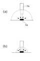
ここで、受光部33と発光部51との距離と受光部に取り込まれる光量の関係を模式図の図8(a)、(b)を用いて説明する。図8(a)は平面状に等方的に光を放射する発光部51aが配置され距離rの位置に受光部33aがある状態を示している。発光部51aから発光された光のうち受光部33aに受光される光は、受光部33aの面積をSaとすると、Sa/4πr2で表される。図8(b)は図8(a)の状態から受光部33aがr/2の距離まで近づいた状態を示している。この場合の受光部33aに到達する光は、Sa/4π(r/2)2で表される。つまり、受光部33aに到達する光は距離rの2乗に逆比例するため、距離が近づくことで光量は大きく増大する。Here, the relationship between the distance between the
以上のとおり、本発明の実施形態によれば、支持部材の一端面を受光部としその部分が空洞部を介して発光部と対向できる構成とすることにより、インクタンクの装着動作によって、受光部を発光部側に近づけることができるように受光部が変位可能となる。これにより、発光部からの光の大部分を受光部に入射させることができ、導光部材など、支持部材とは別個の部材を用いなくても十分な量の光を伝達することが可能となる。 As described above, according to the embodiment of the present invention, the light receiving unit is configured so that the one end surface of the support member can be the light receiving unit and the portion can be opposed to the light emitting unit through the cavity. The light receiving part can be displaced so that the light emitting part can be brought closer to the light emitting part side. As a result, most of the light from the light emitting unit can be incident on the light receiving unit, and a sufficient amount of light can be transmitted without using a member separate from the support member such as a light guide member. Become.
また、発光部と支持部材の受光部とは空洞部を介して配置されるため、インクタンクに不要に加えられた衝撃などによって互いに接触し特に発光部を損傷することを防止できる。 In addition, since the light emitting unit and the light receiving unit of the support member are disposed via the cavity, it is possible to prevent the light emitting unit from being particularly damaged due to contact with each other due to an impact applied to the ink tank unnecessarily.
さらに、支持部材とインクタンクの外装部材とが連結する部分である支持部材の支点部は、上記空洞部を構成する受光部以外の部分であり、その厚みが受光部と比較して薄くされる。これにより、受光部に対応する部分の厚さを所望のものにしつつ、インクタンク装着に伴って支持部材を変位させる力が大きくなることを抑制することができる。 Further, the fulcrum portion of the support member, which is a portion where the support member and the exterior member of the ink tank are connected, is a portion other than the light receiving portion constituting the hollow portion, and the thickness thereof is made thinner than that of the light receiving portion. . Thereby, it is possible to suppress an increase in the force for displacing the support member along with the ink tank mounting, while making the thickness of the portion corresponding to the light receiving portion desired.
なお、上述した例では、特にインクタンクの第1係合部21が設けられたインクタンクについて説明したが、本発明が適用されるインクタンクがこのような構成を必ずしも備える必要がないことはもちろんである。係合部21が無い場合であっても、例えば、インクタンクの装着に際してその背面側の一部がインクタンクホルダなどの装着部と接触し、その接触部分を移動させながら、インクタンクを装着することが可能だからである。 In the above-described example, the ink tank provided with the first engaging
図9は、以上説明したインクタンクを装着して記録を行うインクジェットプリンタ200の本体カバー201を開放した状態を示す斜視図である。 FIG. 9 is a perspective view illustrating a state in which the
図9に示すように、本実施形態のプリンタ200は、記録ヘッドおよびインクタンクを搭載したキャリッジが走査のための移動をして記録を行う機構などプリンタの主要部分を備える。また、本体カバー201およびその他のケース部分によって覆われているプリンタ本体と、その前後にそれぞれ設けられる排紙トレイ203と、自動給紙装置(ASF)202とを備えたものである。また、本体カバーを閉じた状態および開いた状態の両方で本プリンタの状態を表示するための表示器、電源スイッチおよびリセットスイッチを備えた操作部213が設けられている。 As shown in FIG. 9, the
本体カバー201を開放した状態では、図9に示すように、ユーザは、記録ヘッドユニット105およびインクタンク1K、1Y、1M、1Cを搭載したキャリッジ205が移動する範囲およびその周辺を見ることができる。実際は、本体カバー201を開けると、キャリッジ205が自動的に同図に示すほぼ中央の位置(以下、「タンク交換位置」ともいう)へ移動するシーケンスが実行され、ユーザは、このタンク交換位置でそれぞれのインクタンクの交換操作などを行うことができる。 In a state where the
本実施形態のプリンタは、記録ヘッドユニット105に各色のインクに対応したチップ形態の記録ヘッド(不図示)が設けられる。そして、これら各色の記録ヘッドがキャリッジ205の移動によって用紙などの記録媒体に対して走査を行い、この走査の間に記録媒体にインクを吐出して記録を行うものである。すなわち、キャリッジ205は、その移動方向に延在するガイド軸207と摺動可能に係合するとともに、キャリッジモータおよびその駆動力伝達機構によって、上述の移動をすることができる。そして、K、Y、M、Cのインクに対応したそれぞれの記録ヘッドでは、フレキシブルケーブル206を介して本体側の制御回路から送られる吐出データに基づいてインク吐出が行われる。また、紙送りローラや排紙ローラなどの紙送り機構が設けられ、自動給紙装置202から給紙された記録媒体(不図示)を排紙トレイ203まで搬送することができる。また、キャリッジ205には、インクタンクホルダを一体に備えた記録ヘッドユニット105が着脱自在に装着され、一方、この記録ヘッドユニット105に対してそれぞれのインクタンク1がカートリッジの形態にて着脱自在に装着される。すなわち、キャリッジ205に記録ヘッドユニット105を装着し、さらに記録ヘッドユニット105にインクタンク1を装着することが可能であり、本実施形態ではインクタンク1は記録ヘッドユニット105を介してキャリッジ205に着脱可能である。 In the printer of this embodiment, the
記録動作では、記録ヘッドが上記の移動によって走査しその間にそれぞれの記録ヘッドから記録媒体にインクを吐出して記録ヘッドにおける吐出口に対応した幅の領域に記録を行う。これとともに、この走査と次の走査の間に、上記紙送り機構によって上記幅に応じた所定量の紙送りを行うことにより、記録媒体に対して順次記録を行う。また、上記のキャリッジ移動による記録ヘッドの移動範囲の端部には、各記録ヘッドについてその吐出口が配設された面を覆うキャップなどの吐出回復ユニットが設けられている。これにより、記録ヘッドは所定の時間間隔で回復ユニットが設けられた位置へ移動して、予備吐出などの回復処理を行う。 In the recording operation, the recording head scans by the above movement, and during that time, ink is ejected from each recording head to the recording medium, and recording is performed in an area having a width corresponding to the ejection port in the recording head. At the same time, recording is sequentially performed on the recording medium by feeding a predetermined amount of paper according to the width by the paper feeding mechanism between this scanning and the next scanning. In addition, an ejection recovery unit such as a cap is provided at the end of the moving range of the recording head by the carriage movement described above to cover the surface of each recording head on which the ejection port is provided. As a result, the recording head moves to a position where the recovery unit is provided at predetermined time intervals, and performs recovery processing such as preliminary ejection.
各インクタンク1のタンクホルダ部を備えた記録ヘッドユニット105には、前述したように、各インクタンクに対応してコネクタが設けられており、それぞれのコネクタは装着されるインクタンク1に設けられている基板のパッドと接触する。これにより、それぞれの叙述した発光部(LED)の点灯ないし点滅の制御が可能となる。 As described above, the
(第2実施形態)
本発明の第2の実施形態に係るインクタンクは、上述した第1実施形態の、支持部材の一端面である受光部が空洞部を介して発光部と対向できる構成に加え、インクタンクに比較的大きな衝撃が加わったときの支持部材の破損を防ぐための構成を備えたものである。(Second Embodiment)
The ink tank according to the second embodiment of the present invention is compared to the ink tank of the first embodiment described above, in addition to the configuration in which the light receiving portion that is one end surface of the support member can face the light emitting portion through the cavity portion. And a structure for preventing the support member from being damaged when a large impact is applied.
すなわち、第1実施形態で説明した構成のインクタンクは、支持部材の支点から最も遠い部分(以下、開放側端部ともいう)付近に比較的大きな力が加わった場合、支持部材が破損する恐れがある。例えば、インクタンクの重量によっては、落下などした場合に支持部材の開放側端部付近に比較的大きな衝撃が加わることがある。 That is, in the ink tank having the configuration described in the first embodiment, the support member may be damaged when a relatively large force is applied in the vicinity of the portion farthest from the fulcrum of the support member (hereinafter also referred to as an open side end). There is. For example, depending on the weight of the ink tank, a relatively large impact may be applied near the open end of the support member when the ink tank is dropped.
図10(a)〜(d)および図11(a)〜(d)は、第1実施形態で説明したインクタンクが、落下した場合の落下姿勢に応じた支持部材の変位およびその破損を説明する図である。 10 (a) to 10 (d) and FIGS. 11 (a) to 11 (d) illustrate the displacement of the support member according to the drop posture when the ink tank described in the first embodiment falls and the breakage thereof. It is a figure to do.
図10(a)に示す姿勢で、同図の矢印で示す鉛直下方に落下した場合、インクタンク1が面70へ到達すると、支持部材30は、支点34を変位の支点として、支点34近傍の厚みの薄い部分を変形させながらインクタンク本体方向へ変位する。そして、この変位が進むと、図10(b)に示すように、支持部材30の厚みの大きい部分36(以下、導光部36と呼ぶ)が、インクタンク本体に当接する。このとき、支持部材30の開放側端部とインクタンク本体の間には隙間S1が存在する。 In the posture shown in FIG. 10A, when the
落下による衝撃が比較的小さい場合は、支持部材30の図10(a)に示す位置からの変位(変形)と、インクタンク本体と導光部36の当接とによって、支持部材30に作用する衝撃のエネルギーは吸収され、その変位は減衰する。 When the impact due to dropping is relatively small, the
しかし、落下による衝撃が比較的大きくそのエネルギーを全て吸収できない場合は、支持部材30はインクタンク本体と導光部36の接点Y1を支点に、インクタンク本体側へさらに変位する。その変位量は、図10(c)に示すように、最大で支持部材30の開放側端部がインクタンク本体に当接する変位の量である。そして、支持部材の開放側端部がインクタンク本体に当接する状態では、支持部材30の支点34付近は、図10(c)に示すように大きく伸ばされるように変形する。 However, when the impact due to dropping is relatively large and cannot absorb all of the energy, the
ここで、インクタンクの材料は、一般に樹脂が使用されることが多く、樹脂の中でも比較的安価なポリプロピレンが多く用いられる。本実施形態のインクタンクも、容器はポリプロピレンによって形成されており、容器に一体に形成されている支持部材も同様の材料である。そして、ポリプロピレンなどの樹脂は、環境温度が低くなるほど靭性が低下する傾向がある。樹脂の靭性が比較的高い常温環境(25℃程度)では、支持部材30は、図10(c)に示す最大変位位置まで変位しても、靭性のある支持部材30は図10(c)のような状態に撓むことができ、支持部材30が破損する可能性は低い。しかし、樹脂の靭性が低くなる低温環境下では、支持部材30の変形領域である支点34付近は、図10(c)に示すように撓むことができず、その結果、図10(d)に示すように、支点34付近が破損することがある。支持部材30が破損してしまうと、破損の状態によっては記録装置に精度よく装着できなくなり、記録ヘッドへインクを供給できなくなってしまう場合がある。 Here, as a material for the ink tank, a resin is generally used, and a relatively inexpensive polypropylene is often used among the resins. In the ink tank of the present embodiment, the container is made of polypropylene, and the supporting member formed integrally with the container is also made of the same material. And resin, such as a polypropylene, has a tendency for toughness to fall, so that environmental temperature becomes low. In a room temperature environment where the toughness of the resin is relatively high (about 25 ° C.), even if the
図11(a)に示すように、インクタンクが支持部材の変位方向に対して傾いた方向に落下した場合においても同様である。すなわち、インクタンクの支持部材が面70に到達した時点で、支持部材30は、図10(a)に示す方向に落下した場合とほぼ同様に変位し、図11(b)に示すような状態となる。すなわち、支持部材30の開放側端部とインクタンク本体の間には隙間S2が存在する。この場合、落下による衝撃が比較的大きくそのエネルギーを全て吸収できないときは、支持部材30は点Y2を支点にインクタンク本体側へ変位する。そして、支持部材30の面70と接している点Fが力点となり、矢印G方向に力を作用させる。その結果、支持部材30の、接点Y2よりも点F側の部分は、インクタンク本体側へ変位し、接点Y2に関して点F側と反対側の部分は、インクタンク本体から離れる方向へ変位する。つまり、支持部材30は、図11(c)に示すように、点Y2を支点に捩れるような変位をする。この変位によって、接点Y2に関して点F側と反対側の、支持部材30の支点34付近は大きく変形する。そのため、樹脂の靭性が低下する低温環境下では、図11(d)に示すように、支持部材30の厚みの薄い部分である支点34付近が破損することがある。 The same applies when the ink tank drops in a direction inclined with respect to the direction of displacement of the support member, as shown in FIG. That is, when the support member of the ink tank reaches the
以上の通り、第1実施形態にて説明した構成のインクタンクの支持部材に対して比較的大きな衝撃が加わるとそれが破損するおそれがある。特に、収容するインク量を増したインクタンク、つまり重量が比較的重いインクタンクの場合は、支持部材の破損の可能性が高くなる。 As described above, when a relatively large impact is applied to the support member of the ink tank having the configuration described in the first embodiment, it may be damaged. In particular, in the case of an ink tank in which the amount of ink to be stored is increased, that is, an ink tank having a relatively heavy weight, the possibility of damage to the support member is increased.
そこで、本発明の第2の実施形態は、第1実施形態にて説明した構成のインクタンクにおいて、支持部材が変位しその導光部がインクタンク本体と当接した後に、図10(c)や図11(c)に示すような、一部の大きな変形を伴う変位を防ぐための構成を設ける。すなわち、支持部材が必要以上の変位状態とならないように、これを防ぐ規制部材をインクタンクに設ける。 Therefore, in the second embodiment of the present invention, in the ink tank having the configuration described in the first embodiment, after the support member is displaced and the light guide portion contacts the ink tank main body, FIG. Further, a configuration for preventing a displacement accompanied by a large deformation as shown in FIG. 11C is provided. That is, the ink tank is provided with a restricting member for preventing the support member from being displaced more than necessary.
インクタンクにおける支持部材の上述した破損を防止する従来構成として、特許文献3に記載ように、支持部材の近傍において、支持部材の設けられた面に対して支持部材の厚みより高く外方に延在する保護壁を設けるものが知られている。この保護壁によって、例えば、インクタンクの落下などでインクタンクに衝撃が加わった場合でも、支持部材はその厚みより高く外方に延在する保護壁内にあって支持部材に直接衝撃が作用することを防止することができる。 As a conventional configuration for preventing the above-described breakage of the support member in the ink tank, as described in Patent Document 3, in the vicinity of the support member, it extends outwardly higher than the thickness of the support member with respect to the surface on which the support member is provided. There are known ones that provide existing protective walls. For example, even when an impact is applied to the ink tank due to, for example, dropping of the ink tank, the support member is in a protective wall that is higher than its thickness and extends outward, and the impact directly acts on the support member. This can be prevented.
図12(a)および(b)は、本発明の第2の実施形態に係るインクタンクの特に支持部材およびその周囲の構成を示す図であり、特許文献3に記載のような保護壁を設けたインクタンクを示す図である。 12 (a) and 12 (b) are views showing the structure of the support member and its surroundings in particular in the ink tank according to the second embodiment of the present invention. A protective wall as described in Patent Document 3 is provided. FIG.
図12(a)および(b)に示すように、保護壁35は、特許文献3に記載される構成と同様に、支持部材30の近傍であって支持部材の設けられた面に対して支持部材の厚みより高く外方に延在している。すなわち、図12(b)に示すように支持部材30がインクタンク本体側に少なくとも最大に変位したときに、支持部材30の全体が保護壁35内に納まるように保護壁35が外方に延在している。 As shown in FIGS. 12A and 12B, the
このように構成されたインクタンク101は、図13(a)に示すように、図10(a)示した方向に落下した場合でも、平面70とは保護壁35が接触し、支持部材30には、図10(b)に示したように落下による衝撃が直接作用することはない。これにより、図10(c)に示したような支持部材の変位は生じず、支持部材30が破損することはない。 As shown in FIG. 13A, the
また、図11(a)に示した落下の姿勢においても同様に、図13(b)に示すように、平面70とは保護壁35が接触し、図11(b)に示したように、支持部材30に落下による衝撃が直接作用することはない。その結果、図11(c)に示したような、大きな変形を伴う変位を防止することができる。つまり、保護壁35によって、支持部材30が図10(c)や図11(c)に示したように変位することを規制することが可能となるため、支持部材の破損対策となる。 Similarly, in the dropping posture shown in FIG. 11 (a), as shown in FIG. 13 (b), the
(第2実施形態の変形例)
上述の第2実施形態のインクタンク101は、保護壁35によって支持部材30に衝撃力を作用させないことで、支持部材30の変位を間接的に規制している。しかし、この形態に限らず、以下に示すように、規制部材を支持部材30の変位の軌跡上に設け、支持部材30の変位を直接止めることによって規制するようにしても良い。(Modification of the second embodiment)
The
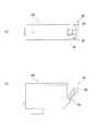
図14(a)および(b)は本変形例に係るインクタンク101の構成を示す図である。これら図に示すように、本変形例のインクタンクは、図10(c)および図11(c)に示したような変位を規制するために、インクタンク101の支持部材30の変位の軌跡上に凸状の規制部38を設けている。詳細には、規制部38は、支持部材30の幅方向における両側の端部付近(2ヶ所)で、支持部材30の開放側端部付近に設けられた、インクタンク本体側に突出した部分である。この規制部38が突出する量は、本例では、図10(b)に示した、支持部材30が導光部材36とケース部材とが接触する変位において、規制部38がインクタンク本体に接する突出量である。なお、突出量はこれに限らない。例えば、規制部38の突出量は、支持部材30が導光部36とインクタンク本体とが接触する変位において、規制部38がインクタンク本体に必ずしも接触していなくてもよい。規制部38とインクタンク本体とが接触したときに、支持部材30が破損に至らない変位量に規制されていればよい。また、規制部38を導光部36よりも突出させて、支持部材30がインクタンク方向に変位したときに導光部36がインクタンク本体に接するより先に、規制部38を接触させる構成でも良い。このように構成した場合、支持部材30の変位による導光部36の他の部材との接触を避けることができるため、導光部36の傷や変形による光量低下を防ぐことができる。ただし、規制部38の高さは、図6(a)に示した、インクタンク1をインクタンクホルダ150へ装着する際の支持部材30の変位を、規制部38によって阻害しないような高さにする必要がある。 FIGS. 14A and 14B are diagrams showing the configuration of the
このように構成されたインクタンク101は、図15(a)に示すように、図10(a)に示した方向に落下した場合に、図10(b)に示した変位において、規制部38とインクタンク本体とが接触する。すなわち、規制部38は支持部材30の開放側端部に設けられているため、規制部38が、他の部材に接触すると、支持部材30はそれ以上変位することはできない。つまり、図10(c)に示した状態へ変位することはできないため、支持部材30が破損する恐れはない。 When the
図11(a)に示した落下姿勢においても同様に、図15(b)に示すように、図11(b)に示す段階において、支持部材30の幅方向における端部付近の2ヶ所に設けられた規制部38によって、図11(c)に示した大きな変形を伴う変位を防止できる。 Similarly, in the dropping posture shown in FIG. 11A, as shown in FIG. 15B, at the stage shown in FIG. 11B, it is provided at two locations near the end in the width direction of the
以上のように、規制部38を設け支持部材30の変位を規制することにより、支持部材30の変形領域にかかるような変位を防止することができ、これにより、落下などの衝撃による支持部材30の破損を防止できる。 As described above, by providing the restricting
なお、規制部38は、本例では、支持部材30に設けているが、例えば、図16(a)および(b)に示すようにケース部材20に設けても良く、また、図17(a)および(b)に示すようにフタ部材10に設けても良い。すなわち、この場合、図16(c)、(d)および図17(c)、(d)に示すように、支持部材30が所定の変位量に達したときに、支持部材の開放端部付近の幅方向における端部付近が規制部38に接するように設ける。その結果、規制部38を、支持部材30に設けた場合と同様の効果を得ることができる。 In this example, the restricting
さらに、本例の規制部38は、コスト・生産性の観点から、インクタンクを構成する部材と同一の材料で一体に成形されているが、それに限らない。例えば、規制部38の衝撃吸収性を高めるために、インサート成形や二色(二層)成形などの成形方法を用いて、規制部38をゴムなどの弾力性に優れた材料で形成してもよい。また、規制部38を他の部材と同一の材料または異なる材料で別部材として、所定の位置に嵌合や溶着・ねじ込みなどの固定方法で固定しても良い。この場合、規制部38は、他の部材と一体に成形する場合よりも形状を自由に構成することが可能となる。 Furthermore, although the
以上説明した構成によれば、発光部の光を表示部へ効率良く導くとともに、生産性を向上させることが可能である。さらに、収容するインク量を増やした場合でも、規制部38を設けることにより、落下等による支持部材の破損を回避することが可能なインクタンクを提供することが可能となる。 According to the configuration described above, it is possible to efficiently guide the light from the light emitting unit to the display unit and improve productivity. Furthermore, even when the amount of ink to be stored is increased, it is possible to provide an ink tank capable of avoiding damage to the support member due to dropping or the like by providing the restricting
1 101 インクタンク
20 ケース部材
21 第一係合部
22 インク供給口
23 インク収納室
24 多孔質部材収納室
25 連通部
30 支持部材
31 操作部
32 第2係合部
33 受光部
34 支点部
35 保護壁
36 導光部
38 規制部
39 貫通口
50 基板
51 発光部
52 電極パッド
53a、53b 固定部
105 記録ヘッドユニット
106 記録ヘッド
150 インクタンクホルダ
152 コネクタ
155 第1係止部
156 第2係止部
157 電気接点部DESCRIPTION OF
Claims (6)
Translated fromJapaneseインクを収納するためのインク収納室を有するケース部材と、
発光部と、
前記ケース部材に支持され、前記ホルダへの前記インクタンクの装着に伴って変位する支持部材であって、(A)前記支持部材の変位によって前記発光部に近づくように前記発光部から離間して配置され、前記発光部からの光を受光する受光部と、(B)表示部と、(C)前記受光部で受光した光を前記表示部に導くことができる導光部と、を有する支持部材と、
を具え、
前記受光部は、前記支持部材に設けられた貫通部の内壁面の一部を構成し、離間している前記発光部からの光を受光するように構成されていることを特徴とするインクタンク。An ink tank that can be attached to and detached from a holder provided in an inkjet printer,
And the case member having an inkstorage chamber forstoringink,
A light emitting unit;
It is supported by the case member,asupport member which is displaced along with the mounting of the ink tank totheholder,at a distance from the light emitting portion closer to the light emitting portion by displacement of(A) thesupport memberA support having a light receiving portion that is disposed and receiveslight from the light emitting portion, (B) a display portion, and (C) a light guide portion that can guide light received by the light receiving portion to the display portion. Members,
With
An ink tank, wherein the light receiving portion constitutes a part of an inner wall surface of a penetrating portion provided in the support member, and is configured to receive light from the light emitting portions that are separated from each other. .
ホルダと、
前記ホルダに着脱可能なインクタンクであって、インクを収納するためのインク収納室を有するケース部材と、発光部と、前記ケース部材に支持され、前記ホルダへの前記インクタンクの装着に伴って変位する支持部材であって、(A)前記支持部材の変位によって前記発光部に近づくように前記発光部から離間して配置され、前記発光部からの光を受光する受光部と、(B)表示部と、(C)前記受光部で受光した光を前記表示部に導くことができる導光部と、を有する支持部材と、を具え、前記受光部は、前記支持部材に設けられた貫通部の内壁面の一部を構成し、離間している前記発光部からの光を受光するように構成されているインクタンクと、
を具えたことを特徴とするインクジェット記録装置。An ink jet recording apparatus that uses a recording head for discharging ink and performs recording by discharging ink from the recording head,
A holder,
An ink tank detachable on the holder,and the case member having an inkstorage chamber forstoring theink, and the light emitting portion,is supported by the case member, with the mounting of the ink tank tothe holder Asupporting member that is displaced; (A)a light receiving unitthat is disposed away from the light emitting unit so as to approach the light emitting unit due to the displacement of thesupporting member,andthat receives light from the light emitting unit; and (B) A support member having a display unit, and (C) a light guide unit capable of guiding light received by the light receiving unit to the display unit ,wherein the light receiving unit is a through-hole provided in the support member. An ink tankconfigured to receive a light from the light emitting unit that is spaced apart from a part of the inner wall surface of the unit ;
An ink jet recording apparatus comprising:
Priority Applications (1)
| Application Number | Priority Date | Filing Date | Title |
|---|---|---|---|
| JP2008197769AJP5300364B2 (en) | 2008-03-31 | 2008-07-31 | Ink tank and ink jet recording apparatus |
Applications Claiming Priority (3)
| Application Number | Priority Date | Filing Date | Title |
|---|---|---|---|
| JP2008092167 | 2008-03-31 | ||
| JP2008092167 | 2008-03-31 | ||
| JP2008197769AJP5300364B2 (en) | 2008-03-31 | 2008-07-31 | Ink tank and ink jet recording apparatus |
Related Child Applications (1)
| Application Number | Title | Priority Date | Filing Date |
|---|---|---|---|
| JP2013095852ADivisionJP5501506B2 (en) | 2008-03-31 | 2013-04-30 | Ink tank |
Publications (2)
| Publication Number | Publication Date |
|---|---|
| JP2009262525A JP2009262525A (en) | 2009-11-12 |
| JP5300364B2true JP5300364B2 (en) | 2013-09-25 |
Family
ID=41154181
Family Applications (2)
| Application Number | Title | Priority Date | Filing Date |
|---|---|---|---|
| JP2008197769AExpired - Fee RelatedJP5300364B2 (en) | 2008-03-31 | 2008-07-31 | Ink tank and ink jet recording apparatus |
| JP2013095852AExpired - Fee RelatedJP5501506B2 (en) | 2008-03-31 | 2013-04-30 | Ink tank |
Family Applications After (1)
| Application Number | Title | Priority Date | Filing Date |
|---|---|---|---|
| JP2013095852AExpired - Fee RelatedJP5501506B2 (en) | 2008-03-31 | 2013-04-30 | Ink tank |
Country Status (3)
| Country | Link |
|---|---|
| JP (2) | JP5300364B2 (en) |
| CN (1) | CN101549586B (en) |
| RU (1) | RU2415020C2 (en) |
Families Citing this family (7)
| Publication number | Priority date | Publication date | Assignee | Title |
|---|---|---|---|---|
| CN105172380B (en)* | 2011-03-30 | 2017-04-12 | 兄弟工业株式会社 | Print cartridge and recording equipment |
| JP6028425B2 (en)* | 2012-07-06 | 2016-11-16 | セイコーエプソン株式会社 | Cartridge and printing device |
| JP6028424B2 (en)* | 2012-07-06 | 2016-11-16 | セイコーエプソン株式会社 | Printing material supply system and cartridge thereof |
| EP3019338B8 (en) | 2013-07-10 | 2019-06-26 | Hewlett-Packard Development Company, L.P. | Fluid container parts including a latch handle and rib |
| JP6281342B2 (en)* | 2014-03-17 | 2018-02-21 | セイコーエプソン株式会社 | Liquid supply unit |
| JP6402985B2 (en)* | 2014-09-08 | 2018-10-10 | セイコーエプソン株式会社 | Liquid injection system |
| JP6409946B2 (en)* | 2017-11-28 | 2018-10-24 | セイコーエプソン株式会社 | Liquid supply unit |
Family Cites Families (7)
| Publication number | Priority date | Publication date | Assignee | Title |
|---|---|---|---|---|
| JPH09210019A (en)* | 1996-01-31 | 1997-08-12 | Mitsumi Electric Co Ltd | Locking device |
| JP2002120377A (en)* | 2000-10-16 | 2002-04-23 | Canon Inc | Ink tank, tank holder |
| JP3793216B2 (en)* | 2003-12-26 | 2006-07-05 | キヤノン株式会社 | Liquid storage container, liquid supply system including the container, method for manufacturing the container, circuit board for the container, and liquid storage cartridge |
| JP4533125B2 (en)* | 2004-10-20 | 2010-09-01 | キヤノン株式会社 | Ink tank and ink jet recording apparatus |
| JP4125279B2 (en)* | 2004-10-20 | 2008-07-30 | キヤノン株式会社 | INK TANK, INKJET RECORDING APPARATUS PROVIDED WITH A HOLDER MOUNTING THE INK TANK AND INKJET RECORDING SYSTEM PROVIDED WITH INK TANK AND HOLDER |
| JP4898147B2 (en)* | 2005-06-01 | 2012-03-14 | キヤノン株式会社 | Ink tank |
| JP4420460B2 (en)* | 2005-06-24 | 2010-02-24 | キヤノン株式会社 | Ink tank substrate unit, ink tank comprising the substrate unit, and ink jet recording apparatus |
- 2008
- 2008-07-31JPJP2008197769Apatent/JP5300364B2/ennot_activeExpired - Fee Related
- 2009
- 2009-03-30RURU2009111714/12Apatent/RU2415020C2/enactive
- 2009-03-31CNCN2009101325387Apatent/CN101549586B/ennot_activeExpired - Fee Related
- 2013
- 2013-04-30JPJP2013095852Apatent/JP5501506B2/ennot_activeExpired - Fee Related
Also Published As
| Publication number | Publication date |
|---|---|
| CN101549586B (en) | 2011-06-01 |
| JP2013144467A (en) | 2013-07-25 |
| CN101549586A (en) | 2009-10-07 |
| RU2009111714A (en) | 2010-10-10 |
| JP5501506B2 (en) | 2014-05-21 |
| RU2415020C2 (en) | 2011-03-27 |
| JP2009262525A (en) | 2009-11-12 |
Similar Documents
| Publication | Publication Date | Title |
|---|---|---|
| JP5501506B2 (en) | Ink tank | |
| JP5258659B2 (en) | Ink tank and inkjet recording system | |
| JP5442142B2 (en) | Ink tank and ink jet recording apparatus | |
| JP4298629B2 (en) | Inkjet recording device | |
| JP4058436B2 (en) | Ink storage container | |
| JP5874160B2 (en) | Holder for detachable liquid container | |
| CN106626789A (en) | Liquid ejecting device and head part | |
| JP5247875B2 (en) | Ink tank and ink jet recording apparatus | |
| JP2006116786A (en) | Liquid storage container and holder for the container | |
| JP2014196000A (en) | Holder capable of attaching and detaching liquid storage container and liquid storage container | |
| JP6025337B2 (en) | Ink tank | |
| JP2006123438A (en) | Ink cartridge and ink jet recording apparatus equipped with the ink cartridge | |
| JP2006181724A (en) | Liquid container, liquid supply system and recording apparatus using the container, circuit module and substrate for container, and liquid container | |
| JP2007185836A (en) | Ink tank | |
| JP2006181723A (en) | Liquid container, liquid supply system and recording apparatus using the container, circuit module and substrate for container, and liquid container |
Legal Events
| Date | Code | Title | Description |
|---|---|---|---|
| RD02 | Notification of acceptance of power of attorney | Free format text:JAPANESE INTERMEDIATE CODE: A7422 Effective date:20101106 | |
| A621 | Written request for application examination | Free format text:JAPANESE INTERMEDIATE CODE: A621 Effective date:20110801 | |
| A131 | Notification of reasons for refusal | Free format text:JAPANESE INTERMEDIATE CODE: A131 Effective date:20130226 | |
| A977 | Report on retrieval | Free format text:JAPANESE INTERMEDIATE CODE: A971007 Effective date:20130228 | |
| A521 | Request for written amendment filed | Free format text:JAPANESE INTERMEDIATE CODE: A523 Effective date:20130430 | |
| TRDD | Decision of grant or rejection written | ||
| A01 | Written decision to grant a patent or to grant a registration (utility model) | Free format text:JAPANESE INTERMEDIATE CODE: A01 Effective date:20130521 | |
| A61 | First payment of annual fees (during grant procedure) | Free format text:JAPANESE INTERMEDIATE CODE: A61 Effective date:20130618 | |
| R151 | Written notification of patent or utility model registration | Ref document number:5300364 Country of ref document:JP Free format text:JAPANESE INTERMEDIATE CODE: R151 | |
| LAPS | Cancellation because of no payment of annual fees |