JP5299149B2 - Wireless communication apparatus and wireless communication system - Google Patents
Wireless communication apparatus and wireless communication systemDownload PDFInfo
- Publication number
- JP5299149B2 JP5299149B2JP2009177379AJP2009177379AJP5299149B2JP 5299149 B2JP5299149 B2JP 5299149B2JP 2009177379 AJP2009177379 AJP 2009177379AJP 2009177379 AJP2009177379 AJP 2009177379AJP 5299149 B2JP5299149 B2JP 5299149B2
- Authority
- JP
- Japan
- Prior art keywords
- wireless communication
- esn
- identification information
- communication device
- unit
- Prior art date
- Legal status (The legal status is an assumption and is not a legal conclusion. Google has not performed a legal analysis and makes no representation as to the accuracy of the status listed.)
- Active
Links
Images


Landscapes
- Mobile Radio Communication Systems (AREA)
Abstract
Description
Translated fromJapanese本発明は、無線通信装置及び無線通信システムに関する。 The present invention relates to a wireless communication apparatus and a wireless communication system.
無線通信には、いわゆるレピータを経由して無線機どうしの通信を行う方法がある。さらに、複数のレピータをネットワークで接続して、複数のレピータのカバーエリアからなる無線通信システムの通信エリアを構成することができる。 Wireless communication includes a method in which wireless devices communicate with each other via a so-called repeater. Furthermore, it is possible to configure a communication area of a wireless communication system that includes a plurality of repeater cover areas by connecting a plurality of repeaters via a network.
このような無線通信システムにおいて、いずれの無線機による通信が行われているかを識別するため、無線機から送信するメッセージ情報とともにその無線機の識別情報を送信する技術が提案されている(例えば特許文献1)。 In such a wireless communication system, in order to identify which wireless device is performing communication, a technique for transmitting identification information of the wireless device together with message information transmitted from the wireless device has been proposed (for example, a patent). Reference 1).
しかし、特許文献1に記載された技術では、無線機を特定するための識別情報をユーザが予め設定する必要があった。また、このような識別情報は、グループが異なったり、使用する地域が異なると同一の識別情報が使用可能となる場合があり、必ずしも無線機を一意に特定することができるとは限らなかった。 However, in the technique described in Patent Document 1, it is necessary for a user to set identification information for specifying a wireless device in advance. Further, in such identification information, the same identification information may be usable if the group is different or the area to be used is different, and the radio device cannot always be uniquely identified.
本発明は、上記実情に鑑みてなされたものであり、通信を行う機器を好適に識別できる無線通信装置及び無線通信システムを提供することを目的とする。 The present invention has been made in view of the above circumstances, and an object of the present invention is to provide a wireless communication apparatus and a wireless communication system that can appropriately identify a device that performs communication.
上記目的を達成するため、本発明の第1の観点に係る無線通信装置は、
無線通信により他の機器と通信を行う無線通信装置であって、
前記無線通信装置に固有の識別情報であるESN(Electric Serial Number)を記憶する識別情報記憶手段と、
通信データを前記他の機器に送信する送信手段と、
前記送信手段が送信する前記通信データに前記識別情報記憶手段が記憶する前記ESNを付加する識別情報付加手段と、
前記通信データを受信したときに当該通信データから前記ESNを抽出する抽出手段と、
前記抽出手段が抽出した前記ESNを外部に送信する手段と、
を備えることを特徴とする。In order to achieve the above object, a wireless communication apparatus according to the first aspect of the present invention provides:
A wireless communication device that communicates with other devices by wireless communication,
Identification information storage means for storing ESN (Electric Serial Number) which is identification information unique to the wireless communication device;
Transmitting means for transmitting communication data to the other device;
Identification information addition means for adding the ESN stored in the identification information storage means to the communication data transmitted by the transmission means;
Extracting means for extracting the ESN from the communication data when the communication data is received;
Means for transmitting the ESN extracted by the extraction means to the outside;
It is characterized by providing.
前記識別情報付加手段は、前記通信データに前記ESNを付加するときに、当該ESNが付加されていることを示す情報をさらに付加するように構成されてもよい。 The identification information adding unit may be configured to further add information indicating that the ESN is added when the ESN is added to the communication data.
本発明の第2の観点に係る無線通信システムは、
無線通信により他の機器と通信を行う無線通信装置と、
前記無線通信装置による通信を中継する中継装置と、
複数の前記中継装置とネットワークを介して接続され、前記無線通信装置及び前記中継装置における通信を統制するためのサーバと、
から構成される無線通信システムであって、
前記無線通信装置は、
前記無線通信装置に固有の識別情報であるESN(Electric Serial Number)を記憶する識別情報記憶手段と、
通信データを前記他の機器に送信する送信手段と、
前記送信手段が送信する前記通信データに前記識別情報記憶手段が記憶する前記ESNを付加する識別情報付加手段と、
前記通信データを受信したときに当該通信データから前記ESNを抽出する抽出手段と、
前記抽出手段が抽出した前記ESNを外部に送信する手段と、
を備えることを特徴とする。A wireless communication system according to a second aspect of the present invention is:
A wireless communication device that communicates with other devices by wireless communication ;
A relay device that relays communication by the wireless communication device;
A plurality of relay devices connected via a network, and a server for controlling communication in the wireless communication device and the relay device;
A wireless communication system comprising:
The wireless communication device
Identification information storage means for storing ESN (Electric Serial Number) which is identification information unique to the wireless communication device;
Transmitting means for transmitting communication data to the other device;
Identification information addition means for adding the ESN stored in the identification information storage means to the communication data transmitted by the transmission means;
Extracting means for extracting the ESN from the communication data when the communication data is received;
Means for transmitting the ESN extracted by the extraction means to the outside;
It is characterized by providing.
本発明によれば、通信を行う機器を好適に識別できる。 ADVANTAGE OF THE INVENTION According to this invention, the apparatus which communicates can be identified suitably.
本発明に係る無線通信装置及び無線通信システムの一実施の形態について、図を参照して説明する。図1は、本発明の一実施の形態に係る無線通信システムの構成例を示す。 An embodiment of a wireless communication apparatus and a wireless communication system according to the present invention will be described with reference to the drawings. FIG. 1 shows a configuration example of a wireless communication system according to an embodiment of the present invention.
無線通信システム5は、例えば図1に示すように、ネットワーク4に接続されている複数のレピータ2(2A、2B、2C、2D)を備える。無線通信システム5には、複数の無線通信装置3(3A、3B、3C、3D、3E、3F)がある。また、ネットワーク4にサーバ1が接続している。また、無線通信装置3の通信情報を管理するための管理用のPC(パーソナルコンピュータ)6(6A、6B)が設けられる。 The
ネットワーク4は、例えば、LAN(Local Area Network)である。ネットワーク4は、その他、回線交換網、パケット交換網、インターネット、専用線網であってもよい。また、ネットワーク4は有線に限らず、例えば無線LANなどの無線通信網でもよい。 The network 4 is, for example, a LAN (Local Area Network). The network 4 may be a circuit switching network, a packet switching network, the Internet, or a dedicated line network. Further, the network 4 is not limited to a wired line, and may be a wireless communication network such as a wireless LAN.
無線通信システム5では、無線通信装置3どうしの通信はレピータ2を介して行われる。例えば、図1の無線通信装置3Aと3Cは、レピータ2Aを介して通信を行う。また、無線通信システム5では、異なるレピータ2の通信範囲(レピータエリア)に属する無線通信装置3どうしの通信は、ネットワーク4を経由して行われる。例えば、無線通信装置3Aと3Dは、レピータ2A、ネットワーク4及びレピータ2Cを経由して通信を行う。ここでの通信には、音声通信やデータ通信が含まれる。 In the
無線通信装置(以下、子機と略称する)3A〜3Fは、レピータ2A〜2Dと無線で通信する。子機3A〜3Fからレピータ2A〜2Dへの通信をアップリンク、レピータ2から子機3への送信をダウンリンクという。アップリンクとダウンリンクは、例えば、異なる周波数で同時に送信される。アップリンクとダウンリンクは、時間分割で2重に送信されてもよい。 Wireless communication devices (hereinafter abbreviated as slave units) 3A to 3F communicate wirelessly with repeaters 2A to 2D. Communication from slave units 3A to 3F to repeaters 2A to 2D is referred to as uplink, and transmission from repeater 2 to slave unit 3 is referred to as downlink. The uplink and downlink are transmitted simultaneously on different frequencies, for example. The uplink and downlink may be transmitted twice in a time division manner.
1つのレピータ2において、アップリンクとダウンリンクを1組として同時に通信できるチャネル数は1又は2以上である。同時通信チャネル数は、レピータ2の構成による。なお、子機3A〜3Fは、図1では移動局のように記載されているが、固定局の場合を含む。 In one repeater 2, the number of channels that can be simultaneously communicated with the uplink and the downlink as one set is 1 or 2 or more. The number of simultaneous communication channels depends on the configuration of the repeater 2. In addition, although the subunit | mobile_unit 3A-3F is described like the mobile station in FIG. 1, the case of a fixed station is included.
この実施の形態の無線通信システム5では、無線通信装置3のうち予め定められたものを管理用の無線通信装置3としている。たとえは、無線通信システム5を構成する無線通信装置3をグループ分けし、そのグループの管理者が持つ無線通信装置3を管理用の無線通信装置3とする。管理用の無線通信装置3は、通信フレームを受信すると、その通信フレームを送信した無線通信装置3を識別する情報を抽出し、管理用のPC6に出力する。 In the
管理用のPC6の記憶部には、各無線通信装置3とその無線通信装置3を識別する情報(後述するESN)とが対応付けて記憶される。管理用のPC6は、無線通信装置3から送出される識別情報に基づき、無線通信装置3の不正使用がないかを監視する。例えば、識別情報が未登録の無線通信装置3による通信が行われていないかなどを監視する。 The storage unit of the management PC 6 stores each wireless communication device 3 and information (ESN to be described later) for identifying the wireless communication device 3 in association with each other. The management PC 6 monitors whether the wireless communication device 3 is illegally used based on the identification information transmitted from the wireless communication device 3. For example, it is monitored whether or not communication is performed by the wireless communication device 3 whose identification information is not registered.
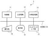
図2は、本発明の一実施の形態に係る無線通信システム5におけるサーバ1の構成例を示すブロック図である。サーバ1は、無線通信システム5における通信全体を統制する。例えば、ユーザがサーバ1を操作することで、レピータ2を遠隔操作し、レピータ2の設定を変更することができる。サーバ1は、図2に示すように、制御部11、主記憶部12、外部記憶部13、操作部15、表示部16及びネットワークインタフェース(以下、ネットワークI/F)部17を備える。主記憶部12、外部記憶部13、操作部15、表示部16及びネットワークI/F部17はいずれも内部バス10を介して制御部11に接続されている。 FIG. 2 is a block diagram showing a configuration example of the server 1 in the
制御部11はCPU(Central Processing Unit)等から構成され、外部記憶部13に記憶されているプログラムに従って、サーバ1の動作を制御する。 The
主記憶部12はRAM(Random-Access Memory)等から構成され、外部記憶部13に記憶されているプログラムをロードし、制御部11の作業領域として用いられる。 The
外部記憶部13は、フラッシュメモリ、ハードディスク、DVD−RAM(Digital Versatile Disc Random-Access Memory)、DVD−RW(Digital Versatile Disc ReWritable)等の不揮発性メモリから構成され、前記の処理を制御部11に行わせるためのプログラムを予め記憶し、また、制御部11の指示に従って、このプログラムが記憶するデータを制御部11に供給し、制御部11から供給されたデータを記憶する。 The
操作部15はキーボード及びマウスなどのポインティングデバイス等と、キーボード及びポインティングデバイス等を内部バスに接続するインタフェース装置から構成されている。操作部15に対する操作情報は制御部11に供給される。 The
表示部16は、CRT(Cathode Ray Tube)又はLCD(Liquid Crystal Display)などから構成され、ネットワーク4上の通信情報などを表示する。 The
ネットワークI/F部17は、無線送受信機、無線モデム又は網終端装置、及びそれらと接続するシリアルインタフェース又はLANインタフェースから構成されている。サーバ1は、ネットワークI/F部17を介して、ネットワーク4に接続する。また、ネットワークI/F部17を介して、子機3やレピータ2を統制するための制御信号を送信する。 The network I /
図3は、本発明の一実施の形態に係る無線通信装置3の構成を示すブロック図である。無線通信装置3は、送信機能と受信機能を備える。受信機能はレピータ2がダウンリンクで送信した信号を受信する。送信機能は、レピータ2にアップリンクで信号を送信する。図3に示すように、無線通信装置3は、アンテナ31と、送受信切替部32と、送信部33と、受信部34と、音声A/D・D/A(アナログ/デジタル・デジタル/アナログ)変換部35と、コントローラ36と、増幅器37と、マイク38と、スピーカ39と、表示部41と、操作部42と、を備える。 FIG. 3 is a block diagram showing a configuration of radio communication apparatus 3 according to the embodiment of the present invention. The wireless communication device 3 has a transmission function and a reception function. The reception function receives a signal transmitted by the repeater 2 on the downlink. The transmission function transmits a signal to the repeater 2 through the uplink. As shown in FIG. 3, the wireless communication device 3 includes an
アンテナ31は、通信相手となる他の無線通信装置3から送信され、レピータ2で中継された信号波を受信する。また、アンテナ31は、他の無線通信装置3から直接送信された信号波を受信する。アンテナ31は、通信相手となる他の無線通信装置3に信号波を中継するレピータ2に向けて信号波を送信する。また、アンテナ31は、他の無線通信装置3に向けて信号波を直接送信する。 The
送受信切替部32は、送信部33から入力された送信用の信号波をアンテナ31に出力する。また、送受信切替部32は、アンテナ31で受信された信号波を入力し、この信号波を受信部34に出力する。 The transmission /
送信部33は、例えば4値FSK(Frequency Shift Keying)変調方式に基づいて、入力された音声信号およびデータ信号を変調し、送受信切替部32に出力する。なお、音声信号は、音声A/D・D/A変換部35から供給され、データ信号は、コントローラ36から供給される。 The
受信部34は、特定の周波数(通信チャンネル)の信号を選択して受信するチューニング機能を備え、コントローラ36の制御に基づいて、受信する無線信号の周波数が設定される。また、受信部34は、入力された受信信号を復調する復調機能を備える。ここでは、受信部34は、送信部33と同様の変調方式に基づいて復調を行う。 The receiving
音声A/D・D/A変換部35は、音声信号をアナログ信号とデジタル信号間で信号変換を行うアナログ−デジタル変換機能を備える。 The audio A / D / D /
コントローラ36は、この無線通信装置3の動作の制御を行う。コントローラ36は、CPU(中央処理装置)36a、ROM(読み出し専用メモリ)36b、RAM(読み書き可能メモリ)36cを備える。 The
ROM36bは、コントローラ36が無線通信装置3の動作を制御するための制御プログラムを格納する。CPU36aは、この制御プログラムに基づいて、無線通信装置3が送信機および受信機として機能するよう制御する。RAM36cは、CPU6aのワークエリアとして機能する。 The ROM 36 b stores a control program for the
また、ROM36bは、ESN(Electronic Serial Number)を記憶する。ESNは、無線通信装置3の製造メーカなどが設定する無線通信装置3に固有の識別情報である。ESNにより、無線通信装置3を特定することができる。このESNは、無線通信装置3のユーザが設定するまでもなく、無線通信装置3が持つ識別情報である。コントローラ36は、通話を行う際の音声データに、このESNを自動的に付加して送信する。 The ROM 36b stores an ESN (Electronic Serial Number). The ESN is identification information unique to the wireless communication device 3 set by the manufacturer of the wireless communication device 3 or the like. The wireless communication device 3 can be specified by the ESN. This ESN is identification information that the wireless communication apparatus 3 has without being set by the user of the wireless communication apparatus 3. The
コントローラ36は、送信部33が、音声信号を出力するとき(通信相手への接続要求を送信するとき)、音声信号に送信先に関する情報や自己のESNを付加する。また、コントローラ36は、受信した通信フレームからESNを抽出する。 When the
増幅器37は、マイク38から供給された音声信号を増幅し、音声A/D・D/A変換部35に供給する。また、増幅器37は、音声A/D・D/A変換部35から供給された音声信号を増幅して、スピーカ39に供給する。 The
マイク38は、ユーザの通話音を取得し、音声信号として増幅器37に供給する。 The
スピーカ39は、増幅器37から供給された音声信号に基づき、通信相手の通話音を出力する。 The
表示部41は、液晶ディスプレイ等からなるモニタ画面を備えて構成される。モニタ画面には、ユーザに対する無線通信装置3の動作状態の報知や、ユーザに対する操作部42による入力を促すメッセージ等が表示される。 The display unit 41 includes a monitor screen made up of a liquid crystal display or the like. On the monitor screen, a notification of the operation state of the wireless communication device 3 to the user, a message prompting the user to input by the
操作部42は、無線通信装置3の動作に関する条件情報を入力するための装置である。操作部42には各種の操作キーが設けられており、ユーザが操作キーを操作して各種の入力を行うことにより、その入力に基づく動作を無線通信装置3に行わせることができる。操作部42に対する操作の内容は、コントローラ36により検出される。即ち、コントローラ36は、操作された操作キーの種類や、操作キーに対する操作の内容を検出する。そして、コントローラ36は、操作キーによって入力された内容を判別し、入力された内容に応じた動作を行うように、無線通信装置3を制御する。 The
この実施の形態の無線通信装置3により音声通信を行うときに送信される通信フレームのフレーム構成について説明する。無線通信装置3のユーザが通話を行うため、操作部42を操作して宛先を指定するとともに、マイク38から音声を入力すると、図4(A)に示すような通信フレームがレピータ2に送信される。 A frame configuration of a communication frame transmitted when voice communication is performed by the wireless communication apparatus 3 according to this embodiment will be described. When the user of the wireless communication apparatus 3 performs a call, the
図4(A)に示すように、無線通信装置3から送信される通信フレームは、プリアンブル、ヘッダ、FACCH(高速付随制御チャンネル)、音声データ、から構成される。 As shown in FIG. 4A, the communication frame transmitted from the wireless communication device 3 includes a preamble, a header, a FACCH (high-speed associated control channel), and audio data.
プリアンブルは、同期をとるためのビット列であり、フレームの始まりを示す制御信号となる。ヘッダは、通話の相手先の識別情報を含む。音声データは、マイク38から入力された音声に対応した音声データである。 The preamble is a bit string for synchronization and is a control signal indicating the start of a frame. The header includes identification information of a call partner. The sound data is sound data corresponding to the sound input from the
FACCHは、音声データに付随して制御情報を送信するために使用されるチャンネルである。この実施の形態では、このFACCHにESNを挿入する。 The FACCH is a channel used for transmitting control information accompanying voice data. In this embodiment, ESN is inserted into this FACCH.
FACCHは、図4(B)に示すように、10オクテットのデータであり、メッセージタイプ、製造番号、ESNコード、モデル番号、バージョン番号、シリアル番号、から構成される。 As shown in FIG. 4B, the FACCH is data of 10 octets and includes a message type, a manufacturing number, an ESN code, a model number, a version number, and a serial number.
メッセージタイプ及び製造番号は、CAI(Common Air Interface)で定められた識別情報である。 The message type and serial number are identification information defined by CAI (Common Air Interface).
第3オクテット以降は、製造メーカが自由に設定できる領域である。この実施の形態では、モデル番号、バージョン番号、及びシリアル番号からなるESNと、ESNコードと、が挿入される。 The third and subsequent octets are areas that can be freely set by the manufacturer. In this embodiment, an ESN including a model number, a version number, and a serial number, and an ESN code are inserted.
ESNコードは、第4オクテット以降にESNが挿入されているか否かを示すコードである。ESNコードには、0x01または0x02の値が設定される。この実施の形態では、ESNコードが0x01であれば第4オクテット以降にESNが挿入されていることを示し、ESNコードが0x02であれば別のデータが挿入されていることを示す。 The ESN code is a code indicating whether an ESN is inserted after the fourth octet. A value of 0x01 or 0x02 is set in the ESN code. In this embodiment, if the ESN code is 0x01, it indicates that the ESN is inserted after the fourth octet, and if the ESN code is 0x02, it indicates that another data is inserted.
この実施の形態では、ESNとして、モデル番号、バージョン番号、シリアル番号が含まれる。モデル番号は、無線通信装置3のモデルを識別するための番号である。バージョン番号は、無線通信装置3のモデルのバージョンを識別するための情報である。シリアル番号は、無線通信装置3そのものを識別するための情報であり一意なデータである。 In this embodiment, the ESN includes a model number, a version number, and a serial number. The model number is a number for identifying the model of the wireless communication device 3. The version number is information for identifying the model version of the wireless communication device 3. The serial number is information for identifying the wireless communication device 3 itself, and is unique data.
このように構成される通信フレームが、レピータ2に中継され、ネットワーク4を介して他の無線通信装置3に伝送され、他の無線通信装置3との通話が可能になる。 The communication frame configured as described above is relayed to the repeater 2 and transmitted to the other wireless communication device 3 via the network 4 so that a call with the other wireless communication device 3 becomes possible.
通信フレームを受信した無線通信装置3(例えば、無線通信装置3のうち予め定められた管理用の無線通信装置3)のコントローラ36は、受信した通信フレームからESNを抽出する。通信フレームからESNを抽出する際には、まずFACCHにおけるESNコードを抽出し、ESNコードが0x01であれば第4オクテット以降にESNが挿入されていると判別して、第4オクテット以降(図4(B)の例では、第4〜第9オクテット)のESNデータを抽出する。 The
管理用の無線通信装置3のコントローラ36は、ESNを抽出すると、管理用の無線通信装置3の通信可能範囲内に設置された管理用のPC6にESNを送出する。例えば、管理用の無線通信装置3のコントローラ36が抽出したESNを管理用のPC6にクローン出力する。管理用の無線通信装置3を通信ケーブルで直接PC6に接続するようにして、その通信ケーブルを介して送出されるようしてもよい。なお、管理用の無線通信装置3からPC6へのESNの送出は、管理用の無線通信装置3が通信フレームを受信するたびに行うようにしてもよいし、予め定められた周期ごとに行うようにしてもよい。また、管理用の無線通信装置3において、所定の操作がなされたときに送出するようにしてもよい。 When the
ESNを受信したPC6は、例えば、ESNから特定される無線通信装置3の内容を表示部に表示する。PC6の管理者は、ESNから特定される無線通信装置3の情報を監視できる。ここで、特定の無線通信装置3に不正使用が見つかった場合、その無線通信装置3に対して(またはそのユーザに対して)、警告や注意を送信することができる。また、管理用の無線通信装置3を制御する信号を送信して、その無線通信装置3の使用を不可能にすることができる。 PC6 which received ESN displays the content of the radio | wireless communication apparatus 3 specified from ESN on a display part, for example. The administrator of the PC 6 can monitor the information of the wireless communication device 3 specified from the ESN. Here, when unauthorized use is found in a specific wireless communication device 3, a warning or caution can be transmitted to the wireless communication device 3 (or to the user). In addition, a signal for controlling the management wireless communication device 3 can be transmitted to disable the use of the wireless communication device 3.
例えば、複数種類のうち特定のグループ(例えば、A社)が使用するトーンが予め決まっており、例えばA社の無線通信装置3が送信した通信フレームは、A社の無線通信装置3のみで受信するようになっている場合、A社の管理用の無線通信装置3が通信フレームを受信すると、ESNを抽出する。そして、抽出したESNは、PC6に送出される。管理用のPC6には、A社が使用する無線通信装置3のESNを予め登録しておく。管理用のPC6に登録されていないESNを受信した場合、そのESNを対応する無線通信装置3は不正使用されている(A社の社員になりすましている)と判断できる。 For example, a tone used by a specific group (for example, Company A) among a plurality of types is determined in advance. For example, a communication frame transmitted by the wireless communication device 3 of Company A is received only by the wireless communication device 3 of Company A. If the wireless communication apparatus 3 for management of company A receives the communication frame, the ESN is extracted. Then, the extracted ESN is sent to the PC 6. In the management PC 6, the ESN of the wireless communication device 3 used by the company A is registered in advance. When an ESN that is not registered in the management PC 6 is received, it can be determined that the wireless communication device 3 corresponding to the ESN has been illegally used (spoofed as an employee of company A).
以上説明したように、この実施の形態の無線通信装置3は、無線通信装置3を一意に識別できる識別情報であるESNは通信データに自動的に付加して送信する。これにより、通信を行っている無線通信装置3を好適に識別できる。また、ESNは予め定められた識別情報であるので、ユーザが特段の設定をするまでもなく、無線通信装置3を識別できる。 As described above, the wireless communication apparatus 3 of this embodiment automatically adds ESN, which is identification information that can uniquely identify the wireless communication apparatus 3, to the communication data and transmits it. Thereby, the wireless communication apparatus 3 that is performing communication can be suitably identified. Since ESN is predetermined identification information, the wireless communication device 3 can be identified without the user having to make special settings.
なお、上記実施の形態で説明したハードウエア構成、通信フレームのフレーム構成や、動作は一例であり、任意に変形及び修正が可能である。例えば、サーバ1は専用のシステムによらず、通常のコンピュータを用いて実現可能である。例えば、前記の動作を実行するためのコンピュータプログラムを、コンピュータが読みとり可能な記録媒体(フレキシブルディスク、CD−ROM、DVD−ROM等)に格納して配布し、当該コンピュータプログラムをコンピュータにインストールすることにより、前記の処理を実行するサーバ1を構成してもよい。また、インターネット等の通信ネットワーク上のサーバ装置が有する記憶装置に当該コンピュータプログラムを格納しておき、通常のコンピュータシステムがダウンロード等することでサーバ1を構成してもよい。 Note that the hardware configuration, the frame configuration of the communication frame, and the operations described in the above embodiment are examples, and can be arbitrarily modified and modified. For example, the server 1 can be realized using a normal computer without using a dedicated system. For example, a computer program for executing the above operation is stored and distributed in a computer-readable recording medium (flexible disk, CD-ROM, DVD-ROM, etc.), and the computer program is installed in the computer. Thus, the server 1 that executes the above-described processing may be configured. Further, the server 1 may be configured by storing the computer program in a storage device of a server device on a communication network such as the Internet and downloading it by a normal computer system.
また、サーバ1の機能を、OS(オペレーティングシステム)とアプリケーションプログラムの分担、またはOSとアプリケーションプログラムとの協働により実現する場合などには、アプリケーションプログラム部分のみを記録媒体や記憶装置に格納してもよい。 Further, when the functions of the server 1 are realized by sharing of an OS (operating system) and an application program, or by cooperation between the OS and the application program, only the application program portion is stored in a recording medium or a storage device. Also good.
また、搬送波にコンピュータプログラムを重畳し、通信ネットワークを介して配信することも可能である。たとえば、通信ネットワーク上の掲示板(BBS, Bulletin Board System)に前記コンピュータプログラムを掲示し、ネットワークを介して前記コンピュータプログラムを配信してもよい。そして、このコンピュータプログラムを起動し、OSの制御下で、他のアプリケーションプログラムと同様に実行することにより、前記の処理を実行できるように構成してもよい。 It is also possible to superimpose a computer program on a carrier wave and distribute it via a communication network. For example, the computer program may be posted on a bulletin board (BBS, Bulletin Board System) on a communication network, and the computer program distributed via the network. The computer program may be started and executed in the same manner as other application programs under the control of the OS, so that the above-described processing may be executed.
また、上記実施の形態では、無線通信装置3により音声通信を行う場合の通信フレームにESNを挿入する例について説明したが、データ通信時にも同様に通信フレームに自動的にESNを挿入して送信することができる。 In the above embodiment, the example in which the ESN is inserted into the communication frame when voice communication is performed by the wireless communication device 3 has been described. However, the ESN is automatically inserted into the communication frame and transmitted in the same manner during data communication. can do.
また、無線通信装置3が信号を送受信するための信号の変調方式として4値FSK変調方式を採用する例を説明したが、他の変調方式を採用してもよい。例えば、信号の変調方式として、GMSK(Gaussian filtered Minimum Shift Keying)変調方式やQPSK(Quadrature Phase Shift Keying)変調方式やその他の変調方式を採用してもよい。 Moreover, although the example which employ | adopts 4 value FSK modulation system as a signal modulation system for the radio | wireless communication apparatus 3 to transmit / receive a signal was demonstrated, you may employ | adopt another modulation system. For example, as a signal modulation method, a GMSK (Gaussian filtered Minimum Shift Keying) modulation method, a QPSK (Quadrature Phase Shift Keying) modulation method, or another modulation method may be employed.
また、上記実施の形態では、管理用の無線通信装置3が通信フレームからESNを抽出して、管理用の無線通信装置3以外の無線通信装置3が通信フレームにESNを挿入することを説明したが、管理用とそれ以外の無線通信装置3の機能は同一であり、管理用以外の無線通信装置3でもPCに通信ケーブルを接続することなどにより、通信フレームから抽出したESNを出力することができる。また、管理用の無線通信装置3が音声通話やデータ通信を行う場合に、送信する通信フレームにESNを自動的に挿入することもできる。 In the above-described embodiment, the management wireless communication device 3 extracts the ESN from the communication frame, and the wireless communication devices 3 other than the management wireless communication device 3 insert the ESN into the communication frame. However, the functions of the wireless communication device 3 for management and other wireless communication devices 3 are the same, and the wireless communication device 3 other than for management can output the ESN extracted from the communication frame by connecting a communication cable to the PC. it can. Further, when the management wireless communication apparatus 3 performs a voice call or data communication, an ESN can be automatically inserted into a communication frame to be transmitted.
1 サーバ
2、2A、2B、2C、2D レピータ
3、3A、3B、3C、3D、3E、3F 無線通信装置
4 ネットワーク
5 無線通信システム
6 PC
10 内部バス
11 制御部
12 主記憶部
13 外部記憶部
15 操作部
16 表示部
17 ネットワークインタフェース部
31 アンテナ
32 送受信切替部
33 送信部
34 受信部
35 音声A/D・D/A変換部
36 コントローラ
37 増幅器
38 マイク
39 スピーカ
41 表示部
42 操作部1
10
Claims (3)
Translated fromJapanese前記無線通信装置に固有の識別情報であるESN(Electric Serial Number)を記憶する識別情報記憶手段と、
通信データを前記他の機器に送信する送信手段と、
前記送信手段が送信する前記通信データに前記識別情報記憶手段が記憶する前記ESNを付加する識別情報付加手段と、
前記通信データを受信したときに当該通信データから前記ESNを抽出する抽出手段と、
前記抽出手段が抽出した前記ESNを外部に送信する手段と、
を備えることを特徴とする無線通信装置。A wireless communication device that communicates with other devices by wireless communication,
Identification information storage means for storing ESN (Electric Serial Number) which is identification information unique to the wireless communication device;
Transmitting means for transmitting communication data to the other device;
Identification information addition means for adding the ESN stored in the identification information storage means to the communication data transmitted by the transmission means;
Extracting means for extracting the ESN from the communication data when the communication data is received;
Means for transmitting the ESN extracted by the extraction means to the outside;
A wireless communication apparatus comprising:
前記無線通信装置による通信を中継する中継装置と、
複数の前記中継装置とネットワークを介して接続され、前記無線通信装置及び前記中継装置における通信を統制するためのサーバと、
から構成される無線通信システムであって、
前記無線通信装置は、
前記無線通信装置に固有の識別情報であるESN(Electric Serial Number)を記憶する識別情報記憶手段と、
通信データを前記他の機器に送信する送信手段と、
前記送信手段が送信する前記通信データに前記識別情報記憶手段が記憶する前記ESNを付加する識別情報付加手段と、
前記通信データを受信したときに当該通信データから前記ESNを抽出する抽出手段と、
前記抽出手段が抽出した前記ESNを外部に送信する手段と、
を備えることを特徴とする無線通信システム。A wireless communication device that communicates with other devices by wireless communication ;
A relay device that relays communication by the wireless communication device;
A plurality of relay devices connected via a network, and a server for controlling communication in the wireless communication device and the relay device;
A wireless communication system comprising:
The wireless communication device
Identification information storage means for storing ESN (Electric Serial Number) which is identification information unique to the wireless communication device;
Transmitting means for transmitting communication data to the other device;
Identification information addition means for adding the ESN stored in the identification information storage means to the communication data transmitted by the transmission means;
Extracting means for extracting the ESN from the communication data when the communication data is received;
It means for transmittingthe ESNprevious SL extracting means has extracted to theoutside,
A wireless communication system comprising:
Priority Applications (1)
| Application Number | Priority Date | Filing Date | Title |
|---|---|---|---|
| JP2009177379AJP5299149B2 (en) | 2009-07-30 | 2009-07-30 | Wireless communication apparatus and wireless communication system |
Applications Claiming Priority (1)
| Application Number | Priority Date | Filing Date | Title |
|---|---|---|---|
| JP2009177379AJP5299149B2 (en) | 2009-07-30 | 2009-07-30 | Wireless communication apparatus and wireless communication system |
Publications (2)
| Publication Number | Publication Date |
|---|---|
| JP2011035497A JP2011035497A (en) | 2011-02-17 |
| JP5299149B2true JP5299149B2 (en) | 2013-09-25 |
Family
ID=43764164
Family Applications (1)
| Application Number | Title | Priority Date | Filing Date |
|---|---|---|---|
| JP2009177379AActiveJP5299149B2 (en) | 2009-07-30 | 2009-07-30 | Wireless communication apparatus and wireless communication system |
Country Status (1)
| Country | Link |
|---|---|
| JP (1) | JP5299149B2 (en) |
Cited By (1)
| Publication number | Priority date | Publication date | Assignee | Title |
|---|---|---|---|---|
| US8713771B2 (en) | 2010-02-04 | 2014-05-06 | Delphi Technologies, Inc. | Procedure and device for assembly of a flexible seal element on an electrical conductor |
Families Citing this family (1)
| Publication number | Priority date | Publication date | Assignee | Title |
|---|---|---|---|---|
| CN103379483B (en)* | 2012-04-16 | 2017-06-06 | 中兴通讯股份有限公司 | A kind of method of information of mobile terminal safety management, device and mobile terminal |
Family Cites Families (4)
| Publication number | Priority date | Publication date | Assignee | Title |
|---|---|---|---|---|
| US5546444A (en)* | 1994-03-11 | 1996-08-13 | Bellsouth Corporation | Methods and apparatus for communicating data via a cellular network control channel |
| EP1478138A2 (en)* | 2003-05-13 | 2004-11-17 | Samsung Electronics Co., Ltd. | Security method for broadcasting service in a mobile communication system |
| US7688854B2 (en)* | 2003-10-03 | 2010-03-30 | Nokia Corporation | Generalized spare extension field usage in frame protocol data frame |
| US20070099638A1 (en)* | 2005-10-28 | 2007-05-03 | Voltz Christopher D | Multi-number wireless communications system and method |
- 2009
- 2009-07-30JPJP2009177379Apatent/JP5299149B2/enactiveActive
Cited By (1)
| Publication number | Priority date | Publication date | Assignee | Title |
|---|---|---|---|---|
| US8713771B2 (en) | 2010-02-04 | 2014-05-06 | Delphi Technologies, Inc. | Procedure and device for assembly of a flexible seal element on an electrical conductor |
Also Published As
| Publication number | Publication date |
|---|---|
| JP2011035497A (en) | 2011-02-17 |
Similar Documents
| Publication | Publication Date | Title |
|---|---|---|
| WO2010050535A1 (en) | Wireless communication system, wireless communication method, relay device, and wireless terminal device | |
| JP2007214713A (en) | Wireless lan system, access point and channel control method and program for use therein | |
| US9166672B2 (en) | Wireless communication system, relay system, repeater devices and synchronization method | |
| US20190104422A1 (en) | System and Method for Easy Configuration and Authentication of Network Devices | |
| US8824957B2 (en) | Wireless communication system, wireless communication method, wireless communication terminal device, relay device, and relay system | |
| JP4929815B2 (en) | Wireless communication system and automatic channel switching method | |
| EP2341734B1 (en) | Wireless communication system, wireless communication method thereof and wireless terminal device | |
| JP5194996B2 (en) | Repeater, repeater control method, radio communication system, and repeater control program | |
| JP2007295135A (en) | Radio communication apparatus, repeater, and radio communication system | |
| JP5299149B2 (en) | Wireless communication apparatus and wireless communication system | |
| JP4935168B2 (en) | Communication system and communication control method | |
| JP2010136349A (en) | Relay system, relay device and synchronization method | |
| CN103987073A (en) | Control method based on wireless protocol extension | |
| JP4876933B2 (en) | Wireless communication system, control method therefor, and server | |
| US20170318412A1 (en) | Method for transmitting data between two subscribers | |
| EP2341750B1 (en) | Relay device, wireless communication method, and wireless communication system | |
| JP5499884B2 (en) | Wireless communication device, repeater, and wireless communication system | |
| JP4671798B2 (en) | Communication equipment | |
| JP2015053662A (en) | Method of setting wireless relay device | |
| KR20090130744A (en) | Remote management method and system of wireless communication terminal | |
| JP4562522B2 (en) | COMMUNICATION DEVICE AND COMMUNICATION METHOD | |
| JP5299148B2 (en) | COMMUNICATION DEVICE, COMMUNICATION SYSTEM, AND PROGRAM | |
| JP6330453B2 (en) | Image recording apparatus, recording system, and program | |
| JP2018125888A (en) | Image recording device, recording system, and program | |
| JP2010193009A (en) | Communication system and communication control program |
Legal Events
| Date | Code | Title | Description |
|---|---|---|---|
| A621 | Written request for application examination | Free format text:JAPANESE INTERMEDIATE CODE: A621 Effective date:20120410 | |
| A977 | Report on retrieval | Free format text:JAPANESE INTERMEDIATE CODE: A971007 Effective date:20130225 | |
| A131 | Notification of reasons for refusal | Free format text:JAPANESE INTERMEDIATE CODE: A131 Effective date:20130305 | |
| A521 | Request for written amendment filed | Free format text:JAPANESE INTERMEDIATE CODE: A523 Effective date:20130430 | |
| TRDD | Decision of grant or rejection written | ||
| A01 | Written decision to grant a patent or to grant a registration (utility model) | Free format text:JAPANESE INTERMEDIATE CODE: A01 Effective date:20130521 | |
| A61 | First payment of annual fees (during grant procedure) | Free format text:JAPANESE INTERMEDIATE CODE: A61 Effective date:20130603 | |
| R150 | Certificate of patent or registration of utility model | Free format text:JAPANESE INTERMEDIATE CODE: R150 Ref document number:5299149 Country of ref document:JP Free format text:JAPANESE INTERMEDIATE CODE: R150 | |
| R250 | Receipt of annual fees | Free format text:JAPANESE INTERMEDIATE CODE: R250 | |
| R250 | Receipt of annual fees | Free format text:JAPANESE INTERMEDIATE CODE: R250 | |
| R250 | Receipt of annual fees | Free format text:JAPANESE INTERMEDIATE CODE: R250 | |
| R250 | Receipt of annual fees | Free format text:JAPANESE INTERMEDIATE CODE: R250 | |
| R250 | Receipt of annual fees | Free format text:JAPANESE INTERMEDIATE CODE: R250 | |
| R250 | Receipt of annual fees | Free format text:JAPANESE INTERMEDIATE CODE: R250 | |
| R250 | Receipt of annual fees | Free format text:JAPANESE INTERMEDIATE CODE: R250 | |
| R250 | Receipt of annual fees | Free format text:JAPANESE INTERMEDIATE CODE: R250 | |
| R250 | Receipt of annual fees | Free format text:JAPANESE INTERMEDIATE CODE: R250 | |
| R250 | Receipt of annual fees | Free format text:JAPANESE INTERMEDIATE CODE: R250 |