JP5294554B2 - GAME PROGRAM, GAME DEVICE, GAME SYSTEM, AND GAME PROCESSING METHOD - Google Patents
GAME PROGRAM, GAME DEVICE, GAME SYSTEM, AND GAME PROCESSING METHODDownload PDFInfo
- Publication number
- JP5294554B2 JP5294554B2JP2006310617AJP2006310617AJP5294554B2JP 5294554 B2JP5294554 B2JP 5294554B2JP 2006310617 AJP2006310617 AJP 2006310617AJP 2006310617 AJP2006310617 AJP 2006310617AJP 5294554 B2JP5294554 B2JP 5294554B2
- Authority
- JP
- Japan
- Prior art keywords
- moving object
- game
- point
- virtual camera
- virtual
- Prior art date
- Legal status (The legal status is an assumption and is not a legal conclusion. Google has not performed a legal analysis and makes no representation as to the accuracy of the status listed.)
- Active
Links
Images


Classifications
- A63F13/10—
- A—HUMAN NECESSITIES
- A63—SPORTS; GAMES; AMUSEMENTS
- A63F—CARD, BOARD, OR ROULETTE GAMES; INDOOR GAMES USING SMALL MOVING PLAYING BODIES; VIDEO GAMES; GAMES NOT OTHERWISE PROVIDED FOR
- A63F13/00—Video games, i.e. games using an electronically generated display having two or more dimensions
- A63F13/50—Controlling the output signals based on the game progress
- A63F13/52—Controlling the output signals based on the game progress involving aspects of the displayed game scene
- A63F13/525—Changing parameters of virtual cameras
- A63F13/5258—Changing parameters of virtual cameras by dynamically adapting the position of the virtual camera to keep a game object or game character in its viewing frustum, e.g. for tracking a character or a ball
- A—HUMAN NECESSITIES
- A63—SPORTS; GAMES; AMUSEMENTS
- A63F—CARD, BOARD, OR ROULETTE GAMES; INDOOR GAMES USING SMALL MOVING PLAYING BODIES; VIDEO GAMES; GAMES NOT OTHERWISE PROVIDED FOR
- A63F13/00—Video games, i.e. games using an electronically generated display having two or more dimensions
- A63F13/45—Controlling the progress of the video game
- A—HUMAN NECESSITIES
- A63—SPORTS; GAMES; AMUSEMENTS
- A63F—CARD, BOARD, OR ROULETTE GAMES; INDOOR GAMES USING SMALL MOVING PLAYING BODIES; VIDEO GAMES; GAMES NOT OTHERWISE PROVIDED FOR
- A63F13/00—Video games, i.e. games using an electronically generated display having two or more dimensions
- A63F13/80—Special adaptations for executing a specific game genre or game mode
- A63F13/812—Ball games, e.g. soccer or baseball
- A—HUMAN NECESSITIES
- A63—SPORTS; GAMES; AMUSEMENTS
- A63F—CARD, BOARD, OR ROULETTE GAMES; INDOOR GAMES USING SMALL MOVING PLAYING BODIES; VIDEO GAMES; GAMES NOT OTHERWISE PROVIDED FOR
- A63F2300/00—Features of games using an electronically generated display having two or more dimensions, e.g. on a television screen, showing representations related to the game
- A63F2300/60—Methods for processing data by generating or executing the game program
- A63F2300/66—Methods for processing data by generating or executing the game program for rendering three dimensional images
- A63F2300/6661—Methods for processing data by generating or executing the game program for rendering three dimensional images for changing the position of the virtual camera
- A63F2300/6684—Methods for processing data by generating or executing the game program for rendering three dimensional images for changing the position of the virtual camera by dynamically adapting its position to keep a game object in its viewing frustrum, e.g. for tracking a character or a ball
- A—HUMAN NECESSITIES
- A63—SPORTS; GAMES; AMUSEMENTS
- A63F—CARD, BOARD, OR ROULETTE GAMES; INDOOR GAMES USING SMALL MOVING PLAYING BODIES; VIDEO GAMES; GAMES NOT OTHERWISE PROVIDED FOR
- A63F2300/00—Features of games using an electronically generated display having two or more dimensions, e.g. on a television screen, showing representations related to the game
- A63F2300/80—Features of games using an electronically generated display having two or more dimensions, e.g. on a television screen, showing representations related to the game specially adapted for executing a specific type of game
- A63F2300/8011—Ball
Landscapes
- Engineering & Computer Science (AREA)
- Multimedia (AREA)
- Processing Or Creating Images (AREA)
Abstract
Description
Translated fromJapanese本発明は、ゲームプログラム、ゲーム装置、ゲームシステムおよびゲーム処理方法に関し、より特定的には、仮想3次元空間内に設定されたフィールドの上方を移動オブジェクトが移動する様子を示すゲーム画像を表示画面上に表示するためのゲームプログラム、ゲーム装置、ゲームシステムおよびゲーム処理方法に関する。The present invention relates to a game program, a game device, a game system, and a game processing method . More specifically, the present invention relates to a display screen for displaying a game image showing a moving object moving above a field set in a virtual three-dimensional space. The present invention relates to a game program, a game device, a game system, and a game processing method for displaying on the screen.
従来、野球ゲームやゴルフゲーム等のように、仮想3次元空間内に設定されたフィールドの上方を移動オブジェクトが移動する様子を示すゲーム画像を表示画面上に表示するゲームプログラムおよびゲーム装置が存在する。 2. Description of the Related Art Conventionally, there are game programs and game devices that display a game image showing a moving object moving above a field set in a virtual three-dimensional space, such as a baseball game and a golf game, on a display screen. .
例えば、2005年7月14日にコナミ株式会社によって発売された「実況パワフルプロ野球12」という名称の野球ゲームでは、打者がボールを打ったときに、上空に位置する仮想カメラがボールの影を追いかけるような仮想カメラの制御方法が採用されている。このような仮想カメラの制御方法によれば、画面にはボールの影の周辺の様子が常に表示されるので、プレイヤは、ボールの予定落下地点に向かって走る野手の動きを眺めることができる。 For example, in a baseball game called “Jikkyou Powerful Pro Baseball 12” released by Konami Co., Ltd. on July 14, 2005, when a batter hits the ball, the virtual camera located in the sky casts the shadow of the ball. A virtual camera control method is used. According to such a control method of the virtual camera, since the state around the shadow of the ball is always displayed on the screen, the player can watch the movement of the fielder running toward the planned drop point of the ball.
野球ゲームに関する別の従来技術として、特許文献1に記載のゲーム装置がある。このゲーム装置では、打者がボールを打った直後に、ボールの予定落下地点に一番早く到達できる野手が選択され、この野手がボールを捕球するまでの間、仮想カメラが常にこの野手の後方からボールを捉えるような仮想カメラの制御方法が採用されている。このような仮想カメラの制御方法によれば、プレイヤは、野手の視点からボールを眺めることができ、現実感のあるゲームプレイが可能となる。
しかしながら、前述の「実況パワフルプロ野球12」に採用されている仮想カメラの制御方法によれば、仮想カメラはボール自体の位置に関係なくボールの影を追いかけるため、ボールの軌道が高い場合にはボールが画面に表示されないという状況が発生する。したがって、プレイヤは、ボールが空高く飛んでいる様子を画面上で確認することができず、臨場感を味わうことができないという問題がある。 However, according to the control method of the virtual camera adopted in the above-mentioned “actual powerful
一方、特許文献1に記載のゲーム装置に採用されている仮想カメラの制御方法によれば、プレイヤは、ボールの予定落下地点に一番早く到達できる野手の動きと、ボールが空高く飛んでいる様子の両方を同時に画面上で確認することができる。しかしながら、ボールの予定落下地点に一番早く到達できる野手の後方から上方を撮影するように仮想カメラが設定されるため、プレイヤは、ボールの真下の地点や予定落下地点等の様子を把握できず、例えば、ボールの予定落下地点に向かって走る他の野手の動きや、ボールがファウルラインの外側を飛んでいるのかファイルラインの内側を飛んでいるのかなどを画面上で確認することができないという問題がある。 On the other hand, according to the control method of the virtual camera employed in the game apparatus described in
それゆえに本発明は、仮想3次元空間内に設定されたフィールドの上方を移動オブジェクトが移動する様子を示すゲーム画像を表示画面上に表示するにあたり、プレイヤに臨場感を与えることができ、なおかつ移動オブジェクトが着地する前にプレイヤが移動オブジェクトの下方の様子を把握できるようなゲーム画像を生成可能なゲームプログラム、ゲーム装置、ゲームシステムおよびゲーム処理方法を提供することを目的とする。Therefore, the present invention can give a player a sense of realism when moving a game image showing a moving object moving above a field set in a virtual three-dimensional space on the display screen, and also move It is an object of the presentinvention to provide a game program, a game device, a game system, and a game processing method capable of generating a game image that allows a player to grasp a state below a moving object before the object lands.
上記目的を達成するために、本発明は以下のように構成される。なお、括弧内の参照符号は、本発明の理解を助けるために図面との対応関係の一例を示したものであって、本発明の範囲を何ら限定するものではない。 In order to achieve the above object, the present invention is configured as follows. The reference numerals in parentheses show an example of the correspondence with the drawings in order to help understanding of the present invention, and do not limit the scope of the present invention.
本発明のゲームプログラム(330)は、仮想3次元空間内に設定されたフィールドの上方を移動オブジェクトが移動する様子を示すゲーム画像を、当該仮想3次元空間内に設定された仮想カメラに基づき表示画面上に表示するゲーム装置(5)のコンピュータ(30)に、移動制御ステップ(S34)、条件判定ステップ(S50)、注視点制御ステップ(S52,S56,S58)、および画像生成ステップを実行させる。移動制御ステップは、フィールドの上方を移動オブジェクトが略放物線状に移動するように、仮想3次元空間における当該移動オブジェクトの位置を示す位置情報(335)を周期的に更新するステップである。条件判定ステップは、移動制御ステップで移動制御される移動オブジェクトの速度(336)が特定条件を満たしたか否かを判定するステップである。注視点制御ステップは、移動オブジェクトの速度が特定条件を満たしていなければ、仮想カメラの注視点を移動オブジェクトの現在位置(P1)とし、移動オブジェクトの速度が特定条件を満たしたことに応じて、仮想カメラの注視点を移動オブジェクトの現在位置からフィールド上の特定地点(P2,P3)へと移動させるステップである。画像生成ステップは、前記注視点制御ステップで制御された前記仮想カメラの注視点に基づいて、前記仮想カメラから見える前記仮想3次元空間を表すゲーム画像を、表示画面上に表示すべきゲーム画像として生成するステップである。The game program (330) of the present invention displays a game image showing a moving object moving above a field set in thevirtual three-dimensional space based on a virtual camera set in the virtual three-dimensional space.the computer (30) of a game apparatus for displaying on a screen(5), the movement control step (S34), the condition determination step (S50), the gazing point controlling step (S52, S56, S58), andperform the image generation step Let The movement control step is a step of periodically updating position information (335) indicating the position of the moving object in the virtual three-dimensional space so that the moving object moves in a substantially parabolic shape above the field. The condition determination step is a step of determining whether or not the speed (336) of the moving object that is movement-controlled in the movement control step satisfies a specific condition. In the gazing point control step, if the speed of the moving object does not satisfy the specific condition, the gazing point of the virtual camera is set as the current position (P1) of the moving object, and the speed of the moving object satisfies the specific condition. In this step, the gazing point of the virtual camera is moved from the current position of the moving object to a specific point (P2, P3) on the field. Image generating step onthebasis of the gaze pointof theprevious SLthe virtual camera that is controlled by fixation point controlstep, a game imagein the game image representing the virtual three-dimensional space viewed from the virtual camera, to be displayed on the display screenIt is a step to generateas .
本発明の変形例として、特定地点は、移動オブジェクトを通る鉛直線とフィールドとが交差する地点(P2)であってもよい。 As a modification of the present invention, the specific point may be a point (P2) where the vertical line passing through the moving object and the field intersect.
さらなる変形例として、特定地点は、移動オブジェクトの予定落下地点(P3)であってもよい。 As a further modification, the specific point may be a scheduled drop point (P3) of the moving object.
さらなる変形例として、特定地点は、移動オブジェクトを通る鉛直線とフィールドとが交差する地点(P2)と、移動オブジェクトの予定落下地点(P3)との中間地点であってもよい。 As a further modification, the specific point may be an intermediate point between a point (P2) where a vertical line passing through the moving object and the field intersect and a planned falling point (P3) of the moving object.
さらなる変形例として、特定条件は、仮想3次元空間における移動オブジェクトの速度の大きさ(√(Vx2+Vy2+Vz2))に関する条件であってもよい。As a further modification, the specific condition may be a condition related to the magnitude of the velocity of the moving object (√ (Vx2 + Vy2 + Vz2 )) in the virtual three-dimensional space.
さらなる変形例として、特定条件は、移動オブジェクトの速度の大きさが減少から増加に転じることであってもよい。これにより、移動オブジェクトが上昇から下降に転じたときに、仮想カメラの注視点を移動オブジェクトの現在位置からフィールド上の特定地点へと移動させることができる。 As a further modification, the specific condition may be that the magnitude of the speed of the moving object changes from decreasing to increasing. As a result, when the moving object turns from ascending to descending, the gazing point of the virtual camera can be moved from the current position of the moving object to a specific point on the field.
さらなる変形例として、特定条件は、仮想3次元空間における移動オブジェクトの速度の重力方向成分(Vy)の向き及び/又は大きさに関する条件であってもよい。 As a further modification, the specific condition may be a condition related to the direction and / or magnitude of the gravity direction component (Vy) of the velocity of the moving object in the virtual three-dimensional space.
さらなる変形例として、特定条件は、移動オブジェクトの速度の重力方向成分の向きが反転することであってもよい。これにより、移動オブジェクトが上昇から下降に転じたときに、仮想カメラの注視点を移動オブジェクトの現在位置からフィールド上の特定地点へと移動させることができる。 As a further modification, the specific condition may be that the direction of the gravity direction component of the speed of the moving object is reversed. As a result, when the moving object turns from ascending to descending, the gazing point of the virtual camera can be moved from the current position of the moving object to a specific point on the field.
さらなる変形例として、注視点制御ステップにおいて、移動オブジェクトの速度が特定条件を満たしたことに応じて、仮想カメラの注視点が移動オブジェクトの現在位置を離れて特定地点へ徐々に近づくように、仮想カメラの注視点の位置が繰り返し更新されてもよい(S58)。 As a further modification, in the point-of-gaze control step, the virtual camera is set so that the point of interest of the virtual camera gradually moves away from the current position of the moving object and gradually approaches the specific point when the speed of the moving object satisfies the specific condition. The position of the gazing point of the camera may be updated repeatedly (S58).
さらなる変形例として、注視点制御ステップにおいて、仮想カメラの注視点は、現在の注視点と特定地点との間の距離に応じた速度で、特定地点へ徐々に近づくように繰り返し更新されてもよい。 As a further modification, in the gazing point control step, the gazing point of the virtual camera may be repeatedly updated so as to gradually approach the specific point at a speed according to the distance between the current gazing point and the specific point. .
さらなる変形例として、注視点制御ステップにおいて、仮想カメラの注視点は、一定の速度で特定地点へ徐々に近づくように繰り返し更新されてもよい。 As a further modification, in the gazing point control step, the gazing point of the virtual camera may be repeatedly updated so as to gradually approach the specific point at a constant speed.
本発明のゲーム装置(5)は、仮想3次元空間内に設定されたフィールドの上方を移動オブジェクトが移動する様子を示すゲーム画像を、当該仮想3次元空間内に設定された仮想カメラに基づき表示画面上に表示するゲーム装置である。このゲーム装置は、移動制御手段(30,S34)、条件判定手段(30,S50)、注視点制御手段(30,S52,S56,S58)、および画像生成手段(30,32)を備える。The game device (5) of the present invention displays a game image showing a moving object moving above a field set in avirtual three-dimensional space based on a virtual camera set in the virtual three-dimensional space. It is a game device displayed on a screen. The game apparatus includes movement control means (30, S34), condition determination means (30, S50), gazing point control means (30, S52, S56, S58), and image generation means (30, 32).
本発明によれば、仮想3次元空間内に設定されたフィールドの上方を移動オブジェクトが移動する様子を示すゲーム画像を表示画面上に表示するにあたり、プレイヤに臨場感を与えることができ、なおかつ移動オブジェクトが着地する前にプレイヤが移動オブジェクトの下方の様子を把握できるようなゲーム画像を生成することが可能となる。 According to the present invention, it is possible to give a player a sense of presence and display a moving image when a game image showing a moving object moving above a field set in a virtual three-dimensional space is displayed on the display screen. It is possible to generate a game image that allows the player to grasp the state below the moving object before the object lands.
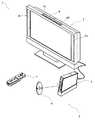
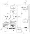
図1を参照して、本発明の一実施形態に係るゲーム装置について説明する。以下、説明を具体的にするために、当該ゲーム装置の一例の据置型のゲーム装置を含むゲームシステムについて説明する。なお、図1は据置型のゲーム装置3を含むゲームシステム1の外観図であり、図2はゲーム装置本体5のブロック図である。以下、当該ゲームシステム1について説明する。 A game device according to an embodiment of the present invention will be described with reference to FIG. In the following, a game system including a stationary game apparatus as an example of the game apparatus will be described in order to make the description more specific. FIG. 1 is an external view of a
図1において、ゲームシステム1は、表示手段の一例の家庭用テレビジョン受像機(以下、モニタと記載する)2と、当該モニタ2に接続コードを介して接続する据置型のゲーム装置3とから構成される。モニタ2は、ゲーム装置本体5から出力された音声信号を音声出力するためのスピーカ2aを備える。また、ゲーム装置3は、本願発明の情報処理プログラムの一例のゲームプログラムを記録した光ディスク4と、当該光ディスク4のゲームプログラムを実行してゲーム画面をモニタ2に表示出力させるためのコンピュータを搭載したゲーム装置本体5と、ゲーム画面に表示されたキャラクタなどの画像などのゲームに必要な操作情報をゲーム装置本体5に与えるためのコントローラ7とを備えている。 In FIG. 1, a
また、ゲーム装置本体5は、通信ユニット6を内蔵する。通信ユニット6は、コントローラ7から無線送信されるデータを受信し、ゲーム装置本体5からコントローラ7へデータを送信して、コントローラ7とゲーム装置本体5とは無線通信によって接続する。さらに、ゲーム装置本体5には、当該ゲーム装置本体5に対して交換可能に用いられる情報記憶媒体の一例の光ディスク4が脱着される。ゲーム装置本体5の前部主面には、当該ゲーム装置本体5の電源ON/OFFスイッチ、ゲーム処理のリセットスイッチ、光ディスク4を脱着する投入口、およびゲーム装置本体5の投入口から光ディスク4を取り出すイジェクトスイッチ等が設けられている。 In addition, the
また、ゲーム装置本体5には、セーブデータ等のデータを固定的に記憶するバックアップメモリとして機能するフラッシュメモリ38が搭載される。ゲーム装置本体5は、光ディスク4に記憶されたゲームプログラム等を実行することによって、その結果をゲーム画像としてモニタ2に表示する。さらに、ゲーム装置本体5は、フラッシュメモリ38に記憶されたセーブデータを用いて、過去に実行されたゲーム状態を再現して、ゲーム画像をモニタ2に表示することもできる。そして、ゲーム装置本体5のプレイヤは、モニタ2に表示されたゲーム画像を見ながら、コントローラ7を操作することによって、ゲーム進行を楽しむことができる。 In addition, the
コントローラ7は、通信ユニット6を内蔵するゲーム装置本体5へ、例えばBluetooth(ブルートゥース;登録商標)の技術を用いて操作情報などの送信データを無線送信する。コントローラ7は、主にモニタ2の表示画面に表示されるゲーム空間に登場するプレイヤキャラクタ等を操作したりするための操作手段である。コントローラ7は、片手で把持可能な程度の大きさのハウジングと、当該ハウジングの表面に露出して設けられた複数個の操作ボタン(十字キーやスティック等を含む)が設けられている。また、後述により明らかとなるが、コントローラ7は、当該コントローラ7から見た画像を撮像する撮像情報演算部74を備えている。また、撮像情報演算部74の撮像対象の一例として、モニタ2の表示画面近傍に2つのLEDモジュール(以下、マーカと記載する)8Lおよび8Rが設置される。これらマーカ8Lおよび8Rは、センサバー8の両端部にそれぞれ設置されており、それぞれモニタ2の前方に向かって例えば赤外光を出力する。また、コントローラ7は、ゲーム装置本体5の通信ユニット6から無線送信された送信データを通信部75で受信して、当該送信データに応じた音や振動を発生させることもできる。 The
図2において、ゲーム装置本体5は、各種プログラムを実行する例えばCPU(セントラルプロセッシングユニット)30を備える。CPU30は、図示しないブートROMに記憶された起動プログラムを実行し、メインメモリ33等のメモリの初期化等を行った後、光ディスク4に記憶されているゲームプログラムの実行し、そのゲームプログラムに応じたゲーム処理等を行うものである。CPU30には、メモリコントローラ31を介して、GPU(Graphics Processing Unit)32、メインメモリ33、DSP(Digital Signal Processor)34、およびARAM(Audio RAM)35などが接続される。また、メモリコントローラ31には、所定のバスを介して、通信ユニット6、ビデオI/F(インターフェース)37、フラッシュメモリ38、オーディオI/F39、およびディスクI/F41が接続され、それぞれのインターフェースにモニタ2、スピーカ2a、およびディスクドライブ40が接続されている。 In FIG. 2, the
GPU32は、CPU30の命令に基づいて画像処理を行うものあり、例えば、3Dグラフィックスの表示に必要な計算処理を行う半導体チップで構成される。GPU32は、図示しない画像処理専用のメモリやメインメモリ33の一部の記憶領域を用いて画像処理を行う。GPU32は、これらを用いてモニタ2に表示すべきゲーム画像データやムービ映像を生成し、適宜メモリコントローラ31およびビデオI/F37を介してモニタ2に出力する。 The
メインメモリ33は、CPU30で使用される記憶領域であって、CPU30の処理に必要なゲームプログラム等を適宜記憶する。例えば、メインメモリ33は、CPU30によって光ディスク4から読み出されたゲームプログラムや各種データ等を記憶する。このメインメモリ33に記憶されたゲームプログラムや各種データ等がCPU30によって実行される。 The
DSP34は、ゲームプログラム実行時にCPU30において生成されるサウンドデータ等を処理するものであり、そのサウンドデータ等を記憶するためのARAM35が接続される。ARAM35は、DSP34が所定の処理(例えば、先読みしておいたゲームプログラムやサウンドデータの記憶)を行う際に用いられる。DSP34は、ARAM35に記憶されたサウンドデータを読み出し、メモリコントローラ31およびオーディオI/F39を介してモニタ2に備えるスピーカ2aに出力させる。 The
メモリコントローラ31は、データ転送を統括的に制御するものであり、上述した各種I/Fが接続される。上述したように通信ユニット6は、コントローラ7からの送信データを受信し、当該送信データをCPU30へ出力する。また、通信ユニット6は、CPU30から出力された送信データをコントローラ7の通信部75へ送信する。ビデオI/F37には、モニタ2が接続される。オーディオI/F39にはモニタ2に内蔵されるスピーカ2aが接続され、DSP34がARAM35から読み出したサウンドデータやディスクドライブ40から直接出力されるサウンドデータをスピーカ2aから出力可能に接続される。ディスクI/F41には、ディスクドライブ40が接続される。ディスクドライブ40は、所定の読み出し位置に配置された光ディスク4に記憶されたデータを読み出し、ゲーム装置本体5のバスやオーディオI/F39に出力する。LED制御部42は、センサバー8に設けられたマーカ8Lおよび8Rの発光制御を行う。 The
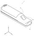
図3および図4を参照して、コントローラ7について説明する。なお、図3は、コントローラ7の上面後方から見た斜視図である。図4は、コントローラ7を下面前方から見た斜視図である。 The
図3および図4において、コントローラ7は、例えばプラスチック成型によって形成されたハウジング71を有しており、当該ハウジング71に複数の操作部72が設けられている。ハウジング71は、その前後方向を長手方向とした略直方体形状を有しており、全体として大人や子供の片手で把持可能な大きさである。 3 and 4, the
ハウジング71上面の中央前面側に、十字キー72aが設けられる。この十字キー72aは、十字型の4方向プッシュスイッチであり、4つの方向(前後左右)に対応する操作部分が十字の突出片にそれぞれ90°間隔で配置される。プレイヤが十字キー72aのいずれかの操作部分を押下することによって前後左右いずれかの方向を選択される。例えばプレイヤが十字キー72aを操作することによって、仮想ゲーム世界に登場するプレイヤキャラクタ等の移動方向を指示したり、複数の選択肢から選択指示したりすることができる。 A cross key 72 a is provided on the center front side of the upper surface of the
なお、十字キー72aは、上述したプレイヤの方向入力操作に応じて操作信号を出力する操作部であるが、他の態様の操作部でもかまわない。例えば、十字方向に4つのプッシュスイッチを配設し、プレイヤによって押下されたプッシュスイッチに応じて操作信号を出力する操作部を設けてもかまわない。さらに、上記4つのプッシュスイッチとは別に、上記十字方向が交わる位置にセンタスイッチを配設し、4つのプッシュスイッチとセンタスイッチとを複合した操作部を設けてもかまわない。また、ハウジング71上面から突出した傾倒可能なスティック(いわゆる、ジョイスティック)を倒すことによって、傾倒方向に応じて操作信号を出力する操作部を上記十字キー72aの代わりに設けてもかまわない。さらに、水平移動可能な円盤状部材をスライドさせることによって、当該スライド方向に応じた操作信号を出力する操作部を、上記十字キー72aの代わりに設けてもかまわない。また、タッチパッドを、上記十字キー72aの代わりに設けてもかまわない。 Note that the cross key 72a is an operation unit that outputs an operation signal in response to the above-described direction input operation of the player, but may be an operation unit of another mode. For example, four push switches may be provided in the cross direction, and an operation unit that outputs an operation signal according to the push switch pressed by the player may be provided. Further, apart from the four push switches, a center switch may be provided at a position where the cross direction intersects, and an operation unit in which the four push switches and the center switch are combined may be provided. An operation unit that outputs an operation signal in accordance with the tilt direction by tilting a tiltable stick (so-called joystick) protruding from the upper surface of the
ハウジング71上面の十字キー72aより後面側に、複数の操作ボタン72b〜72gが設けられる。操作ボタン72b〜72gは、プレイヤがボタン頭部を押下することによって、それぞれの操作ボタン72b〜72gに割り当てられた操作信号を出力する操作部である。例えば、操作ボタン72b〜72dには、1番ボタン、2番ボタン、およびAボタン等としての機能が割り当てられる。また、操作ボタン72e〜72gには、マイナスボタン、ホームボタン、およびプラスボタン等としての機能が割り当てられる。これら操作ボタン72a〜72gは、ゲーム装置本体5が実行するゲームプログラムに応じてそれぞれの操作機能が割り当てられる。なお、図3に示した配置例では、操作ボタン72b〜72dは、ハウジング71上面の中央前後方向に沿って並設されている。また、操作ボタン72e〜72gは、ハウジング71上面の左右方向に沿って操作ボタン72bおよび72dの間に並設されている。そして、操作ボタン72fは、その上面がハウジング71の上面に埋没しており、プレイヤが不意に誤って押下することのないタイプのボタンである。 A plurality of
また、ハウジング71上面の十字キー72aより前面側に、操作ボタン72hが設けられる。操作ボタン72hは、遠隔からゲーム装置本体5の電源をオン/オフする電源スイッチである。この操作ボタン72hも、その上面がハウジング71の上面に埋没しており、プレイヤが不意に誤って押下することのないタイプのボタンである。 An
また、ハウジング71上面の操作ボタン72cより後面側に、複数のLED702が設けられる。ここで、コントローラ7は、他のコントローラ7と区別するためにコントローラ種別(番号)が設けられている。例えば、LED702は、コントローラ7に現在設定されている上記コントローラ種別をプレイヤに通知するために用いられる。具体的には、コントローラ7から通信ユニット6へ送信データを送信する際、上記コントローラ種別に応じて複数のLED702のうち、種別に対応するLEDが点灯する。 A plurality of
また、ハウジング71上面には、操作ボタン72bおよび操作ボタン72e〜72gの間に後述するスピーカ(図5のスピーカ706)からの音を外部に放出するための音抜き孔が形成されている。 Further, on the upper surface of the
一方、ハウジング71下面には、凹部が形成されている。ハウジング71下面の凹部は、プレイヤがコントローラ7の前面をマーカ8Lおよび8Rに向けて片手で把持したときに、当該プレイヤの人差し指や中指が位置するような位置に形成される。そして、上記凹部の後面側傾斜面には、操作ボタン72iが設けられる。操作ボタン72iは、例えばBボタンとして機能する操作部である。 On the other hand, a recess is formed on the lower surface of the
また、ハウジング71前面には、撮像情報演算部74の一部を構成する撮像素子743が設けられる。ここで、撮像情報演算部74は、コントローラ7が撮像した画像データを解析してその中で輝度が高い場所を判別してその場所の重心位置やサイズなどを検出するためのシステムであり、例えば、最大200フレーム/秒程度のサンプリング周期であるため比較的高速なコントローラ7の動きでも追跡して解析することができる。この撮像情報演算部74の詳細な構成については、後述する。また、ハウジング71の後面には、コネクタ73が設けられている。コネクタ73は、例えばエッジコネクタであり、例えば接続ケーブルと嵌合して接続するために利用される。 An
ここで、以下の説明を具体的にするために、コントローラ7に対して設定する座標系について定義する。図3および図4に示すように、互いに直交するXYZ軸をコントローラ7に対して定義する。具体的には、コントローラ7の前後方向となるハウジング71の長手方向をZ軸とし、コントローラ7の前面(撮像情報演算部74が設けられている面)方向をZ軸正方向とする。また、コントローラ7の上下方向をY軸とし、ハウジング71の下面(操作ボタン72iが設けられた面)方向をY軸正方向とする。さらに、コントローラ7の左右方向をX軸とし、ハウジング71の左側面(図3では表されずに図4で表されている側面)方向をX軸正方向とする。 Here, in order to make the following description concrete, a coordinate system set for the
次に、図5および図6を参照して、コントローラ7の内部構造について説明する。なお、図5は、コントローラ7の上筐体(ハウジング71の一部)を外した状態を後面側から見た斜視図である。図6は、コントローラ7の下筐体(ハウジング71の一部)を外した状態を前面側から見た斜視図である。ここで、図6に示す基板700は、図5に示す基板700の裏面から見た斜視図となっている。 Next, the internal structure of the
図5において、ハウジング71の内部には基板700が固設されており、当該基板700の上主面上に操作ボタン72a〜72h、加速度センサ701、LED702、およびアンテナ754等が設けられる。そして、これらは、基板700等に形成された配線(図示せず)によってマイコン751等(図6、図7参照)に接続される。また、無線モジュール753(図7参照)およびアンテナ754によって、コントローラ7がワイヤレスコントローラとして機能する。なお、ハウジング71内部には図示しない水晶振動子703が設けられており、後述するマイコン751の基本クロックを生成する。また、基板700の上主面上に、スピーカ706およびアンプ708が設けられる。また、加速度センサ701は、操作ボタン72dの左側の基板700上(つまり、基板700の中央部ではなく周辺部)に設けられる。したがって、加速度センサ701は、コントローラ7の長手方向を軸とした回転に応じて、重力加速度の方向変化に加え、遠心力による成分の含まれる加速度を検出することができるので、所定の演算により、検出される加速度データからコントローラ7の回転を良好な感度でゲーム装置本体5等が判定することができる。 In FIG. 5, a
一方、図6において、基板700の下主面上の前端縁に撮像情報演算部74が設けられる。撮像情報演算部74は、コントローラ7の前方から順に赤外線フィルタ741、レンズ742、撮像素子743、および画像処理回路744によって構成されており、それぞれ基板700の下主面に取り付けられる。また、基板700の下主面上の後端縁にコネクタ73が取り付けられる。さらに、基板700の下主面上にサウンドIC707およびマイコン751が設けられている。サウンドIC707は、基板700等に形成された配線によってマイコン751およびアンプ708と接続され、ゲーム装置本体5から送信されたサウンドデータに応じてアンプ708を介してスピーカ706に音声信号を出力する。 On the other hand, in FIG. 6, an imaging
そして、基板700の下主面上には、バイブレータ704が取り付けられる。バイブレータ704は、例えば振動モータやソレノイドである。バイブレータ704は、基板700等に形成された配線によってマイコン751と接続され、ゲーム装置本体5から送信された振動データに応じてその作動をオン/オフする。バイブレータ704が作動することによってコントローラ7に振動が発生するので、それを把持しているプレイヤの手にその振動が伝達され、いわゆる振動対応ゲームが実現できる。ここで、バイブレータ704は、ハウジング71のやや前方寄りに配置されるため、プレイヤが把持している状態において、ハウジング71が大きく振動することになり、振動を感じやすくなる。 A
次に、図7を参照して、コントローラ7の内部構成について説明する。なお、図7は、コントローラ7の構成を示すブロック図である。 Next, the internal configuration of the
図7において、コントローラ7は、上述した操作部72、撮像情報演算部74、加速度センサ701、バイブレータ704、スピーカ706、サウンドIC707、およびアンプ708の他に、その内部に通信部75を備えている。 In FIG. 7, the
撮像情報演算部74は、赤外線フィルタ741、レンズ742、撮像素子743、および画像処理回路744を含んでいる。赤外線フィルタ741は、コントローラ7の前方から入射する光から赤外線のみを通過させる。レンズ742は、赤外線フィルタ741を透過した赤外線を集光して撮像素子743へ出射する。撮像素子743は、例えばCMOSセンサやあるいはCCDのような固体撮像素子であり、レンズ742が集光した赤外線を撮像する。したがって、撮像素子743は、赤外線フィルタ741を通過した赤外線だけを撮像して画像データを生成する。撮像素子743で生成された画像データは、画像処理回路744で処理される。具体的には、画像処理回路744は、撮像素子743から得られた画像データを処理して高輝度部分を検知し、それらの位置座標や面積を検出した結果を示す処理結果データを通信部75へ出力する。なお、これらの撮像情報演算部74は、コントローラ7のハウジング71に固設されており、ハウジング71自体の方向を変えることによってその撮像方向を変更することができる。 The imaging
コントローラ7は、3軸(X、Y、Z軸)の加速度センサ701を備えていることが好ましい。この3軸の加速度センサ701は、3方向、すなわち、上下方向(図3に示すY軸)、左右方向(図3に示すX軸)、および前後方向(図3に示すZ軸)で直線加速度を検知する。また、他の実施形態においては、ゲーム処理に用いる制御信号の種類によっては、X軸とY軸(または他の対になった軸)のそれぞれに沿った直線加速度のみを検知する2軸の加速度検出手段を使用してもよい。さらに、他の実施形態においては、ゲーム処理に用いる制御信号の種類によっては、XYZ軸のいずれか1軸に沿った直線加速度のみを検知する1軸の加速度検出手段を使用してもよい。例えば、この3軸、2軸、または1軸の加速度センサ701は、アナログ・デバイセズ株式会社(Analog Devices, Inc.)またはSTマイクロエレクトロニクス社(STMicroelectronics N.V.)から入手可能であるタイプのものでもよい。加速度センサ701は、シリコン微細加工されたMEMS(Micro Electro Mechanical Systems:微小電子機械システム)の技術に基づいた静電容量式(静電容量結合式)であることが好ましい。しかしながら、既存の加速度検出手段の技術(例えば、圧電方式や圧電抵抗方式)あるいは将来開発される他の適切な技術を用いて3軸、2軸、または1軸の加速度センサ701が提供されてもよい。 The
加速度センサ701に用いられるような加速度検出手段は、加速度センサ701の持つ各軸に対応する直線に沿った加速度(直線加速度)のみを検知することができる。つまり、加速度センサ701からの直接の出力は、その1軸、2軸、または3軸のそれぞれに沿った直線加速度(静的または動的)を示す信号である。このため、加速度センサ701は、非直線状(例えば、円弧状)の経路に沿った動き、回転、回転運動、角変位、傾斜、位置、または姿勢等の物理特性を直接検知することはできない。 The acceleration detecting means used in the
しかしながら、加速度センサ701から出力される加速度の信号に対して追加の処理を行うことによって、コントローラ7に関するさらなる情報を推測または算出(判定)することができることは、当業者であれば本明細書の説明から容易に理解できるであろう。例えば、静的な加速度(重力加速度)が検知されると、加速度センサ701からの出力を用いて、傾斜角度と検知された加速度とを用いた演算によって重力ベクトルに対する対象(コントローラ7)の傾きを判定することができる。このように、加速度センサ701をマイコン751(またはゲーム装置本体5に含まれるCPU30等の他のプロセッサ)と組み合わせて用いることによって、コントローラ7の傾き、姿勢、または位置を判定することができる。同様に、加速度センサ701を備えるコントローラ7がプレイヤの手で動的に加速されて動かされる場合に、加速度センサ701によって生成される加速度信号を処理することによって、コントローラ7の様々な動きおよび/または位置を算出することができる。他の実施例では、加速度センサ701は、信号をマイコン751に出力する前に内蔵の加速度検出手段から出力される加速度信号に対して所望の処理を行うための、組込み式の信号処理装置または他の種類の専用の処理装置を備えていてもよい。例えば、組込み式または専用の処理装置は、加速度センサ701が静的な加速度(例えば、重力加速度)を検出するためのものである場合、検知された加速度信号をそれに相当する傾斜角(あるいは、他の好ましいパラメータ)に変換するものであってもよい。加速度センサ701でそれぞれ検知された加速度を示すデータは通信部75に出力される。 However, it is understood by those skilled in the art that additional information regarding the
他の実施形態の例では、コントローラ7の動きを検出する動きセンサとして、回転素子または振動素子などを内蔵したジャイロセンサを用いてもよい。この実施形態で使用されるMEMSジャイロセンサの一例として、アナログ・デバイセズ株式会社から入手可能なものがある。加速度センサ701と異なり、ジャイロセンサは、それが内蔵する少なくとも一つのジャイロ素子の軸を中心とした回転(または角速度)を直接検知することができる。このように、ジャイロセンサと加速度センサとは基本的に異なるので、個々の用途のためにいずれの装置が選択されるかによって、これらの装置からの出力信号に対して行う処理を適宜変更する必要がある。 In an example of another embodiment, a gyro sensor incorporating a rotation element or a vibration element may be used as a motion sensor that detects the movement of the
具体的には、加速度センサの代わりにジャイロセンサを用いて傾きや姿勢を算出する場合には、大幅な変更を行う。すなわち、ジャイロセンサを用いる場合、検出開始の状態において傾きの値を初期化する。そして、当該ジャイロセンサから出力される角速度データを積分する。次に、初期化された傾きの値からの傾きの変化量を算出する。この場合、算出される傾きは、角度に対応する値が算出されることになる。一方、加速度センサによって傾きを算出する場合には、重力加速度のそれぞれの軸に関する成分の値を、所定の基準と比較することによって傾きを算出するので、算出される傾きはベクトルで表すことが可能であり、初期化を行わずとも、加速度検出手段を用いて検出される絶対的な方向を検出することが可能である。また、傾きとして算出される値の性質は、ジャイロセンサが用いられる場合には角度であるのに対して、加速度センサが用いられる場合にはベクトルであるという違いがある。したがって、加速度センサに代えてジャイロセンサが用いられる場合、当該傾きのデータに対して、2つのデバイスの違いを考慮した所定の変換を行う必要がある。加速度検出手段とジャイロスコープとの基本的な差異と同様にジャイロスコープの特性は当業者に公知であるので、本明細書ではさらなる詳細を省略する。ジャイロセンサは、回転を直接検知できることによる利点を有する一方、一般的には、加速度センサは、本実施形態で用いるようなコントローラに適用される場合、ジャイロセンサに比べて費用効率が良いという利点を有する。 Specifically, when the inclination or posture is calculated using a gyro sensor instead of the acceleration sensor, a significant change is made. That is, when the gyro sensor is used, the inclination value is initialized in the detection start state. Then, the angular velocity data output from the gyro sensor is integrated. Next, a change amount of the inclination from the initialized inclination value is calculated. In this case, the calculated inclination is a value corresponding to the angle. On the other hand, when the inclination is calculated by the acceleration sensor, the inclination is calculated by comparing the value of the component relating to each axis of the gravitational acceleration with a predetermined reference, so the calculated inclination can be expressed by a vector. Thus, it is possible to detect the absolute direction detected using the acceleration detecting means without performing initialization. In addition, the property of the value calculated as the inclination is an angle when a gyro sensor is used, but a vector when an acceleration sensor is used. Therefore, when a gyro sensor is used instead of the acceleration sensor, it is necessary to perform predetermined conversion in consideration of the difference between the two devices with respect to the tilt data. Since the characteristics of the gyroscope as well as the basic differences between the acceleration detection means and the gyroscope are known to those skilled in the art, further details are omitted here. While the gyro sensor has the advantage of being able to directly detect rotation, in general, the acceleration sensor has the advantage of being more cost effective than the gyro sensor when applied to a controller as used in this embodiment. Have.
通信部75は、マイクロコンピュータ(Micro Computer:マイコン)751、メモリ752、無線モジュール753、およびアンテナ754を含んでいる。マイコン751は、処理の際にメモリ752を記憶領域として用いながら、送信データを無線送信する無線モジュール753を制御する。また、マイコン751は、アンテナ754を介して無線モジュール753が受信したゲーム装置本体5からのデータに応じて、サウンドIC707およびバイブレータ704の動作を制御する。サウンドIC707は、通信部75を介してゲーム装置本体5から送信されたサウンドデータ等を処理する。また、マイコン751は、通信部75を介してゲーム装置本体5から送信された振動データ(例えば、バイブレータ704をONまたはOFFする信号)等に応じて、バイブレータ704を作動させる。 The
コントローラ7に設けられた操作部72からの操作信号(キーデータ)、加速度センサ701からの3軸方向の加速度信号(X、Y、およびZ軸方向加速度データ)、および撮像情報演算部74からの処理結果データは、マイコン751に出力される。マイコン751は、入力した各データ(キーデータ、X、Y、およびZ軸方向加速度データ、処理結果データ)を通信ユニット6へ送信する送信データとして一時的にメモリ752に格納する。ここで、通信部75から通信ユニット6への無線送信は、所定の周期毎に行われるが、ゲームの処理は1/60秒を単位として行われることが一般的であるので、それよりも短い周期で送信を行うことが必要となる。具体的には、ゲームの処理単位は16.7ms(1/60秒)であり、ブルートゥース(登録商標)で構成される通信部75の送信間隔は5msである。マイコン751は、通信ユニット6への送信タイミングが到来すると、メモリ752に格納されている送信データを一連の操作情報として出力し、無線モジュール753へ出力する。そして、無線モジュール753は、例えばBluetooth(ブルートゥース;登録商標)の技術を用いて、所定周波数の搬送波を用いて操作情報をその電波信号としてアンテナ754から放射する。つまり、コントローラ7に設けられた操作部72からのキーデータ、加速度センサ701からのX、Y、およびZ軸方向加速度データ、および撮像情報演算部74からの処理結果データがコントローラ7から送信される。そして、ゲーム装置本体5の通信ユニット6でその電波信号を受信し、ゲーム装置本体5で当該電波信号を復調や復号することによって、一連の操作情報(キーデータ、X、Y、およびZ軸方向加速度データ、および処理結果データ)を取得する。そして、ゲーム装置本体5のCPU30は、取得した操作情報とゲームプログラムとに基づいて、ゲーム処理を行う。なお、Bluetooth(登録商標)の技術を用いて通信部75を構成する場合、通信部75は、他のデバイスから無線送信された送信データを受信する機能も備えることができる。 An operation signal (key data) from the
次に、ゲーム装置本体5が行う具体的な処理を説明する前に、本ゲーム装置本体5で行うゲームの概要について説明する。なお、本実施形態では、プレイヤが野球ゲームをプレイする場合について説明するが、本発明は野球ゲーム以外のゲームにも適用可能である。 Next, before describing specific processing performed by the
図8に示すように、コントローラ7は、全体として大人や子供の片手で把持可能な大きさである。プレイヤは、あたかも野球のバットを振るようにコントローラ7を振ることによって、仮想3次元空間内のキャラクタ(打者)にバットを振らせることができる。以下の説明では、コントローラ7を振る操作のことをスイング操作と称する。 As shown in FIG. 8, the
図9は、仮想3次元空間において投手がボールを投げようとしているときにモニタ2の画面に表示されるゲーム画像例である。この後、投手はボールを投げる。投手が投げたボールが打者の横を通り過ぎるタイミングに合わせて、プレイヤがタイミング良くスイング操作を行うと、打者はバットでボールを打つ。打者によって打たれたボールは、仮想3次元空間のフィールドの上方を放物線を描いて飛ぶ。 FIG. 9 is an example of a game image displayed on the screen of the
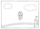
図10は、ボールが上昇(すなわちボールに作用する重力の反対の方向に移動)しているときにモニタ2の画面に表示されるゲーム画像例である。ボールが上昇している間は、ボールが画面の中央に表示されるので、スタンドや雲などの背景要素が勢い良く画面下方に向かって移動し、迫力のある画像が表示される。 FIG. 10 is an example of a game image displayed on the screen of the
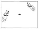
図11は、ボールが下降(すなわちボールに作用する重力と同じ方向に移動)しているときにモニタ2の画面に表示されるゲーム画像例である。ボールが下降している間は、ボール自体ではなく、ボールの影(ただし、ボールの影は、ボールを通る鉛直線とフィールドとが交差する地点に表示されるものとする)が画面の中央に表示されるので、プレイヤは、ボールの真下の地点や予定落下地点等の様子を画像から把握でき、例えば、ボールの予定落下地点に向かって走る他の野手の動きや、ボールがファウルラインの外側を飛んでいるのかファイルラインの内側を飛んでいるのかなどを画面上で確認することができる。 FIG. 11 is an example of a game image displayed on the screen of the
図9〜図11のようなゲーム画像は、仮想3次元空間内に設定された仮想カメラに基づく透視投影変換処理によって生成される。特に、図10や図11のゲーム画像を生成するためには、ボールの移動に応じて仮想カメラを制御する必要がある。以下、図12〜図15を参照して、本実施形態における仮想カメラの制御方法について説明する。 Game images as shown in FIGS. 9 to 11 are generated by a perspective projection conversion process based on a virtual camera set in a virtual three-dimensional space. In particular, in order to generate the game images of FIGS. 10 and 11, it is necessary to control the virtual camera in accordance with the movement of the ball. Hereinafter, a virtual camera control method according to the present embodiment will be described with reference to FIGS.
図12は、ボールが上昇しているときの仮想カメラの様子を示している。 FIG. 12 shows the state of the virtual camera when the ball is rising.
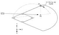
なお、仮想3次元空間内のボールや仮想カメラの位置は、互いに直交する3つの座標軸(X軸、Y軸、Z軸)を用いたワールド座標によって表される。本実施形態では、一例として、X軸は三塁ベースから一塁ベースに向かう方向に関する座標軸であり、Y軸は鉛直上方向(すなわち重力の反対方向)に関する座標軸であり、Z軸は本塁から二塁ベースに向かう方向に関する座標軸であるものとする。仮想カメラは、ボールの軌道に応じて(例えば、ボールの移動方向や飛距離や到達高度に応じて)異なる位置に設置される。図12〜図14の例では、仮想カメラは本塁の後方(すなわちバックネットのあたり)に設置されている。 Note that the position of the ball or virtual camera in the virtual three-dimensional space is represented by world coordinates using three coordinate axes (X axis, Y axis, Z axis) orthogonal to each other. In this embodiment, as an example, the X axis is a coordinate axis related to the direction from the third base to the first base, the Y axis is a coordinate axis related to the vertically upward direction (that is, the opposite direction of gravity), and the Z axis is from the main base to the second base. It is assumed that it is a coordinate axis with respect to the direction of heading. The virtual camera is installed at a different position according to the trajectory of the ball (for example, according to the moving direction of the ball, the flight distance, and the reaching altitude). In the examples of FIGS. 12 to 14, the virtual camera is installed behind the main wall (that is, around the back net).
図12のように、ボールが上昇している間は、ボールの現在位置に仮想カメラの注視点が設定される。なお、ボールの速度をワールド座標を用いた速度ベクトルV=(Vx,Vy,Vz)で表せば、「ボールが上昇している間」は「Vyが正である間」と言い換えることができる。 As shown in FIG. 12, while the ball is rising, the gazing point of the virtual camera is set at the current position of the ball. If the velocity of the ball is expressed by a velocity vector V = (Vx, Vy, Vz) using world coordinates, “while the ball is rising” can be rephrased as “while Vy is positive”.
図13は、ボールが上昇から下降に転じる瞬間(すなわちVyが0となる時点)における仮想カメラの様子を示している。ボールが上昇から下降に転じるとき、仮想カメラの注視点は、ボールの位置からボールの影の地点へと移動する。このとき、仮想カメラの注視点は、瞬時にボールの現在位置からボールの影の地点へと移動してもよいし、ボールの現在位置を離れてボールの影の地点へ徐々に近づくように移動してもよい。 FIG. 13 shows the state of the virtual camera at the moment when the ball changes from rising to falling (that is, when Vy becomes 0). When the ball turns from rising to falling, the point of sight of the virtual camera moves from the position of the ball to the point of the shadow of the ball. At this time, the gazing point of the virtual camera may instantaneously move from the current position of the ball to the point of the ball shadow, or move away from the current position of the ball and gradually approach the point of the ball shadow. May be.
図14は、ボールが下降しているときの仮想カメラの様子を示している。ボールが下降している間(すなわちVyが負である間)は、ボールの影の地点に仮想カメラの注視点が設定される。 FIG. 14 shows the state of the virtual camera when the ball is descending. While the ball is descending (that is, while Vy is negative), the gazing point of the virtual camera is set at the shadow point of the ball.
なお、上記のような注視点の制御に加えて、ボールの移動に応じて仮想カメラの画角も変化する。図15は、本塁からボールまでの距離と、仮想カメラの画角との対応関係を示している。図15に示すように、本塁からボールまでの距離が14mから80mまでの間は、本塁からボールまでの距離が長くなるほど仮想カメラの画角は小さくなる。すなわち、ボールが本塁から遠ざかるにつれて仮想カメラの倍率が高くなるので、仮想カメラからボールが遠ざかっていっても、画面上でボールがどんどん小さくなってしまうことは無く、迫力のあるゲーム画像が表示される。 In addition to the control of the gazing point as described above, the angle of view of the virtual camera also changes according to the movement of the ball. FIG. 15 shows the correspondence between the distance from the main ball to the ball and the angle of view of the virtual camera. As shown in FIG. 15, when the distance from the main ball to the ball is 14 m to 80 m, the angle of view of the virtual camera decreases as the distance from the main ball to the ball increases. In other words, the magnification of the virtual camera increases as the ball moves away from the home base, so even if the ball moves away from the virtual camera, the ball does not get smaller and smaller on the screen, and a powerful game image is displayed. The
ところで、一般的に仮想カメラの画角が小さいほど(すなわち仮想カメラの倍率が高いほど)、画面に表示される画像はより迫力のある画像となるが、視野が狭くなるために画面に表示される情報量は減ってしまう。しかしながら、本実施形態では前述のように、ボールが上昇から下降に転じたときに仮想カメラの注視点をボール自体の位置からボールの影の地点へと移動させるので、迫力のある表示のために仮想カメラの画角を小さくしたとしても、プレイヤは、ボールの真下の地点や予定落下地点等の様子を画像から把握できる。 By the way, in general, the smaller the angle of view of the virtual camera (that is, the higher the magnification of the virtual camera), the more powerful the image displayed on the screen. The amount of information that will be reduced. However, in this embodiment, as described above, when the ball changes from rising to falling, the point of sight of the virtual camera is moved from the position of the ball itself to the shadow point of the ball. Even if the angle of view of the virtual camera is reduced, the player can grasp the situation such as the point directly under the ball or the planned fall point from the image.
以下、上記のような仮想カメラの制御を実現するためのゲーム装置3の詳細な動作を説明する。 Hereinafter, the detailed operation of the
図16は、ゲーム装置本体5のメインメモリ33のメモリマップの一例である。メインメモリ33には、ゲームプログラム330,仮想カメラ制御変数,ボール制御変数,および影地点座標337が格納される。ゲームプログラム330は、ゲームの開始前に光ディスク4からメインメモリ33にロードされる。仮想カメラ制御変数,ボール制御変数および影地点座標は、ゲームプログラム330に基づくゲーム処理時にCPU30によって適宜に更新される。 FIG. 16 is an example of a memory map of the
仮想カメラ制御変数には、視点座標331,現在注視点座標332,目標注視点座標333および画角334が含まれる。視点座標331は、仮想3次元空間における仮想カメラの位置を示す3次元座標である。現在注視点座標332は、仮想カメラの注視点の現在位置を示す3次元座標であり、目標注視点座標333は、仮想カメラの注視点の目標位置を示す3次元座標である。なお、目標注視点座標333は、現在注視点座標332を更新するときに参照されるだけであり、実際のゲーム画像の描画処理では現在注視点座標332が用いられる。画角334は、仮想カメラの画角である。 The virtual camera control variables include a viewpoint coordinate 331, a current gazing point coordinate 332, a target gazing point coordinate 333, and an angle of
ボール制御変数には、現在位置座標335および速度ベクトル336が含まれる。現在位置座標335は、仮想3次元空間におけるボールの現在位置を示す3次元座標である。速度ベクトル336は、ボールの移動速度(大きさおよび方向を含む)を示す3次元ベクトルである。 The ball control variable includes a current position coordinate 335 and a
影地点座標337は、仮想3次元空間におけるボールの影の地点(より正確には、ボールを通る鉛直線とフィールドとが交差する地点)の3次元座標である。 The shadow point coordinates 337 are three-dimensional coordinates of the shadow point of the ball in the virtual three-dimensional space (more precisely, the point where the vertical line passing through the ball and the field intersect).
次に、図17および図18のフローチャートを参照して、ゲームプログラム330に基づくCPU30の動作を説明する。なお、図17のフローチャートでは、便宜上、ゲーム画像の描画処理(仮想カメラに基づく透視投影変換処理)を省略しているが、実際には一定の周期(例えば16.7msecの周期)でゲーム画像の描画処理が行われてモニタ2の画面に表示されるゲーム画像が更新される。 Next, the operation of the
図17において、メイン処理が開始されると、CPU30はステップS10で、ゲームが終了したかどうかを判断する。そして、ゲームが終了した場合にはメイン処理を終了し、ゲームが終了していない場合には処理はステップS12に進む。 In FIG. 17, when the main process is started, the
ステップS12では、CPU30は仮想カメラ制御変数を初期化する。具体的には、図9のようなゲーム画像が生成できるように仮想カメラの視点座標331,現在注視点座標332,目標注視点座標333および画角334が設定される。 In step S12, the
ステップS14では、CPU30は、投手が投球を開始するかどうかを例えばタイマの値により判断する。そして、投手が投球を開始した場合には処理はステップS16に進む。 In step S14, the
ステップS16では、CPU30はボールの速度ベクトル336を更新する。具体的には、重力,空気抵抗およびボールの回転方向(ストレート,カーブ,シュート,フォーク等)に応じてボールの速度ベクトル336が更新される。 In step S16, the
ステップS18では、CPU30はステップS16で更新された速度ベクトル336に応じてボールの現在位置座標335を更新する。ステップS18の処理が一定の周期で繰り返し実行されることによって、ボールが投手から捕手へ向かって移動するアニメーション表示が実現される。 In step S18, the
ステップS20では、CPU30は、ボールの現在位置座標335を参照して、ボールが捕手に到達したかどうかを判断する。そして、ボールが捕手に到達した場合には処理はステップS10に戻り、ボールが捕手に到達していない場合には処理はステップS22に進む。 In step S20, the
ステップS22では、CPU30は、通信ユニット6によって受信されるコントローラ7からの操作情報に基づいて、プレイヤによってスイング操作が行われたかどうかを判断する。そして、スイング操作が行われた場合には処理はステップS24に進み、スイング操作が行われていない場合には処理はステップS16に戻る。 In step S <b> 22, the
ステップS24では、CPU30は、打者が持つバットの位置を更新する。ステップS24の処理が一定の周期で繰り返し実行されることによって、打者がバットを振るアニメーション表示が実現される。 In step S24, the
ステップS26では、CPU30は、ボールの現在位置座標335とバットの現在位置に基づいて、ボールがバットに当たったかどうかを判断する。そして、ボールがバットに当たった場合には処理はステップS28に進み、ボールがバットに当たっていない場合には処理はステップS16に戻る。 In step S26, the
ステップS28では、CPU30はボールの初速度(大きさおよび方向)を決定し、決定された初速度に応じてボールの速度ベクトル336を更新する。 In step S28, the
ステップS30では、ステップS28で決定された初速度からボールの軌道を計算し、計算されたボールの軌道に応じて仮想カメラの視点座標331を決定する。例えば、ボールの軌道がライト方向の場合は一塁側スタンドのあたりに仮想カメラの視点座標331を設定し、ボールの軌道がセンター方向の場合はバックスタンドのあたりに仮想カメラの視点座標331を設定し、ボールの軌道がレフト方向の場合は三塁側スタンドのあたりに仮想カメラの視点座標331を設定する。 In step S30, the ball trajectory is calculated from the initial velocity determined in step S28, and the viewpoint coordinates 331 of the virtual camera are determined according to the calculated ball trajectory. For example, when the ball trajectory is in the light direction, the virtual camera viewpoint coordinates 331 are set around the first stand, and when the ball trajectory is in the center direction, the virtual camera viewpoint coordinates 331 are set around the back stand. When the ball trajectory is in the left direction, the viewpoint coordinates 331 of the virtual camera are set around the third base stand.
ステップS32では、CPU30はボールの速度ベクトル336を更新する。具体的には、重力,空気抵抗に応じてボールの速度ベクトル336が更新される。ステップS32の処理が一定の周期で繰り返し実行されることによって、ボールの速度ベクトル336のY座標値Vyは重力の影響によって徐々に減少する。 In step S32, the
ステップS34では、CPU30はステップS32で更新された速度ベクトル336に応じてボールの現在位置座標335を更新する。ステップS34の処理が一定の周期で繰り返し実行されることによって、フィールドの上方をボールが略放物線状に移動するアニメーション表示が実現される。 In step S34, the
ステップS36では、CPU30は、打球後(すなわちボールがバットに当たってから)、所定時間以上経過したかどうかを判断する。そして、所定時間以上経過している場合には処理はステップS38に進み、所定時間以上経過していない場合には処理はステップS40に進む。なお、ステップS36の判断は、ボールがバットに当たった瞬間からカウントを開始するタイマの値を参照することによって行われる。ステップS36の処理は、打球から一定時間は仮想カメラ制御変数を変化させないことによって、打球直後の投手と打者の様子をプレイヤが画面上で確認できるようにするための処理である。 In step S36, the
ステップS38では、CPU30は仮想カメラ制御処理を行う。以下、図18のフローチャートを参照して仮想カメラ制御処理の詳細を説明する。 In step S38, the
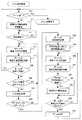
仮想カメラ制御処理が開始されると、ステップS50で、CPU30は、ボールの速度ベクトル336のY座標値が正かどうか(すなわちボールが上昇中かどうか)を判断する。そして、ボールの速度ベクトル336のY座標値が正である場合には処理はステップS52に進み、ボールの速度ベクトル336のY座標値が正でない場合には処理はステップS54に進む。 When the virtual camera control process is started, in step S50, the
ステップS52では、CPU30は、目標注視点座標333としてボールの現在位置座標335を設定する。そして、処理はステップS58に進む。 In step S <b> 52, the
ステップS54では、CPU30は、ボールの現在位置座標335から影地点座標337を計算する。 In step S54, the
ステップS56では、CPU30は、目標注視点座標333として影地点座標337を設定する。そして、処理はステップS58に進む。 In step S <b> 56, the
ステップS58では、CPU30は、ステップS52またはステップS56で更新された目標注視点座標333に基づいて現在注視点座標332を更新する。例えば、更新前の現在注視点座標332をTとし、更新後の現在注視点座標332をT’とし、ボールの現在位置座標335をPとしたとき、更新後の現在注視点座標332であるT’を、T’=T+(P−T)×0.05の計算式により算出してもよい。この場合、現在注視点座標332は、現在注視点座標332と目標注視点座標333の間の距離の大きさに比例した速度で目標注視点座標333に近づくことになる。他の例として、現在注視点座標332が目標注視点座標333に常に一定の速度で近づくように現在注視点座標332を更新するようにしてもよい。さらに他の例として、ボールが上昇から下降に転じたときに、目標注視点座標333がボールの現在位置座標335から影地点座標337に向かって徐々に移動するように、目標注視点座標333を繰り返し更新しても良い。 In step S58, the
上記のように、現在注視点座標332を目標注視点座標333に徐々に近付けることによって、仮想カメラの向きが急激に変化してプレイヤが戸惑ってしまうことを防止することができる。ただし、本発明はこれに限定されず、仮想カメラの注視点をボールの現在位置座標335または影地点座標337に瞬時に移動させるようにしても構わない。 As described above, by gradually bringing the current gazing point coordinates 332 closer to the target gazing point coordinates 333, it is possible to prevent the player from being confused by sudden changes in the orientation of the virtual camera. However, the present invention is not limited to this, and the gazing point of the virtual camera may be instantaneously moved to the current position coordinate 335 or the shadow point coordinate 337 of the ball.
ステップS60では、CPU30は、ボールの現在位置座標335を参照して本塁からボールの現在位置までの距離を計算する。 In step S60, the
ステップS62では、CPU30は、ステップS60で計算された距離と図15の関係とに基づいて、仮想カメラの画角334を更新する。なお、仮想カメラの画角334についても、上記のような現在注視点座標を目標注視点座標に徐々に近付ける処理と同様に、現在画角を目標画角に徐々に近付けるようにしても構わない。これにより、仮想カメラの画角が急激に変化してプレイヤが戸惑ってしまうことを防止することができる。 In step S62, the
以上のような仮想カメラ制御処理が終了すると、処理は図17のステップS40に進む。 When the virtual camera control process as described above ends, the process proceeds to step S40 in FIG.
ステップS40では、CPU30は、ボールの現在位置座標335に基づいて、ボールがフィールドに着地、またはボールが野手に捕球されたかどうかを判断する。そして、ボールが着地または捕球された場合には、処理はステップS42に進み、ボールが着地も捕球もされていない場合には、処理はステップS32に戻る。 In step S40, the
ステップS42では、CPU30は、ボールがフィールドに着地、またはボールが野手に捕球された後のゲーム処理(例えば、走塁処理や送球処理など)を行う。そして、処理はステップS10に戻る。 In step S <b> 42, the
以上のように、本実施形態によれば、ボールが上昇している間は、ボールが画面の中央に表示されるので、スタンドや雲などの背景要素が勢い良く画面下方に向かって移動し、迫力のある画像が表示される。さらに、ボールが下降している間は、ボール自体ではなく、ボールの影が画面の中央に表示されるので、プレイヤは、ボールの真下の地点や予定落下地点等の様子を画像から把握できる。特に、上記のような仮想カメラの注視点の動きは、現実の球場における一般的な観戦者の視線の動きと同じであるため、プレイヤは、あたかも自分が実際に仮想3次元空間内にいるかのような臨場感を味わうことができる。 As described above, according to the present embodiment, while the ball is rising, the ball is displayed in the center of the screen, so background elements such as a stand and clouds move vigorously toward the bottom of the screen, A powerful image is displayed. Further, while the ball is descending, not the ball itself but the shadow of the ball is displayed in the center of the screen, so that the player can grasp from the image the state immediately below the ball, the planned fall point, and the like. In particular, the movement of the gazing point of the virtual camera as described above is the same as the movement of a general spectator's line of sight in a real stadium, so that the player is as if he is actually in the virtual three-dimensional space You can enjoy a sense of realism.
また、本実施形態では、ボールが上昇から下降に転じた時点で仮想カメラの注視点がボールの現在位置からボールの影の地点へと移動するので、常に適したタイミングで仮想カメラの注視点の移動が行われる。より詳しく説明すると、例えば、ボールがバットに当たってから一定時間が経過した時点で仮想カメラの注視点をボールの現在位置からボールの影の地点へと移動するような仮想カメラの制御方法を採用した場合、ボールの滞空時間が長い場合には、最適なタイミングよりも早いタイミングで仮想カメラの注視点の移動が行われてしまい、ボールの滞空時間が短い場合には、最適なタイミングよりも遅いタイミングで仮想カメラの注視点の移動が行われてしまうことになる。しかしながら、本実施形態のような仮想カメラの制御方法によれば、ボールの速度(特に重力方向成分)に基づいて仮想カメラの注視点の移動が行われるので、ボールの滞空時間によらず、常に適したタイミングで仮想カメラの注視点の移動が行われる。 In this embodiment, the virtual camera's point of interest moves from the current position of the ball to the shadow point of the ball when the ball changes from rising to lowering. A move is made. More specifically, for example, when a virtual camera control method is adopted that moves the gazing point of the virtual camera from the current position of the ball to the shadow point of the ball when a certain time has elapsed since the ball hits the bat If the ball's flight time is long, the virtual camera's point of interest moves at an earlier timing than the optimal timing, and if the ball's flight time is short, the timing is later than the optimal timing. The gazing point of the virtual camera is moved. However, according to the control method of the virtual camera as in the present embodiment, the gazing point of the virtual camera is moved based on the velocity of the ball (particularly the gravity direction component), and therefore, always regardless of the ball flight time. The point of interest of the virtual camera is moved at an appropriate timing.
なお、本実施形態では、ボールが上昇から下降に転じた時点(すなわちボールの速度ベクトル336のY座標値が0になった時点)で仮想カメラの注視点がボールの現在位置からボールの影の地点へと移動する例を説明したが、本発明はこれに限定されない。例えば、ボールの速度ベクトル336のY座標値が0以外の予め定められた値(例えば−5)になった時点で、仮想カメラの注視点がボールの現在位置からボールの影の地点へと移動するようにしてもよい。他の例として、ボールの速度ベクトル336の大きさ(つまり√(Vx2+Vy2+Vz2))を監視し、ボールの速度ベクトル336の大きさが減少から増加に転じた時点で、仮想カメラの注視点がボールの現在位置からボールの影の地点へと移動するようにしてもよい。In this embodiment, when the ball turns from rising to lowering (that is, when the Y coordinate value of the
なお、本実施形態では、ボールが下降している間は、ボールの影の地点(図14のP2)に仮想カメラの注視点が設定される例を説明したが、本発明はこれに限定されない。一つの変形例として、図19に示すように、ボールが下降している間は、ボールの予定落下地点P3に仮想カメラの注視点が設定されるようにしても構わない。図20は、この変形例において、ボールが下降しているときにモニタ2の画面に表示されるゲーム画像例である。この変形例においても、プレイヤは、ボールが勢い良く上昇していく様子を迫力のある画像で確認でき、なおかつボールの真下の地点や予定落下地点等の様子を画面上で把握することができる。さらなる変形例として、ボールが下降している間は、ボールの影の地点(図14のP2)とボールの予定落下地点(図19のP3)の中間地点に仮想カメラの注視点が設定されるようにしても構わない。 In the present embodiment, the example in which the gazing point of the virtual camera is set at the shadow point of the ball (P2 in FIG. 14) while the ball is descending has been described, but the present invention is not limited to this. . As one modified example, as shown in FIG. 19, while the ball is descending, the point of gaze of the virtual camera may be set at the planned fall point P3 of the ball. FIG. 20 is an example of a game image displayed on the screen of the
なお、本実施形態では、フィールドの上方をボールが移動する様子を示す画像を生成する例を説明したが、本発明はこれに限定されず、ボール以外の任意のオブジェクトがフィールドの上方を移動する様子を示す画像を生成する場合にも本発明を適用することができる。 In this embodiment, an example in which an image showing a state in which a ball moves above the field has been described. However, the present invention is not limited to this, and any object other than the ball moves above the field. The present invention can also be applied when generating an image showing a state.
1 ゲームシステム
2 モニタ
2a スピーカ
3 ゲーム装置
30 CPU
31 メモリコントローラ
32 GPU
33 メインメモリ
34 DSP
35 ARAM
36 コントローラI/F
37 ビデオI/F
38 フラッシュメモリ
39 オーディオI/F
4 光ディスク
40 ディスクドライブ
41 ディスクI/F
42 LED制御部
5 ゲーム装置本体
6 通信ユニット
7 コントローラ
700 基板
701 加速度センサ
702 LED
703 水晶振動子
704 バイブレータ
705 電池
706 スピーカ
707 サウンドIC
708 アンプ
71 ハウジング
72 操作部
73 コネクタ
74 撮像情報演算部
741 赤外線フィルタ
742 レンズ
743 撮像素子
744 画像処理回路
75 通信部
751 マイコン
752 メモリ
753 無線モジュール
754 アンテナ
8 センサバー
8a,8b マーカ1
31
33
35 ARAM
36 Controller I / F
37 Video I / F
38
4
42
703
708
Claims (14)
Translated fromJapanese前記フィールドの上方を前記移動オブジェクトが略放物線状に移動するように、前記仮想3次元空間における当該移動オブジェクトの位置を示す位置情報を周期的に更新する移動制御ステップ、
前記移動制御ステップで移動制御される前記移動オブジェクトの速度が特定条件を満たしたか否かを判定する条件判定ステップ、
前記移動オブジェクトの速度が前記特定条件を満たしていなければ、前記仮想カメラの注視点を前記移動オブジェクトの現在位置とし、前記移動オブジェクトの速度が前記特定条件を満たしたことに応じて、前記仮想カメラの注視点を前記移動オブジェクトの現在位置からフィールド上の特定地点へと移動させる注視点制御ステップ、および
前記注視点制御ステップで制御された前記仮想カメラの注視点に基づいて、前記仮想カメラから見える前記仮想3次元空間を表すゲーム画像を、前記表示画面上に表示すべきゲーム画像として生成する画像生成ステップを実行させる、ゲームプログラム。A game image showing a state in which the upper set field in virtual three-dimensional space moving objectmoves,the computer of the game apparatus for displaying on a display screenbased on the virtual camera set in the virtual three-dimensional space,
A movement control step of periodically updating position information indicating the position of the moving object in the virtual three-dimensional space so that the moving object moves in a substantially parabolic shape above the field;
A condition determination step for determining whether or not the speed of the moving object that is movement-controlled in the movement control step satisfies a specific condition;
If the speed of the moving object does not satisfy the specific condition, the virtual camera is set to the current position of the moving object as the gazing point of the virtual camera, and in response to the speed of the moving object satisfying the specific condition, A gazing point control step of moving the gazing point of the moving object from the current position of the moving object to a specific point on the field, and
Before SLbased on the gaze pointof the virtual camera that is controlled by fixation point controlstep, an imageof the game images representing the virtual three-dimensional space viewed from the virtual camera to generatea game image to be displayed on the display screenthe generation step torun, game program.
地点へ徐々に近づくように繰り返し更新される、請求項9に記載のゲームプログラム。The game program according to claim 9, wherein in the gazing point control step, the gazing point of the virtual camera is repeatedly updated so as to gradually approach the specific point at a constant speed.
前記フィールドの上方を前記移動オブジェクトが略放物線状に移動するように、前記仮想3次元空間における当該移動オブジェクトの位置を示す位置情報を周期的に更新する移動制御手段、
前記移動制御手段により移動制御される前記移動オブジェクトの速度が特定条件を満たしたか否かを判定する条件判定手段、
前記移動オブジェクトの速度が前記特定条件を満たしていなければ、前記仮想カメラの注視点を前記移動オブジェクトの現在位置とし、前記移動オブジェクトの速度が前記特定条件を満たしたことに応じて、前記仮想カメラの注視点を前記移動オブジェクトの現在位置からフィールド上の特定地点へと移動させる注視点制御手段、および
前記注視点制御手段により制御された前記仮想カメラの注視点に基づいて、前記仮想カメラから見える前記仮想3次元空間を表すゲーム画像を、前記表示画面上に表示すべきゲーム画像として生成する画像生成手段を備えた、ゲーム装置。A game device that displays a game image showing a moving object moving above a field set in avirtual three-dimensional space on a display screenbased on a virtual camera set in the virtual three-dimensional space. ,
Movement control means for periodically updating position information indicating the position of the moving object in the virtual three-dimensional space so that the moving object moves in a substantially parabolic shape above the field;
Condition judging means for judging whether or not the speed of the moving object whose movement is controlled by the movement control means satisfies a specific condition;
If the speed of the moving object does not satisfy the specific condition, the virtual camera is set to the current position of the moving object as the gazing point of the virtual camera, and in response to the speed of the moving object satisfying the specific condition, Gazing point control means for moving the gazing point of the moving object from the current position of the moving object to a specific point on the field, and
Before SLbased on the gaze pointof the virtual camera that is controlled by the fixation point controlmeans, an imagein which the game images representing the virtual three-dimensional space viewed from the virtual camera to generatea game image to be displayed on the display screen A game device provided with a generating means.
前記フィールドの上方を前記移動オブジェクトが略放物線状に移動するように、前記仮想3次元空間における当該移動オブジェクトの位置を示す位置情報を周期的に更新する移動制御手段、Movement control means for periodically updating position information indicating the position of the moving object in the virtual three-dimensional space so that the moving object moves in a substantially parabolic shape above the field;
前記移動制御手段により移動制御される前記移動オブジェクトの速度が特定条件を満たしたか否かを判定する条件判定手段、Condition judging means for judging whether or not the speed of the moving object whose movement is controlled by the movement control means satisfies a specific condition;
前記移動オブジェクトの速度が前記特定条件を満たしていなければ、前記仮想カメラの注視点を前記移動オブジェクトの現在位置とし、前記移動オブジェクトの速度が前記特定条件を満たしたことに応じて、前記仮想カメラの注視点を前記移動オブジェクトの現在位置からフィールド上の特定地点へと移動させる注視点制御手段、およびIf the speed of the moving object does not satisfy the specific condition, the virtual camera is set to the current position of the moving object as the gazing point of the virtual camera, and in response to the speed of the moving object satisfying the specific condition, Gazing point control means for moving the gazing point of the moving object from the current position of the moving object to a specific point on the field, and
前記注視点制御手段により制御された前記仮想カメラの注視点に基づいて、前記仮想カメラから見える前記仮想3次元空間を表すゲーム画像を、前記表示画面上に表示すべきゲーム画像として生成する画像生成手段を備えた、ゲームシステム。Image generation for generating a game image representing the virtual three-dimensional space visible from the virtual camera as a game image to be displayed on the display screen based on the gazing point of the virtual camera controlled by the gazing point control means A game system comprising means.
前記ゲームシステムの移動制御手段によって、前記フィールドの上方を前記移動オブジェクトが略放物線状に移動するように、前記仮想3次元空間における当該移動オブジェクトの位置を示す位置情報を周期的に更新する移動制御ステップ、Movement control for periodically updating position information indicating the position of the moving object in the virtual three-dimensional space so that the moving object moves in a substantially parabolic shape above the field by the movement control means of the game system. Step,
前記ゲームシステムの条件判定手段によって、前記移動制御ステップで移動制御される前記移動オブジェクトの速度が特定条件を満たしたか否かを判定する条件判定ステップ、A condition determination step for determining whether or not the speed of the moving object controlled to move in the movement control step satisfies a specific condition by the condition determination means of the game system;
前記ゲームシステムの注視点制御手段によって、前記移動オブジェクトの速度が前記特定条件を満たしていなければ、前記仮想カメラの注視点を前記移動オブジェクトの現在位置とし、前記移動オブジェクトの速度が前記特定条件を満たしたことに応じて、前記仮想カメラの注視点を前記移動オブジェクトの現在位置からフィールド上の特定地点へと移動させる注視点制御ステップ、およびIf the speed of the moving object does not satisfy the specific condition by the gaze point control means of the game system, the gaze point of the virtual camera is set as the current position of the moving object, and the speed of the moving object satisfies the specific condition. A gazing point control step of moving the gazing point of the virtual camera from the current position of the moving object to a specific point on the field according to the satisfaction, and
前記ゲームシステムの画像生成手段によって、前記注視点制御ステップで制御された前記仮想カメラの注視点に基づいて、前記仮想カメラから見える前記仮想3次元空間を表すゲーム画像を、前記表示画面上に表示すべきゲーム画像として生成する画像生成ステップを備える、ゲーム処理方法。Based on the gazing point of the virtual camera controlled in the gazing point control step, the game image representing the virtual three-dimensional space visible from the virtual camera is displayed on the display screen by the image generation unit of the game system. A game processing method comprising an image generation step of generating a game image to be performed.
Priority Applications (2)
| Application Number | Priority Date | Filing Date | Title |
|---|---|---|---|
| JP2006310617AJP5294554B2 (en) | 2006-11-16 | 2006-11-16 | GAME PROGRAM, GAME DEVICE, GAME SYSTEM, AND GAME PROCESSING METHOD |
| US11/645,633US8012004B2 (en) | 2006-11-16 | 2006-12-27 | Computer-readable storage medium having game program stored thereon and game apparatus |
Applications Claiming Priority (1)
| Application Number | Priority Date | Filing Date | Title |
|---|---|---|---|
| JP2006310617AJP5294554B2 (en) | 2006-11-16 | 2006-11-16 | GAME PROGRAM, GAME DEVICE, GAME SYSTEM, AND GAME PROCESSING METHOD |
Publications (2)
| Publication Number | Publication Date |
|---|---|
| JP2008125550A JP2008125550A (en) | 2008-06-05 |
| JP5294554B2true JP5294554B2 (en) | 2013-09-18 |
Family
ID=39417575
Family Applications (1)
| Application Number | Title | Priority Date | Filing Date |
|---|---|---|---|
| JP2006310617AActiveJP5294554B2 (en) | 2006-11-16 | 2006-11-16 | GAME PROGRAM, GAME DEVICE, GAME SYSTEM, AND GAME PROCESSING METHOD |
Country Status (2)
| Country | Link |
|---|---|
| US (1) | US8012004B2 (en) |
| JP (1) | JP5294554B2 (en) |
Families Citing this family (9)
| Publication number | Priority date | Publication date | Assignee | Title |
|---|---|---|---|---|
| JP5089079B2 (en)* | 2006-05-08 | 2012-12-05 | 任天堂株式会社 | Program, information storage medium, and image generation system |
| US20080222351A1 (en)* | 2007-03-07 | 2008-09-11 | Aprius Inc. | High-speed optical connection between central processing unit and remotely located random access memory |
| JP5535458B2 (en)* | 2008-08-20 | 2014-07-02 | 株式会社コナミデジタルエンタテインメント | Image processing apparatus, image processing method, and program |
| US20100306685A1 (en)* | 2009-05-29 | 2010-12-02 | Microsoft Corporation | User movement feedback via on-screen avatars |
| US20140274369A1 (en)* | 2013-03-12 | 2014-09-18 | Sony Computer Entertainment America Llc | Scheme for assisting in catching an object in a computer simulation |
| JP6395687B2 (en)* | 2015-10-16 | 2018-09-26 | 株式会社カプコン | Video generation method, video generation program, and video generation apparatus |
| JP6392911B2 (en) | 2017-01-30 | 2018-09-19 | 株式会社コロプラ | Information processing method, computer, and program for causing computer to execute information processing method |
| CN109260702A (en)* | 2018-08-30 | 2019-01-25 | 腾讯科技(深圳)有限公司 | Virtual carrier control method, computer equipment and storage medium in virtual scene |
| CN110193198B (en) | 2019-05-23 | 2023-02-10 | 腾讯科技(深圳)有限公司 | Object jump control method, device, computer equipment and storage medium |
Family Cites Families (5)
| Publication number | Priority date | Publication date | Assignee | Title |
|---|---|---|---|---|
| JP3740797B2 (en)* | 1996-07-03 | 2006-02-01 | 株式会社セガ | Baseball game image display method |
| JP2001137554A (en) | 1999-11-10 | 2001-05-22 | Sega Corp | GAME DEVICE AND COMPUTER-READABLE RECORDING MEDIUM RECORDING GAME PROGRAM |
| JP2001175890A (en)* | 1999-12-17 | 2001-06-29 | Sony Corp | System and method for forming three-dimensional image, and input device |
| JP2002058867A (en)* | 2000-06-07 | 2002-02-26 | Square Co Ltd | Computer-readable recording medium with ball game program recorded on it, program, and ball game processing device and method |
| JP4187192B2 (en)* | 2002-07-04 | 2008-11-26 | 株式会社バンダイナムコゲームス | Image generation system, program, and information storage medium |
- 2006
- 2006-11-16JPJP2006310617Apatent/JP5294554B2/enactiveActive
- 2006-12-27USUS11/645,633patent/US8012004B2/enactiveActive
Also Published As
| Publication number | Publication date |
|---|---|
| US20080119285A1 (en) | 2008-05-22 |
| US8012004B2 (en) | 2011-09-06 |
| JP2008125550A (en) | 2008-06-05 |
Similar Documents
| Publication | Publication Date | Title |
|---|---|---|
| JP5173174B2 (en) | GAME DEVICE, GAME PROGRAM, GAME SYSTEM, AND GAME PROCESSING METHOD | |
| JP5188682B2 (en) | GAME DEVICE, GAME PROGRAM, GAME SYSTEM, AND GAME CONTROL METHOD | |
| JP5420824B2 (en) | GAME DEVICE AND GAME PROGRAM | |
| JP4988273B2 (en) | GAME PROGRAM AND GAME DEVICE | |
| JP5294554B2 (en) | GAME PROGRAM, GAME DEVICE, GAME SYSTEM, AND GAME PROCESSING METHOD | |
| US9498709B2 (en) | Game controller and game system | |
| JP5334595B2 (en) | GAME DEVICE AND GAME PROGRAM | |
| JP4989105B2 (en) | Game controller | |
| JP5131809B2 (en) | GAME DEVICE AND GAME PROGRAM | |
| US8870655B2 (en) | Wireless game controllers | |
| CN1923325B (en) | Game system | |
| JP5177735B2 (en) | GAME PROGRAM AND GAME DEVICE | |
| US20070049374A1 (en) | Game system and storage medium having game program stored thereon | |
| JP4919887B2 (en) | Image processing program and image processing apparatus | |
| JP2011065251A (en) | Information processing program and apparatus | |
| JP5498690B2 (en) | GAME PROGRAM AND GAME DEVICE | |
| JP4917347B2 (en) | GAME DEVICE AND GAME PROGRAM | |
| JP5392986B2 (en) | Game system and game program | |
| JP2010131321A (en) | Game apparatus and game program | |
| JP5563790B2 (en) | GAME DEVICE AND GAME PROGRAM |
Legal Events
| Date | Code | Title | Description |
|---|---|---|---|
| A621 | Written request for application examination | Free format text:JAPANESE INTERMEDIATE CODE: A621 Effective date:20091020 | |
| RD02 | Notification of acceptance of power of attorney | Free format text:JAPANESE INTERMEDIATE CODE: A7422 Effective date:20110902 | |
| RD03 | Notification of appointment of power of attorney | Free format text:JAPANESE INTERMEDIATE CODE: A7423 Effective date:20120713 | |
| A131 | Notification of reasons for refusal | Free format text:JAPANESE INTERMEDIATE CODE: A131 Effective date:20121030 | |
| A521 | Request for written amendment filed | Free format text:JAPANESE INTERMEDIATE CODE: A523 Effective date:20121207 | |
| TRDD | Decision of grant or rejection written | ||
| A01 | Written decision to grant a patent or to grant a registration (utility model) | Free format text:JAPANESE INTERMEDIATE CODE: A01 Effective date:20130611 | |
| A61 | First payment of annual fees (during grant procedure) | Free format text:JAPANESE INTERMEDIATE CODE: A61 Effective date:20130611 | |
| R150 | Certificate of patent or registration of utility model | Free format text:JAPANESE INTERMEDIATE CODE: R150 Ref document number:5294554 Country of ref document:JP Free format text:JAPANESE INTERMEDIATE CODE: R150 | |
| R250 | Receipt of annual fees | Free format text:JAPANESE INTERMEDIATE CODE: R250 | |
| R250 | Receipt of annual fees | Free format text:JAPANESE INTERMEDIATE CODE: R250 | |
| R250 | Receipt of annual fees | Free format text:JAPANESE INTERMEDIATE CODE: R250 | |
| R250 | Receipt of annual fees | Free format text:JAPANESE INTERMEDIATE CODE: R250 | |
| R250 | Receipt of annual fees | Free format text:JAPANESE INTERMEDIATE CODE: R250 | |
| R250 | Receipt of annual fees | Free format text:JAPANESE INTERMEDIATE CODE: R250 | |
| R250 | Receipt of annual fees | Free format text:JAPANESE INTERMEDIATE CODE: R250 | |
| R250 | Receipt of annual fees | Free format text:JAPANESE INTERMEDIATE CODE: R250 | |
| R250 | Receipt of annual fees | Free format text:JAPANESE INTERMEDIATE CODE: R250 | |
| R250 | Receipt of annual fees | Free format text:JAPANESE INTERMEDIATE CODE: R250 |