JP5293978B2 - Vehicle generator - Google Patents
Vehicle generatorDownload PDFInfo
- Publication number
- JP5293978B2 JP5293978B2JP2011092172AJP2011092172AJP5293978B2JP 5293978 B2JP5293978 B2JP 5293978B2JP 2011092172 AJP2011092172 AJP 2011092172AJP 2011092172 AJP2011092172 AJP 2011092172AJP 5293978 B2JP5293978 B2JP 5293978B2
- Authority
- JP
- Japan
- Prior art keywords
- circuit
- overvoltage
- voltage
- rotation
- output
- Prior art date
- Legal status (The legal status is an assumption and is not a legal conclusion. Google has not performed a legal analysis and makes no representation as to the accuracy of the status listed.)
- Expired - Fee Related
Links
- 238000004804windingMethods0.000claimsabstractdescription51
- 238000001514detection methodMethods0.000claimsdescription130
- 238000004891communicationMethods0.000claimsdescription17
- 230000005284excitationEffects0.000abstractdescription35
- 238000010248power generationMethods0.000description30
- 230000007257malfunctionEffects0.000description8
- 238000010586diagramMethods0.000description5
- 230000001360synchronised effectEffects0.000description2
- 230000001052transient effectEffects0.000description2
- 238000007796conventional methodMethods0.000description1
- 230000001934delayEffects0.000description1
- 230000008030eliminationEffects0.000description1
- 238000003379elimination reactionMethods0.000description1
- 238000005516engineering processMethods0.000description1
- 230000020169heat generationEffects0.000description1
- 238000012423maintenanceMethods0.000description1
- 238000004519manufacturing processMethods0.000description1
- 230000000737periodic effectEffects0.000description1
- 230000001629suppressionEffects0.000description1
- 230000009466transformationEffects0.000description1
Images


Classifications
- H—ELECTRICITY
- H02—GENERATION; CONVERSION OR DISTRIBUTION OF ELECTRIC POWER
- H02P—CONTROL OR REGULATION OF ELECTRIC MOTORS, ELECTRIC GENERATORS OR DYNAMO-ELECTRIC CONVERTERS; CONTROLLING TRANSFORMERS, REACTORS OR CHOKE COILS
- H02P9/00—Arrangements for controlling electric generators for the purpose of obtaining a desired output
- H02P9/10—Control effected upon generator excitation circuit to reduce harmful effects of overloads or transients, e.g. sudden application of load, sudden removal of load, sudden change of load
Landscapes
- Engineering & Computer Science (AREA)
- Power Engineering (AREA)
- Control Of Eletrric Generators (AREA)
Abstract
Description
Translated fromJapanese本発明は、乗用車やトラック等に搭載される車両用発電機に関する。 The present invention relates to a vehicular generator mounted on a passenger car, a truck, or the like.
車両用発電機は、出力端子に接続された充電線を介してバッテリや各種の電気負荷に充電電力や動作電力を供給している。この車両用発電機の発電動作時に出力端子やバッテリ端子が外れると、ロードダンプと称される過渡的な高電圧が発生する。このとき発生する電圧は、出力電流等にもよるが場合によっては100V以上に達することがある。このようにして発生する高電圧は、電気負荷や車両用発電機内の各種素子の破損の原因になるため、何らかの対策が必要になる。このような対策を行う従来技術としては、例えば車両用発電機のブリッジ回路のローサイド素子をMOSトランジスタで構成し、ロードダンプ発生時に車両用発電機の出力電圧が基準電圧を超えたときにこれらのMOSトランジスタをオンすることにより、高電圧の発生を抑制する保護動作を行うようにした車両用発電装置が知られている(例えば、特許文献1参照。)。この車両用発電装置では、ブリッジ回路のローサイド素子としての各MOSトランジスタをオンすることで出力電圧が再び基準電圧以下になると、各MOSトランジスタは再びオフされ、ブリッジ回路による通常の整流動作が再開されるようになっている。 The vehicular generator supplies charging power and operating power to a battery and various electric loads via a charging line connected to an output terminal. If the output terminal or the battery terminal is disconnected during the power generation operation of this vehicle generator, a transient high voltage called a load dump is generated. The voltage generated at this time may reach 100 V or more depending on the output current or the like. The high voltage generated in this way causes damage to various elements in the electric load and the vehicular generator, and some measures are required. As a conventional technique for taking such measures, for example, a low-side element of a bridge circuit of a vehicular generator is configured by a MOS transistor, and when the output voltage of the vehicular generator exceeds a reference voltage when a load dump occurs, these technologies are used. 2. Description of the Related Art A vehicular power generation device is known that performs a protection operation that suppresses generation of a high voltage by turning on a MOS transistor (see, for example, Patent Document 1). In this vehicular power generation device, when each MOS transistor as the low side element of the bridge circuit is turned on and the output voltage becomes lower than the reference voltage again, each MOS transistor is turned off again, and normal rectification operation by the bridge circuit is resumed. It has become so.
ところで、特許文献1に開示された車両用発電装置では、相電圧が基準電圧を超えたときにローサイド素子としてのMOSトランジスタが整流動作の周期に比べて高速にオン/オフされるため、Gパルス電圧のエネルギーが十分消耗するまでに時間がかかり、高電圧の発生を迅速に終わらせることができなかった。高電圧の発生を短時間に終わらせるためには、相電圧が基準電圧を超えたときにローサイド素子としてのMOSトランジスタを継続的にオンすればよいと考えられる。しかし、車両用発電制御装置(レギュレータ)の中には、相電圧が所定のしきい値電圧を超える周波数に基づいて発電開始を検出して制御動作を開始したり、この検出ができなかったときに異常を通知する警報動作等を行うものがあり、ローサイド素子としてのMOSトランジスタをオフする時間が長くなると、実際には車両用発電機が回転しているにもかかわらず相電圧が所定のしきい値電圧よりも低い状態が継続されるため、発電停止状態に至ったものとして誤検出するおそれがある。この場合に、発電開始に備えて初期励磁電流を界磁巻線に供給するように車両用発電制御装置が制御動作を行うと、無駄に励磁電流を流すとともに、ローサイド素子としてのMOSトランジスタを通して流れる相電流が増加することになるため、発電効率や発熱の観点から望ましくない。また、発電停止状態を誤検出して車両用発電制御装置が誤った警報動作を行うと、運転者が混乱したり、この警報動作に伴って外部制御装置等に誤った信号が出力されることになるため、やはり好ましくはない。 By the way, in the vehicle power generation device disclosed in Patent Document 1, when the phase voltage exceeds the reference voltage, the MOS transistor as the low-side element is turned on / off faster than the cycle of the rectification operation. It took time until the voltage energy was sufficiently consumed, and the generation of the high voltage could not be terminated quickly. In order to end the generation of the high voltage in a short time, it is considered that the MOS transistor as the low side element should be continuously turned on when the phase voltage exceeds the reference voltage. However, in the vehicle power generation control device (regulator), when the start of power generation is detected based on the frequency at which the phase voltage exceeds a predetermined threshold voltage, the control operation is started, or when this detection cannot be performed. If the time to turn off the MOS transistor as the low-side element becomes long, the phase voltage is not set in spite of the fact that the vehicle generator is rotating. Since the state lower than the threshold voltage is continued, there is a possibility of erroneous detection that the power generation is stopped. In this case, when the vehicle power generation control device performs control operation so as to supply the initial excitation current to the field winding in preparation for the start of power generation, the excitation current flows unnecessarily and also flows through the MOS transistor as the low-side element. Since the phase current increases, it is not desirable from the viewpoint of power generation efficiency and heat generation. In addition, if the power generation stop state is erroneously detected and the vehicle power generation control device performs an erroneous alarm operation, the driver may be confused or an erroneous signal may be output to the external control device or the like with this alarm operation. After all, it is not preferable.
本発明は、このような点に鑑みて創作されたものであり、その目的は、ロードダンプ時の高電圧発生を迅速に終わらせるとともに、発電停止状態の誤検出による誤動作を防止することができる車両用発電機を提供することにある。 The present invention was created in view of the above points, and its purpose is to quickly terminate the generation of a high voltage during load dump and to prevent malfunction due to erroneous detection of a power generation stop state. The object is to provide a vehicular generator.
上述した課題を解決するために、本発明の車両用発電機は、回転子の界磁極を磁化させる界磁巻線と、界磁極によって発生する回転磁界によって交流電圧を発生する電機子巻線を有する固定子と、電機子巻線の出力端に接続され、バッテリの高電位端子および低電位端子の少なくとも一方と出力端との間に接続されたスイッチング素子を有し、電機子巻線で発生した電圧を整流するブリッジ回路と、電機子巻線の相電圧に基づいて回転子の回転の有無を検出する回転検出回路と、回転検出回路によって回転子の回転が検出されたときに、界磁巻線に流れる界磁電流を制御してブリッジ回路の出力電圧を第1の電圧値に維持する第1の制御回路と、ブリッジ回路の出力電圧が第1の電圧値よりも高い第2の電圧値を超えたときに過電圧を検出する過電圧検出回路と、過電圧検出回路によって過電圧が検出されないときにスイッチング素子をオンオフ制御するとともに、過電圧検出回路によって過電圧が検出されたときにスイッチング素子を連続的にオンする第2の制御回路と、過電圧検出回路によって過電圧が検出されていないときに、回転検出回路の出力信号を第1の制御回路に向けて出力するとともに、過電圧検出回路によって過電圧が検出されたときに、その時点で回転検出回路から第1の制御回路に入力される回転検出内容を維持する信号を第1の制御回路に向けて出力する回転出力維持回路とを備えている。 In order to solve the above-described problems, a vehicle generator according to the present invention includes a field winding that magnetizes a field pole of a rotor, and an armature winding that generates an AC voltage by a rotating magnetic field generated by the field pole. A stator having a switching element connected to the output end of at least one of the high potential terminal and the low potential terminal of the battery and connected to the output end of the armature winding, and generated in the armature winding A bridge circuit that rectifies the generated voltage, a rotation detection circuit that detects the presence or absence of rotation of the rotor based on the phase voltage of the armature winding, and when the rotation of the rotor is detected by the rotation detection circuit, A first control circuit for controlling the field current flowing in the windings to maintain the output voltage of the bridge circuit at a first voltage value; and a second voltage in which the output voltage of the bridge circuit is higher than the first voltage value. Detects overvoltage when the value is exceeded An overvoltage detection circuit; a second control circuit that controls on / off of the switching element when no overvoltage is detected by the overvoltage detection circuit; and When an overvoltage is not detected by the detection circuit, an output signal of the rotation detection circuit is output to the first control circuit, and when an overvoltage is detected by the overvoltage detection circuit, the rotation detection circuit at that time A rotation output maintaining circuit that outputs a signal for maintaining the rotation detection content input to the first control circuit toward the first control circuit.
第2の制御回路によってスイッチング素子を連続的にオンすることよりロードダンプ時に発生する高電圧を速やかに終わらせることができる。また、スイッチング素子をオンすることにより電機子巻線の相電圧に基づく回転検出ができなくなるが、この場合であっても、過電圧発生時の回転検出内容が維持されるため、実際に回転中の回転子の回転が停止したものとする発電停止状態の誤検出が発生せず、この誤検出に伴う初期励磁電流の供給等の誤動作を防止することができる。 By continuously turning on the switching element by the second control circuit, the high voltage generated during the load dump can be quickly terminated. In addition, turning on the switching element makes it impossible to detect rotation based on the phase voltage of the armature winding, but even in this case, since the rotation detection content at the time of overvoltage occurrence is maintained, The erroneous detection of the power generation stop state that the rotation of the rotor is stopped does not occur, and the malfunction such as the supply of the initial excitation current accompanying the erroneous detection can be prevented.
また、上述した回転出力維持回路は、回転検出内容を所定時間維持することが望ましい。これにより、過電圧発生から所定時間経過までの間の誤動作を確実に防止することができる。 Further, it is desirable that the rotation output maintaining circuit described above maintains the rotation detection content for a predetermined time. As a result, it is possible to reliably prevent malfunctions from the occurrence of overvoltage to the lapse of a predetermined time.
また、上述した所定時間は、過電圧が解消するまでの時間であることが望ましい。これにより、過電圧発生後から過電圧解消までの間の誤動作を確実に防止することができる。 Further, the predetermined time described above is desirably a time until the overvoltage is eliminated. As a result, it is possible to reliably prevent malfunctions after the occurrence of the overvoltage until the overvoltage is eliminated.
また、上述した過電圧検出回路は、ブリッジ回路の出力電圧が第2の電圧値を超えてから、第2の電圧値よりも低く第1の電圧値よりも高い第3の電圧値より低くなるまでを、過電圧として検出することが望ましい。これにより、電機子巻線で発生する電圧が第2の電圧値近傍で変化したときの動作を安定させることができる。 In the above-described overvoltage detection circuit, after the output voltage of the bridge circuit exceeds the second voltage value, it becomes lower than the third voltage value lower than the second voltage value and higher than the first voltage value. Is preferably detected as an overvoltage. Thereby, the operation when the voltage generated in the armature winding changes in the vicinity of the second voltage value can be stabilized.
また、上述した回転出力維持手段の出力に応じて回転状態あるいは非回転状態を示す信号を外部装置に向けて送信する通信回路をさらに備えることが望ましい。これにより、過電圧発生に伴って電機子巻線の相電圧に基づく回転検出ができなくなった場合であっても、それまでの回転状態を示す信号を継続的に外部装置に向けて送信することができる。 Further, it is desirable to further include a communication circuit that transmits a signal indicating a rotation state or a non-rotation state to an external device in accordance with the output of the rotation output maintaining unit. As a result, even when the rotation detection based on the phase voltage of the armature winding cannot be performed due to the occurrence of the overvoltage, a signal indicating the previous rotation state can be continuously transmitted to the external device. it can.
また、上述した過電圧検出回路は、第2の制御回路に対応して過電圧を検出する第1の過電圧検出手段と、回転出力維持回路に対応して過電圧を検出する第2の過電圧検出手段とを別々に備えており、第1および第2の電圧検出手段のそれぞれにおける検出に用いられる第2の電圧値は同一の値を有することが望ましい。これにより、一方の過電圧検出手段が故障した場合であっても他方の過電圧検出手段の検出結果を用いた動作を継続することが可能となる。 The overvoltage detection circuit described above includes a first overvoltage detection unit that detects an overvoltage corresponding to the second control circuit, and a second overvoltage detection unit that detects an overvoltage corresponding to the rotation output maintaining circuit. It is desirable that the second voltage values provided separately and used for detection in each of the first and second voltage detection means have the same value. As a result, even when one of the overvoltage detection means fails, the operation using the detection result of the other overvoltage detection means can be continued.
また、上述した過電圧検出回路は、第2の制御回路に対応して過電圧を検出する第1の過電圧検出手段と、回転出力維持回路に対応して過電圧を検出する第2の過電圧検出手段のいずれか一方を備えており、この備わった第1および第2の電圧検出手段のいずれか一方の検出結果を第2の制御回路と回転出力維持回路の両方で使用することが望ましい。これにより、構成の簡略化によるコスト低減が可能となる。 The overvoltage detection circuit described above includes any one of a first overvoltage detection unit that detects an overvoltage corresponding to the second control circuit and a second overvoltage detection unit that detects an overvoltage corresponding to the rotation output maintaining circuit. It is desirable to use either one of the first and second voltage detection means provided in both the second control circuit and the rotation output maintaining circuit. This makes it possible to reduce costs by simplifying the configuration.
以下、本発明を適用した一実施形態の車両用発電機について、図面を参照しながら説明する。 Hereinafter, a generator for vehicles of one embodiment to which the present invention is applied will be described with reference to the drawings.
図1は、一実施形態の車両用発電機の構成を示す図である。図1に示すように、本実施形態の車両用発電機1は、電機子巻線101、界磁巻線102、ブリッジ回路103、ブリッジ制御回路104、過電圧検出回路105、発電制御装置2を含んで構成されている。この車両用発電機1は、エンジンによりベルトおよびプーリを介して駆動されている。界磁巻線102は、通電されて磁界を発生する。この界磁巻線102は、界磁極(図示せず)に巻装されて回転子を構成しており、この回転子の界磁極を磁化させる。電機子巻線101は、多相巻線(例えばU相、V相、W相からなる三相巻線)であって、電機子鉄心に巻装されて電機子を構成している。この電機子巻線101は、界磁巻線102の発生する回転磁界によって起電力(交流電圧)を発生する。電機子巻線101に誘起される交流電圧がブリッジ回路103に印加される。ブリッジ回路103は、上アーム素子(ハイサイド)および下アーム素子(ローサイド)のそれぞれがスイッチング素子としてのMOSトランジスタによって構成された三相ブリッジ回路であり、電機子巻線101で発生した交流電圧を三相全波整流する。ブリッジ回路103の出力が、車両用発電機1の出力として外部に取り出され、バッテリ3や電気負荷4に供給される。 FIG. 1 is a diagram illustrating a configuration of a vehicle generator according to an embodiment. As shown in FIG. 1, the vehicle generator 1 of this embodiment includes an armature winding 101, a field winding 102, a
ブリッジ制御回路104は、UVWの各相に対応する上アーム素子および下アーム素子としての2つのMOSトランジスタを交互にオンオフするとともに、各相をオンオフする位相を120°交互にずらすことにより、ブリッジ回路103に三相全波整流を行わせる制御を行う。例えば、バッテリ3の高電位端子(プラス端子)に接続される3つのMOSトランジスタについては、それぞれに対応する相巻線の端部に現れる電位がこの高電位端子の電位よりも高くなるタイミングでオンする制御が行われる。また、バッテリ3の低電位端子(マイナス端子)に接続される3つのMOSトランジスタについては、それぞれに対応する相巻線の端部に現れる電位がこの低電位端子の電位よりも低くなるタイミングでオンする制御が行われる。 The
過電圧検出回路105は、ブリッジ回路103の出力電圧に基づいて過電圧を検出する。過電圧検出回路105によって過電圧が検出されると、ブリッジ制御回路104によるロードダンプ対策が実施されて、ブリッジ回路103の低電位端子側の3つのMOSトランジスタが連続的にオンされる。上述した過電圧は、車両用発電機1の出力端子やバッテリ4の高電位端子において充電線が外れたときに発生する。過電圧発生時に低電位端子側の3つのMOSトランジスタを同時かつ連続的にオンすることにより、電機子巻線101のエネルギーを、低電位端子側に接続されたグランド端子Eに流して消費することが可能となる。 The
車両用発電機1の出力(電圧、電流)は、回転子の回転数や界磁巻線102に流れる界磁電流の通電量に応じて変化し、その界磁電流は発電制御装置2によって制御される。発電制御装置2は、車両用発電機1の回転を開始し、回転子が回転しているときに、界磁巻線102に流れる界磁電流を制御して、車両用発電機1の出力端子(B端子)の電圧(ブリッジ回路103の出力電圧)を所定の調整電圧V1に維持する。一方、回転子が非回転状態のときには、発電制御装置2は、界磁巻線102に所定の初期励磁電流(発電を開始するために必要な励磁電流であって、例えば2A程度)を供給する制御を行う。 The output (voltage, current) of the vehicular generator 1 changes according to the number of rotations of the rotor and the amount of field current flowing through the field winding 102, and the field current is controlled by the power generation control device 2. Is done. The power generation control device 2 starts the rotation of the vehicle generator 1 and controls the field current flowing in the field winding 102 when the rotor is rotating, so that the output terminal of the vehicle generator 1 The voltage at the (B terminal) (output voltage of the bridge circuit 103) is maintained at a predetermined adjustment voltage V1. On the other hand, when the rotor is in a non-rotating state, the power generation control device 2 supplies a predetermined initial excitation current (excitation current necessary for starting power generation, for example, about 2 A) to the field winding 102. Take control.
次に、発電制御装置2の詳細構成および動作について説明する。図1に示すように、発電制御装置2は、MOS−FET201、環流ダイオード202、分圧回路203、211、電圧比較器204、212、回転検出回路205、回転出力維持回路206、調整電圧設定回路210、励磁電流制御回路213、過電圧検出回路214、通信回路215、電源回路216を備えている。 Next, the detailed configuration and operation of the power generation control device 2 will be described. As shown in FIG. 1, the power generation control device 2 includes a MOS-
MOS−FET201は、界磁巻線102に直列に接続されており、オン状態のときに界磁巻線102に励磁電流が流れる。環流ダイオード202は、界磁巻線102に並列に接続されており、MOS−FET201がオフ状態のときに励磁電流を環流させる。 The MOS-
分圧回路203は、複数の抵抗によって構成されており、電源回路216によって生成される動作電圧を分圧して回転検出に必要な基準電圧を生成する。電圧比較器204は、分圧回路203によって生成された基準電圧がマイナス端子に入力され、電機子巻線101のいずれかの相の相電圧がプラス端子に入力されており、基準電圧と相電圧とを比較して相電圧の方が基準電圧よりも高いときにハイレベル、低いときにローレベルの信号を出力する。すなわち、電圧比較器204からは、回転子が回転を開始して相電圧の振幅が基準値を超えると、回転数に応じた周期でハイレベルとローレベルが交互に現れる信号が出力され、それ以外(非回転状態)のときにはローレベルに固定された信号が出力される。 The
回転検出回路205は、電圧比較器204の出力信号に基づいて回転子の回転の有無を検出する。具体的には、回転検出回路205は、電圧比較器204からハイレベルとローレベルが交互に現れる信号が出力されると回転子が回転状態にあると判定してハイレベルの信号を出力し、電圧比較器204からローレベルに固定された信号が出力されると回転子が非回転状態にあると判定してローレベルの信号を出力する。 The
過電圧検出回路214は、ブリッジ回路103の出力電圧に基づいて過電圧を検出する。過電圧の検出に対応してハイレベルの信号が出力され、過電圧が検出されていないときにはローレベルの信号が出力される。過電圧検出用に用いられるしきい値電圧V2は、調整電圧V1よりも高い値に設定される。例えば、調整電圧V1が14Vに、しきい値電圧V2が24Vに設定されている。また、このしきい値電圧V2とブリッジ回路103の出力電圧が24V近傍で変化すると、過電圧状態の検出と解除が頻繁に繰り返されることになるため、ブリッジ回路103の出力電圧が上昇していってしきい値電圧V2を超えたときに過電圧状態を検出した後は、このしきい値電圧V2よりも低く調整電圧V1よりも高いしきい値電圧V2よりもブリッジ回路103の出力電圧が低くなるまでは過電圧状態を解除しないようにしてもよい。これにより、ブリッジ回路103の出力電圧がしきい値電圧V2近傍で変化したときの動作を安定させることができる。 The
なお、上述した調整電圧V1が第1の電圧値に、しきい値電圧V2が第2の電圧値に、しきい値電圧V3が第3の電圧値にそれぞれ対応する。また、過電圧検出回路214において過電圧状態の検出に用いられるしきい値電圧V2、V3は、同じ値が過電圧検出回路105における過電圧状態の検出に用いられている。 The adjustment voltage V1 described above corresponds to the first voltage value, the threshold voltage V2 corresponds to the second voltage value, and the threshold voltage V3 corresponds to the third voltage value. Further, the threshold voltages V 2 and
回転出力維持回路206は、過電圧検出回路214によって過電圧が検出されていないときに、回転検出回路205の出力信号を励磁電流制御回路213に向けて出力するとともに、過電圧検出回路205によって過電圧が検出されたときに、その時点(あるいは直前の時点)で回転検出回路205から励磁電流制御回路213に入力されていた回転検出回路205の出力(回転検出内容)を維持する信号を励磁電流制御回路213に向けて出力する。 The rotation
この回転出力維持回路206は、遅延回路207、アンド回路208、オア回路209を含んでいる。遅延回路207は、回転検出回路205から出力される信号を所定時間遅延して出力する。この出力を遅らせる時間が、回転出力維持回路206において回転検出回路205の出力(回転検出内容)を維持する時間となる。この遅延時間(所定時間)は、ロードダンプ発生時の過電圧が解消する時間(この時間は、例えば実際に様々な原因を想定したロードダンプを発生させて測定することができる)よりも長く設定することが望ましい。アンド回路208は、遅延回路207の出力信号と、過電圧検出回路214の出力信号とが入力されており、これらの信号の論理積信号を出力する。過電圧状態になって過電圧検出回路214の出力がハイレベルになると、アンド回路208からは、回転検出回路205の出力信号を遅延回路207によって所定時間遅延させた信号が出力される。オア回路209は、アンド回路208の出力信号と、回転検出回路205の出力信号とが入力されており、これらの信号の論理和信号を出力する。過電圧状態でない場合には、アンド回路208の出力がローレベルを維持するために、オア回路209からは、回転検出回路205から入力される信号がそのまま出力される。一方、過電圧状態の場合には、回転検出回路205の出力と、アンド回路208の出力(回転検出回路205の出力を遅延回路207で所定時間遅延させた信号)との論理和信号が出力される。 The rotation
調整電圧設定回路210は、調整電圧V1に相当する電圧を設定する。分圧回路211は、複数の抵抗によって構成されており、車両用発電機1の出力電圧(ブリッジ回路103の出力電圧)を分圧して、発電電圧に相当する電圧を出力する。電圧比較器212は、分圧回路211によって分圧された電圧がマイナス端子に入力され、調整電圧設定回路210によって生成された調整電圧V1に相当する電圧がプラス端子に入力されており、発電電圧に相当する電圧の方が低いとき(発電電圧の方が調整電圧V1よりも低いとき)にハイレベルの信号を出力する。 The adjustment
励磁電流制御回路213は、電圧比較器212の出力信号と、回転出力維持回路206内のオア回路209の出力信号とが入力されており、これらの信号に基づいてMOS−FET201をオンオフ制御することにより界磁巻線102に流れる界磁電流を制御して、車両用発電機1の出力電圧(ブリッジ回路103の出力電圧)を調整電圧V1に維持する制御を行う。具体的には、この出力電圧を調整電圧V1に維持する制御は、回転子が回転しているとき(回転出力維持回路206からハイレベルの信号が出力されているとき)に行われる。このときには、電圧比較器212の出力がハイレベル(出力電圧の方が調整電圧V1よりも低い)になると、励磁電流制御回路213は、出力電圧を上昇させるために必要な駆動デューティ(通電率)でMOS−FET201をオンオフ制御する。反対に、電圧比較器212の出力がローレベル(出力電圧の方が調整電圧V1よりも高い)になると、励磁電流制御回路213は、出力電圧を低下させるために必要な駆動デューティでMOS−FET201をオンオフ制御する。また、回転子が非回転状態のとき(回転出力維持回路206からローレベルの信号が出力されているとき)には、励磁電流制御回路213は、界磁巻線102に所定の初期励磁電流を供給するために必要な駆動デューティでMOS−FET201をオンオフ制御する。 The excitation
通信回路215は、通信端子Cを介して外部装置としてのECU(例えば、エンジン制御を行う電子制御装置)5との間で各種情報の送受信を行う。例えば、ECU5からは調整電圧V1を指定する情報が送られてくる。通信回路215は、この情報を受信して調整電圧V1を指定する信号を調整電圧設定回路210に入力する。調整電圧設定回路210は、この入力される信号に基づいて調整電圧V1を設定する。これにより、ECU5からの指示に応じて調整電圧V1を任意の値に設定することが可能となる。 The
また、通信回路215には、回転出力維持回路206、励磁電流制御回路213、過電圧検出回路214のそれぞれから出力される信号が入力されている。回転出力維持回路206から入力される信号(オア回路209の出力信号)は、回転/非回転状態を示している。励磁電流制御回路213から入力される信号は、MOS−FET201の駆動デューティを示している。過電圧検出回路214から入力される信号は、過電圧検出の有無(過電圧状態にあるか否か)を示している。通信回路215は、正常な回転時(発電時)にはMOS−FET201の駆動デューティを示す信号を、回転時であって過電圧状態のときにはその旨を示す過電圧警報信号を、非回転時にはその旨を示す回転停止警報信号をECU5に向けて送信する。電源回路216は、発電制御装置2内の各構成の動作に必要な動作電圧を生成する。 The
上述した励磁電流制御回路213、調整電圧設定回路210、分圧回路211、電圧比較器212が第1の制御回路に、ブリッジ制御回路104が第2の制御回路に、過電圧検出回路105が第1の過電圧検出手段に、過電圧検出回路214が第2の過電圧検出回路にそれぞれ対応する。 The excitation
本実施形態の車両用発電機1はこのような構成を有しており、次にその動作を説明する。 The vehicle generator 1 of this embodiment has such a configuration, and the operation thereof will be described next.
(回転停止時の動作)
図2は、回転停止時における励磁電流制御回路213の動作と回転停止警報信号の有無を示す動作タイミング図である。図2において(後述する図5についても同様)、「V3」は電機子巻線101のいずれかの相(例えばW相)の相電圧を、「回転検出回路出力」は回転検出回路205の出力信号を、「遅延回路出力」は遅延回路207の出力信号を、「過電圧検出回路出力」は過電圧検出回路214の出力信号を、「アンド回路出力」はアンド回路208の出力信号を、「オア回路出力」はオア回路209の出力信号をそれぞれ示している。また、「励磁電流制御回路の状態」は励磁電流制御回路213における制御内容であって、「調整電圧制御」は車両用発電機1の出力電圧を調整電圧V1に維持するためにMOS−FET201をオンオフする制御動作を、「初期励磁制御」は低い一定の駆動デューティでMOS−FET201をオンオフする制御動作をそれぞれ示している。また、「警報出力の状態」は通信回路215からECU5に向けて送信される回転停止警報信号の有無を示している。(Operation when rotation stops)
FIG. 2 is an operation timing chart showing the operation of the excitation
回転時には、回転検出回路205は、相電圧V3に同期した電圧比較器204の出力の周期的な変化に基づいて回転子の回転を検出し、ハイレベルの信号を出力する。この信号は、オア回路209を介して励磁電流制御回路213に入力されるため、励磁電流制御回路213は、回転時に車両用発電機1の出力電圧を調整電圧V1に維持する制御を行う。また、オア回路209のハイレベルの出力信号は通信回路215にも入力されており、このハイレベルの信号が入力された通信回路215からは回転停止警報信号の送信は行われない。 At the time of rotation, the
一方、回転状態から回転停止状態に移行すると、回転検出回路205の出力は直ちにハイレベルからローレベルに変化する。過電圧状態でない場合を考えると、このとき、過電圧検出回路214の出力はローレベルであり、アンド回路208の出力もローレベルとなる。したがって、回転検出回路205の出力がハイレベルからローレベルに変化すると、同時に、オア回路209の出力もハイレベルからローレベルに変化する。これにより、励磁電流制御回路213は、初期励磁制御に移行し、低い一定の駆動デューティでMOS−FET201をオンオフする制御を行う。また、オア回路209のローレベルの出力信号は通信回路215にも入力されており、このローレベルの信号が入力されると、通信回路215からECU5に向けて回転停止警報信号の送信が行われる。 On the other hand, when shifting from the rotation state to the rotation stop state, the output of the
(過電圧発生時の動作)
通常の発電動作時(回転時)に、例えば車両用発電機1の出力端子に接続された充電線が外れて、それまでバッテリ3や電気負荷4に供給されていた電流が急に遮断された場合には、車両用発電機1の出力端子にロードダンプと称される過渡的な高電圧が発生する。(Operation when overvoltage occurs)
During normal power generation operation (during rotation), for example, the charging line connected to the output terminal of the vehicle generator 1 is disconnected, and the current supplied to the
図3は、ロードダンプ発生時の車両用発電機1の出力電圧の波形を示す図である。通常の発電動作時には、車両用発電機1の出力電圧は調整電圧V1(14V)に維持されており、ロードダンプ発生時に出力電圧が急激に上昇する。図3において、点線で示された波形はロードダンプ対策がなされていない場合の出力電圧変化を示している。本実施形態では、ロードダンプ発生時の高電圧が過電圧検出回路214によって検出され、ブリッジ制御回路104によるロードダンプ対策が実施されるため、実線の波形で示すようにこの高電圧の程度が抑制される。これにより、発電制御装置2やブリッジ回路103等を構成する各素子が過電圧による故障から保護されるようになっている。 FIG. 3 is a diagram illustrating a waveform of the output voltage of the vehicle generator 1 when a load dump occurs. During normal power generation operation, the output voltage of the vehicular generator 1 is maintained at the adjustment voltage V1 (14V), and the output voltage rapidly increases when a load dump occurs. In FIG. 3, a waveform indicated by a dotted line shows a change in output voltage when no load dump countermeasure is taken. In this embodiment, the high voltage at the time of occurrence of load dump is detected by the
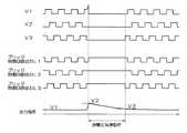
図4は、ロードダンプ発生時のブリッジ制御回路104による過電圧保護動作を示す動作タイミング図である。図4において、「V1〜V3」は電機子巻線101の各相の相電圧を、「ブリッジ制御回路出力L1〜L3」はブリッジ制御回路104から下アーム素子としての3つのMOSトランジスタのそれぞれのゲートに入力される信号(V1とL1、V2とL2、V3とL3がそれぞれ対応している)をそれぞれ示している。 FIG. 4 is an operation timing chart showing an overvoltage protection operation by the
ロードダンプ発生時に出力電圧が急激に上昇して、車両用発電機1の出力電圧がしきい値電圧V2(24V)を超えると、ブリッジ制御回路104は、それまで下アーム素子としての各MOSトランジスタをオンオフしていた信号に代えて、これらの各MOSトランジスタを同時かつ連続的にオンする信号を出力する過電圧保護動作に移行する。なお、このとき上アーム素子としての各MOSトランジスタは同時かつ連続的にオフされる。 When the output voltage suddenly rises when a load dump occurs, and the output voltage of the vehicle generator 1 exceeds the threshold voltage V2 (24V), the
これにより、電機子巻線101に発生した起電力はアース端子を介して流れて消費され、出力電圧をV2から速やかに低下させることができる。そして、出力電圧がV3まで低下したときに過電圧保護動作が終了し、通常の発電動作に復帰する。 As a result, the electromotive force generated in the armature winding 101 flows and is consumed via the ground terminal, and the output voltage can be quickly reduced from V2. Then, when the output voltage drops to V3, the overvoltage protection operation ends and the normal power generation operation is restored.
図5は、ロードダンプ発生時における励磁電流制御回路213の動作と回転停止警報信号の有無を示す動作タイミング図である。 FIG. 5 is an operation timing chart showing the operation of the excitation
ロードダンプ発生時にはブリッジ制御回路104によってブリッジ回路103の下アーム素子としての各MOSトランジスタがオフされるため、相電圧V3に同期した電圧比較器204の出力がローレベルに固定される。このため、回転検出回路205の出力は、ハイレベルからローレベルに変化するが、遅延回路207の出力は、直ちにローレベルには変化せず、所定時間ハイレベルを維持する。また、ロードダンプ発生時には、過電圧検出回路214の出力がハイレベルになる。したがって、遅延回路207と過電圧検出回路214の各出力が入力されるアンド回路208からはハイレベルの信号が出力され、このハイレベルの信号がオア回路209を介して励磁電流制御回路213に入力される。このため、励磁電流制御回路213は、回転検出回路205によって回転状態を検出していないにもかかわらず、車両用発電機1の出力電圧を調整電圧V1に維持する制御を行う。また、オア回路209のハイレベルの出力信号は通信回路215にも入力されており、このハイレベルの信号が入力された通信回路215からは回転停止警報信号の送信は行われない。 When a load dump occurs, each MOS transistor as the lower arm element of the
所定時間以内にロードダンプ発生時の高電圧が解消されると、ブリッジ制御回路104によるブリッジ回路103の通常の制御が再開されるため、回転検出回路205の出力がローレベルからハイレベルになり、この回転検出回路205のハイレベルの信号がオア回路209を介して励磁電流制御回路213に入力される。このため、励磁電流制御回路213は、車両用発電機1の出力電圧を調整電圧V1に維持する制御を継続する。 When the high voltage at the time of occurrence of load dump is eliminated within a predetermined time, the normal control of the
このように、本実施形態の車両用発電機1では、ブリッジ制御回路104によってブリッジ回路103の下アーム素子としての各MOSトランジスタを連続的にオンすることよりロードダンプ時に発生する高電圧を速やかに終わらせることができる。また、各MOSトランジスタを連続的にオンすることにより電機子巻線101の相電圧に基づく回転検出ができなくなるが、この場合であっても、過電圧発生時の回転検出内容が回転出力維持回路206によって維持されるため、実際に回転中の回転子の回転が停止したものとする発電停止状態の誤検出が発生せず、この誤検出に伴う初期励磁電流の供給等の誤動作を防止することができる。 As described above, in the vehicular generator 1 according to the present embodiment, the
また、回転出力維持回路206によって過電圧発生時の回転検出内容を所定時間維持することにより、過電圧発生から所定時間経過までの間の誤動作を確実に防止することができる。また、この所定時間を過電圧が解消するまでの時間とすることにより、過電圧発生後から過電圧解消までの間の誤動作を確実に防止することができる。 Further, by maintaining the rotation detection content at the time of occurrence of the overvoltage for a predetermined time by the rotation
また、過電圧検出回路214は、車両用発電機1の出力電圧(ブリッジ回路103の出力電圧)がしきい値電圧V2を超えてから、この電圧V2よりも低く調整電圧V1よりも高いしきい値電圧V3より低くなるまでを過電圧として検出しており、このように過電圧検出の電圧にヒステリシスを持たせることにより、電機子巻線101で発生する電圧がしきい値電圧V2近傍で変化したときの動作を安定させることができる。 Further, the
また、回転出力維持回路206の出力に応じて回転状態あるいは非回転状態を示す信号を通信回路215から外部のECU5に向けて送信しているため、過電圧発生に伴って電機子巻線101の相電圧に基づく回転検出ができなくなった場合であっても、それまでの回転状態を示す信号を継続的にECU5に向けて送信することができる。 Further, since a signal indicating a rotation state or a non-rotation state is transmitted from the
また、ブリッジ制御回路104に対応して過電圧を検出する過電圧検出回路105と、回転出力維持回路206に対応して過電圧を検出する過電圧検出回路214とを別々に備えており、これら2つの過電圧検出回路105、214のそれぞれにおいて過電圧検出に用いられるしきい値電圧V2、V3を同一の値としている。これにより、一方の過電圧検出回路が故障した場合であっても他方の過電圧検出回路の検出結果を用いた動作を継続することが可能となる。 Further, an
なお、本発明は上記実施形態に限定されるものではなく、本発明の要旨の範囲内において種々の変形実施が可能である。例えば、上述した実施形態では、過電圧検出回路105と過電圧検出回路214とを別々に備えたが、いずれか一方のみを備えて過電圧検出を行い、この検出結果をブリッジ制御回路104と回転出力維持回路206の両方で用いるようにしてもよい。これにより、構成の簡略化によるコスト低減が可能となる。 In addition, this invention is not limited to the said embodiment, A various deformation | transformation implementation is possible within the range of the summary of this invention. For example, in the above-described embodiment, the
また、上述した実施形態では、ブリッジ制御回路104の外部に過電圧検出回路105を備えるようにしたが、過電圧検出回路105をブリッジ制御回路104に内蔵するようにしてもよい。 In the embodiment described above, the
また、上述した実施形態では、上アーム素子と下アーム素子の両方をMOSトランジスタによって構成したが、MOSトランジスタ以外のスイッチング素子を用いるようにしてもよい。また、ロードダンプ時の高電圧抑制に着目した場合には、上アーム素子をスイッチング素子以外の整流素子(例えばダイオード)で構成するようにしてもよい。 In the above-described embodiment, both the upper arm element and the lower arm element are configured by MOS transistors, but switching elements other than MOS transistors may be used. When attention is paid to high voltage suppression at the time of load dump, the upper arm element may be constituted by a rectifying element (for example, a diode) other than the switching element.
上述したように、本発明によれば、ブリッジ制御回路104によってブリッジ回路103の下アーム素子としての各MOSトランジスタを連続的にオンすることよりロードダンプ時に発生する高電圧を速やかに終わらせることができる。また、各MOSトランジスタを連続的にオンすることにより電機子巻線101の相電圧に基づく回転検出ができなくなるが、この場合であっても、過電圧発生時の回転検出内容が回転出力維持回路206によって維持されるため、実際に回転中の回転子の回転が停止したものとする発電停止状態の誤検出が発生せず、この誤検出に伴う初期励磁電流の供給等の誤動作を防止することができる。 As described above, according to the present invention, the high voltage generated at the time of load dump can be quickly terminated by continuously turning on each MOS transistor as the lower arm element of the
1 車両用発電機
2 発電制御装置
3 バッテリ
4 電気負荷
101 電機子巻線
102 界磁巻線
103 ブリッジ回路
104 ブリッジ制御回路
105、214 過電圧検出回路
201 MOS−FET
202 環流ダイオード
203、211 分圧回路
204、212 電圧比較器
205 回転検出回路
206 回転出力維持回路
207 遅延回路
208 アンド回路
209 オア回路
210 調整電圧設定回路
213 励磁電流制御回路
215 通信回路
216 電源回路DESCRIPTION OF SYMBOLS 1 Vehicle generator 2 Power
202
Claims (7)
Translated fromJapanese前記界磁極によって発生する回転磁界によって交流電圧を発生する電機子巻線を有する固定子と、
前記電機子巻線の出力端に接続され、バッテリの高電位端子および低電位端子の少なくとも一方と前記出力端との間に接続されたスイッチング素子を有し、前記電機子巻線で発生した電圧を整流するブリッジ回路と、
前記電機子巻線の相電圧に基づいて前記回転子の回転の有無を検出する回転検出回路と、
前記回転検出回路によって前記回転子の回転が検出されたときに、前記界磁巻線に流れる界磁電流を制御して前記ブリッジ回路の出力電圧を第1の電圧値に維持する第1の制御回路と、
前記ブリッジ回路の出力電圧が前記第1の電圧値よりも高い第2の電圧値を超えたときに過電圧を検出する過電圧検出回路と、
前記過電圧検出回路によって前記過電圧が検出されないときに前記スイッチング素子をオンオフ制御するとともに、前記過電圧検出回路によって前記過電圧が検出されたときに前記スイッチング素子を連続的にオンする第2の制御回路と、
前記過電圧検出回路によって前記過電圧が検出されていないときに、前記回転検出回路の出力信号を前記第1の制御回路に向けて出力するとともに、前記過電圧検出回路によって前記過電圧が検出されたときに、その時点で前記回転検出回路から前記第1の制御回路に入力される回転検出内容を維持する信号を前記第1の制御回路に向けて出力する回転出力維持回路と、
を備えることを特徴とする車両用発電機。Field windings to magnetize the rotor field poles;
A stator having an armature winding that generates an alternating voltage by a rotating magnetic field generated by the field pole;
A voltage generated at the armature winding, having a switching element connected to the output end of the armature winding and connected between at least one of a high potential terminal and a low potential terminal of the battery and the output end A bridge circuit that rectifies
A rotation detection circuit that detects the presence or absence of rotation of the rotor based on the phase voltage of the armature winding;
When the rotation of the rotor is detected by the rotation detection circuit, a first control for controlling the field current flowing in the field winding to maintain the output voltage of the bridge circuit at a first voltage value. Circuit,
An overvoltage detection circuit for detecting an overvoltage when an output voltage of the bridge circuit exceeds a second voltage value higher than the first voltage value;
A second control circuit for controlling on / off of the switching element when the overvoltage is not detected by the overvoltage detection circuit, and continuously turning on the switching element when the overvoltage is detected by the overvoltage detection circuit;
When the overvoltage is not detected by the overvoltage detection circuit, the output signal of the rotation detection circuit is output to the first control circuit, and when the overvoltage is detected by the overvoltage detection circuit, A rotation output maintaining circuit that outputs a signal for maintaining the rotation detection content input from the rotation detection circuit to the first control circuit at that time, toward the first control circuit;
A vehicle generator characterized by comprising:
前記回転出力維持回路は、前記回転検出内容を所定時間維持することを特徴とする車両用発電機。In claim 1,
The rotation output maintaining circuit maintains the rotation detection content for a predetermined time.
前記所定時間は、前記過電圧が解消するまでの時間であることを特徴とする車両用発電機。In claim 2,
The vehicle generator according to claim 1, wherein the predetermined time is a time until the overvoltage is eliminated.
前記過電圧検出回路は、前記ブリッジ回路の出力電圧が前記第2の電圧値を超えてから、前記第2の電圧値よりも低く前記第1の電圧値よりも高い第3の電圧値より低くなるまでを、前記過電圧として検出することを特徴とする車両用発電機。In any one of Claims 1-3,
The overvoltage detection circuit is lower than a third voltage value lower than the second voltage value and higher than the first voltage value after the output voltage of the bridge circuit exceeds the second voltage value. The generator for vehicles is detected as the overvoltage.
前記回転出力維持手段の出力に応じて回転状態あるいは非回転状態を示す信号を外部装置に向けて送信する通信回路をさらに備えることを特徴とする車両用発電機。In any one of Claims 1-4,
A vehicle generator, further comprising a communication circuit that transmits a signal indicating a rotation state or a non-rotation state to an external device in accordance with an output of the rotation output maintaining means.
前記過電圧検出回路は、前記第2の制御回路に対応して前記過電圧を検出する第1の過電圧検出手段と、前記回転出力維持回路に対応して前記過電圧を検出する第2の過電圧検出手段とを別々に備えており、前記第1および第2の電圧検出手段のそれぞれにおける検出に用いられる前記第2の電圧値は同一の値を有することを特徴とする車両用発電機。In any one of Claims 1-5,
The overvoltage detection circuit includes first overvoltage detection means for detecting the overvoltage corresponding to the second control circuit, and second overvoltage detection means for detecting the overvoltage corresponding to the rotation output maintaining circuit. Are provided separately, and the second voltage value used for detection in each of the first and second voltage detection means has the same value.
前記過電圧検出回路は、前記第2の制御回路に対応して前記過電圧を検出する第1の過電圧検出手段と、前記回転出力維持回路に対応して前記過電圧を検出する第2の過電圧検出手段のいずれか一方を備えており、この備わった前記第1および第2の電圧検出手段のいずれか一方の検出結果を前記第2の制御回路と前記回転出力維持回路の両方で使用することを特徴とする車両用発電機。In any one of Claims 1-5,
The overvoltage detection circuit includes: a first overvoltage detection unit that detects the overvoltage corresponding to the second control circuit; and a second overvoltage detection unit that detects the overvoltage corresponding to the rotation output maintaining circuit. Any one of the first and second voltage detection means is used in both the second control circuit and the rotation output maintaining circuit. A vehicle generator.
Priority Applications (3)
| Application Number | Priority Date | Filing Date | Title |
|---|---|---|---|
| JP2011092172AJP5293978B2 (en) | 2011-04-18 | 2011-04-18 | Vehicle generator |
| DE201210103271DE102012103271A1 (en) | 2011-04-18 | 2012-04-16 | A vehicle-mounted generator provided with an overvoltage detection circuit |
| US13/449,982US8841795B2 (en) | 2011-04-18 | 2012-04-18 | On-vehicle generator provided with overvoltage detecting circuit |
Applications Claiming Priority (1)
| Application Number | Priority Date | Filing Date | Title |
|---|---|---|---|
| JP2011092172AJP5293978B2 (en) | 2011-04-18 | 2011-04-18 | Vehicle generator |
Publications (2)
| Publication Number | Publication Date |
|---|---|
| JP2012228033A JP2012228033A (en) | 2012-11-15 |
| JP5293978B2true JP5293978B2 (en) | 2013-09-18 |
Family
ID=46935735
Family Applications (1)
| Application Number | Title | Priority Date | Filing Date |
|---|---|---|---|
| JP2011092172AExpired - Fee RelatedJP5293978B2 (en) | 2011-04-18 | 2011-04-18 | Vehicle generator |
Country Status (3)
| Country | Link |
|---|---|
| US (1) | US8841795B2 (en) |
| JP (1) | JP5293978B2 (en) |
| DE (1) | DE102012103271A1 (en) |
Families Citing this family (7)
| Publication number | Priority date | Publication date | Assignee | Title |
|---|---|---|---|---|
| CN102664568B (en)* | 2012-04-23 | 2014-12-24 | 库顿电子科技(上海)有限公司 | Novel solid-state relay aiming at running direction control of three-phase alternating current motor and method |
| US20170214346A1 (en)* | 2016-01-26 | 2017-07-27 | Cummins Power Generation Ip, Inc. | Reducing moisture using electrical current |
| DE102017204281A1 (en) | 2017-03-15 | 2018-09-20 | Robert Bosch Gmbh | Method for operating a generator |
| TWI674746B (en)* | 2018-05-17 | 2019-10-11 | 朋程科技股份有限公司 | Synchronous rectifier alternator and power allocation method thereof |
| CN111505510B (en)* | 2020-04-21 | 2022-02-11 | 扬州大学 | A non-intrusive substation high-current battery inspection device and its evaluation method |
| IT202000008713A1 (en)* | 2020-04-23 | 2021-10-23 | Nuova Saccardo Motori S R L | PERFECT REGULATION DEVICE FOR REGULATING THE VOLTAGE OF SYNCHRONOUS ALTERNATORS |
| CN112398107B (en)* | 2020-11-13 | 2023-06-09 | 陕西航空电气有限责任公司 | Voltage sampling circuit in overvoltage suppression device of three-phase variable-frequency alternating-current power generation system |
Family Cites Families (11)
| Publication number | Priority date | Publication date | Assignee | Title |
|---|---|---|---|---|
| JPS633Y2 (en) | 1980-03-19 | 1988-01-05 | ||
| JP3323269B2 (en) | 1993-03-12 | 2002-09-09 | マツダ株式会社 | Alternator control device |
| JPH0823700A (en)* | 1994-07-06 | 1996-01-23 | Isuzu Motors Ltd | Generated power supply device |
| JP3491797B2 (en) | 1995-12-05 | 2004-01-26 | 株式会社デンソー | Power generator for vehicles |
| DE19835316A1 (en) | 1998-08-05 | 2000-02-10 | Bosch Gmbh Robert | Controlled rectifier bridge with surge protection |
| JP4172144B2 (en)* | 2000-11-10 | 2008-10-29 | 株式会社デンソー | Field winding type rotating electrical machine |
| JP4487461B2 (en)* | 2001-09-05 | 2010-06-23 | 株式会社デンソー | Generator control system |
| JP3975126B2 (en) | 2002-06-07 | 2007-09-12 | 三菱電機株式会社 | Control device for rotating electrical machine for vehicle |
| US6803748B2 (en)* | 2003-02-03 | 2004-10-12 | Delphi Technologies, Inc. | System and method for controlling load dump voltage of a synchronous machine |
| JP2009183087A (en)* | 2008-01-31 | 2009-08-13 | Denso Corp | Power generation stoppage detecting system |
| JP2012125105A (en)* | 2010-12-10 | 2012-06-28 | Denso Corp | Vehicle generation control device |
- 2011
- 2011-04-18JPJP2011092172Apatent/JP5293978B2/ennot_activeExpired - Fee Related
- 2012
- 2012-04-16DEDE201210103271patent/DE102012103271A1/ennot_activeWithdrawn
- 2012-04-18USUS13/449,982patent/US8841795B2/ennot_activeExpired - Fee Related
Also Published As
| Publication number | Publication date |
|---|---|
| JP2012228033A (en) | 2012-11-15 |
| DE102012103271A1 (en) | 2012-10-18 |
| US20120261983A1 (en) | 2012-10-18 |
| US8841795B2 (en) | 2014-09-23 |
Similar Documents
| Publication | Publication Date | Title |
|---|---|---|
| JP5293978B2 (en) | Vehicle generator | |
| JP4622758B2 (en) | Voltage control device for vehicle | |
| US8547071B2 (en) | Rotary electric machine improved to carry out load-dump protection | |
| JP4229013B2 (en) | AC generator | |
| JP5464367B2 (en) | Rotating electric machine for vehicles | |
| US8339074B2 (en) | Power converter control apparatus | |
| US20130278055A1 (en) | Motor vehicle electrical system having subsystems and a generator system, generator system and method for operating a vehicle electrical system | |
| JP5447261B2 (en) | Vehicle generator | |
| JP3997969B2 (en) | Power generation control device | |
| JP5966946B2 (en) | Vehicle power generation control device | |
| JP4548469B2 (en) | Vehicle power generation control device | |
| JP4200672B2 (en) | Vehicle power generation control device | |
| JP5471929B2 (en) | Vehicle generator | |
| JP5846142B2 (en) | Rotating electric machine for vehicles | |
| JP5494445B2 (en) | Rotating electric machine for vehicles | |
| JP2015002646A (en) | Vehicle power generation controller | |
| JP5924229B2 (en) | Rotating electric machine for vehicles | |
| JP4524663B2 (en) | Voltage control device for vehicle | |
| JP5408060B2 (en) | Vehicle generator | |
| JP2009183087A (en) | Power generation stoppage detecting system | |
| JP5585270B2 (en) | Vehicle generator | |
| JP5896298B2 (en) | Rotating electric machine for vehicles | |
| JP4450085B2 (en) | Vehicle power generation control device | |
| JP2015065788A (en) | Rotary electric machine for vehicle | |
| JP2014087195A (en) | Rotary electric machine for vehicle |
Legal Events
| Date | Code | Title | Description |
|---|---|---|---|
| A621 | Written request for application examination | Free format text:JAPANESE INTERMEDIATE CODE: A621 Effective date:20120824 | |
| A977 | Report on retrieval | Free format text:JAPANESE INTERMEDIATE CODE: A971007 Effective date:20130412 | |
| TRDD | Decision of grant or rejection written | ||
| A01 | Written decision to grant a patent or to grant a registration (utility model) | Free format text:JAPANESE INTERMEDIATE CODE: A01 Effective date:20130515 | |
| A61 | First payment of annual fees (during grant procedure) | Free format text:JAPANESE INTERMEDIATE CODE: A61 Effective date:20130528 | |
| R151 | Written notification of patent or utility model registration | Ref document number:5293978 Country of ref document:JP Free format text:JAPANESE INTERMEDIATE CODE: R151 | |
| R250 | Receipt of annual fees | Free format text:JAPANESE INTERMEDIATE CODE: R250 | |
| R250 | Receipt of annual fees | Free format text:JAPANESE INTERMEDIATE CODE: R250 | |
| R250 | Receipt of annual fees | Free format text:JAPANESE INTERMEDIATE CODE: R250 | |
| R250 | Receipt of annual fees | Free format text:JAPANESE INTERMEDIATE CODE: R250 | |
| R250 | Receipt of annual fees | Free format text:JAPANESE INTERMEDIATE CODE: R250 | |
| R250 | Receipt of annual fees | Free format text:JAPANESE INTERMEDIATE CODE: R250 | |
| R250 | Receipt of annual fees | Free format text:JAPANESE INTERMEDIATE CODE: R250 | |
| LAPS | Cancellation because of no payment of annual fees |