JP5292396B2 - Method for identifying a receiver in a hearing aid - Google Patents
Method for identifying a receiver in a hearing aidDownload PDFInfo
- Publication number
- JP5292396B2 JP5292396B2JP2010513650AJP2010513650AJP5292396B2JP 5292396 B2JP5292396 B2JP 5292396B2JP 2010513650 AJP2010513650 AJP 2010513650AJP 2010513650 AJP2010513650 AJP 2010513650AJP 5292396 B2JP5292396 B2JP 5292396B2
- Authority
- JP
- Japan
- Prior art keywords
- receiver
- hearing aid
- impedance
- signal
- measurement
- Prior art date
- Legal status (The legal status is an assumption and is not a legal conclusion. Google has not performed a legal analysis and makes no representation as to the accuracy of the status listed.)
- Active
Links
- 238000000034methodMethods0.000titledescription32
- 238000005259measurementMethods0.000claimsdescription41
- 238000002847impedance measurementMethods0.000claimsdescription22
- 238000004590computer programMethods0.000description10
- 210000000613ear canalAnatomy0.000description7
- 230000008878couplingEffects0.000description5
- 238000010168coupling processMethods0.000description5
- 238000005859coupling reactionMethods0.000description5
- MOVRNJGDXREIBM-UHFFFAOYSA-Naid-1Chemical compoundO=C1NC(=O)C(C)=CN1C1OC(COP(O)(=O)OC2C(OC(C2)N2C3=C(C(NC(N)=N3)=O)N=C2)COP(O)(=O)OC2C(OC(C2)N2C3=C(C(NC(N)=N3)=O)N=C2)COP(O)(=O)OC2C(OC(C2)N2C3=C(C(NC(N)=N3)=O)N=C2)COP(O)(=O)OC2C(OC(C2)N2C(NC(=O)C(C)=C2)=O)COP(O)(=O)OC2C(OC(C2)N2C3=C(C(NC(N)=N3)=O)N=C2)COP(O)(=O)OC2C(OC(C2)N2C3=C(C(NC(N)=N3)=O)N=C2)COP(O)(=O)OC2C(OC(C2)N2C3=C(C(NC(N)=N3)=O)N=C2)COP(O)(=O)OC2C(OC(C2)N2C(NC(=O)C(C)=C2)=O)COP(O)(=O)OC2C(OC(C2)N2C3=C(C(NC(N)=N3)=O)N=C2)COP(O)(=O)OC2C(OC(C2)N2C3=C(C(NC(N)=N3)=O)N=C2)COP(O)(=O)OC2C(OC(C2)N2C3=C(C(NC(N)=N3)=O)N=C2)COP(O)(=O)OC2C(OC(C2)N2C(NC(=O)C(C)=C2)=O)COP(O)(=O)OC2C(OC(C2)N2C3=C(C(NC(N)=N3)=O)N=C2)COP(O)(=O)OC2C(OC(C2)N2C3=C(C(NC(N)=N3)=O)N=C2)COP(O)(=O)OC2C(OC(C2)N2C3=C(C(NC(N)=N3)=O)N=C2)CO)C(O)C1MOVRNJGDXREIBM-UHFFFAOYSA-N0.000description4
- 239000003990capacitorSubstances0.000description4
- 238000010586diagramMethods0.000description2
- 206010050337Cerumen impactionDiseases0.000description1
- 210000002939cerumenAnatomy0.000description1
- 230000001419dependent effectEffects0.000description1
- 239000003792electrolyteSubstances0.000description1
Images


Classifications
- H—ELECTRICITY
- H04—ELECTRIC COMMUNICATION TECHNIQUE
- H04R—LOUDSPEAKERS, MICROPHONES, GRAMOPHONE PICK-UPS OR LIKE ACOUSTIC ELECTROMECHANICAL TRANSDUCERS; DEAF-AID SETS; PUBLIC ADDRESS SYSTEMS
- H04R25/00—Deaf-aid sets, i.e. electro-acoustic or electro-mechanical hearing aids; Electric tinnitus maskers providing an auditory perception
- H04R25/30—Monitoring or testing of hearing aids, e.g. functioning, settings, battery power
- H04R25/305—Self-monitoring or self-testing
- H—ELECTRICITY
- H04—ELECTRIC COMMUNICATION TECHNIQUE
- H04R—LOUDSPEAKERS, MICROPHONES, GRAMOPHONE PICK-UPS OR LIKE ACOUSTIC ELECTROMECHANICAL TRANSDUCERS; DEAF-AID SETS; PUBLIC ADDRESS SYSTEMS
- H04R2225/00—Details of deaf aids covered by H04R25/00, not provided for in any of its subgroups
- H04R2225/021—Behind the ear [BTE] hearing aids
- H04R2225/0213—Constructional details of earhooks, e.g. shape, material
- H—ELECTRICITY
- H04—ELECTRIC COMMUNICATION TECHNIQUE
- H04R—LOUDSPEAKERS, MICROPHONES, GRAMOPHONE PICK-UPS OR LIKE ACOUSTIC ELECTROMECHANICAL TRANSDUCERS; DEAF-AID SETS; PUBLIC ADDRESS SYSTEMS
- H04R25/00—Deaf-aid sets, i.e. electro-acoustic or electro-mechanical hearing aids; Electric tinnitus maskers providing an auditory perception
- H04R25/70—Adaptation of deaf aid to hearing loss, e.g. initial electronic fitting
Landscapes
- Health & Medical Sciences (AREA)
- General Health & Medical Sciences (AREA)
- Otolaryngology (AREA)
- Neurosurgery (AREA)
- Physics & Mathematics (AREA)
- Engineering & Computer Science (AREA)
- Acoustics & Sound (AREA)
- Signal Processing (AREA)
- Measurement Of The Respiration, Hearing Ability, Form, And Blood Characteristics Of Living Organisms (AREA)
- Telephone Function (AREA)
Description
Translated fromJapaneseこの発明は,概略的には補聴器の分野に関する。より詳細には,この発明は,補聴器中のレシーバを識別する方法(a method for identifying a receiver in a hearing aid),この方法が実行されるように構成される補聴器,この方法が実行されるように構成される,補聴器フィッティング・システム(a system for fitting a hearing aid)に関する。 The present invention generally relates to the field of hearing aids. More particularly, the present invention relates to a method for identifying a receiver in a hearing aid, a hearing aid configured to perform the method, and the method being performed. This is related to a system for fitting a hearing aid.
補聴器の分野において,個々のユーザの聴覚的要求に補聴器を適合させるために,たとえば補聴器利得および音響特性に関するパラメータなどの,補聴器の一または複数のフィッティング・パラメータを使用することがよく知られている。たとえば,欧州公開公報第1517583号には,外耳道内に配置された補聴器のイヤピースの入力インピーダンスを計測することによってユーザの外耳道の音響インピーダンスを推定し,計測されたインピーダンス値を用いて,補聴器をユーザの外耳道にフィットさせることが開示されている。 In the field of hearing aids, it is well known to use one or more fitting parameters of a hearing aid, such as parameters related to hearing aid gain and acoustic characteristics, to adapt the hearing aid to the hearing requirements of individual users . For example, in European Patent Publication No. 1517583, the acoustic impedance of the user's ear canal is estimated by measuring the input impedance of the earpiece of the hearing aid placed in the ear canal, and the hearing aid is connected to the user using the measured impedance value. Fitting to the external auditory canal is disclosed.
さらに,ドイツ国特許第10 2005 034380には,計測信号を音響的に再生し,かつ耳道における補聴器のフィットによって影響された上記計測信号を受信することによって,ユーザの耳道内に配置されている補聴器構成要素(部品)(a hearing aid component)のフィットについての情報を取得することが開示されている。さらに,そのようにして取得された情報を,外部装置,たとえば遠隔制御装置(a remote control)に送信し,不十分なフィットの場合に(in case of an unsatisfactory fit)上記外部装置に警告メッセージを表示させることも開示されている。 Furthermore, German Patent No. 10 2005 034380 is arranged in the user's ear canal by acoustically reproducing the measurement signal and receiving the measurement signal influenced by the fitting of the hearing aid in the ear canal. Obtaining information about the fit of a hearing aid component is disclosed. In addition, the information thus obtained is sent to an external device, for example a remote control, and a warning message is sent to the external device in case of an unsatisfactory fit. Displaying is also disclosed.
RITE(Receiver In The Ear)(耳内レシーバ)タイプの補聴器は,一般に,耳掛け形(BTE)(Behind-The-Ear)ハウジング構成要素および耳内レシーバ(Receiver-In-The-Ear)(RITE)構成要素を備え,上記RITE構成要素は,上記BTEハウジング構成要素と上記RITE構成要素を接続する接続手段を備えている。さらに,上記RITE構成要素中には,レシーバ,すなわちスピーカまたは音響出力トランスデューサが設けられている。 RITE (Receiver In The Ear) type hearing aids generally have a Behind-The-Ear housing component and a Receiver-In-The-Ear (RITE). The RITE component includes connecting means for connecting the BTE housing component and the RITE component. Furthermore, a receiver, i.e. a speaker or an acoustic output transducer, is provided in the RITE component.
RITEタイプの補聴器の中には,上記レシーバを簡単に交換できるようにするために,コネクタ・システムが設けられているものも既に存在し,上記接続手段のプラグを引き抜くことによって,上記レシーバを,上記RITE構成要素および/または上記BTEハウジング構成要素から簡単に取り外すことができる。このため,異なる補聴器に異なるレシーバを結合する可能性が生じている。補聴器のタイプおよびフィッティング・パラメータは,レシーバの選択に強く依存する。このため,補聴器のタイプ,補聴器のフィッティング・パラメータ,およびレシーバの正しい組合せが極めて重要であり,間違った組合せは補聴器の重大な不適応(significant maladjustment)を生じさせることがある。 Some RITE-type hearing aids are already provided with a connector system so that the receiver can be easily replaced. By pulling out the plug of the connection means, It can be easily removed from the RITE component and / or the BTE housing component. This creates the possibility of coupling different receivers to different hearing aids. Hearing aid type and fitting parameters are highly dependent on the choice of receiver. For this reason, the correct combination of hearing aid type, hearing aid fitting parameters, and receiver is critical, and the wrong combination can cause significant maladjustment of the hearing aid.
RITEタイプの補聴器は一般化および大衆化が同時に広がっており,したがって,補聴器に接続されるときにレシーバを識別できるようにして,レシーバ,補聴器タイプおよびフィッティング・パラメータの正しい組合せを確保する必要性が増大している。 RITE type hearing aids are becoming more common and popular at the same time, so there is a need to be able to identify the receiver when connected to a hearing aid to ensure the correct combination of receiver, hearing aid type and fitting parameters. It is increasing.
したがって,この発明は,補聴器におけるレシーバを識別する方法を提供することに主眼をおくものであり,これにより,簡単かつ時間効率のよいやり方(a simple and time efficient manner)が,当然な結果としてもたらされるようにするものである。 Thus, the present invention focuses on providing a method for identifying receivers in hearing aids, which naturally results in a simple and time efficient manner. It is intended to be
第1の発明によると,この目的は,補聴器中のレシーバを識別する方法の提供によって達成され,この方法は,補聴器を用意し(providing),上記補聴器にレシーバを設け,上記補聴器を用いて上記レシーバのインピーダンスを計測(測定)し,上記インピーダンス計測に基づいて上記レシーバを複数の所定のレシーバ・モデルの一つとして識別し,上記識別に基づくメッセージを発行するものである。 According to the first invention, this object is achieved by providing a method for identifying a receiver in a hearing aid, the method providing a hearing aid, providing the receiver with a hearing aid, and using said hearing aid to The receiver impedance is measured (measured), the receiver is identified as one of a plurality of predetermined receiver models based on the impedance measurement, and a message based on the identification is issued.
この方法は,補聴器中のレシーバを,直接的かつ時間効率よく識別するやり方を提供し,さらに識別された特定のレシーバに照らして,とられるべき後続の対策の識別(identification of the subsequent measures to be taken)を提供する。 This method provides a way to identify the receiver in the hearing aid directly and time-effectively, and in addition to identifying the subsequent measures to be taken against the specific receiver identified. taken).
好ましい特定の実施例では,この方法はさらに,調整可能な場合に,上記インピーダンス計測に基づく所作(action on said impedance measurement)として,識別された特定モデルのレシーバにフィットするように上記補聴器または補聴器パラメータを調整するステップをさらに含む。これより,可能であるときには,レシーバ,補聴器,および補聴器フィッティング・パラメータが正しく組合わせられることが保証され,したがって特定の環境において補聴器に最大限可能なパフォーマンスが与えられることが保証される。 In a preferred specific embodiment, the method is further adapted to adjust the hearing aid or hearing aid parameters to fit the identified model receiver as an action on said impedance measurement when adjustable. The method further includes adjusting. This ensures that the receiver, hearing aid, and hearing aid fitting parameters are properly combined when possible, thus ensuring the maximum possible performance of the hearing aid in a particular environment.
他の特定の好ましい実施例では,上記方法は,識別された上記特定モデルのレシーバに対して上記補聴器の調整ができない場合には,上記インピーダンス計測に基づく所作として,上記レシーバを交換するステップをさらに含む。したがって,不可能,非合法等(impossible, illegal or the like)である,レシーバと補聴器と補聴器フィッティング・パラメータの組合せが見つけられると,すぐに正されることが保証される。 In another particular preferred embodiment, the method further comprises the step of replacing the receiver as an action based on the impedance measurement if the hearing aid cannot be adjusted for the identified specific model receiver. Including. Therefore, as soon as a combination of receiver, hearing aid and hearing aid fitting parameters is found that is impossible, illegal or the like, it is guaranteed to be corrected.
この発明のさらに好ましい実施例では,上記レシーバを用意するステップは,上記補聴器に一時的に接続されている第1のレシーバを第2のレシーバに交換することを含む。不完全なまたは故障しているレシーバを,上記計測の実行に先立って交換することができる。 In a further preferred embodiment of the present invention, the step of preparing the receiver includes replacing a first receiver temporarily connected to the hearing aid with a second receiver. Incomplete or faulty receivers can be replaced prior to performing the measurement.
さらに他の好ましい実施例では,上記レシーバのインピーダンスは,少なくとも一の計測信号周波数を用いて計測される。一の特定の計測信号周波数におけるレシーバのインピーダンスの計測は,計測されるレシーバについての一の特定の固有インピーダンス値(インピーダンス値特性)(one specific impedance value characteristic)の結果を示すので,複数の異なる計測信号周波数における計測の実現は,計測されるレシーバについての複数の固有インピーダンス値からなる結果の達成の実現に通じる。一般に,用いられる計測信号周波数のそれぞれについて一の固有インピーダンス値が得られる。 In yet another preferred embodiment, the receiver impedance is measured using at least one measurement signal frequency. Measuring the impedance of a receiver at one specific measurement signal frequency shows the result of one specific impedance value characteristic for the receiver being measured, so it can be used for several different measurements. The realization of measurement at the signal frequency leads to the realization of a result consisting of a plurality of intrinsic impedance values for the measured receiver. In general, one specific impedance value is obtained for each measurement signal frequency used.
さらに他のこの方法の好ましい実施例では,レシーバの上記特定モデルは,計測されたインピーダンスを,複数のレシーバ・タイプについての所定の固有インピーダンス値と比較することによって,識別される。一または複数の計測された固有インピーダンス値について,このステップを実行することによって,ある計測信号周波数について互いに比較的近接する固有インピーダンスを持つレシーバ・モデルについても識別可能になる。しかしながら,最も一般的に用いられるレシーバ・モデルについての固有インピーダンス値は相互のギャップが十分に大きいので,ほとんどの場合,正しいレシーバ・モデルを安全に決定するためには,一の計測インピーダンス値を所定のインピーダンス値セット(the set of predetermined impedance values)と比較することで十分である。 In yet another preferred embodiment of this method, the specific model of the receiver is identified by comparing the measured impedance to a predetermined intrinsic impedance value for a plurality of receiver types. Performing this step on one or more measured intrinsic impedance values also makes it possible to identify receiver models having intrinsic impedances that are relatively close to each other for a certain measurement signal frequency. However, the intrinsic impedance values for the most commonly used receiver models have a sufficiently large gap between them, so in most cases one measured impedance value must be specified to safely determine the correct receiver model. It is sufficient to compare with the set of predetermined impedance values.
さらに好ましい特定の実施例では,インピーダンス計測および/または補聴器および/または補聴器パラメータの調整は,補聴器それ自体によって内部的に制御される。追加の外部手段が処理に必要とされないので,この発明による方法を特に簡単なやり方で実行可能な実施例である。 In a further preferred embodiment, the impedance measurement and / or adjustment of the hearing aid and / or hearing aid parameters is controlled internally by the hearing aid itself. Since no additional external means are required for processing, this is an embodiment in which the method according to the invention can be carried out in a particularly simple manner.
他の好ましい実施例では,この方法はさらに,補聴器をフィッティングするシステムを用意する(providing)ステップを含む。 In another preferred embodiment, the method further includes the step of providing a system for fitting the hearing aid.
他の好ましい実施例では,インピーダンス計測および/または補聴器および/または補聴器パラメータの調整は,補聴器をフィッティングする上記システムによって外部的に制御される。したがって,たとえばユーザの外耳道に補聴器をフィッティングするといった他の理由のための実行されるフィッティング手順の一部として,上記インピーダンス計測および上記調整を実行することができる。 In another preferred embodiment, impedance measurement and / or adjustment of the hearing aid and / or hearing aid parameters is controlled externally by the system fitting the hearing aid. Thus, the impedance measurement and the adjustment can be performed as part of a fitting procedure that is performed for other reasons such as fitting a hearing aid to the user's ear canal, for example.
第2の発明によると,耳内レシーバ・タイプの補聴器が提供され,この補聴器は,補聴器ユーザの耳に配置されるように構成されている複数のレシーバのうちの一つを接続する手段,および上記補聴器に接続される外部装置と通信する手段を備えており,上記補聴器は,上記補聴器に接続されているレシーバのインピーダンスを計測する手段,上記インピーダンス計測結果に基づく判定(a decision)を実行する手段,および上記外部装置に上記判定を通信(伝達)する手段を備えている。 According to a second invention, an in-ear receiver type hearing aid is provided, the hearing aid being connected to one of a plurality of receivers configured to be placed in the hearing aid user's ear, and Means for communicating with an external device connected to the hearing aid, wherein the hearing aid measures the impedance of a receiver connected to the hearing aid and performs a decision based on the impedance measurement result And means for communicating (transmitting) the determination to the external device.
第3の発明によると,補聴器フィッティング・システムが提供され,このシステムは,コンピュータ,上記コンピュータ上で実行されるためにインストールされる,適切な補聴器フィッティング・ソフトウエア(suitable hearing aid fitting software),および少なくとも一つの補聴器を含み,上記補聴器は,上記補聴器に接続されているレシーバのインピーダンスを計測する手段,上記インピーダンス計測結果に基づく判定を実行する手段,および上記コンピュータに上記判定を通信(伝達)する手段を備えている。 According to a third invention, a hearing aid fitting system is provided, which is a computer, suitable hearing aid fitting software installed to be executed on the computer, and Including at least one hearing aid, said hearing aid communicating (transmitting) said judgment to said means for measuring impedance of a receiver connected to said hearing aid, means for performing a determination based on said impedance measurement result, and said computer Means.
以下,非限定的な実施例に基づいて,図面を参照しつつ,さらに詳細にこの発明を説明する。 Hereinafter, the present invention will be described in more detail with reference to the drawings based on non-limiting examples.
図1は,冒頭に説明したRITEタイプの補聴器1を示している。この補聴器は,耳掛け形(Behind-The-Ear)(BTE)ハウジング構成要素(コンポーネント)(部品)2,および耳内レシーバ(Receiver-In-The-Ear)(RITE)構成要素3を備えている。上記RITE構成要素は,コネクタ4,レシーバ・ハウジング5およびイヤープラグ6を備えている。上記コネクタ4は,RITE構成要素3の音生成部分とBTEハウジング構成要素2との電気的接続の役目を果たす。これを可能にするために,コネクタ4は,電気的接触手段7,上記RITE構成要素3を上記RTEハウジング構成要素2に結合する結合手段8,および取付具(fixture)9を備えている。 FIG. 1 shows the RITE type hearing aid 1 described at the beginning. The hearing aid comprises a Behind-The-Ear (BTE) housing component (component) 2 and a Receiver-In-The-Ear (RITE) component 3. Yes. The RITE component includes a connector 4, a receiver housing 5 and an ear plug 6. The connector 4 serves as an electrical connection between the sound generating part of the RITE component 3 and the BTE
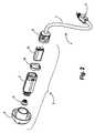
RITE構成要素3の組立図を示す図2に明示されているように,RITE構成要素3はさらに,耳垢ガード19,レシーバ・ハウジング5,レシーバ・シール18およびレシーバ10を備えている。取付具9は,レシーバ・ハウジング5内のレシーバ10を,コネクタ4に接続するために設けられている。 As clearly shown in FIG. 2, which shows an assembly drawing of the RITE component 3, the RITE component 3 further includes an
上述した結合手段8は,RITE構成要素3全体,すなわちレシーバ10の交換を簡単にするために設けられている。同様に,上記取付具9は,レシーバ・ハウジング5から簡単に取外すことができ,レシーバ10を簡単に交換できる。上述のやり方の一つでレシーバを交換するときに,ユーザまたは技術者は目視によって上記レシーバを必ずしも特定できるわけではなく,RTEハウジング構成要素2にレシーバを結合する前にレシーバ・モデルを簡単に識別する必要性が生じる。 The coupling means 8 described above is provided to simplify the replacement of the entire RITE component 3, ie the
以下,この発明の説明に関して用いる用語について,定義しておく。 The terms used in the description of the present invention are defined below.
この発明の目的のために,用語「レシーバ・モデル」は,レシーバのブランドおよび特定ブランドに関連する特定モデルを意味する。ブランドの例としては,たとえば,SonionおよびKnowlesがある。同様に,モデルの例としては,Knowles製のED-26871やSonion製のCI-6697がある。 For the purposes of this invention, the term “receiver model” means a receiver model and a specific model associated with a specific brand. Examples of brands include Sonion and Knowles. Similarly, ED-26871 from Knowles and CI-6697 from Sonion are examples of models.
「上記補聴器を用いてインピーダンスを計測する」(measuring the impedance using said hearing aid)は,計測を制御および実行するためだけに,補聴器に固有の構成要素(components inherent)を用いてレシーバのインピーダンスを計測することを意味する。これらの構成要素については後述の説明の対象とする。 “Measuring the impedance using the hearing aid” measures the impedance of the receiver using components inherent to the hearing aid only to control and execute the measurement. It means to do. These components are the subject of the following description.
この発明の目的のために,用語「レシーバの所定の固有インピーダンス」(predetermined characteristic impedance of a receiver)は,特定のレシーバ・モデルに特有のあらかじめ計測されたインピーダンス値を意味する。この値は,直流(DC)を計測信号として用いて,関連するレシーバ・モデルのそれぞれについて計測される。 For the purposes of this invention, the term “predetermined characteristic impedance of a receiver” means a pre-measured impedance value that is specific to a particular receiver model. This value is measured for each associated receiver model using direct current (DC) as the measurement signal.
この発明の目的のために,用語「実行ユニット」(execution unit)は,コンピュータ・プログラムまたはコンピュータ・プログラム製品の実行可能なコンピュータ・コードを実行することができる,あらゆる適切なユニットを意味する。 For the purposes of this invention, the term “execution unit” means any suitable unit capable of executing the executable computer code of a computer program or computer program product.
この発明は,既存のRITEタイプの補聴器中に存在する標準の電気信号処理回路が,たとえば,冒頭に記載したように,ユーザの耳道の形状に補聴器をフィッティングするために,既に音響インピーダンス計測の実行に適合されていることを前提とするものであり,したがって電気的インピーダンス計測に簡単に適合させることができる。 The present invention has already been developed for acoustic impedance measurement in order for standard electrical signal processing circuitry present in existing RITE type hearing aids to fit the hearing aid into the shape of the user's ear canal, as described at the beginning, for example. It is assumed that it is adapted to the implementation and can therefore be easily adapted to electrical impedance measurements.
図3は,補聴器1における固有の電気信号処理回路の一例を示す回路図を示している。図示する回路は,A/D(アナログ/ディジタル)コンバータ13,論理ユニット14およびメモリ・ユニット15を含む計測ユニット12を備え,スイッチSW2の使用によって,計測ユニット12を,コンデンサ(キャパシタ)17の向こうの(over a capacitor 17 )マイクロフォン11またはレシーバ10のいずれかに接続することができる。コンデンサ17は分極コンデンサまたは電解コンデンサ(a polarized capacitor or an electrolyte)とすることができる。さらにこの回路は,交流(AC)信号発生器16,スイッチSW3,スイッチSW1および抵抗R1を備えている。上記交流信号発生器16は,上記スイッチSW3を介して所定周波数を持つ計測(測定)信号(a measuring signal)を発生することができる。スイッチSW1およびスイッチSW3の使用によって,AC信号発生器16からのAC信号は,スイッチSW1が開放されているときには抵抗R1を通って,スイッチSW1が閉じられているときには直接に,レシーバ10に与えられる。ディジタル信号処理装置(DSP)20および出力段またはD/A(ディジタル/アナログ)コンバータ21が,補聴器に機能性を提供するために設けられている。 FIG. 3 is a circuit diagram showing an example of a specific electric signal processing circuit in the hearing aid 1. The circuit shown includes a measurement unit 12 including an A / D (analog / digital) converter 13, a
好ましい実施例において,この回路を用いることで,スイッチSW1の開放によって上記交流信号発生器16からの上記AC信号が抵抗R1を通ってレシーバ10に与えられたとき,および上記スイッチSW1が閉じられているときにレシーバ10に直接にAC信号が与えられたときに,レシーバ10のインピーダンスがレシーバ負荷を計測するA/Dコンバータ13を用いて計測され,その後,レシーバ負荷における差(the difference)が計算される。得られたレシーバ負荷における差は,次にレシーバ10のインピーダンスの計算に用いることができる。計測ユニット12の論理ユニット14は,計測手順中において,スイッチSW1,SW2およびAC信号発生器16の制御に用いられる。結果として得られるインピーダンス値は,メモリ・ユニット15に記憶させることができる。 In the preferred embodiment, using this circuit, the AC signal from the AC signal generator 16 is applied to the
これに代えて,レシーバ10のインピーダンスを,直流(DC)を計測信号として用いて計測することも可能である。この場合には,計測ユニット12は,ことによるとA/Dコンバータ13に代えて,たとえば電圧計といったDC電圧の計測に適するユニットから構成することができる。 Alternatively, the impedance of the
様々な計測(測定)信号周波数(measuring signal frequencies)について上述した手順を複数回繰返すことによって,複数の異なる計測信号周波数についてレシーバのインピーダンスを計測することも可能であり,この場合には,用いられた計測信号周波数のそれぞれについて一のインピーダンス値を得ることができる。この実現性の意義は,後ほど説明する。 It is also possible to measure the impedance of the receiver for several different measurement signal frequencies by repeating the above procedure several times for various measuring signal frequencies. One impedance value can be obtained for each measured signal frequency. The significance of this feasibility will be explained later.
当業者には明らかであるが,この発明による方法において用いられる計測ユニット12は,上記目的に適するどのような計測ユニットであってもよい。たとえば,この発明の別の実施例においては,用いられる計測ユニットは補聴器フィッティング・システムの計測ユニットとされる。 As will be apparent to those skilled in the art, the measurement unit 12 used in the method according to the invention may be any measurement unit suitable for the above purpose. For example, in another embodiment of the invention, the measurement unit used is the measurement unit of a hearing aid fitting system.
この発明によるレシーバ・モデルの識別は,上述のインピーダンス計測に基づいて実行される。計測されたインピーダンス値と,一または複数の異なるレシーバ・モデルの所定の固有インピーダンスとを比較して,合致するものがあるかどうかを見つけることによっって,計測されたレシーバ10のモデルが決定される。関連するレシーバ・モデル(複数)の所定の固有インピーダンス(複数)は,計測に用いられる計測ユニットのメモリ・ユニット,たとえばデータベース中に記憶させておくことができ,好ましい実施例では,計測ユニット12のメモリ・ユニット15に記憶させておくことができ,上記比較は,計測ユニットの実行ユニット,好ましい実施例では論理ユニット14によって実行することができる。 Identification of the receiver model according to the present invention is performed based on the impedance measurement described above. The model of the measured
冒頭に説明したように,上述の識別は高い確度で実行することができ,与えられた計測信号周波数における計測のときに,レシーバの所定の固有インピーダンスとレシーバ・モデルとの関係を明確に示すことができる。レシーバ・モデルと固有インピーダンスとの関係の一例が,以下の表1に示されている。記載されているインピーダンス値は,一定直流値(a constant DC)を用いたオーミック計測(an ohmic measurement)によって得られたものである。異なるレシーバ・モデルの固有インピーダンスの相違は,高いレベルの確実性のもとで識別可能である程度に十分に大きいことが分かる。 As explained at the beginning, the above identification can be performed with high accuracy and clearly show the relationship between the receiver's specific intrinsic impedance and the receiver model when measuring at a given measurement signal frequency. Can do. An example of the relationship between the receiver model and the intrinsic impedance is shown in Table 1 below. The impedance values described are obtained by an ohmic measurement using a constant DC value (a constant DC). It can be seen that the difference in the intrinsic impedance of the different receiver models is large enough to be distinguished with a high level of certainty.

さらに,一の特定の計測信号周波数についてのレシーバのインピーダンスの計測において,計測されたレシーバについて一の特定の固有インピーダンス値が得られるので,複数の異なる計測信号周波数における上述の実現性は,計測されるレシーバについて複数の固有インピーダンス値によって構成される結果を得ることができるという実現性に通じる。この結果は,計測信号周波数によっては互いに近接しているが,他の周波数では離間している固有インピーダンス値をもつレシーバ・モデルを,はっきりと識別することに用いることができる。 Furthermore, in measuring the impedance of the receiver for one specific measurement signal frequency, one specific characteristic impedance value is obtained for the measured receiver, so that the above-mentioned feasibility at a plurality of different measurement signal frequencies is measured. This leads to a feasibility that a result constituted by a plurality of intrinsic impedance values can be obtained for the receiver. This result can be used to unambiguously identify receiver models with specific impedance values that are close to each other depending on the measurement signal frequency but are separated at other frequencies.
この発明の実施例では,レシーバ・モデルが識別されると,たとえば警告メッセージのようなメッセージが発行されて情報が与えられる。この警告メッセージは,たとえば,潜在的事後調整(a potential subsequent adjustment)が可能であるかどうか,または識別されたレシーバ・モデルは,それが挿入されている補聴器との組合せが非合法(illegal)または未認可(disallowed)であるといったものとすることができる。補聴器それ自体がインピーダンス計測を制御する実施例においては,警告メッセージは,たとえばレシーバと補聴器の組合せが非合法または未認可等であるときに,音または発生する連続音とすることができる。もちろん,他の有用な警告メッセージのタイプも,この発明による方法において使用することができる。 In an embodiment of the invention, when a receiver model is identified, a message such as a warning message is issued to provide information. This warning message may indicate, for example, whether a potential subsequent adjustment is possible, or if the identified receiver model is illegal or illegal in combination with the hearing aid in which it is inserted. It can be said that it is disallowed. In embodiments where the hearing aid itself controls the impedance measurement, the warning message may be a sound or a continuous sound generated, for example, when the receiver and hearing aid combination is illegal or unauthorized. Of course, other useful warning message types can also be used in the method according to the invention.
この発明による方法の他の実施例では,上記インピーダンス計測に基づく所作(措置)(action)をとることができ,たとえば,発行されたメッセージに基づいて,上記補聴器とレシーバの組合せが非合法,未認可等である場合,上記レシーバが取換えられる。この場合,上述したように,この発明による方法では,取換えられたレシーバのモデルの識別が,再度実行される。 In another embodiment of the method according to the invention, an action based on the impedance measurement can be taken, for example, the combination of the hearing aid and the receiver is illegal or not based on the issued message. In case of approval, etc., the receiver is replaced. In this case, as described above, in the method according to the invention, the identification of the replaced receiver model is performed again.
この発明によるさらに他の実施例では,上記インピーダンス計測に基づく所作(措置)をとることができ,たとえば,発行されたメッセージに基づいて,可能である場合に,識別されたレシーバ・モデルに適するように補聴器または補聴器パラメータが調整(調節)される。 In yet another embodiment according to the present invention, an action based on the above impedance measurement can be taken, for example to be suitable for the identified receiver model, if possible based on the issued message. Hearing aid or hearing aid parameters are adjusted (adjusted).
ここで「補聴器パラメータ」とは,補聴器をユーザの個々の必要性にフィットさせるための一般的なあらゆるパラメータを意味する。冒頭で言及したように,このパラメータの例としては,補聴器利得および音響特性に関するパラメータがある。 Here, “hearing aid parameters” means any general parameters for fitting a hearing aid to the individual needs of the user. As mentioned at the beginning, examples of this parameter include parameters related to hearing aid gain and acoustic characteristics.
この発明の好ましい特定の実施例では,上記インピーダンス計測および/または上記調整は,RITEタイプ補聴器1それ自体によって内部的に制御される。上記インピーダンス計測および調整のいずれもが補聴器それ自体によって制御される場合,外部構成要素または装置はこの発明の方法のステップを実行するのに必要とされず,したがってこの実施例は特に簡便である。この実施例において,これはRITEタイプ補聴器1の計測ユニット12によって達成される。 In a preferred specific embodiment of the invention, the impedance measurement and / or the adjustment is controlled internally by the RITE type hearing aid 1 itself. If any of the above impedance measurements and adjustments are controlled by the hearing aid itself, no external components or devices are required to perform the method steps of the present invention, so this embodiment is particularly convenient. In this embodiment, this is achieved by the measuring unit 12 of the RITE type hearing aid 1.
これに代わるこの発明の他の実施例として,上記インピーダンス計測および上記調整を,外部システムにおいて制御するようにしてもよく,特に,補聴器フィッティング・システム,またはコンピュータ・システムにおいて制御するようにしてもよい。この場合,上記レシーバ・モデルの識別および調整はフィッティング手順の一部として実行される。しかしながら,当業者には自明であるが,この発明による方法は,上記目的に適するあらゆるシステムにおいて制御させるようにしてもよい。適合可能なシステムは,一般には実行ユニットおよびメモリ・ユニットを備えた計測ユニットを備えている。ここで,用語「実行ユニット」は,この発明の実施例において,コンピュータ・プログラムまたはコンピュータ・プログラム製品の実行可能なコンピュータ・コードを実行可能な,あらゆる適切なユニットを意味する。このシステムもまた,たとえばA/Dコンバータのような他の構成要素を備えることができる。 As another alternative embodiment of the present invention, the impedance measurement and the adjustment may be controlled by an external system, and particularly by a hearing aid fitting system or a computer system. . In this case, the identification and adjustment of the receiver model is performed as part of the fitting procedure. However, as will be apparent to those skilled in the art, the method according to the present invention may be controlled in any system suitable for the above purpose. A compatible system generally comprises a measurement unit with an execution unit and a memory unit. Here, the term “execution unit” means any suitable unit capable of executing executable computer code of a computer program or computer program product in an embodiment of the present invention. The system can also include other components such as an A / D converter.
一例として記述される好ましい実施例において,上述の実行ユニットは論理ユニット14であり,上述のメモリ・ユニットはメモリ・ユニット15である。 In the preferred embodiment described by way of example, the execution unit described above is a
他の実施例において,上記実行ユニットはこの発明による方法を実行するコンピュータ・システムとすることができる。このコンピュータ・システムは,フィッティング状況(a fitting situation)に適用することができ,この場合には,フィッティングされるべき補聴器も,フィッティング・ルーチンを実行する実行可能なプログラム・コードをも備えたコンピュータ・システムに,接続される。そして,コンピュータ・システム上で実行されるプログラム・コードは,この発明による方法のすべての適切なステップの実行に必要なプログラム部分を含み,少なくとも一の計測信号周波数を用いてレシーバのインピーダンスを計測し,インピーダンス計測に基づいて上記レシーバを複数の所定のレシーバ・モデルの一つとして識別し,メッセージを発行し,補聴器または補聴器パラメータを,識別された特定モデルのレシーバにフィットするように調整し,計測されたインピーダンスを複数のレシーバ・タイプについての所定の固有インピーダンス値と比較する。 In another embodiment, the execution unit may be a computer system that executes the method according to the invention. This computer system can be applied to a fitting situation, in which case the hearing aid to be fitted as well as the computer program with executable program code to execute the fitting routine. Connected to the system. The program code executed on the computer system includes the program parts necessary for the execution of all appropriate steps of the method according to the invention and measures the impedance of the receiver using at least one measurement signal frequency. Identify the receiver as one of several predetermined receiver models based on impedance measurements, issue a message, adjust the hearing aid or hearing aid parameters to fit the identified model receiver, and measure Comparing the measured impedance to a predetermined intrinsic impedance value for a plurality of receiver types.
この発明の実施例による方法は,たとえば補聴器をフィッティングする際にオージオロストによって用いられるパーソナル・コンピュータまたはワークステーションのようなあらゆる適切なデータ処理システムに実装させることができる。この発明による方法は,記述した実施例にしたがう方法を実行する実行プログラム・コードを含むコンピュータ・プログラム中に実装することもできる。クライアント−サーバ環境が用いられる場合に,この発明の実施例は遠隔サーバ・コンピュータを備え,遠隔サーバ・コンピュータはこの発明によるシステムを具現化し,この発明によるコンピュータ・プログラム実行方法をホストする。 The method according to embodiments of the present invention can be implemented in any suitable data processing system, such as a personal computer or workstation used by audio losing when fitting a hearing aid, for example. The method according to the invention can also be implemented in a computer program containing executable program code for performing the method according to the described embodiment. When a client-server environment is used, an embodiment of the present invention comprises a remote server computer, which embodies the system according to the present invention and hosts the computer program execution method according to the present invention.
他の実施例では,上記メモリ・ユニットは,コンピュータ読取可能な記憶媒体のようなコンピュータ・プログラム製品であってもよく,たとえば,フロッピィ・ディスク,メモリ・スティック,CD−ROM,DVD,フラッシュ・メモリ,または他の適切なこの発明によるコンピュータ・プログラムを記憶する記録媒体であってもよい。 In other embodiments, the memory unit may be a computer program product such as a computer readable storage medium, such as a floppy disk, memory stick, CD-ROM, DVD, flash memory. Or any other suitable recording medium for storing a computer program according to the present invention.
さらに他の実施例において,コンピュータ・プログラムは,メモリ・ユニット15のような補聴器のメモリ・ユニット,またはコンピュータ・メモリに記憶され,補聴器それ自体によって,またはCPUのような処理ユニットによって,または他の適切な処理装置またはこの発明による方法を実行するコンピュータによって,実行される。 In still other embodiments, the computer program is stored in a memory unit of a hearing aid, such as
上述した特徴のすべての適切な組合わせは,たとえその組合わせが明示されていなくてもこの発明に属すると考えられる。さらに,上述した好ましい実施例の記載は単に例示にすぎず,当業者であれば,特許請求の範囲から逸脱することなく,多数の変形例を知りうることができることを指摘しておく。 All suitable combinations of the features described above are considered to belong to this invention even if the combination is not explicitly stated. Furthermore, it should be pointed out that the description of the preferred embodiments described above is merely illustrative and that many variations can be known by those skilled in the art without departing from the scope of the claims.
Claims (8)
Translated fromJapanese上記補聴器(1)において上記信号処理装置(20)から出力される処理済信号のための信号経路中にレシーバ(10)を接続し,
上記信号発生器(16)において計測信号を発生し,上記計測信号を,上記処理済信号のための信号経路を通して上記レシーバ(10)に与え,
上記インピーダンスを計測する手段(12)において,上記計測信号に基づく上記レシーバ(10)のレシーバ負荷を得,得られた上記レシーバ負荷を用いて上記補聴器(1) に接続されたレシーバ(10)のインピーダンスを計測し,
上記インピーダンス計測の結果に基づいて上記レシーバ(10)を複数の所定のレシーバ・モデルの一つとして識別し,
上記識別に基づいて,上記補聴器(1)に接続された上記レシーバ(10)の上記識別されたレシーバ・モデルが上記補聴器(1)と未認可の組合せを構成するかどうかを少なくとも判定し,
上記判定結果に基づいて警告メッセージを発行する,
補聴器(1) 中のレシーバ(10) を識別する方法。A hearing aid (1) having a signal processing device (20), a signal generator (16), and means (12) for measuring impedance is prepared.
In the hearing aid (1), the receiver (10) is connected in the signal path for the processed signal output from the signal processing device (20).
The signal generator (16) generates a measurement signal, and the measurement signal is supplied to the receiver (10) through a signal path for the processed signal.
In the means (12) for measuring the impedance, a receiver load of the receiver (10) is obtained based on the measurement signal, and the receiver (10) connected to the hearing aid (1) is obtained using the obtained receiver load. Measure impedance,
Based on the result of the impedance measurement, the receiver (10) is identified as one of a plurality of predetermined receiver models,
Based on the identification, at least determine whether the identified receiver model of the receiver (10) connected to the hearing aid (1) constitutes an unauthorized combination with the hearing aid (1);
Issue warning message based on the above judgment result,
How to identify the receiver (10) in the hearing aid (1).
上記耳内レシーバ・コンポーネントは,上記耳掛け型ハウジング・コンポーネント中の上記信号処理装置(20)から出力される処理済信号のための信号経路中に接続されるレシーバ(10)を含み,
上記信号発生器(16)は計測信号を発生し,上記計測信号を,上記処理済信号のための信号経路を通して上記レシーバ(10)に与えるものであり,
上記インピーダンスを計測する手段(12)は,上記計測信号に基づく上記レシーバ(10)のレシーバ負荷を得,得られた上記レシーバ負荷を用いて上記耳掛け型ハウジング・コンポーネントに接続されている上記耳内レシーバ・コンポーネント中の上記レシーバ(10)のインピーダンスを計測するものであり,
上記耳掛け型ハウジング・コンポーネントはさらに,
複数の所定のレシーバ・モデルのインピーダンス特性を記憶するためのメモリ・ユニット(15),
上記計測されたインピーダンスを上記メモリ・ユニット(15)に記憶されているインピーダンス特性と比較することによって上記レシーバ(10)のレシーバ・モデルを識別する論理ユニット,および
上記識別の結果に基づく判定を実行する手段(14)を備え,
上記判定実行手段による判定は,上記補聴器(1)に接続された上記レシーバ(10)の上記識別されたレシーバ・モデルが上記補聴器(1)と未認可の組合せを構成するかどうかの判定を少なくとも含み,
外部装置に上記判定を通信する手段を備えている,
耳内レシーバ・タイプの補聴器(1) 。An ear-mounted housing component having a signal processor (20), a signal generator (16) and a means (12) for measuring impedance, and an in-ear receiver component
The in-ear receiver component includes a receiver (10) connected in a signal path for a processed signal output from the signal processing device (20) in the ear-mounted housing component;
The signal generator (16) generates a measurement signal and supplies the measurement signal to the receiver (10) through a signal path for the processed signal.
The means for measuring the impedance (12) obtains a receiver load of the receiver (10) based on the measurement signal, and uses the obtained receiver load to connect the ear-mounted housing component. It measures the impedance of the receiver (10) in the receiver component.
The above-mentioned ear-mounted housing component is further
A memory unit (15) for storing impedance characteristics of a plurality of predetermined receiver models,
A logical unit that identifies the receiver model of the receiver (10) by comparing the measured impedance with the impedance characteristic stored in the memory unit (15), and a determination based on the result of the identification Means (14) to
The determination by the determination execution means is at least a determination as to whether the identified receiver model of the receiver (10) connected to the hearing aid (1) constitutes an unauthorized combination with the hearing aid (1). Including
Means for communicating the determination to an external device,
In-ear receiver type hearing aid (1).
請求項2に記載の補聴器。Means (14) for performing a determination based on the impedance measurement result includes means for identifying a plurality of parameters associated with the identified receiver;
The hearing aid according to claim2 .
請求項2に記載の補聴器。The external device includes a computer executing fitting software adapted to provide fitting advice based on the determination;
The hearing aid according to claim2 .
上記補聴器(1)は,上記信号処理装置(20)から出力される処理済信号のための信号経路中に接続されるレシーバ(10)を備え,
上記信号発生器(16)は計測信号を発生し,上記計測信号を,上記処理済信号のための信号経路中に接続されているレシーバ(10)に与えるものであり,
上記インピーダンスを計測する手段(12)は,上記計測信号に基づく上記レシーバ(10)のレシーバ負荷を得,得られた上記レシーバ負荷を用いて上記補聴器(1) に接続されたレシーバ(10)のインピーダンスを計測するものであり,
上記補聴器(1)はさらに,
上記インピーダンス計測結果に基づいて上記レシーバ(10)を複数の所定のレシーバ・モデルの一つとして識別する識別手段,
上記識別に基づいて,上記補聴器に接続された上記レシーバ(10)の上記識別されたレシーバ・モデルが上記補聴器と未認可の組合せを構成するかどうかの判定を少なくとも実行する手段(14),および
上記コンピュータに上記判定を通信する手段を備えている,
補聴器フィッティング・システム。At least one comprising a computer, suitable hearing aid fitting software installed to be executed on the computer, and a signal processing device (20), a signal generator (16) and means for measuring impedance (12) A hearing aid fitting system with a hearing aid (1),
The hearing aid (1) includes a receiver (10) connected in a signal path for a processed signal output from the signal processing device (20).
The signal generator (16) generates a measurement signal and supplies the measurement signal to a receiver (10) connected in a signal path for the processed signal.
The means (12) for measuring the impedance obtains a receiver load of the receiver (10) based on the measurement signal, and uses the obtained receiver load of the receiver (10) connected to the hearing aid (1). Which measures impedance,
The hearing aid (1)
Identification means for identifying the receiver (10) as one of a plurality of predetermined receiver models based on the impedance measurement result;
Means (14) for performing at least a determination based on the identification whether the identified receiver model of the receiver (10) connected to the hearing aid constitutes an unauthorized combination with the hearing aid; and Means for communicating the determination to the computer,
Hearing aid fitting system.
請求項7に記載の補聴器フィッティング・システム。The fitting software installed on the computer includes means for displaying information relating to the impedance of a receiver connected to the hearing aid;
A hearing aid fitting system according to claim7 .
Applications Claiming Priority (1)
| Application Number | Priority Date | Filing Date | Title |
|---|---|---|---|
| PCT/DK2007/050087WO2009006889A1 (en) | 2007-07-10 | 2007-07-10 | Method for identifying a receiver in a hearing aid |
Publications (2)
| Publication Number | Publication Date |
|---|---|
| JP2010531126A JP2010531126A (en) | 2010-09-16 |
| JP5292396B2true JP5292396B2 (en) | 2013-09-18 |
Family
ID=39145395
Family Applications (1)
| Application Number | Title | Priority Date | Filing Date |
|---|---|---|---|
| JP2010513650AActiveJP5292396B2 (en) | 2007-07-10 | 2007-07-10 | Method for identifying a receiver in a hearing aid |
Country Status (8)
| Country | Link |
|---|---|
| US (1) | US8855323B2 (en) |
| EP (1) | EP2177052B1 (en) |
| JP (1) | JP5292396B2 (en) |
| CN (1) | CN101743762A (en) |
| AU (1) | AU2007356359B2 (en) |
| CA (2) | CA2723466C (en) |
| DK (1) | DK2177052T3 (en) |
| WO (1) | WO2009006889A1 (en) |
Families Citing this family (59)
| Publication number | Priority date | Publication date | Assignee | Title |
|---|---|---|---|---|
| US7668325B2 (en) | 2005-05-03 | 2010-02-23 | Earlens Corporation | Hearing system having an open chamber for housing components and reducing the occlusion effect |
| US8401212B2 (en) | 2007-10-12 | 2013-03-19 | Earlens Corporation | Multifunction system and method for integrated hearing and communication with noise cancellation and feedback management |
| US8189829B2 (en)* | 2007-07-26 | 2012-05-29 | Phonak Ag | Resistance-based identification |
| DE102007039452B3 (en) | 2007-08-21 | 2009-06-04 | Siemens Audiologische Technik Gmbh | Automatic handset type detection on hearing aids |
| EP2061274A1 (en) | 2007-11-19 | 2009-05-20 | Oticon A/S | Hearing instrument using receivers with different performance characteristics |
| WO2009155358A1 (en) | 2008-06-17 | 2009-12-23 | Earlens Corporation | Optical electro-mechanical hearing devices with separate power and signal components |
| BRPI0919266A2 (en) | 2008-09-22 | 2017-05-30 | SoundBeam LLC | device and method for transmitting an audio signal to a user, methods for manufacturing a device for transmitting an audio signal to the user, and for providing an audio device for a user, and device and method for transmitting a sound for a user. user having a tympanic membrane |
| DE102009008456B4 (en)* | 2009-02-11 | 2010-11-25 | Siemens Medical Instruments Pte. Ltd. | Automatic hearing recognition for hearing aids |
| EP2280560B1 (en) | 2009-07-03 | 2015-09-09 | Bernafon AG | A hearing aid system comprising a receiver in the ear and a system for identification of the type of receiver |
| CN102687533A (en) | 2009-10-19 | 2012-09-19 | 唯听助听器公司 | Hearing aid system with lost partner functionality |
| EP2378792A1 (en)* | 2010-04-14 | 2011-10-19 | GN Resound A/S | Hearing aid with sound tube |
| EP2656639B1 (en) | 2010-12-20 | 2020-05-13 | Earlens Corporation | Anatomically customized ear canal hearing apparatus |
| USD685912S1 (en)* | 2011-07-01 | 2013-07-09 | Widex A/S | Hearing aid part |
| US9008341B2 (en) | 2011-10-03 | 2015-04-14 | Semiconductor Components Industries, Llc | System and method for identification of a peripheral device |
| USD715447S1 (en)* | 2011-12-15 | 2014-10-14 | Widex A/S | Radio receiver for a hearing aid |
| MX346504B (en)* | 2012-02-24 | 2017-03-22 | Fraunhofer Ges Forschung | Apparatus for providing an audio signal for reproduction by a sound transducer, system, method and computer program. |
| EP2637423A1 (en)* | 2012-03-06 | 2013-09-11 | Oticon A/S | A test device for a speaker module for a listening device |
| EP2744225B1 (en) | 2012-12-17 | 2015-08-26 | Bernafon AG | Hearing instrument and method of identifying an output transducer of a hearing instrument |
| EP2753101A1 (en)* | 2013-01-07 | 2014-07-09 | Oticon A/s | Hearing aid with an in-the-ear component |
| US9426587B2 (en)* | 2013-01-24 | 2016-08-23 | Sonion Nederland B.V. | Electronics in a receiver-in-canal module |
| USD734472S1 (en)* | 2013-03-12 | 2015-07-14 | Gn Resound A/S | Hearing aid |
| USD735339S1 (en)* | 2013-07-02 | 2015-07-28 | Gn Resound A/S | Hearing aid |
| USD734855S1 (en)* | 2013-07-02 | 2015-07-21 | Gn Resound A/S | Hearing aid |
| USD735340S1 (en)* | 2013-12-30 | 2015-07-28 | Gn Resound A/S | Hearing aid |
| US10051392B2 (en) | 2014-02-17 | 2018-08-14 | Gn Hearing A/S | Hearing aid configuration detection |
| DK201470077A1 (en)* | 2014-02-17 | 2015-08-31 | Gn Resound As | Hearing aid configuration detection |
| US10034103B2 (en) | 2014-03-18 | 2018-07-24 | Earlens Corporation | High fidelity and reduced feedback contact hearing apparatus and methods |
| USD724227S1 (en)* | 2014-03-20 | 2015-03-10 | Widex A/S | In ear part for a RITE hearing aid |
| USD724226S1 (en)* | 2014-03-20 | 2015-03-10 | Widex A/S | In ear part for a rite hearing aid |
| US10014842B2 (en)* | 2014-03-28 | 2018-07-03 | Motorola Solutions, Inc. | Method and apparatus for identifying audio accessory through two pin connection in a two way radio |
| CN105208501A (en) | 2014-06-09 | 2015-12-30 | 杜比实验室特许公司 | Method for modeling frequency response characteristic of electro-acoustic transducer |
| DK3169396T3 (en) | 2014-07-14 | 2021-06-28 | Earlens Corp | Sliding bias and peak limitation for optical hearing aids |
| USD762305S1 (en)* | 2014-09-24 | 2016-07-26 | Sonova Ag | Hearing aid |
| JP6322339B2 (en)* | 2014-10-15 | 2018-05-09 | ヴェーデクス・アクティーセルスカプ | Hearing aid system operating method and hearing aid system |
| CN106797520B (en) | 2014-10-15 | 2019-08-13 | 唯听助听器公司 | The method and hearing aid device system of operating hearing aid system |
| US9924276B2 (en) | 2014-11-26 | 2018-03-20 | Earlens Corporation | Adjustable venting for hearing instruments |
| CN107005774B (en)* | 2014-12-17 | 2019-09-06 | 唯听助听器公司 | The method of hearing aid and operating hearing aid system |
| DK3235265T3 (en) | 2014-12-17 | 2019-04-23 | Widex As | PROCEDURE TO OPERATE A HEARING SYSTEM AND HEARING SYSTEM |
| USD797938S1 (en)* | 2015-03-25 | 2017-09-19 | IMHear Corporation | Hearing aid |
| EP3101917B1 (en) | 2015-06-03 | 2017-10-11 | GN Resound A/S | Hearing aid configuration detection |
| US9723415B2 (en)* | 2015-06-19 | 2017-08-01 | Gn Hearing A/S | Performance based in situ optimization of hearing aids |
| US9445204B1 (en) | 2015-09-16 | 2016-09-13 | Semiconductor Components Industries, Llc | Method of forming a semiconductor device and structure therefor |
| US9473861B1 (en) | 2015-09-16 | 2016-10-18 | Semiconductor Components Industries, Llc | Method of forming a semiconductor device and structure therefor |
| DK3888564T3 (en) | 2015-10-02 | 2025-07-14 | Earlens Corp | DEVICE FOR CUSTOMIZED DELIVERY OF MEDICINE IN THE EAR CANAL |
| US10178483B2 (en) | 2015-12-30 | 2019-01-08 | Earlens Corporation | Light based hearing systems, apparatus, and methods |
| US11350226B2 (en) | 2015-12-30 | 2022-05-31 | Earlens Corporation | Charging protocol for rechargeable hearing systems |
| US10492010B2 (en) | 2015-12-30 | 2019-11-26 | Earlens Corporations | Damping in contact hearing systems |
| JP6731654B2 (en)* | 2016-03-25 | 2020-07-29 | パナソニックIpマネジメント株式会社 | Hearing aid adjustment device, hearing aid adjustment method, and hearing aid adjustment program |
| USD837984S1 (en)* | 2016-07-12 | 2019-01-08 | Gn Hearing A/S | Hearing aid |
| USD801536S1 (en)* | 2016-07-12 | 2017-10-31 | Gn Hearing A/S | Hearing aid |
| EP3510796A4 (en) | 2016-09-09 | 2020-04-29 | Earlens Corporation | Contact hearing systems, apparatus and methods |
| WO2018093733A1 (en) | 2016-11-15 | 2018-05-24 | Earlens Corporation | Improved impression procedure |
| WO2019042557A1 (en) | 2017-08-31 | 2019-03-07 | Sonova Ag | A hearing device adapted to perform a self-test and a method for testing a hearing device |
| WO2019173470A1 (en) | 2018-03-07 | 2019-09-12 | Earlens Corporation | Contact hearing device and retention structure materials |
| WO2019199680A1 (en) | 2018-04-09 | 2019-10-17 | Earlens Corporation | Dynamic filter |
| US10409545B1 (en) | 2018-04-17 | 2019-09-10 | Starkey Laboratories, Inc. | Digital identification of devices attached to serial communication cables |
| DE102018209720B3 (en)* | 2018-06-15 | 2019-07-04 | Sivantos Pte. Ltd. | Method for identifying a handset, hearing system and earpiece set |
| EP3706441B1 (en)* | 2019-03-07 | 2025-01-22 | Oticon A/s | A hearing device comprising a sensor configuration detector |
| US11638080B2 (en)* | 2020-06-30 | 2023-04-25 | Gn Hearing A/S | Hearing device assembly |
Family Cites Families (26)
| Publication number | Priority date | Publication date | Assignee | Title |
|---|---|---|---|---|
| JPS62151100A (en) | 1985-12-25 | 1987-07-06 | Matsushita Electric Ind Co Ltd | hearing aid |
| JPS63273072A (en) | 1987-04-30 | 1988-11-10 | Fujitsu Ltd | Plug-in unit identification method |
| DE59008091D1 (en)* | 1990-10-12 | 1995-02-02 | Siemens Ag | Hearing aid with a data storage device. |
| CA2295750A1 (en) | 1997-07-18 | 1999-01-28 | Resound Corporation | Behind the ear hearing aid system |
| TW392416B (en)* | 1997-08-18 | 2000-06-01 | Noise Cancellation Tech | Noise cancellation system for active headsets |
| JPH11162574A (en) | 1997-11-27 | 1999-06-18 | Canon Inc | Plug identification device |
| WO1999009799A2 (en) | 1998-11-24 | 1999-03-04 | Phonak Ag | Hearing aid |
| US7139404B2 (en) | 2001-08-10 | 2006-11-21 | Hear-Wear Technologies, Llc | BTE/CIC auditory device and modular connector system therefor |
| JP4294950B2 (en) | 2001-11-08 | 2009-07-15 | フォーナック アーゲー | HEARING DEVICE, HEARING DEVICE SET, HEARING DEVICE MANUFACTURING METHOD, AND HEARING DEVICE UPDATE METHOD |
| DE10221088A1 (en) | 2002-05-11 | 2003-11-27 | Braun Gmbh | Electronic circuit with at least one input for selecting a state of the electronic circuit |
| US7890284B2 (en)* | 2002-06-24 | 2011-02-15 | Analog Devices, Inc. | Identification system and method for recognizing any one of a number of different types of devices |
| US7142926B2 (en) | 2002-08-30 | 2006-11-28 | Advanced Bionics Corporation | Quick connect earhook system for BTE devices |
| US6651501B1 (en) | 2002-12-30 | 2003-11-25 | Motorola, Inc | Adaptive equalizer for variable length sound tubes utilizing an electrical impedance measurement |
| US7010132B2 (en) | 2003-06-03 | 2006-03-07 | Unitron Hearing Ltd. | Automatic magnetic detection in hearing aids |
| JP2005038492A (en) | 2003-07-18 | 2005-02-10 | Teac Corp | Electronic device mounted component identification method and electronic device capable of identifying mounted components |
| DE10343291B3 (en) | 2003-09-18 | 2005-04-21 | Siemens Audiologische Technik Gmbh | Hearing aid and method for adjusting a hearing aid |
| US7450726B2 (en) | 2004-03-11 | 2008-11-11 | Texas Instruments Incorporated | Headset detector in a device generating audio signals |
| JP2005341413A (en)* | 2004-05-28 | 2005-12-08 | Denso Corp | Vehicle-mounted hands-free device |
| US20050268000A1 (en) | 2004-05-28 | 2005-12-01 | Carlson Mark J | Accessory identifier in an electronic device |
| US7599500B1 (en) | 2004-12-09 | 2009-10-06 | Advanced Bionics, Llc | Processing signals representative of sound based on the identity of an input element |
| DE102005034380B3 (en)* | 2005-07-22 | 2006-12-21 | Siemens Audiologische Technik Gmbh | Hearing aid for auditory canal of e.g. baby, has status report unit to compare signal with reference such that information with report about seating of aid is determined and output device to output information to sending/receiving unit |
| CA2625024C (en)* | 2005-10-17 | 2017-06-13 | Widex A/S | An interchangeable acoustic system for a hearing aid, and a hearing aid |
| US7949144B2 (en)* | 2006-06-12 | 2011-05-24 | Phonak Ag | Method for monitoring a hearing device and hearing device with self-monitoring function |
| DE602006017448D1 (en)* | 2006-08-08 | 2010-11-18 | Phonak Ag | METHOD AND DEVICES RELATED TO HEARING EQUIPMENT, IN PARTICULAR FOR MAINTENANCE OF HEARING EQUIPMENT AND FOR THE PROVISION OF RELATED CONSUMABLES |
| US8180090B2 (en)* | 2007-05-11 | 2012-05-15 | Sony Ericsson Mobile Communications Ab | Headset with exchangeable speaker |
| US8189829B2 (en)* | 2007-07-26 | 2012-05-29 | Phonak Ag | Resistance-based identification |
- 2007
- 2007-07-10JPJP2010513650Apatent/JP5292396B2/enactiveActive
- 2007-07-10AUAU2007356359Apatent/AU2007356359B2/ennot_activeCeased
- 2007-07-10CACA2723466Apatent/CA2723466C/enactiveActive
- 2007-07-10DKDK07764507.5Tpatent/DK2177052T3/enactive
- 2007-07-10EPEP07764507Apatent/EP2177052B1/enactiveActive
- 2007-07-10CACA2691105Apatent/CA2691105A1/enactivePending
- 2007-07-10WOPCT/DK2007/050087patent/WO2009006889A1/enactiveApplication Filing
- 2007-07-10CNCN200780053484Apatent/CN101743762A/enactivePending
- 2010
- 2010-01-06USUS12/683,407patent/US8855323B2/enactiveActive
Also Published As
| Publication number | Publication date |
|---|---|
| US20100111315A1 (en) | 2010-05-06 |
| JP2010531126A (en) | 2010-09-16 |
| AU2007356359A1 (en) | 2009-01-15 |
| EP2177052A1 (en) | 2010-04-21 |
| CA2723466C (en) | 2015-02-17 |
| AU2007356359B2 (en) | 2011-03-31 |
| DK2177052T3 (en) | 2012-08-13 |
| EP2177052B1 (en) | 2012-06-06 |
| WO2009006889A1 (en) | 2009-01-15 |
| CA2723466A1 (en) | 2009-01-15 |
| CA2691105A1 (en) | 2009-01-15 |
| CN101743762A (en) | 2010-06-16 |
| US8855323B2 (en) | 2014-10-07 |
Similar Documents
| Publication | Publication Date | Title |
|---|---|---|
| JP5292396B2 (en) | Method for identifying a receiver in a hearing aid | |
| US9992582B2 (en) | Method of operating a hearing aid system and a hearing aid system | |
| US9226082B2 (en) | Hearing aid with means for estimating the ear plug fitting | |
| DK3235265T3 (en) | PROCEDURE TO OPERATE A HEARING SYSTEM AND HEARING SYSTEM | |
| EP3808102A1 (en) | Method of testing microphone performance of a hearing aid system and a hearing aid system | |
| US20170350925A1 (en) | Hearing aid and a method of operating a hearing aid system | |
| CN107079228B (en) | Method of operating a hearing aid system and hearing aid system | |
| US11245992B2 (en) | Method of testing microphone performance of a hearing aid system and a hearing aid system | |
| US11622203B2 (en) | Method of fitting a hearing aid system and a hearing aid system | |
| US11689866B2 (en) | Hearing device adapted to perform a self-test and a method for testing a hearing device | |
| US11540070B2 (en) | Method of fine tuning a hearing aid system and a hearing aid system |
Legal Events
| Date | Code | Title | Description |
|---|---|---|---|
| A977 | Report on retrieval | Free format text:JAPANESE INTERMEDIATE CODE: A971007 Effective date:20111130 | |
| A131 | Notification of reasons for refusal | Free format text:JAPANESE INTERMEDIATE CODE: A131 Effective date:20111213 | |
| A521 | Request for written amendment filed | Free format text:JAPANESE INTERMEDIATE CODE: A523 Effective date:20120307 | |
| A131 | Notification of reasons for refusal | Free format text:JAPANESE INTERMEDIATE CODE: A131 Effective date:20120403 | |
| A521 | Request for written amendment filed | Free format text:JAPANESE INTERMEDIATE CODE: A523 Effective date:20120628 | |
| A131 | Notification of reasons for refusal | Free format text:JAPANESE INTERMEDIATE CODE: A131 Effective date:20130108 | |
| A521 | Request for written amendment filed | Free format text:JAPANESE INTERMEDIATE CODE: A523 Effective date:20130404 | |
| TRDD | Decision of grant or rejection written | ||
| A01 | Written decision to grant a patent or to grant a registration (utility model) | Free format text:JAPANESE INTERMEDIATE CODE: A01 Effective date:20130604 | |
| A61 | First payment of annual fees (during grant procedure) | Free format text:JAPANESE INTERMEDIATE CODE: A61 Effective date:20130610 | |
| R150 | Certificate of patent or registration of utility model | Ref document number:5292396 Country of ref document:JP Free format text:JAPANESE INTERMEDIATE CODE: R150 | |
| R250 | Receipt of annual fees | Free format text:JAPANESE INTERMEDIATE CODE: R250 | |
| R250 | Receipt of annual fees | Free format text:JAPANESE INTERMEDIATE CODE: R250 | |
| R250 | Receipt of annual fees | Free format text:JAPANESE INTERMEDIATE CODE: R250 | |
| R250 | Receipt of annual fees | Free format text:JAPANESE INTERMEDIATE CODE: R250 | |
| R250 | Receipt of annual fees | Free format text:JAPANESE INTERMEDIATE CODE: R250 | |
| R250 | Receipt of annual fees | Free format text:JAPANESE INTERMEDIATE CODE: R250 | |
| R250 | Receipt of annual fees | Free format text:JAPANESE INTERMEDIATE CODE: R250 | |
| R250 | Receipt of annual fees | Free format text:JAPANESE INTERMEDIATE CODE: R250 | |
| R250 | Receipt of annual fees | Free format text:JAPANESE INTERMEDIATE CODE: R250 |