JP5291811B2 - Secondary battery manufacturing method and manufacturing apparatus - Google Patents
Secondary battery manufacturing method and manufacturing apparatusDownload PDFInfo
- Publication number
- JP5291811B2 JP5291811B2JP2012003106AJP2012003106AJP5291811B2JP 5291811 B2JP5291811 B2JP 5291811B2JP 2012003106 AJP2012003106 AJP 2012003106AJP 2012003106 AJP2012003106 AJP 2012003106AJP 5291811 B2JP5291811 B2JP 5291811B2
- Authority
- JP
- Japan
- Prior art keywords
- electrode plate
- positive electrode
- continuous separator
- separator
- negative electrode
- Prior art date
- Legal status (The legal status is an assumption and is not a legal conclusion. Google has not performed a legal analysis and makes no representation as to the accuracy of the status listed.)
- Expired - Fee Related
Links
- 238000004519manufacturing processMethods0.000titleclaimsdescription36
- 239000000853adhesiveSubstances0.000claimsdescription26
- 230000001070adhesive effectEffects0.000claimsdescription26
- 238000002844meltingMethods0.000claimsdescription7
- 230000008018meltingEffects0.000claimsdescription7
- 238000010438heat treatmentMethods0.000claimsdescription6
- 230000002093peripheral effectEffects0.000claimsdescription6
- 238000000638solvent extractionMethods0.000claimsdescription5
- 238000003860storageMethods0.000claimsdescription2
- 230000032258transportEffects0.000description10
- WHXSMMKQMYFTQS-UHFFFAOYSA-NLithiumChemical compound[Li]WHXSMMKQMYFTQS-UHFFFAOYSA-N0.000description6
- 229910052744lithiumInorganic materials0.000description6
- 238000000034methodMethods0.000description5
- 239000007773negative electrode materialSubstances0.000description5
- 239000007774positive electrode materialSubstances0.000description5
- 238000004880explosionMethods0.000description3
- 238000013459approachMethods0.000description2
- 238000005520cutting processMethods0.000description2
- 238000006073displacement reactionMethods0.000description2
- 238000004080punchingMethods0.000description2
- 238000003466weldingMethods0.000description2
- 239000011248coating agentSubstances0.000description1
- 238000000576coating methodMethods0.000description1
- 238000010924continuous productionMethods0.000description1
- 230000000694effectsEffects0.000description1
- 238000003825pressingMethods0.000description1
Images


Classifications
- Y—GENERAL TAGGING OF NEW TECHNOLOGICAL DEVELOPMENTS; GENERAL TAGGING OF CROSS-SECTIONAL TECHNOLOGIES SPANNING OVER SEVERAL SECTIONS OF THE IPC; TECHNICAL SUBJECTS COVERED BY FORMER USPC CROSS-REFERENCE ART COLLECTIONS [XRACs] AND DIGESTS
- Y02—TECHNOLOGIES OR APPLICATIONS FOR MITIGATION OR ADAPTATION AGAINST CLIMATE CHANGE
- Y02E—REDUCTION OF GREENHOUSE GAS [GHG] EMISSIONS, RELATED TO ENERGY GENERATION, TRANSMISSION OR DISTRIBUTION
- Y02E60/00—Enabling technologies; Technologies with a potential or indirect contribution to GHG emissions mitigation
- Y02E60/10—Energy storage using batteries
- Y—GENERAL TAGGING OF NEW TECHNOLOGICAL DEVELOPMENTS; GENERAL TAGGING OF CROSS-SECTIONAL TECHNOLOGIES SPANNING OVER SEVERAL SECTIONS OF THE IPC; TECHNICAL SUBJECTS COVERED BY FORMER USPC CROSS-REFERENCE ART COLLECTIONS [XRACs] AND DIGESTS
- Y02—TECHNOLOGIES OR APPLICATIONS FOR MITIGATION OR ADAPTATION AGAINST CLIMATE CHANGE
- Y02P—CLIMATE CHANGE MITIGATION TECHNOLOGIES IN THE PRODUCTION OR PROCESSING OF GOODS
- Y02P70/00—Climate change mitigation technologies in the production process for final industrial or consumer products
- Y02P70/50—Manufacturing or production processes characterised by the final manufactured product
Landscapes
- Secondary Cells (AREA)
Description
Translated fromJapanese本発明は、枚葉状の正極板と負極板との間にシート状のセパレータを介在させて積層を形成するリチウム2次電池の製造方法と製造装置に関するものである。 The present invention relates to a method and an apparatus for manufacturing a lithium secondary battery in which a sheet-like separator is interposed between a sheet-like positive electrode plate and a negative electrode plate to form a stack.
正極板と負極板の間にセパレータを介在させて2次電池を製造する製造装置として、特許文献1のような製造装置が知られている。 As a manufacturing apparatus for manufacturing a secondary battery by interposing a separator between a positive electrode plate and a negative electrode plate, a manufacturing apparatus as in Patent Document 1 is known.
特許文献1の製造装置は、図4に示すように、セパレータを供給するセパレータ供給部1と、セパレータを引き出すグリップチャック11と、正極板と負極板を供給する正極板供給機構30と負極板供給機構31と、回転チャック機構45とを備えている。 As shown in FIG. 4, the manufacturing apparatus of Patent Document 1 includes a separator supply unit 1 that supplies a separator, a grip chuck 11 that pulls out the separator, a positive electrode plate supply mechanism 30 that supplies a positive electrode plate and a negative electrode plate, and a negative electrode plate supply. A
まず、グリップチャック11がセパレータをセパレータ供給部1から所定量引き出す。次に、セパレータを挟んで対向位置に配置されている正極板供給機構30と負極板供給機構31が、引き出されたセパレータに、正極板と負極板を供給配置する。次に、回転チャック機構45が正極板と負極板をクランプし、クランプした状態で半回転する。次に、回転チャック機構の半回転にあわせて、グリップチャック11がセパレータ供給部側に戻る。次に、正極板供給機構30と負極板供給機構31が、セパレータで挟まれた正極板と負極板の外側に、さらに正極板と負極板を供給配置する。次に、回転チャック機構45が、積層された正極板と負極板をクランプした状態で半回転する。回転チャック機構45が、半回転することで2層目を形成する。次に、回転チャック機構45の半回転にあわせて、グリップチャック11がセパレータ供給側に戻る。以後、グリップチャック11が所定の高さ(正極板供給機構および負極板供給機構の高さ)に戻るまで同様の動作を繰り返す。グリップチャック11が所定の高さに戻ると、カッタがセパレータ供給部側のセパレータを切断し、グリップチャック11がセパレータを開放する。次に、回転チャック機構が積層された正極板と負極板を次の工程に搬送する。このように、特許文献1の製造装置は、セパレータに正極板と負極板を供給配置し、クランプさせた正極板と負極板を回転チャック機構45で半回転しながらリチウム2次電池を製造している。 First, the grip chuck 11 pulls out the separator from the separator supply unit 1 by a predetermined amount. Next, the positive electrode plate supply mechanism 30 and the negative electrode
特許文献1の装置では、セパレータの引き出された長さ分だけ正極板と負極板が折り重ねられる構成となっている。大容量のリチウム2次電池のように、セパレータに折り重ねられる正極板と負極板の枚数が増えると、このような装置では対応できなくなっている。 The apparatus of Patent Document 1 is configured such that the positive electrode plate and the negative electrode plate are folded by the length of the separator drawn out. Such a device cannot cope with the increase in the number of positive and negative electrode plates folded on the separator as in a large capacity lithium secondary battery.
また、正極板と負極板はセパレータに対して固定されていないので搬送時等に積層した位置からずれてしまう問題もある。電極の位置ズレは、短絡事故により短時間に大電流が電極間に流れ爆発、発火事故などが発生する危険性がある。 Moreover, since the positive electrode plate and the negative electrode plate are not fixed with respect to the separator, there is a problem that the positive electrode plate and the negative electrode plate are displaced from the stacked positions during transportation. There is a risk that displacement of the electrodes may cause an explosion or ignition accident due to a large current flowing between the electrodes in a short time due to a short circuit accident.
本発明は、大容量のリチウム2次電池の製造に対応でき、従来の製造装置よりも生産性が向上したリチウム2次電池の製造方法と製造装置を提供することを目的としている。 An object of the present invention is to provide a method and an apparatus for manufacturing a lithium secondary battery that can cope with the manufacture of a large-capacity lithium secondary battery and that has improved productivity over conventional manufacturing apparatuses.
上記の課題を達成するために、請求項1に記載の2次電池製造方法は、
正極板の仕切りに用いられる連続セパレータに、複数の正極板を所定の間隔を保持して配置し、前記正極板に設けられたタブが前記連続セパレータの外側になるように配置し、
他方の正極板の仕切りに用いられる連続セパレータを、前記正極板が配置された連続セパレータに重ね合わせて、
前記正極板の周囲の連続セパレータ同士を
加熱溶融により貼り合わせて接着し、
裏面に接着剤の塗布された負極板を前記連続セパレータの外周面で正極板の表面および裏面に、前記連続セパレータを介して貼り付けた後、次に送られた正極板の表面および裏面には負極板を貼り付けずに、その次に送られた正極板の表面および裏面に、前記連続セパレータを介して貼り付けて、
正極板と負極板が連続セパレータを介して交互に重なり合うように積層状に収納することを特徴とする2次電池製造方法である。In order to achieve the above object, a method for manufacturing a secondary battery according to claim 1 comprises:
In the continuous separator used for partitioning the positive electrode plate, a plurality of positive electrode plates are arranged while maintaining a predetermined interval, and the tab provided on the positive electrode plate is arranged outside the continuous separator,
Superimposing the continuous separator used for partitioning the other positive electrode plate on the continuous separator on which the positive electrode plate is arranged,
Bonding the continuous separators around the positive electrode plate together by heat melting,
After the negative electrode plate with the adhesive applied to the back surface is pasted to the front and back surfaces of the positive electrode plate on the outer peripheral surface of the continuous separator via the continuous separator, the front and back surfaces of the positive electrode plate sent next Without pasting the negative electrode plate, pasted to the front and back surfaces of the positive electrode plate sent next through the continuous separator,
The secondary battery manufacturing method is characterized in that the positive electrode plate and the negative electrode plate are housed in a stacked form so as to alternately overlap with each other via a continuous separator.
請求項2に記載の2次電池製造装置は、
正極板を挟み込む正極板の下側の連続セパレータと、正極板の上側に位置する他方の連続セパレータと、
前記連続セパレータに正極板を所定の間隔を保持し、正極板に設けられたタブを連続セパレータの外側になるように配置する移載ハンドと、
連続セパレータと正極板と他方の連続セパレータとを重ね合わせるニップロールと、
ニップロールから送り出された連続セパレータの端部と正極板毎の間隙を加熱溶融させるヒータと、
連続セパレータのヒータによる加熱溶融と、連続セパレータへの正極板の配置とを連動させて連続セパレータを間欠移動させる搬送コンベアと、
他方の電極板である負極板の裏面に接着剤を塗布する接着剤塗布ノズルと、
裏面に接着剤の塗布された負極板を前記連続セパレータの外周面で正極板の表面および裏面に、前記連続セパレータを介して貼り付けた後、次に送られた正極板の表面および裏面には負極板を貼り付けずに、その次に送られた正極板の表面および裏面に、前記連続セパレータを介して貼り付ける他方の移載ハンドと、
前記連続セパレータを正極板と負極板が前記連続セパレータを介して交互に重なり合うように折り込むスイング機構と、
折り込まれた連続セパレータを積層状に収納する収納箱とからなる2次電池製造装置である。The secondary battery manufacturing apparatus according to claim 2 comprises:
A continuous separator on the lower side of the positive electrode plate sandwiching the positive electrode plate, the other continuous separator located on the upper side of the positive electrode plate,
A transfer hand that holds the positive electrode plate at a predetermined interval on the continuous separator and arranges tabs provided on the positive electrode plate to be outside the continuous separator;
A nip roll for superimposing the continuous separator, the positive electrode plate and the other continuous separator;
A heater for heating and melting the end of the continuous separator fed from the nip roll and the gap for each positive electrode plate;
A transport conveyor that intermittently moves the continuous separator in conjunction with the heating and melting by the heater of the continuous separator and the arrangement of the positive electrode plate on the continuous separator;
An adhesive application nozzle for applying an adhesive to the back surface of the negative electrode plate which is the other electrode plate;
After the negative electrode plate with the adhesive applied to the back surface is pasted to the front and back surfaces of the positive electrode plate on the outer peripheral surface of the continuous separator via the continuous separator, the front and back surfaces of the positive electrode plate sent next Without attaching the negative electrode plate, the other transfer hand that is attached to the front and back surfaces of the positive electrode plate sent next through the continuous separator,
A swing mechanism for folding the continuous separator so that the positive electrode plate and the negative electrode plate alternately overlap with each other through the continuous separator;
It is a secondary battery manufacturing apparatus which consists of a storage box which stores the folded continuous separator in a laminated form.
請求項1に記載の発明によれば、電極板の周囲を連続セパレータの接着により取り囲んでいるので、電極板の位置ズレを防止することができる。そのため、電極板の位置ズレによる短絡事故や爆発・発火事故などを回避することができる。さらに、セパレータが連続セパレータで構成されており、電極板毎に連続セパレータを折り込んで積層タイプの2次電池を構成することができるので、電極板の枚数に制限なく大容量の2次電池の製造に対応することができる。 According to invention of Claim 1, since the circumference | surroundings of the electrode plate are surrounded by adhesion | attachment of the continuous separator, the position shift of an electrode plate can be prevented. Therefore, it is possible to avoid a short circuit accident or an explosion / ignition accident due to the displacement of the electrode plate. Furthermore, since the separator is constituted by a continuous separator, and a laminated type secondary battery can be formed by folding the continuous separator for each electrode plate, the production of a large-capacity secondary battery is not limited by the number of electrode plates. It can correspond to.
さらに、連続セパレータを介して正極板と負極板を配置し、負極板を連続セパレータに接着しているので電極の積層状態においてコンパクトな2次電池を製造することができる。また、シート状の連続セパレータで連続的に積層することが出来るので大容量の2次電池の製造に対応することが出来る。 Furthermore, since the positive electrode plate and the negative electrode plate are arranged via the continuous separator and the negative electrode plate is bonded to the continuous separator, a compact secondary battery can be manufactured in a stacked state of the electrodes. Moreover, since it can laminate | stack continuously with a sheet-like continuous separator, it can respond to manufacture of a high capacity | capacitance secondary battery.
請求項2に記載の発明によれば、連続セパレータの電極板の周囲の接着と、連続セパレータへの電極板の配置を連動して搬送コンベアを間欠運転するので、大容量の2次電池を効率よく製造することができる。また、電極板の周囲の連続セパレータが接着さるので電極板同士の接触を防止することができる。 According to the invention described in claim 2, since the conveyance conveyor is intermittently operated in conjunction with the adhesion around the electrode plate of the continuous separator and the arrangement of the electrode plate on the continuous separator, a large capacity secondary battery can be efficiently used. Can be manufactured well. Further, since the continuous separator around the electrode plates is adhered, the contact between the electrode plates can be prevented.
さらに、接着剤を用いて負極板を連続セパレータに貼り付けているので、正極板と負極板の両方の周囲を連続セパレータで接着しなくても正極板のみの周囲の連続セパレータを接着するだけで効率よく2次電池を製造することができる。 Furthermore, since the negative electrode plate is attached to the continuous separator using an adhesive, it is only necessary to bond the continuous separator around the positive electrode plate without adhering the periphery of both the positive electrode plate and the negative electrode plate with the continuous separator. A secondary battery can be manufactured efficiently.
<実施の形態1>
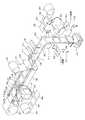
次に本発明のリチウム2次電池製造装置(以後、2次電池製造装置と称する)の実施の形態1を図面を参照して説明する。図1は2次電池製造装置の各要部の配置を示す概略斜視図である。まず、図1に基づいて本発明の2次電池製造装置の概略構成を説明する。なお、2次電池製造装置で用いる正極板および負極板の連続セパレータSを図面の説明上、上セパレータ100と下セパレータ101に区別して記載する。また、電極板PNを正極板108と負極板109に区別して記載する。上セパレータ100は、正極板108および負極板109に対して上側に配置される連続セパレータSを示し、下セパレータ101は、下側に配置される連続セパレータSを示す。連続セパレータSの表面には、接着剤が塗布されており、加熱により接着剤が溶融し連続セパレータS同士が接着されるようになっている。<Embodiment 1>
Next, a first embodiment of a lithium secondary battery manufacturing apparatus (hereinafter referred to as a secondary battery manufacturing apparatus) according to the present invention will be described with reference to the drawings. FIG. 1 is a schematic perspective view showing an arrangement of each main part of the secondary battery manufacturing apparatus. First, a schematic configuration of the secondary battery manufacturing apparatus of the present invention will be described with reference to FIG. In addition, the continuous separator S of the positive electrode plate and the negative electrode plate used in the secondary battery manufacturing apparatus is described by distinguishing between the
2次電池製造装置は、上セパレータ100が送り出される上セパレータ巻出部102と、下セパレータ101が送り出される下セパレータ巻出部103と、送り出された上セパレータ100および下セパレータ101を把持して所定の長さを引き出すニップロール104と、2次電池の積層部105と、ロール状の正極材106および負極材107と、枚葉状の正極板108および負極板109と、正極板108および負極板109を搬送コンベア110上の下セパレータ101に載置する移載ハンド112と、載置された正極板108と負極板109を搬送する搬送コンベア110とを備えている。 The secondary battery manufacturing apparatus grips the upper
正極板108と負極板109は、ロール状の正極材106および負極材107から引き出された電極板を、図示していない打ち抜き装置により所定の大きさに切断して形成される。なお、正極板108および負極板109にはタブ111が形成されるように所定の大きさに切断される。切断された正極板108および負極板109は移載ハンド112の近傍に供給される。 The
移載ハンド112はZ軸回りに回転させる支持部113と、この支持部113に支持されたアーム114と、アーム114の先端側に取り付けられた正極板108および負極板109を吸着する吸着部115とを備えている。正極板108用、負極板109用各々専用に設置された移載ハンド112は、吸着部115で正極板108と負極板109を同時に吸着して下セパレータ101に正極板108と負極板109が隣り合うように配置する。配置の際、下セパレータ101の進行方向に対して所定間隔を保つように、かつ下セパレータ101の端部から所定間隔を保つように配置する。さらに、正極板108と負極板109に設けられたタブ111は、下セパレータ101の外側になるように配置する。 The
下セパレータ101は、ロール状の下セパレータ巻出部103より送り出され搬送コンベア110上を通り、ニップロール104を経由してセパレータ同士の貼り合わせが行われた後、積層部105に積層される。搬送コンベア110上において、正極板108および負極板109が所定位置に配置されると、搬送コンベア110の端部に備えられているサポート部材116が待機位置から90度旋回し、正極板108および負極板109を押さえ、搬送中の位置ズレの防止を行うようになっている。なお、サポート部材116の待機位置側は、搬送コンベア110の進行方向と平行で正極板108と負極板109の配置される位置に干渉しない位置とする。また、サポート部材116は、個々の正極板108および負極板109を搬送コンベア110の進行方向に対して左右に少なくとも2カ所で支えることができるように、搬送コンベア110の端部に複数個が備えられている。搬送コンベア110は、正極板108および負極板109の移載時は停止し、サポート部材116が動作するとニップロール104方向に所定の長さ移動し、間欠運転を行うようになっている。 The
なお、サポート部材116を備える変わりに、移載された正極板108と負極板109を搬送コンベア110上に固定的に保持することができるマグネットコンベア型の搬送コンベア110を用いても良い。 Instead of providing the
正極板108または負極板109が搬送コンベア110により搬送され、ニップロール104に近づくと、サポート部材116が90度旋回し待機位置側に戻る。そして、正極板108または負極板109が、上セパレータ巻出部102から送り出された上セパレータ100と、下セパレータ101に挟み込まれた状態でニップロール104に挟み込まれて重ねられるようになっている。以後、ニップロール104から送り出された上セパレータ100および下セパレータ101を連続セパレータSと呼び、正極板108および負極板109について電極板PNの記載も用いる。 When the
ニップロール104から送り出された連続セパレータSは、ロールヒータ117および2本の棒ヒータ118によって表面が加熱され接着剤が溶融し連続セパレータS同士が接着される。図2に連続セパレータSと電極板PN(正極板108および負極板109)と接着領域を示す。電極板PNは、連続セパレータSのほぼ中央に配置されている。ロールヒータ117は、円筒状のヒータで円筒の外周面が、電極板PNの進行方向で図2の接着領域Aを走行するようになっている。接着領域Aは、電極板PNの周囲で連続セパレータSの端との間の領域となっている。なお、図2において、袋状領域Cの中に収納された電極板PNを点線で示した。 The surface of the continuous separator S sent out from the
次に、接着領域Aが接着されると、2本の棒ヒータ118が下降し図2の接着領域Bを接着する。接着領域Bは連続セパレータSの電極板PN毎の間隔の領域となっている。そして、2本の棒ヒータ118は、電極板PNの間隔と同じ間隔で配置されている。これにより、連続セパレータSの袋状領域Cが形成され、袋状領域Cの中に一枚づつ電極板PNが収納されるようになる。また、タブ111は、袋状領域Cから外部に露出するように形成される。従って、電極板PNの周囲が接着され電極板PNの位置ズレや正極板108と負極板109のショートを防止できるようになる。 Next, when the bonding area A is bonded, the two
周囲が接着された電極板PNは送りロール119に送られ、その後、スイング機構120のより積層部105に正極板108と負極板109が連続セパレータSを介してジグザグ状に積み重ねられる。所定の厚さに積み重ねられると、スイング機構120の出口部に備えられているカッタによって連続セパレータSが切断され、積層体である2次電池の製造が完了する。次に、積層部105に形成された2次電池が次工程に搬送される。なお、図2において積層部105内の積層状態を示すため、積層部105は1点鎖線にて示した。 The electrode plate PN to which the periphery is bonded is sent to the
このように、実施の形態1の2次電池製造装置は、正極板108と負極板109は袋状領域Cに収納されているので搬送時等に積層した位置からずれることがない。そのため、電極板PNの位置ズレ、短絡事故による爆発、発火事故などを回避することができる。さらに、電極板の仕切りに用いられるセパレータが連続セパレータSで構成されており、電極板PN毎に連続セパレータSを折り込んで積層タイプの2次電池を構成することができるので、電極板の枚数に制限なく大容量の2次電池の製造に対応することができる。また、移載ハンド112で正極板108と負極板109を移載するので連続セパレータSに精度よく配置し連続性の高い生産に効率よく対応できる。 Thus, in the secondary battery manufacturing apparatus of the first embodiment, since the
上記実施の形態1では、ロールヒータ117および2本の棒ヒータ118を用いて連続セパレータSを加熱溶融して接着していたが、加熱溶融に限らず超音波溶接を用いることもできる。 In the first embodiment, the continuous separator S is heated and melted and bonded using the
<実施の形態2>
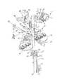
次に、本発明の実施の形態2について、図3を用いて説明する。図3の符号において実施の形態1と同じ構成部品については同じ符号を用いる。<Embodiment 2>
Next, Embodiment 2 of the present invention will be described with reference to FIG. In FIG. 3, the same reference numerals are used for the same components as those in the first embodiment.
図3に示す2次電池製造装置は、上セパレータ100が送り出される上セパレータ巻出部102と、下セパレータ101が送り出される下セパレータ巻出部103と、送り出された上セパレータ100および下セパレータ101を把持して所定の長さを引き出すニップロール104と、2次電池の積層部105と、ロール状の正極材106および負極材107と、枚葉状の正極板108および負極板109と、正極板108を搬送コンベア110上の下セパレータ101に載置する移載ハンド112と、載置された正極板108を搬送する搬送コンベア110と、負極板109の裏面に接着剤121を塗布する接着剤塗布ノズル122と、負極板109を接着剤121の塗布位置と接着剤121の塗布された負極板109を移載する移載ハンド123とを備えている。 The secondary battery manufacturing apparatus shown in FIG. 3 includes an upper
正極板108と負極板109は、ロール状の正極材106および負極材107から引き出された電極板を、図示していない打ち抜き装置により所定の大きさに切断して形成される。なお、正極板108および負極板109にはタブ111が形成されるように所定の大きさに切断される。切断された正極板108は搬送コンベア110の横に設置された移載ハンド112の近傍に供給される。負極板109は、送りロール119の下方に設置された移載ハンド123の近傍に供給される。 The
移載ハンド112はZ軸回りに回転させる支持部113と、この支持部113に支持されたアーム114と、アームの先端側に取り付けられた正極板108を吸着する吸着部115とを備えている。移載ハンド112は、吸着部115を用いて正極板108を吸着し、正極板108を移載コンベア110上の下セパレータ101に所定の間隔で移載する様になっている。 The
下セパレータ101は、ロール状の下セパレータ巻出部103より送り出され搬送コンベア110上を通り水平方向に移動した後、ニップロール104を経由して下降方向に移動し、積層部105に積層される。搬送コンベア110上において、正極板108が所定位置に配置されると、搬送コンベア110の端部に備えられているサポート部材116が待機位置から90度旋回し、正極板108を押さえ、搬送中の位置ズレの防止を行うようになっている。なお、サポート部材116の待機位置側は、搬送コンベア110の進行方向と平行で正極板108の配置される位置に干渉しない位置とする。また、サポート部材116は、個々の正極板108を搬送コンベア110の進行方向に対して左右に少なくとも2カ所で支えることができるように、搬送コンベア110の端部に複数個が備えられている。搬送コンベア110は、正極板108の移載時は停止し、サポート部材116が動作するとニップロール104方向に所定の長さ移動し、間欠運転を行うようになっている。 The
正極板108が搬送コンベア110により搬送され、ニップロール104に近づくと、サポート部材116が90度旋回し待機位置側に戻る。そして、正極板108が、上セパレータ巻出部102から送り出された上セパレータ100と、下セパレータ101に挟み込まれた状態でニップロール104に挟み込まれて重ねられるようになっている。以後、ニップロール104から送り出された上セパレータ100および下セパレータ101を連続セパレータSと呼ぶ。 When the
ニップロール104から送り出された連続セパレータSは、ロールヒータ117および2本の棒ヒータ118によって表面が加熱され接着剤が溶融し連続セパレータS同士が接着される。実施の形態1と同様に、ロールヒータ117が接着領域Aを加熱し溶着し、2本の棒ヒータ118が連続セパレータSの接着領域Bを加熱し溶着する。これにより、連続セパレータSに袋状領域Cが形成され、袋状領域Cの中に一枚づつ正極板108が収納されるようになる。また、タブ111は、袋状領域Cから外部に露出するように形成される。なお、図3において、袋状領域Cの中に収納された正極板108を点線で示した。 The surface of the continuous separator S sent out from the
周囲が接着された連続セパレータSは送りロール119に送られ、積層部105側に下降する。次に、送りロール119の下方に供給された負極板109が、移載ハンド123により、連続セパレータSの左右に配置される。次に、負極板109の下面に、接着剤塗布ノズル122より接着剤121が塗布される。接着剤塗布ノズル122は負極板109の下方に備えられており、負極板109が連続セパレータSの左右に配置される毎に上昇し接着剤121の塗布を行った後、下降し次の負極板109の配置を待機するようになっている。接着剤塗布ノズル122は、下降している連続セパレータSの両側に備えられている。次に、移載ハンド123が、連続セパレータSの外周面で正極板108の表面および裏面に連続セパレータSを介して負極板109を貼り付ける。これにより、負極板109、連続セパレータS、正極板108、連続セパレータS、負極板109の順に重ねられることになる。負極板109の貼付は、正極板108の一つ飛び毎に行われる。(正極板108に対して両側に負極板109を貼り付けた後、次に送られた正極板108の両側には負極板109を貼り付けずに、その次の正極板108の両側に負極板109を貼り付ける。)なお、図3において、接着剤121の負極板109の裏面への塗布状態を点線にて示した。 The continuous separator S to which the periphery is bonded is sent to the
次に、重ねられた正極板108および負極板109が、スイング機構120のより積層部105に連続セパレータSを介してジグザグ状に積み重ねられる。所定の厚さに積み重ねられると、スイング機構120の出口部に備えられているカッタによって上セパレータ100および下セパレータ101が切断され、積層体である2次電池の製造が完了する。次に、積層部105に形成された2次電池が次工程に搬送される。なお、図3において積層部105内の積層状態を示すため、積層部105は1点鎖線にて示した。 Next, the stacked
このように、実施の形態2の2次電池製造装置は、正極板108が袋状領域Cに収納されているので搬送時等に積層した位置からずれることがない。また、正極板108と負極板109が一枚の連続セパレータSで仕切られているので、コンパクトに2次電池を形成することができる。また、シート状の連続セパレータSで連続的に積層することが出来るので大容量の2次電池の製造に対応することが出来る。さらに、接着剤121を用いて負極板109を連続セパレータSに貼り付けているので、正極板108と負極板109の両方の周囲を連続セパレータSで接着しなくても正極板108のみの周囲の連続セパレータSを接着するだけで効率よく2次電池を製造することができる。なお、実施の形態2において、正極板108と負極板109の配置を逆にしても同様の効果が得られる。 Thus, in the secondary battery manufacturing apparatus according to the second embodiment, since the
1 セパレータ供給部
11 グリップチャック
30 正極板供給機構
31 負極板供給機構
45 回転チャック機構
100 上セパレータ
101 下セパレータ
102 上セパレータ巻出部
103 下セパレータ巻出部
104 ニップロール
106 正極材
107 負極材
108 正極板
109 負極板
110 搬送コンベア
112 移載ハンド
114 アーム
116 サポート部材
117 ロールヒータ
118 棒ヒータ
119 送りロール
120 スイング機構
121 接着剤
122 塗布ノズル
123 移載ハンド
S 連続セパレータ
PN 電極板DESCRIPTION OF SYMBOLS 1 Separator supply part 11 Grip chuck 30 Positive electrode
Claims (2)
Translated fromJapanese他方の正極板の仕切りに用いられる連続セパレータを、前記正極板が配置された連続セパレータに重ね合わせて、
前記正極板の周囲の連続セパレータ同士を
加熱溶融により貼り合わせて接着し、
裏面に接着剤の塗布された負極板を前記連続セパレータの外周面で正極板の表面および裏面に、前記連続セパレータを介して貼り付けた後、次に送られた正極板の表面および裏面には負極板を貼り付けずに、その次に送られた正極板の表面および裏面に、前記連続セパレータを介して貼り付けて、
正極板と負極板が連続セパレータを介して交互に重なり合うように積層状に収納することを特徴とする2次電池製造方法。In the continuous separator used for partitioning the positive electrode plate, a plurality of positive electrode plates are arranged while maintaining a predetermined interval, and the tab provided on the positive electrode plate is arranged outside the continuous separator,
Superimposing the continuous separator used for partitioning the other positive electrode plate on the continuous separator on which the positive electrode plate is arranged,
Bonding the continuous separators around the positive electrode plate together by heat melting,
After the negative electrode plate with the adhesive applied to the back surface is pasted to the front and back surfaces of the positive electrode plate on the outer peripheral surface of the continuous separator via the continuous separator, the front and back surfaces of the positive electrode plate sent next Without pasting the negative electrode plate, pasted to the front and back surfaces of the positive electrode plate sent next through the continuous separator,
A method for producing a secondary battery, wherein the positive electrode plate and the negative electrode plate are housed in a stacked form such that the positive electrode plate and the negative electrode plate are alternately overlapped via a continuous separator.
前記連続セパレータに正極板を所定の間隔を保持し、正極板に設けられたタブを連続セパレータの外側になるように配置する移載ハンドと、
連続セパレータと正極板と他方の連続セパレータとを重ね合わせるニップロールと、
ニップロールから送り出された連続セパレータの端部と正極板毎の間隙を加熱溶融させるヒータと、
連続セパレータのヒータによる加熱溶融と、連続セパレータへの正極板の配置とを連動させて連続セパレータを間欠移動させる搬送コンベアと、
他方の電極板である負極板の裏面に接着剤を塗布する接着剤塗布ノズルと、
裏面に接着剤の塗布された負極板を前記連続セパレータの外周面で正極板の表面および裏面に、前記連続セパレータを介して貼り付けた後、次に送られた正極板の表面および裏面には負極板を貼り付けずに、その次に送られた正極板の表面および裏面に、前記連続セパレータを介して貼り付ける他方の移載ハンドと、
前記連続セパレータを正極板と負極板が前記連続セパレータを介して交互に重なり合うように折り込むスイング機構と、
折り込まれた連続セパレータを積層状に収納する収納箱と、
からなる2次電池製造装置。A continuous separator on the lower side of the positive electrode plate sandwiching the positive electrode plate, the other continuous separator located on the upper side of the positive electrode plate,
A transfer hand that holds the positive electrode plate at a predetermined interval on the continuous separator and arranges tabs provided on the positive electrode plate to be outside the continuous separator;
A nip roll for superimposing the continuous separator, the positive electrode plate and the other continuous separator;
A heater for heating and melting the end of the continuous separator fed from the nip roll and the gap for each positive electrode plate;
A transport conveyor that intermittently moves the continuous separator in conjunction with the heating and melting by the heater of the continuous separator and the arrangement of the positive electrode plate on the continuous separator;
An adhesive application nozzle for applying an adhesive to the back surface of the negative electrode plate which is the other electrode plate;
After the negative electrode plate with the adhesive applied to the back surface is pasted to the front and back surfaces of the positive electrode plate on the outer peripheral surface of the continuous separator via the continuous separator, the front and back surfaces of the positive electrode plate sent next Without attaching the negative electrode plate, the other transfer hand that is attached to the front and back surfaces of the positive electrode plate sent next through the continuous separator,
A swing mechanism for folding the continuous separator so that the positive electrode plate and the negative electrode plate alternately overlap with each other through the continuous separator;
A storage box for storing the folded continuous separator in a stack; and
A secondary battery manufacturing apparatus comprising:
Priority Applications (1)
| Application Number | Priority Date | Filing Date | Title |
|---|---|---|---|
| JP2012003106AJP5291811B2 (en) | 2012-01-11 | 2012-01-11 | Secondary battery manufacturing method and manufacturing apparatus |
Applications Claiming Priority (1)
| Application Number | Priority Date | Filing Date | Title |
|---|---|---|---|
| JP2012003106AJP5291811B2 (en) | 2012-01-11 | 2012-01-11 | Secondary battery manufacturing method and manufacturing apparatus |
Related Parent Applications (1)
| Application Number | Title | Priority Date | Filing Date |
|---|---|---|---|
| JP2007172759ADivisionJP5048404B2 (en) | 2007-06-29 | 2007-06-29 | Secondary battery manufacturing method and manufacturing apparatus |
Publications (2)
| Publication Number | Publication Date |
|---|---|
| JP2012074402A JP2012074402A (en) | 2012-04-12 |
| JP5291811B2true JP5291811B2 (en) | 2013-09-18 |
Family
ID=46170315
Family Applications (1)
| Application Number | Title | Priority Date | Filing Date |
|---|---|---|---|
| JP2012003106AExpired - Fee RelatedJP5291811B2 (en) | 2012-01-11 | 2012-01-11 | Secondary battery manufacturing method and manufacturing apparatus |
Country Status (1)
| Country | Link |
|---|---|
| JP (1) | JP5291811B2 (en) |
Cited By (4)
| Publication number | Priority date | Publication date | Assignee | Title |
|---|---|---|---|---|
| US20190237797A1 (en)* | 2016-06-27 | 2019-08-01 | Samsung Sdi Co., Ltd. | Stacking device for secondary battery, stacking method using same, and secondary battery obtained thereby |
| EP3557674A1 (en) | 2018-04-20 | 2019-10-23 | Robert Bosch GmbH | Method for manufacturing an electrode assembly for a battery cell and battery cell |
| WO2021118105A1 (en)* | 2019-12-10 | 2021-06-17 | 주식회사 엘지에너지솔루션 | Unit cell, and method and apparatus for manufacturing same |
| EP4109610A4 (en)* | 2020-03-25 | 2023-09-06 | LG Energy Solution, Ltd. | APPARATUS AND METHOD FOR MANUFACTURING UNIT CELL |
Families Citing this family (13)
| Publication number | Priority date | Publication date | Assignee | Title |
|---|---|---|---|---|
| JP6679829B2 (en)* | 2015-03-10 | 2020-04-15 | 株式会社豊田自動織機 | Electric storage device separator accommodating electrode body, electric storage device electrode assembly, and electric storage device manufacturing apparatus |
| KR101927456B1 (en) | 2015-11-11 | 2018-12-10 | 주식회사 엘지화학 | Secondary battery and manufacturing method thereof |
| CN105932338A (en)* | 2016-06-13 | 2016-09-07 | 合肥国轩高科动力能源有限公司 | Rapid preparation method of laminated lithium ion roll core |
| DE102016218496A1 (en)* | 2016-09-27 | 2018-03-29 | Robert Bosch Gmbh | Method for producing an electrode unit for a battery cell and electrode unit |
| IT201600119013A1 (en)* | 2016-11-24 | 2018-05-24 | Manz Italy Srl | Production of Electrical Energy Storage Devices |
| CN106784970B (en)* | 2016-12-21 | 2019-04-19 | 惠州金源精密自动化设备有限公司 | A kind of soft-package battery molded package machine |
| WO2018116542A1 (en) | 2016-12-21 | 2018-06-28 | 株式会社村田製作所 | Electrode laminate production apparatus |
| WO2018116543A1 (en) | 2016-12-21 | 2018-06-28 | 株式会社村田製作所 | Electrode laminate production apparatus |
| KR102173032B1 (en) | 2017-11-13 | 2020-11-02 | 주식회사 엘지화학 | Electrode assembly and manufacturing method for the same |
| JP7119410B2 (en)* | 2018-02-15 | 2022-08-17 | 株式会社村田製作所 | Laminated electrode assembly manufacturing equipment |
| CN112310423B (en)* | 2019-12-04 | 2022-03-15 | 宁德时代新能源科技股份有限公司 | Lamination cell production system and lamination cell forming method |
| JP7545244B2 (en) | 2020-07-09 | 2024-09-04 | トヨタ自動車株式会社 | All-solid-state battery manufacturing apparatus and all-solid-state battery manufacturing method |
| KR20220011029A (en)* | 2020-07-20 | 2022-01-27 | 주식회사 엘지에너지솔루션 | The Apparatus And The Method For Manufacturing Unit Cell |
Family Cites Families (3)
| Publication number | Priority date | Publication date | Assignee | Title |
|---|---|---|---|---|
| JP3277413B2 (en)* | 1993-08-17 | 2002-04-22 | ソニー株式会社 | Prismatic battery |
| KR100309604B1 (en)* | 1999-12-20 | 2001-11-03 | 홍지준 | Lithium secondary battery |
| JP2002042855A (en)* | 2000-07-24 | 2002-02-08 | Mitsubishi Chemicals Corp | Flat stacked battery |
- 2012
- 2012-01-11JPJP2012003106Apatent/JP5291811B2/ennot_activeExpired - Fee Related
Cited By (4)
| Publication number | Priority date | Publication date | Assignee | Title |
|---|---|---|---|---|
| US20190237797A1 (en)* | 2016-06-27 | 2019-08-01 | Samsung Sdi Co., Ltd. | Stacking device for secondary battery, stacking method using same, and secondary battery obtained thereby |
| EP3557674A1 (en) | 2018-04-20 | 2019-10-23 | Robert Bosch GmbH | Method for manufacturing an electrode assembly for a battery cell and battery cell |
| WO2021118105A1 (en)* | 2019-12-10 | 2021-06-17 | 주식회사 엘지에너지솔루션 | Unit cell, and method and apparatus for manufacturing same |
| EP4109610A4 (en)* | 2020-03-25 | 2023-09-06 | LG Energy Solution, Ltd. | APPARATUS AND METHOD FOR MANUFACTURING UNIT CELL |
Also Published As
| Publication number | Publication date |
|---|---|
| JP2012074402A (en) | 2012-04-12 |
Similar Documents
| Publication | Publication Date | Title |
|---|---|---|
| JP5048404B2 (en) | Secondary battery manufacturing method and manufacturing apparatus | |
| JP5291811B2 (en) | Secondary battery manufacturing method and manufacturing apparatus | |
| KR101530461B1 (en) | Polar-plate wrapping apparatus | |
| JP5775229B2 (en) | Device for sandwiching electrode plates with separator | |
| EP3477755B1 (en) | Stacking device for secondary battery, stacking method using same, and secondary battery obtained thereby | |
| JP4823393B1 (en) | Method for laminating positive and negative electrode plates and apparatus therefor | |
| JP5561191B2 (en) | Electrode laminate manufacturing apparatus and manufacturing method | |
| KR101906076B1 (en) | Method for bonding composite materials and device for bonding composite materials | |
| JP5883694B2 (en) | Bagging electrode manufacturing apparatus and bagging electrode manufacturing method | |
| JP5820138B2 (en) | Bagging electrode manufacturing apparatus and bagging electrode manufacturing method | |
| JP2012199210A (en) | Production apparatus and production method of electrode laminate | |
| CN104106170A (en) | Battery pressing device and battery pressing method | |
| KR101504859B1 (en) | Joining device and joining method | |
| JP6364854B2 (en) | Separator joining device for electrical devices | |
| JP7102379B2 (en) | Manufacturing equipment for bagging electrodes, integration equipment and manufacturing methods for bagging electrodes | |
| JP2017105083A (en) | Electrode body manufacturing device and electrode body manufacturing method | |
| JP5393139B2 (en) | Secondary battery manufacturing method and secondary battery manufacturing apparatus | |
| JP6575940B2 (en) | Bagging electrode manufacturing apparatus and bagging electrode manufacturing method | |
| JP6582426B2 (en) | Method for manufacturing electrode separator assembly | |
| JP6520210B2 (en) | APPARATUS FOR MANUFACTURING SEPARATOR ELECTRODE, AND METHOD FOR MANUFACTURING SEPARATOR ELECTRODE | |
| JP2019202520A (en) | Joint device | |
| JP2023132202A (en) | Manufacturing method and manufacturing device for laminate battery | |
| WO2018179653A1 (en) | Method for bonding separator, method for producing electrochemical device, and electrochemical device | |
| JP2020102353A (en) | Laminated electrode manufacturing device, and laminate manufacturing device | |
| JP7718767B2 (en) | Electrode assembly and manufacturing method thereof |
Legal Events
| Date | Code | Title | Description |
|---|---|---|---|
| A621 | Written request for application examination | Free format text:JAPANESE INTERMEDIATE CODE: A621 Effective date:20120112 | |
| A977 | Report on retrieval | Free format text:JAPANESE INTERMEDIATE CODE: A971007 Effective date:20130530 | |
| TRDD | Decision of grant or rejection written | ||
| A01 | Written decision to grant a patent or to grant a registration (utility model) | Free format text:JAPANESE INTERMEDIATE CODE: A01 Effective date:20130604 | |
| A61 | First payment of annual fees (during grant procedure) | Free format text:JAPANESE INTERMEDIATE CODE: A61 Effective date:20130607 | |
| R150 | Certificate of patent or registration of utility model | Ref document number:5291811 Country of ref document:JP Free format text:JAPANESE INTERMEDIATE CODE: R150 | |
| R250 | Receipt of annual fees | Free format text:JAPANESE INTERMEDIATE CODE: R250 | |
| R250 | Receipt of annual fees | Free format text:JAPANESE INTERMEDIATE CODE: R250 | |
| R250 | Receipt of annual fees | Free format text:JAPANESE INTERMEDIATE CODE: R250 | |
| R250 | Receipt of annual fees | Free format text:JAPANESE INTERMEDIATE CODE: R250 | |
| R250 | Receipt of annual fees | Free format text:JAPANESE INTERMEDIATE CODE: R250 | |
| S531 | Written request for registration of change of domicile | Free format text:JAPANESE INTERMEDIATE CODE: R313531 | |
| R350 | Written notification of registration of transfer | Free format text:JAPANESE INTERMEDIATE CODE: R350 | |
| LAPS | Cancellation because of no payment of annual fees |