JP5289154B2 - connector - Google Patents
connectorDownload PDFInfo
- Publication number
- JP5289154B2 JP5289154B2JP2009098717AJP2009098717AJP5289154B2JP 5289154 B2JP5289154 B2JP 5289154B2JP 2009098717 AJP2009098717 AJP 2009098717AJP 2009098717 AJP2009098717 AJP 2009098717AJP 5289154 B2JP5289154 B2JP 5289154B2
- Authority
- JP
- Japan
- Prior art keywords
- connector
- flat cable
- terminal
- conductor
- housing
- Prior art date
- Legal status (The legal status is an assumption and is not a legal conclusion. Google has not performed a legal analysis and makes no representation as to the accuracy of the status listed.)
- Expired - Fee Related
Links
- 239000004020conductorSubstances0.000claimsdescription72
- 239000011248coating agentSubstances0.000claimsdescription23
- 238000000576coating methodMethods0.000claimsdescription23
- 230000013011matingEffects0.000claimsdescription15
- 238000009413insulationMethods0.000claimsdescription7
- 238000005452bendingMethods0.000description4
- 238000004519manufacturing processMethods0.000description4
- 238000000034methodMethods0.000description3
- 239000011347resinSubstances0.000description3
- 229920005989resinPolymers0.000description3
- 239000000463materialSubstances0.000description2
- 238000005520cutting processMethods0.000description1
- 230000017525heat dissipationEffects0.000description1
- 238000003780insertionMethods0.000description1
- 230000037431insertionEffects0.000description1
- 238000005304joiningMethods0.000description1
- 239000007769metal materialSubstances0.000description1
- 238000000465mouldingMethods0.000description1
- 230000035515penetrationEffects0.000description1
- 238000003825pressingMethods0.000description1
- 238000010008shearingMethods0.000description1
- 238000000638solvent extractionMethods0.000description1
Images


Classifications
- H—ELECTRICITY
- H01—ELECTRIC ELEMENTS
- H01R—ELECTRICALLY-CONDUCTIVE CONNECTIONS; STRUCTURAL ASSOCIATIONS OF A PLURALITY OF MUTUALLY-INSULATED ELECTRICAL CONNECTING ELEMENTS; COUPLING DEVICES; CURRENT COLLECTORS
- H01R12/00—Structural associations of a plurality of mutually-insulated electrical connecting elements, specially adapted for printed circuits, e.g. printed circuit boards [PCB], flat or ribbon cables, or like generally planar structures, e.g. terminal strips, terminal blocks; Coupling devices specially adapted for printed circuits, flat or ribbon cables, or like generally planar structures; Terminals specially adapted for contact with, or insertion into, printed circuits, flat or ribbon cables, or like generally planar structures
- H01R12/70—Coupling devices
- H01R12/77—Coupling devices for flexible printed circuits, flat or ribbon cables or like structures
- H01R12/81—Coupling devices for flexible printed circuits, flat or ribbon cables or like structures connecting to another cable except for flat or ribbon cable
- H—ELECTRICITY
- H01—ELECTRIC ELEMENTS
- H01R—ELECTRICALLY-CONDUCTIVE CONNECTIONS; STRUCTURAL ASSOCIATIONS OF A PLURALITY OF MUTUALLY-INSULATED ELECTRICAL CONNECTING ELEMENTS; COUPLING DEVICES; CURRENT COLLECTORS
- H01R12/00—Structural associations of a plurality of mutually-insulated electrical connecting elements, specially adapted for printed circuits, e.g. printed circuit boards [PCB], flat or ribbon cables, or like generally planar structures, e.g. terminal strips, terminal blocks; Coupling devices specially adapted for printed circuits, flat or ribbon cables, or like generally planar structures; Terminals specially adapted for contact with, or insertion into, printed circuits, flat or ribbon cables, or like generally planar structures
- H01R12/70—Coupling devices
- H01R12/77—Coupling devices for flexible printed circuits, flat or ribbon cables or like structures
- H01R12/778—Coupling parts carrying sockets, clips or analogous counter-contacts
- H—ELECTRICITY
- H01—ELECTRIC ELEMENTS
- H01R—ELECTRICALLY-CONDUCTIVE CONNECTIONS; STRUCTURAL ASSOCIATIONS OF A PLURALITY OF MUTUALLY-INSULATED ELECTRICAL CONNECTING ELEMENTS; COUPLING DEVICES; CURRENT COLLECTORS
- H01R9/00—Structural associations of a plurality of mutually-insulated electrical connecting elements, e.g. terminal strips or terminal blocks; Terminals or binding posts mounted upon a base or in a case; Bases therefor
- H01R9/03—Connectors arranged to contact a plurality of the conductors of a multiconductor cable, e.g. tapping connections
- H—ELECTRICITY
- H01—ELECTRIC ELEMENTS
- H01R—ELECTRICALLY-CONDUCTIVE CONNECTIONS; STRUCTURAL ASSOCIATIONS OF A PLURALITY OF MUTUALLY-INSULATED ELECTRICAL CONNECTING ELEMENTS; COUPLING DEVICES; CURRENT COLLECTORS
- H01R12/00—Structural associations of a plurality of mutually-insulated electrical connecting elements, specially adapted for printed circuits, e.g. printed circuit boards [PCB], flat or ribbon cables, or like generally planar structures, e.g. terminal strips, terminal blocks; Coupling devices specially adapted for printed circuits, flat or ribbon cables, or like generally planar structures; Terminals specially adapted for contact with, or insertion into, printed circuits, flat or ribbon cables, or like generally planar structures
- H01R12/70—Coupling devices
- H01R12/71—Coupling devices for rigid printing circuits or like structures
- H01R12/72—Coupling devices for rigid printing circuits or like structures coupling with the edge of the rigid printed circuits or like structures
- H01R12/721—Coupling devices for rigid printing circuits or like structures coupling with the edge of the rigid printed circuits or like structures cooperating directly with the edge of the rigid printed circuits
- H—ELECTRICITY
- H01—ELECTRIC ELEMENTS
- H01R—ELECTRICALLY-CONDUCTIVE CONNECTIONS; STRUCTURAL ASSOCIATIONS OF A PLURALITY OF MUTUALLY-INSULATED ELECTRICAL CONNECTING ELEMENTS; COUPLING DEVICES; CURRENT COLLECTORS
- H01R13/00—Details of coupling devices of the kinds covered by groups H01R12/70 or H01R24/00 - H01R33/00
- H01R13/02—Contact members
- H01R13/10—Sockets for co-operation with pins or blades
- H01R13/11—Resilient sockets
- H—ELECTRICITY
- H01—ELECTRIC ELEMENTS
- H01R—ELECTRICALLY-CONDUCTIVE CONNECTIONS; STRUCTURAL ASSOCIATIONS OF A PLURALITY OF MUTUALLY-INSULATED ELECTRICAL CONNECTING ELEMENTS; COUPLING DEVICES; CURRENT COLLECTORS
- H01R13/00—Details of coupling devices of the kinds covered by groups H01R12/70 or H01R24/00 - H01R33/00
- H01R13/62—Means for facilitating engagement or disengagement of coupling parts or for holding them in engagement
- H01R13/627—Snap or like fastening
- H01R13/6271—Latching means integral with the housing
- H01R13/6272—Latching means integral with the housing comprising a single latching arm
- H—ELECTRICITY
- H01—ELECTRIC ELEMENTS
- H01R—ELECTRICALLY-CONDUCTIVE CONNECTIONS; STRUCTURAL ASSOCIATIONS OF A PLURALITY OF MUTUALLY-INSULATED ELECTRICAL CONNECTING ELEMENTS; COUPLING DEVICES; CURRENT COLLECTORS
- H01R4/00—Electrically-conductive connections between two or more conductive members in direct contact, i.e. touching one another; Means for effecting or maintaining such contact; Electrically-conductive connections having two or more spaced connecting locations for conductors and using contact members penetrating insulation
- H01R4/10—Electrically-conductive connections between two or more conductive members in direct contact, i.e. touching one another; Means for effecting or maintaining such contact; Electrically-conductive connections having two or more spaced connecting locations for conductors and using contact members penetrating insulation effected solely by twisting, wrapping, bending, crimping, or other permanent deformation
- H01R4/18—Electrically-conductive connections between two or more conductive members in direct contact, i.e. touching one another; Means for effecting or maintaining such contact; Electrically-conductive connections having two or more spaced connecting locations for conductors and using contact members penetrating insulation effected solely by twisting, wrapping, bending, crimping, or other permanent deformation by crimping
- H01R4/183—Electrically-conductive connections between two or more conductive members in direct contact, i.e. touching one another; Means for effecting or maintaining such contact; Electrically-conductive connections having two or more spaced connecting locations for conductors and using contact members penetrating insulation effected solely by twisting, wrapping, bending, crimping, or other permanent deformation by crimping for cylindrical elongated bodies, e.g. cables having circular cross-section
- H01R4/184—Electrically-conductive connections between two or more conductive members in direct contact, i.e. touching one another; Means for effecting or maintaining such contact; Electrically-conductive connections having two or more spaced connecting locations for conductors and using contact members penetrating insulation effected solely by twisting, wrapping, bending, crimping, or other permanent deformation by crimping for cylindrical elongated bodies, e.g. cables having circular cross-section comprising a U-shaped wire-receiving portion
Landscapes
- Coupling Device And Connection With Printed Circuit (AREA)
- Multi-Conductor Connections (AREA)
Description
Translated fromJapanese本発明は、フレキシブルフラットケーブルとコネクタを一体化させたコネクタに関する。 The present invention relates to a connector in which a flexible flat cable and a connector are integrated.
フレキシブルフラットケーブル(以下「FFC」とよぶ)は、平形導体を複数本並べて一括して絶縁被覆で覆った構造を有している。FFCは、平面扁平形状であるので、配線空間容積が少なく、自由に折り曲げて配線する自由度が高く、さらに放熱性がよいことなどの利点を有している。このため、輸送機器、電気機器、あるいは屋内配線などに広く使用されている。 A flexible flat cable (hereinafter referred to as “FFC”) has a structure in which a plurality of flat conductors are arranged and collectively covered with an insulating coating. Since the FFC has a flat flat shape, the FFC has advantages such as a small wiring space volume, a high degree of freedom in bending and wiring, and a good heat dissipation. For this reason, it is widely used for transportation equipment, electrical equipment, or indoor wiring.
ところで、FFCどうしを接続したりFFCと他の電気接続部材とを接続させるために、FFC用コネクタが各種開発されている(例えば、特許文献1参照)。図13に示すFFC用コネクタ100は、コネクタハウジング110と、複数の接続端子120と、フラットハーネス130とを備えている。 Incidentally, various FFC connectors have been developed in order to connect FFCs or connect FFCs to other electrical connection members (see, for example, Patent Document 1). The
コネクタハウジング110は、端子保持ハウジング110Aと、端子保持ハウジング110Aが収容されるアウターハウジング110Bとから構成される。
このうち、端子保持ハウジング110Aは、互いに係合される端子保持ハウジング本体部111と、各端子保持リテーナ部112とからなり、これらを係合して図示しない複数の端子収容室、及びフラットハーネス130の端末部を支持する図示しない各端末支持部が形成される。The
Among these, the
また、フラットハーネス130の端末部は、端子保持ハウジング110Aに強固に固定されており、端子保持ハウジング110Aをアウターハウジング110Bの端子保持ハウジング収容室113に収容することでコネクタハウジング110が構成される。 The terminal portion of the
また、図14に示すように、一部の絶縁被覆に窓を開けた状態で、フラットケーブルの平形導体320に接続される接続導体200が開発されている(例えば、特許文献2参照)。 Further, as shown in FIG. 14, a
この接続導体200の接続方法は、フラットケーブル300の少なくとも一方の面300Aに端子400を配置して、フラットケーブル300と端子400を同時に少なくとも1箇所せん断して切り起こし部分301を形成する。この切り起こし部分301は少なくとも1箇所で元の母材に連続的に繋がれている。次に、切り起こし部分301の、フラットケーブル300と端子400の厚み方向を押し潰すことによって、せん断面方向に広げ、再び元の切り起こし部分301を圧入して、穴の途中まで埋め戻す。 In this
ところが、このような方法では、FFCケーブルの接続に多くの作業工数と部品とを必要とするので、作業に手間を要するとともにコストも嵩んでている。 However, in such a method, since many work steps and parts are required for connecting the FFC cable, work is troublesome and cost is increased.
本発明は、上述した事情に鑑みてなされたものであり、その目的は、接続作業の際に必要な部品の点数削減を図ることができるとともに、製造コストの削減及び軽量化を図ることができるコネクタを提供することである。 The present invention has been made in view of the above-described circumstances, and an object of the present invention is to reduce the number of parts required for connection work and to reduce the manufacturing cost and weight. To provide a connector.
前述した目的を達成するために、本発明に係るコネクタは、下記(1)から(3)を特
徴としている。
(1) 複数の導体を平面上に並設し各導体の周囲を絶縁被覆が覆うフラットケーブルと、
前記フラットケーブルを支持するコネクタハウジングと、
を備えるコネクタであって、
前記コネクタハウジングは、相手方コネクタと嵌合した際に該相手方コネクタを収容する開口部を有するとともに、前記絶縁被覆が除去され前記導体それぞれが露出した前記フラットケーブルの一端が前記開口部に臨むように、前記導体が露出した箇所を除く前記一端の任意の箇所を、その厚さ方向に挟持することによって該フラットケーブルを支持し、
前記フラットケーブルの一端において露出した前記導体の少なくとも一つは、相手方コネクタと嵌合した際、該相手方コネクタの端子と接触する、
こと。
(2) 上記(1)に記載のコネクタにおいて、
前記コネクタハウジングは、前記フラットケーブルの一端における露出した隣り合う導体間に位置する前記絶縁被覆を、その厚さ方向に挟持することによって、前記フラットケーブルを支持する、
こと。
(3) 上記(1)に記載のコネクタにおいて、
前記コネクタハウジングの前記開口部内部には、前記フラットケーブルの一端における露出した隣り合う導体間に位置する前記絶縁被覆をその厚さ方向に挟持する、該開口部の上面および下面から該絶縁被覆に向けて延設されたリブが形成され、隣り合う前記リブによって挟まれる端子収容空間には前記相手方コネクタの一つの端子を収容可能である、
こと。In order to achieve the above-described object, the connector according to the present invention is characterized by the following (1) to (3 ).
(1) a flat cable in which a plurality of conductors are arranged side by side on a plane, and an insulation coating surrounds each conductor;
A connector housing for supporting the flat cable;
A connector comprising:
The connector housing has an opening for receiving the mating connector when mated with the mating connector, and one end of the flat cable from which the insulating coating is removed and each of the conductors is exposed faces the opening.The flat cable is supportedby sandwiching the arbitrary portion of the one end excluding the exposed portion of the conductor in the thickness direction thereof ,
At least one of the conductors exposed at one end of the flat cable is in contact with a terminal of the mating connector when mated with the mating connector;
about.
(2 ) In the connector according to (1 ) above,
The connector housing supports the flat cable by sandwiching the insulating coating located between the exposed adjacent conductors at one end of the flat cable in the thickness direction thereof.
about.
(3 ) In the connector according to (1 ) above,
Inside the opening of the connector housing, the insulating coating located between the exposed adjacent conductors at one end of the flat cable is sandwiched in the thickness direction. The upper and lower surfaces of the opening are connected to the insulating coating. A rib extending toward the terminal is formed, and a terminal accommodating space sandwiched by the adjacent ribs can accommodate one terminal of the counterpart connector.
That.
上記(1)の構成のコネクタによれば、オスコネクタであるコネクタには端子を設けていないので、フラットケーブルと他の電気接続部材とを接続させるために必要な部品の点数を削減することができるとともに、製造コストの削減及び軽量化を図ることができる。
また、コネクタハウジングがフラットケーブルを上下から挟持するため、フラットケーブルの一端において露出した導体が相手方コネクタの端子に接触することによって折れ曲がることを防ぐことができる。この結果、フラットケーブルの一端において露出した導体と相手方コネクタの端子を確実に接触させることができる。なお、フラットケーブルを挟持する位置は、フラットケーブルの一端において導体が露出している箇所以外であれば、何処でも構わないが、その位置がフラットケーブルの一端側に近づくほど、上述のフラットケーブルの一端において露出した導体の折れ曲がりを顕著に防ぐことができる。
上記(2)の構成のコネクタにおいても同様である。
上記(3)の構成のコネクタによれば、上述のフラットケーブルの一端において露出した導体の折れ曲がりを顕著に防ぐことができるとともに、端子収容空間に一つの相手方コネクタの端子を収容することにより、フラットケーブルの一つ導体毎に、相手方コネクタの一つの端子を割り当てることができる。このため、フラットケーブルの一つ導体に相手方コネクタの複数の端子が接触することがない。According to the connector having the configuration (1), since the connector which is a male connector is not provided with a terminal, the number of parts necessary for connecting the flat cable and another electrical connecting member can be reduced. In addition, the manufacturing cost can be reduced and the weight can be reduced.
Moreover, since the connector housing clamps the flat cable from above and below, the conductor exposed at one end of the flat cable can be prevented from being bent by contacting the terminal of the mating connector. As a result, the conductor exposed at one end of the flat cable can be reliably brought into contact with the terminal of the mating connector. The flat cable may be sandwiched anywhere other than where the conductor is exposed at one end of the flat cable, but the closer the flat cable is to the one end side of the flat cable, the closer the flat cable is. Bending of the conductor exposed at one end can be remarkably prevented.
The same applies to the connector having the configuration (2).
According to the connector having the above configuration (3 ), it is possible to remarkably prevent bending of the conductor exposed at one end of the above-described flat cable, and by accommodating the terminal of one counterpart connector in the terminal accommodating space, One terminal of the mating connector can be assigned to each conductor of the cable. For this reason, the plurality of terminals of the mating connector do not contact one conductor of the flat cable.
本発明のコネクタによれば、フラットケーブルを支持するコネクタは端子を備えていないので、接続作業の際に必要な部品の点数削減を図ることができるとともに、製造コストの削減及び軽量化を図ることができるコネクタを提供できる。 According to the connector of the present invention, since the connector that supports the flat cable does not include a terminal, it is possible to reduce the number of parts required for connection work, and to reduce manufacturing cost and weight. Can be provided.
以上、本発明について簡潔に説明した。更に、以下に説明される発明を実施するための形態を添付の図面を参照して通読することにより、本発明の詳細は更に明確化されるであろう。 The present invention has been briefly described above. Further, details of the present invention will be further clarified by reading through the modes for carrying out the invention described below with reference to the accompanying drawings.
以下、本発明に係る好適な実施形態を添付図面に基づいて詳細に説明する。
図1は、本発明の実施形態に係るコネクタ構造を示す断面図である。図2は、図1のコネクタ構造の、嵌合前の各コネクタを示す断面図である。図3は、図1のコネクタ構造に用いるオスコネクタの斜視図である。図4は、(A)が図3におけるIVA−IVA線の矢視断面図、(B)が図3におけるIVB−IVB線の矢視断面図である。図5は、図3のV−V線の矢視断面図である。図6は、一部の絶縁被覆を除去したフラットケーブルの平面図である。図7は、図1のコネクタ構造に用いるメスコネクタを示す斜視図である。図8は、(A)が図7のVIIIA−VIIIA線の矢視断面図、(B)が図7のVIIIB−VIIIB線の矢視断面図である。図9は、図7のIX−IX線の矢視断面図である。図10は、図7のメスコネクタにおいてメス端子を装着する前の状態を示す断面図である。図11は、本発明のメス端子の斜視図である。図12は、図11におけるXII−XII線の矢視断面図である。図13は、従来のコネクタ構造を示す斜視図である。図14は、(A)が従来の他のコネクタ構造を示す説明図、(B)がその側面図である。DESCRIPTION OF EXEMPLARY EMBODIMENTS Hereinafter, preferred embodiments of the invention will be described in detail with reference to the accompanying drawings.
FIG. 1 is a cross-sectional view showing a connector structure according to an embodiment of the present invention. FIG. 2 is a cross-sectional view showing each connector before fitting in the connector structure of FIG. FIG. 3 is a perspective view of a male connector used in the connector structure of FIG. 4A is a cross-sectional view taken along line IVA-IVA in FIG. 3, and FIG. 4B is a cross-sectional view taken along line IVB-IVB in FIG. 3. 5 is a cross-sectional view taken along line VV in FIG. FIG. 6 is a plan view of a flat cable from which a part of the insulation coating has been removed. FIG. 7 is a perspective view showing a female connector used in the connector structure of FIG. 8A is a cross-sectional view taken along line VIIIA-VIIIA in FIG. 7, and FIG. 8B is a cross-sectional view taken along line VIIIB-VIIIB in FIG. 7. 9 is a cross-sectional view taken along line IX-IX in FIG. FIG. 10 is a cross-sectional view showing a state before the female terminals are mounted in the female connector of FIG. FIG. 11 is a perspective view of the female terminal of the present invention. 12 is a cross-sectional view taken along line XII-XII in FIG. FIG. 13 is a perspective view showing a conventional connector structure. FIG. 14A is an explanatory view showing another conventional connector structure, and FIG. 14B is a side view thereof.
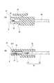
図1及び図2は、本発明に係るオスコネクタ10、メスコネクタ20、メス端子30、及びフラットケーブル40を備えたコネクタ構造を示すものである。 1 and 2 show a connector structure including a
オスコネクタ10は、図3に示すように、インナコネクタとして形成されたメスコネクタ20に対するアウタコネクタとして形成される。このオスコネクタ10は、図4及び図5に示すように、後述するコネクタハウジング11によってフラットケーブル40の先端側(後述する露出導体41Aが位置する側)が支持されており、フラットケーブル40の先端側を除く残りの部分が、コネクタハウジング11の後述する開口部11Aとは反対側の端部から外部に引き出された状態となっている。 As shown in FIG. 3, the
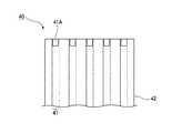
なお、本実施形態のフラットケーブル40は、図6に示すように、複数(本実施形態では5極)の平板型の導体41と、平面上に並設された各導体41の周囲を覆う適宜樹脂からなる絶縁被覆42と、を備えている。また、本発明のフラットケーブル40は、その一端において、絶縁被覆42の先端部分を剥がして内部の導体を露出(以下、「露出導体41A」とよぶ)させてある。 As shown in FIG. 6, the
コネクタハウジング11は、適宜の絶縁性の樹脂材料で形成され、相手側のコネクタであるメスコネクタ20の挿入を受け入れる、略ロ字形に開口した開口部11Aを先端部分に有している。また、コネクタハウジング11の開口部11A内には、前述した各露出導体41A間に位置する絶縁被覆42を、絶縁被覆42を厚さ方向に挟持するリブ12が形成されている。このリブ12は、開口部11Aの上面および下面から絶縁被覆42に向けて延設されたものである。このため、リブ12は、フラットケーブル40を挟んで上側のリブと下側のリブとに分かれる。このリブ12によってフラットケーブル40の先端側を挟持することにより、コネクタハウジング11はフラットケーブル40を支持している。さらに、このリブ12を複数個形成して開口部11Aを露出導体41Aと同数に仕切ることにより、コネクタハウジング11の開口部11Aには、各導体41毎に端子収容空間αが形成される。この結果、この端子収容空間αに臨む状態で露出導体41Aが配置されることになる。また、コネクタハウジング11には、上面中央部に、メスコネクタ20との嵌合状態を保持するために、ロック用突起13が形成されている。 The
一方、メスコネクタ20は、図7に示すように、アウタコネクタとして形成されたオスコネクタ10に対するインナコネクタとして形成され、オスコネクタ10の開口部11Aに挿入されることによって、オスコネクタ10とメスコネクタ20が嵌合する。また、メスコネクタ20は、オスコネクタ10と嵌合させことで、オスコネクタ10に取付けてあるフラットケーブル40の先端の露出導体41Aにメス端子30が接触するようになっている。本実施形態のメスコネクタ20は、図7〜図10に示すように、電線50の先端部とそれぞれ接続された複数個(本実施形態では5個)のメス端子30と、これらのメス端子30を着脱可能な状態で支持するコネクタハウジング21と、を備えている。 On the other hand, as shown in FIG. 7, the
コネクタハウジング21は、図10に示すように、オスコネクタ10に対する嵌合方向前方(図10の左側)の先端部に設けた突起部22と、先端に位置する突起部22から嵌合方向後方(図10の右側)の後端部にかけて形成された空洞が形成され、その空洞にメス端子30を収容するメス端子室23と、上面に設けた嵌合ロック部25と、オスコネクタ10のコネクタハウジング11の先端面が当接することによって接合の際の正確な位置決めがなされるストップ面26と、を有する。コネクタハウジング21は、図7、図9に示すように、突起部22およびメス端子室23を一組とするメス端子保持部27が複数個形成されており、隣り合うメス端子保持部27の間にはスリット24が形成されている。 As shown in FIG. 10, the
各突起部22は、相手方コネクタであるオスコネクタ10とメスコネクタ20が嵌合した際に、各端子収容空間αに収容される形状である(言い換えると、スリット24がオスコネクタのリブ12を収容する形状である。)。また、各突起部22は、上下方向の略中央に、水平方向に切り欠いて形成された空間(フラットケーブル収容空間)βが形成され、そのフラットケーブル収容空間βはメス端子室23の上面および下面に挟まれるように位置する(図7、図10参照)。 Each
メス端子30が収容されるメス端子室23には、嵌合方向後方からメス端子30が挿入され該メス端子室23に固定される。フラットケーブル収容空間β(図8参照)は、メス端子室23の嵌合方向前方に位置する。 A
スリット24は、各メス端子保持部27の間に形成された溝であって、オスコネクタ10のリブ12を収容可能な形状である(リブ収容空間と称することがある。)。 The
嵌合ロック部25は、相手方コネクタであるオスコネクタ10を嵌合させた際にその嵌合状態を保持しておくために、コネクタハウジング11の上面中央部に設けたロック用突起13と嵌合するようになっている。 The
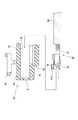
メス端子30は、図11及び図12に示すように、略四角柱状の細長い端子本体31と、メスコネクタ20とオスコネクタ10とを嵌合させたときにフラットケーブル40の露出導体41Aが収容される、端子本体31の先端に設けた切欠き状の導体収容空間γと、メスコネクタ20とオスコネクタ10とを嵌合させたときに導体収容空間γ内に位置する露出導体41Aを厚さ方向に挟着させるとともに露出導体41Aとの間を電気的に導通させるために、端子本体31先端部の導体収容空間γに設けた導電性を有するアーム32と、同じく端子本体31先端部の導体収容空間γにおいてアーム32に対向して突出して設けた、可撓性及び導電性を有する圧接突起33と、を備えている。アーム32と圧接突起33を総称して挟持部と称することがある。導体収容空間γは、フラットケーブル収容空間βと同様、フラットケーブル40の一端側の露出導体41Aが収容される空間であり、フラットケーブル収容空間βの空間内部に導体収容空間γが含まれる。このため、コネクタハウジング21は、フラットケーブル収容空間βにフラットケーブル40の一端が収容された際にフラットケーブル40の一端において露出した露出導体41Aが導体収容空間γに収容されるようメス端子30を支持することになる。 As shown in FIGS. 11 and 12, the
端子本体31は、金属材料で形成されており、コネクタハウジング21の嵌合方向後方からメス端子室23に挿入させ、メス端子室23に固定させる。このため、端子本体31の先端部には、図11に示すように、弾性を付与させてメス端子室23内の天井面に圧接させるために片持ち(カンチレバー)構造の突起部31Aを有する。 The
アーム32は、露出導体41Aと確実の接触導通させるために断面略へ字形に形成されている。本実施形態のアーム32は、上述したように、相手方コネクタであるオスコネクタ10と嵌合させることにより、オスコネクタ10に取付けたフラットケーブル40先端の露出導体41Aを、圧接突起33との間で上下方向から弾性力で挟みつけることで、露出導体41Aとメス端子30側とが接触して導通され電気的に接続される。 The
電線50は、先述したように、一般に広く用いられる構造のものが使用されており、具体的には、図8に示すように、フィラメント状の複数の線材(芯線)を縒り合せて形成した導体51と、この導体51の外周に形成した絶縁被覆52とを有する。 As described above, the
次に、本実施形態の作用について説明する。
本実施形態のオスコネクタ10には、図3に示すように、コネクタハウジング11の開口部11Aにリブ12が形成されている。従って、コネクタハウジング11の開口部11Aには、リブ12で間仕切りされた端子収容空間αが形成されている。また、各端子収容空間αには、端子収容空間αに臨む状態で、露出導体41Aがそれぞれ配置されている。Next, the operation of this embodiment will be described.
As shown in FIG. 3, the
一方、メスコネクタ20のコネクタハウジング21には、オスコネクタ10をメスコネクタ20が嵌合した際に、各端子収容空間αに収容されるようにメス端子保持部27が形成されているとともに、メス端子室23にはメス端子30が装着されている。また、メスコネクタ20のコネクタハウジング21内部の先端部には、図2、10に示すように、フラットケーブル収容空間βが形成されている。また、メス端子30は、フラットケーブル収容空間βの内部に導体収容空間γが含まれるように、メス端子室23に装着されている。 On the other hand, in the
オスコネクタ10をメスコネクタ20と嵌合させると、図1に示すように、メスコネクタ20のコネクタハウジング21の各メス端子保持部27が、露出導体41Aが配設されている端子収容空間αに入り込んでくる。端子収容空間αに一つのメス端子保持部27を収容することにより、フラットケーブル40の一つの導体41毎に、メス端子30を割り当てることができる。このため、フラットケーブル40の一つの導体41に複数のメス端子30が接触することがない。 When the
従って、オスコネクタ10をメスコネクタ20と嵌合させると、露出導体41Aは、コネクタハウジング21側のフラットケーブル収容空間βを通過し、メス端子30側の導体収容空間γに進入していくこととなる。ここで、メス端子30側の導体収容空間γには、アーム32及び圧接突起33を設けており、アーム32及び圧接突起33との間で露出導体41Aが上下方向から弾性力で挟みつけられることで、露出導体41Aとメス端子30側とが接触して導通され、電気的に接続されるわけである。 Therefore, when the
次に、本実施形態のオスコネクタ10にフラットケーブル40を固定する例について説明する。ここでは、オスコネクタ10のコネクタハウジング11の開口部11Aとは反対側の端部に、フラットケーブル40を挿入させるための貫通空間11B(図1、4、5参照)を形成しておく。この貫通空間11Bは、リブ12に達している。そして、コネクタハウジング11の貫通空間11Bに、露出導体41Aを形成したフラットケーブル40の先端側を挿入する。これにより、上側のリブと下側のリブとによって、貫通空間11Bに挿入されたフラットケーブル40を挟持することができる。 Next, the example which fixes the
また、本実施形態のオスコネクタ10にフラットケーブル40を固定する他例について説明する。ここでは、オスコネクタ10のコネクタハウジング11を、上側のリブを含む上ハウジングと下側のリブを含む下ハウジングに分割可能な形状としておく。そして、その上、下ハウジングをフラットケーブル40の上下方向から挟み込むことによって、フラットケーブル40を挟持する。 Moreover, the other example which fixes the
また、本実施形態のオスコネクタ10にフラットケーブル40を固定する別の他例について説明する。ここでは、フラットケーブル40については、予め先端部分から絶縁被覆42を剥離させて露出導体41Aを形成しておく。そして、このフラットケーブル40の先端側を金型のキャビティ内の所定位置にセットさせておき、樹脂を射出させるなどして一体にインサート成形する。このように、オスコネクタ10のコネクタハウジング11にフラットケーブル40を固定する手法は各種考えられるが、本発明において重要な点は、絶縁被覆42が除去され導体41それぞれが露出したフラットケーブル40の一端が開口部11Aに臨むように、コネクタハウジング11にフラットケーブル40を固定することである。 Another example of fixing the
以上、本発明の実施形態のコネクタによれば、オスコネクタ10には端子を設けていないので、フラットケーブル40と他の電気接続部材とを接続させるために必要な部品の点数を削減することができるとともに、製造コストの削減及び軽量化を図ることができる。 As described above, according to the connector of the embodiment of the present invention, since the
また、コネクタハウジング11がフラットケーブル40を上下から挟持するため、フラットケーブル40の一端において露出した露出導体41Aがメス端子30に接触することによって折れ曲がることを防ぐことができる。この結果、フラットケーブル40の一端において露出した露出導体41Aとメス端子30を確実に接触させることができる。なお、フラットケーブル40を挟持する位置は、フラットケーブル40の一端において導体41が露出している箇所以外であれば、何処でも構わないが、その位置がフラットケーブル40の一端側に近づくほど、上述のフラットケーブル40の一端において露出した導体の折れ曲がりを顕著に防ぐことができる。 Further, since the
10 オスコネクタ
11 コネクタハウジング
11A 開口部
11B 貫通空間
12 リブ
13 ロック用突起
20 メスコネクタ
21 コネクタハウジング
22 突起部
23 メス端子室
24 スリット(リブ収容空間)
25 嵌合ロック部
26 ストップ面
27 メス端子保持部
30 メス端子
31A 突起部
31 端子本体
32 アーム
33 圧接突起
40 フラットケーブル
41 導体
41A 露出導体
42 絶縁被覆
50 電線
51 芯線(導体)
52 絶縁被覆
α 端子収容空間
β フラットケーブル収容空間
γ 導体収容空間DESCRIPTION OF
25
52 Insulation coating α Terminal housing space β Flat cable housing space γ Conductor housing space
Claims (3)
Translated fromJapanese前記フラットケーブルを支持するコネクタハウジングと、
を備えるコネクタであって、
前記コネクタハウジングは、相手方コネクタと嵌合した際に該相手方コネクタを収容する開口部を有するとともに、前記絶縁被覆が除去され前記導体それぞれが露出した前記フラットケーブルの一端が前記開口部に臨むように、前記導体が露出した箇所を除く前記一端の任意の箇所を、その厚さ方向に挟持することによって該フラットケーブルを支持し、
前記フラットケーブルの一端において露出した前記導体の少なくとも一つは、相手方コネクタと嵌合した際、該相手方コネクタの端子と接触する、
ことを特徴とするコネクタ。A flat cable in which a plurality of conductors are juxtaposed on a plane, and an insulation coating surrounds each conductor;
A connector housing for supporting the flat cable;
A connector comprising:
The connector housing has an opening for receiving the mating connector when mated with the mating connector, and one end of the flat cable from which the insulating coating is removed and each of the conductors is exposed faces the opening.The flat cable is supportedby sandwiching the arbitrary portion of the one end excluding the exposed portion of the conductor in the thickness direction thereof ,
At least one of the conductors exposed at one end of the flat cable is in contact with a terminal of the mating connector when mated with the mating connector;
A connector characterized by that.
ことを特徴とする請求項1に記載のコネクタ。The connector housing supports the flat cable by sandwiching the insulating coating located between the exposed adjacent conductors at one end of the flat cable in the thickness direction thereof.
The connector according to claim1 .
ことを特徴とする請求項1に記載のコネクタ。Inside the opening of the connector housing, the insulating coating located between the exposed adjacent conductors at one end of the flat cable is sandwiched in the thickness direction. The upper and lower surfaces of the opening are connected to the insulating coating. Ribs extending toward the terminal are formed, and one terminal of the mating connector can be accommodated in a terminal accommodating space sandwiched by the adjacent ribs.
The connector according to claim1 .
Priority Applications (5)
| Application Number | Priority Date | Filing Date | Title |
|---|---|---|---|
| JP2009098717AJP5289154B2 (en) | 2009-04-15 | 2009-04-15 | connector |
| US13/263,245US8550841B2 (en) | 2009-04-15 | 2010-04-14 | Flat cable connector having cable support structure |
| EP10764489.0AEP2421098B1 (en) | 2009-04-15 | 2010-04-14 | Connector |
| CN201080016656.2ACN102396117B (en) | 2009-04-15 | 2010-04-14 | Connector |
| PCT/JP2010/056709WO2010119905A1 (en) | 2009-04-15 | 2010-04-14 | Connector |
Applications Claiming Priority (1)
| Application Number | Priority Date | Filing Date | Title |
|---|---|---|---|
| JP2009098717AJP5289154B2 (en) | 2009-04-15 | 2009-04-15 | connector |
Publications (2)
| Publication Number | Publication Date |
|---|---|
| JP2010251094A JP2010251094A (en) | 2010-11-04 |
| JP5289154B2true JP5289154B2 (en) | 2013-09-11 |
Family
ID=42982564
Family Applications (1)
| Application Number | Title | Priority Date | Filing Date |
|---|---|---|---|
| JP2009098717AExpired - Fee RelatedJP5289154B2 (en) | 2009-04-15 | 2009-04-15 | connector |
Country Status (5)
| Country | Link |
|---|---|
| US (1) | US8550841B2 (en) |
| EP (1) | EP2421098B1 (en) |
| JP (1) | JP5289154B2 (en) |
| CN (1) | CN102396117B (en) |
| WO (1) | WO2010119905A1 (en) |
Families Citing this family (3)
| Publication number | Priority date | Publication date | Assignee | Title |
|---|---|---|---|---|
| US8840415B2 (en)* | 2011-10-05 | 2014-09-23 | Tyco Electronics Corporation | Power cable connector |
| US10238012B2 (en)* | 2013-10-02 | 2019-03-19 | Hitachi Automotive Systems, Ltd | Waterproof component-suppressing electronic control device |
| US9888571B2 (en) | 2014-09-02 | 2018-02-06 | Apple Inc. | Receptacle for connecting to flexible circuit board |
Family Cites Families (58)
| Publication number | Priority date | Publication date | Assignee | Title |
|---|---|---|---|---|
| US3941448A (en)* | 1974-07-29 | 1976-03-02 | E. I. Du Pont De Nemours & Company | Connector block |
| NL163072C (en)* | 1975-12-31 | 1980-07-15 | Du Pont | CONTACT DEVICE FOR A SLIDING PLATE WITH PRINTED WIRING, AND A CONTACT ELEMENT TO BE USED THEREIN. |
| JPH0615273B2 (en)* | 1986-01-20 | 1994-03-02 | 株式会社アイテイテイキャノン | IC card |
| US5169324A (en)* | 1986-11-18 | 1992-12-08 | Lemke Timothy A | Plug terminator having a grounding member |
| US4824383A (en)* | 1986-11-18 | 1989-04-25 | E. I. Du Pont De Nemours And Company | Terminator and corresponding receptacle for multiple electrical conductors |
| US5057028A (en)* | 1986-11-18 | 1991-10-15 | E. I. Du Pont De Nemours And Company | Receptacle having a nosepeice to receive cantilevered spring contacts |
| US4971574A (en)* | 1989-12-08 | 1990-11-20 | W. L. Gore & Associates, Inc. | Shielded connector assembly for flat cable |
| US5111362A (en)* | 1990-09-18 | 1992-05-05 | Intel Corporation | Enclosure assembly with two identical covers having modifiable supports for asymmetrically housing a printed circuit board or the like |
| US5240430A (en)* | 1991-10-31 | 1993-08-31 | Amp Incorporated | Electrical connector for cable to circit board application |
| US5213534A (en)* | 1992-07-31 | 1993-05-25 | Molex Incorporated | Electrical connector assembly for flat flexible cable |
| US5295863A (en)* | 1992-09-17 | 1994-03-22 | Arrowsmith Shelburne, Inc. | Electrical connector for coaxial cable |
| JP2820855B2 (en)* | 1993-04-07 | 1998-11-05 | トーマス アンド ベッツ コーポレーション | connector |
| US5466162A (en)* | 1993-09-30 | 1995-11-14 | The Whitaker Corporation | Removable high density connector |
| JPH08236225A (en)* | 1994-10-28 | 1996-09-13 | Whitaker Corp:The | Electrical connector |
| JP3140683B2 (en)* | 1996-05-27 | 2001-03-05 | 矢崎総業株式会社 | Flat cable connection structure |
| JP3196195B2 (en)* | 1996-06-12 | 2001-08-06 | 船井電機株式会社 | Cable holder and cable fixing method |
| JPH10223269A (en)* | 1997-02-05 | 1998-08-21 | Kel Corp | ID connector |
| US6264500B1 (en)* | 1997-03-06 | 2001-07-24 | I-Pex Co., Ltd. | Electrical connector with cable guide slot |
| US5800186A (en)* | 1997-03-13 | 1998-09-01 | Framatome Connectors Usa, Inc. | Printed circuit board assembly |
| JPH11312568A (en)* | 1998-04-27 | 1999-11-09 | Yazaki Corp | Wire and flat cable connector for electrical connection device for steering |
| JP3859871B2 (en)* | 1998-06-25 | 2006-12-20 | エフシーアイジャパン株式会社 | connector |
| JP2000150030A (en)* | 1998-11-17 | 2000-05-30 | Japan Aviation Electronics Industry Ltd | Cable connector and its connection method |
| JP3265424B2 (en)* | 1999-03-29 | 2002-03-11 | 日本航空電子工業株式会社 | Cable connector and its connection method |
| US6139363A (en)* | 1999-07-09 | 2000-10-31 | Hon Hai Precision Ind. Co., Ltd. | Micro connector assembly and method of making the same |
| JP2001068189A (en)* | 1999-08-27 | 2001-03-16 | Yazaki Corp | Connector structure |
| JP2001068182A (en)* | 1999-08-27 | 2001-03-16 | Sony Computer Entertainment Inc | Board connecting structure, electronic equipment, and connector |
| US6217372B1 (en)* | 1999-10-08 | 2001-04-17 | Tensolite Company | Cable structure with improved grounding termination in the connector |
| JP3703665B2 (en)* | 1999-11-16 | 2005-10-05 | ヒロセ電機株式会社 | Electrical connector connection structure |
| JP2001143797A (en)* | 1999-11-17 | 2001-05-25 | Kel Corp | Cable connector |
| WO2001049090A1 (en)* | 1999-12-27 | 2001-07-05 | Ositech Communications Inc. | Extendable and retractable type 2 pc card and method of operation thereof |
| JP2001325875A (en)* | 2000-05-18 | 2001-11-22 | Yazaki Corp | Pluggable fuse |
| EP1162631B1 (en)* | 2000-06-08 | 2006-07-26 | I & T Innovation Technology Entwicklungs- und Holding Aktiengesellschaft | Connector for contacting a flat ribbon-cable |
| US6428344B1 (en)* | 2000-07-31 | 2002-08-06 | Tensolite Company | Cable structure with improved termination connector |
| JP3687548B2 (en)* | 2001-02-16 | 2005-08-24 | 住友電装株式会社 | Waterproof connector for flexible flat cable |
| US6659794B2 (en)* | 2001-03-23 | 2003-12-09 | Calsonic Kansei Corporation | Connector for connecting FFC |
| DE10115283C1 (en)* | 2001-03-28 | 2002-10-02 | Fci Automotive Deutschland Gmb | Flex connection arrangement with spring housing |
| DE10116454C2 (en)* | 2001-04-03 | 2003-08-14 | Fci Automotive Deutschland Gmb | Connection arrangement for flex ribbon cable |
| JP3607878B2 (en)* | 2001-04-25 | 2005-01-05 | 日本圧着端子製造株式会社 | Flexible board connector |
| EP1311026A3 (en)* | 2001-11-07 | 2005-06-08 | Tyco Electronics AMP GmbH | Connector for detachably connecting an electrically conductive foil to a contact |
| US6854995B2 (en)* | 2001-11-07 | 2005-02-15 | Tyco Electronics Amp Gmbh | Connector for detachably connecting an electrically conductive foil to a contact |
| JP3772304B2 (en)* | 2002-02-18 | 2006-05-10 | オリオン電機株式会社 | Interconnection structure of printed circuit boards |
| US7004787B2 (en)* | 2002-06-11 | 2006-02-28 | Henry Milan | Universal computer cable with quick connectors and interchangeable ends, and system and method utilizing the same |
| US7035126B1 (en)* | 2002-06-10 | 2006-04-25 | Comarco Wireless Technologies, Inc. | Programmable power supply capable of receiving AC and DC power input |
| US6604966B1 (en)* | 2002-12-18 | 2003-08-12 | Fci Americas Technology, Inc. | Flexible cable electrical connector |
| EP1439611B1 (en)* | 2003-01-16 | 2006-06-28 | Tyco Electronics AMP GmbH | Connector for a ribbon cable |
| JP2005004993A (en)* | 2003-06-09 | 2005-01-06 | Jst Mfg Co Ltd | Plug-type connector and electrical connector including the same |
| JP3595940B1 (en)* | 2003-10-23 | 2004-12-02 | 日本航空電子工業株式会社 | ID connector |
| JP4124760B2 (en)* | 2003-12-22 | 2008-07-23 | モレックス インコーポレーテッド | Coaxial cable connector and cable holder |
| JP2005259560A (en) | 2004-03-12 | 2005-09-22 | Fujikura Ltd | Flat harness connector |
| JP4291800B2 (en)* | 2005-06-21 | 2009-07-08 | 日本圧着端子製造株式会社 | Electrical connection device and connector |
| CN2874807Y (en)* | 2005-10-31 | 2007-02-28 | 富士康(昆山)电脑接插件有限公司 | Cable connector module |
| JP2007214087A (en)* | 2006-02-13 | 2007-08-23 | Fujikura Ltd | connector |
| JP4776415B2 (en) | 2006-03-28 | 2011-09-21 | 古河電気工業株式会社 | Flat cable and terminal connection method and electrical connector |
| JP2007287363A (en)* | 2006-04-13 | 2007-11-01 | Fujikura Ltd | Connection structure between flexible flat circuit boards |
| TW200803057A (en)* | 2006-06-27 | 2008-01-01 | P Two Ind Inc | Electrical connector |
| CN201054403Y (en)* | 2007-03-02 | 2008-04-30 | 富士康(昆山)电脑接插件有限公司 | Cable connector |
| JP2009098717A (en) | 2007-10-12 | 2009-05-07 | Denso Wave Inc | Bar code reader |
| US7942695B1 (en)* | 2010-09-23 | 2011-05-17 | Yueh-Chiung Lu | Cable end connector |
- 2009
- 2009-04-15JPJP2009098717Apatent/JP5289154B2/ennot_activeExpired - Fee Related
- 2010
- 2010-04-14CNCN201080016656.2Apatent/CN102396117B/ennot_activeExpired - Fee Related
- 2010-04-14WOPCT/JP2010/056709patent/WO2010119905A1/enactiveApplication Filing
- 2010-04-14USUS13/263,245patent/US8550841B2/enactiveActive
- 2010-04-14EPEP10764489.0Apatent/EP2421098B1/ennot_activeNot-in-force
Also Published As
| Publication number | Publication date |
|---|---|
| CN102396117B (en) | 2014-06-04 |
| US20120034815A1 (en) | 2012-02-09 |
| EP2421098B1 (en) | 2017-01-11 |
| EP2421098A4 (en) | 2013-03-20 |
| WO2010119905A1 (en) | 2010-10-21 |
| JP2010251094A (en) | 2010-11-04 |
| EP2421098A1 (en) | 2012-02-22 |
| US8550841B2 (en) | 2013-10-08 |
| CN102396117A (en) | 2012-03-28 |
Similar Documents
| Publication | Publication Date | Title |
|---|---|---|
| JP5563241B2 (en) | Electrical connector | |
| US20110250783A1 (en) | Cable assembly with improved terminating means and method of making the same | |
| JP4652742B2 (en) | connector | |
| JP7195974B2 (en) | connector | |
| JP2000260497A (en) | Connection method and connector of thin wire coaxial cable | |
| EP1744405A2 (en) | Electric connector and method for manufacturing the same | |
| CN102801008B (en) | cable connector | |
| CN113826283A (en) | Connecting Devices and Connectors | |
| JP5289154B2 (en) | connector | |
| CN110800161B (en) | Connectors and Connector Components | |
| JP2007234490A (en) | Connector for coaxial cable | |
| JP4864340B2 (en) | Coaxial cable electrical connector | |
| JP2020187896A (en) | connector | |
| US9590322B2 (en) | Connector | |
| CN209088147U (en) | Connectors and connector assemblies for connecting wires | |
| US7207829B2 (en) | Electric connector | |
| JP4381959B2 (en) | Wire harness joint connector and manufacturing method thereof | |
| JP5156288B2 (en) | Unit cable for indoor wiring | |
| JP2006172738A (en) | Plug connector, plug contact and assembly method of plug connector | |
| JP2007299578A (en) | Waterproof type joint connector | |
| CN1328825C (en) | Electric Connector and its assembling method | |
| JP2000299167A (en) | Electrical connector | |
| JP7596144B2 (en) | Cable branch connection structure | |
| JP7431091B2 (en) | Connecting terminal | |
| CN112751222B (en) | Positioning orientation of wiring relative to electrical connector |
Legal Events
| Date | Code | Title | Description |
|---|---|---|---|
| A621 | Written request for application examination | Free format text:JAPANESE INTERMEDIATE CODE: A621 Effective date:20120229 | |
| A131 | Notification of reasons for refusal | Free format text:JAPANESE INTERMEDIATE CODE: A131 Effective date:20130212 | |
| A521 | Request for written amendment filed | Free format text:JAPANESE INTERMEDIATE CODE: A523 Effective date:20130409 | |
| TRDD | Decision of grant or rejection written | ||
| A01 | Written decision to grant a patent or to grant a registration (utility model) | Free format text:JAPANESE INTERMEDIATE CODE: A01 Effective date:20130507 | |
| A61 | First payment of annual fees (during grant procedure) | Free format text:JAPANESE INTERMEDIATE CODE: A61 Effective date:20130604 | |
| R150 | Certificate of patent or registration of utility model | Ref document number:5289154 Country of ref document:JP Free format text:JAPANESE INTERMEDIATE CODE: R150 | |
| R250 | Receipt of annual fees | Free format text:JAPANESE INTERMEDIATE CODE: R250 | |
| R250 | Receipt of annual fees | Free format text:JAPANESE INTERMEDIATE CODE: R250 | |
| R250 | Receipt of annual fees | Free format text:JAPANESE INTERMEDIATE CODE: R250 | |
| R250 | Receipt of annual fees | Free format text:JAPANESE INTERMEDIATE CODE: R250 | |
| R250 | Receipt of annual fees | Free format text:JAPANESE INTERMEDIATE CODE: R250 | |
| R250 | Receipt of annual fees | Free format text:JAPANESE INTERMEDIATE CODE: R250 | |
| LAPS | Cancellation because of no payment of annual fees |