JP5285418B2 - Resonant non-contact power supply device - Google Patents
Resonant non-contact power supply deviceDownload PDFInfo
- Publication number
- JP5285418B2 JP5285418B2JP2008328831AJP2008328831AJP5285418B2JP 5285418 B2JP5285418 B2JP 5285418B2JP 2008328831 AJP2008328831 AJP 2008328831AJP 2008328831 AJP2008328831 AJP 2008328831AJP 5285418 B2JP5285418 B2JP 5285418B2
- Authority
- JP
- Japan
- Prior art keywords
- power
- power supply
- coil
- primary
- resonance
- Prior art date
- Legal status (The legal status is an assumption and is not a legal conclusion. Google has not performed a legal analysis and makes no representation as to the accuracy of the status listed.)
- Expired - Fee Related
Links
Images


Classifications
- B—PERFORMING OPERATIONS; TRANSPORTING
- B60—VEHICLES IN GENERAL
- B60L—PROPULSION OF ELECTRICALLY-PROPELLED VEHICLES; SUPPLYING ELECTRIC POWER FOR AUXILIARY EQUIPMENT OF ELECTRICALLY-PROPELLED VEHICLES; ELECTRODYNAMIC BRAKE SYSTEMS FOR VEHICLES IN GENERAL; MAGNETIC SUSPENSION OR LEVITATION FOR VEHICLES; MONITORING OPERATING VARIABLES OF ELECTRICALLY-PROPELLED VEHICLES; ELECTRIC SAFETY DEVICES FOR ELECTRICALLY-PROPELLED VEHICLES
- B60L53/00—Methods of charging batteries, specially adapted for electric vehicles; Charging stations or on-board charging equipment therefor; Exchange of energy storage elements in electric vehicles
- B60L53/10—Methods of charging batteries, specially adapted for electric vehicles; Charging stations or on-board charging equipment therefor; Exchange of energy storage elements in electric vehicles characterised by the energy transfer between the charging station and the vehicle
- B60L53/12—Inductive energy transfer
- B60L53/124—Detection or removal of foreign bodies
- B—PERFORMING OPERATIONS; TRANSPORTING
- B60—VEHICLES IN GENERAL
- B60L—PROPULSION OF ELECTRICALLY-PROPELLED VEHICLES; SUPPLYING ELECTRIC POWER FOR AUXILIARY EQUIPMENT OF ELECTRICALLY-PROPELLED VEHICLES; ELECTRODYNAMIC BRAKE SYSTEMS FOR VEHICLES IN GENERAL; MAGNETIC SUSPENSION OR LEVITATION FOR VEHICLES; MONITORING OPERATING VARIABLES OF ELECTRICALLY-PROPELLED VEHICLES; ELECTRIC SAFETY DEVICES FOR ELECTRICALLY-PROPELLED VEHICLES
- B60L53/00—Methods of charging batteries, specially adapted for electric vehicles; Charging stations or on-board charging equipment therefor; Exchange of energy storage elements in electric vehicles
- B60L53/30—Constructional details of charging stations
- B60L53/35—Means for automatic or assisted adjustment of the relative position of charging devices and vehicles
- B60L53/36—Means for automatic or assisted adjustment of the relative position of charging devices and vehicles by positioning the vehicle
- B—PERFORMING OPERATIONS; TRANSPORTING
- B60—VEHICLES IN GENERAL
- B60L—PROPULSION OF ELECTRICALLY-PROPELLED VEHICLES; SUPPLYING ELECTRIC POWER FOR AUXILIARY EQUIPMENT OF ELECTRICALLY-PROPELLED VEHICLES; ELECTRODYNAMIC BRAKE SYSTEMS FOR VEHICLES IN GENERAL; MAGNETIC SUSPENSION OR LEVITATION FOR VEHICLES; MONITORING OPERATING VARIABLES OF ELECTRICALLY-PROPELLED VEHICLES; ELECTRIC SAFETY DEVICES FOR ELECTRICALLY-PROPELLED VEHICLES
- B60L53/00—Methods of charging batteries, specially adapted for electric vehicles; Charging stations or on-board charging equipment therefor; Exchange of energy storage elements in electric vehicles
- B60L53/30—Constructional details of charging stations
- B60L53/35—Means for automatic or assisted adjustment of the relative position of charging devices and vehicles
- B60L53/38—Means for automatic or assisted adjustment of the relative position of charging devices and vehicles specially adapted for charging by inductive energy transfer
- B60L53/39—Means for automatic or assisted adjustment of the relative position of charging devices and vehicles specially adapted for charging by inductive energy transfer with position-responsive activation of primary coils
- B—PERFORMING OPERATIONS; TRANSPORTING
- B60—VEHICLES IN GENERAL
- B60L—PROPULSION OF ELECTRICALLY-PROPELLED VEHICLES; SUPPLYING ELECTRIC POWER FOR AUXILIARY EQUIPMENT OF ELECTRICALLY-PROPELLED VEHICLES; ELECTRODYNAMIC BRAKE SYSTEMS FOR VEHICLES IN GENERAL; MAGNETIC SUSPENSION OR LEVITATION FOR VEHICLES; MONITORING OPERATING VARIABLES OF ELECTRICALLY-PROPELLED VEHICLES; ELECTRIC SAFETY DEVICES FOR ELECTRICALLY-PROPELLED VEHICLES
- B60L53/00—Methods of charging batteries, specially adapted for electric vehicles; Charging stations or on-board charging equipment therefor; Exchange of energy storage elements in electric vehicles
- B60L53/60—Monitoring or controlling charging stations
- B60L53/62—Monitoring or controlling charging stations in response to charging parameters, e.g. current, voltage or electrical charge
- H—ELECTRICITY
- H02—GENERATION; CONVERSION OR DISTRIBUTION OF ELECTRIC POWER
- H02J—CIRCUIT ARRANGEMENTS OR SYSTEMS FOR SUPPLYING OR DISTRIBUTING ELECTRIC POWER; SYSTEMS FOR STORING ELECTRIC ENERGY
- H02J50/00—Circuit arrangements or systems for wireless supply or distribution of electric power
- H02J50/10—Circuit arrangements or systems for wireless supply or distribution of electric power using inductive coupling
- H02J50/12—Circuit arrangements or systems for wireless supply or distribution of electric power using inductive coupling of the resonant type
- H—ELECTRICITY
- H02—GENERATION; CONVERSION OR DISTRIBUTION OF ELECTRIC POWER
- H02J—CIRCUIT ARRANGEMENTS OR SYSTEMS FOR SUPPLYING OR DISTRIBUTING ELECTRIC POWER; SYSTEMS FOR STORING ELECTRIC ENERGY
- H02J50/00—Circuit arrangements or systems for wireless supply or distribution of electric power
- H02J50/80—Circuit arrangements or systems for wireless supply or distribution of electric power involving the exchange of data, concerning supply or distribution of electric power, between transmitting devices and receiving devices
- H—ELECTRICITY
- H02—GENERATION; CONVERSION OR DISTRIBUTION OF ELECTRIC POWER
- H02J—CIRCUIT ARRANGEMENTS OR SYSTEMS FOR SUPPLYING OR DISTRIBUTING ELECTRIC POWER; SYSTEMS FOR STORING ELECTRIC ENERGY
- H02J7/00—Circuit arrangements for charging or depolarising batteries or for supplying loads from batteries
- H02J7/00032—Circuit arrangements for charging or depolarising batteries or for supplying loads from batteries characterised by data exchange
- H02J7/00034—Charger exchanging data with an electronic device, i.e. telephone, whose internal battery is under charge
- Y—GENERAL TAGGING OF NEW TECHNOLOGICAL DEVELOPMENTS; GENERAL TAGGING OF CROSS-SECTIONAL TECHNOLOGIES SPANNING OVER SEVERAL SECTIONS OF THE IPC; TECHNICAL SUBJECTS COVERED BY FORMER USPC CROSS-REFERENCE ART COLLECTIONS [XRACs] AND DIGESTS
- Y02—TECHNOLOGIES OR APPLICATIONS FOR MITIGATION OR ADAPTATION AGAINST CLIMATE CHANGE
- Y02T—CLIMATE CHANGE MITIGATION TECHNOLOGIES RELATED TO TRANSPORTATION
- Y02T10/00—Road transport of goods or passengers
- Y02T10/60—Other road transportation technologies with climate change mitigation effect
- Y02T10/70—Energy storage systems for electromobility, e.g. batteries
- Y—GENERAL TAGGING OF NEW TECHNOLOGICAL DEVELOPMENTS; GENERAL TAGGING OF CROSS-SECTIONAL TECHNOLOGIES SPANNING OVER SEVERAL SECTIONS OF THE IPC; TECHNICAL SUBJECTS COVERED BY FORMER USPC CROSS-REFERENCE ART COLLECTIONS [XRACs] AND DIGESTS
- Y02—TECHNOLOGIES OR APPLICATIONS FOR MITIGATION OR ADAPTATION AGAINST CLIMATE CHANGE
- Y02T—CLIMATE CHANGE MITIGATION TECHNOLOGIES RELATED TO TRANSPORTATION
- Y02T10/00—Road transport of goods or passengers
- Y02T10/60—Other road transportation technologies with climate change mitigation effect
- Y02T10/7072—Electromobility specific charging systems or methods for batteries, ultracapacitors, supercapacitors or double-layer capacitors
- Y—GENERAL TAGGING OF NEW TECHNOLOGICAL DEVELOPMENTS; GENERAL TAGGING OF CROSS-SECTIONAL TECHNOLOGIES SPANNING OVER SEVERAL SECTIONS OF THE IPC; TECHNICAL SUBJECTS COVERED BY FORMER USPC CROSS-REFERENCE ART COLLECTIONS [XRACs] AND DIGESTS
- Y02—TECHNOLOGIES OR APPLICATIONS FOR MITIGATION OR ADAPTATION AGAINST CLIMATE CHANGE
- Y02T—CLIMATE CHANGE MITIGATION TECHNOLOGIES RELATED TO TRANSPORTATION
- Y02T90/00—Enabling technologies or technologies with a potential or indirect contribution to GHG emissions mitigation
- Y02T90/10—Technologies relating to charging of electric vehicles
- Y02T90/12—Electric charging stations
- Y—GENERAL TAGGING OF NEW TECHNOLOGICAL DEVELOPMENTS; GENERAL TAGGING OF CROSS-SECTIONAL TECHNOLOGIES SPANNING OVER SEVERAL SECTIONS OF THE IPC; TECHNICAL SUBJECTS COVERED BY FORMER USPC CROSS-REFERENCE ART COLLECTIONS [XRACs] AND DIGESTS
- Y02—TECHNOLOGIES OR APPLICATIONS FOR MITIGATION OR ADAPTATION AGAINST CLIMATE CHANGE
- Y02T—CLIMATE CHANGE MITIGATION TECHNOLOGIES RELATED TO TRANSPORTATION
- Y02T90/00—Enabling technologies or technologies with a potential or indirect contribution to GHG emissions mitigation
- Y02T90/10—Technologies relating to charging of electric vehicles
- Y02T90/14—Plug-in electric vehicles
- Y—GENERAL TAGGING OF NEW TECHNOLOGICAL DEVELOPMENTS; GENERAL TAGGING OF CROSS-SECTIONAL TECHNOLOGIES SPANNING OVER SEVERAL SECTIONS OF THE IPC; TECHNICAL SUBJECTS COVERED BY FORMER USPC CROSS-REFERENCE ART COLLECTIONS [XRACs] AND DIGESTS
- Y02—TECHNOLOGIES OR APPLICATIONS FOR MITIGATION OR ADAPTATION AGAINST CLIMATE CHANGE
- Y02T—CLIMATE CHANGE MITIGATION TECHNOLOGIES RELATED TO TRANSPORTATION
- Y02T90/00—Enabling technologies or technologies with a potential or indirect contribution to GHG emissions mitigation
- Y02T90/10—Technologies relating to charging of electric vehicles
- Y02T90/16—Information or communication technologies improving the operation of electric vehicles
Landscapes
- Engineering & Computer Science (AREA)
- Power Engineering (AREA)
- Transportation (AREA)
- Mechanical Engineering (AREA)
- Computer Networks & Wireless Communication (AREA)
- Charge And Discharge Circuits For Batteries Or The Like (AREA)
- Secondary Cells (AREA)
- Current-Collector Devices For Electrically Propelled Vehicles (AREA)
- Dc-Dc Converters (AREA)
- Electric Propulsion And Braking For Vehicles (AREA)
Description
Translated fromJapanese本発明は、共鳴型非接触電力供給装置に関するものである。The present invention relates to a resonance type non-contactpower supply apparatus.
無線で電力を送る技術として共鳴方式(特許文献1等)が挙げられる。この共鳴方式による電力伝送システムは、共鳴用一次コイルから非接触で共鳴用二次コイルに共鳴により電力を伝送するものである。詳しくは、送電側の共鳴用一次コイルに交流電界を印加すると、その周辺に振動磁場が発生し共鳴現象によって受電側の共鳴用二次コイルに電力が伝わる現象を利用している。
ところが、一次コイルと二次コイルとの間に障害物が入った場合等には、一次側の高周波電源においては反射電力によりダメージを受ける虞があり、その対策を講じる必要がある。 However, when an obstacle enters between the primary coil and the secondary coil, the high frequency power supply on the primary side may be damaged by the reflected power, and it is necessary to take countermeasures.
本発明は、このような背景の下になされたものであり、その目的は、電源が反射電力によりダメージを受けることを防止することができる共鳴型非接触電力供給装置を提供することにある。The present invention has been made under such a background, and its objectis to supply to provide a resonance type non-contactpower supply device can be prevented from being damaged by the reflected power .
請求項1に記載の発明では、電源から電力の供給を受ける1次側共振器と、前記1次側共振器と離間して非接触で配置され、磁場を通じて前記1次側共振器から電力を受け取る2次側共振器と、前記2次側共振器から電力の供給を受ける充電器と、前記1次側共振器から前記電源への反射電力を検出する検出部と、前記検出部によって検出された前記反射電力に関する値が予め設定された閾値以上に達するときに前記電源を停止させる制御部と、前記充電器に接続されたバッテリと、を備え、前記閾値は、前記バッテリの充電量の変化に起因して変化したときの前記反射電力に関する値よりも大きな値に設定されていることを要旨とする。In the first aspect of the present invention, the primary side resonator that receives power from a power source and the primary side resonator are arranged in a non-contact manner, and the power is supplied from the primary side resonator through a magnetic field. A secondary resonator that receives the power supply, a charger that receives power from the secondary resonator, a detector that detects reflected power from the primary resonator to the power source, and a detector that detects the reflected power A control unit that stops the power supply when a value related to the reflected power reaches a preset threshold value or more,and a battery connected to the charger, wherein the threshold value is a change in a charge amount of the battery. The gist ofthe present inventionis thatit is set to a value larger than the value related to the reflected power when changed due to the above .
請求項1に記載の発明によれば、検出部により、1次側共振器から電源への反射電力が検出される。そして、検出部によって検出された反射電力に関する値が、バッテリの充電量の変化に起因して変化したときの反射電力に関する値よりも大きな値に設定された閾値以上に達するときに、制御部により電源が停止される。よって、電源が反射電力によりダメージを受けることを防止することができる。According to the first aspect of the present invention, the detection unit detects the reflected power from the primary resonator to the power source. When the value related to the reflected power detected by the detection unit reaches a thresholdvalue set to a valuelarger than the value related to the reflected power when the charge amount changes due to a change in the charge amount of the battery , the control unit The power is turned off. Therefore, it is possible to prevent the power source from being damaged by the reflected power.
請求項2に記載のように、請求項1に記載の共鳴型非接触電力供給装置において前記反射電力に関する値は、前記電源から前記1次側共振器への出力電力に対する、前記1次側共振器から前記電源への反射電力の比であるとよい。
請求項3に記載のように、請求項2に記載の共鳴型非接触電力供給装置において、前記電源および前記1次側共振器は地上側に設置され、前記2次側共振器および前記充電器は車両に搭載されているとよい。
請求項4に記載のように、請求項3に記載の共鳴型非接触電力供給装置において前記車両はハイブリッド車であるとよい。
請求項5に記載のように、請求項1に記載の共鳴型非接触電力供給装置において前記1次側共振器および前記2次側共振器にそれぞれ接続されたコンデンサを更に備えるとよい。The resonance-type contactless power supply device according to claim 1, wherein the value related to the reflected power is the primary-side resonance with respect to the output power from the power source to the primary-side resonator. The ratio of the reflected power from the vessel to the power supply is good.
The resonance-type non-contact power supply device according to
As described in claim 4, in the resonance-type non-contact power supply device according to claim 3, the vehicle may be a hybrid vehicle.
According to a fifth aspect of the present invention, the resonant non-contact power supply device according to the first aspect may further include capacitors respectively connected to the primary side resonator and the secondary side resonator.
本発明によれば、電源が反射電力によりダメージを受けることを防止することができる。According to the presentinvention, it is possibleto power can be prevented from being damaged by the reflected power.
以下、本発明を具体化した一実施形態を図面に従って説明する。
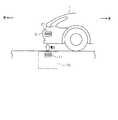
本実施形態では、ハイブリッド車における車載バッテリの充電システム、即ち、車載バッテリを充電するための共鳴型非接触充電装置に適用している。図1に示すように、自動車1において、車体の前面部の例えばフロントバンパーの内部には受電側コイル21が取付けられている。受電側コイル21は銅線を螺旋状に巻回して構成されている。受電側コイル21は軸線(螺旋の中心軸)が車両の上下方向となるように配置されている。DESCRIPTION OF EXEMPLARY EMBODIMENTS Hereinafter, an embodiment of the invention will be described with reference to the drawings.
In the present embodiment, the present invention is applied to an in-vehicle battery charging system in a hybrid vehicle, that is, a resonance type non-contact charging device for charging an in-vehicle battery. As shown in FIG. 1, in the automobile 1, a power
充電スタンドにおける床には地上側設備10が埋設されている。地上側設備10は送電側コイル11を有している。送電側コイル11は銅線を螺旋状に巻回して構成されている。送電側コイル11は軸線(螺旋の中心軸)が地上面に対して直交するように配置されている。そして、自動車1が充電スタンドにおいて充電する際には、送電側コイル11の軸線(螺旋の中心軸)と受電側コイル21の軸線(螺旋の中心軸)とが一致または接近するように配置される。 The
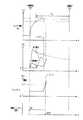
図2には共鳴型非接触充電装置の全体構成を示す。地上側に配置される地上側設備10として、送電側コイル11とコイル12と高周波電源(交流電源)13と電源側コントローラ14を備えている。車両に搭載される車載側機器20として、受電側コイル21とコイル22と整流器23と充電器24と二次電池であるバッテリ25と充電ECU26と車両側コントローラ27とを備えている。 FIG. 2 shows the overall configuration of the resonance type non-contact charging apparatus. As the
高周波電源13は例えば数MHz程度の高周波電力を出力する。高周波電源13にはコイル12が接続され、このコイル12に送電側コイル11が電磁誘導にて結合されており、高周波電源13からコイル12を介して電磁誘導により送電側コイル11に電力が伝送される。このように、共鳴用一次コイルとしての送電側コイル11は高周波電源13からコイル12を介して高周波電力の供給を受ける(高周波電源13の高周波がコイル12を介して送電側コイル11に供給される)。送電側コイル11にはコンデンサCが接続されている。 The high
高周波電源13には電源側コントローラ14が接続されている。電源側コントローラ14から高周波電源13に電源オン/オフ信号が送られ、この信号により高周波電源13がオン/オフされる。高周波電源13において送電側コイル11への出力電力が計測され、この計測された出力電力値が電源側コントローラ14に送られる。また、高周波電源13において送電側コイル11からの反射電力が計測され、この計測された反射電力値が電源側コントローラ14に送られる。電源側コントローラ14は充電開始/停止信号を入力する。この充電開始/停止信号は地上側において人による充電開始/停止のスイッチ操作に伴う信号である。 A power
共鳴用二次コイルとしての受電側コイル21は送電側コイル11と離間して非接触で配置され、送電側コイル11からの電力を磁場共鳴して受電する。受電側コイル21にはコイル22が電磁誘導にて結合され、このコイル22に整流器23が接続されており、受電側コイル21から電磁誘導によりコイル22に電力が伝送され、コイル22から整流器23に送られる。受電側コイル21において給電した電力が整流器23により整流される。受電側コイル21にはコンデンサCが接続されている。 The power
整流器23には充電器24が接続されている。充電器24は受電側コイル21から高周波電力の供給を受けて整流後の電力が充電器24において昇圧等される。充電器24はスイッチング素子を備えており、スイッチング素子をオン/オフ制御することにより出力電圧、出力電流が調整される。充電器24にはバッテリ25が接続され、バッテリ25が充電器24により充電される。 A
充電器24には充電ECU26が接続されている。バッテリ25の充電時には充電ECU26により充電器24での出力電圧、出力電流をモニタしつつ充電器24のスイッチング素子が制御される。また、充電ECU26から充電器24に充電オン/オフ信号が送られ、この信号により充電器24がオン/オフされる。また、充電ECU26はバッテリ電圧Vbを検知している。充電ECU26には車両側コントローラ27が接続されている。充電ECU26から車両側コントローラ27に充電完了信号が送られる。車両側コントローラ27にはイグニッション信号および充電開始/停止信号が送られる。イグニッション信号は、車両のイグニッションスイッチの操作信号である。また、充電開始/停止信号は乗員による充電開始/停止のスイッチ操作に伴う信号である。 A charging ECU 26 is connected to the
地上側設備10の電源側コントローラ14と、車載側機器20の車両側コントローラ27とは無線にて通信できるようになっている。
次に、このように構成した共鳴型非接触充電装置の作用を、図3のタイムチャート等を用いて説明する。The power
Next, the operation of the resonance type non-contact charging apparatus configured as described above will be described with reference to the time chart of FIG.
図3において、上から、バッテリ電圧Vb、出力電力P1および反射電力P2、出力電力P1に対する反射電力P2の比P2/P1、電源オン/オフ信号を示す。
地上側の人または乗員が充電開始スイッチをオン操作する(図3のt1のタイミング)。すると、充電開始信号が電源側コントローラ14または車両側コントローラ27に送られる。電源側コントローラ14と車両側コントローラ27とは無線通信にて充電開始スイッチのオン操作情報を共有している。そして、電源側コントローラ14から高周波電源13への電源オン/オフ信号がHレベルにされる(電源オン指令が出力にされる)。また、車両側コントローラ27は充電ECU26に充電開始指令を出し、これにより、充電ECU26から充電器24への充電オン/オフ信号がHレベルにされる(充電オン指令が出力される)。In FIG. 3, the battery voltage Vb, the output power P1 and the reflected power P2, the ratio P2 / P1 of the reflected power P2 with respect to the output power P1, and the power on / off signal are shown from the top.
A person or passenger on the ground side turns on the charging start switch (timing t1 in FIG. 3). Then, a charging start signal is sent to the power
充電の開始によりバッテリ電圧Vbが上昇していき、予め設定した閾値に達すると(図3のt2のタイミング)、充電ECU26は経時動作を開始する。そして、充電ECU26は閾値を超えてから所定の充電時間Tcが経過すると(図3のt3のタイミング)、充電が完了したとして車両側コントローラ27に充電完了信号を出力する。 When the charging starts, the battery voltage Vb increases and reaches a preset threshold value (timing t2 in FIG. 3), the charging ECU 26 starts to operate with time. Then, when a predetermined charging time Tc elapses after exceeding the threshold value (timing t3 in FIG. 3), the charging ECU 26 outputs a charging completion signal to the vehicle-
車両側コントローラ27は充電完了信号を入力すると、無線通信により電源側コントローラ14に充電が完了したことを通知する。すると、電源側コントローラ14は直ちに高周波電源13への電源オン/オフ信号をLレベルにする(電源オフ指令が出力される)。これにより高周波電源13がオフする。 When the vehicle-
一方、充電ECU26は所定の充電時間Tcが経過すると(図3のt3のタイミング)、充電器24への充電オン/オフ信号をLレベルにする(充電オフ指令が出力される)。これにより充電器24がオフする。 On the other hand, when a predetermined charging time Tc elapses (timing t3 in FIG. 3), the charging ECU 26 sets the charging on / off signal to the
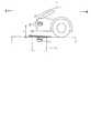
図3は正常時におけるタイムチャートであるが、図4,5は図6に示すようにコイル11,21間に障害物(例えば鉄板)100が入ったときの異常時におけるタイムチャートである。図4は電力伝送中において異常が発生した場合であり、図5は電力伝送開始時に異常が発生した場合である。 3 is a time chart in a normal state, while FIGS. 4 and 5 are time charts in an abnormal state when an obstacle (for example, an iron plate) 100 enters between the
図4において、出力電力P1に対する反射電力P2の比P2/P1は、t10のタイミング以降で急激に大きくなっている。図2の電源側コントローラ14は、出力電力P1に対する反射電力P2の比P2/P1をモニタしている。そして、電源側コントローラ14は、比P2/P1が予め定めた閾値以上になると(t11のタイミング)、電力伝送ができないと判断して電源オン/オフ信号をLレベルにする(電源オフ指令が出力される)。これにより高周波電源13がオフする。閾値は例えば80%程度に設定すればよい。 In FIG. 4, the ratio P2 / P1 of the reflected power P2 to the output power P1 increases rapidly after the timing t10. The power
電力伝送中の異常は、図6に示したように送電側コイル11と受電側コイル21の間に障害物100が入り込んできた場合の他にも、送電側コイル11と受電側コイル21の間の位置関係が変化した場合などが挙げられる。 In addition to the case where the
図5において、出力電力P1に対する反射電力P2の比P2/P1は、t1の電力伝送開始以降急激に大きくなっている。図2の電源側コントローラ14は、出力電力P1に対する反射電力P2の比P2/P1をモニタしている。そして、電源側コントローラ14は、比P2/P1が予め定めた閾値以上になると(t20のタイミング)、正常に電力伝送ができてないと判断して電源オン/オフ信号をLレベルにする(電源オフ指令が出力される)。これにより高周波電源13がオフする。 In FIG. 5, the ratio P2 / P1 of the reflected power P2 with respect to the output power P1 increases rapidly after the start of power transmission at t1. The power
なお、電力伝送開始時の異常は、図6に示したように送電側コイル11と受電側コイル21の間に障害物100がある場合の他にも、受電側コイル21が無い場合や送電側コイル11と受電側コイル21との距離Lが一定値より遠い場合や送電側コイル11と受電側コイル21の共鳴周波数が違う場合などが挙げられる。 Note that the abnormality at the start of power transmission is not limited to the case where there is an
ここで、本実施形態の閾値の設定方法について言及する。
送電側コイルと受電側コイルの間に障害物がある場合等以外にも負荷が変動した場合、共鳴系の入力インピーダンスが変化し、出力電力P1に対する反射電力P2の比P2/P1が大きくなる。しかしながら、負荷が変動した場合には電力伝送を中止したくない。Here, the threshold setting method of this embodiment will be described.
When the load fluctuates other than when there is an obstacle between the power transmission side coil and the power reception side coil, the input impedance of the resonance system changes, and the ratio P2 / P1 of the reflected power P2 to the output power P1 increases. However, when the load fluctuates, it is not desired to stop power transmission.
そこで、本実施形態では、バッテリの充電状態等により負荷が変動した場合の出力電力P1に対する反射電力P2の比P2/P1よりも送電側コイルと受電側コイルの間に障害物がある場合等の出力電力P1に対する反射電力P2の比P2/P1が大きいことに着目し、負荷が変動したときの出力電力P1に対する反射電力P2の比P2/P1よりも閾値を高く設定している。 Therefore, in the present embodiment, when there is an obstacle between the power transmission side coil and the power reception side coil rather than the ratio P2 / P1 of the reflected power P2 to the output power P1 when the load fluctuates due to the state of charge of the battery, etc. Focusing on the fact that the ratio P2 / P1 of the reflected power P2 to the output power P1 is large, the threshold is set higher than the ratio P2 / P1 of the reflected power P2 to the output power P1 when the load fluctuates.
これにより送電側コイルと受電側コイルの間に障害物がある場合等と負荷が変動した場合とを区別することが可能となる。
なお、負荷が変動した場合の出力電力P1に対する反射電力P2の比P2/P1は、10%程度であり、負荷が変動した場合以外(送電側コイルと受電側コイルの間に障害物がある場合等)の場合の出力電力P1に対する反射電力P2の比P2/P1より十分に低いものである。This makes it possible to distinguish between a case where there is an obstacle between the power transmission side coil and the power reception side coil and a case where the load fluctuates.
Note that the ratio P2 / P1 of the reflected power P2 to the output power P1 when the load fluctuates is about 10%, and other than when the load fluctuates (when there is an obstacle between the power transmission side coil and the power reception side coil) Etc.) is sufficiently lower than the ratio P2 / P1 of the reflected power P2 to the output power P1.
以上のように本実施形態によれば、以下のような効果を得ることができる。
(1)共鳴型非接触充電装置の構成として、高周波電源13と、共鳴用一次コイルとしての送電側コイル11と、共鳴用二次コイルとしての受電側コイル21と、充電器24とに加えて、電力比検出手段および停止制御手段としての電源側コントローラ14を設け、電源側コントローラ14により高周波電源13の送電側コイル11への出力電力に対する高周波電源13の送電側コイル11からの反射電力の比を検出して、出力電力に対する反射電力の比が閾値以上になると一次側の高周波電源13を停止させる。これにより、高周波電源13が反射電力によりダメージを受けることを防止することができる。As described above, according to the present embodiment, the following effects can be obtained.
(1) In addition to the high-
(2)高周波電源13および共鳴用一次コイル(11)は地上側に設置され、共鳴用二次コイル(21)および充電器24は車両に搭載されているので、実用上好ましい。
実施形態は前記に限定されるものではなく、例えば、次のように具体化してもよい。(2) Since the high
The embodiment is not limited to the above, and may be embodied as follows, for example.
・ハイブリッド車における共鳴型非接触充電装置に適用したが、車両用に限ることはない。
・送電側コイル11および受電側コイル21は、それぞれ電線が螺旋状に巻回された形状に限らず、一平面状で渦巻き状に巻回された形状としてもよい。この場合、コイルの軸方向の長さが小さくなり、地上に形成する穴の深さを浅くすることができる。-Although applied to a resonance type non-contact charging device in a hybrid vehicle, it is not limited to a vehicle.
The power
・送電側コイル11、コイル12、受電側コイル21、コイル22の外形は、円形に限らず、例えば、四角形や六角形や三角形等の多角形にしたり、あるいは楕円形にしたりしてもよい。 The outer shape of the power
・送電側コイル11および受電側コイル21に接続されたコンデンサCを省略してもよい。しかし、コンデンサCを接続した構成の方が、コンデンサCを省略した場合に比べて、共鳴周波数を下げることができる。また、共鳴周波数が同じであれば、コンデンサCを省略した場合に比べて、送電側コイル11および受電側コイル21の小型化が可能となる。 The capacitor C connected to the power
11…送電側コイル、13…高周波電源、14…電源側コントローラ、21…受電側コイル、23…整流器、24…充電器、25…バッテリ、26…充電ECU、27…車両側コントローラ。 DESCRIPTION OF
Claims (5)
Translated fromJapanese前記1次側共振器と離間して非接触で配置され、磁場を通じて前記1次側共振器から電力を受け取る2次側共振器と、
前記2次側共振器から電力の供給を受ける充電器と、
前記1次側共振器から前記電源への反射電力を検出する検出部と、
前記検出部によって検出された前記反射電力に関する値が予め設定された閾値以上に達するときに前記電源を停止させる制御部と、
前記充電器に接続されたバッテリと、
を備え、
前記閾値は、前記バッテリの充電量の変化に起因して変化したときの前記反射電力に関する値よりも大きな値に設定されていることを特徴とする共鳴型非接触電力供給装置。A primary resonator that receives power from a power source;
A secondary resonator disposed in a non-contact manner apart from the primary resonator and receiving power from the primary resonator through a magnetic field;
A charger that receives power from the secondary-side resonator;
A detector that detects reflected power from the primary-side resonator to the power source;
A controller that stops the power supply when a value related to the reflected power detected by the detector reaches a preset threshold value or more;
A battery connected to the charger;
Equipped witha,
The resonance-type non-contact power supply apparatusaccording to claim 1, wherein the threshold value is set to a value larger than a value related to the reflected power when changed due to a change in a charge amount of the battery .
Priority Applications (2)
| Application Number | Priority Date | Filing Date | Title |
|---|---|---|---|
| JP2008328831AJP5285418B2 (en) | 2008-12-24 | 2008-12-24 | Resonant non-contact power supply device |
| US12/646,305US8766591B2 (en) | 2008-12-24 | 2009-12-23 | Resonance type non-contact charging apparatus |
Applications Claiming Priority (1)
| Application Number | Priority Date | Filing Date | Title |
|---|---|---|---|
| JP2008328831AJP5285418B2 (en) | 2008-12-24 | 2008-12-24 | Resonant non-contact power supply device |
Publications (3)
| Publication Number | Publication Date |
|---|---|
| JP2010154625A JP2010154625A (en) | 2010-07-08 |
| JP2010154625A5 JP2010154625A5 (en) | 2012-09-20 |
| JP5285418B2true JP5285418B2 (en) | 2013-09-11 |
Family
ID=42265029
Family Applications (1)
| Application Number | Title | Priority Date | Filing Date |
|---|---|---|---|
| JP2008328831AExpired - Fee RelatedJP5285418B2 (en) | 2008-12-24 | 2008-12-24 | Resonant non-contact power supply device |
Country Status (2)
| Country | Link |
|---|---|
| US (1) | US8766591B2 (en) |
| JP (1) | JP5285418B2 (en) |
Families Citing this family (132)
| Publication number | Priority date | Publication date | Assignee | Title |
|---|---|---|---|---|
| US7825543B2 (en) | 2005-07-12 | 2010-11-02 | Massachusetts Institute Of Technology | Wireless energy transfer |
| US9421388B2 (en) | 2007-06-01 | 2016-08-23 | Witricity Corporation | Power generation for implantable devices |
| US8115448B2 (en) | 2007-06-01 | 2012-02-14 | Michael Sasha John | Systems and methods for wireless power |
| CN102099958B (en) | 2008-05-14 | 2013-12-25 | 麻省理工学院 | Wireless power transfer including interference enhancement |
| US9065423B2 (en) | 2008-09-27 | 2015-06-23 | Witricity Corporation | Wireless energy distribution system |
| EP3179640A1 (en) | 2008-09-27 | 2017-06-14 | WiTricity Corporation | Wireless energy transfer systems |
| US8587153B2 (en) | 2008-09-27 | 2013-11-19 | Witricity Corporation | Wireless energy transfer using high Q resonators for lighting applications |
| US8461720B2 (en) | 2008-09-27 | 2013-06-11 | Witricity Corporation | Wireless energy transfer using conducting surfaces to shape fields and reduce loss |
| US8907531B2 (en) | 2008-09-27 | 2014-12-09 | Witricity Corporation | Wireless energy transfer with variable size resonators for medical applications |
| US9544683B2 (en) | 2008-09-27 | 2017-01-10 | Witricity Corporation | Wirelessly powered audio devices |
| US9093853B2 (en) | 2008-09-27 | 2015-07-28 | Witricity Corporation | Flexible resonator attachment |
| US8686598B2 (en) | 2008-09-27 | 2014-04-01 | Witricity Corporation | Wireless energy transfer for supplying power and heat to a device |
| US9184595B2 (en) | 2008-09-27 | 2015-11-10 | Witricity Corporation | Wireless energy transfer in lossy environments |
| US8569914B2 (en) | 2008-09-27 | 2013-10-29 | Witricity Corporation | Wireless energy transfer using object positioning for improved k |
| US8957549B2 (en) | 2008-09-27 | 2015-02-17 | Witricity Corporation | Tunable wireless energy transfer for in-vehicle applications |
| US9744858B2 (en) | 2008-09-27 | 2017-08-29 | Witricity Corporation | System for wireless energy distribution in a vehicle |
| US8497601B2 (en) | 2008-09-27 | 2013-07-30 | Witricity Corporation | Wireless energy transfer converters |
| US8552592B2 (en) | 2008-09-27 | 2013-10-08 | Witricity Corporation | Wireless energy transfer with feedback control for lighting applications |
| US8410636B2 (en) | 2008-09-27 | 2013-04-02 | Witricity Corporation | Low AC resistance conductor designs |
| US9105959B2 (en) | 2008-09-27 | 2015-08-11 | Witricity Corporation | Resonator enclosure |
| US8643326B2 (en) | 2008-09-27 | 2014-02-04 | Witricity Corporation | Tunable wireless energy transfer systems |
| US8324759B2 (en) | 2008-09-27 | 2012-12-04 | Witricity Corporation | Wireless energy transfer using magnetic materials to shape field and reduce loss |
| US8400017B2 (en) | 2008-09-27 | 2013-03-19 | Witricity Corporation | Wireless energy transfer for computer peripheral applications |
| US9601261B2 (en) | 2008-09-27 | 2017-03-21 | Witricity Corporation | Wireless energy transfer using repeater resonators |
| US8487480B1 (en) | 2008-09-27 | 2013-07-16 | Witricity Corporation | Wireless energy transfer resonator kit |
| US8901779B2 (en) | 2008-09-27 | 2014-12-02 | Witricity Corporation | Wireless energy transfer with resonator arrays for medical applications |
| US8772973B2 (en) | 2008-09-27 | 2014-07-08 | Witricity Corporation | Integrated resonator-shield structures |
| US8947186B2 (en) | 2008-09-27 | 2015-02-03 | Witricity Corporation | Wireless energy transfer resonator thermal management |
| US8476788B2 (en) | 2008-09-27 | 2013-07-02 | Witricity Corporation | Wireless energy transfer with high-Q resonators using field shaping to improve K |
| US9601270B2 (en) | 2008-09-27 | 2017-03-21 | Witricity Corporation | Low AC resistance conductor designs |
| US9396867B2 (en) | 2008-09-27 | 2016-07-19 | Witricity Corporation | Integrated resonator-shield structures |
| US8963488B2 (en) | 2008-09-27 | 2015-02-24 | Witricity Corporation | Position insensitive wireless charging |
| US8937408B2 (en) | 2008-09-27 | 2015-01-20 | Witricity Corporation | Wireless energy transfer for medical applications |
| US8304935B2 (en) | 2008-09-27 | 2012-11-06 | Witricity Corporation | Wireless energy transfer using field shaping to reduce loss |
| US8629578B2 (en) | 2008-09-27 | 2014-01-14 | Witricity Corporation | Wireless energy transfer systems |
| US8461722B2 (en) | 2008-09-27 | 2013-06-11 | Witricity Corporation | Wireless energy transfer using conducting surfaces to shape field and improve K |
| US9515494B2 (en) | 2008-09-27 | 2016-12-06 | Witricity Corporation | Wireless power system including impedance matching network |
| US8723366B2 (en) | 2008-09-27 | 2014-05-13 | Witricity Corporation | Wireless energy transfer resonator enclosures |
| US8692412B2 (en) | 2008-09-27 | 2014-04-08 | Witricity Corporation | Temperature compensation in a wireless transfer system |
| US9601266B2 (en) | 2008-09-27 | 2017-03-21 | Witricity Corporation | Multiple connected resonators with a single electronic circuit |
| US8922066B2 (en) | 2008-09-27 | 2014-12-30 | Witricity Corporation | Wireless energy transfer with multi resonator arrays for vehicle applications |
| US8901778B2 (en) | 2008-09-27 | 2014-12-02 | Witricity Corporation | Wireless energy transfer with variable size resonators for implanted medical devices |
| US9106203B2 (en) | 2008-09-27 | 2015-08-11 | Witricity Corporation | Secure wireless energy transfer in medical applications |
| US8928276B2 (en) | 2008-09-27 | 2015-01-06 | Witricity Corporation | Integrated repeaters for cell phone applications |
| US8466583B2 (en) | 2008-09-27 | 2013-06-18 | Witricity Corporation | Tunable wireless energy transfer for outdoor lighting applications |
| US9318922B2 (en) | 2008-09-27 | 2016-04-19 | Witricity Corporation | Mechanically removable wireless power vehicle seat assembly |
| US8692410B2 (en) | 2008-09-27 | 2014-04-08 | Witricity Corporation | Wireless energy transfer with frequency hopping |
| US8598743B2 (en) | 2008-09-27 | 2013-12-03 | Witricity Corporation | Resonator arrays for wireless energy transfer |
| US8471410B2 (en) | 2008-09-27 | 2013-06-25 | Witricity Corporation | Wireless energy transfer over distance using field shaping to improve the coupling factor |
| US9160203B2 (en) | 2008-09-27 | 2015-10-13 | Witricity Corporation | Wireless powered television |
| US9246336B2 (en) | 2008-09-27 | 2016-01-26 | Witricity Corporation | Resonator optimizations for wireless energy transfer |
| US8461721B2 (en) | 2008-09-27 | 2013-06-11 | Witricity Corporation | Wireless energy transfer using object positioning for low loss |
| US8946938B2 (en) | 2008-09-27 | 2015-02-03 | Witricity Corporation | Safety systems for wireless energy transfer in vehicle applications |
| US8482158B2 (en) | 2008-09-27 | 2013-07-09 | Witricity Corporation | Wireless energy transfer using variable size resonators and system monitoring |
| US8912687B2 (en) | 2008-09-27 | 2014-12-16 | Witricity Corporation | Secure wireless energy transfer for vehicle applications |
| US8441154B2 (en) | 2008-09-27 | 2013-05-14 | Witricity Corporation | Multi-resonator wireless energy transfer for exterior lighting |
| US8587155B2 (en) | 2008-09-27 | 2013-11-19 | Witricity Corporation | Wireless energy transfer using repeater resonators |
| US8933594B2 (en) | 2008-09-27 | 2015-01-13 | Witricity Corporation | Wireless energy transfer for vehicles |
| US9577436B2 (en) | 2008-09-27 | 2017-02-21 | Witricity Corporation | Wireless energy transfer for implantable devices |
| US8669676B2 (en) | 2008-09-27 | 2014-03-11 | Witricity Corporation | Wireless energy transfer across variable distances using field shaping with magnetic materials to improve the coupling factor |
| US9035499B2 (en) | 2008-09-27 | 2015-05-19 | Witricity Corporation | Wireless energy transfer for photovoltaic panels |
| US8362651B2 (en) | 2008-10-01 | 2013-01-29 | Massachusetts Institute Of Technology | Efficient near-field wireless energy transfer using adiabatic system variations |
| DE102009033236A1 (en) | 2009-07-14 | 2011-01-20 | Conductix-Wampfler Ag | Device for inductive transmission of electrical energy |
| JP5459058B2 (en)* | 2009-11-09 | 2014-04-02 | 株式会社豊田自動織機 | Resonant contactless power transmission device |
| WO2011084936A2 (en)* | 2010-01-05 | 2011-07-14 | Access Business Group International Llc | Inductive charging system for electric vehicle |
| US8841881B2 (en) | 2010-06-02 | 2014-09-23 | Bryan Marc Failing | Energy transfer with vehicles |
| JP5552657B2 (en)* | 2010-07-27 | 2014-07-16 | 株式会社豊田自動織機 | Anomaly detection device |
| CN103053089B (en)* | 2010-07-06 | 2015-09-30 | Lg电子株式会社 | The charging system of automatic sweeping machine |
| US8810206B2 (en)* | 2010-07-22 | 2014-08-19 | Toyota Jidosha Kabushiki Kaisha | Electric motored vehicle and method for controlling electrically charging the same |
| US20130119781A1 (en)* | 2010-07-29 | 2013-05-16 | Toyota Jidosha Kabushiki Kaisha | Resonance type non-contact power supply system |
| KR101184503B1 (en) | 2010-08-13 | 2012-09-20 | 삼성전기주식회사 | Wireless power transmission apparatus and transmission method thereof |
| KR101358280B1 (en) | 2010-08-26 | 2014-02-12 | 삼성전자주식회사 | Method and Apparatus |
| US9602168B2 (en) | 2010-08-31 | 2017-03-21 | Witricity Corporation | Communication in wireless energy transfer systems |
| JP5126324B2 (en)* | 2010-09-10 | 2013-01-23 | トヨタ自動車株式会社 | Power supply apparatus and control method of power supply system |
| JP5674013B2 (en)* | 2010-10-08 | 2015-02-18 | ソニー株式会社 | Power supply device and power supply system |
| JP5152446B2 (en)* | 2010-12-01 | 2013-02-27 | トヨタ自動車株式会社 | Non-contact power supply equipment |
| FR2968616A1 (en)* | 2010-12-08 | 2012-06-15 | Renault Sas | Motor vehicle, has detection device provided with conductive electrodes integrated with magnetic shield, and generating signal that indicates presence of exterior element arranged between lower part of chassis and ground |
| DE102010054472A1 (en)* | 2010-12-14 | 2012-06-14 | Conductix-Wampfler Ag | Device for inductive transmission of electrical energy |
| JP5756646B2 (en)* | 2011-02-15 | 2015-07-29 | 本田技研工業株式会社 | Contactless charging system |
| JP2013005614A (en)* | 2011-06-17 | 2013-01-07 | Toyota Motor Corp | Power transmission equipment, power incoming equipment, vehicle, and non-contact power supply system |
| US9948145B2 (en) | 2011-07-08 | 2018-04-17 | Witricity Corporation | Wireless power transfer for a seat-vest-helmet system |
| CN108110907B (en) | 2011-08-04 | 2022-08-02 | 韦特里西提公司 | Tunable wireless power supply architecture |
| KR101580342B1 (en) | 2011-08-29 | 2015-12-24 | 삼성전기주식회사 | Wireless power transmission system and control method thereof |
| EP2754222B1 (en) | 2011-09-09 | 2015-11-18 | Witricity Corporation | Foreign object detection in wireless energy transfer systems |
| US20130062966A1 (en) | 2011-09-12 | 2013-03-14 | Witricity Corporation | Reconfigurable control architectures and algorithms for electric vehicle wireless energy transfer systems |
| US9318257B2 (en) | 2011-10-18 | 2016-04-19 | Witricity Corporation | Wireless energy transfer for packaging |
| CA2853824A1 (en) | 2011-11-04 | 2013-05-10 | Witricity Corporation | Wireless energy transfer modeling tool |
| JP2015508987A (en) | 2012-01-26 | 2015-03-23 | ワイトリシティ コーポレーションWitricity Corporation | Wireless energy transmission with reduced field |
| JP5920363B2 (en)* | 2012-01-27 | 2016-05-18 | 富士通株式会社 | Power receiving apparatus, power transmission system, and power transmission method |
| JP2015084608A (en)* | 2012-02-09 | 2015-04-30 | 三菱電機株式会社 | Wireless power feeding system, power transmission device, and power transmission method |
| JP6009174B2 (en)* | 2012-02-23 | 2016-10-19 | 矢崎総業株式会社 | Shield case for non-contact power feeding system and non-contact power feeding system |
| JP5505444B2 (en)* | 2012-03-15 | 2014-05-28 | 株式会社デンソー | Foreign object detection device and non-contact power transfer system |
| US9796280B2 (en) | 2012-03-23 | 2017-10-24 | Hevo Inc. | Systems and mobile application for electric wireless charging stations |
| CN104170210B (en)* | 2012-03-28 | 2016-09-28 | 松下知识产权经营株式会社 | Electric supply installation |
| WO2013154131A1 (en)* | 2012-04-13 | 2013-10-17 | 株式会社Ihi | Power-receiving structure for ship, power supply device, and power supply method |
| US9343922B2 (en) | 2012-06-27 | 2016-05-17 | Witricity Corporation | Wireless energy transfer for rechargeable batteries |
| US9467002B2 (en) | 2012-07-19 | 2016-10-11 | Ford Global Technologies, Llc | Vehicle charging system |
| US10773596B2 (en) | 2012-07-19 | 2020-09-15 | Ford Global Technologies, Llc | Vehicle battery charging system and method |
| US20140021913A1 (en)* | 2012-07-19 | 2014-01-23 | Ford Global Technologies, Llc | Vehicle battery charging system and method |
| US9287607B2 (en) | 2012-07-31 | 2016-03-15 | Witricity Corporation | Resonator fine tuning |
| US9595378B2 (en) | 2012-09-19 | 2017-03-14 | Witricity Corporation | Resonator enclosure |
| EP2909912B1 (en) | 2012-10-19 | 2022-08-10 | WiTricity Corporation | Foreign object detection in wireless energy transfer systems |
| US9842684B2 (en) | 2012-11-16 | 2017-12-12 | Witricity Corporation | Systems and methods for wireless power system with improved performance and/or ease of use |
| DE102012023363B4 (en)* | 2012-11-29 | 2014-06-26 | Audi Ag | Subframe for a motor vehicle |
| JP6167395B2 (en) | 2013-03-22 | 2017-07-26 | パナソニックIpマネジメント株式会社 | Power supply device |
| JP5857999B2 (en)* | 2013-04-26 | 2016-02-10 | トヨタ自動車株式会社 | Power receiving device, parking assist device, and power transmission system |
| US9857821B2 (en) | 2013-08-14 | 2018-01-02 | Witricity Corporation | Wireless power transfer frequency adjustment |
| US9780573B2 (en) | 2014-02-03 | 2017-10-03 | Witricity Corporation | Wirelessly charged battery system |
| US9952266B2 (en) | 2014-02-14 | 2018-04-24 | Witricity Corporation | Object detection for wireless energy transfer systems |
| DE102014206739A1 (en)* | 2014-04-08 | 2015-10-08 | Bayerische Motoren Werke Aktiengesellschaft | Push panel for a front end of a vehicle body of a vehicle and vehicle |
| US9842687B2 (en) | 2014-04-17 | 2017-12-12 | Witricity Corporation | Wireless power transfer systems with shaped magnetic components |
| US9892849B2 (en) | 2014-04-17 | 2018-02-13 | Witricity Corporation | Wireless power transfer systems with shield openings |
| US9837860B2 (en) | 2014-05-05 | 2017-12-05 | Witricity Corporation | Wireless power transmission systems for elevators |
| JP2017518018A (en) | 2014-05-07 | 2017-06-29 | ワイトリシティ コーポレーションWitricity Corporation | Foreign object detection in wireless energy transmission systems |
| US9954375B2 (en) | 2014-06-20 | 2018-04-24 | Witricity Corporation | Wireless power transfer systems for surfaces |
| US10312746B2 (en)* | 2014-06-23 | 2019-06-04 | Htc Corporation | Power providing equipment, mobile device, operating method of mobile device |
| CN107258046B (en) | 2014-07-08 | 2020-07-17 | 无线电力公司 | Resonator equalization in wireless power transfer systems |
| US10574091B2 (en) | 2014-07-08 | 2020-02-25 | Witricity Corporation | Enclosures for high power wireless power transfer systems |
| DE102014222455A1 (en)* | 2014-11-04 | 2016-05-04 | Continental Automotive Gmbh | Method and device for controlling an inductive charging of a vehicle |
| US9843217B2 (en) | 2015-01-05 | 2017-12-12 | Witricity Corporation | Wireless energy transfer for wearables |
| US10248899B2 (en) | 2015-10-06 | 2019-04-02 | Witricity Corporation | RFID tag and transponder detection in wireless energy transfer systems |
| US9929721B2 (en) | 2015-10-14 | 2018-03-27 | Witricity Corporation | Phase and amplitude detection in wireless energy transfer systems |
| WO2017070227A1 (en) | 2015-10-19 | 2017-04-27 | Witricity Corporation | Foreign object detection in wireless energy transfer systems |
| WO2017070009A1 (en) | 2015-10-22 | 2017-04-27 | Witricity Corporation | Dynamic tuning in wireless energy transfer systems |
| US10075019B2 (en) | 2015-11-20 | 2018-09-11 | Witricity Corporation | Voltage source isolation in wireless power transfer systems |
| WO2017136491A1 (en) | 2016-02-02 | 2017-08-10 | Witricity Corporation | Controlling wireless power transfer systems |
| CN114123540B (en) | 2016-02-08 | 2024-08-20 | 韦特里西提公司 | Variable capacitance device and high-power wireless energy transmission system |
| US10369894B2 (en) | 2016-10-21 | 2019-08-06 | Hevo, Inc. | Parking alignment sequence for wirelessly charging an electric vehicle |
| JP6772872B2 (en)* | 2017-02-06 | 2020-10-21 | トヨタ自動車株式会社 | vehicle |
| US10128697B1 (en) | 2017-05-01 | 2018-11-13 | Hevo, Inc. | Detecting and deterring foreign objects and living objects at wireless charging stations |
| WO2019006376A1 (en) | 2017-06-29 | 2019-01-03 | Witricity Corporation | Protection and control of wireless power systems |
| JP7266209B2 (en)* | 2019-05-27 | 2023-04-28 | 株式会社デンソー | Wireless power supply system |
Family Cites Families (27)
| Publication number | Priority date | Publication date | Assignee | Title |
|---|---|---|---|---|
| US4303902A (en)* | 1979-08-31 | 1981-12-01 | Westinghouse Electric Corp. | Inductive coupler |
| JPH0194686A (en)* | 1987-10-07 | 1989-04-13 | Yuuseishiyou Tsushin Sogo Kenkyusho | Open resonator using reflecting characteristic of polarized light |
| JPH01198478A (en)* | 1988-02-01 | 1989-08-10 | Canon Inc | Microwave plasma cvd device |
| FR2695266B1 (en)* | 1992-09-02 | 1994-09-30 | Cableco Sa | Assembly for recharging the accumulator batteries of an electric motor vehicle. |
| DE4236286A1 (en)* | 1992-10-28 | 1994-05-05 | Daimler Benz Ag | Method and arrangement for automatic contactless charging |
| DE19836401A1 (en)* | 1997-09-19 | 2000-02-17 | Salcomp Oy Salo | Device for charging accumulators |
| EP0988091B1 (en)* | 1998-01-15 | 2009-10-21 | Regenesis Biomedical, Inc. | Improved pulsed electromagnetic energy treatment apparatus |
| US7071776B2 (en)* | 2001-10-22 | 2006-07-04 | Kyocera Wireless Corp. | Systems and methods for controlling output power in a communication device |
| US7112963B2 (en)* | 2003-04-11 | 2006-09-26 | Jeol Ltd. | NMR measurement method |
| GB2414121B (en)* | 2004-05-11 | 2008-04-02 | Splashpower Ltd | Controlling inductive power transfer systems |
| US7208912B2 (en)* | 2004-09-24 | 2007-04-24 | Lear Corporation | Inductive battery recharging system with peak voltage detection |
| KR100554889B1 (en)* | 2005-03-21 | 2006-03-03 | 주식회사 한림포스텍 | Contactless charging system |
| US7305311B2 (en)* | 2005-04-22 | 2007-12-04 | Advanced Energy Industries, Inc. | Arc detection and handling in radio frequency power applications |
| CN101860089B (en)* | 2005-07-12 | 2013-02-06 | 麻省理工学院 | wireless non-radiative energy transfer |
| US7825543B2 (en)* | 2005-07-12 | 2010-11-02 | Massachusetts Institute Of Technology | Wireless energy transfer |
| KR100792308B1 (en)* | 2006-01-31 | 2008-01-07 | 엘에스전선 주식회사 | Solid state charging device with coil array, solid state charging system and charging method |
| JP5021948B2 (en)* | 2006-03-30 | 2012-09-12 | 三菱重工業株式会社 | Obstacle detection device, energy supply device, and energy supply system |
| JP4487989B2 (en)* | 2006-08-04 | 2010-06-23 | トヨタ自動車株式会社 | Power system and method for managing state of charge in power system |
| JP4279321B2 (en)* | 2007-02-08 | 2009-06-17 | 三菱重工業株式会社 | Accelerating tube conditioning device and accelerating tube conditioning method |
| KR20110117732A (en) | 2007-03-27 | 2011-10-27 | 메사추세츠 인스티튜트 오브 테크놀로지 | Wireless energy transfer |
| US8073646B2 (en)* | 2007-03-30 | 2011-12-06 | Tokyo Electron Limited | Plasma processing apparatus, radio frequency generator and correction method therefor |
| JP4743173B2 (en)* | 2007-06-29 | 2011-08-10 | セイコーエプソン株式会社 | Power transmission control device, power transmission device, non-contact power transmission system, and electronic device |
| US7825625B2 (en)* | 2007-06-29 | 2010-11-02 | Intel Corporation | Wireless charging device with reflected power communication |
| JP4453741B2 (en) | 2007-10-25 | 2010-04-21 | トヨタ自動車株式会社 | Electric vehicle and vehicle power supply device |
| KR100976161B1 (en)* | 2008-02-20 | 2010-08-16 | 정춘길 | Contactless charging system and its charging control method |
| JP4911148B2 (en)* | 2008-09-02 | 2012-04-04 | ソニー株式会社 | Contactless power supply |
| JP2010068634A (en)* | 2008-09-11 | 2010-03-25 | Yazaki Corp | Wireless charging system for vehicle |
- 2008
- 2008-12-24JPJP2008328831Apatent/JP5285418B2/ennot_activeExpired - Fee Related
- 2009
- 2009-12-23USUS12/646,305patent/US8766591B2/ennot_activeExpired - Fee Related
Also Published As
| Publication number | Publication date |
|---|---|
| US20100156346A1 (en) | 2010-06-24 |
| US8766591B2 (en) | 2014-07-01 |
| JP2010154625A (en) | 2010-07-08 |
Similar Documents
| Publication | Publication Date | Title |
|---|---|---|
| JP5285418B2 (en) | Resonant non-contact power supply device | |
| JP4478729B1 (en) | Resonant non-contact charging device | |
| JP5458187B2 (en) | Resonant contactless power supply system | |
| JP5282068B2 (en) | Receiving side equipment of resonance type non-contact power feeding system | |
| JP5459058B2 (en) | Resonant contactless power transmission device | |
| JP5307073B2 (en) | Contactless power receiving system and contactless power transmission system | |
| US10052963B2 (en) | Contactless power transfer system and method of controlling the same | |
| WO2011142419A1 (en) | Resonance-type non-contact power supply system | |
| JP2012034468A (en) | Resonance type non-contact power feeding system for vehicle | |
| JP6566131B2 (en) | Method for detecting coil position of non-contact power feeding system and non-contact power feeding system | |
| JP2013539647A (en) | Resonant contactless power supply system |
Legal Events
| Date | Code | Title | Description |
|---|---|---|---|
| A621 | Written request for application examination | Free format text:JAPANESE INTERMEDIATE CODE: A621 Effective date:20110801 | |
| A521 | Request for written amendment filed | Free format text:JAPANESE INTERMEDIATE CODE: A523 Effective date:20120808 | |
| A977 | Report on retrieval | Free format text:JAPANESE INTERMEDIATE CODE: A971007 Effective date:20130218 | |
| A131 | Notification of reasons for refusal | Free format text:JAPANESE INTERMEDIATE CODE: A131 Effective date:20130312 | |
| A521 | Request for written amendment filed | Free format text:JAPANESE INTERMEDIATE CODE: A523 Effective date:20130513 | |
| A01 | Written decision to grant a patent or to grant a registration (utility model) | Free format text:JAPANESE INTERMEDIATE CODE: A01 Effective date:20130528 | |
| A61 | First payment of annual fees (during grant procedure) | Free format text:JAPANESE INTERMEDIATE CODE: A61 Effective date:20130531 | |
| LAPS | Cancellation because of no payment of annual fees |