JP5284553B2 - Semiconductor device and display device - Google Patents
Semiconductor device and display deviceDownload PDFInfo
- Publication number
- JP5284553B2 JP5284553B2JP2013503894AJP2013503894AJP5284553B2JP 5284553 B2JP5284553 B2JP 5284553B2JP 2013503894 AJP2013503894 AJP 2013503894AJP 2013503894 AJP2013503894 AJP 2013503894AJP 5284553 B2JP5284553 B2JP 5284553B2
- Authority
- JP
- Japan
- Prior art keywords
- electrode
- wiring
- wirings
- semiconductor device
- layer
- Prior art date
- Legal status (The legal status is an assumption and is not a legal conclusion. Google has not performed a legal analysis and makes no representation as to the accuracy of the status listed.)
- Active
Links
Images


Classifications
- H—ELECTRICITY
- H10—SEMICONDUCTOR DEVICES; ELECTRIC SOLID-STATE DEVICES NOT OTHERWISE PROVIDED FOR
- H10D—INORGANIC ELECTRIC SEMICONDUCTOR DEVICES
- H10D30/00—Field-effect transistors [FET]
- H10D30/60—Insulated-gate field-effect transistors [IGFET]
- H10D30/67—Thin-film transistors [TFT]
- H10D30/6704—Thin-film transistors [TFT] having supplementary regions or layers in the thin films or in the insulated bulk substrates for controlling properties of the device
- H10D30/6713—Thin-film transistors [TFT] having supplementary regions or layers in the thin films or in the insulated bulk substrates for controlling properties of the device characterised by the properties of the source or drain regions, e.g. compositions or sectional shapes
- H10D30/6715—Thin-film transistors [TFT] having supplementary regions or layers in the thin films or in the insulated bulk substrates for controlling properties of the device characterised by the properties of the source or drain regions, e.g. compositions or sectional shapes characterised by the doping profiles, e.g. having lightly-doped source or drain extensions
- G—PHYSICS
- G02—OPTICS
- G02F—OPTICAL DEVICES OR ARRANGEMENTS FOR THE CONTROL OF LIGHT BY MODIFICATION OF THE OPTICAL PROPERTIES OF THE MEDIA OF THE ELEMENTS INVOLVED THEREIN; NON-LINEAR OPTICS; FREQUENCY-CHANGING OF LIGHT; OPTICAL LOGIC ELEMENTS; OPTICAL ANALOGUE/DIGITAL CONVERTERS
- G02F1/00—Devices or arrangements for the control of the intensity, colour, phase, polarisation or direction of light arriving from an independent light source, e.g. switching, gating or modulating; Non-linear optics
- G02F1/01—Devices or arrangements for the control of the intensity, colour, phase, polarisation or direction of light arriving from an independent light source, e.g. switching, gating or modulating; Non-linear optics for the control of the intensity, phase, polarisation or colour
- G02F1/13—Devices or arrangements for the control of the intensity, colour, phase, polarisation or direction of light arriving from an independent light source, e.g. switching, gating or modulating; Non-linear optics for the control of the intensity, phase, polarisation or colour based on liquid crystals, e.g. single liquid crystal display cells
- G02F1/133—Constructional arrangements; Operation of liquid crystal cells; Circuit arrangements
- G02F1/136—Liquid crystal cells structurally associated with a semi-conducting layer or substrate, e.g. cells forming part of an integrated circuit
- G02F1/1362—Active matrix addressed cells
- G02F1/136204—Arrangements to prevent high voltage or static electricity failures
- G—PHYSICS
- G02—OPTICS
- G02F—OPTICAL DEVICES OR ARRANGEMENTS FOR THE CONTROL OF LIGHT BY MODIFICATION OF THE OPTICAL PROPERTIES OF THE MEDIA OF THE ELEMENTS INVOLVED THEREIN; NON-LINEAR OPTICS; FREQUENCY-CHANGING OF LIGHT; OPTICAL LOGIC ELEMENTS; OPTICAL ANALOGUE/DIGITAL CONVERTERS
- G02F1/00—Devices or arrangements for the control of the intensity, colour, phase, polarisation or direction of light arriving from an independent light source, e.g. switching, gating or modulating; Non-linear optics
- G02F1/01—Devices or arrangements for the control of the intensity, colour, phase, polarisation or direction of light arriving from an independent light source, e.g. switching, gating or modulating; Non-linear optics for the control of the intensity, phase, polarisation or colour
- G02F1/13—Devices or arrangements for the control of the intensity, colour, phase, polarisation or direction of light arriving from an independent light source, e.g. switching, gating or modulating; Non-linear optics for the control of the intensity, phase, polarisation or colour based on liquid crystals, e.g. single liquid crystal display cells
- G02F1/133—Constructional arrangements; Operation of liquid crystal cells; Circuit arrangements
- G02F1/136—Liquid crystal cells structurally associated with a semi-conducting layer or substrate, e.g. cells forming part of an integrated circuit
- G02F1/1362—Active matrix addressed cells
- G02F1/1368—Active matrix addressed cells in which the switching element is a three-electrode device
- H—ELECTRICITY
- H10—SEMICONDUCTOR DEVICES; ELECTRIC SOLID-STATE DEVICES NOT OTHERWISE PROVIDED FOR
- H10D—INORGANIC ELECTRIC SEMICONDUCTOR DEVICES
- H10D30/00—Field-effect transistors [FET]
- H10D30/60—Insulated-gate field-effect transistors [IGFET]
- H10D30/67—Thin-film transistors [TFT]
- H10D30/674—Thin-film transistors [TFT] characterised by the active materials
- H10D30/6755—Oxide semiconductors, e.g. zinc oxide, copper aluminium oxide or cadmium stannate
- H—ELECTRICITY
- H10—SEMICONDUCTOR DEVICES; ELECTRIC SOLID-STATE DEVICES NOT OTHERWISE PROVIDED FOR
- H10D—INORGANIC ELECTRIC SEMICONDUCTOR DEVICES
- H10D86/00—Integrated devices formed in or on insulating or conducting substrates, e.g. formed in silicon-on-insulator [SOI] substrates or on stainless steel or glass substrates
- H10D86/40—Integrated devices formed in or on insulating or conducting substrates, e.g. formed in silicon-on-insulator [SOI] substrates or on stainless steel or glass substrates characterised by multiple TFTs
- H10D86/421—Integrated devices formed in or on insulating or conducting substrates, e.g. formed in silicon-on-insulator [SOI] substrates or on stainless steel or glass substrates characterised by multiple TFTs having a particular composition, shape or crystalline structure of the active layer
- H10D86/423—Integrated devices formed in or on insulating or conducting substrates, e.g. formed in silicon-on-insulator [SOI] substrates or on stainless steel or glass substrates characterised by multiple TFTs having a particular composition, shape or crystalline structure of the active layer comprising semiconductor materials not belonging to the Group IV, e.g. InGaZnO
- H—ELECTRICITY
- H10—SEMICONDUCTOR DEVICES; ELECTRIC SOLID-STATE DEVICES NOT OTHERWISE PROVIDED FOR
- H10D—INORGANIC ELECTRIC SEMICONDUCTOR DEVICES
- H10D86/00—Integrated devices formed in or on insulating or conducting substrates, e.g. formed in silicon-on-insulator [SOI] substrates or on stainless steel or glass substrates
- H10D86/40—Integrated devices formed in or on insulating or conducting substrates, e.g. formed in silicon-on-insulator [SOI] substrates or on stainless steel or glass substrates characterised by multiple TFTs
- H10D86/481—Integrated devices formed in or on insulating or conducting substrates, e.g. formed in silicon-on-insulator [SOI] substrates or on stainless steel or glass substrates characterised by multiple TFTs integrated with passive devices, e.g. auxiliary capacitors
- H—ELECTRICITY
- H10—SEMICONDUCTOR DEVICES; ELECTRIC SOLID-STATE DEVICES NOT OTHERWISE PROVIDED FOR
- H10D—INORGANIC ELECTRIC SEMICONDUCTOR DEVICES
- H10D86/00—Integrated devices formed in or on insulating or conducting substrates, e.g. formed in silicon-on-insulator [SOI] substrates or on stainless steel or glass substrates
- H10D86/40—Integrated devices formed in or on insulating or conducting substrates, e.g. formed in silicon-on-insulator [SOI] substrates or on stainless steel or glass substrates characterised by multiple TFTs
- H10D86/60—Integrated devices formed in or on insulating or conducting substrates, e.g. formed in silicon-on-insulator [SOI] substrates or on stainless steel or glass substrates characterised by multiple TFTs wherein the TFTs are in active matrices
- G—PHYSICS
- G02—OPTICS
- G02F—OPTICAL DEVICES OR ARRANGEMENTS FOR THE CONTROL OF LIGHT BY MODIFICATION OF THE OPTICAL PROPERTIES OF THE MEDIA OF THE ELEMENTS INVOLVED THEREIN; NON-LINEAR OPTICS; FREQUENCY-CHANGING OF LIGHT; OPTICAL LOGIC ELEMENTS; OPTICAL ANALOGUE/DIGITAL CONVERTERS
- G02F1/00—Devices or arrangements for the control of the intensity, colour, phase, polarisation or direction of light arriving from an independent light source, e.g. switching, gating or modulating; Non-linear optics
- G02F1/01—Devices or arrangements for the control of the intensity, colour, phase, polarisation or direction of light arriving from an independent light source, e.g. switching, gating or modulating; Non-linear optics for the control of the intensity, phase, polarisation or colour
- G02F1/13—Devices or arrangements for the control of the intensity, colour, phase, polarisation or direction of light arriving from an independent light source, e.g. switching, gating or modulating; Non-linear optics for the control of the intensity, phase, polarisation or colour based on liquid crystals, e.g. single liquid crystal display cells
- G02F1/133—Constructional arrangements; Operation of liquid crystal cells; Circuit arrangements
- G02F1/136—Liquid crystal cells structurally associated with a semi-conducting layer or substrate, e.g. cells forming part of an integrated circuit
- G02F1/1362—Active matrix addressed cells
- G02F1/1365—Active matrix addressed cells in which the switching element is a two-electrode device
- G—PHYSICS
- G02—OPTICS
- G02F—OPTICAL DEVICES OR ARRANGEMENTS FOR THE CONTROL OF LIGHT BY MODIFICATION OF THE OPTICAL PROPERTIES OF THE MEDIA OF THE ELEMENTS INVOLVED THEREIN; NON-LINEAR OPTICS; FREQUENCY-CHANGING OF LIGHT; OPTICAL LOGIC ELEMENTS; OPTICAL ANALOGUE/DIGITAL CONVERTERS
- G02F2202/00—Materials and properties
- G02F2202/22—Antistatic materials or arrangements
Landscapes
- Physics & Mathematics (AREA)
- Nonlinear Science (AREA)
- Engineering & Computer Science (AREA)
- Microelectronics & Electronic Packaging (AREA)
- Mathematical Physics (AREA)
- Chemical & Material Sciences (AREA)
- Crystallography & Structural Chemistry (AREA)
- General Physics & Mathematics (AREA)
- Optics & Photonics (AREA)
- Thin Film Transistor (AREA)
- Devices For Indicating Variable Information By Combining Individual Elements (AREA)
- Liquid Crystal (AREA)
Description
Translated fromJapanese本発明は、薄膜トランジスタ(TFT)を備える半導体装置およびそのような半導体装置を有する表示装置に関する。 The present invention relates to a semiconductor device including a thin film transistor (TFT) and a display device having such a semiconductor device.
近年、インジウム(In)、亜鉛(Zn)またはガリウム(Ga)などを有した酸化物半導体層を用いたTFT(酸化物半導体TFT)の開発が盛んに行われている(例えば特許文献1〜3)。酸化物半導体TFTは移動度が高いという特性を有するので、例えば、酸化物半導体TFTを備える液晶表示装置の表示品位を向上させることができると期待されている。 In recent years, TFTs (oxide semiconductor TFTs) using an oxide semiconductor layer containing indium (In), zinc (Zn), gallium (Ga), or the like have been actively developed (for example,
一方、半導体装置の製造プロセスには、静電気を生じやすい工程が含まれており、静電気によって、特性が変化したり、静電破壊したりするので、TFTを備える半導体装置の良品率が低下するという問題があった。特に、液晶表示装置のTFT基板(半導体装置)では、発生する静電気による歩留まりの低下が問題である。 On the other hand, the manufacturing process of a semiconductor device includes a process that easily generates static electricity, and the characteristics change or electrostatic breakdown is caused by the static electricity, so that the yield rate of semiconductor devices including TFTs decreases. There was a problem. In particular, in a TFT substrate (semiconductor device) of a liquid crystal display device, a decrease in yield due to generated static electricity is a problem.
そこで、静電気によるダメージを防ぐための種々の手段を備えたTFT基板が提案されている(例えば、特許文献4)。特許文献4には、静電破壊防止のためにダイオードリングが設けられたTFT基板が開示されている。 Therefore, a TFT substrate having various means for preventing damage due to static electricity has been proposed (for example, Patent Document 4). Patent Document 4 discloses a TFT substrate provided with a diode ring for preventing electrostatic breakdown.
しかしながら、本発明者は、特許文献4に開示されている静電気防止用のダイオードリングを、酸化物半導体TFTを備える半導体装置に採用しても、駆動させる電圧付近で酸化物半導体層の抵抗値が小さく、静電気防止用のダイオードリングとして不具合があることを見出した。これは、絶縁基板上に移動度が高い酸化物半導体TFTを備え、かつ双方向の静電気防止用ダイオードリングを備える半導体装置の製造方法に共通の課題である。 However, even if the inventor employs the diode ring for preventing static electricity disclosed in Patent Document 4 in a semiconductor device including an oxide semiconductor TFT, the resistance value of the oxide semiconductor layer is near the voltage to be driven. It was found that there was a problem as a small, antistatic diode ring. This is a problem common to a method for manufacturing a semiconductor device including an oxide semiconductor TFT having high mobility on an insulating substrate and a bidirectional anti-static diode ring.
本発明は、上記問題に鑑みてなされたものであり、その目的は、酸化物半導体TFTを備える半導体装置において、静電気によるダメージを防ぐことができる半導体装置およびそのような半導体装置を備える表示装置を提供することにある。 The present invention has been made in view of the above problems, and an object of the present invention is to provide a semiconductor device that can prevent damage due to static electricity in a semiconductor device including an oxide semiconductor TFT and a display device including such a semiconductor device. It is to provide.
本発明による実施形態における半導体装置は、絶縁基板と、前記絶縁基板上に形成された複数の配線と、複数の薄膜トランジスタと、複数のダイオード素子であって、それぞれが前記複数の配線の内の2本の配線を互いに電気的に接続する複数のダイオード素子とを有する半導体装置であって、前記複数のダイオード素子はそれぞれ、前記薄膜トランジスタのゲート電極と同一の導電膜から形成された第1電極と、前記第1電極上に形成された酸化物半導体層と、前記薄膜トランジスタのソース電極と同一の導電膜から形成され、前記酸化物半導体層と接触する第2電極および第3電極とを有し、前記酸化物半導体層は、前記第1電極と前記第2電極との間、および、前記第1電極と前記第3電極との間に、それぞれオフセット領域を有し、前記オフセット領域は、前記絶縁基板の法線方向から見たとき、前記第1電極と重なっていない。 A semiconductor device according to an embodiment of the present invention includes an insulating substrate, a plurality of wirings formed on the insulating substrate, a plurality of thin film transistors, and a plurality of diode elements, each of which is two of the plurality of wirings. A plurality of diode elements that electrically connect the wirings to each other, wherein each of the plurality of diode elements includes a first electrode formed of the same conductive film as a gate electrode of the thin film transistor; An oxide semiconductor layer formed on the first electrode; and a second electrode and a third electrode formed from the same conductive film as the source electrode of the thin film transistor and in contact with the oxide semiconductor layer, The oxide semiconductor layer has an offset region between the first electrode and the second electrode and between the first electrode and the third electrode, Serial offset region, when viewed from the normal direction of the insulating substrate do not overlap with the first electrode.
ある実施形態において、前記オフセット領域は、前記絶縁基板の法線方向から見たとき、前記第1、第2および第3電極のいずれとも重なっていない。 In one embodiment, the offset region does not overlap any of the first, second, and third electrodes when viewed from the normal direction of the insulating substrate.
ある実施形態において、前記オフセット領域のチャネル方向と平行な方向の幅は、3μm以上5μm以下である。 In one embodiment, the width of the offset region in a direction parallel to the channel direction is 3 μm or more and 5 μm or less.
ある実施形態において、前記複数のダイオード素子は、互いに逆方向で並列に電気的に接続されている。 In one embodiment, the plurality of diode elements are electrically connected in parallel in opposite directions.
ある実施形態において、前記酸化物半導体層は、In、Ga、およびZnの少なくとも1つを含む。 In one embodiment, the oxide semiconductor layer includes at least one of In, Ga, and Zn.
ある実施形態において、前記複数の配線は、複数のソース配線および複数のゲート配線を含み、前記複数のダイオード素子は、2本のソース配線を互いに電気的に接続するダイオード素子および2本のゲート配線を互いに電気的に接続するダイオード素子の少なくとも1つを含む。 In one embodiment, the plurality of wirings include a plurality of source wirings and a plurality of gate wirings, and the plurality of diode elements include a diode element and two gate wirings that electrically connect two source wirings to each other. At least one of the diode elements that are electrically connected to each other.
ある実施形態において、前記複数の配線は、複数の補助容量配線、共通電極配線、または複数の検査信号配線のいずれかをさらに含み、前記複数のダイオード素子は、2本のソース配線を互いに電気的に接続するダイオード素子、2本のゲート配線を互いに電気的に接続するダイオード素子、ゲート配線と補助容量配線とを互いに電気的に接続するダイオード素子、ソース配線と補助容量配線とを互いに電気的に接続するダイオード素子、補助容量配線と共通電極配線とを互いに電気的に接続するダイオード素子、ゲート配線と共通電極配線とを互いに電気的に接続するダイオード素子、ソース配線と共通電極配線とを互いに電気的に接続するダイオード素子、または2本の検査信号配線を互いに電気的に接続するダイオード素子を含む。 In one embodiment, the plurality of wirings further include any of a plurality of auxiliary capacitance wirings, a common electrode wiring, or a plurality of inspection signal wirings, and the plurality of diode elements electrically connect two source wirings to each other. Diode element connected to each other, a diode element electrically connecting the two gate lines to each other, a diode element electrically connecting the gate line and the auxiliary capacity line to each other, and a source line and the auxiliary capacity line to each other electrically Diode element to be connected, diode element to electrically connect auxiliary capacitance line and common electrode line, diode element to electrically connect gate line and common electrode line, source line and common electrode line to each other Connected to each other or a diode element that electrically connects two inspection signal wirings to each other.
本発明による実施形態における表示装置は、上述の半導体装置を有する。 A display device according to an embodiment of the present invention includes the above-described semiconductor device.
本発明によると、酸化物半導体TFTを備える半導体装置において、静電気によるダメージを防ぐことができる半導体装置およびそのような半導体装置を備える表示装置が提供される。 ADVANTAGE OF THE INVENTION According to this invention, the semiconductor device provided with an oxide semiconductor TFT can provide the semiconductor device which can prevent the damage by static electricity, and a display apparatus provided with such a semiconductor device.
以下、図面を参照して、本発明による実施形態における半導体装置の製造方法およびそのような製造方法によって製造される半導体装置(ここでは液晶表示装置用のTFT基板)の構成を説明する。本実施形態におけるTFT基板は、各種表示装置(例えば、液晶表示装置やEL表示装置)のTFT基板を含む。 Hereinafter, with reference to the drawings, a structure of a semiconductor device manufacturing method according to an embodiment of the present invention and a semiconductor device manufactured by such a manufacturing method (here, a TFT substrate for a liquid crystal display device) will be described. The TFT substrate in this embodiment includes TFT substrates of various display devices (for example, liquid crystal display devices and EL display devices).
以下、図1および図2を参照しながら本発明による実施形態における半導体装置100を説明する。図1(a)は、半導体装置100の等価回路図であり、図1(b)は、ダイオード素子10の電圧(V)−電流(I)特性を表すグラフである。なお、図1(a)には、液晶容量40も記載している。 Hereinafter, a
図1(a)に示すように、半導体装置100は、互いに平行に配列された複数のゲート配線14と、ゲート配線14と直交する複数のソース配線16と、ゲート配線14およびソース配線16に囲まれた矩形の領域にそれぞれ設けられた画素電極(不図示)と、ゲート配線14およびソース配線16の交差部近傍に配置された薄膜トランジスタ(画素用TFTという場合もある)50とを備える。ゲート配線14およびソース配線16は、それぞれ薄膜トランジスタ50に電気的に接続されている。ゲート配線14はゲート端子14tと電気的に接続され、ソース配線16はソース端子16tと電気的に接続されている。ゲート端子14tおよびソース端子16tは、それぞれ外部配線(不図示)と電気的に接続されている。薄膜トランジスタ50は、画素電極と電気的に接続され、各画素の液晶容量(画素容量)40に電圧を印加するスイッチング素子として機能する。液晶容量40は、一対の電極と液晶層とによって形成されており、画素用TFTのドレイン電極に接続されている電極が画素電極であり、他方が対向電極である。対向電極は、TFT基板と液晶層を介して対向するように配置された対向基板に形成されている。なお、IPS(In-Plane Switching)モードやFFS(Fringe Field Switching)モードの液晶表示装置の場合、対向基板に対向電極は形成されない。 As shown in FIG. 1A, the
互いに隣接する2本のソース配線(例えばソース配線16(m)および16(m+1))の間には、薄膜トランジスタ50の酸化物半導体層と同一の酸化物半導体膜から形成された酸化物半導体層を有するショートリング用のダイオード素子10Aおよび10Bが形成されている。ここで例示するダイオード素子10Aおよび10Bは、TFTのソース電極とゲート電極をショートさせた構造を有し、「TFT型ダイオード」とも呼ばれる。 An oxide semiconductor layer formed of the same oxide semiconductor film as the oxide semiconductor layer of the thin film transistor 50 is provided between two adjacent source wirings (for example, source wirings 16 (m) and 16 (m + 1)). The short
ダイオード素子10Aとダイオード素子10Bとは、電流が流れる方向が互いに逆である。例えば、ダイオード素子10A(m)はソース配線16(m)からソース配線16(m+1)へ電流を流し、ダイオード素子10B(m)はソース配線16(m+1)からソース配線16(m)へ電流を流す。ここで例示するように、互いに隣接する2本のソース配線の全てに、ダイオード素子10Aおよび10Bを並列に接続することによって、ダイオード素子10Aで構成されるショートリング20Aと、ダイオード素子10Bで構成されるショートリング20Bとが形成され、ショートリング20Aとショートリング20Bとがショートリング20を構成する。ショートリング20は、双方に電流を流す(電荷を拡散する)ことができる。ダイオード素子10Aおよび10Bは、ゲート配線14(n)とゲート配線14(n+1)との間に配置し、ゲート配線14(n)とゲート配線14(n+1)とを電気的に接続してもよい。
さらに、半導体装置100は、複数の補助容量配線、共通電極配線、または複数の検査信号配線をさらに含んでもよい。この場合、ダイオード素子10Aおよび10Bは、ゲート配線14および補助容量配線の間、ソース配線および補助容量配線の間、補助容量配線および共通電極配線の間、ゲート配線および共通電極配線の間、ソース配線および共通電極配線の間、または2本の検査信号配線の間に配置し、それぞれの配線を電気的に接続してもよい。ここで、共通電極配線とは、例えば、半導体装置100が液晶表示装置に用いられる場合、半導体装置100と対向する基板に形成された対向電極と電気的に接続している配線である。さらに、検査信号配線とは、画素用TFTの電気特性を検査するための配線である。なお、検査信号配線の詳細については、特開2005−122209号公報および米国特許第6,624,857号明細書に開示されている。参考までに、特開2005−122209号公報および米国特許第6,624,857号明細書に開示されている内容のすべてを本明細書に援用する。 Furthermore, the
図6は、検査信号配線を説明する等価回路図である。図6に示すように、半導体装置100には、例えば、3本の検査信号配線26R、26G、26B、検査用TFT27aおよび検査用制御信号線28が設けられている。各検査信号配線26R、26G、26Bのそれぞれは、例えば、検査用TFT27aのドレイン電極と電気的に接続されている。さらに、各ソース配線16(16(m)〜16(m+3))は、例えば、検査用TFT27aのソース電極と電気的に接続されている。検査用TFT27aのゲート電極は、検査用制御信号線28と電気的に接続され、検査用TFT27aを制御している。ダイオード素子10は、例えば、同じ検査用信号配線26R、26G、26Bに電気的に接続されている検査用TFT27aに接続されているソース配線16(m)および16(m+3)間に配置され、ソース配線16(m)およびソース配線16(m+3)に接続されている。 FIG. 6 is an equivalent circuit diagram for explaining the inspection signal wiring. As shown in FIG. 6, the
図1(b)に示すグラフは、ダイオード素子10の電圧(V)−電流(I)特性を表すグラフである。 The graph shown in FIG. 1B is a graph showing the voltage (V) -current (I) characteristics of the
図1(b)に示すように、ダイオード素子10のバリスタ電圧は20V以上400V以下である。ダイオード素子10の半導体層にバリスタ電圧以下の電圧が印加されている場合、ダイオード素子10に電流が流れないので、ソース配線16(m)とソース配線16(m+1)との間は、絶縁されている。ダイオード素子10の半導体層にバリスタ電圧超の電圧を印加すると、ダイオード素子10に電流が流れ、ソース配線16(m)とソース配線16(m+1)とは電気的に接続される。 As shown in FIG. 1B, the varistor voltage of the
また、図示していないが、互いに隣接する2本のゲート配線(例えばゲート配線14(n)および14(n+1))の間にショートリング用のダイオード素子を形成してもよい。さらに、ゲート配線14とソース配線16との間にショートリング用のダイオード素子を形成し、ソース配線用のショートリングとゲート配線用のショートリングとを互いに接続してもよい。 Although not shown, a short ring diode element may be formed between two gate wirings adjacent to each other (for example, gate wirings 14 (n) and 14 (n + 1)). Further, a short ring diode element may be formed between the
半導体装置100では、外部からいずれかのソース配線16(または/およびゲート配線14)に静電気が入ると、ソース配線16(または/およびゲート配線14)に電気的に接続されたダイオード素子10Aおよび10Bのゲートが開き、隣接するソース配線16(または/およびゲート配線14)に向かって順に電荷が拡散していく。その結果、全てのソース配線16(または/およびゲート配線14)が等電位となるので、静電気によって薄膜トランジスタ50がダメージを受けることを抑制できる。 In the
図2は、ショートリング用のダイオード素子10(10Aおよび10B)を説明する図である。図2(a)は、ダイオード素子10の模式的な平面図であり、図2(b)は、図2(a)のI−I’線に沿った断面図である。 FIG. 2 is a diagram for explaining the diode element 10 (10A and 10B) for the short ring. FIG. 2A is a schematic plan view of the
図2(a)および図2(b)に示すように、ダイオード素子10は、絶縁基板1上に形成された薄膜トランジスタ(例えば、画素用TFT)50(不図示)のゲート電極と同一の導電膜から形成された第1電極3(3aおよび3b)と、第1電極3上に形成された第1絶縁層4と、第1絶縁層4上に形成され、薄膜トランジスタ50の酸化物半導体層と同一の酸化物半導体膜から形成された酸化物半導体層5(5aおよび5b)と、酸化物半導体層5と接触し、薄膜トランジスタ50のソース電極と同一の導電膜から形成された第2電極6および第3電極7とを有する。酸化物半導体層5の第1電極3と第2電極6との間、および、第1電極3と第3電極7との間には、それぞれオフセット領域19が形成されている。絶縁基板1の法線方向から見たとき、オフセット領域19は第1電極3と重なっていない。さらに、絶縁基板1の法線方向から見たとき、オフセット領域19は、第1電極3、第2電極6および第3電極7のいずれとも重なっていないことが好ましい。第2電極6はソース配線16(m)と電気的に接続し、第3電極7はソース配線16(m+1)と電気的に接続されている。また、ダイオード素子10Aの第1電極3aは、透明電極11により第2電極6と電気的に接続されている。ダイオード素子10Bの第1電極3bは、透明電極11により第3電極7と電気的に接続されている。 As shown in FIGS. 2A and 2B, the
さらに、酸化物半導体層5を覆うように第2絶縁層8が形成されており、第2絶縁層8上に感光性の有機絶縁層9が形成されている。また、酸化物半導体層5の上にエッチストッパ層を形成してもよい。さらに、有機絶縁層9は形成しなくてもよい場合もある。 Further, a second
ダイオード素子10のチャネル長Lは、例えば30μmであり、チャネル幅Wは例えば5μmであり、オフセット領域19のチャネル方向と平行な方向の幅(オフセット領域幅)W’は例えば3μmである。また、チャネル長Lは例えば10μm以上50μm以下が好ましく、チャネル幅Wは、例えば2μm以上10μm以下が好ましく、オフセット領域幅W’は、1.5μm以上5μm以下が好ましい。このようなチャネル長L、チャネル幅Wおよびオフセット領域幅W’とすると、ダイオード素子10が、上述したような特性を有するショートリング用のダイオード素子として機能する。 The channel length L of the
第1電極3、第2電極6、第3電極7、ゲート配線14およびソース配線16は、例えば下層をTi(チタン)層、上層をCu(銅)層とする積層構造を有する。下層の厚さは、例えば30nm〜150nmである。上層の厚さは、例えば200nm〜500nmである。また、例えば上層は、Cu層の代わりにAl(アルミニウム)層であってもよく、また、第1電極3、第2電極6、第3電極7およびソース配線16は、例えばTi層のみを有する単層構造を有してもよい。 The
第1絶縁層4および第2絶縁層8は、例えばSiNx(窒化シリコン)を含有する単層構造を有する。第1絶縁層4および第2絶縁層8の厚さは、それぞれ、例えば100nm〜500nmである。The first insulating layer 4 and the second insulating
酸化物半導体層5は、例えばIn(インジウム)、Ga(ガリウム)およびZn(亜鉛)の少なくともいずれか1つの元素を含む酸化物半導体層である。本実施形態において、酸化物半導体層5は、In、GaおよびZnを含有するアモルファス酸化物半導体層(a−IGZO層)である。酸化物半導体層5の厚さは、例えば20nm〜200nmである。 The
有機絶縁層9の厚さは、例えば3μmである。 The thickness of the organic insulating
透明電極11は、例えばITO(Indium Tin Oxide)から形成されている。透明電極11の厚さは、例えば50nm〜200nmである。 The
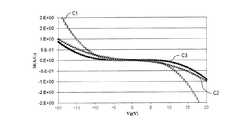
次に、図3を参照しながら、ダイオード素子10の電気特性について説明する。図3は、以下に説明する素子の電圧(V)−電流(I)特性を示すグラフである。図3中の、曲線C1は半導体装置100が有する画素用の酸化物半導体TFTのゲート電圧(V)−電流(I)特性を示す曲線である。曲線C2はダイオード素子10の電圧(V)−電流(I)特性を示す曲線である。曲線C3は、一般的に用いられているアモルファスシリコン(a−Si)層を半導体層として有するショートリング用のダイオード素子(a−Siダイオード素子)の電圧(V)−電流(I)特性を示す曲線である。 Next, the electrical characteristics of the
図3から分かるように、画素用TFTは、印加電圧の絶対値が大きくなると酸化物半導体層の抵抗値が小さくなるので、電流値の絶対値が大きくなってしまう。つまり、酸化物半導体層は移動度が高いことから、高い電圧を印加した場合、半導体層の抵抗値を数MΩ〜数百MΩに調整するのが難しい。従って、画素用TFTのような構成を有するダイオード素子は、ショートリング用のダイオード素子として機能しにくい。一方、ダイオード素子10の電気特性とa−Siダイオード素子の電気特性とを比較すると、曲線C2と曲線C3とは略一致しており、ダイオード素子10がショートリング用のダイオード素子として機能し得ることが分かる。これは、ダイオード素子10がオフセット領域19を有しており、ダイオード素子10の酸化物半導体層5の電気的抵抗が高くなったからである。 As can be seen from FIG. 3, in the pixel TFT, when the absolute value of the applied voltage increases, the resistance value of the oxide semiconductor layer decreases, and thus the absolute value of the current value increases. In other words, since the oxide semiconductor layer has high mobility, it is difficult to adjust the resistance value of the semiconductor layer to several MΩ to several hundred MΩ when a high voltage is applied. Therefore, a diode element having a configuration such as a pixel TFT is unlikely to function as a short ring diode element. On the other hand, when the electrical characteristics of the
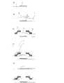
次に、本発明による実施形態における半導体装置100の製造方法を図4および図5を参照しながら説明する。図4は、ダイオード素子10の製造方法を説明する図であり、図5は画素用TFTの製造方法を説明する図である。また、ここで説明するダイオード素子10および画素用TFTは、一連のプロセスで形成される。なお、半導体装置100の製造方法は、以下に説明する方法に限定されない。例えば、国際公開第2012/011258号に開示されている半導体装置の製造方法を用いて、ダイオード素子10を形成することもできる。参考までに、国際公開第2012/011258号の開示内容の全てを本明細書に援用する。 Next, a method for manufacturing the
最初に、ダイオード素子10の製造方法について説明する。 First, a method for manufacturing the
図4(a)に示すように、絶縁基板(例えばガラス基板)1上に、公知の方法で、下層をTi層、上層をCu層とする積層構造を有する第1電極3を形成する。第1電極3は、後述する画素用TFTのゲート電極53と同じ導電膜から形成される。第1電極3の下層の厚さは、例えば30nm〜150nmである。第1電極3の上層の厚さは、例えば200nm〜500nmである。上層は、Cu層の代わりに例えばAl層であってもよく、また、第1電極3は、例えばTi層のみから形成された単層構造を有してもよい。 As shown in FIG. 4A, a
次に、図4(b)に示すように、第1電極3上に、公知の方法で、例えばSiNxを含有する第1絶縁層4を形成する。第1絶縁層4の厚さは、例えば100nm〜500nmである。Next, as shown in FIG. 4B, a first insulating layer 4 containing, for example, SiNx is formed on the
次に、第1絶縁層4上に酸化物半導体膜を公知の方法で形成する。酸化物半導体膜は、例えばa−IGZO膜から形成されている。酸化物半導体膜は、画素用TFTの半導体層を形成する半導体膜から形成されている。酸化物半導体膜の厚さは、例えば50nm〜300nmである。 Next, an oxide semiconductor film is formed on the first insulating layer 4 by a known method. The oxide semiconductor film is formed from, for example, an a-IGZO film. The oxide semiconductor film is formed from a semiconductor film that forms a semiconductor layer of the pixel TFT. The thickness of the oxide semiconductor film is, for example, 50 nm to 300 nm.
次に、酸化物半導体膜を公知の方法でパターニングし、酸化物半導体層5を形成する。 Next, the oxide semiconductor film is patterned by a known method to form the
次に、酸化物半導体層5上に、下層をTi層、上層をCu層とする積層構造を有する導電膜を公知の方法で形成する。導電膜は、後述する画素用TFTのソース電極56と同じ導電膜から形成される。例えば上層は、Cu層の代わりに例えばAl層であってもよく、また、導電膜は、例えばTi層のみから形成された単層構造を有してもよい。下層の厚さは、例えば30nm〜150nmである。上層の厚さは、例えば200nm〜500nmである。 Next, a conductive film having a stacked structure in which the lower layer is a Ti layer and the upper layer is a Cu layer is formed on the
次に、図4(c)に示すように、導電膜を公知の方法でパターニングし、第2電極6および第3電極7を形成する。このとき、オフセット領域19も形成される。絶縁基板1の法線方向から見たとき、オフセット領域19は、第1電極3、第2電極6および第3電極7のいずれとも重ならないように形成される。 Next, as shown in FIG. 4C, the conductive film is patterned by a known method to form the
次に、図4(d)に示すように、第2および第3電極6および7上に第2絶縁層8を公知の方法で形成する。第2絶縁層8は、例えばSiNx(窒化シリコン)から形成される。例えば第2絶縁層8の厚さは、例えば100nm〜500nmである。Next, as shown in FIG. 4D, a second
次に、第2絶縁層8上に公知の方法で感光性の有機絶縁層9を形成する。有機絶縁層9は、例えば感光性のアクリル樹脂から形成される。有機絶縁層9の厚さは、例えば3μmである。 Next, a photosensitive organic
次に、図4(e)に示すように、有機絶縁層9上に、公知の方法で透明電極11を形成する。透明電極11は、例えばITOから形成される。透明電極11の厚さは、例えば50nm〜200nmである。透明電極11を形成することにより、図2(a)に示したように、第1電極3と第2電極6または第3電極7とが、第2絶縁層8および有機絶縁層9に形成されたコンタクトホール内で電気的に接続される。 Next, as shown in FIG. 4E, a
次に、図5(a)〜図5(e)を参照して、画素用TFTの製造方法を説明する。 Next, with reference to FIGS. 5A to 5E, a method for manufacturing a pixel TFT will be described.
図5(a)に示すように、絶縁基板(例えばガラス基板)1上に、公知の方法で、下層をTi層、上層をCu層とする積層構造を有するゲート電極53を形成する。ゲート電極53の大きさは、第1電極3よりも大きい。 As shown in FIG. 5A, a
次に、図5(b)に示すように、ゲート電極53上に、公知の方法で、例えばSiNxを含有する第1絶縁層4を形成する。第1絶縁層4の厚さは、例えば100nm〜500nmである。Next, as shown in FIG. 5B, the first insulating layer 4 containing, for example, SiNx is formed on the
次に、第1絶縁層4上に酸化物半導体膜を公知の方法で形成する。酸化物半導体膜は、例えばa−IGZO膜から形成されている。酸化物半導体膜の厚さは、例えば50nm〜300nmである。 Next, an oxide semiconductor film is formed on the first insulating layer 4 by a known method. The oxide semiconductor film is formed from, for example, an a-IGZO film. The thickness of the oxide semiconductor film is, for example, 50 nm to 300 nm.
次に、酸化物半導体膜を公知の方法でパターニングし、酸化物半導体層55を形成する。 Next, the oxide semiconductor film is patterned by a known method to form the
次に、酸化物半導体層55上に、下層をTi層、上層をCu層とする積層構造を有する導電膜を公知の方法で形成する。上層は、Cu層の代わりに例えばAl層であってもよく、また、導電膜は、例えばTi層のみから形成された単層構造を有してもよい。下層の厚さは、例えば30nm〜150nmである。上層の厚さは、例えば200nm〜500nmである。 Next, a conductive film having a stacked structure in which the lower layer is a Ti layer and the upper layer is a Cu layer is formed over the
次に、図5(c)に示すように、導電膜を公知の方法でパターニングし、ソース電極56およびドレイン電極57を形成する。このとき、ゲート電極53は、第1電極3よりも大きく形成されているので、上述したオフセット領域19は形成されない。 Next, as shown in FIG. 5C, the conductive film is patterned by a known method to form the
次に、図5(d)に示すように、ソース電極56およびドレイン電極57上に第2絶縁層8を公知の方法で形成する。第2絶縁層8は、例えばSiNx(窒化シリコン)から形成される。例えば第2絶縁層8の厚さは、例えば100nm〜500nmである。Next, as shown in FIG. 5D, the second insulating
次に、第2絶縁層8上に公知の方法で感光性の有機絶縁層9を形成する。有機絶縁層9は、例えば感光性のアクリル樹脂から形成される。有機絶縁層9の厚さは、例えば3μmである。 Next, a photosensitive organic
次に、図5(e)に示すように、有機絶縁層9上に、公知の方法で画素電極61を形成する。画素電極61は、透明電極から形成され、例えばITOから形成される。画素電極61の厚さは、例えば50nm〜200nmである。 Next, as shown in FIG. 5E, a
このように、ダイオード素子10と画素用TFTとは少なくとも一部の工程を共通の工程とする製造プロセスによって製造することができる。従って、半導体装置100を効率よく製造できる。 Thus, the
本発明による実施形態の半導体装置およびその製造方法は、上記の例に限られず、静電防止が望まれる場合も含む。 The semiconductor device and the manufacturing method thereof according to the embodiment of the present invention are not limited to the above example, and include cases where electrostatic prevention is desired.
以上、本発明により、酸化物半導体TFTを備える半導体装置において、静電気によるダメージを防ぐことができる半導体装置の製造方法およびそのような製造方法によって製造される半導体装置が提供される。 As described above, the present invention provides a semiconductor device manufacturing method capable of preventing damage due to static electricity in a semiconductor device including an oxide semiconductor TFT, and a semiconductor device manufactured by such a manufacturing method.
本発明は、アクティブマトリクス基板等の回路基板、液晶表示装置、有機エレクトロルミネセンス(EL)表示装置および無機エレクトロルミネセンス表示装置等の表示装置、イメージセンサー装置等の撮像装置、画像入力装置や指紋読み取り装置等の薄膜トランジスタを備えた半導体装置に広く適用できる。 The present invention relates to a circuit substrate such as an active matrix substrate, a liquid crystal display device, a display device such as an organic electroluminescence (EL) display device and an inorganic electroluminescence display device, an imaging device such as an image sensor device, an image input device, and a fingerprint. The present invention can be widely applied to a semiconductor device including a thin film transistor such as a reading device.
1 絶縁基板
3、3a、3b 第1電極
4、8、9 絶縁層
5、5a、5b 酸化物半導体層
6 第2電極
7 第3電極
10、10A、10B ダイオード素子
11 透明電極
19 オフセット領域
100 半導体装置DESCRIPTION OF
Claims (7)
Translated fromJapanese前記絶縁基板上に形成された複数の配線と、
複数の薄膜トランジスタと、
複数のダイオード素子であって、それぞれが前記複数の配線の内の2本の配線を互いに電気的に接続する複数のダイオード素子とを有する半導体装置であって、
前記複数のダイオード素子はそれぞれ、
前記薄膜トランジスタのゲート電極と同一の導電膜から形成された第1電極と、
前記第1電極上に形成された酸化物半導体層と、
前記薄膜トランジスタのソース電極と同一の導電膜から形成され、前記酸化物半導体層と接触する第2電極および第3電極とを有し、
前記酸化物半導体層は、前記第1電極と前記第2電極との間、および、前記第1電極と前記第3電極との間に、それぞれオフセット領域を有し、前記オフセット領域は、前記絶縁基板の法線方向から見たとき、前記第1、第2および第3電極のいずれとも重なっていない、半導体装置。An insulating substrate;
A plurality of wirings formed on the insulating substrate;
A plurality of thin film transistors;
A plurality of diode elements each having a plurality of diode elements that electrically connect two of the plurality of wirings to each other;
Each of the plurality of diode elements is
A first electrode formed of the same conductive film as the gate electrode of the thin film transistor;
An oxide semiconductor layer formed on the first electrode;
A second electrode and a third electrode formed from the same conductive film as the source electrode of the thin film transistor and in contact with the oxide semiconductor layer;
The oxide semiconductor layer has an offset region between the first electrode and the second electrode and between the first electrode and the third electrode, and the offset region is the insulating layer. A semiconductor device which does not overlapany of the first, second and third electrodes when viewed from the normal direction of the substrate.
前記複数のダイオード素子は、2本のソース配線を互いに電気的に接続するダイオード素子および2本のゲート配線を互いに電気的に接続するダイオード素子の少なくとも1つを含む、請求項1から4のいずれかに記載の半導体装置。The plurality of wirings include a plurality of source wirings and a plurality of gate wirings,
Wherein the plurality of diode elements, includes at least one diode element that connects the two electrical diodes and two gate wirings mutually connecting the source wiring electrically to each other, any of claims 1 to4 A semiconductor device according to claim 1.
前記複数のダイオード素子は、2本のソース配線を互いに電気的に接続するダイオード素子、2本のゲート配線を互いに電気的に接続するダイオード素子、ゲート配線と補助容量配線とを互いに電気的に接続するダイオード素子、ソース配線と補助容量配線とを互いに電気的に接続するダイオード素子、補助容量配線と共通電極配線とを互いに電気的に接続するダイオード素子、ゲート配線と共通電極配線とを互いに電気的に接続するダイオード素子、ソース配線と共通電極配線とを互いに電気的に接続するダイオード素子、または2本の検査信号配線を互いに電気的に接続するダイオード素子を含む、請求項1から5のいずれかに記載の半導体装置。The plurality of wirings further includes any of a plurality of auxiliary capacitance wirings, a common electrode wiring, or a plurality of inspection signal wirings,
The plurality of diode elements are diode elements that electrically connect two source lines to each other, diode elements that electrically connect two gate lines to each other, and electrically connect gate lines and auxiliary capacitance lines to each other. A diode element that electrically connects the source wiring and the auxiliary capacitance wiring, a diode element that electrically connects the auxiliary capacitance wiring and the common electrode wiring, and the gate wiring and the common electrode wiring electrically diode element connected to the source lines and the common electrode wiring and electrically connected to a diode element to each other, or a diode for electrically connecting together two test signal lines, one of claims 1 to5 A semiconductor device according to 1.
Priority Applications (1)
| Application Number | Priority Date | Filing Date | Title |
|---|---|---|---|
| JP2013503894AJP5284553B2 (en) | 2011-04-08 | 2012-04-02 | Semiconductor device and display device |
Applications Claiming Priority (4)
| Application Number | Priority Date | Filing Date | Title |
|---|---|---|---|
| JP2011086192 | 2011-04-08 | ||
| JP2011086192 | 2011-04-08 | ||
| JP2013503894AJP5284553B2 (en) | 2011-04-08 | 2012-04-02 | Semiconductor device and display device |
| PCT/JP2012/058867WO2012137711A1 (en) | 2011-04-08 | 2012-04-02 | Semiconductor device and display device |
Publications (2)
| Publication Number | Publication Date |
|---|---|
| JP5284553B2true JP5284553B2 (en) | 2013-09-11 |
| JPWO2012137711A1 JPWO2012137711A1 (en) | 2014-07-28 |
Family
ID=46969111
Family Applications (1)
| Application Number | Title | Priority Date | Filing Date |
|---|---|---|---|
| JP2013503894AActiveJP5284553B2 (en) | 2011-04-08 | 2012-04-02 | Semiconductor device and display device |
Country Status (7)
| Country | Link |
|---|---|
| US (1) | US20140027769A1 (en) |
| EP (1) | EP2755239A4 (en) |
| JP (1) | JP5284553B2 (en) |
| KR (1) | KR101537458B1 (en) |
| CN (1) | CN103460391A (en) |
| TW (1) | TW201248864A (en) |
| WO (1) | WO2012137711A1 (en) |
Families Citing this family (10)
| Publication number | Priority date | Publication date | Assignee | Title |
|---|---|---|---|---|
| US20140297058A1 (en)* | 2013-03-28 | 2014-10-02 | Hand Held Products, Inc. | System and Method for Capturing and Preserving Vehicle Event Data |
| KR102105369B1 (en)* | 2013-09-25 | 2020-04-29 | 삼성디스플레이 주식회사 | Mother substrate for a display substrate, array testing method thereof and display substrate |
| JP6296277B2 (en)* | 2013-10-01 | 2018-03-20 | 株式会社Joled | Display device panel, display device, and display device panel inspection method |
| JP6845980B2 (en)* | 2014-12-17 | 2021-03-24 | 伊東電機株式会社 | Goods storage device and goods moving device |
| CN105789279A (en)* | 2016-03-11 | 2016-07-20 | 深圳市华星光电技术有限公司 | Thin film transistor, liquid crystal display panel and fabrication method of thin film transistor |
| WO2017170219A1 (en)* | 2016-03-31 | 2017-10-05 | シャープ株式会社 | Active matrix substrate, manufacturing method therefor and display device |
| US10147718B2 (en)* | 2016-11-04 | 2018-12-04 | Dpix, Llc | Electrostatic discharge (ESD) protection for the metal oxide medical device products |
| CN107664889B (en)* | 2017-09-14 | 2020-05-22 | 深圳市华星光电半导体显示技术有限公司 | A TFT device and an electrostatic protection circuit for a liquid crystal display panel |
| CN207424484U (en)* | 2017-11-27 | 2018-05-29 | 京东方科技集团股份有限公司 | A kind of array substrate and display device |
| CN109449168B (en)* | 2018-11-14 | 2021-05-18 | 合肥京东方光电科技有限公司 | Conductive structure and method for manufacturing the same, array substrate and display device |
Family Cites Families (19)
| Publication number | Priority date | Publication date | Assignee | Title |
|---|---|---|---|---|
| JP3396620B2 (en)* | 1998-03-20 | 2003-04-14 | シャープ株式会社 | Active matrix substrate and inspection method thereof |
| JP3667548B2 (en) | 1998-03-27 | 2005-07-06 | シャープ株式会社 | Active matrix type liquid crystal display panel and inspection method thereof |
| JP4252528B2 (en) | 1998-03-27 | 2009-04-08 | シャープ株式会社 | Active matrix type liquid crystal display panel and inspection method thereof |
| JP2001024195A (en)* | 1999-07-05 | 2001-01-26 | Nippon Telegr & Teleph Corp <Ntt> | Protection element |
| GB0100733D0 (en)* | 2001-01-11 | 2001-02-21 | Koninkl Philips Electronics Nv | A method of manufacturing an active matrix substrate |
| JP2003043523A (en)* | 2001-08-03 | 2003-02-13 | Casio Comput Co Ltd | Thin film transistor panel |
| JP2003298062A (en) | 2002-03-29 | 2003-10-17 | Sharp Corp | Thin film transistor and method of manufacturing the same |
| KR101133751B1 (en)* | 2003-09-05 | 2012-04-09 | 삼성전자주식회사 | Thin film transistor substrate |
| KR100583421B1 (en)* | 2004-01-29 | 2006-05-24 | 실리콘 디스플레이 (주) | Pixel circuits used in organic light emitting diodes and display devices using them |
| JP5036173B2 (en)* | 2004-11-26 | 2012-09-26 | 株式会社半導体エネルギー研究所 | Method for manufacturing semiconductor device |
| JP2007310131A (en)* | 2006-05-18 | 2007-11-29 | Mitsubishi Electric Corp | Active matrix substrate and active matrix display device |
| JP5305630B2 (en)* | 2006-12-05 | 2013-10-02 | キヤノン株式会社 | Manufacturing method of bottom gate type thin film transistor and manufacturing method of display device |
| JP2009253204A (en) | 2008-04-10 | 2009-10-29 | Idemitsu Kosan Co Ltd | Field-effect transistor using oxide semiconductor, and its manufacturing method |
| JP5406295B2 (en)* | 2009-06-18 | 2014-02-05 | シャープ株式会社 | Semiconductor device |
| JP5728171B2 (en)* | 2009-06-29 | 2015-06-03 | 株式会社半導体エネルギー研究所 | Semiconductor device |
| WO2011013502A1 (en)* | 2009-07-31 | 2011-02-03 | Semiconductor Energy Laboratory Co., Ltd. | Semiconductor device and manufacturing method thereof |
| JP5663231B2 (en)* | 2009-08-07 | 2015-02-04 | 株式会社半導体エネルギー研究所 | Light emitting device |
| CN103026398B (en) | 2010-07-21 | 2014-07-09 | 夏普株式会社 | Substrate and process for production thereof, and display device |
| US9171840B2 (en)* | 2011-05-26 | 2015-10-27 | Semiconductor Energy Laboratory Co., Ltd. | Semiconductor device and manufacturing method thereof |
- 2012
- 2012-04-02CNCN2012800163262Apatent/CN103460391A/enactivePending
- 2012-04-02JPJP2013503894Apatent/JP5284553B2/enactiveActive
- 2012-04-02EPEP12767502.3Apatent/EP2755239A4/ennot_activeWithdrawn
- 2012-04-02KRKR1020137026382Apatent/KR101537458B1/ennot_activeExpired - Fee Related
- 2012-04-02USUS14/110,194patent/US20140027769A1/ennot_activeAbandoned
- 2012-04-02WOPCT/JP2012/058867patent/WO2012137711A1/enactiveApplication Filing
- 2012-04-05TWTW101112093Apatent/TW201248864A/enunknown
Also Published As
| Publication number | Publication date |
|---|---|
| WO2012137711A1 (en) | 2012-10-11 |
| TW201248864A (en) | 2012-12-01 |
| EP2755239A1 (en) | 2014-07-16 |
| KR101537458B1 (en) | 2015-07-16 |
| JPWO2012137711A1 (en) | 2014-07-28 |
| EP2755239A4 (en) | 2015-06-10 |
| US20140027769A1 (en) | 2014-01-30 |
| CN103460391A (en) | 2013-12-18 |
| KR20140012712A (en) | 2014-02-03 |
Similar Documents
| Publication | Publication Date | Title |
|---|---|---|
| JP5284553B2 (en) | Semiconductor device and display device | |
| US11563039B2 (en) | Display device | |
| KR102141557B1 (en) | Array substrate | |
| KR102098220B1 (en) | Display Panel For Display Device | |
| CN104170069B (en) | Semiconductor device and manufacturing method thereof | |
| CN104205341B (en) | Semiconductor device and its manufacture method | |
| CN106886107B (en) | Display panel | |
| US10522567B2 (en) | Semiconductor device and display device having a protection layer | |
| CN102184967A (en) | Thin film transistor | |
| CN104094409B (en) | Semiconductor device and manufacturing method thereof | |
| US20190221590A1 (en) | Active matrix substrate and display device provided with active matrix substrate | |
| US10503035B2 (en) | Display device | |
| CN104247031B (en) | Semiconductor device and manufacturing method thereof | |
| CN105304720A (en) | Thin film transistor | |
| JP2019078862A (en) | Active matrix substrate and method for manufacturing the same | |
| US8835928B2 (en) | Semiconductor device and process for production thereof | |
| CN104380474B (en) | Semiconductor device and its manufacture method | |
| CN104465784A (en) | Thin film transistor and display panel |
Legal Events
| Date | Code | Title | Description |
|---|---|---|---|
| TRDD | Decision of grant or rejection written | ||
| A01 | Written decision to grant a patent or to grant a registration (utility model) | Free format text:JAPANESE INTERMEDIATE CODE: A01 Effective date:20130507 | |
| A61 | First payment of annual fees (during grant procedure) | Free format text:JAPANESE INTERMEDIATE CODE: A61 Effective date:20130529 | |
| R150 | Certificate of patent or registration of utility model | Ref document number:5284553 Country of ref document:JP Free format text:JAPANESE INTERMEDIATE CODE: R150 |