JP5281503B2 - Electrode structure for enzyme sensor, enzyme sensor, and artificial pancreas device - Google Patents
Electrode structure for enzyme sensor, enzyme sensor, and artificial pancreas deviceDownload PDFInfo
- Publication number
- JP5281503B2 JP5281503B2JP2009156820AJP2009156820AJP5281503B2JP 5281503 B2JP5281503 B2JP 5281503B2JP 2009156820 AJP2009156820 AJP 2009156820AJP 2009156820 AJP2009156820 AJP 2009156820AJP 5281503 B2JP5281503 B2JP 5281503B2
- Authority
- JP
- Japan
- Prior art keywords
- enzyme
- electrode
- layer
- sensor
- working electrode
- Prior art date
- Legal status (The legal status is an assumption and is not a legal conclusion. Google has not performed a legal analysis and makes no representation as to the accuracy of the status listed.)
- Expired - Fee Related
Links
Images


Landscapes
- External Artificial Organs (AREA)
Description
Translated fromJapaneseこの発明は、酵素センサ用電極構造体、酵素センサ及び人工膵臓装置に関し、さらに詳しくは、作用極上に酵素層を所定の面積をもって均一な厚みで形成してなり、作用極上に流通抵抗なく試料液を流通させることができる酵素センサ用電極構造体、この酵素センサ用電極構造体を備えて成る酵素センサ、及びこの酵素センサを備えて成る人工膵臓装置に関する。 The present invention relates to an electrode structure for an enzyme sensor, an enzyme sensor, and an artificial pancreas device. More specifically, an enzyme layer is formed on the working electrode with a predetermined area and a uniform thickness, and the sample solution has no flow resistance on the working electrode. The present invention relates to an electrode structure for an enzyme sensor that can circulate, an enzyme sensor comprising the electrode structure for an enzyme sensor, and an artificial pancreas device comprising the enzyme sensor.
従来の酵素センサーとしては、例えば非特許文献1に開示されたものが知られている。すなわち、非特許文献1には「・・・グルタミン酸の検出にはグルタミン酸酸化酵素を用いて酸化し、生成した過酸化水素を検出する。反応には酸素が必要なので、基質濃度が高い場合は注意を要する。生成した過酸化水素は通常、白金電極を用い500mV(銀/塩化銀参照電極に対して)程度の電位を印加すると容易に検出することができる。我々のセンサーではHellerらにより合成されたオスミウム−ポリビニルピリジン錯体高分子(Os-gel)と西洋ワサビペルオキシターゼ(HRP)により過酸化水素を検出する。・・・まず、炭素電極にHRPを含むOs-gel溶液を導入し、溶媒蒸発法により薄膜を形成する。乾燥後、酵素を牛血清アルブミンと混合し、グルタルアルデヒド(架橋剤)と混合した後Os-gel膜上に導入して、酵素膜を形成する。酵素を修飾した電極は・・・」という構造が提案されている。 As a conventional enzyme sensor, for example, one disclosed in Non-Patent
一方、現在の医療現場において、例えば患者の血糖値を測定するグルコースセンサとして、円筒形をしたセンサ本体の先端面に、白金から成る作用電極と銀/塩化銀から成る参照電極とを露出させ、それら作用電極及び参照電極を酵素膜で被覆し、更に前記センサ本体の先端面を蓋体で覆蓋して試料流通室を着脱自在に形成するとともに前記蓋体に試料を前記試料流通室に導入する試料導入路及び前記試料流通室から試料を導出する試料導出路を備えて成るフローセルタイプのものが知られている。 On the other hand, in the current medical field, for example, as a glucose sensor for measuring a blood glucose level of a patient, a working electrode made of platinum and a reference electrode made of silver / silver chloride are exposed on the front end surface of a cylindrical sensor body, The working electrode and the reference electrode are covered with an enzyme film, and the tip end surface of the sensor body is covered with a lid to form a sample circulation chamber so as to be detachable, and a sample is introduced into the lid in the sample circulation chamber There is known a flow cell type that includes a sample introduction path and a sample lead-out path for leading a sample from the sample flow chamber.
また、バイオセンサー等の電気化学検出センサーとして使用されるプレナー型電極が、特許文献1にて提案されている。 Further,
この特許文献1にて提案されている発明は「絶縁基板上に導電パターンにより形成された電極において、前記電極は少なくとも電気化学的な信号を測定するための作用電極を有し、前記作用電極に溶液を滴下することにより溶液に含まれる材料が固定化される電極であって、前記溶液を作用電極に積極的に留まらせるために、作用電極の中心から外側に向かって前記溶液に対して相対的に親和性の高い領域と低い領域とをこの順に配置し、前記一方の領域と前記他方の領域とで形成される境界線が前記溶液が滴下される作用電極の周囲に半分以上存在していることを特徴とするプレナー型の電極」である(特許文献1の請求項1参照)。 The invention proposed in
このプレナー型の電極の一実施形態として「絶縁被膜3の一部3aを、絶縁被膜3から完全に分離して、完全な円環状のダム4として、作用電極J1の周囲に配置」した印刷電極1が、特許文献1に開示されている(特許文献1の段落番号0023、図3(a)、(b)、(c)参照)。このダム4は、「作用電極J1上に、極性溶液を滴下した場合、上記絶縁被膜3の一部3aを作用電極J1の周囲に配するものと比べ、溶液を更に安定した状態で作用電極上に固定できるように」する機能を有する(特許文献1の段落番号0023参照)。また、ダム5は、「滴下した溶液 がコネクタとの接続部分にまで達するのを防げる」機能を有するように形成される(特許文献1の段落番号0026参照)。 As an embodiment of this planar electrode, “a part 3a of the insulating coating 3 is completely separated from the insulating coating 3 and arranged around the working electrode J1 as a complete
以上に説明したように、特許文献1に開示されている「ダム」は、滴下した溶液が作用極以外に広がらないようにする機能を有しているが、ダム内に溶液を入れると溶液の液面が凸状に盛り上がる。そして溶液の溶媒が揮散することにより固化すると凸状の湾曲固化面が形成されてしまう。そうすると、作用極の中心部と周縁部とでは膜厚が相違することになり、試料の測定中に、気泡が作用極の表面に付着し易くなる。気泡が作用極の表面に付着すると、測定値が不安定かつ不正確になる。この問題点は、前記非特許文献1に記載された酵素膜を前記グルコースセンサに適用しても解決されない。 As described above, the “dam” disclosed in
非特許文献2には、ICUに収容されている重症患者の血糖値を80〜110mg/dLに制御する強化インスリン療法を実施することで、それまで約20%であった死亡率を10%程度にまで低減できることが報告されている。すなわち、患者の血糖値を正確に管理することは極めて重要であって、そのためには患者の血糖値を安定して正確に測定することができるグルコースセンサが必要である。
この発明者らは、前記課題の下に、新規な電極構造体を開発するべく研究を重ねた。その結果として、基板上に対極、参照極及び作用極を形成してなる酵素センサ用電極構造体を案出したが、作用極として作用電極上に酵素溶液を塗布しこれを乾燥固化することにより作用電極上に酵素層を形成するのでは、均一な層厚を有する所定面積をもった酵素層を形成することができないという問題点に遭遇した。 Under these problems, the inventors have conducted research to develop a novel electrode structure. As a result, an electrode structure for an enzyme sensor having a counter electrode, a reference electrode, and a working electrode formed on a substrate has been devised. By applying an enzyme solution on the working electrode as a working electrode and drying and solidifying it. When the enzyme layer is formed on the working electrode, a problem has been encountered that an enzyme layer having a uniform area and a predetermined area cannot be formed.
この発明は、このような問題点を解消し、均一な層厚を有する所定面積の酵素層を備えた作用極を有する酵素センサ用電極構造体を提供すること、この酵素センサ用電極構造体を備えた酵素センサを提供すること、及びこの酵素センサを備えた人工膵臓装置を提供することをその課題とする。 The present invention eliminates such problems and provides an electrode structure for an enzyme sensor having a working electrode provided with an enzyme layer having a predetermined area having a uniform layer thickness. It is an object of the present invention to provide an enzyme sensor equipped with the device and to provide an artificial pancreas device equipped with the enzyme sensor.
上記課題を解決するための手段として、
請求項1は、
基板上に作用極及び参照極を備えて成る酵素センサ用電極構造体であって、
前記作用極は、前記基板上に形成された電極層と、前記電極層上に形成された酵素層と、前記電極層及び前記酵素層を囲繞する堰堤部とを備え、
前記堰堤部は、前記酵素層を形成する以前において前記酵素層の原料である酵素溶液をこの堰堤部に収容したときにその酵素溶液の表面を水平に維持しつつその酵素溶液を保持可能に形成して成り、
前記堰堤部は前記電極層に臨む縁庇部を有し、その縁庇部は、毛細管現象により酵素溶液の進入を許容する溶液浸入部を有することを特徴とする酵素センサ用電極構造体であり、
請求項2は、
前記請求項1に記載の酵素センサ用電極構造体を内蔵するセルと、前記セル内に試料液を導入する液導入口と、前記測定済みの試料液を排出する液導出口とを備えて成ることを特徴とする酵素センサであり、
請求項3は、
前記試料液がグルコースを含有して成り、前記作用極が、電極層上に形成された金属錯体含有ポリマー及びペルオキシダーゼを含有する第1酵素層、及び、前記第1酵素層上に形成され、グルコースを酸化して過酸化水素を生成する酵素を含有する第2酵素層を積層一体化して成る、人工膵臓用センサである前記請求項2に記載の酵素センサであり、
請求項4は、
前記対極が、前記基板上で、前記作用極に対して間隔を設けて前記作用極を囲繞するように配置形成されて成る前記請求項2又は3に記載の酵素センサであり、
請求項5は、
前記請求項2〜4のいずれか1項に記載の酵素センサを備える人工膵臓装置である。
As means for solving the above problems,
An electrode structure for an enzyme sensor comprising a working electrode and a reference electrode on a substrate,
The working electrode includes an electrode layer formed on the substrate, an enzyme layer formed on the electrode layer, and a dam portion surrounding the electrode layer and the enzyme layer,
The dam portion is formed so as to be able to hold the enzyme solution while maintaining the surface of the enzyme solution horizontally when the enzyme solution, which is a raw material of the enzyme layer, is accommodated in the dam portion before the enzyme layer is formed. It was madeby,
The dam portion has an edge portion facing the electrode layer, and the edge portion has a solution intrusion portion that allows entry of the enzyme solution by capillary action . ,
A cell containing the enzyme sensor electrode structure according to
Claim3
The sample solution contains glucose, and the working electrode is formed on the first enzyme layer containing the metal complex-containing polymer and peroxidase formed on the electrode layer, and on the first enzyme layer, and glucose The enzyme sensor according to
The enzyme sensor according to claim2 or 3 , wherein the counter electrode is disposed and formed on the substrate so as to surround the working electrode at a distance from the working electrode.
Claim5
It is an artificial pancreas apparatus provided with the enzyme sensor of any one of the said Claims2-4 .
この発明に係る酵素センサ用電極構造体における作用極は、作用電極の縁辺部に形成された堰堤部によって、酵素溶液が盛り上がった状態であるドーム型を維持したまま酵素層が形成されることがなく、酵素層が平坦となった状態に形成される。したがって、この酵素センサ用電極構造体に試料液を流通させた場合に、作用電極の表面がドーム状に盛り上がることによる流通抵抗がなくなり、試料液が作用電極上を流通抵抗なく流通することができるようになる。したがって、酵素層上を試料液を通過する際に気泡が酵素層上に付着する現象が発生し難くなり、酵素層による測定値にバラツキが小さくなる。酵素層がドーム状に湾曲することなく平坦な露出面となるので、量産時のセンサ出力電流のバラツキが大幅に減少する。また、酵素層の膜厚が均一になるので、酵素膜中に試料溶液が拡散する速度が一定になり、したがって正確な測定を行うことができる。要するに、作用電極表面に、一定の厚み及び一定の表面積の酵素層が形成されて成るので、この酵素センサ用電極構造体が安定した応答性を示す迄の時間が短くなり、安定した出力を実現することができる。 In the working electrode in the electrode structure for an enzyme sensor according to the present invention, an enzyme layer may be formed while maintaining a dome shape in which the enzyme solution is raised by a dam portion formed at the edge of the working electrode. The enzyme layer is formed in a flat state. Therefore, when the sample liquid is circulated through the electrode structure for enzyme sensor, the flow resistance due to the surface of the working electrode rising in a dome shape is eliminated, and the sample liquid can flow on the working electrode without the flow resistance. It becomes like this. Therefore, it is difficult for the phenomenon of bubbles to adhere to the enzyme layer when passing through the sample solution on the enzyme layer, and the measurement value of the enzyme layer is less varied. Since the enzyme layer becomes a flat exposed surface without bending in a dome shape, the variation in sensor output current during mass production is greatly reduced. In addition, since the thickness of the enzyme layer becomes uniform, the rate at which the sample solution diffuses into the enzyme film becomes constant, and therefore accurate measurement can be performed. In short, an enzyme layer with a constant thickness and a constant surface area is formed on the surface of the working electrode, so the time required for the enzyme sensor electrode structure to show a stable response is shortened and a stable output is achieved. can do.
この発明に係る酵素センサ用電極構造体は、前記作用極及び参照極の外に、対極を有することもある。 The enzyme sensor electrode structure according to the present invention may have a counter electrode in addition to the working electrode and the reference electrode.
この酵素センサ用電極構造体を酵素センサに組み込んでなる酵素センサにおいては、液導入口からセル内に試料液を導入すると、セルを形成する内部表面に形成された導電層に電気的に接続された作用極及び参照極に試料液が接触し、作用極における酵素層により、試料液中に含まれる測定対象物質が分解されて、その結果、作用極と、参照電極及び/又は対極との間に、試料液中の測定対象成分の濃度に比例した電流が流れる。この電流値を測定することにより、試料液中の測定対象成分の濃度を算出することができる。 In an enzyme sensor in which this electrode structure for an enzyme sensor is incorporated into an enzyme sensor, when a sample liquid is introduced into the cell from the liquid inlet, it is electrically connected to a conductive layer formed on the inner surface forming the cell. The sample solution comes into contact with the working electrode and the reference electrode, and the measurement target substance contained in the sample solution is decomposed by the enzyme layer at the working electrode. As a result, the working electrode and the reference electrode and / or the counter electrode In addition, a current proportional to the concentration of the component to be measured in the sample solution flows. By measuring this current value, the concentration of the component to be measured in the sample solution can be calculated.
この酵素センサに組み込まれる酵素センサ用電極構造体における酵素層には、作用電極において酸化還元を起こすことのできる分子を測定対象物質から生成させる酵素が含まれる。この酵素層における酵素とこの酵素により分解される測定対象物質との組合せとしては、グルタミン酸を測定対象物質とするときの酵素としてグルタミン酸酸化酵素又はグルタミン酸ジヒドロゲナーゼ、アセチルコリンを測定対象物質とするときの酵素としてコリン酸化酵素及びカタラーゼ、又はグルタミン酸酸化酵素及びカタラーゼ、グルコースを測定対象物質とするときの酵素としてグルコースオキシダーゼ等を例示することができる。 The enzyme layer in the electrode structure for an enzyme sensor incorporated in the enzyme sensor includes an enzyme that generates a molecule capable of causing redox in the working electrode from the measurement target substance. As a combination of an enzyme in this enzyme layer and a measurement target substance decomposed by this enzyme, an enzyme when glutamic acid oxidase or glutamate dihydrogenase or acetylcholine is a measurement target substance as an enzyme when glutamic acid is the measurement target substance As examples, choline oxidase and catalase, glutamate oxidase and catalase, glucose oxidase and the like can be exemplified as an enzyme when glucose is a substance to be measured.
この発明によると、酵素センサにこの発明に係る酵素センサ用電極構造体が組み込まれており、その酵素センサ用電極構造体における酵素層がドーム状に突出することなくその厚みが均一であり、酵素層の表面が堰堤部の囲繞された範囲に限定されているので、酵素層に一定の表面積を確保することができるので、測定対象物質についての安定した作用電極出力を得ることができ、正確に測定対象物質の濃度を測定することのできる酵素センサを提供することが、できる。 According to the present invention, the enzyme sensor electrode structure according to the present invention is incorporated in the enzyme sensor, and the enzyme layer in the enzyme sensor electrode structure has a uniform thickness without protruding in a dome shape. Since the surface of the layer is limited to the enclosed area of the dam part, a certain surface area can be ensured in the enzyme layer, so that a stable working electrode output for the substance to be measured can be obtained and accurately An enzyme sensor that can measure the concentration of a substance to be measured can be provided.
特に、作用極を、電極層上に形成された金属錯体含有ポリマー及びペルオキシダーゼを含有する第1酵素層、及び、前記第1酵素層上に形成され、グルコースを酸化して過酸化水素を生成する酵素を含有する第2酵素層を積層一体化して成る構造にすると、試料液中のグルコース濃度を正確に測定することができるので、この発明によると、グルコースを正確に測定することのできる人工膵臓用センサとしての酵素センサを提供することができる。更に、この発明によると、グルコースを正確に測定することのできる人工膵臓装置も提供することができる。 In particular, the working electrode is formed on the first enzyme layer containing the metal complex-containing polymer and peroxidase formed on the electrode layer, and on the first enzyme layer, and oxidizes glucose to generate hydrogen peroxide. When the second enzyme layer containing the enzyme is laminated and integrated, the glucose concentration in the sample solution can be accurately measured. According to the present invention, the artificial pancreas that can accurately measure glucose An enzyme sensor can be provided as an industrial sensor. Furthermore, according to this invention, the artificial pancreas apparatus which can measure glucose correctly can also be provided.
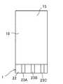
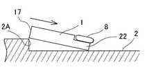
この発明の酵素センサの一例としての人工膵臓用センサを図1に示す。図1に示されるように、この発明の一例である人工膵臓用センサ1は、人工膵臓装置(図示せず。)における基台2に着脱自在に装着される。基台2は、人工膵臓用センサ1で検出されるグルコースを含有する試料液を導出する導出路3及びその開口部である導出開口部4と、前記人工膵臓用センサ1で測定済みの試料液を受け入れる導入路5及びその開口部である導入開口部6と、人工膵臓用センサ1でグルコースを測定することにより生じる電流を取り出す導電層と電気的に接続する電気コネクタ7とを有する。 FIG. 1 shows an artificial pancreas sensor as an example of the enzyme sensor of the present invention. As shown in FIG. 1, an
この例においては、基台2には、前記導出開口部4と前記導入開口部6とが所定の間隔を有して並んで開口する垂直面部2Aが設けられ、この垂直面部2Aから水平方向に向かって所定の間隔を有してコネクタ部8が配設される。前記垂直面部2Aと前記コネクタ部8との間隔は、この垂直面部2Aと前記コネクタ部8との間に人工膵臓用センサ1を嵌め込むことができるように設計される(図5〜6参照)。 In this example, the
このコネクタ部8は、基台2の表面から所定の間隔を有して基台2の表面上に配置され、しかも弾発的に基台2の表面に対して上下動可能に形成される。このコネクタ部8を弾発的に上下動可能に形成する手段としては、適宜の付勢部材例えばコイルスプリング等を利用して形成することができる。このコネクタ部8の下面には、電気コネクタ7が形成される。 The
図1〜図3に示されるように、前記人工膵臓用センサ1は、筐体10とこの内部に設けられた作用極11、参照極12及び対極13とを有する。 As shown in FIGS. 1 to 3, the
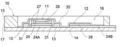
図4に示されるように、前記筐体10は基板14を有し、図3及び図4に示されるように、この基板14と、この基板14を覆蓋する覆蓋体15とで内部にセル16が形成される。この筐体10の一端面は、前記基台2における垂直面部2Aと面接触可能に垂直な平面に形成される。図3及び図4に示されるように、この一端面を垂直端面部17と称することにする。図3に示されるように、この垂直端面部17には、前記導出開口部4に液密に装着可能な液導入口18と、前記導入開口部6に液密に装着可能な液導出口19とが形成される。この液導入口18及び液導出口19それぞれは、連通路20A,20Bにより前記セル16内に連通する。 As shown in FIG. 4, the
前記導出開口部4と液導入口18とを液密に装着する手段としては、例えば導出開口部4を前記垂直面部2Aから突出させ、この突出する導出開口部4を前記液導入口18に挿入し、前記液導入口18の内周面とこの液導入口18に挿入された前記導出開口部4の外周面とを、例えばOリング21等のシール部材で液密にシールする手段を採用することができ、またこの手段以外にも適宜の液密シール手段を採用することもできる。 As means for mounting the
図3に示されるように、この筐体10における、前記垂直端面部17とは反対側の端部には、コネクタ電極形成用の突出板部22が、前記垂直端面部17から離れるように延在形成される。 As shown in FIG. 3, a projecting
この突出板部22は、この人工膵臓用センサ1を基台2に装着すると、図5に示されるように、前記コネクタ部8と基台2の上面とに挟まれる。この突出板部22の上面には、図3に示されるように、コネクタ電極23A,23B,23Cが設けられ、この突出板部22を前記コネクタ部8と基台2の上面との間隙に挿入すると、コネクタ部8に形成された三本の電気コネクタ7とコネクタ電極23A,23B,23Cとが電気的に接続するように形成されている。 When the
なお、この筐体10を形成する材質については、この発明の目的を達成することができる限り特に制限がなく、プラスチック、金属、セラミック等が適宜に採用される。 The material forming the
図3及び図4に示されるように、前記筐体10の内部に存在するセル16の内部表面には、この発明の一例である酵素センサ用電極構造体が設けられる。図4に示されるように、この酵素センサ用電極構造体として、基板14の表面に、作用極11、参照極12及び対極13が設けられる。基板14を形成する材料は、例えば、ポリエチレン、ポリエチレンテレフタレート等のプラスチック、セラミックス、ガラス、紙等の絶縁性を有する材料である。 As shown in FIGS. 3 and 4, an electrode structure for an enzyme sensor which is an example of the present invention is provided on the inner surface of the
図4に示されるように、作用極11は、セル16の内部表面、この例では基板14の床面に形成された堰堤部31の内側であって、前記床面に形成された配線パターン24Aの上面に形成された作用極用の電極25(以下において作用極用電極と称する。)と、第1酵素層26と第2酵素層27とをこの順に積層して成る。作用極11は、図3に示される例では、円盤型に形成された作用極用電極25、この作用極用電極25の上面に円盤型に形成された第1酵素層26及びこの第1酵素層26の表面に形成された第2酵素層27を有し、全体として円盤型に形成されて成る。 As shown in FIG. 4, the working
参照極12と対極13は、それぞれ配線パターン24Bとその上に形成された参照極用電極28、配線パターン24Cとその上に形成された対極用電極29からなる。これら参照極12と対極13の詳細については後述する。 Each of the
前記配線パターン24A〜24Cは低抵抗材料で形成されることができ、この低抵抗材料としては例えば、炭素、銀、銅、白金等を挙げることができる。この配線パターン24A〜24Cは、基板14の表面に印刷法、めっき法、蒸着法、エッチング法、スパッタリング法等により、形成されることができる。その厚みは、通常、5〜100μm程度である。配線パターンの厚みがこの範囲内であると、電気抵抗を低く抑えつつ、通電が可能である。これら配線パターン24A〜24Cは、それぞれコネクタ電極23A〜23Cに電気的に連絡する。 The
この発明に係る酵素センサ用電極構造体において、前記作用極用電極25、参照極用電極28及び対極用電極29の材質としては、導電性材料であって、試料液に接触しても変質等することなく、安定した電位が得られる材料であればよく、例えば、アルミニウム、ニッケル、銅、白金、金及び銀等の金属、ITO等の導電性金属酸化物、炭素及びカーボンナノチューブ等の炭素材料が挙げられる。これらの中でも炭素材料は、そのペーストをスクリーン印刷することにより、対極層13を容易に作成することができる特長を有する。この作用極用電極25の厚みは、通常、5〜100μm程度であることが好ましい。作用極用電極25の厚みがこの範囲内であると、電気抵抗を低く抑えつつ、確実に電流を測定することができる。 In the electrode structure for an enzyme sensor according to the present invention, the working
図3及び図4に示される酵素センサ用電極構造体においては、酵素層は前記第1酵素層26及び第2酵素層27の積層構造体となっているダブル酵素構造が採用されている。もっとも、この発明に係る酵素センサ用電極構造体にあっては、酵素層は、一層の酵素層であっても良い。図3及び図4に示される酵素センサ用電極構造体にあっては、前記第1酵素層26は、前記作用極用電極25の、配線パターン24Aに向う表面とは反対側の表面に形成される。この第1酵素層26は、金属錯体含有ポリマー及び酸化酵素例えばペルオキシダーゼを含有する第1酵素層形成液を、例えば、マイクロシリンジ等で滴下し、その後蒸発させることにより薄い膜状に形成する方法等により形成されることができる。ペルオキシダーゼとしては、例えば、西洋ワサビペルオキシダーゼ等を挙げることができる。 In the enzyme sensor electrode structure shown in FIGS. 3 and 4, the enzyme layer employs a double enzyme structure in which the
金属錯体含有ポリマーとしては、ペルオキシダーゼから電子を受け取り、作用極用電極に電子を放出する機能、つまり酸化還元機能を有する金属錯体を結合するポリマーを挙げることができる。この金属錯体とポリマーとの結合は、共有結合であってもよく、又配位結合であってもよい。金属錯体含有ポリマーを容易に製造することを目的とするのであれば、ポリマーと金属錯体との結合は配位結合であるのが好ましい。配位結合によりポリマーと金属錯体とが結合するためには、配位子が必要であり、換言すると配位原子が必要である。配位原子としては通常、窒素原子、硫黄原子及び酸素原子等を挙げることができる。また配位子としてはアミノ基、フォスフォノ基及びカルボキシル基等を挙げることができる。 Examples of the metal complex-containing polymer include a polymer that binds a metal complex having a function of receiving electrons from peroxidase and releasing electrons to the working electrode, that is, a redox function. The bond between the metal complex and the polymer may be a covalent bond or a coordinate bond. If the purpose is to easily produce a metal complex-containing polymer, the bond between the polymer and the metal complex is preferably a coordination bond. In order to bond the polymer and the metal complex by coordination bond, a ligand is necessary, in other words, a coordination atom is necessary. As a coordination atom, a nitrogen atom, a sulfur atom, an oxygen atom, etc. can be mentioned normally. Examples of the ligand include an amino group, a phosphono group, and a carboxyl group.
このような配位原子又は配位子を備えたポリマーとして、ポリビニルイミダゾール及びポリピロール等の、ローンペア電子を有する窒素原子を有する原子団を側鎖に備えたポリビニルポリマー等を挙げることができる。前記ポリマーの分子量としては、製膜可能である限り特に制限がなく、通常の場合約10000〜100000である。 Examples of the polymer having such a coordination atom or ligand include a polyvinyl polymer having a side chain with an atomic group having a nitrogen atom having a loan pair electron, such as polyvinylimidazole and polypyrrole. The molecular weight of the polymer is not particularly limited as long as it can be formed into a film, and is usually about 10,000 to 100,000.
一方、前記ポリマーに配位結合可能な金属錯体としては、例えば、ジピリジニウムオスミウム等のジピリジニウム等を配位子とするとともに第8族の中心金属イオンを有するオスミウム錯体、フェリシ二ウムイオン又はヘキサシアノ鉄(III)イオンの形成可能な錯体、ヘキサシアノ鉄(III)カリウム、フェロセン、若しくはメチレンブルー等を挙げることができる。前記ポリマーにおける配位原子に配位する金属錯体の前記ポリマー中に含有される量は、理想的には配位原子に対応する量である。 On the other hand, examples of the metal complex capable of coordinate bonding to the polymer include, for example, an osmium complex, ferricium ion, or hexacyanoiron having, as a ligand, dipyridinium such as dipyridinium osmium and a
この発明においては、特に好適な金属錯体含有ポリマーとして、例えば、以下の式(1)で示されるオスミウムポリマーを挙げることができる。 In this invention, as a particularly suitable metal complex-containing polymer, for example, an osmium polymer represented by the following formula (1) can be exemplified.

この発明に係る酵素センサ用電極構造体における酵素層、又は図3及び図4に示される前記第2酵素層は、酵素又は酵素及びメディエータを固定化した膜である。固定化される酵素は、測定される生体物質等に応じて選択される。例えば、測定される生体物質等がアルコールであるときにはアルコールオキシダーゼ、前記生体物質等がグルコースであるときにはβ−D−グルコースオキシダーゼ、前記生体物質等がコレステロールであるときにはコレステロールオキシダーゼ、前記生体物質等がホスファチジルコリンであるときにはホスホリパーゼ及びコリンオキシダーゼ、前記生体物質等が尿素であるときにはウレアーゼ、前記生体物質等が尿酸であるときにはウリカーゼ、前記生体物質等が乳酸であるときには乳酸デヒドロゲナーゼ、前記生体物質等がシュウ酸であるときにはシュウ酸デカルボキシラーゼ、前記生体物質等がピルビン酸であるときにはピルビン酸オキシダーゼ、前記生体物質等がアスコルビン酸であるときにはアスコルビン酸オキシダーゼ、前記生体物質等がトリメチルアミンであるときにはフラビン含有モノオキシダーゼ等が選択される。このバイオセンサチップは、例えばβ−D−グルコースオキシダーゼが選択されたグルコースセンサとして構成されている。 The enzyme layer in the electrode structure for an enzyme sensor according to the present invention or the second enzyme layer shown in FIGS. 3 and 4 is a membrane on which an enzyme or an enzyme and a mediator are immobilized. The enzyme to be immobilized is selected according to the biological material to be measured. For example, alcohol oxidase when the biological substance or the like to be measured is alcohol, β-D-glucose oxidase when the biological substance or the like is glucose, cholesterol oxidase when the biological substance or the like is cholesterol, and the biological substance or the like is phosphatidylcholine. Phospholipase and choline oxidase, urease when the biological material or the like is urea, uricase when the biological material or the like is uric acid, lactate dehydrogenase when the biological material or the like is lactic acid, and the biological material or the like is oxalic acid. In some cases, oxalate decarboxylase, pyruvate oxidase when the biological material or the like is pyruvate, and ascorbate oxidase or the biomaterial when the biological material or the like is ascorbic acid. Flavin-containing mono-oxidase is selected when substances are trimethylamine. This biosensor chip is configured as a glucose sensor in which, for example, β-D-glucose oxidase is selected.
固定化されるメディエータは、フェロセン誘導体、1,4−ベンゾキノン、テトラチアフルバレン、フェリシニウムイオン、ヘキサシアノ鉄(III)イオン、ヘキサシアノ鉄酸カリウム、メチレンブルー等の酸化還元可能な導電性物質が挙げられる。 Examples of the mediator to be immobilized include conductive materials capable of redox such as ferrocene derivatives, 1,4-benzoquinone, tetrathiafulvalene, ferricinium ions, hexacyanoiron (III) ions, potassium hexacyanoferrate, and methylene blue.
酵素及び/又はメディエータ(以下、酵素等という。)を固定する固定化方法として、例えば、担体結合法、架橋法及び包括法等が挙げられる。担体結合法は、水不溶性の担体に酵素等を結合して固定化する方法であり、例えば、共有結合法、イオン結合法、物理吸着法等が挙げられる。架橋法は、酵素等を2個以上の官能基を有する試薬(架橋剤)と反応させて酵素と酵素等とを架橋することによって固定化する方法である。包括法は、酵素等をゲル等の微細な格子の中に包み込む方法、半透膜性の高分子の皮膜によって酵素等を被覆する方法である。 Examples of the immobilization method for immobilizing an enzyme and / or a mediator (hereinafter referred to as an enzyme or the like) include a carrier binding method, a cross-linking method, a comprehensive method, and the like. The carrier binding method is a method in which an enzyme or the like is bound to and immobilized on a water-insoluble carrier, and examples thereof include a covalent bonding method, an ionic bonding method, and a physical adsorption method. The cross-linking method is a method of immobilizing an enzyme by reacting it with a reagent having two or more functional groups (cross-linking agent) to cross-link the enzyme and the enzyme. The entrapment method is a method of wrapping an enzyme or the like in a fine lattice such as a gel, or a method of coating the enzyme or the like with a semipermeable membrane.
担体結合法に用いられる担体としては、水不溶性の高分子材料であれば特に限定されず、例えば、メチルセルロース、エチルセルロース、ヒドロキシエチルセルロース、カルボキシメチルセルロース、セルローズアセテート等の多糖類の誘導体、多孔質ポリウレタン、ポリビニルアルコール、アルギン酸金属塩、ポリアクリル酸ナトリウム、ポリエチレンオキサイド等が挙げられる。架橋法に用いられる架橋剤としては、2個以上の官能基を有する試薬であればよく、例えば、グルタルアルデヒド、イソシアナート誘導体、ビスジアゾベンジン等が挙げられる。包括法に用いられる高分子化合物としては、例えば、ポリアクリルアミド、ポリビニルアルコール等が挙げられる。 The carrier used in the carrier binding method is not particularly limited as long as it is a water-insoluble polymer material. For example, polysaccharide derivatives such as methyl cellulose, ethyl cellulose, hydroxyethyl cellulose, carboxymethyl cellulose, and cellulose acetate, porous polyurethane, polyvinyl Examples include alcohol, metal alginate, sodium polyacrylate, polyethylene oxide and the like. The cross-linking agent used in the cross-linking method may be any reagent having two or more functional groups, and examples thereof include glutaraldehyde, isocyanate derivatives, and bisdiazobenzines. Examples of the polymer compound used in the inclusion method include polyacrylamide and polyvinyl alcohol.
固定化される酵素量は、酵素の種類や用途に応じて任意に設定される。また、担体結合法及び包括法においても、担体及びゲル等に含まれる酵素量は、同様に任意に設定される。酵素量は、例えば、形成される酵素膜の全質量に対して、0.02〜4質量%程度、好ましくは、0.02〜0.2質量%程度である。 The amount of enzyme to be immobilized is arbitrarily set according to the type and use of the enzyme. In the carrier binding method and the inclusion method, the amount of enzyme contained in the carrier, gel, etc. is similarly set arbitrarily. The amount of the enzyme is, for example, about 0.02 to 4% by mass, preferably about 0.02 to 0.2% by mass with respect to the total mass of the enzyme film to be formed.
この種の酵素センサにおいて、酵素層は、PVA−SbQ(例えば、東洋合成工業株式会社製)等のポリビニルアルコールに酵素等を混合して、ポリビニルアルコール内に酵素等を固定する包括法によって形成される。 In this type of enzyme sensor, the enzyme layer is formed by a comprehensive method in which an enzyme or the like is mixed with polyvinyl alcohol such as PVA-SbQ (for example, manufactured by Toyo Gosei Co., Ltd.) and the enzyme or the like is fixed in the polyvinyl alcohol. The
前記PVA−SbQは、基幹ポリマーである完全ケン化又は部分ケン化ポリビニルアルコールに、感光基であるスチルバゾリウム基をペンダント状に付加したものであり、基幹ポリマーの水酸基の数モル%例えば1〜5モル%が前記感光基により置換されたポリビニルアルコールである。ここで、感光基は、スチリルピリジニウム基、スチリルキノリニウム基等が挙げられる。このようなポリビニルアルコール系感光性高分子化合物として、例えば、品番SPP−H−13(ポリビニルアルコールの重合度1700、ケン化率88%、SbQ導入率1.3モル%)、品番SPP−M−20(ポリビニルアルコールの重合度1200、ケン化率88%、SbQ導入率2.0モル%)、品番SPP−L−30(ポリビニルアルコールの重合度600、ケン化率70%、SbQ導入率3.0モル%)、品番SPP−S−10(ポリビニルアルコールの重合度2300、ケン化率88%、SbQ導入率1.0モル%)等が挙げられる。 The PVA-SbQ is obtained by adding a stilbazolium group, which is a photosensitive group, to a completely saponified or partially saponified polyvinyl alcohol, which is a basic polymer, in a pendant form. % Is polyvinyl alcohol substituted by the photosensitive group. Here, examples of the photosensitive group include a styrylpyridinium group and a styrylquinolinium group. As such a polyvinyl alcohol-based photosensitive polymer compound, for example, product number SPP-H-13 (polyvinyl alcohol polymerization degree 1700, saponification rate 88%, SbQ introduction rate 1.3 mol%), product number SPP-M- 20 (Polyvinyl alcohol polymerization degree 1200, saponification rate 88%, SbQ introduction rate 2.0 mol%), product number SPP-L-30 (Polyvinyl alcohol polymerization degree 600, saponification rate 70%, SbQ introduction rate 3. 0 mol%), product number SPP-S-10 (polyvinyl alcohol polymerization degree 2300, saponification rate 88%, SbQ introduction rate 1.0 mol%) and the like.
このようなポリビニルアルコール系感光性高分子化合物に酵素等を固定する方法としては、まず、PVA−SbQ水溶液に酵素等を均一に溶解又は分散させ、この溶液又は分散液を平滑で透明な板上に流延し、乾燥させる。次いで、波長300〜370nmの光を発する光源(例えば、太陽光、蛍光灯、ケミカルランプ、キセノンランプ等)を用いて、形成された膜の両面から光を照射して、SbQ基に二量化反応により光架橋させる。そうすると、酵素等がポリビニルアルコール系感光性高分子化合物に固定された酵素等固定膜が得られる。 As a method of immobilizing an enzyme or the like on such a polyvinyl alcohol-based photosensitive polymer compound, first, the enzyme or the like is uniformly dissolved or dispersed in a PVA-SbQ aqueous solution, and this solution or dispersion is placed on a smooth and transparent plate. Cast and dry. Next, using a light source (e.g., sunlight, fluorescent lamp, chemical lamp, xenon lamp, etc.) that emits light with a wavelength of 300 to 370 nm, light is irradiated from both sides of the formed film to dimerize the SbQ group. To photocrosslink. If it does so, the fixed film, such as an enzyme, in which the enzyme etc. were fixed to the polyvinyl alcohol type photosensitive polymer compound will be obtained.
この発明において重要なことは、酵素センサ用電極構造体が、前記作用極11の縁辺に、この作用極11を囲繞するように形成された、堰堤部31を有することである。この堰堤部31は、図3においては円形環状の堰堤状に形成されている。この発明に係る酵素センサ用電極構造体においては、この堰堤部31は、作用極の外縁に接して、この作用極を取り囲むように形成される限り、この堰堤部31を形成する基板14の上方から見た形状すなわち堰堤部31の平面形状に特に制限がなく、堰堤部31の平面形状は作用極の平面形状に合わせて作用極の平面形状と同じ形状であってもよく、また作用極の平面形状とは異なる形状であってもよい。具体的には、堰堤部31の平面形状は、前記実施形態に示した円筒状に限られず、多角形など他の形状を採用するようにしても良く、特に、多角形としては、180度を超える内角と180度未満の内角とが交互に繰り返される態様の多角形、典型的には星形あるいは拍車形状を採用することができる。 What is important in the present invention is that the enzyme sensor electrode structure has a
図8に堰堤部31の一例を示す。図8は堰堤部31と作用極11とを示す平面図とその断面図とを相互に関係付けて示す。 FIG. 8 shows an example of the
図8に示されるように、この堰堤部31は、基板14の表面に円形に立設形成された筒状側壁部31Bと、その筒上側壁部31Bの上端に、筒状側壁部31の内側域に向かって張り出すように形成された円盤状縁辺部31Cと、この円盤状縁辺部31Cに、等間隔に開設された8個の、上面から下面へと貫通する貫通孔31Aとを備えてなる。図8に示される堰堤部31においては、前記円盤状縁辺部31Cが、この発明における縁庇部である。この縁庇部は、堰堤部内に酵素溶液を収容する場合に、堰堤部内にある作用極に臨むように縁庇部を有する。 As shown in FIG. 8, the
この堰堤部31の内部において、基板14及び配線パターン24Aの表面に、作用極用電極25と、第1酵素層26と、第2酵素層27とが、この順に積層されて成る作用極11が形成されて成る。図8に示される作用極11における第2酵素層27は、前記円盤状縁辺部31Cにおける円形開口部において作用極11の上面又は露出面が円盤状縁辺部31Cの円形開口部から突出することなく実質的に平坦に形成され、また、前記貫通孔31Aそれぞれに第2酵素層27が、貫通孔31Aから突出することなく嵌入している。したがって、この作用極11においては、この作用極11に接するようにこの作用極11の表面を試料液が抵抗なく流通することができ、また、気泡が作用極11の表面に係止されることもない。この例においては、円盤状縁辺部31Cがこの発明における縁庇部の一例となっている。そして、この円盤状縁辺部31Cに設けられた貫通孔31Aが、この発明における溶液進入部となっている。 Inside the
このように、堰堤部に、円盤状縁辺部31Cが形成され、この円盤状縁辺部31Cに貫通孔31Aが形成されているので、酵素層を形成する以前における堰堤部31内に酵素溶液を収容すると酵素溶液は毛細管現象により貫通孔31A内に浸入し、その結果円盤状縁辺部31Cにより形成される開口部では酵素溶液が凸状に盛り上がらずに平坦な酵素溶液表面が形成される。そしてその酵素溶液から水分を除去すると、平坦な上面を有する酵素層が形成される。そのように形成された酵素層の表面を流通する試料液は、作用極11の露出面全面に流通抵抗なく接触することができるようになる。その結果、作用極11、参照極12及び対極13により試料液についての分析が正確に行われるようになる。更に言うと、この発明の酵素センサ用電極構造体を多数製造したとしても、堰堤部によりいずれの酵素層も平坦となるので、相互の酵素層の表面積にばらつきが生じ難くなり、酵素センサの測定のばらつきを低減することができるのである。 Thus, the disc-shaped
この発明における堰堤部において重要なことは、堰堤部における開口部から酵素層例えば第2酵素層が外部に突出することなく平らに形成されて成ることである。この発明における酵素層は、堰堤部に取り囲まれた空間内に形成された作用電極層上に、酵素を含有する酵素溶液を塗付し、次いで塗布された酵素溶液から溶媒を除去することにより、形成される。図8において、堰堤部31に貫通孔31Aが形成されていない場合には、第1酵素層26の表面に、第2酵素層を形成するための酵素溶液と塗付すると、堰堤部31における円形開口部から上方に凸状に前記酵素溶液が盛り上がる。酵素溶液が凸状に盛り上がるのは、表面張力による。凸状に盛り上がった酵素溶液から溶媒を除去すると、凸状に盛り上がった形を保って第2酵素層が形成される。この凸状に盛り上がった第2酵素層は、試料液の流通抵抗を上昇させ、また、試料液中の気泡が付着する原因となる。 What is important in the dam portion in the present invention is that the enzyme layer, for example, the second enzyme layer is formed flat without projecting outside from the opening in the dam portion. The enzyme layer in this invention, by applying an enzyme solution containing the enzyme on the working electrode layer formed in the space surrounded by the dam portion, and then removing the solvent from the applied enzyme solution, It is formed. In FIG. 8, when the through-
一方、図8に示される堰堤部31においては、その堰堤部31内における第1酵素層26の上表面に、第2酵素層を形成するための酵素溶液を塗付すると、酵素溶液が貫通孔31Aの内部に浸透して、これによって堰堤部31Aにおける円形開口部で上方外側に向かって凸状に酵素溶液が盛り上がることがなくなる。このような作用について理論的解明はなされていないが、円形開口部で上方外側に向かって凸状に盛り上がる酵素溶液が貫通孔31Aに毛細管現象により移動し、そのために円形開口部において酵素溶液が凸状に盛り上がらないものと推測される。 On the other hand, in the
塗付された酵素溶液が堰堤部で囲まれた領域においてその表面が凸状に盛り上がらずに平坦な液面を形成するのが毛細管現象によるものと考えられることは、例えば図9に示される態様の堰堤部においても、堰堤部で囲まれた領域で平坦な平面の酵素層が形成されることからも、明らかである。 For example, as shown in FIG. 9, it is considered that the formation of a flat liquid surface in the region surrounded by the dam portion with the coated enzyme solution is not raised in a convex shape due to the capillary phenomenon. This is also clear from the fact that a flat planar enzyme layer is formed in the area surrounded by the dam part.
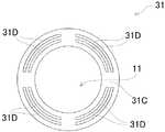
図9は、この発明における堰堤部の他の礼を示す平面図である。図9に示されるように、堰堤部31は、図8に示される堰堤部31と同様に、筒状側壁部と円盤状縁辺部とを有する。図9に示される堰堤部31が図8に示される堰堤部31と相違するところは、図9に示される堰堤部31はその円盤状縁辺部31Cに、複数の、弧状に形成された、上から下へと貫通する弧状スリット31Dを有しているに対し、図8に示される堰堤部31はその円板上縁辺部31Cに複数の円形の貫通孔31Aを有することである。言うまでもないが、この弧状スリット31Dは、この発明における溶液進入部の一例である。 FIG. 9 is a plan view showing another thanks to the dam portion in the present invention. As shown in FIG. 9, the
図9に示す堰堤部31にあっても、堰堤部31における円形開口部からその内部に酵素溶液を供給すると、酵素溶液は複数の弧状スリット31Dに毛細管現象で吸い込まれ、前記円形開口部において凸状に上方に盛り上がらずに平らになる。 Even in the
毛細管現象により堰堤部における開口部に酵素溶液を凸状に盛り上がらせないようにすることがこの発明における堰堤部についての基本的技術思想であるなら、図10に示す堰堤部31もまた、この発明の範囲内にある。 If it is a basic technical idea about the dam part in the present invention to prevent the enzyme solution from being raised in a convex shape at the opening part in the dam part due to capillary phenomenon, the
図10に示す堰堤部31は、図8に示される堰堤部31と同様に、筒状側壁部と縁庇部の一例である円盤状縁辺部とを有する。図10に示される堰堤部31が図8に示される堰堤部31と相違するところは、図10に示される堰堤部31はその円盤状縁辺部31Cに、放射状に形成された、上から下へと貫通する複数の放射状スリット31Eを有しているに対し、図8に示される堰堤部31はその円板上縁辺部31Cに複数の円形の貫通孔31Aを有することである。この放射状スリット31Eは、この発明における溶液進入部の一例である。 The
図10に示される堰堤部31は、堰堤部31における円形開口部からその内部に酵素溶液を供給すると、酵素溶液は複数の放射状スリット31Eに毛細管現象で吸い込まれ、前記円形開口部において凸状に上方に盛り上がらずに平らになる。 When the enzyme solution is supplied into the
酵素センサ用電極構造体におけるこの堰堤部を形成する材質としては、所定形状の堰堤部を形成するのが容易であり、酵素層を形成する素材及び試料液により劣化することがない限り様々の材質を選択することができる。また、この堰堤部は、成形法を選択することにより基板と一体となったものとして形成されることができ、そうすると、基板と一体になった堰堤部は基板と同じ材質例えばセラミックス、プラスチック、紙及びこれらを複合してなる複合材料で形成することができる。 As a material for forming the dam portion in the electrode structure for the enzyme sensor, various materials can be used as long as it is easy to form the dam portion of a predetermined shape and the material does not deteriorate due to the material forming the enzyme layer and the sample solution. Can be selected. In addition, the dam portion can be formed as an integral part of the substrate by selecting a molding method, so that the dam portion integral with the substrate is made of the same material as the substrate, for example, ceramic, plastic, paper And it can form with the composite material which combines these.
このような堰堤部31で取り囲まれた領域に作用極11が形成される。作用極11は、前記堰堤部31で取り囲まれた領域内に形成された作用極用電極25の表面に、一層の酵素層を形成する場合には酵素を含有する酵素溶液を、また第1酵素層及び第2酵素層を積層してなる酵素層を形成する場合には酵素を含有する第1酵素溶液次いで第2酵素溶液を塗布することにより、作用極用電極25の表面に酵素層を均一な膜厚で、作用極用電極の表面からはみ出すことなく、形成することができる。このように、作用極用電極の表面に、作用極用電極からはみ出すことなく、均一な厚みで酵素層が形成されて成る作用極を有する酵素センサ用電極構造体を備えた酵素センサにおいては、グルコースを含有する測定液が第2酵素層から第1酵素層を介して作用極用電極に到達するまでの所要時間が一定となるので好ましい。換言すると、この発明の酵素センサ用電極構造体を多数製造したときに、いずれの酵素層も平坦であるので、酵素センサの測定のばらつきを低減することができるのである。 The working
この発明に係る酵素センサ用電極構造体においては対極は必ずしも必要ではないが、この発明の一例である酵素センサに組み込まれた酵素センサ用電極構造体においては、対極が設けられる。図3及び図4に示されるように、対極13は、基板14の表面に形成された配線パターン24Cの表面に形成された対極用電極29として形成される。換言すると、この例においては、対極用電極29そのものが対極13である。この対極13は、円盤型に形成された前記作用極11を、堰堤部31を介して囲繞するように、形成される。また、堰堤部31が形成されていると、前記作用極用電極25の上表面に第1酵素層26を形成するに際し、第1酵素層26を形成するための第1酵素層形成液が隣接する対極13の表面に溢流乃至流延することが防止される。 In the electrode structure for an enzyme sensor according to the present invention, a counter electrode is not necessarily required, but in the electrode structure for an enzyme sensor incorporated in an enzyme sensor which is an example of the present invention, a counter electrode is provided. As shown in FIGS. 3 and 4, the
図3に示される酵素センサ用電極構造体においては、この対極13の平面形状は、略長方形をなし、その長手辺から中央部に向かって、配線パターン24Aを引き出すとともに、前記堰堤部31を形成するに必要な切り欠き部を形成してなるが、この発明に係る酵素センサ用電極構造体における対極の平面形状は、検量範囲が縮小しない限り、すなわち測定可能なグルコースの量が低下しない限り、特に制限がない。 In the electrode structure for an enzyme sensor shown in FIG. 3, the planar shape of the
対極13は配線パターン24Cに電気的に接続される。配線パターン24Cは、配線パターン24Aと同様の材料で形成されることができ、低抵抗材料を採用することができ、例えば、銀等を挙げることができる。この配線パターン24Cはコネクタ電極23Cに電気的に連絡している。 The
図3及び図4に示されるように、参照極12は、基板14の表面に形成された配線パターン24Bに電気的に接続される。配線パターン24Bは、配線パターン24Aと同様の材料で形成されることができ、例えば低抵抗材料を採用することができ、例えば、銀等を挙げることができる。この配線パターン24Bはコネクタ電極23Bに電気的に連絡している。 As shown in FIGS. 3 and 4, the
この発明における好適な人工膵臓用センサすなわち人工膵臓用センサ1においては、前記第2酵素層27の表面上に保護層30が形成されている。この保護層30は膜状に形成される。この保護層30は、前記作用極11、参照極12及び対極13等を保護すると共に、測定される生体物質等を前記作用極11に透過させるフィルターとしての機能を有する。保護層30は、このように機能する膜であれば特に限定されず、例えば、前記水不溶性の高分子材料で形成された膜であってもよく、また、ポリカーボネート、ポリビニルアルコール、セルローズアセテート等の高分子材料によって形成された膜に所望の径を持つ孔が形成された膜であってもよい。このような膜材料を、例えばPVA等の貼り合わせ剤を介して電極面に被着することで前記保護層30を形成する。 In the preferred artificial pancreas sensor according to the present invention, that is, the
図示しないが、この人工膵臓用センサ1には、温度検出手段及びヒータ部材を設けるようにしてもよい。温度検出手段は、基板14上の参照極12や対極13と干渉しない領域に形成し、セル16内に流通する試料液等の温度を検出させる。温度検出手段として適用可能なものとしては、例えば、熱電対、抵抗温度計、サーミスタ等である。その大きさや厚さ等は特に限定されず、形状としては、例えば、ビード型、ディスク型、ロッド型、薄膜型、チップ型等に形成することができる。また、ヒータ部材は、基板14の裏面側、又は筐体10を取り付けたときにその基板14の裏面が接する基台2の床面上に設ける。このヒータ部材は、前記温度検出手段によって感知した温度に基づいて、基板14を介して、セル16内の試料液等を加熱し、試料液等の温度を所望の温度に保つ。例えば、前記酵素としてβ−D−グルコースオキシダーゼを選択した場合には、その温度はヒータ部材によって約37℃に保たれる。ヒータ部材の大きさ、形状等は特に限定されないが、その厚さは、例えば、5〜100μmに調整される。ヒータ部材を形成する材料は、通電等によって発熱する材料であればよく、例えば、導電性金属酸化物、炭素材料が挙げられる。これらの中でも炭素材料が好ましい。 Although not shown, the
この発明に係る人工膵臓用センサ1は、そのセル16を形成する内部表面に、前記作用極11、参照極12、及び対極13を、これらが測定対象分子を含有するサンプルに接触可能に、一体に積層形成してなる。この人工膵臓用センサ1を基台2に装着すると、前記作用極11、参照極12、及び対極13から延在する配線パターン24A,24B,24Cに連絡する電気的コネクタ23A,23B,23Cが電気的コネクタ7に接続され、この電気的コネクタ7が例えばポテンショスタット(図示せず。)に接続されることにより測定対象分子の濃度等を測定可能である。 The
この発明に係る人工膵臓用センサ1の作用および効果を以下に説明する。 The operation and effect of the
図5に示されるように、この人工膵臓用センサ1における突出板部22を基台2とコネクタ部8との間隙に向けてこの人工膵臓用センサ1を斜めに差し込む。突出板部22を基台2とコネクタ部8との間隙にしっかりと挿入されると、6に示されるように、この人工膵臓用センサ1の垂直端面部17側を下方に押し下げて、この垂直端面部17と垂直面部2Aとが面接触させる。そうすると、導出開口部4と液導入口18とが、また導入開口部6と液導出口19とがそれぞれ液密に結合する。また、前記突出板部22を基台2とコネクタ部8との間隙に挿入することにより、コネクタ電極7と電気的コネクタ23A,23B,23Cとが電気的に接続される。 As shown in FIG. 5, the
次いで、測定対象分子として、例えば、グルコースを測定する場合には、グルコースを含有する試料液がセル16内に導入される。セル16内では、保護層30における、測定対象分子が通過可能な孔をグルコースが速やかに透過する。透過したグルコースは、第2酵素層27中の酵素と接触することにより、過酸化水素が発生する。この過酸化水素は、第1酵素層26において、ペルオキシダーゼにより還元されて水になるとともにペルオキシダーゼ自体が酸化ペルオキシダーゼになる。この酸化ペルオキシダーゼは金属錯体含有ポリマー例えばオスミウムポリマ中のオスミウムを二価から三価に酸化する。三価のオスミウムは、作用極用電極25中に通電されている電流から電子を受け取って還元されて二価になる。こうして作用極用電極25中の電流の変化又は還元電流の発生を検出することにより、測定対象分子の濃度が測定されることになる。 Next, as a measurement target molecule, for example, when measuring glucose, a sample solution containing glucose is introduced into the
作用極用電極25における電流変化とグルコースの基質濃度とは、例えば比例関係のような相関関係が認められている。したがって、この人工膵臓用センサにて電流変化を測定することにより、測定対象分子例えばグルコース濃度を定量することができる。 A correlation such as a proportional relationship is recognized between the current change in the working
なお、この発明の人工膵臓用センサは上記説明に係る人工膵臓用センサに限定されず、種々の設計変更が可能である。 The artificial pancreas sensor of the present invention is not limited to the artificial pancreas sensor according to the above description, and various design changes can be made.
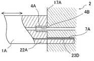
例えば、図7に示されるように、人工膵臓用センサにおける液導入口と、液導出口と、基板における電気的コネクタに電気的に接続されるところの、導電層に連絡する電気的コネクタとは、人工膵臓用センサの外殻である筐体の一面例えば一側面に形成されていても良い。 For example, as shown in FIG. 7, the liquid connector in the sensor for artificial pancreas, the liquid outlet, and the electrical connector that is electrically connected to the electrical connector on the substrate are connected to the conductive layer. Further, it may be formed on one surface, for example, one side surface, of the casing which is the outer shell of the artificial pancreas sensor.
図7に示すように、人工膵臓用センサ1Aの一端に突出板部22Aが突出形成され、その突出板部22Aの一面つまり上面に電気的コネクタ23Dが形成され、前記突出板部22Aの基部に垂直に立ち上がる垂直先端面部17Aが形成され、この垂直先端面部17Aに液導入口4A及び液導出口(図示せず。)が開設される。 As shown in FIG. 7, a protruding
一方、基台2は、その一側面に、前記液導入口4Aに挿入可能に突出して形成された導出開口部4Bを備えるとともに、前記液導出口に挿入可能に突出して形成された導入開口部(図示せず)を備え、前記電気的コネクタ23Dに電気的に結合可能な電気的コネクタ7Aを内表面に有し、かつ前記突出板部22Aを挿入可能なコネクタ挿入口7Bを備える。 On the other hand, the
このような基台2及び人工膵臓用センサ1Aの構造であると、人工膵臓用センサ1Aの突出板部22Aをコネクタ挿入口7Bに挿入するワンタッチ操作で基台2に人工膵臓用センサ1Aを装着することができる。 With such a structure of the
この発明によると、金属錯体含有ポリマー及びペルオキシダーゼを有する第1酵素層及び酵素層を含有するので、検出電位を−200〜0mV程度の低い電位に設定することができる。このような低い電位においては、グルコース等に含まれる不純物は、酸化されない。 According to this invention, since the first enzyme layer and the enzyme layer having the metal complex-containing polymer and peroxidase are contained, the detection potential can be set to a low potential of about −200 to 0 mV. At such a low potential, impurities contained in glucose and the like are not oxidized.
上述した人工膵臓用センサを人工膵臓装置に組み込むことにより、この発明の人工膵臓装置を得ることができる。この発明に係る人工膵臓装置は、この発明の酵素センサ、特にこの発明の酵素センサ用電極構造体を備えているので、人工膵臓装置内を流通するグルコース含有の液体中に気泡が混入していても、酵素層部分に気泡が付着し難く、グルコースの測定を正確に行うことができる。 The artificial pancreas device of the present invention can be obtained by incorporating the above-mentioned artificial pancreas sensor into the artificial pancreas device. Since the artificial pancreas device according to the present invention includes the enzyme sensor of the present invention, particularly the electrode structure for the enzyme sensor of the present invention, air bubbles are mixed in the glucose-containing liquid flowing through the artificial pancreas device. However, it is difficult for bubbles to adhere to the enzyme layer portion, and glucose can be measured accurately.
(実施例1)
この発明の人工膵臓用センサの一例を以下のようにして形成した。基板(材質はポリエチレンテレフタレートである。)上に、作用極用、参照極用及び対極用の配線パターンを形成した。スクリーン印刷法により、作用極用配線パターン上に炭素で直径1.5mmの円形の作用極層を形成し、この作用極層を囲繞するように、円環状の堰堤部を介して、対極用配線パターン上に炭素で8.9×3.25mmの対極層を形成した。参照極用配線パターンには、銀/塩化銀で3×4.15mmの参照極をスクリーン印刷法により形成した。前記作用極層上に、オスミウムポリマーおよびペルオキシダーゼを含む溶液0.5μLを、マイクロシリンジで滴下した。滴下した部分を乾燥させ、第1酵素層を形成した。(Example 1)
An example of the artificial pancreas sensor of the present invention was formed as follows. On the substrate (material is polyethylene terephthalate), wiring patterns for the working electrode, the reference electrode, and the counter electrode were formed. A circular working electrode layer having a diameter of 1.5 mm is formed of carbon on the working electrode wiring pattern by screen printing, and the counter electrode wiring is formed via an annular dam so as to surround the working electrode layer. A counter electrode layer of 8.9 × 3.25 mm was formed of carbon on the pattern. In the reference electrode wiring pattern, a 3 × 4.15 mm reference electrode was formed by screen printing using silver / silver chloride. On the working electrode layer, 0.5 μL of a solution containing an osmium polymer and peroxidase was dropped with a microsyringe. The dropped part was dried to form a first enzyme layer.
次に、グルコースデオキシダーゼ(GOD)をポリビニルアルコールに溶かし、GOD10質量%のGOD溶液を作製した。作製したGOD溶液を前記第1酵素層上に塗布して、第2酵素層を形成した。このとき、第1酵素層上に塗布されたGOD溶液は、前記堰堤部を越えて溢流することがなかった。 Next, glucose deoxidase (GOD) was dissolved in polyvinyl alcohol to prepare a GOD solution containing 10% by mass of GOD. The prepared GOD solution was applied on the first enzyme layer to form a second enzyme layer. At this time, the GOD solution applied on the first enzyme layer did not overflow beyond the dam part.
さらに、多孔質性(孔径:0.2μm)のポリカーボネートフィルムをポリビニルアルコールによって、酵素膜上に貼り付けた。以上の製造手順で得られたところの、配線パターン上に第1酵素層、及び第2酵素層を積層して成る作用極層を有する基板と覆蓋体とを超音波溶着により一体化することにより人工膵臓用センサを形成した。この人工膵臓用センサを基台に装着して、血液中のグルコース濃度を測定した。 Furthermore, a porous polycarbonate film (pore size: 0.2 μm) was attached onto the enzyme membrane with polyvinyl alcohol. By integrating the substrate having the working electrode layer formed by laminating the first enzyme layer and the second enzyme layer on the wiring pattern obtained by the above manufacturing procedure and the cover body by ultrasonic welding. An artificial pancreas sensor was formed. The artificial pancreas sensor was mounted on a base and the glucose concentration in the blood was measured.
(実施例2)
前記実施例1と同様にして基板表面に、実施例1におけるのと同様の、作用極用、参照極用及び対極用の配線パターンを印刷した。前記実施例1におけるのと同様にして各配線パターン上に作用極層、参照極及び対極層を形成した。前記作用極層上に、ペルオキシダーゼとオスミウムポリマーとを含む溶液を滴下して第1酵素層としてのペルオキシダーゼ層を形成し、次いでこのペルオキシダーゼ層の上に、光架橋樹脂であるPVA−Sbq(東洋合成工業株式会社製)中にグルコースオキシダーゼ(GOD)を溶解してなるGOD溶液を、塗布することにより、第2酵素層であるグルコースオキシダーゼ層を積層形成し、これによって第1酵素層及び第2酵素層からなる二層構成の酵素層を形成した。(Example 2)
In the same manner as in Example 1, wiring patterns for the working electrode, the reference electrode, and the counter electrode were printed on the substrate surface in the same manner as in Example 1. The working electrode layer, the reference electrode and the counter electrode layer were formed on each wiring pattern in the same manner as in Example 1. A solution containing peroxidase and an osmium polymer is dropped on the working electrode layer to form a peroxidase layer as a first enzyme layer, and then, PVA-Sbq (Toyo Gosei Co., Ltd.), a photocrosslinking resin, is formed on the peroxidase layer. By applying a GOD solution obtained by dissolving glucose oxidase (GOD) in Kogyo Co., Ltd., a glucose oxidase layer, which is a second enzyme layer, is laminated to form a first enzyme layer and a second enzyme. A two-layer enzyme layer consisting of layers was formed.
さらに、多孔質性(孔径:0.2μm)のポリカーボネートフィルムを前記GOD溶液が乾燥する以前に張り合わせた。ポリビニルアルコールによって、酵素膜上に貼り付けた。以上の製造手順で得られたところの、配線パターン上に第1酵素層、第2酵素層を積層して成る作用極層を有する基板と覆蓋体とを超音波溶着により一体化することにより人工膵臓用センサを形成した。この人工膵臓用センサを基板に装着して、血液中のグルコース濃度を測定した。 Further, a porous (pore size: 0.2 μm) polycarbonate film was laminated before the GOD solution was dried. It stuck on the enzyme film | membrane with polyvinyl alcohol. The substrate obtained by the above manufacturing procedure, which has a working electrode layer formed by laminating the first enzyme layer and the second enzyme layer on the wiring pattern, and the cover body are integrated by ultrasonic welding, thereby artificially combining them. A pancreas sensor was formed. This artificial pancreas sensor was mounted on a substrate, and the glucose concentration in blood was measured.
(比較例1)
まず、炭素電極に西洋ワサビペルオキシターゼ(HRP)を含むオスミウム−ポリビニルピリジン錯体高分子(Os-gel)溶液を導入し、溶媒蒸発法により薄膜を形成した。乾燥後、酵素を牛血清アルブミンと混合し、グルタルアルデヒド(架橋剤)と混合した後Os-gel膜上に導入して、酵素膜を形成した。この電極によって、グルコース濃度を測定した。(Comparative Example 1)
First, an osmium-polyvinylpyridine complex polymer (Os-gel) solution containing horseradish peroxidase (HRP) was introduced into a carbon electrode, and a thin film was formed by a solvent evaporation method. After drying, the enzyme was mixed with bovine serum albumin, mixed with glutaraldehyde (crosslinking agent) and then introduced onto the Os-gel membrane to form an enzyme membrane. With this electrode, the glucose concentration was measured.
実施例1及び2においては、正確なグルコース濃度の測定を行うことでき、比較例1においては、気泡が酵素膜に付着しやすいので測定の正確さは低下していた。 In Examples 1 and 2, an accurate glucose concentration measurement can be performed, and in Comparative Example 1, the accuracy of the measurement has been reduced because bubbles tend to adhere to the enzyme membrane.
この発明の酵素センサ用電極構造体は、この発明の目的を達成しうる限り、上述した実施態様及び実施例に制限されず、種々の設計変更が可能である。 The electrode structure for an enzyme sensor of the present invention is not limited to the above-described embodiments and examples as long as the object of the present invention can be achieved, and various design changes are possible.
1 人工膵臓用センサ、
2 基板
2A 垂直面部
3 導出路
4 導出開口部
5 導入路
6 導入開口部
7 電気コネクタ
8 コネクタ部
10 筐体
11 作用極
12 参照極
13 対極
14 基板
15 覆蓋体
16 セル
17 垂直端面部
18 液導入口
19 液導出口
20A,20B 連通路
21 Oリング
22 突出板部
23A,23B,23C コネクタ電極
24A,24B,24C 配線パターン
25 作用極用電極
26 第1酵素層
27 酵素層
28 参照極用電極
29 対極用電極
30 保護層
31 堰堤部
31A 貫通孔
31B 筒上側壁部
31C 円盤状縁辺部
31D 弧状スリット
31E 放射状スリット1 Artificial pancreas sensor,
2
Claims (5)
Translated fromJapanese前記作用極は、前記基板上に形成された電極層と、前記電極層上に形成された酵素層と、前記電極層及び前記酵素層を囲繞する堰堤部とを備え、
前記堰堤部は、前記酵素層を形成する以前において前記酵素層の原料である酵素溶液をこの堰堤部に収容したときにその酵素溶液の表面を水平に維持しつつその酵素溶液を保持可能に形成して成り、
前記堰堤部は前記電極層に臨む縁庇部を有し、その縁庇部は、毛細管現象により酵素溶液の進入を許容する溶液浸入部を有することを特徴とする酵素センサ用電極構造体。An electrode structure for an enzyme sensor comprising a working electrode and a reference electrode on a substrate,
The working electrode includes an electrode layer formed on the substrate, an enzyme layer formed on the electrode layer, and a dam portion surrounding the electrode layer and the enzyme layer,
The dam portion is formed so as to be able to hold the enzyme solution while maintaining the surface of the enzyme solution horizontally when the enzyme solution, which is a raw material of the enzyme layer, is accommodated in the dam portion before the enzyme layer is formed.Ri formedby,
The said dam part has an edge part which faces the said electrode layer, The edge part has the solution infiltration part which accept | permits an enzyme solution by capillary action, The electrode structure for enzyme sensors characterized by the above-mentioned.
Priority Applications (1)
| Application Number | Priority Date | Filing Date | Title |
|---|---|---|---|
| JP2009156820AJP5281503B2 (en) | 2009-07-01 | 2009-07-01 | Electrode structure for enzyme sensor, enzyme sensor, and artificial pancreas device |
Applications Claiming Priority (1)
| Application Number | Priority Date | Filing Date | Title |
|---|---|---|---|
| JP2009156820AJP5281503B2 (en) | 2009-07-01 | 2009-07-01 | Electrode structure for enzyme sensor, enzyme sensor, and artificial pancreas device |
Publications (2)
| Publication Number | Publication Date |
|---|---|
| JP2011013072A JP2011013072A (en) | 2011-01-20 |
| JP5281503B2true JP5281503B2 (en) | 2013-09-04 |
Family
ID=43592132
Family Applications (1)
| Application Number | Title | Priority Date | Filing Date |
|---|---|---|---|
| JP2009156820AExpired - Fee RelatedJP5281503B2 (en) | 2009-07-01 | 2009-07-01 | Electrode structure for enzyme sensor, enzyme sensor, and artificial pancreas device |
Country Status (1)
| Country | Link |
|---|---|
| JP (1) | JP5281503B2 (en) |
Families Citing this family (10)
| Publication number | Priority date | Publication date | Assignee | Title |
|---|---|---|---|---|
| JP5830499B2 (en)* | 2013-07-09 | 2015-12-09 | 日機装株式会社 | Biological component measuring device |
| JP5828869B2 (en)* | 2013-07-09 | 2015-12-09 | 日機装株式会社 | Biological component measuring device |
| JP5828868B2 (en)* | 2013-07-09 | 2015-12-09 | 日機装株式会社 | Biological component measuring device |
| WO2017187943A1 (en)* | 2016-04-27 | 2017-11-02 | パナソニックヘルスケアホールディングス株式会社 | Sensor insertion device and biosensor |
| EP3641646A1 (en)* | 2017-06-23 | 2020-04-29 | Percusense | Analyte sensor |
| CN111289596A (en)* | 2020-03-12 | 2020-06-16 | 南京腾森分析仪器有限公司 | Three-electrode system, electrochemical sensor and preparation method thereof, electrochemical workstation and application thereof |
| JP7653546B2 (en)* | 2022-01-27 | 2025-03-28 | Phcホールディングス株式会社 | Sample measurement device, sample measurement method, and sample measurement program |
| CN114923965B (en)* | 2022-03-18 | 2023-05-23 | 杭州微策生物技术股份有限公司 | Integrated multi-index sensor and manufacturing method thereof |
| JPWO2024005025A1 (en)* | 2022-07-01 | 2024-01-04 | ||
| EP4567415A1 (en)* | 2022-08-03 | 2025-06-11 | Phc Holdings Corporation | Electrode, sensor, and method for producing sensor |
Family Cites Families (8)
| Publication number | Priority date | Publication date | Assignee | Title |
|---|---|---|---|---|
| JPS63120247A (en)* | 1986-11-10 | 1988-05-24 | Takeda Medical:Kk | Simple enzyme electrode |
| JPH0339648A (en)* | 1989-07-06 | 1991-02-20 | Nok Corp | Glucose biosensor |
| US5320725A (en)* | 1989-08-02 | 1994-06-14 | E. Heller & Company | Electrode and method for the detection of hydrogen peroxide |
| US6645359B1 (en)* | 2000-10-06 | 2003-11-11 | Roche Diagnostics Corporation | Biosensor |
| JP4197085B2 (en)* | 2000-04-25 | 2008-12-17 | パナソニック株式会社 | Biosensor |
| JP4130937B2 (en)* | 2004-03-03 | 2008-08-13 | ヤマハ株式会社 | ENZYME SENSOR AND ANALYZING DEVICE USING SAME, ENZYME SENSOR MANUFACTURING METHOD, AND AMYLASE ACTIVITY MEASURING METHOD |
| EP1813937A1 (en)* | 2006-01-25 | 2007-08-01 | Roche Diagnostics GmbH | Electrochemical biosensor analysis system |
| JP2007278981A (en)* | 2006-04-11 | 2007-10-25 | Japan Advanced Institute Of Science & Technology Hokuriku | Planar electrode and electrochemical detection sensor using the same |
- 2009
- 2009-07-01JPJP2009156820Apatent/JP5281503B2/ennot_activeExpired - Fee Related
Also Published As
| Publication number | Publication date |
|---|---|
| JP2011013072A (en) | 2011-01-20 |
Similar Documents
| Publication | Publication Date | Title |
|---|---|---|
| JP5281503B2 (en) | Electrode structure for enzyme sensor, enzyme sensor, and artificial pancreas device | |
| EP1909097B1 (en) | Biosensor and biosensor cell | |
| CA2658607C (en) | Analyte sensors and methods for making and using them | |
| FI70725B (en) | ELEKTROKEMISK MAETANORDNING FOERSEDD MED EN ENZYMELEKTROD | |
| US6776888B2 (en) | Biosensor | |
| JP3655587B2 (en) | Small biosensor for continuous analyte monitoring | |
| JP5568298B2 (en) | Method for performing an electrochemical reaction in an analyte sensor | |
| JP3826189B2 (en) | Micro-assembled sensor with aperture | |
| CN1175268C (en) | Electrochemical Analysis Components | |
| US7045054B1 (en) | Small volume biosensor for continuous analyte monitoring | |
| US5120420A (en) | Biosensor and a process for preparation thereof | |
| US8696917B2 (en) | Analyte sensor and fabrication methods | |
| JP2008521418A (en) | Diffusion and enzyme layers for enzymatic sensors | |
| CN101983333A (en) | Biosensor system, sensor tip, and method of measuring analyte concentration in blood sample | |
| JP4627912B2 (en) | Biosensor | |
| JP2009264920A (en) | Sensor and biosensor | |
| JP2004325384A (en) | Biosensor | |
| JP2007298325A (en) | Electrode tip and manufacturing method thereof | |
| CN115078508B (en) | Electrochemical biosensor and preparation method thereof | |
| WO2021172557A1 (en) | Sensor and method for manufacturing same | |
| JP7362890B2 (en) | Sensor and its manufacturing method | |
| CN104968798A (en) | Electrochemical-Based Analytical Test Strips with Soluble Acidic Material Coatings | |
| JP5350531B2 (en) | Sensor | |
| JP6557090B2 (en) | Electrode tip and electrode tip manufacturing method |
Legal Events
| Date | Code | Title | Description |
|---|---|---|---|
| RD05 | Notification of revocation of power of attorney | Free format text:JAPANESE INTERMEDIATE CODE: A7425 Effective date:20110207 | |
| A621 | Written request for application examination | Free format text:JAPANESE INTERMEDIATE CODE: A621 Effective date:20120502 | |
| A977 | Report on retrieval | Free format text:JAPANESE INTERMEDIATE CODE: A971007 Effective date:20130208 | |
| A131 | Notification of reasons for refusal | Free format text:JAPANESE INTERMEDIATE CODE: A131 Effective date:20130222 | |
| A521 | Request for written amendment filed | Free format text:JAPANESE INTERMEDIATE CODE: A523 Effective date:20130415 | |
| TRDD | Decision of grant or rejection written | ||
| A01 | Written decision to grant a patent or to grant a registration (utility model) | Free format text:JAPANESE INTERMEDIATE CODE: A01 Effective date:20130510 | |
| A61 | First payment of annual fees (during grant procedure) | Free format text:JAPANESE INTERMEDIATE CODE: A61 Effective date:20130524 | |
| R150 | Certificate of patent or registration of utility model | Free format text:JAPANESE INTERMEDIATE CODE: R150 Ref document number:5281503 Country of ref document:JP Free format text:JAPANESE INTERMEDIATE CODE: R150 | |
| R250 | Receipt of annual fees | Free format text:JAPANESE INTERMEDIATE CODE: R250 | |
| R250 | Receipt of annual fees | Free format text:JAPANESE INTERMEDIATE CODE: R250 | |
| R250 | Receipt of annual fees | Free format text:JAPANESE INTERMEDIATE CODE: R250 | |
| R250 | Receipt of annual fees | Free format text:JAPANESE INTERMEDIATE CODE: R250 | |
| R250 | Receipt of annual fees | Free format text:JAPANESE INTERMEDIATE CODE: R250 | |
| R250 | Receipt of annual fees | Free format text:JAPANESE INTERMEDIATE CODE: R250 | |
| LAPS | Cancellation because of no payment of annual fees |