JP5281377B2 - Robot equipment - Google Patents
Robot equipmentDownload PDFInfo
- Publication number
- JP5281377B2 JP5281377B2JP2008309798AJP2008309798AJP5281377B2JP 5281377 B2JP5281377 B2JP 5281377B2JP 2008309798 AJP2008309798 AJP 2008309798AJP 2008309798 AJP2008309798 AJP 2008309798AJP 5281377 B2JP5281377 B2JP 5281377B2
- Authority
- JP
- Japan
- Prior art keywords
- unit
- contact
- control
- link
- hand
- Prior art date
- Legal status (The legal status is an assumption and is not a legal conclusion. Google has not performed a legal analysis and makes no representation as to the accuracy of the status listed.)
- Active
Links
Images


Classifications
- B—PERFORMING OPERATIONS; TRANSPORTING
- B25—HAND TOOLS; PORTABLE POWER-DRIVEN TOOLS; MANIPULATORS
- B25J—MANIPULATORS; CHAMBERS PROVIDED WITH MANIPULATION DEVICES
- B25J15/00—Gripping heads and other end effectors
- B25J15/0009—Gripping heads and other end effectors comprising multi-articulated fingers, e.g. resembling a human hand
- B—PERFORMING OPERATIONS; TRANSPORTING
- B25—HAND TOOLS; PORTABLE POWER-DRIVEN TOOLS; MANIPULATORS
- B25J—MANIPULATORS; CHAMBERS PROVIDED WITH MANIPULATION DEVICES
- B25J13/00—Controls for manipulators
- B25J13/08—Controls for manipulators by means of sensing devices, e.g. viewing or touching devices
- B25J13/081—Touching devices, e.g. pressure-sensitive
- B25J13/082—Grasping-force detectors
- B—PERFORMING OPERATIONS; TRANSPORTING
- B25—HAND TOOLS; PORTABLE POWER-DRIVEN TOOLS; MANIPULATORS
- B25J—MANIPULATORS; CHAMBERS PROVIDED WITH MANIPULATION DEVICES
- B25J9/00—Programme-controlled manipulators
- B25J9/16—Programme controls
- B25J9/1612—Programme controls characterised by the hand, wrist, grip control
- Y—GENERAL TAGGING OF NEW TECHNOLOGICAL DEVELOPMENTS; GENERAL TAGGING OF CROSS-SECTIONAL TECHNOLOGIES SPANNING OVER SEVERAL SECTIONS OF THE IPC; TECHNICAL SUBJECTS COVERED BY FORMER USPC CROSS-REFERENCE ART COLLECTIONS [XRACs] AND DIGESTS
- Y10—TECHNICAL SUBJECTS COVERED BY FORMER USPC
- Y10T—TECHNICAL SUBJECTS COVERED BY FORMER US CLASSIFICATION
- Y10T74/00—Machine element or mechanism
- Y10T74/20—Control lever and linkage systems
- Y10T74/20207—Multiple controlling elements for single controlled element
- Y10T74/20305—Robotic arm
- Y10T74/20329—Joint between elements
Landscapes
- Engineering & Computer Science (AREA)
- Robotics (AREA)
- Mechanical Engineering (AREA)
- Human Computer Interaction (AREA)
- Health & Medical Sciences (AREA)
- General Health & Medical Sciences (AREA)
- Orthopedic Medicine & Surgery (AREA)
- Manipulator (AREA)
Abstract
Description
Translated fromJapanese本発明は、ロボット装置に関し、特には、アーム部とハンド部とを備えたロボット装置に関する。 The present invention relates to a robot apparatus, and more particularly, to a robot apparatus including an arm unit and a hand unit.
従来、アーム部とハンド部とを備えたロボット装置が提案され、工業分野のみならず、医療福祉、農業、安全システム等の様々な分野への応用が期待されている。特に、医療福祉の分野においては、少子高齢化に伴う労働人口の減少と要介護者の増加が見込まれるため、人と同じ環境で実作業支援を行なう人間共存型のロボット装置への期待が高まっている。 Conventionally, a robot apparatus including an arm part and a hand part has been proposed, and is expected to be applied not only in the industrial field but also in various fields such as medical welfare, agriculture, and safety systems. In particular, in the field of medical welfare, a decrease in the working population and an increase in the number of care recipients due to the declining birthrate and aging population are expected, so there is an increasing expectation for humanoid robot devices that support actual work in the same environment as people. ing.
例えば、非特許文献1では、ロボットアーム先端に取り付けられた多数の指を備えた多指ハンドの指先部に圧力センサを設置したロボット装置が提案されている。この非特許文献1のロボット装置は、ハンドの指先部が人間の前腕部に触れている状態で、アームを前腕に沿って動かすと同時に、指先の圧力センサにより検出した押付力が目標値と一致するように指関節を制御することで、人の前腕部に対する清拭作業を行なうロボット装置が提案されている。
しかしながら、上記技術では、人間の前腕部等の作業対象物に指先部だけで接触しており、接触面積が小さく作業効率が悪いという欠点がある。すなわち、上記技術では、ハンド部のベース部(掌部)も接触させたハンド部全面での倣い作業を行なっていない。ところが、ハンド部全面を作業対象物に接触させた場合には、多点接触での力学モデルが複雑になるという問題がある。掌部による押付力の調節はアームの力制御により行なわれるが、ハンド部とアーム部とが発生する力は影響し合うため、アームの力制御で発生させた押付力と、実際にハンド部の接触領域全面で発生させている押付力との関係は一定とならず、アーム部とハンド部とを協調させた力制御が必要となる。しかし、多点接触の複雑な力学モデルを解析した上で、アーム部とハンド部とが協調したハンド部全面での面倣い作業をさせる力制御を行なうことは困難である。 However, the above technique has a drawback that the work object such as the human forearm is in contact with the fingertip only, and the contact area is small and the work efficiency is poor. That is, in the above technique, the copying operation is not performed on the entire surface of the hand unit with which the base unit (palm unit) of the hand unit is also in contact. However, when the entire surface of the hand unit is brought into contact with the work object, there is a problem that a dynamic model with multipoint contact becomes complicated. The adjustment of the pressing force by the palm part is performed by the arm force control, but the forces generated by the hand part and the arm part influence each other, so the pressing force generated by the arm force control and the actual force of the hand part The relationship with the pressing force generated over the entire contact area is not constant, and force control in which the arm portion and the hand portion are coordinated is required. However, it is difficult to perform a force control that performs a surface copying operation on the entire surface of the hand unit in which the arm unit and the hand unit cooperate after analyzing a complicated dynamic model of multipoint contact.
本発明は、このような実情に鑑みなされたものであり、その目的は、アーム部とハンド部とを備えたロボット装置において、面倣い作業等のハンド部での多点接触による動作を可能とし、ハンド部での多点接触による押付力の力制御をより容易に行なうことが可能なロボット装置を提供することにある。 The present invention has been made in view of such a situation, and an object of the present invention is to enable an operation by multi-point contact in a hand part such as a surface copying operation in a robot apparatus including an arm part and a hand part. Another object of the present invention is to provide a robot apparatus that can more easily perform the force control of the pressing force by multipoint contact at the hand portion.
本発明は、第1リンク部と、第1リンク部に対して相対運動する第2リンク部と、第1リンク部の接触領域における接触荷重を検出する第1接触荷重検出部と、第2リンク部の接触領域における接触荷重を検出する第2接触荷重検出部と、第1リンク部の制御目標を設定する第1リンク部制御目標設定部とを備え、第1リンク部制御目標設定部は、第1接触荷重検出部の接触荷重の検出値と、第2接触荷重検出部の接触荷重の検出値との差分を低減させるように、第1リンク部の制御目標を設定するロボット装置である。 The present invention includes a first link portion, a second link portion that moves relative to the first link portion, a first contact load detection portion that detects a contact load in a contact region of the first link portion, and a second link. A second contact load detection unit that detects a contact load in a contact region of the unit, and a first link unit control target setting unit that sets a control target of the first link unit, and the first link unit control target setting unit includes: The robot apparatus sets a control target of the first link unit so as to reduce a difference between a contact load detection value of the first contact load detection unit and a contact load detection value of the second contact load detection unit.
この構成によれば、第1リンク部と、第1リンク部に対して相対運動する第2リンク部と、第1リンク部の接触領域における接触荷重を検出する第1接触荷重検出部と、第2リンク部の接触領域における接触荷重を検出する第2接触荷重検出部と、第1リンク部の制御目標を設定する第1リンク部制御目標設定部とを備えるロボット装置において、第1リンク部制御目標設定部は、第1接触荷重検出部の接触荷重の検出値と、第2接触荷重検出部の接触荷重の検出値との差分を低減させるように、第1リンク部の制御目標を設定するため、第1リンク部と第2リンク部との接触荷重の差分が低減されることになり、第1リンク部と第2リンク部とで面倣い作業等の多点接触による動作を可能とし、多点接触による押付力の力制御をより容易に行なうことが可能となる。 According to this configuration, the first link portion, the second link portion that moves relative to the first link portion, the first contact load detection portion that detects the contact load in the contact region of the first link portion, In a robot apparatus including a second contact load detection unit that detects a contact load in a contact region of two link units, and a first link unit control target setting unit that sets a control target of the first link unit, the first link unit control The target setting unit sets the control target of the first link unit so as to reduce the difference between the contact load detection value of the first contact load detection unit and the contact load detection value of the second contact load detection unit. Therefore, the difference in the contact load between the first link part and the second link part will be reduced, and the first link part and the second link part can be operated by multipoint contact such as surface copying work, Easier force control of pressing force by multi-point contact Nau it becomes possible.
また、本発明は、第1リンク部と、第1リンク部に対して相対運動する第2リンク部と、第1リンク部に対する第2リンク部の位置及び姿勢の少なくともいずれかを検出する運動検出部と、第1リンク部の接触領域における接触荷重を検出する第1接触荷重検出部と、第2リンク部の接触領域における接触荷重を検出する第2接触荷重検出部と、第1リンク部の制御目標を設定する第1リンク部制御目標設定部とを備え、第1リンク部制御目標設定部は、第1接触荷重検出部の接触荷重の検出値と、第2接触荷重検出部の接触荷重の検出値と、運動検出部が検出した第1リンク部に対する第2リンク部の位置及び姿勢の少なくともいずれかとに基づいて、第1リンク部の制御目標を設定するロボット装置である。 Further, the present invention provides a motion detection that detects at least one of the first link portion, the second link portion that moves relative to the first link portion, and the position and posture of the second link portion relative to the first link portion. A first contact load detection unit that detects a contact load in the contact region of the first link unit, a second contact load detection unit that detects a contact load in the contact region of the second link unit, and a first link unit A first link unit control target setting unit configured to set a control target, wherein the first link unit control target setting unit includes a contact load detection value of the first contact load detection unit and a contact load of the second contact load detection unit. And a control target for the first link unit based on at least one of the position and orientation of the second link unit relative to the first link unit detected by the motion detection unit.
この構成によれば、第1リンク部と、第1リンク部に対して相対運動する第2リンク部と、第1リンク部に対する第2リンク部の位置及び姿勢の少なくともいずれかを検出する運動検出部と、第1リンク部の接触領域における接触荷重を検出する第1接触荷重検出部と、第2リンク部の接触領域における接触荷重を検出する第2接触荷重検出部と、第1リンク部の制御目標を設定する第1リンク部制御目標設定部とを備えたロボット装置において、第1リンク部制御目標設定部は、第1接触荷重検出部の接触荷重の検出値と、第2接触荷重検出部の接触荷重の検出値と、運動検出部が検出した第1リンク部に対する第2リンク部の位置及び姿勢の少なくともいずれかとに基づいて、第1リンク部の制御目標を設定するため、第1リンク部の制御目標の設定に、第1リンク部の接触荷重と、第2リンク部の接触荷重と、第1リンク部に対する第2リンク部の位置及び姿勢の少なくともいずれかとがフィードバックされることになり、第1リンク部と第2リンク部とで面倣い作業等の多点接触による動作を可能とし、多点接触による押付力の力制御をより容易に行なうことが可能となる。 According to this configuration, the first link unit, the second link unit that moves relative to the first link unit, and the motion detection that detects at least one of the position and orientation of the second link unit relative to the first link unit. A first contact load detection unit that detects a contact load in the contact region of the first link unit, a second contact load detection unit that detects a contact load in the contact region of the second link unit, and a first link unit In the robot apparatus including the first link unit control target setting unit that sets the control target, the first link unit control target setting unit detects the contact load detection value of the first contact load detection unit and the second contact load detection. In order to set the control target of the first link unit based on the detected value of the contact load of the unit and at least one of the position and orientation of the second link unit with respect to the first link unit detected by the motion detection unit, Link system In setting the target, the contact load of the first link part, the contact load of the second link part, and at least one of the position and orientation of the second link part with respect to the first link part are fed back, The link portion and the second link portion can be operated by multipoint contact such as surface copying, and the force control of the pressing force by multipoint contact can be performed more easily.
なお、本願において、「位置及び姿勢の少なくともいずれか」とは、例えば、位置の3自由度と、姿勢の3自由度とがあり、合計で6自由度ある場合において、これらの6自由度の組合せのすべてを含むものとする。例えば、位置(X,Y,Z)と姿勢(φ,θ,Ψ)とに対し、位置Xと姿勢θのみの2自由度の場合をはじめ、姿勢θ、φのみの2自由度の場合や、位置X,Yと姿勢θ,Ψの4自由度の場合等を全て含むものとする。 In the present application, “at least one of position and orientation” means, for example, that there are 3 degrees of freedom of position and 3 degrees of freedom of posture, and when there are 6 degrees of freedom in total, these 6 degrees of freedom Includes all combinations. For example, with respect to the position (X, Y, Z) and the posture (φ, θ, Ψ), the case of two degrees of freedom with only the posture θ and φ, as well as the case of two degrees of freedom with only the position X and the posture θ, In addition, all the cases of four degrees of freedom of the positions X and Y and the postures θ and Ψ are included.
また、本発明は、アーム部と、アーム部先端のハンド部と、アーム部の制御目標を設定するアーム制御目標設定部と、を備え、ハンド部は、アーム部先端に対して取付けられるベース部と、ベース部に対して可動の少なくとも1つのリンク部と、作業対象物の作業対象面に対するベース部の接触領域における2箇所以上の点の押付力を検出するベース押付力検出部と、作業対象物の作業対象面に対するリンク部の接触領域における点の押付力を検出するリンク押付力検出部と、リンク部のベース部に対する位置及び姿勢の少なくともいずれかを検出するリンク可動状態検出部と、を有し、アーム制御目標設定部は、ベース押付力検出部が検出したベース部の接触領域における点の押付力と、リンク押付力検出部が検出したリンク部の接触領域における点の押付力と、リンク可動状態検出部が検出したリンク部のベース部に対する位置及び姿勢の少なくともいずれかとに基づいて、アーム部の制御目標を設定する、ロボット装置である。 The present invention also includes an arm part, a hand part at the tip of the arm part, and an arm control target setting part for setting a control target of the arm part, and the hand part is a base part attached to the tip of the arm part A base pressing force detection unit that detects pressing force at two or more points in a contact area of the base unit with respect to the work target surface of the work target, and a work target. A link pressing force detection unit that detects a pressing force of a point in a contact area of the link unit with respect to a work target surface of the object, and a link movable state detection unit that detects at least one of a position and a posture of the link unit with respect to the base unit. The arm control target setting unit includes a point pressing force in the contact region of the base portion detected by the base pressing force detection unit, and a contact region of the link portion detected by the link pressing force detection unit. A definitive point pressing force, based on at least one of the position and orientation relative to the base portion of the link portion linking the movable state detecting unit detects, sets the control target of the arm, a robotic device.
この構成によれば、アーム部と、アーム部先端のハンド部と、アーム部の制御目標を設定するアーム制御目標設定部とを備えたロボット装置において、ハンド部は、アーム部先端に対して取付けられるベース部と、ベース部に対して可動の少なくとも1つのリンク部と、作業対象物の作業対象面に対するベース部の接触領域における2箇所以上の点の押付力を検出するベース押付力検出部と、作業対象物の作業対象面に対するリンク部の接触領域における点の押付力を検出するリンク押付力検出部と、リンク部のベース部に対する位置及び姿勢の少なくともいずれかを検出するリンク可動状態検出部とを有するため、ベース部の接触領域における2箇所以上の点の押付力、リンク部の接触領域における点の押付力並びにリンク部のベース部に対する位置及び姿勢の少なくともいずれかといったハンド部における各種の情報を検出することができる。さらに、アーム制御目標設定部は、ベース押付力検出部が検出したベース部の接触領域における点の押付力と、リンク押付力検出部が検出したリンク部の接触領域における点の押付力と、リンク可動状態検出部が検出したリンク部のベース部に対する位置及び姿勢の少なくともいずれかとに基づいて、アーム部の制御目標を設定するため、ハンド部における各種の情報をフィードバックしてアーム部の制御が行なわれることになり、面倣い作業等のハンド部での多点接触による動作を可能とし、ハンド部での多点接触による押付力の力制御をより容易に行なうことが可能となる。 According to this configuration, in the robot apparatus including the arm unit, the hand unit at the tip of the arm unit, and the arm control target setting unit for setting the control target of the arm unit, the hand unit is attached to the tip of the arm unit. A base pressing force detecting unit that detects pressing forces at two or more points in a contact area of the base unit with respect to the work target surface of the work target; A link pressing force detection unit that detects a pressing force of a point in a contact area of the link unit with respect to a work target surface of the work target, and a link movable state detection unit that detects at least one of a position and a posture of the link unit with respect to the base unit Therefore, the pressing force of two or more points in the contact area of the base part, the pressing force of points in the contact area of the link part, and the base part of the link part Various kinds of information in the hand unit such at least one of the position and orientation to be able to detect. Further, the arm control target setting unit includes a point pressing force in the contact area of the base portion detected by the base pressing force detection unit, a point pressing force in the contact region of the link portion detected by the link pressing force detection unit, and a link Based on at least one of the position and orientation of the link portion detected by the movable state detection portion with respect to the base portion, the arm portion is controlled by feeding back various information in the hand portion to set the control target of the arm portion. Accordingly, it is possible to perform an operation by multi-point contact in the hand part such as surface copying work, and it is possible to more easily control the pressing force by multi-point contact in the hand part.
この場合、アーム制御目標設定部は、ベース部の接触領域、リンク部の接触領域、及びベース部とリンク部とを合わせた全接触領域の少なくともいずれかにおける接触圧の分布状態が目標の状態に近づくようにアーム部の制御目標を設定することが好適である。 In this case, the arm control target setting unit sets the contact pressure distribution state in at least one of the contact region of the base unit, the contact region of the link unit, and the total contact region including the base unit and the link unit to the target state. It is preferable to set the control target of the arm portion so as to approach.
この構成によれば、アーム制御目標設定部は、ベース部の接触領域、リンク部の接触領域、及びベース部とリンク部とを合わせた全接触領域の少なくともいずれかにおける接触圧の分布状態が目標の状態に近づくようにアーム部の制御目標を設定するため、ベース部の接触領域、リンク部の接触領域、及びベース部とリンク部とを合わせた全接触領域の少なくともいずれかにおいて、より作業対象物の形状に合ったアーム部の制御が可能となる。 According to this configuration, the arm control target setting unit targets the distribution state of the contact pressure in at least one of the contact area of the base part, the contact area of the link part, and the total contact area including the base part and the link part. In order to set the control target of the arm part so as to approach the state of the above, it is more work target in at least one of the contact area of the base part, the contact area of the link part, and the total contact area including the base part and the link part. It is possible to control the arm portion according to the shape of the object.
この場合、アーム制御目標設定部は、ベース部の接触領域、リンク部の接触領域、及びベース部とリンク部とを合わせた全接触領域の少なくともいずれかにおける接触圧の圧力重心が、ベース部の接触領域、リンク部の接触領域、及びベース部とリンク部とを合わせた全接触領域の少なくともいずれかにおける幾何学的重心に近づくようにアーム部の制御目標を設定することが好適である。 In this case, the arm control target setting unit is configured such that the pressure center of gravity of the contact pressure in at least one of the contact region of the base unit, the contact region of the link unit, and the total contact region including the base unit and the link unit is It is preferable to set the control target of the arm unit so as to approach the geometric gravity center in at least one of the contact region, the contact region of the link unit, and the total contact region including the base unit and the link unit.
この構成によれば、アーム制御目標設定部は、ベース部の接触領域、リンク部の接触領域、及びベース部とリンク部とを合わせた全接触領域の少なくともいずれかにおける接触圧の圧力重心が、ベース部の接触領域、リンク部の接触領域、及びベース部とリンク部とを合わせた全接触領域の少なくともいずれかそれぞれにおける幾何学的重心に近づくようにアーム部の制御目標を設定するため、例えば、ベース部の接触領域における接触圧の圧力重心が、ベース部の接触領域における幾何学的重心と一致した押圧等が可能となり、ベース部の接触領域において、より作業対象物の形状に合ったアーム部の制御が可能となる。 According to this configuration, the arm control target setting unit has a pressure centroid of the contact pressure in at least one of the contact area of the base part, the contact area of the link part, and the total contact area including the base part and the link part. In order to set the control target of the arm part so as to approach the geometric center of gravity in each of at least any one of the contact area of the base part, the contact area of the link part, and the total contact area including the base part and the link part, for example, The pressure center of gravity of the contact pressure in the contact area of the base portion can be pressed to match the geometric center of gravity in the contact area of the base portion, and the arm that more closely matches the shape of the work object in the contact region of the base portion Control of the part becomes possible.
また、リンク部の制御目標を設定するリンク制御目標設定部をさらに備え、リンク制御目標設定部は、リンク押付力検出部が検出したリンク部の接触領域における点の押付力に基づいて、リンク部の接触領域における点の押付力が目標値と一致するように、リンク部のベース部に対する位置及び姿勢の少なくともいずれかを制御するようにリンク部の制御目標を設定することが好適である。 The link control target setting unit further includes a link control target setting unit configured to set a control target for the link unit, and the link control target setting unit is based on the pressing force of the point in the contact area of the link unit detected by the link pressing force detection unit. It is preferable to set the control target of the link portion so as to control at least one of the position and the posture of the link portion with respect to the base portion so that the pressing force of the point in the contact area matches the target value.
この構成によれば、リンク部の制御目標を設定するリンク制御目標設定部は、リンク押付力検出部が検出したリンク部の接触領域における点の押付力に基づいて、リンク部の接触領域における点の押付力が目標値と一致するように、リンク部のベース部に対する位置及び姿勢の少なくともいずれかを制御するようにリンク部の制御目標を設定するため、様々な形状の作業対象物に対して柔軟に適応して、リンク部の接触領域の押付力を目標値にすることが可能となる。 According to this configuration, the link control target setting unit that sets the control target of the link unit is configured to generate a point in the contact region of the link unit based on the pressing force of the point in the contact region of the link unit detected by the link pressing force detection unit. In order to set the control target of the link part so as to control at least one of the position and the posture of the link part with respect to the base part so that the pressing force of the second part matches the target value, Adapting flexibly, it becomes possible to set the pressing force of the contact area of the link portion to a target value.
さらに、アーム制御目標設定部は、アーム部の制御目標としてアーム部の姿勢及び作業対象物に対して加える力の少なくともいずれかを制御目標として設定することが好適である。 Furthermore, it is preferable that the arm control target setting unit sets, as the control target, at least one of the posture of the arm unit and the force applied to the work target as the control target of the arm unit.
この構成によれば、アーム制御目標設定部は、アーム部の制御目標としてアーム部の姿勢及び作業対象物に対して加える力のいずれかを制御目標として設定するため、アーム部の姿勢及び作業対象物に対して加える力の少なくともいずれかの制御は、ハンド部における各種の情報をフィードバックして行なわれることになり、面倣い作業等のハンド部での多点接触による動作を可能とし、ハンド部での多点接触による押付力の力制御をより容易に行なうことが可能となる。 According to this configuration, the arm control target setting unit sets, as the control target, either the posture of the arm unit or the force applied to the work object as the control target of the arm unit. The control of at least one of the forces applied to the object is performed by feeding back various information in the hand unit, enabling operation by multipoint contact in the hand unit such as surface copying work, etc. Therefore, it is possible to more easily control the pressing force by multipoint contact.
本発明のロボット装置によれば、アーム部とハンド部とを備えたロボット装置において、面倣い作業等のハンド部での多点接触による動作を可能とし、ハンド部での多点接触による押付力の力制御をより容易に行なうことが可能となる。 According to the robot apparatus of the present invention, in a robot apparatus having an arm part and a hand part, it is possible to perform an operation by multipoint contact with the hand part such as surface copying work, and a pressing force by multipoint contact with the hand part. It becomes possible to perform the force control more easily.
以下、本発明の実施の形態について添付図面を参照して説明する。 Embodiments of the present invention will be described below with reference to the accompanying drawings.
本実施形態では、本発明に係るロボット装置を、ロボット装置のマニュピレータに適用する。本実施形態のマニュピレータは医療福祉等の分野において、清拭作業等に用いられるものである。 In the present embodiment, the robot apparatus according to the present invention is applied to a manipulator of the robot apparatus. The manipulator of the present embodiment is used for wiping work or the like in the field of medical welfare or the like.
図1は、実施形態に係るマニュピレータの構成を示す側面図である。図1に示すように、本実施形態のマニュピレータ10は、アーム部20とアーム部先端のハンド部30とを備えている。アーム部20は、人間の肩、肘及び手首に相当する部分の6自由度に受動柔軟関節21がそれぞれ設けられている。受動柔軟関節21それぞれは、各々の関節の角度を検出するセンサが内蔵されており、アーム部20の姿勢を検出するようになっている。受動柔軟関節21は、内部に機械ばねを搭載している。これにより、受動柔軟関節21は、環境との接触を伴う作業においてモデル化誤差や環境認識誤差が生じたとしても,機械的受動性でそれらを吸収しながら高速かつ安定した作業遂行を行うことが可能となる。また、受動柔軟関節21は、人への追従性に優れるため、速やかな力低減が図れる等、人との接触時の安全性を高めることが可能となる。 FIG. 1 is a side view showing the configuration of the manipulator according to the embodiment. As shown in FIG. 1, the
アーム部20は、人との接触時の安全性を高めるため、表面に衝突安全被覆・接触センサ22を有する。衝突安全被覆・接触センサ22は、アーム部20表面の接触圧情報を利用した安全制御と、アーム部20表面との接触を活用しながら介助動作や重量物の運搬を行うことも可能とされている。人間の手首に相当する部分に設けられた力覚センサ23は、6軸力覚センサであり、アーム部20の作業対象物に対して加える力を検出するためのものである。 The
ハンド部30は、アーム部20先端に対して取付けられる掌部(ベース部)40と、掌部40に対して可動の指部50を有している。掌部40は、人との接触時の安全性、安定性及び追従性を高める柔軟肉41を有している。掌部40の全面には、分布型圧力センサであるタクタイルセンサ(ベース押付力検出部)42を有している。タクタイルセンサは、人等の作業対象物の作業対象面に対する掌部40の接触領域における少なくとも2箇所以上の点の押付力を検出することが可能とされている。 The
指部50は、合計4本の指を有し、人の親指に相当する指には、掌部40との付け根の関節を含め各々1自由度の2つの関節が設けられ、その他の各指には掌部40との付け根の関節を含め各々1自由度の3つの関節が設けられている。各関節には力覚センサ(リンク可動状態検出部)52が設けられ、各指の作業対象物に加える力を検出する他、指部50の掌部40に対する位置及び姿勢を検出するようになっている。また、指部50の全面には、分布型圧力センサであるタクタイルセンサ(リンク押付力検出部)53が設けられ、人等の作業対象物の作業対象面に対する指部50の各指の接触領域における点の押付力を検出することが可能とされている。 The
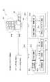
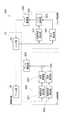
図2は、実施形態に係るマニュピレータ10の制御系を示すブロック図である。図2に示すように、マニュピレータ制御系100は、制御対象であるマニュピレータ10のアーム部20とハンド部30とに対して、アーム制御部(アーム制御目標設定部)200とハンド制御部(ハンド制御目標設定部)300とを有する。アーム部20からのアーム部20の端部位置、端部姿勢及び端部発生力に関する信号は、アーム制御部200の端部位置検出部201、端部姿勢検出部202及び端部発生力検出部203に入力される。 FIG. 2 is a block diagram illustrating a control system of the
端部位置検出部201からの検出信号は、アーム制御部200の位置制御部204によって処理され、位置制御部204はアーム部20の位置の制御目標値を算出する。端部姿勢検出部202からの検出信号は、アーム制御部200の姿勢制御部205によって処理され、姿勢制御部205はこれに基づきアーム部20の姿勢の制御目標値を算出する。また、姿勢制御部205は、ハンド制御部300の圧力検出部302から、ハンド部30の掌部40の押圧力に関する検出信号を入力され、これに基づきアーム部20の姿勢の制御目標値を算出する。 A detection signal from the end
端部発生力検出部203からの検出信号は、アーム制御部200の力制御部206によって処理され、これに基づき力制御部206はアーム部20の作業対象物に加える力の制御目標値を算出する。また、力制御部206は、ハンド制御部300の関節角度検出部301から、指部50の掌部40に対する位置及び姿勢に関する検出信号を入力され、これに基づき力制御部206はアーム部20の作業対象物に加える力の制御目標値を算出する。さらに、力制御部206は、ハンド制御部300の圧力検出部302から、ハンド部30の指部50の押圧力に関する検出信号を入力され、これに基づき力制御部206はアーム部20の作業対象物に加える力の制御目標値を算出する。 The detection signal from the end generated
アーム制御部200の位置制御部204、姿勢制御部205及び力制御部206は、各々の制御目標値をアーム駆動部250に出力し、アーム部20を制御する。 The
一方、ハンド部30からのハンド部30の指部50の各関節角度、並びに掌部40及び指部50の押付力に関する信号は、ハンド制御部300の関節角度検出部301及び圧力検出部302にそれぞれ入力される。関節角度検出部301からの指部50の各関節角度に関する検出信号と、圧力検出部302からの掌部40及び指部50の押付力に関する検出信号とは、ハンド制御部303によって処理され、これらに基づきハンド制御部303は、指部50の各関節角度並びに掌部40及び指部50の押付力の制御目標値を算出する。 On the other hand, signals related to the joint angles of the
関節角度検出部301は、上述のようにアーム制御部200の力制御部206に対して指部50の掌部40に対する位置及び姿勢に関する検出信号を出力する。また、圧力検出部302は、上述のようにアーム制御部200の力制御部206に対してハンド部30の指部50の押圧力に関する検出信号を出力する。さらに、圧力検出部302は、上述のようにアーム制御部200の姿勢制御部205に対して掌部40の押圧力に関する検出信号を出力する。 The joint
ハンド制御部303は、各々の制御目標値をハンド駆動部350に出力し、ハンド部30を制御する。 The
図3は、実施形態に係る指とアームとの協調のための制御アーキテクチャーを示すブロック図である。図3に示すように、手首力センサ401からの検出信号は圧力制御405のために利用される。手掌接触状態402における圧力偏差は姿勢制御404のために利用され、手掌接触状態402の制御にフィードバックされる。手指接触状態403における接触力は指間接コンプライアンス制御406のために利用され、手指接触状態403の制御にフィードバックされる。さらに、手指接触状態403における接触力は圧力制御405のためにも利用され、圧力制御405により手掌接触状態402の制御が行われる。 FIG. 3 is a block diagram illustrating a control architecture for cooperation between fingers and arms according to the embodiment. As shown in FIG. 3, the detection signal from the
本実施形態において、ハンド部30全体を作業対象物に接触させるためには、大きく分けて二つの部位に分けることにより簡単に考えることができる。図4は、本実施形態に係るマニュピレータの全体の制御フローを示す図である。図4に示すように、本実施形態では、ハンド部30の根元に位置する掌部40とハンド部30の先端に位置する指部50の2つに分けることとする。 In the present embodiment, in order to bring the
まず、掌部40の接触について考える。本実施形態では、アーム部20の手先関節で掌部40の接触状態を制御する。具体的には、掌部40の接触圧の偏りを無くすための(1)アーム手先姿勢制御A、及び掌部(パーム)40の押付力を一定に保つための(2)アーム手先力修正制御Bが必要となる。さらに、指部50が作業対象物に倣うための(3)手指コンプライアンス制御Cが必要となる。以上の基本的な3つの制御に加えて、アーム部20においては、清拭方向への移動を行うための制御が必要となる。 First, consider the contact of the
図4に示すように、アーム手先姿勢制御Aは、アーム520の手先位置(関節角度)521、ハンド530の接触圧情報531及び関節角度532の情報に基づいて行われ、アーム520の手先位置521にフィードバックされる。アーム手先力修正制御Bは、アーム520の手先位置521、手首力情報522、ハンド530の接触圧情報531及び関節角度532の情報に基づいて行われ、アーム520の手先位置521にフィードバックされる。アーム520の手先位置521は位置制御523に利用される。手指コンプライアンス制御Cは、ハンド530の接触圧情報531及び関節角度532の情報に基づいて行われ、ハンド530の関節角度532にフィードバックされる。以下、各部の制御について詳細を説明する。 As shown in FIG. 4, the arm hand posture control A is performed based on the hand position (joint angle) 521 of the
(1 アームコンプライアンス制御)
(1.1 アームハイブリッド制御)
本実施形態では、アーム部20の押付方向に力制御、掌部40の接触を確保するための手先姿勢制御、及び清拭方向への位置制御が必要となるため、これらをハイブリッド制御により行う。そこで、ハイブリッド制御について以下に簡単に説明する。(1 Arm compliance control)
(1.1 Arm hybrid control)
In the present embodiment, force control in the pressing direction of the
(1.1.1 位置制御)
目標とする位置に対して並進力としての引力が働くようなポテンシャル場を張り、ロボットの制御対象部位に位置制御用力ベクトルRFPosを作用させる。ただし、添え字Rは力ベクトルが基準座標系で示されていることを表している。引力の強さは目標位置Pref=[xref yref zref]Tと現在位置P=[x y z]Tとの偏差ΔPの関数として以下の式を用いる。
FPos=FPosmax(1−e−αposΔP)
ΔP=|Pref−P|={(xref−x)2+(yref−y)2+(zref−z)2}1/2 (1)(1.1.1 Position control)
A potential field in which an attractive force as a translational force is applied to a target position is applied, and a position control force vectorR FPos is applied to a control target part of the robot. However, the subscript R represents that the force vector is shown in the reference coordinate system. As the strength of the attractive force, the following expression is used as a function of the deviation ΔP between the target position Pref = [xref yref zref ]T and the current position P = [x yz]T.
FPos = FPosmax (1−e−αposΔP )
ΔP = | Pref −P | = {(xref −x)2 + (yref −y)2 + (zref −z)2 }1/2 (1)
偏差と引力との強さの関係を図5に示す。この関数を用いることで、ある程度以上離れた地点での作用力を一定値FPosmaxにすることができ、αPosを調節することで目標値近傍の引力の強さを変化させることができる。FIG. 5 shows the relationship between the deviation and the attractive force. By using this function, it is possible to make the acting force at a point more than a certain distance a constant value FPosmax, and it is possible to change the strength of the attractive force near the target value by adjusting αPos .
このようにして求まった引力を下式(2)によって目標位置に向けてロボットに作用させる。
RFPos=[FPos,x FPos,y FPos,z]T
=[{(xref−x)/ΔP}FPos{{(yref−y)/ΔP}}FPos{{(zref−z)/ΔP}}FPos] (2)The attractive force obtained in this way is applied to the robot toward the target position by the following equation (2).
R FPos = [FPos, x FPos, y FPos, z ]T
= [{(Xref −x) / ΔP} FPos {{(yref −y) / ΔP}} FPos {{((zref −z) / ΔP}} FPos ] (2)
(1.1.2 姿勢制御)
目標とする姿勢に対してモーメント力としての引力が働くようなポテンシャル場を張り、ロボットの制御対象部位に姿勢制御用ベクトルRMOriを作用させる。姿勢制御用ベクトルの生成手法の詳細な説明の前に、姿勢制御において重要となる姿勢の表現法と回転行列について説明する。(1.1.2 Attitude control)
A potential field is created such that an attractive force as a moment force acts on the target posture, and the posture control vectorR MOri is applied to the control target part of the robot. Prior to detailed description of a method for generating a posture control vector, a posture representation method and a rotation matrix that are important in posture control will be described.
基準座標系をΣAとし、その原点をOA、直行する3軸をXA、YA、ZAとする。また、目標とする姿勢の座標系をΣBとし、その原点をOB、直行する3軸をXB、YB、ZBとする。また、XB、YB、ZBの方向を向く単位ベクトルをΣAで表したものをAxB、AyB、AzBと書くことにする。このときΣAから見た目標姿勢は{AxB、AyB、AzB}で表現することができる。なお、左上の添字Aはそのベクトルが座標系ΣAで表されていることを示す。以後も特に断らない限りベクトルにお左上付き添字はこの約束に従うものとする。The reference coordinate system is ΣA , the origin is OA , and the three orthogonal axes are XA , YA , and ZA. The coordinate system of the target posture is ΣB , the origin is OB , and the three orthogonal axes are XB , YB , and ZB. Further, a unit vector that faces the directions of XB , YB , and ZB is represented by ΣA and written asA xB ,A yB , andA zB. Target attitude viewed from this time sigmaA can be expressed by{A x B, A y B , A z B}. Incidentally, the upper left subscript A indicates that the vector is represented by a coordinate system sigmaA. Thereafter, unless otherwise specified, the upper left subscript in the vector shall follow this promise.
ここで、姿勢は3つのベクトル{AxB、AyB、AzB}で表現することができるが、これらを、
ARB=[AxB、AyB、AzB]
と行列の形にまとめて表したものを回転行列と呼ぶ。Here, the posture can be expressed by three vectors {A xB ,A yB ,A zB }.
A R B = [A x B , A y B, A z B]
What is collectively expressed in the form of a matrix is called a rotation matrix.
ARBは9つの変数を持つがこれらの中で独立な成分は3つであり、基準座標系ΣAから、ある固定された軸周りの回転を3回順次行なった結果としてとらえ、これら3つの回転各でΣBの姿勢を表すものとして、オイラー角やロール角・ピッチ角・ヨー角による表現が知られている。オイラー角とロール角・ピッチ角・ヨー角との違いは、3つの回転の回転軸の取り方が異なるのみである。A RB is with nine variables are among 3 independent component among these, from the reference coordinate system sigmaA, taken as 3 times successively result of performing rotation around the axis that is a fixed, these 3 Expressions using Euler angles, roll angles, pitch angles, and yaw angles are known as representing the posture of ΣB for each of the two rotations. The difference between the Euler angle and the roll angle / pitch angle / yaw angle is only in the way of taking the three rotation axes.
以下、本実施形態で用いているオイラー角について説明する。
i)まず、ΣAをZA軸まわりに角度φだけ回転させた座標系ΣA’とする。
ii)次にΣA’をYA’軸まわりに角度θだけ回転させたものを座標系ΣA”とする。
iii)最後にΣA”をZA”軸まわりに角度Ψだけ回転させたものをΣBとする。Hereinafter, the Euler angles used in this embodiment will be described.
i) First, let ΣA be a coordinate system ΣA ′ rotated by an angle φ around the ZA axis.
ii) then sigmaA 'to YA' and axis coordinate system which is rotated by an angle θ about sigmaA ".
iii) Finally, ΣB is obtained by rotating ΣA ″ by an angle Ψ around the ZA ″ axis.
このとき、ΣAからみたΣBの姿勢は3つの角度の組(φ,θ,Ψ)で表現でき、この組をオイラー角と呼ぶ。これら3つの回転の合成からなる回転行列ARBは、下式(3)に示すようになる。
At this time, the attitude of ΣB viewed from ΣA can be expressed by a set of three angles (φ, θ, Ψ), and this set is called Euler angle.A rotation matrixA RB composed of a combination of these three rotations is expressed by the following equation (3).
ロボットの姿勢を制御する際に、このオイラー角やロール角・ピッチ角・ヨー角をそのまま用いるには、3つの回転軸を順番に制御しなければ目標とする姿勢を実現することができない。よって、3つの軸周りのモーメントを同時に作用させて制御するためには、これを直接用いることができないことが判る。 In order to use the Euler angle, roll angle, pitch angle, and yaw angle as they are when controlling the posture of the robot, the target posture cannot be realized unless the three rotation axes are sequentially controlled. Therefore, it can be seen that this cannot be used directly in order to control the moments around the three axes simultaneously.
そこで、目標姿勢へ到達するためのモーメントをある一つの座標系で一度に算出する方法が必要になる。姿勢は、オイラー角、ロール角・ピッチ角・ヨー角などのように表現法がいくつか考えられるが、回転行列に関しては一意である。そして、この回転行列は単純に座標系と座標系との関係を示しているものなので、この回転行列をもとに考えることとする。 Therefore, a method for calculating the moment for reaching the target posture at once in a certain coordinate system is required. There are several ways to express the posture, such as Euler angle, roll angle, pitch angle, yaw angle, etc., but the rotation matrix is unique. Since this rotation matrix simply indicates the relationship between the coordinate system and the coordinate system, it will be considered based on this rotation matrix.
基本的にはロボットの任意の部位における姿勢を制御することができるが、ここでは、説明の便宜のため、手先姿勢ΣHが基準座標ΣRにおいてオイラー角(φ,θ,Ψ)で表現されている場合について考える。また、目標姿勢は回転行列で表現できれば、オイラー角、及びロール角・ピッチ角・ヨー角のどちらで表現されていてもかまわない。Is basically able to control the orientation in any part of the robot, where, for convenience of explanation, Euler angles in the hand posture sigmaH is the reference coordinateΣ R (φ, θ, Ψ ) is represented by Think about when you are. Further, as long as the target posture can be expressed by a rotation matrix, it may be expressed by any of Euler angles and roll angles, pitch angles, and yaw angles.
姿勢制御用力ベクトルの生成手法は以下の手順で行なう。
1)オイラー角によって基準座標系で表現された目標姿勢Φ=(φ,θ,Ψ)の回転行列を求める。
The posture control force vector is generated by the following procedure.
1) A rotation matrix of a target posture Φ = (φ, θ, Ψ) expressed in a reference coordinate system is obtained by Euler angles.
2)目標姿勢の回転変換行列を手先座標系で表現しなおす。
2) Re-express the rotation transformation matrix of the target posture in the hand coordinate system.
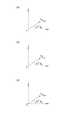
3)目標姿勢座標の各軸に対応する単位ベクトル{HXrefHYrefHZref}の手先座標系における偏差{ΔHΦx ΔHΦy ΔHΦz}を算出する。偏差{ΔHΦx ΔHΦy ΔHΦz}を算出した式を下式(6)に示す。また、手先座標系における目標姿勢座標の各軸を表したものを図6(a)〜(c)に示す。
ΔHΦx=atan2(R32,R22)
ΔHΦy=atan2(R13,R33) (6)
ΔHΦz=atan2(R21,R11)3) Calculate the unit vector corresponding to each axis of the target attitude coordinates{H X ref H Y ref H Z ref} deviation in the hand coordinate system{Δ H Φ x Δ H Φ y Δ H Φ z}. The calculated expression deviation{Δ H Φ x Δ H Φ y Δ H Φ z} shown in the following equation (6). 6A to 6C show the axes of the target posture coordinates in the hand coordinate system.
Δ H Φ x = atan2 (R 32, R 22)
Δ H Φ y = atan2 (R 13, R 33) (6)
Δ H Φ z = atan2 (R 21, R 11)
4)各軸周りの偏差に対応した目標姿勢用力ベクトルを手先座標系で算出する。この際、力ベクトルの大きさは、位置制御用力ベクトルの大きさを決めるのと同じ指数関数で求める。偏差の大きさは各軸周りの偏差のノルムを用い、各成分を決める際にもこれを用いる。
MOri=MOrimax(1−e−αOriΔΦ)
ΔΦ=(ΔHΦx2+ΔHΦy2+ΔHΦz2)1/2
RMOri=[MOri,xMOri,yMOri,z]T (7)
[(ΔHΦx/ΔΦ)MOri(ΔHΦy/ΔΦ)MOri(ΔHΦz/ΔΦ)Mori]T4) A target posture force vector corresponding to the deviation around each axis is calculated in the hand coordinate system. At this time, the magnitude of the force vector is obtained by the same exponential function that determines the magnitude of the position control force vector. As the magnitude of the deviation, the norm of the deviation around each axis is used, and this is also used when determining each component.
MOri = MOrimax (1-e−αOriΔΦ )
ΔΦ = (Δ H Φ x 2 + Δ
R MOri = [MOri, x MOri, y MOri, z ]T (7)
[(Δ H Φ x / ΔΦ ) M Ori (Δ H Φ y / ΔΦ) M Ori (Δ H Φ z / ΔΦ) M ori] T
5)手先座標系で示された目標姿勢用力ベクトルを基準座標系で表現しなおすと下式(8)のようになる。
RMOri=RRHHMOri (8)5) When the target posture force vector shown in the hand coordinate system is re-expressed in the reference coordinate system, the following equation (8) is obtained.
R MOri =R RHH MOri (8)
(1.1.3 コンプライアンス制御)
ロボットの行なう作業の中には、ドアの開閉等のように手先位置の厳密な制御のみではなく、環境との接触力を制御する必要があるものが多い。そこで、本実施形態では、位置制御・姿勢制御をベースとして構築が可能なコンプライアンス制御を用いて力制御を行なう。なお、本実施形態ではコンプライアンス制御により力制御を行なうが、制御手法はこれに限定されるものではない。(1.1.3 Compliance control)
Many of the tasks performed by the robot require not only strict control of the hand position, such as opening and closing of the door, but also control of the contact force with the environment. Therefore, in this embodiment, force control is performed using compliance control that can be constructed based on position control / attitude control. In the present embodiment, force control is performed by compliance control, but the control method is not limited to this.
力はロボットの手首部に搭載された力覚センサ23を用いて検出することを想定すると、手先力を制御するためには、ハンド部30の自重をキャンセルし、手首にかかる負荷から手先力を推定することが必要となる。 Assuming that the force is detected using the
(1.1.4 ハンドの自重キャンセル)
6軸力覚センサである力覚センサ23が手首に搭載されていた場合、センサで検出される力には常にハンド部30の自重による力も検出されており、外力を算出するには自重を差し引かなければならない。よって、力覚センサ23で検出されるハンド部30の自重を算出することとする。(1.1.4 Hand weight cancellation)
When the
手首座標における力覚センサ23の位置をWPS=[xw−s,yw−s,zw−s]、ハンド部30の重心位置をWPHg=[xw−Hg,yw−Hg,Zw−Hg]とすると、力覚センサ23とハンド部30の重心との同次変換行列は下式(9)(10)のように求まる。
The position of the
基準座標系で表したハンド分30の重心に加わる重力は、下式(8)のようになる。
RFHg・Hg=[0 0 −mHg]T,RMHg・Hg=[0 0 0]T (11)Gravity applied to the center of gravity of the
R FHg · Hg = [0 0 −mH g]T ,R MHg · Hg = [0 0 0]T (11)
これをハンド部30の重心座標系で表現すると、下式(12)のようにできる。
HgFHg,Hg=HgRR・RFHg,Hg,HgMHg,Hg=HgRR・RMHg,Hg
HgRR=(RRHg)T (12)If this is expressed in the barycentric coordinate system of the
Hg FHg, Hg =Hg RR ·R FHg, Hg ,Hg MHg, Hg =Hg RR ·R MHg, Hg
Hg RR = (R RHg )T (12)
そこで、6軸力覚センサである力覚センサ23で計測されるハンド部30の自重SFs,Hg,SMs,Hgは、下式(13)のように求まる。
Therefore, 6-axis force the
ただし、上式(13)において、記号[・×]は、任意の3次元ベクトルa=[axayaz]Tに対して、以下に示す関係を意味する。
However, in the above equation (13), symbol [· ×] is, for any three-dimensional vectora = [a x a y a z] T, means the relationship shown below.
(1.1.5 手首の力センサを用いた手先力の算出)
手首の力センサで検出した手首座標系の力をもとに、手先の負荷を基準座標系で算出する。まず、手首にかかるハンド部30の自重を算出したのと同じ要領で、手先にかかる負荷を手先座標系で下式(14)のように算出する。
(1.1.5 Calculation of hand force using wrist force sensor)
Based on the force in the wrist coordinate system detected by the wrist force sensor, the load on the hand is calculated in the reference coordinate system. First, in the same manner as the weight of the
そこで、算出した手先座標系における手先力は、下式(15)のように基準座標系で表現しなおすことができる。
RFH,ext=RRH・HFH,ext (15)
RMH,ext=RRH・HMH,extTherefore, the calculated hand force in the hand coordinate system can be re-expressed in the reference coordinate system as shown in the following equation (15).
R FH, ext =R RH ·H FH, ext (15)
R MH, ext =R RH ·H MH, ext
(1.1.6 仮想コンプライアンスに基づく並進力の制御)
仮想コンプライアンス制御を用いて並進力を制御するということは、設定した手先コンプライアンスを実現するように手先の位置を制御するということである。コンプライアンスは力による仮想バネ変位の分だけ目標手先位置をずらすことで実現されるが、ここではその仮想変位を算出する。なお、本実施形態では仮想コンプライアンス制御を用いて並進力を制御するが、制御手法はこれに限定されない。(1.1.6 Translational force control based on virtual compliance)
Controlling the translational force using virtual compliance control means controlling the position of the hand so as to realize the set hand compliance. The compliance is realized by shifting the target hand position by the amount of the virtual spring displacement due to the force. Here, the virtual displacement is calculated. In this embodiment, the translational force is controlled using virtual compliance control, but the control method is not limited to this.
目標位置、仮想バネ変位、修正された目標位置をそれぞれPref,Pcmp,Pref’とすると下式(16)が成り立つ。
Pref’=Pref+Pcmp (16)When the target position, the virtual spring displacement, and the corrected target position are Pref , Pcmp , and Pref ′, the following equation (16) is established.
Pref '= Pref + Pcmp (16)
そこで、目標手先力RFH,ref、手先力RFH、手先コンプライアンス行列CH,Pが与えられた場合、仮想バネ変位は下式(17)より求まる。
Therefore, when the target hand forceR FH, ref , the hand forceR FH , and the hand compliance matrix CH, P are given, the virtual spring displacement is obtained from the following equation (17).
(1.1.7 仮想コンプライアンス制御によるモーメント力の制御)
仮想コンプライアンス制御によって並進力を制御するということは、設定した手先コンプライアンスを実現するように手先の姿勢を制御するということである。並進力の制御の場合には、力による仮想バネ変位の分だけ目標手先位置をずらせば良かったが、モーメント力制御の場合は、常に現在の手先姿勢を基準にしなければならないため、目標姿勢との偏差を修正することで実現される。なお、本実施形態では、仮想コンプライアンス制御によって並進力を制御するが、制御手法はこれに限定されるものではない。(1.1.7 Control of moment force by virtual compliance control)
Controlling the translational force by virtual compliance control means controlling the hand posture so as to realize the set hand compliance. In the case of translational force control, it was only necessary to shift the target hand position by the amount of the virtual spring displacement due to the force, but in the case of moment force control, the current hand posture must always be used as a reference. This is realized by correcting the deviation. In the present embodiment, the translational force is controlled by virtual compliance control, but the control method is not limited to this.
目標手先モーメントRMH,ref、手先力RMH、仮想手先コンプライアンスCH,Φが基準座標系で与えられた場合、基準座標系における仮想バネ変位RΦcmpは下式(18)により求まる。
When the target hand momentRMH, ref , hand forceRMH , and virtual hand compliance CH, Φ are given in the reference coordinate system, the virtual spring displacementR Φcmp in the reference coordinate system is obtained by the following equation (18). .
これを手先座標系に変換して目標姿勢との偏差に加えて姿勢制御を行なうことで、モーメント力制御が可能となる。目標姿勢との偏差、仮想バネ変位、修正された偏差をそれぞれΔHΦ、HΦcmp、ΔHΦ’とすると、下式(19)が成り立つ。
ΔHΦ’=ΔHΦ+HΦcmp
HΦcmp=(RRH)TRΦcmp (19)By converting this to the hand coordinate system and performing posture control in addition to the deviation from the target posture, moment force control is possible. The deviation between the target posture, virtual spring displacement, delta each modified deviationH Φ, H Φcmp, when the deltaH [Phi ', the following equation (19) holds.
ΔH Φ '= ΔH Φ +H Φcmp
H Φ cmp = (R R H ) TR Φ cmp (19)
(1.2 アーム手先姿勢修正)
本実施形態では、図7(a)(c)のように掌部40のみや指部50のみで作業対象物Oに接触するのではなく、図7(b)のように掌部40及び指部50全面を均等に作業対象物Oに接触させるためにアーム手先姿勢修正を行なう。まず、姿勢修正に用いる情報について考察を行なう。(1.2 Arm hand posture correction)
In the present embodiment, the
図8(a)に示す従来の倣い動作のように接触モデルを1点接触として扱い、手首の力覚センサを用いて制御する場合は、接触モデルは単純であり、手首力覚情報から接触状態は一意に求める事ができる。これに対して、多指ハンドを用いた倣い動作のように多点接触が起きる場合を考えると、図8(b)に示すように、作業対象物Oの形状によっては、手指姿態が動的に変化したり、指列が大きく屈曲して作業対象物Oに回り込むような状況においてハンド部30の中に対向する内力が発生する。 When the contact model is handled as a one-point contact as in the conventional copying operation shown in FIG. 8A and is controlled using a wrist force sensor, the contact model is simple and the contact state is determined from the wrist force information. Can be uniquely determined. On the other hand, considering the case where multi-point contact occurs like a copying operation using a multi-fingered hand, depending on the shape of the work object O, as shown in FIG. Or an internal force that is opposed to the inside of the
これによって力学モデルは格段に複雑化し、手首力情報だけでは接触状態は一意に求めることができない。例えば、図8(b)のような状況において、掌部40の一部が作業対象物Oに接触していないにも関わらず、対向する内力が発生していることによって、手首力覚センサではモーメントが釣り合うということが起きる。 As a result, the dynamic model becomes much more complicated, and the contact state cannot be uniquely determined only by wrist force information. For example, in the situation as shown in FIG. 8B, the wrist force sensor detects that the opposing internal force is generated even though part of the
そこで、本実施形態では、従来のような手首力覚情報ではなく、掌部圧力分布情報を用いてアーム手先姿勢修正を行なう。 Therefore, in this embodiment, arm hand posture is corrected using palm pressure distribution information instead of conventional wrist force sense information.
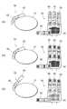
本実施形態における姿勢修正を行なう上での基本的な考え方は、掌部40の接触圧重心PCGと掌部40の幾何学重心GCGとが一致するように姿勢修正モーメントを求める。姿勢修正モーメントを求める手順としては、掌部40に配置される圧力分布センサであるタクタイルセンサ42を、図9(a)のように幾何学重心GCGを中心に4分割し、各部の圧力をそれぞれP1,P2,P3,P4とおく。続いて下式(20)のように掌部40の上下・左右にかかる圧力の偏差から修正モーメントMx,Myを算出した。なお、下式(20)においてKx,Kyはそれぞれ任意の定数である。
Mx=Kx{(P1+P2)−(P3+P4)}
My=Ky{(P1+P3)−(P2+P4)} (20)The basic idea in terms of the posture correction in the present embodiment obtains the posture correcting moment as the geometric center of gravity GCG contact圧重center PCG and the
Mx = Kx {(P1 + P2)-(P3 + P4)}
My = Ky {(P1 + P3)-(P2 + P4)} (20)
本実施形態では、このようにして求めた修正モーメントに基づき、図9(b)に示すように、アーム姿勢コンプライアンス制御にて釣り合い状態へ遷移、掌部40全面を接触させることとした。なお、本実施形態においては、掌部40の接触圧重心PCGと掌部40の幾何学重心GCGとが一致するように姿勢修正モーメントを求める他、掌部40の一部分を作業対象物Oに特に強く押し付ける等の制御目標の設定も可能である。あるいは、上記制御手法は、指部50の圧力分布情報を用いてアーム手先姿勢修正を行なうようにしても良い。さらには、掌部40及び指部50の接触領域を合わせた全接触領域を考え、当該全接触領域の圧力偏在を低減させるようにしても良く、この場合、掌部40及び指部50の接触領域を合わせた全接触領域の接触圧重心と幾何学的重心とが近づき、一致するように制御しても良い。In the present embodiment, based on the correction moment thus obtained, as shown in FIG. 9 (b), the arm posture compliance control is used to shift to the balanced state and bring the
(1.3 アーム手先力修正)
指姿勢に寄らずハンド部30での押付力を一定に保つために、アーム手先力修正を行なった。従来の倣い動作では、エンドエフェクタの形状は変化しないので手先力は一定であった。しかし、多指ハンドを用いた倣い動作では、対象形状により指姿勢が変化するため、それに伴い手先力も変化しなければならない。図10(a)(b)に示すように、手先力Fz、掌部荷重Fp、各指先力をFti(i=1〜4)、各指先姿勢θi(i=1〜4)とおく。αは掌部40と指部50との面積の比から求まる定数である。(1.3 Arm hand force correction)
In order to keep the pressing force at the
下式(21)のようにFzは求まり、図11に示すように、指先角度が大きくなるに伴い図10(b)に示す指先力のFz方向成分が小さくなるのでFzも小さくなり、指先角度が90degの時点でFzとFpが釣り合うことになる。これにより、指先姿勢に寄らずハンド部30全体での押付力を一定とすることができる。なお、本実施形態では、ハンド部30全体での押付力は一定に制御するのみならず、所定の目標値と一致させるように制御することも可能である。
Fz=Fp+ΣFti×cosθi
=αΣFti+ΣFti×cosθi (21)As shown in FIG. 11, Fz is obtained as shown in the following equation (21). As shown in FIG. 11, as the fingertip angle increases, the Fz direction component of the fingertip force shown in FIG. When F is 90 degrees, Fz and Fp are balanced. Thereby, the pressing force in the
Fz = Fp + ΣFti × cos θi
= ΑΣFti + ΣFti × cosθi (21)
(2 手指コンプライアンス制御)
(2.1 手指コンプライアンス制御の必要性)
安全性・作業性の高い清拭作業を行なうにはハンド部30全面が偏りなく作業対象物Oに接触していることが重要である。そして、掌部40の接触については、上述のアーム手先姿勢・力修正制御によって行なう。続いて指部50の接触についてはハンド指部関節のコンプライアンス制御にて行なう。なお、本実施形態では手指コンプライアンス制御を採用するが、制御手法はこれに限定されない。(2 Finger compliance control)
(2.1 Necessity of finger compliance control)
In order to perform a wiping operation with high safety and workability, it is important that the
本実施形態の多指ロボットハンドの掌部40は平面であり、その機構的制約から、小さな曲率を有する対象に全面で倣うことは難しい。しかし、図12に示すように、指部50は比較的に小さな構造部品から構成されており、また、冗長性を有しているために、図13(a)(b)に示すように小さな凹凸にたいしてもきめ細かに倣うことが可能と考えられる。さらに、指部50の関節に受動柔軟関節を搭載し、掌部40全面に柔軟被覆を搭載するなど構造的柔軟性を有しているため、特別な制御無しでも高応答に倣う事が可能である。このように本実施形態のハンド部30は倣い動作をさせるのに適したハードウェアと言える。 The
しかし、図13(a)(b)に示すように、柔軟関節の可動伸展角には限界があり、柔軟被覆も一定以上の圧力がかかると底付きを起こすため、大きな変位には対応することができないという問題がある。さらに、変位や急激な荷重変化を受け流すことはできるが、あうまで力を制御しているわけではないので、作業対象物Oにかかる荷重を一定に保つことは困難である。 However, as shown in FIGS. 13 (a) and 13 (b), there is a limit to the movable extension angle of the flexible joint, and the flexible covering also causes bottoming when a certain level of pressure is applied. There is a problem that can not be. Furthermore, although displacement and a sudden load change can be received, since the force is not controlled until it meets, it is difficult to keep the load applied to the work object O constant.
以上のことから、本実施形態では、高応答な構造的柔軟性に加え、大きな変位にも適応し荷重を一定にする手指コンプライアンス制御を実装する。 From the above, this embodiment implements finger compliance control that adapts to large displacements and keeps the load constant in addition to highly responsive structural flexibility.
(2.2 手指コンプライアンス制御の制御構造)
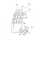
制御対象とする関節は図12に示す多指の関節MP・PIP、母指の関節MP・IPの計8関節とし、各関節は独立して制御する。制御方法はその節と末節にかかる荷重がある一定値よりも大きい場合には、その部位に最も近い根元の関節を伸展駆動させ、その節と末節にかかる荷重がある一定値よりも小さい場合には、その部位に最も近い根元の関節を屈曲駆動させることとした。駆動の際の指令角は曲率関数を用いて算出した。曲率関数とは、予め図13(b)に示すように、作業対象物の50〜∞mmの曲率に沿うように関節角を設定し、曲率と関節角との関係性を関数化したものである。図14に示すように、根元の関節MPについて多項式(I1)が成り立ち、関節PIPについて多項式(I3)が成り立つ。(2.2 Control structure for finger compliance control)
The joints to be controlled are a total of eight joints, the multi-finger joint MP / PIP and the thumb joint MP / IP shown in FIG. 12, and each joint is controlled independently. When the load applied to the node and the last node is greater than a certain value, the control method is to drive the base joint closest to that part to extend, and when the load applied to that node and the last node is less than a certain value. Decided to drive the joint at the root closest to that part. The command angle at the time of driving was calculated using a curvature function. As shown in FIG. 13B, the curvature function is a function in which the joint angle is set so as to follow the curvature of 50 to ∞ mm of the work object, and the relationship between the curvature and the joint angle is converted into a function. is there. As shown in FIG. 14, the polynomial (I1) is established for the root joint MP, and the polynomial (I3) is established for the joint PIP.
本実施形態によれば、アーム部20と、アーム部20先端のハンド部30と、アーム部20の制御目標を設定するアーム制御部200とを備えたマニュピレータ10において、ハンド部30は、アーム部20先端に対して取付けられる掌部40と、掌部40に対して可動の少なくとも1つの指部50と、作業対象物Oの作業対象面に対する掌部40の接触領域における2箇所以上の点の押付力を検出するタクタイルセンサ42と、作業対象物Oの作業対象面に対する指部50の接触領域における点の押付力を検出するタクタイルセンサ53と、指部50の掌部40に対する位置及び姿勢を検出する力覚センサ52とを有するため、掌部40の接触領域における2箇所以上の点の押付力、指部50の接触領域における点の押付力並びに指部50の掌部40に対する位置及び姿勢といったハンド部30における各種の情報を検出することができる。さらに、アーム制御部200は、タクタイルセンサ42が検出した掌部40の接触領域における点の押付力と、タクタイルセンサ53が検出した指部50の接触領域における点の押付力と、力覚センサ52が検出した指部50の掌部40に対する位置及び姿勢とに基づいて、アーム部20の制御目標を設定するため、ハンド部30における各種の情報をフィードバックしてアーム部20の制御が行なわれることになり、面倣い作業等のハンド部30での多点接触による動作を可能とし、ハンド部30での多点接触による押付力の力制御をより容易に行なうことが可能となる。 According to the present embodiment, in the
すなわち、図33に示す従来のマニュピレータ制御系900では、アーム制御部200によるアーム制御とハンド制御部300によるハンド制御とが協調しておらず、人間の前腕部等の作業対象物に指先部だけで接触しており、接触面積が小さく作業効率が悪いという欠点がある。しかし、本実施形態では、アーム制御部200によるアーム制御とハンド制御部300によるハンド制御とを協調させて力制御を行うことにより、多点での倣い作業と力制御とを容易に行なうことが可能となる。 That is, in the conventional
また、本実施形態によれば、アーム制御部200は、掌部40の接触領域における接触圧の分布状態が目標の状態に近づくように、例えば、掌部40の接触領域における接触圧力重心PCGが、掌部40の接触領域における幾何学的重心GCGと一致するようにアーム部20の制御目標を設定するため、掌部40の接触領域における接触圧力重心GCGが、ベース部の接触領域における幾何学的重心GCGと一致した押圧が可能となり、掌部40の接触領域において、より偏りのない作業対象物の形状に合ったアーム部20の制御が可能となる。Further, according to this embodiment, the
また、本実施形態によれば、指部50の制御目標を設定するハンド制御部300は、タクタイルセンサ53が検出した指部50の接触領域における点の押付力に基づいて、指部50の接触領域における点の押付力が所定の目標値と一致するように、例えば、指部50の接触領域における点の押付力が一定となるように、指部50の掌部40に対する位置及び姿勢をコンプライアンス制御により制御するように指部50の制御目標を設定するため、様々な形状の作業対象物Oに対して柔軟に適応して、指部50の接触領域の押付力を一定にすることが可能となる。 Further, according to the present embodiment, the
さらに、本実施形態によれば、アーム制御部200は、アーム部20の制御目標としてアーム部20の姿勢及び作業対象物に対して加える力を制御目標として設定するため、アーム部20の姿勢及び作業対象物に対して加える力の制御は、ハンド部30における各種の情報をフィードバックして行なわれることになり、面倣い作業等のハンド部30での多点接触による動作を可能とし、ハンド部での多点接触による押付力の力制御をより容易に行なうことが可能となる。 Furthermore, according to the present embodiment, the
(実験例)
以下、本実施形態の実験例について説明する。上述の実施形態のマニュピレータ10を用いて清拭作業を行い評価した。試験用の作業対象物としては、図15(a)〜(c)に示すような様々な曲率の曲面、凹凸を有する作業対象物O,O’,O”を用いた。対象部位はφ100及びφ200の円柱部に対して、横方向へのスライド、及び指先方向への回りこみを行なった。また、凹凸に対しても回り込む清拭作業を行なった。(Experimental example)
Hereinafter, experimental examples of the present embodiment will be described. A wiping operation was performed and evaluated using the
マニュピレータ10の制御方法は、本発明の手法を用いた制御と、従来手法を模擬し、ハンド部30を平面として扱い、手先の押付方向及び位置の制御のみを用いた制御の二通りで比較を行った。試験装置としては、図16に示すように、重ねた清拭タオルTの間に分布型圧力センサSを配し、清拭作業時の作業対象物O,O’,O”にかかる圧力分布状況を計測する事により行なった。評価項目としては、接触面積と圧力偏在とし、これらを計測し安全性・作業性の観点から評価を行なった。 The control method of the
なお、圧力分布センサの諸元は、
メーカー:NITTA
型番(商品名):I−Scan150−0.5
空間分解能[mm]:3.75
セル数:1936
感圧部分サイズ[mm]:165×165
厚さ[mm]:0.1
感圧範囲[kgf/cm2]:0.05〜0.5
圧力分解能[bit]:8
サンプリング周期[ms]:10The specifications of the pressure distribution sensor are as follows:
Manufacturer: NITTA
Model number (product name): I-Scan150-0.5
Spatial resolution [mm]: 3.75
Number of cells: 1936
Pressure-sensitive part size [mm]: 165 x 165
Thickness [mm]: 0.1
Pressure sensitive range [kgf / cm2 ]: 0.05 to 0.5
Pressure resolution [bit]: 8
Sampling period [ms]: 10
図15(a)に示す二つの異なる曲率(φ100及びφ200)を有し当該異なる曲率の部位に段差を有する作業対象物O、図15(b)に示す当該異なる曲率の部位がなだらかな傾斜となっている作業対象物O’、及び図15(c)に示すφ200の曲面に半径60mm、高さ30mmの凸部Pを有する作業対象物O”に対して、ハンド部30側面方向、及び指先方向へ清拭を行なった。 A work object O having two different curvatures (φ100 and φ200) shown in FIG. 15A and having a step at the different curvature portions, and the different curvature portions shown in FIG. For the work object O ′ and the work object O ″ having a convex part P having a radius of 60 mm and a height of 30 mm on the curved surface of φ200 shown in FIG. Wiping in the direction.
(実験例1)
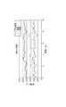
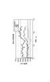
φ100及びφ200の二つの曲率をなだらかにせず段差状にした作業対象物Oに対して、本発明の手法で制御されたマニュピレータ10により、ハンド部30側面方向への清拭を行なった。結果を図17(a)〜(f)、図18及び図19に示す。図17〜19より、動作は段差に対して各指が独立して倣い、荷重は全ての部位においてほぼ一定に収まり、接触面積は全ての部位においてほぼ一定に収まり、荷重中心はほぼ手指の中心に納まっていることが判る。(Experimental example 1)
The work object O having two steps of φ100 and φ200 that were not stepped gently but stepped was wiped in the side direction of the
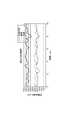
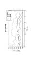
(比較例1)
φ100及びφ200の二つの曲率をなだらかにせず段差状にした作業対象物Oに対して、アーム手先姿勢制御をOFFにしたマニュピレータ10により、ハンド部30側面方向への清拭を行なった。結果を図20(a)〜(d)、図21及び図22に示す。図20〜22より、動作は手先姿勢修正制御が入っていないために掌部40の接触が維持できず、荷重は手指全体ではほぼ一定だが、掌部40及び指部50それぞれでの変化が激しく、接触面積は全ての部位において大きな変化があり、安定した接触維持ができず、荷重中心はハンド幾何学中心GCGから大きく逸脱していることが判る。(Comparative Example 1)
With respect to the work object O having a stepped shape without making the two curvatures of φ100 and φ200 gentle, the
(実験例2)
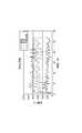
φ100及びφ200の二つの曲率をなだらかな傾斜にした作業対象物O’に対して、本発明の手法で制御されたマニュピレータ10により、ハンド部30側面方向への清拭を行なった。結果を図23(a)〜(d)、図24及び図25に示す。図23〜25より、動作は比較的小さな曲率から平面への移行においても安定して倣い、荷重は全ての部位においてほぼ一定に収まり、接触面積は全ての部位においてほぼ一定に収まり、荷重中心はほぼ手指の中心に納まっていることが判る。(Experimental example 2)
The work object O ′ having the two curvatures φ100 and φ200 having a gentle inclination was wiped in the direction of the side of the
(実験例3)
φ100及びφ200の二つの曲率をなだらかな傾斜にした作業対象物O’に対して、φ200の曲率の箇所で本発明の手法で制御されたマニュピレータ10により、指先方向への清拭を行なった。また、指先方向から手首方向へ戻す清拭も行なった。結果を図26(a)〜(d)、図27(a)〜(d)、図28及び図29に示す。図26〜29より、動作は手先の角度が0〜80deg程度変化し、手先角度が80deg付近になるとやや振動したが、おおむね安定して倣っていることが判る。また、掌部40の荷重が手先角度が増えるにつれて徐々に大きくなる傾向があり、指部50の荷重が他の動作に比べて低いことが判る。接触面積は掌部40の面積は手先角度が増えるにつれ徐々に大きくなる傾向があり、指部50の面積は他の動作に比べて小さいことが判る。荷重中心は掌部40に偏りがちではあるが、変化量は少ないことが判る。(Experimental example 3)
The work object O ′ having the two curvatures of φ100 and φ200 having a gentle inclination was wiped in the fingertip direction by the
(実験例4)
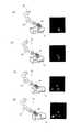
図15(c)に示すφ200の曲面に半径60mm、高さ30mmの凸部Pを有する作業対象物O”に対して、本発明の手法で制御されたマニュピレータ10により、指先方向へ回り込む清拭を行なった。結果を図30(a)〜(e)、図31、及び図32に示す。図30〜32より、動作は人差し指、中指が凸部に接触したが、各指が独立に動作し作業対象物O”に倣っていることが判る。荷重は、掌部40の荷重が、手先角度が増えるにつれ徐々に大きくなる傾向があることが判り、反対に指部50の荷重は手先角度が増えるにつれ小さくなっていくことが判る。接触面積は凸部Pがあると指が振動するため、接触面積も波立っていることが判る。荷重中心は凸部Pに入ると一旦指部50側に荷重中心が移動するが、しばらくすると中心に戻ってくることが判る。(Experimental example 4)
Wiping the work object O ″ having a convex portion P having a radius of 60 mm and a height of 30 mm on the curved surface of φ200 shown in FIG. 15C by the
以上の実験例の結果をまとめると、安全性については、曲面に対し常にハンド部30全体がなじむことにより、動作開始時から終了時にわたり常に接色面積が大きくなった。また、凹凸に対し指部50がなじむ事により、局所的圧力偏在を防ぎ、圧力分散することが確認された。また、作業性については、本実施形態の制御手法により、接触面積は大きくなり、圧力偏在も少ないため、清拭面積の増大及び拭き残し箇所の減少といった効果が確認された。特に、曲面においては接触面積の積分値は本実施形態の制御手法による制御有りと無しとでは2倍程度の差が確認され、本実施形態の制御手法の効果が大きく現われる結果となった。 Summarizing the results of the above experimental examples, regarding the safety, the
尚、本発明は、上記した実施の形態に限定されるものではなく、本発明の要旨を逸脱しない範囲内において種々変更を加え得ることは勿論である。 It should be noted that the present invention is not limited to the above-described embodiment, and it is needless to say that various modifications can be made without departing from the gist of the present invention.
10…マニュピレータ、20…アーム部、21…受動柔軟関節、22…衝突安全被覆・接触センサ、23…力覚センサ、30…ハンド部、40…掌部、41…柔軟肉、42…タクタイルセンサ、50…指部、51…受動柔軟関節、52…力覚センサ、100…マニュピレータ制御系、200…アーム制御部、201…端部位置検出部、202…端部姿勢検出部、203…端部発生力検出部、204…位置制御部、205…姿勢制御部、206…力制御部、250…アーム駆動部、300…ハンド制御部、301…関節角度検出部、302…圧力検出部、303…ハンド制御部、350…ハンド駆動部、401…手首力センサ、402…掌接触状態、403…手指接触状態、404…姿勢制御、405…圧力制御、406…指関節コンプライアンス制御、520…アーム、521…手先位置、522…手首力情報、523…位置制御、530…ハンド、531…接触圧情報、532…関節角度、900…マニュピレータ制御系、A…姿勢制御、B…力制御、C…手指コンプライアンス制御。DESCRIPTION OF
Claims (2)
Translated fromJapanese前記第1リンク部に対して相対運動する第2リンク部と、
前記第1リンク部の接触領域における接触荷重を検出する第1接触荷重検出部と、
前記第2リンク部の接触領域における接触荷重を検出する第2接触荷重検出部と、
前記第1リンク部の制御目標を設定する第1リンク部制御目標設定部と、
を備え、
前記第1リンク部制御目標設定部は、
前記第1接触荷重検出部の接触荷重の検出値と、前記第2接触荷重検出部の接触荷重の検出値との差分を低減させるように、前記第1リンク部の制御目標を設定し、
前記第1リンク部の接触領域、前記第2リンク部の接触領域、及び前記第1リンク部と前記第2リンク部とを合わせた全接触領域の少なくともいずれかにおける接触圧の分布状態が目標の状態に近づくように前記第1リンク部の制御目標を設定する、ロボット装置。A first link part;
A second link portion that moves relative to the first link portion;
A first contact load detection unit for detecting a contact load in a contact region of the first link unit;
A second contact load detection unit for detecting a contact load in a contact region of the second link unit;
A first link unit control target setting unit for setting a control target for the first link unit;
With
The first link unit control target setting unit includes:
A control target of the first link unit is set so as to reduce a difference between a contact load detection value of the first contact load detection unit and a contact load detection value of the second contact load detection unit;
The distribution state of the contact pressure in at least one of the contact area of the first link part, the contact area of the second link part, and the total contact area including the first link part and the second link part is a target. The robot apparatuswhich sets the control target of the said 1st link part so that a state may be approached .
Priority Applications (2)
| Application Number | Priority Date | Filing Date | Title |
|---|---|---|---|
| JP2008309798AJP5281377B2 (en) | 2008-12-04 | 2008-12-04 | Robot equipment |
| US12/631,100US8442678B2 (en) | 2008-12-04 | 2009-12-04 | Robotic device |
Applications Claiming Priority (1)
| Application Number | Priority Date | Filing Date | Title |
|---|---|---|---|
| JP2008309798AJP5281377B2 (en) | 2008-12-04 | 2008-12-04 | Robot equipment |
Publications (2)
| Publication Number | Publication Date |
|---|---|
| JP2010131702A JP2010131702A (en) | 2010-06-17 |
| JP5281377B2true JP5281377B2 (en) | 2013-09-04 |
Family
ID=42229586
Family Applications (1)
| Application Number | Title | Priority Date | Filing Date |
|---|---|---|---|
| JP2008309798AActiveJP5281377B2 (en) | 2008-12-04 | 2008-12-04 | Robot equipment |
Country Status (2)
| Country | Link |
|---|---|
| US (1) | US8442678B2 (en) |
| JP (1) | JP5281377B2 (en) |
Families Citing this family (35)
| Publication number | Priority date | Publication date | Assignee | Title |
|---|---|---|---|---|
| JP4643429B2 (en)* | 2005-12-13 | 2011-03-02 | 本田技研工業株式会社 | Hand device |
| FR2930905B1 (en)* | 2008-05-09 | 2010-10-01 | Bia | ANKLE FOR HUMANOIDE ROBOT |
| US10532466B2 (en)* | 2008-08-22 | 2020-01-14 | Titan Medical Inc. | Robotic hand controller |
| US8332072B1 (en) | 2008-08-22 | 2012-12-11 | Titan Medical Inc. | Robotic hand controller |
| US8619008B2 (en) | 2009-02-13 | 2013-12-31 | Global Oled Technology Llc | Dividing pixels between chiplets in display device |
| JP5528095B2 (en)* | 2009-12-22 | 2014-06-25 | キヤノン株式会社 | Robot system, control apparatus and method thereof |
| JP5505138B2 (en)* | 2010-07-05 | 2014-05-28 | 株式会社安川電機 | Robot apparatus and gripping method using robot apparatus |
| KR101308373B1 (en)* | 2010-11-17 | 2013-09-16 | 삼성전자주식회사 | Method of controlling robot |
| US8777818B1 (en)* | 2010-12-22 | 2014-07-15 | Larry E. Tate, Jr. | Training device |
| US8783622B2 (en)* | 2011-03-09 | 2014-07-22 | Raytheon Company | Methods and apparatus for a grappling device |
| CN102303316B (en)* | 2011-04-13 | 2013-08-14 | 清华大学 | Multi-sensor feedback adaptive robot finger device and control method thereof |
| US9815193B2 (en) | 2011-06-27 | 2017-11-14 | Delaware Capital Formation, Inc. | Electric motor based holding control systems and methods |
| JP5767563B2 (en)* | 2011-11-02 | 2015-08-19 | 本田技研工業株式会社 | Multi-finger type hand device |
| US9004559B2 (en) | 2012-11-09 | 2015-04-14 | Irobot Corporation | Compliant underactuated grasper |
| US9089977B2 (en) | 2012-11-09 | 2015-07-28 | Irobot Corporation | Compliant underactuated grasper |
| US8991885B2 (en) | 2012-11-09 | 2015-03-31 | Irobot Corporation | Compliant underactuated grasper |
| JP5902664B2 (en)* | 2013-12-25 | 2016-04-13 | ファナック株式会社 | Human cooperative industrial robot with protective member |
| US20150283709A1 (en)* | 2014-04-08 | 2015-10-08 | Sergei Dalakian | Industrial Robot Arm |
| US9403273B2 (en)* | 2014-05-23 | 2016-08-02 | GM Global Technology Operations LLC | Rapid robotic imitation learning of force-torque tasks |
| US9283676B2 (en)* | 2014-06-20 | 2016-03-15 | GM Global Technology Operations LLC | Real-time robotic grasp planning |
| CN105983974B (en)* | 2015-02-06 | 2018-04-17 | 赛恩倍吉科技顾问(深圳)有限公司 | Manipulator, the preparation method of the manipulator and the robot with the manipulator |
| CN105983964B (en)* | 2015-02-06 | 2018-04-17 | 赛恩倍吉科技顾问(深圳)有限公司 | Manipulator, the preparation method of the manipulator and the robot with the manipulator |
| WO2017033365A1 (en)* | 2015-08-25 | 2017-03-02 | 川崎重工業株式会社 | Remote control robot system |
| FR3043004B1 (en)* | 2015-10-29 | 2017-12-22 | Airbus Group Sas | METHOD FOR ORIENTATION OF AN EFFECTOR WITH AN ASSEMBLY TOOL IN RELATION TO A SURFACE |
| US9744677B2 (en) | 2015-11-05 | 2017-08-29 | Irobot Corporation | Robotic fingers and end effectors including same |
| CN205683134U (en)* | 2016-04-09 | 2016-11-16 | 深圳市兼明科技有限公司 | Robot finger based on conductive sponge |
| CN105708551A (en)* | 2016-04-09 | 2016-06-29 | 深圳市兼明科技有限公司 | Control method of robot fingers based on conductive sponge |
| JP6444942B2 (en) | 2016-05-26 | 2018-12-26 | ファナック株式会社 | Robot with a tool having a shock absorbing member |
| US20180021949A1 (en)* | 2016-07-20 | 2018-01-25 | Canon Kabushiki Kaisha | Robot apparatus, robot controlling method, program, and recording medium |
| CN109285188B (en)* | 2017-07-21 | 2020-04-21 | 百度在线网络技术(北京)有限公司 | Method and apparatus for generating position information of target object |
| CN107336241B (en)* | 2017-08-08 | 2020-10-16 | 智造未来(北京)机器人系统技术有限公司 | Manipulator control device, manipulator control method, and manipulator device |
| CN111093914B (en)* | 2017-08-14 | 2023-01-03 | 肯塔泰尔私人有限公司 | Friction-based tactile sensor for measuring clamping safety |
| JP6881268B2 (en)* | 2017-12-05 | 2021-06-02 | トヨタ自動車株式会社 | Gripping device, grip determination method and grip determination program |
| CN108873925B (en)* | 2018-08-02 | 2021-08-24 | 深圳市吉影科技有限公司 | A constant pitch angle motion control method and device for an underwater unmanned aerial vehicle |
| CN114750153B (en)* | 2022-04-13 | 2024-03-19 | 上海电气集团股份有限公司 | Motion control system for robot arm, cooperative robot and storage medium |
Family Cites Families (9)
| Publication number | Priority date | Publication date | Assignee | Title |
|---|---|---|---|---|
| JP2737325B2 (en) | 1989-12-14 | 1998-04-08 | 富士通株式会社 | Robot trajectory generation method |
| US5631861A (en)* | 1990-02-02 | 1997-05-20 | Virtual Technologies, Inc. | Force feedback and texture simulating interface device |
| JP3742876B2 (en)* | 2002-02-25 | 2006-02-08 | 国立大学法人岐阜大学 | Robot hand, gripping control method of robot hand, robot and robot control method |
| CA2500005C (en)* | 2002-09-26 | 2011-12-06 | Barrett Technology, Inc. | Intelligent, self-contained robotic hand |
| JP4211701B2 (en)* | 2004-07-21 | 2009-01-21 | トヨタ自動車株式会社 | Robot hand gripping control device |
| JP2006159320A (en)* | 2004-12-03 | 2006-06-22 | Sharp Corp | Robot hand |
| JP2006321015A (en)* | 2005-05-19 | 2006-11-30 | Toyota Motor Corp | Robot hand device |
| JP4643429B2 (en)* | 2005-12-13 | 2011-03-02 | 本田技研工業株式会社 | Hand device |
| WO2008058061A2 (en)* | 2006-11-03 | 2008-05-15 | President And Fellows Of Harvard College | Robust compliant adaptive grasper and method of manufacturing same |
- 2008
- 2008-12-04JPJP2008309798Apatent/JP5281377B2/enactiveActive
- 2009
- 2009-12-04USUS12/631,100patent/US8442678B2/enactiveActive
Also Published As
| Publication number | Publication date |
|---|---|
| US20100139437A1 (en) | 2010-06-10 |
| US8442678B2 (en) | 2013-05-14 |
| JP2010131702A (en) | 2010-06-17 |
Similar Documents
| Publication | Publication Date | Title |
|---|---|---|
| JP5281377B2 (en) | Robot equipment | |
| JP7719155B2 (en) | Robot system, control method, article manufacturing method, control program, and recording medium | |
| JP6312264B2 (en) | Constraints on robot manipulators with redundant degrees of freedom | |
| US9517562B2 (en) | Robot controller, robot system, robot control method | |
| US8977392B2 (en) | Robot control device, robot control method, robot control program, and robot system | |
| JP5733882B2 (en) | Robot and its cooperative work control method | |
| US9122275B2 (en) | Robot and control method thereof | |
| JP6498597B2 (en) | Mobile robot controller | |
| WO2016073367A1 (en) | Position/force control of a flexible manipulator under model-less control | |
| JP2017159426A (en) | Robot control device, robot, and robot system | |
| JP7740248B2 (en) | Information processing device, information processing method, and program | |
| Delgado et al. | In-hand recognition and manipulation of elastic objects using a servo-tactile control strategy | |
| Navarro et al. | A framework for intuitive collaboration with a mobile manipulator | |
| JP6003312B2 (en) | Robot system | |
| Kobayashi et al. | Hand/arm robot teleoperation by inertial motion capture | |
| Doulgeri et al. | Force position control for a robot finger with a soft tip and kinematic uncertainties | |
| JP2013094947A (en) | Robot arm | |
| JP6270334B2 (en) | Robot control apparatus and method | |
| Kapadia et al. | Teleoperation control of a redundant continuum manipulator using a non-redundant rigid-link master | |
| Frigola et al. | Human-robot interaction based on a sensitive bumper skin | |
| Jalani et al. | Active robot hand compliance using operational space and Integral Sliding Mode Control | |
| JP2019126879A (en) | Gripping device | |
| JP2005329476A (en) | Method and apparatus for controlling operation member | |
| Luo et al. | On-line adaptive control for minimizing slippage error while mobile platform and manipulator operate simultaneously for robotics mobile manipulation | |
| Lee et al. | Symmetry-Based Modeling and Hybrid Orientation-Force Control of Wearable Cutaneous Haptic Device |
Legal Events
| Date | Code | Title | Description |
|---|---|---|---|
| A621 | Written request for application examination | Free format text:JAPANESE INTERMEDIATE CODE: A621 Effective date:20111107 | |
| A977 | Report on retrieval | Free format text:JAPANESE INTERMEDIATE CODE: A971007 Effective date:20121220 | |
| A131 | Notification of reasons for refusal | Free format text:JAPANESE INTERMEDIATE CODE: A131 Effective date:20130122 | |
| A521 | Request for written amendment filed | Free format text:JAPANESE INTERMEDIATE CODE: A523 Effective date:20130319 | |
| TRDD | Decision of grant or rejection written | ||
| A01 | Written decision to grant a patent or to grant a registration (utility model) | Free format text:JAPANESE INTERMEDIATE CODE: A01 Effective date:20130507 | |
| A61 | First payment of annual fees (during grant procedure) | Free format text:JAPANESE INTERMEDIATE CODE: A61 Effective date:20130524 | |
| R151 | Written notification of patent or utility model registration | Ref document number:5281377 Country of ref document:JP Free format text:JAPANESE INTERMEDIATE CODE: R151 | |
| R250 | Receipt of annual fees | Free format text:JAPANESE INTERMEDIATE CODE: R250 | |
| R250 | Receipt of annual fees | Free format text:JAPANESE INTERMEDIATE CODE: R250 | |
| R250 | Receipt of annual fees | Free format text:JAPANESE INTERMEDIATE CODE: R250 | |
| R250 | Receipt of annual fees | Free format text:JAPANESE INTERMEDIATE CODE: R250 | |
| R250 | Receipt of annual fees | Free format text:JAPANESE INTERMEDIATE CODE: R250 | |
| R250 | Receipt of annual fees | Free format text:JAPANESE INTERMEDIATE CODE: R250 | |
| R250 | Receipt of annual fees | Free format text:JAPANESE INTERMEDIATE CODE: R250 | |
| R250 | Receipt of annual fees | Free format text:JAPANESE INTERMEDIATE CODE: R250 | |
| R250 | Receipt of annual fees | Free format text:JAPANESE INTERMEDIATE CODE: R250 | |
| R250 | Receipt of annual fees | Free format text:JAPANESE INTERMEDIATE CODE: R250 |