JP5281366B2 - Bolt fastening device - Google Patents
Bolt fastening deviceDownload PDFInfo
- Publication number
- JP5281366B2 JP5281366B2JP2008284128AJP2008284128AJP5281366B2JP 5281366 B2JP5281366 B2JP 5281366B2JP 2008284128 AJP2008284128 AJP 2008284128AJP 2008284128 AJP2008284128 AJP 2008284128AJP 5281366 B2JP5281366 B2JP 5281366B2
- Authority
- JP
- Japan
- Prior art keywords
- bolt
- tensioner
- arm
- screwed
- hole
- Prior art date
- Legal status (The legal status is an assumption and is not a legal conclusion. Google has not performed a legal analysis and makes no representation as to the accuracy of the status listed.)
- Expired - Fee Related
Links
- 238000013459approachMethods0.000claimsdescription7
- 230000008602contractionEffects0.000claimsdescription3
- 238000000034methodMethods0.000abstractdescription7
- 238000002513implantationMethods0.000description22
- 238000007726management methodMethods0.000description6
- 230000005540biological transmissionEffects0.000description3
- 230000006835compressionEffects0.000description3
- 238000007906compressionMethods0.000description3
- 238000010008shearingMethods0.000description3
- 230000007547defectEffects0.000description2
- 239000000463materialSubstances0.000description2
- 230000001276controlling effectEffects0.000description1
- 239000012530fluidSubstances0.000description1
- 230000002093peripheral effectEffects0.000description1
- 230000001105regulatory effectEffects0.000description1
- 230000002195synergetic effectEffects0.000description1
Images


Landscapes
- Details Of Spanners, Wrenches, And Screw Drivers And Accessories (AREA)
Abstract
Description
Translated fromJapanese本発明は、被締結体に円弧状又は円形に配置された複数のボルト孔に、軸方向の引張り力を付与し軸方向の伸びを与えた状態でボルトを螺着させるボルト締結装置に関し、多数のボルト孔のボルト締結作業を安価な装置で自動化にして、作業工数を低減可能にしたものである。The present invention, a plurality of bolt holes arranged in an arc or circle fastened member, relates boltingYuiSo location for screwing the bolt in the state gave elongation impart tensile force in the axial direction axially The bolt fastening operation of a large number of bolt holes is automated with an inexpensive device, so that the number of work steps can be reduced.
従来、ボルトの締付力を管理する場合、ボルトに螺合するナットの締め付けトルクを管理するトルク管理が行なわれていた。しかしながら、このようなトルク管理では、ボルト及びナットのねじ加工の精度、又はボルト、ナット若しくは被締結体の材質等によって摩擦係数が大きく変化するため、締付力を高精度に管理することが困難であった。 Conventionally, when managing the tightening force of a bolt, torque management for managing the tightening torque of a nut screwed into the bolt has been performed. However, in such torque management, it is difficult to manage the tightening force with high accuracy because the coefficient of friction changes greatly depending on the accuracy of screw processing of the bolt and nut or the material of the bolt, nut or fastened body. Met.
そこで、トルク管理方式に代えて、被締結体に穿設されたボルト孔に仮螺合させたボルトの先端側にボルトテンショナを用いて所要の軸力(軸方向の引張り力)を加えた後、ナットを該ボルトにねじ込んで被締結体の表面に当接させ、その後ボルトに対する軸力を解除する、いわゆる軸力管理によるボルト締結方法が多く採用されてきた。これによって、大きな締付力が得られるとともに、締付力の管理を容易に行なうことができる。 Therefore, instead of the torque management method, after applying the required axial force (a tensile force in the axial direction) using a bolt tensioner to the front end side of the bolt temporarily screwed into the bolt hole drilled in the fastened body Many bolt fastening methods based on so-called axial force management, in which a nut is screwed into the bolt and brought into contact with the surface of the body to be fastened and then the axial force on the bolt is released, have been adopted. Thereby, a large tightening force can be obtained, and the tightening force can be easily managed.
特許文献1(特開平3−103610号公報)及び特許文献2(特開平11−183280号公報)には、前記軸力管理を採用したボルト締結装置が開示されている。特許文献1は、植え込みボルトを被締結体に螺着させる場合の例が図示され、特許文献2には頭部を有する六角ボルトを被締結体に螺着させる場合の例が図示されている。 Patent Document 1 (Japanese Patent Laid-Open No. 3-103610) and Patent Document 2 (Japanese Patent Laid-Open No. 11-183280) disclose a bolt fastening device employing the axial force management.
しかし、風力発電装置の風車部分でブレードのピッチ角を可変に支持する環状の軸受をロータヘッドに取り付ける部分や、大型クレーン車でクレーンを回動可能に支持する基盤部分等のように、多数の締結ボルトが円形に配置されている場合、前記軸力管理によりボルトテンショナを用いてボルト締結すると、ボルト1個々ごとに逐一ボルトテンショナを配置して締結作業を行なっていくため、多くの作業時間を要する。 However, there are many parts such as a part that attaches an annular bearing that variably supports the pitch angle of the blade to the rotor head in the wind turbine part of the wind turbine generator, and a base part that rotatably supports the crane in a large crane car. When the fastening bolts are arranged in a circle, if the bolt tensioner is used to fasten the bolts by the axial force management, the bolt tensioner is arranged for each bolt one by one, so that a lot of work time is required. Cost.
かかる作業を短時間で行なおうとすると、ボルト孔の数に見合う複数のボルトテンショナを一度に配置して行なわざるを得ない。この場合、1個のボルトテンショナの価格が高価なため、ボルト締結設備が非常に高価となるという問題があった。 If this work is to be performed in a short time, a plurality of bolt tensioners corresponding to the number of bolt holes must be arranged at a time. In this case, since the price of one bolt tensioner is expensive, there is a problem that the bolt fastening facility becomes very expensive.
また、ロボットアームの先端にボルトテンショナを装着してボルト締結作業を行なおうとすると、ロボットアームに1個のボルトテンショナを装着した場合はボルトテンショナのボルト締結位置への位置決めは容易であるが、ロボットアームに複数のボルトテンショナを装着して複数のロボットアームで同時にボルト締結作業を行なう場合、各ボルトテンショナの位置決めが困難になるという問題があった。
また、風車発電装置のロータヘッドの場合、ボルト取付け位置に3mm以下の公差が発生するが、この公差によってボルトテンショナがボルトの位置に合わなくなり、ボルト締結作業ができなくなるという問題がある。Also, if a bolt tensioner is attached to the tip of the robot arm and the bolt fastening operation is performed, the positioning of the bolt tensioner to the bolt fastening position is easy when one bolt tensioner is attached to the robot arm. When a plurality of bolt tensioners are attached to a robot arm and a bolt fastening operation is simultaneously performed by a plurality of robot arms, there is a problem that positioning of each bolt tensioner becomes difficult.
Further, in the case of a rotor head of a wind turbine generator, a tolerance of 3 mm or less is generated at the bolt mounting position, but this tolerance causes a problem that the bolt tensioner does not match the position of the bolt and the bolt fastening operation cannot be performed.
本発明は、かかる従来技術の課題に鑑み、被締結体に多数のボルト孔を円弧状又は円形に配置し、該ボルト孔に軸方向の引張り力を付与して伸びを与えたボルトを螺着させる場合に、このボルト締結作業を自動化して、低コストでかつ短時間でボルト締結を可能とすることを目的とする。
また、複数のボルトテンショナを用いてボルト締結作業を同時に行なう場合でも、個々のボルトテンショナの位置決めを容易にすることを目的とする。
また、ボルトの取付け位置に公差が生じても、この公差を吸収してボルト締結作業を可能にすることを目的とする。In view of the problems of the prior art, the present invention arranges a large number of bolt holes in an arcuate shape or a circular shape in a body to be fastened, and screwes bolts that are stretched by applying an axial tensile force to the bolt holes. The purpose of this is to automate this bolt fastening operation to enable bolt fastening at a low cost and in a short time.
It is another object of the present invention to facilitate positioning of individual bolt tensioners even when a bolt fastening operation is simultaneously performed using a plurality of bolt tensioners.
Moreover, even if a tolerance arises in the attachment position of a volt | bolt, it aims at absorbing this tolerance and enabling a bolt fastening operation | work.
また、本発明のボルト締結装置は、前記本発明方法の実施に直接使用する装置であり、
被締結体に円弧状に配置された複数のボルト孔に、軸方向の引張り力を付与した状態でボルトを螺着させるボルト締結装置において、
複数のボルトを結ぶ円弧の中心を回転中心とするように被締結体に対して回転可能に配置された腕及び該腕を回転駆動する手段と、
該腕に前記ボルト孔に対向可能な位置に設けられ、ボルト孔に仮螺合されたボルトに係止固定される固定部、及びボルトに固定された固定部にボルトから離れる方向に荷重を付加する手段を備えたボルトテンショナと、
ボルトテンショナをボルトに接近させ該固定部をボルトに固定させる手段と、
ボルトテンショナを各ボルト孔に対向する位置に位置決めする手段と、を備え、
該ボルト孔に仮螺合したボルトにボルトテンショナで軸方向の引張り力を付与してボルトに伸びを与え、伸長したボルトをボルト孔にさらにねじ込むか、又は該ボルトに仮螺合されたナットをさらにねじ込むことにより締付力を得るようにし、
前記腕を回転させて該ボルトテンショナにより複数のボルト孔に順々にボルトを螺着させるように構成したものである。The bolt fastening device of the present invention is a device used directly for carrying out the method of the present invention,
In a bolt fastening device in which a bolt is screwed in a state where an axial tensile force is applied to a plurality of bolt holes arranged in an arc shape in a body to be fastened,
An arm rotatably arranged with respect to the fastened body so that the center of an arc connecting a plurality of bolts is the center of rotation, and a means for rotationally driving the arm;
A load is applied to the arm at a position that can be opposed to the bolt hole, and fixed to the bolt that is temporarily screwed into the bolt hole, and to the fixed part that is fixed to the bolt in a direction away from the bolt. A bolt tensioner with means to
Means for causing the bolt tensioner to approach the bolt and fixing the fixing portion to the bolt;
Means for positioning the bolt tensioner at a position facing each bolt hole,
A bolt tensioner is used to apply an axial tensile force to the bolt that is temporarily screwed into the bolt hole to elongate the bolt, and the extended bolt is further screwed into the bolt hole, or a nut that is temporarily screwed into the bolt is attached. Further tightening force is obtained by screwing,
The arm is rotated so that the bolts are sequentially screwed into the plurality of bolt holes by the bolt tensioner.
本発明装置において、かかる構成により、前記腕を回転させてボルトテンショナを各ボルト孔に順々に対向配置させ、ボルト孔に仮螺合したボルトにボルトテンショナを固定させる。そして、ボルトテンショナでボルトに軸方向の引張り力を付与してボルトに伸びを与える。そして、伸長したボルトをボルト孔にさらにねじ込むか、又は該ボルトに仮螺合されたナットをさらにねじ込むことにより締付力を得るようにする。このため、円弧状又は円形に配置された多数のボルト孔に対するボルト締結作業を自動化することができ、締結作業の能率を大幅に向上させることができる。 In the device according to the present invention, with this configuration, the arm is rotated so that the bolt tensioners are sequentially arranged opposite to the respective bolt holes, and the bolt tensioners are fixed to the bolts temporarily screwed into the bolt holes. And the tension | tensile_strength of an axial direction is provided to a volt | bolt with a bolt tensioner, and an elongation is given to a volt | bolt. Then, the tightened force is obtained by further screwing the elongated bolt into the bolt hole or by further screwing the nut temporarily screwed into the bolt. For this reason, the bolt fastening operation | work with respect to many bolt holes arrange | positioned at circular arc shape or circular can be automated, and the efficiency of a fastening operation | work can be improved significantly.
本発明装置において、ボルトテンショナに前記固定部を回転させる手段を設け、固定部をボルトに固定した状態で該固定部を回転させることによりボルト孔にボルトを螺入可能に構成するとよい。ボルト孔へのボルトの仮螺合は作業員が行なってもよいが、ボルトを連続的に供給し送る装置、及びナットを連続的に供給してボルトに仮螺合する装置、ボルトテンショナの固定部を回転させる手段を設ければ、ボルトの仮螺合をボルトテンショナで行なうこともできる。即ち、該固定部にボルトを固定した状態で固定部を回転させることで、ボルトをボルト孔へ仮螺合させることができる。 In the device according to the present invention, it is preferable that the bolt tensioner is provided with means for rotating the fixing portion, and the fixing portion is fixed to the bolt so that the bolt can be screwed into the bolt hole by rotating the fixing portion. The bolt may be temporarily screwed into the bolt hole by an operator, but a device that continuously feeds and feeds the bolt, a device that continuously feeds the nut and temporarily screws the bolt, and fixing the bolt tensioner If means for rotating the part is provided, the bolt can be temporarily screwed with a bolt tensioner. That is, the bolt can be temporarily screwed into the bolt hole by rotating the fixing portion with the bolt fixed to the fixing portion.
該回転手段は、例えば、ボルトテンショナに固定部を回転させる電動モータを設けるとよい。また、ボルトに伸びを与えた後のボルトのねじ込み作業も該回転手段で固定部を回転させることで行なうことができる。 The rotating means may be provided with, for example, an electric motor that rotates the fixed portion of the bolt tensioner. Further, the bolt can be screwed in after the bolt has been stretched by rotating the fixing portion with the rotating means.
これによって、ボルト締結作業を略全面的に自動化することができる。なお、ボルトが植え込みボルトである場合、前記固定部が該植え込みボルトの頭部に形成されたオネジ部に螺合するメネジ部を備え、該オネジ部とメネジ部とを螺合させることにより、該固定部を植え込みボルトに固定させるように構成すれば、固定部への植え込みボルトの固定を容易に行なうことができる。 As a result, the bolt fastening operation can be automated almost entirely. In the case where the bolt is an implanted bolt, the fixing portion includes a female screw portion that is screwed into a male screw portion formed on the head of the implanted bolt, and by screwing the male screw portion and the female screw portion, If the fixing portion is fixed to the implantation bolt, the implantation bolt can be easily fixed to the fixing portion.
また、本発明装置において、前記腕をボルト孔を結ぶ円弧の直径上に配置され回転中心で軸支され両端にボルトテンショナを装着した1個以上の腕で構成するとよい。かかる固定部により、n個の腕を設けることにより、2×n個のボルトテンショナを作動させることができる。これによって、同時に2×n個のボルトを締結することができ、作業能率が飛躍的に向上する。 In the device according to the present invention, the arm may be composed of one or more arms arranged on the diameter of an arc connecting the bolt holes, pivotally supported at the center of rotation, and having bolt tensioners attached to both ends. By providing n arms with such a fixing portion, 2 × n bolt tensioners can be operated. As a result, 2 × n bolts can be fastened at the same time, and the working efficiency is dramatically improved.
また、本発明装置において、ボルトテンショナの位置決め手段を、前記回転中心に対して腕から相対角度を規制されて設けられ、該相対角度上の点から互いに接近又は離反可能でかつボルト締結位置に進退可能に設けられた一対の位置決めバーで構成し、該位置決めバーをボルト孔に螺着されたボルトの間に挿入しボルト側面に当接することにより、ボルトテンショナを締結対象となるボルト孔に位置決めするように構成するとよい。 In the device of the present invention, the bolt tensioner positioning means is provided with a relative angle restricted from the arm with respect to the center of rotation, and can be moved toward and away from each other from a point on the relative angle, and is advanced and retracted to the bolt fastening position. It is composed of a pair of positioning bars provided so that the bolt tensioner is positioned in the bolt hole to be fastened by inserting the positioning bar between the bolts screwed into the bolt holes and contacting the bolt side surfaces. It may be configured as follows.
かかる構成の位置決め手段を用いれば、複数の腕に夫々ボルトテンショナを装着して、複数のボルトテンショナで同時にボルト締結動作を行なう場合でも、位置決め手段と各ボルトテンショナの相対角度を予め規制しておくことにより、1個の位置決め手段で複数のボルトテンショナの位置決めを同時に行なうことができる。
また、電気的なセンサや複雑な制御装置を用いることなしに、簡単な構造の機械的な手段のみで、ボルトテンショナを締結対象となるボルト孔に位置決めすることが可能となる。By using the positioning means having such a configuration, the relative angles between the positioning means and each of the bolt tensioners are regulated in advance even when the bolt tensioners are respectively attached to the plurality of arms and the bolt fastening operation is simultaneously performed by the plurality of bolt tensioners. Thus, the positioning of a plurality of bolt tensioners can be performed simultaneously by one positioning means.
Further, it is possible to position the bolt tensioner in the bolt hole to be fastened with only mechanical means having a simple structure without using an electrical sensor or a complicated control device.
なお、本発明装置において、前記腕の回転駆動手段を、該腕に装着され被締結体に当接してガイドされるガイドローラと、該ガイドローラの回転駆動装置で構成するとよい。
かかる構成とすることにより、腕を被締結体に沿って正確に回転運動させることができる。そのため、ボルトテンショナを各ボルト孔に正確に対向配置することができる。In the device of the present invention, the rotation driving means of the arm may be constituted by a guide roller that is attached to the arm and guided by contact with the body to be fastened, and a rotation driving device of the guide roller.
By setting it as this structure, an arm can be accurately rotationally moved along a to-be-fastened body. Therefore, the bolt tensioner can be disposed so as to face each bolt hole accurately.
また、本発明装置において、腕にリング状支持部材を回動可能に設けると共に、該リング状支持部材の内側に前記ボルトテンショナを弾性体を介して微動可能に設け、
リング状支持部材に錘を取り付け、腕の任意の姿勢に対して該錘を常にリング状支持部材の下方領域に位置させることにより、該弾性体に対してリング状支持部材の荷重が常に同じ方向に加わるように構成するとよい。
前記構成によって、ボルトテンショナが弾性体を介して微動可能に取り付けられるため、ボルトの取付け位置に公差がある場合でも、この公差を吸収してボルトテンショナの固定部をボルト頭部の中心に位置合わせできる。そのため、ボルトテンショナの頭部を確実にボルト頭部に固定することが容易になる。Further, in the device of the present invention, a ring-shaped support member is rotatably provided on the arm, and the bolt tensioner is provided on the inner side of the ring-shaped support member so as to be finely movable via an elastic body.
By attaching a weight to the ring-shaped support member and always positioning the weight in the lower region of the ring-shaped support member for any posture of the arm, the load of the ring-shaped support member is always in the same direction with respect to the elastic body It is good to comprise so that it may join.
With the above configuration, the bolt tensioner is attached through an elastic body so that it can be moved finely, so even if there is a tolerance in the bolt mounting position, this tolerance is absorbed and the fixing portion of the bolt tensioner is aligned with the center of the bolt head. it can. Therefore, it becomes easy to reliably fix the head of the bolt tensioner to the bolt head.
また、弾性体によるボルトテンショナの支持位置が変わると、弾性体に加わるボルトテンショナの自重の方向が異なり、ケースバイケースで弾性体には引張力、圧縮力又はせん断力等が加わることになる。これによって、ボルトテンショナの姿勢が変わり、ボルトの取付け公差を吸収できない場合がある。
これに対し、前記構成により、弾性体に対してリング状支持部材の荷重が常に同じ方向に加わるようにしたため、腕がどの位置にあっても、ボルトテンショナの姿勢が一定となる。これによって、ボルトの取付け公差を吸収して、ボルトに固定部を固定することができる。Further, when the support position of the bolt tensioner by the elastic body is changed, the direction of the weight of the bolt tensioner applied to the elastic body is different, and a tensile force, a compressive force, a shearing force, or the like is applied to the elastic body on a case-by-case basis. As a result, the posture of the bolt tensioner changes, and the bolt mounting tolerance may not be absorbed.
On the other hand, with the above configuration, the load of the ring-shaped support member is always applied to the elastic body in the same direction, so that the position of the bolt tensioner is constant regardless of the position of the arm. Accordingly, it is possible to absorb the mounting tolerance of the bolt and fix the fixing portion to the bolt.
また、ボルトテンショナの固定部にボルトテンショナ本体に対してガタをもたせるようにしても、ボルトの取付け公差を吸収できる。あるいはボルトテンショナの固定部に、ボルトの頭部に形成されたオネジ部に螺合するメネジ部を備えている場合には、該メネジ部開口にメネジ部を拡径する傾斜面を設けるようにしてもよい。これによっても、ボルトの取付け公差を吸収できる。
また、本発明装置において、ボルトの伸び量を計測する手段を設け、ボルトに付与する引張り力とボルトの伸び量、又はボルト螺着後に引張り力を解除した際のボルトの縮み量からボルトの不良を検出するようにするとよい。これによって、ボルト締結作業中にボルトの不良を見出すことができる。In addition, even if the bolt tensioner fixing portion has a backlash with respect to the bolt tensioner body, the mounting tolerance of the bolt can be absorbed. Alternatively, when the fixing portion of the bolt tensioner is provided with a female screw portion that is screwed into the male screw portion formed on the head portion of the bolt, an inclined surface for expanding the female screw portion is provided in the female screw portion opening. Also good. This also absorbs bolt mounting tolerances.
Further, in the device of the present invention, a means for measuring the amount of elongation of the bolt is provided, and the failure of the bolt is determined from the tensile force applied to the bolt and the amount of elongation of the bolt, or the amount of contraction of the bolt when the tensile force is released after the bolt is screwed. Should be detected. Thereby, the defect of a bolt can be found during a bolt fastening operation.
本発明方法によれば、ボルトに軸方向の引張り力を付与するボルトテンショナを装着した腕を複数のボルト孔を結ぶ円弧の中心を回転中心として回転可能に配置するとともに、ボルトテンショナを被締結体に穿設されたボルト孔のひとつに対向配置し、該ボルト孔にボルトを一時的に仮螺合させた後、該ボルトにボルトテンショナを固定し、該ボルトテンショナで該ボルトに軸方向の引張り力を付与してボルトに伸びを与え、伸長したボルトをボルト孔にさらにねじ込むか、又は該ボルトに仮螺合されたナットをさらにねじ込むことにより締付力を得るようにし、該腕を回転させて前記手順でボルトテンショナにより複数のボルト孔に順々にボルトを螺着させるようにしたことにより、円弧状又は円形に配置された複数のボルト孔に対するボルト締結作業において、ボルトテンショナを使用したボルト締付けを低コストで略自動化することができる。これによって、ボルト締結作業を安価な装置で実施できると共に、作業時間を飛躍的に短縮することができる。 According to the method of the present invention, an arm equipped with a bolt tensioner that applies an axial tensile force to a bolt is disposed so as to be rotatable about the center of an arc connecting a plurality of bolt holes, and the bolt tensioner is fastened. The bolt tensioner is fixed to one of the bolt holes formed in the bolt hole, temporarily bolted into the bolt hole, and then a bolt tensioner is fixed to the bolt, and the bolt tensioner is used to pull the bolt in the axial direction. Apply a force to stretch the bolt, and screw the extended bolt into the bolt hole, or screw in the nut that is temporarily screwed into the bolt to obtain a tightening force, and rotate the arm. In the above procedure, the bolts are sequentially screwed into the plurality of bolt holes by the bolt tensioner. In preparative fastening operation can be substantially automated at low cost fastening bolt using the bolt tensioner. As a result, the bolt fastening operation can be performed with an inexpensive device, and the working time can be dramatically shortened.
また、本発明装置によれば、複数のボルトを結ぶ円弧の中心を回転中心とするように被締結体に対して回転可能に配置された腕及び該腕を回転駆動する手段と、該腕に前記ボルト孔に対向可能な位置に設けられ、ボルト孔に仮螺合されたボルトに係止固定される固定部、及びボルトに固定された固定部にボルトから離れる方向に荷重を付加する手段を備えたボルトテンショナと、ボルトテンショナをボルトに接近させ該固定部をボルトに固定させる手段と、ボルトテンショナを各ボルト孔に対向する位置に位置決めする手段と、を備え、該ボルト孔に仮螺合したボルトにボルトテンショナで軸方向の引張り力を付与してボルトに伸びを与え、伸長したボルトをボルト孔にさらにねじ込むか、又は該ボルトに仮螺合されたナットをさらにねじ込むことにより締付力を得るようにし、前記腕を回転させて該ボルトテンショナにより複数のボルト孔に順々にボルトを螺着させるように構成したことにより、円弧状又は円形に配置された複数のボルトに対して、ボルトテンショナを使用したボルト締付作業を低コストで自動化することができ、ボルト締結の作業時間を飛躍的に短縮することができる。 Further, according to the device of the present invention, the arm disposed rotatably with respect to the fastened body so that the center of the arc connecting the plurality of bolts is the center of rotation, the means for rotationally driving the arm, and the arm A fixing portion provided at a position that can be opposed to the bolt hole, and fixed to a bolt temporarily screwed into the bolt hole; and means for applying a load in a direction away from the bolt to the fixing portion fixed to the bolt. A bolt tensioner provided, means for moving the bolt tensioner close to the bolt and fixing the fixing portion to the bolt, and means for positioning the bolt tensioner at a position facing each bolt hole, and temporarily screwing into the bolt hole The bolt is tensioned in the axial direction with a bolt tensioner to elongate the bolt, and the extended bolt is further screwed into the bolt hole, or the nut that is temporarily screwed into the bolt is further screwed A plurality of bolts arranged in an arc or a circle by rotating the arm and screwing the bolts sequentially into the plurality of bolt holes by the bolt tensioner. The bolt tightening operation using the bolt tensioner can be automated at a low cost for the bolt, and the bolt fastening operation time can be dramatically shortened.
以下、本発明を図に示した実施形態を用いて詳細に説明する。但し、この実施形態に記載されている構成部品の寸法、材質、形状、その相対配置などは特に特定的な記載がない限り、この発明をそれのみに限定する趣旨ではない。 Hereinafter, the present invention will be described in detail with reference to embodiments shown in the drawings. However, the dimensions, materials, shapes, relative arrangements, and the like of the component parts described in this embodiment are not intended to limit the present invention to that only, unless otherwise specified.
(実施形態1)
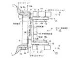
本発明の第1実施形態を図1〜図5に基づいて説明する。本実施形態は、風力発電装置の風車部分で、ブレードを取り付けた軸受をロータヘッドにピッチ角を変更可能に取り付けるためのボルト締結作業に適用される。図1はロータヘッドの側面図、図2は図1中のA―A方向矢視図(正面図)、図3は図1中のC部を拡大して示す説明図、図4はボルトテンショナの作動説明図、図5は図2中のB部拡大図である。(Embodiment 1)
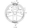
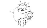
1st Embodiment of this invention is described based on FIGS. The present embodiment is applied to a bolt fastening operation for attaching a bearing attached with a blade to a rotor head so that the pitch angle can be changed in a windmill portion of a wind turbine generator. 1 is a side view of the rotor head, FIG. 2 is a view taken in the direction of arrows AA in FIG. 1 (front view), FIG. 3 is an explanatory view showing an enlarged C portion in FIG. 1, and FIG. FIG. 5 is an enlarged view of a portion B in FIG.
図1において、ロータヘッド1に対してリング状の形状をなす外輪2が植え込みボルト3によって固定される。ロータヘッド1及び外輪2が本実施形態における被締結体である。外輪2には多数のボルト孔2aが全周に亘って穿設され、ボルト孔2aの中心を結ぶ軌跡は円を描く。また、ロータヘッド1にもボルト孔2aに相当する位置に多数のボルト孔1aが全周に亘って穿設されている。 In FIG. 1, an
外輪2の内側にはリング状の形状をなす旋回輪4が挿入され、外輪2と旋回輪4との間には複数のべアリング5が、図5に示すように所定間隔をおいて全周に亘って介装されている。べアリング5によって、旋回輪4は、外輪2に対して、図2に示すように、矢印c方向に回動可能となっている。旋回輪4には、ブレードを取り付けるためにボルト孔4aが全周に亘って穿設され、図1の矢印a方向から図示しないブレードが取り付けられる。該ブレードは外輪2に対して回転可能な旋回輪4によってピッチ角を変更することができる。 A
なお、図2において、べアリング5が省略されていると共に、外輪2に設けられたボルト孔2a、植え込みボルト3及び後述するナット6の一部、及び旋回輪4に穿設されたボルト孔4aの一部が省略されている。 In FIG. 2, the
旋回輪4に本発明に係るボルト締結装置10が取り付けられる。ボルト締結装置10は、外輪2及び旋回輪4の中央に位置すると共にボルト孔2aを結ぶ円軌跡の中心hに位置するように基部11が設けられ、基部11と一体の2本の固定腕12a及び12bが外輪2及び旋回輪4の半径方向に延設されている。固定腕12a及び12bの先端部は、ブレードを取り付けるためのボルト孔4aにボルト13で固定される。 A
図2に示すように、基部11には回転腕14が回転可能に取り付けられている。回転腕14はボルト孔2aを結ぶ円軌跡の直径上に配置され、基部11に設けられた回転駆動装置15によって基部11を中心として回転駆動される。回転駆動装置15は図示しない電動モータと該電動モータの出力を回転腕14に伝達する伝達機構及び減速装置等からなる。回転腕14の両端には夫々ボルトテンショナ20が装着されている。ボルトテンショナ20は、回転腕14の回動によって順々にボルト孔2aに対向可能な位置に配置されている。 As shown in FIG. 2, a
図3に示すように、回転腕14の先端には、回転腕14に対して直角方向にフレーム14aが一体に取り付けられている。フレーム14aには、円筒形の防振ゴム19を介して、フレーム14aと平行にフレーム16が取り付けられている。このため、フレーム16は、フレーム14aに対して揺動可能になっている。フレーム16のボルトテンショナ20に対向する面にはレール16aが固設されている。
ボルトテンショナ20の本体ケース21には、連結部材22が固設され、連結部材22の先端には、レール16aと対面して凹部22aが形成されている。凹部22aがレール16aに嵌合され、連結部材22はレール16a上を矢印b方向に摺動可能に構成されている。As shown in FIG. 3, a
A connecting
本体ケース21の内部には、電動モータ23が設けられ、電動モータ23の出力軸23aは本体ケース21の下方に配置された円筒形状の固定部材24に接続されている。そのため、電動モータ23によって固定部材24を回転することができる。固定部材24と一体となった下部小径部24aには、メネジが形成されたメネジ孔24bが穿設され、メネジ孔24bは植え込みボルト3の頭部に対面する位置に開口している。メネジ孔24bが植え込みボルト3の頭部に形成されたオネジ部3aに螺合することにより、植え込みボルト3に対して固定部材24が固定される。メネジ孔24bの開口部は、傾斜面24cが形成されて、拡径されている。
また、固定部材24は、本体ケース21に対してガタがもうけられている。An
Further, the fixing
固定部材24の下方には、環状のベース25が配置されている。ベース25には連結部材30及びレール16aに嵌合する凹部を有する摺動片21bが一体に固設されている。フレーム16の内部には、エアシリンダ17が収納され、エアシリンダ17のピストンロッド17aが接続部材18を介して摺動片21bに接続されている。これによって、ベース25はエアシリンダ17によって矢印b方向に移動可能になっている。 An
図4に示すように、ベース25の内部には、環状の油圧室25aが穿設され、油圧室25aには環状のピストン環26が油圧室25aの液密状態を保ちながら摺動可能に挿入されている。油圧室25aは、ベース25に形成された圧油路25bを介して圧油管27に接続され、圧油管27は圧油供給タンク28に接続されている。圧油管27には油流量を調整する電磁弁29が介装されている。 As shown in FIG. 4, an annular hydraulic chamber 25a is formed in the
かかる構成により、圧油を油圧室25aに供給することにより、ピストン環26を上方に押し上げ、ピストン環26の上面に当接した固定部材24を上方に押し上げることができる。これによって、固定部材24に固定された植え込みボルト3に引張り力を付与し、植え込みボルト3に上方への伸びを与えることができる。 With this configuration, by supplying the pressure oil to the hydraulic chamber 25a, the
外輪2に穿設されたボルト孔2aには、作業員により予め植え込みボルト3が仮螺合されると共に、植え込みボルト3にナット6が仮螺合されている。そして、ベース25の先端側には環状のブリッジ31が固設され、ブリッジ31が植え込みボルト3及びナット6を囲むように配置される。ボルト締結作業時に、ブリッジ31の下面は外輪2の上面に当接される。 The
ブリッジ31の内部には空間31aが設けられ、空間31aにはナット6を回すための袋ナット39が回動可能に収納されている。ベース25には、袋ナット39を含むナット回転機構32が設けられている。ナット回転機構32は、該袋ナット39と、ベース25に取り付けられた電動モータ33と電動モータ33の出力軸に接続された歯車34とから構成されている。袋ナット39の外周面には歯溝が形成され、歯車34と袋ナット39とが螺合し、歯車34の回転を袋ナット39に伝達する。袋ナット39の内側断面は、六角形をなすナット6の外周と遊嵌する六角形をなしている。 A
連結部材30には丸棒30aがフレーム16に平行に固設されている。丸棒30aは、連結部材22のフレームを貫通し、先端に係止板30bが取り付けられている。そして、連結部材22と係止板30b間で丸棒30aの周囲にコイルバネ38が装着され、コイルバネ38の両端は、係止板30bと連結部材22のフレームに係止している。
かかる構成により、エアシリンダ17により駆動されてベース25が外輪2の上面に接近すると、コイルバネ38の弾性力により本体ケース21もベース25と共に、外輪2に接近し、ベース25が外輪2から離れる方向に移動すると、本体ケース21も外輪2から離れる方向に移動する。ただし、ベース25と本体ケース21間の間隔は可変となる。A
With this configuration, when the
ベース25が外輪2の上面に接近した時、袋ナット39がナット6に当り、そこで一旦停止する。これを検知して、電動モータ33を作動させ、袋ナット39を回す。袋ナット39の内側断面がナット6に嵌合する位置に来た時、ナット6の外側に袋ナット39が入り込んでベース25が外輪2側に進む。そして、ベース25の端面が外輪2の上面に当って、ベース25が停止する。
このとき、コイルバネ38の弾性力により、固定部材24の下部小径部24aは、植え込みボルト3の頭部に押し当てられる。When the base 25 approaches the upper surface of the
At this time, the lower
この状態で、電動モータ23を駆動することにより、下部小径部24aのメネジ孔24bが植え込みボルト3の頭部に螺合する。そして、固定部材24の下面がピストン環26の上面に当った時点で電動モータ23を停止させる。その後、油圧室25aに圧油を注入することにより、固定部材24を上方に押し上げ、植え込みボルト3に引張力を加える。 In this state, by driving the
次に、本実施形態のボルトテンショナ20の位置決め機構40を図5に基づいて説明する。図5において、位置決め機構40は、外輪2に対面する側の回転腕14の端面に装着されている。基部41は、回転腕14に固定されたエアシリンダ42のピストンロッド42aに接続されて、矢印e方向に往復動可能に構成されている。基部41の両脇には一対の位置決めバー43a及び43bが取り付けられている。 Next, the
基部41の内部には図示しない電動モータが収納され、該電動モータの回転が図示しない伝達機構を介して位置決めバー43a及び43bに伝達される。この伝達機構により、位置決めバー43a及び43bは、これらの中間地点gからの両者の距離la及びlbが常に等しくなるように、矢印f方向に往復動可能となっている。中間地点gは、回転腕14の長手方向の中心線上に位置している。 An electric motor (not shown) is accommodated in the
位置決めバー43a及び43bは、回転腕14の一方の先端に取り付けられており、一方、ボルトテンショナ20は回転腕14の両端に取り付けられている。そして、位置決めバー43a及び43bの中間地点gと2個のボルトテンショナ20との位置関係は、回転腕14の回転中心hに対して0°又は180°の相対角度をなすように規定されている。 The positioning bars 43 a and 43 b are attached to one end of the
また、図4において、ベース25にはレーザ計測器35が埋設されており、レーザ計測器35で固定部材24に取り付けられた計測バー36との間隔dを計測することにより、引張り力を付与された植え込みボルト3の伸び量を検知する。 In FIG. 4, a
かかる本実施形態において、図1及び図2に示すようにボルト締結装置10を旋回輪4に固定した状態でボルト締結装置10を作動させる。まず、回転駆動装置15を作動させて回転腕14の両端に装着されたボルトテンショナ20を夫々ボルト孔2aのひとつに対向する位置に位置決めする必要がある。このとき、ボルト孔2aには、作業員によって予め植え込みボルト3が仮螺合され、植え込みボルト3のオネジ部3aにナット6が仮螺合されている。 In this embodiment, the
ボルトテンショナ20の位置決めは、図5に示すように、位置決め機構40から一対の位置決めバー43a及び43bをボルト孔2aに仮螺合された植え込みボルト3に向かって突出させる。例えば、図5中、植え込みボルト3iをボルト締結作業の対象とする場合には、図5に示すように、一対の位置決めバー43a及び43bの中心位置に植え込みボルト3iが置かれるように、位置決めバー43a及び43bを配置し、植え込みボルト3iから等間隔の位置にある両側のボルト間に位置決めバー43a及び43bを挿入する。As shown in FIG. 5, the
次に、位置決めバー43a及び43bを互いに開く方向に移動させて外側の植え込みボルトに当接させる。この動作によって植え込みボルト3iを一対の位置決めバー43a及び43bの中心(中間地点g)に位置させることができる。これで自動的に2個のボルトテンショナ20を植え込みボルト3i及び植え込みボルト3iと180°の相対角度をなす植え込みボルト3に対向して配置させることができる。Next, the positioning bars 43a and 43b are moved in the direction of opening each other and brought into contact with the outer studs. By this operation, the
このようにしてボルトテンショナ20を位置決めした後、2個のボルトテンショナ20を用いて2個の植え込みボルト3の締結作業を同時に行なうことができる。締結作業が終わったら、前記位置決め要領で隣の植え込みボルト3i+1に順々にボルトテンショナ20を位置決めさせればよい。After positioning the
次に、コントローラ37によりエアシリンダ17を作動させて、ボルトテンショナ20の固定部材24を植え込みボルト3iに接近させる。本体ケース21はコイルバネ38の弾性力でベース25と一緒に前進する。そして、袋ナット39の下面がナット6の上面に当ったことを検知して、電動モータ33を作動させ、袋ナット39を回動させる。袋ナット39の内側断面がナット6の外形に合致した位置で、ベース25が前方に進み、袋ナット39の下面が外輪2の上面に当接する。Then, by operating the
この状態で、固定部材24の下部小径部24aのメネジ孔24bの開口は、コイルバネ38の弾性力により植え込みボルト3iの頭部に押し付けられる。本体ケース21を支持するフレーム16は、フレーム14aに防振ゴム19を介して微動可能に支持され、かつ固定部材24は本体ケース21に対してガタをもって取り付けられている。しかも、メネジ孔24bの開口は傾斜面24cをもって拡径されているので、植え込みボルト3の取付け位置に公差(最大3mm)があっても、その公差によるずれを吸収して、植え込みボルト3の頭部をメネジ孔24bに一致させることができる。In this state, the opening of the
そして、電動モータ23を作動させて固定部材24を回転させることにより、メネジ孔24bを植え込みボルト3iの頭部に形成されたオネジ部3aに螺合させ、固定部材24の下面がピストン環26の上面に接した時点で電動モータ23を止める。これによって、固定部材24が植え込みボルト3iに固定される。Then, by rotating the fixing
次に、コントローラ37により電磁弁29を開き、圧油供給タンク28から、圧油管27及び圧油路25bを介して油圧室25aに圧油を供給する。そして、油圧によってピストン環26を植え込みボルト3iから離れる方向に押し上げ、ピストン環26によって固定部材24が押し上げられる。このとき、油圧室25aに供給される圧油流量の調整は、コントローラ37で電磁弁29の開度を制御することにより行なう。
これによって、植え込みボルト3iに軸方向の引張り力を付与し、植え込みボルト3iに軸方向の伸びを与えることができる。Next, the
Thus, by applying a tensile force in the axial direction to the
なお、油圧室25aに供給した圧油の圧力を検知して、植え込みボルト3iに付与した引張り力を検知するとともに、レーザ計測器35によって植え込みボルト3iの伸び量を検知する。該引張力と植え込みボルト3iの伸び量とから、植え込みボルト3iの不良を検知することができる。あるいは、引張力を解除した時のボルトの縮み量から、ボルトの不良を検出してもよい。Note that detects the pressure of pressure oil supplied to the hydraulic chamber 25a, thereby detecting the tensile force imparted to the
植え込みボルト3iに伸びを与えることにより、ナット6の下面と外輪2の表面との間に隙間が生じる。次に、コントローラ37によりナット回転機構32の電動モータ33を作動させ、歯車34を回転させることにより、ナット6を回転させる。これによって、ナット6を植え込みボルト3iにねじ込み、ナット6と外輪2との隙間をなくす。A gap is generated between the lower surface of the
このようにして、植え込みボルト3iのねじ込み作業を終了すると、固定部材24を逆回転させてメネジ部24bと植え込みボルト3iのオネジ部3aとの螺合を外す。メネジ部24bと植え込みボルト3iのオネジ部3aとが外れたら、エアシリンダ17を作動させて、ベース25を外輪2の上面から遠ざける。ベース25を外輪2から遠ざける方向に移動させると、コイルバネ38の弾性力により、本体ケース21も同じ方向に移動する。こうして、ボルトテンショナ20を植え込みボルト3iから引き離す。次に、同じ手順で隣の植え込みボルト3i+1から順々にねじ込み作業を行なう。In this way, when the screwing operation of the
本実施形態によれば、円周上に多数配置された植え込みボルト3の締結作業を略自動化できるので、作業時間を大幅に短縮することができる。しかも、2本の固定腕12a及び12bと1個の回転腕14からなる簡易な装置であるため、安価な設備費でボルトの自動締結が可能となる。
また、円形に配置されたボルトを結ぶ円形の軌跡の直径上に回転腕14を配置し、2個のボルトテンショナ20で同時に締結作業を行なうので、さらに作業時間を短縮することができる。According to this embodiment, since the fastening operation | work of
Further, since the
また、前記位置決め機構40でボルトテンショナ20を各植え込みボルト3に位置決めするようにしているので、電気的なセンサや複雑な制御装置を用いることなしに、簡単な構造の機械的な手段のみで、ボルトテンショナ20を締結対象となるボルト孔に位置決めすることができる。 Further, since the
さらに、本体ケース21を支持するフレーム16は、フレーム14aに防振ゴム19を介して微動可能に支持され、かつ固定部材24は本体ケース21に対してガタをもって取り付けられ、しかも、メネジ孔24bの開口は傾斜面24cをもって拡径されているので、植え込みボルト3の取付け位置に公差があっても、その公差による植え込みボルト3の頭部とメネジ孔24bの開口とのずれを吸収して、植え込みボルト3の頭部をメネジ孔24bに一致させることができる。 Further, the
なお、予め、ボルト孔2aに植え込みボルト3を仮螺合する場合に、固定部材24のメネジ孔24bに植え込みボルト3のオネジ部3aを螺合させておき、この状態で、植え込みボルト3をボルト孔2aに位置決めし、固定部材24を電動モータ23で回転させて、仮螺合させるようにしてもよい。 In addition, when the
(実施形態2)
次に、本発明の第2実施形態を図6に基づいて説明する。図6において、本実施形態のボルト締結装置50は、2本の回転腕51a及び51bを回転中心hを通るように基部11に固定したものである。回転腕51a及び51bは、互いに直交するように配置され、その両端にボルトテンショナ20が装着されている。また、回転腕51a及び51bの両端には、外輪2の端面に接するようにガイドローラ53が装着されている。そして、回転腕51a及び51bの両端付近の内部には、ガイドローラ53を回転駆動する回転駆動装置54が収納されている。(Embodiment 2)
Next, a second embodiment of the present invention will be described with reference to FIG. In FIG. 6, the
その他の構成は前記第1実施形態と同一であり、同一の部材又は機器には前記第1実施形態と同一符号を付している。本実施形態は、4個のボルトテンショナ20で同時にボルト締結作業を行なうので、作業時間を大幅に短縮することができる。しかも、2本の回転腕51a及び51bのみを設けているので、設備費を低く押えることができる。 Other configurations are the same as those of the first embodiment, and the same members or devices are denoted by the same reference numerals as those of the first embodiment. In this embodiment, since the bolt fastening operation is simultaneously performed by the four
さらに、回転腕51a及び51bの両端でガイドローラ53を外輪2の端面に当接させ、ガイドローラ53の回転により回転腕51a及び51bを回転させるようにしているので、回転腕51a及び51bの移動を円滑に行なうことができる。しかも、回転腕51a及び51bを回転駆動する装置54を基部11に設ける代わりに、回転腕51a及び51bの両端付近に設けているので、回転腕51a及び51bの回転動作を確実かつ正確に行なうことができる。 Further, the
(実施形態3)
次に、本発明の第3実施形態を図7及び図8に基づいて説明する。本実施形態は、前記第1又は第2実施形態と同様に、風力発電装置のブレード軸受をロータヘッドに取り付ける際のボルト締結作業である。(Embodiment 3)
Next, a third embodiment of the present invention will be described with reference to FIGS. The present embodiment is a bolt fastening operation when attaching the blade bearing of the wind power generator to the rotor head, as in the first or second embodiment.
図7及び図8において、本実施形態に係るボルト締結装置60は、2個の直線状の回転腕61及び62と、これら回転腕の裏側に配置された固定腕63とから構成されている。回転腕61及び62は、回転軸64を介して相対位置が互いに直交する方向に連結されている。また、回転腕61及び62は、固定腕63に対して、回転軸64を中心に回動可能になっている。回転腕61の一端には、搬送用ブラケット65が固設され、搬送用ブラケット65にはフック66が固着されている。 7 and 8, the
回転腕61の他端には、前記第1実施形態と同一構成の位置決め機構40が取り付けられ、回転腕62の両端には、夫々第1実施形態と同一構成のボルトテンショナ20が取り付けられている。ボルト締結装置60は、回転腕61、62及び固定腕63が一体に連結されたまま、フック66に図示しないクレーンのフックを掛けて吊り下げられる。そして、旋回輪4に穿設されたボルト孔4aにボルト13によって固定腕63の両端を固定する。 A
ボルト締結装置60を旋回輪4に固定した後、ボルト締結作業を行なう。即ち、回転腕61及び62を回転させ、位置決め機構40によって、ボルトテンショナ20を締結対象となる植込みボルト3に対向した位置に位置決めする。そして、外輪2に設けられたボルト孔に仮螺合した植込みボルト3に対してボルトテンショナ20によって順々に引張り力を付与し、植込みボルト3に伸びを与えた後、ナット6をねじ込む。 After the
位置決め機構40が取り付けられた回転腕61と、ボルトテンショナ20が取り付けられた回転腕62の両端とは、回転中心hに対して相対角度を90°に規定されているので、位置決め機構40の位置決めバー43a及び43bを植込みボルト3間で位置決めすることにより、ボルトテンショナ20をボルト締結位置へ位置決めすることができる。 Since the
回転腕61及び62は固定腕63に対して回転可能であり、位置決め機構40を隣りの植込みボルト3に順々に位置決めしていくことによって、植込みボルト3の締結を順々に行なうことができる。回転腕61にはカウンタウエイト67が取り付けられているので、回転腕61及び62の回転を円滑に行なうことができ、ボルトテンショナ20の位置決めが容易になる。 The
本実施形態によれば、ボルト締結装置60は、回転腕14の両端に設けられた2個のボルトテンショナ20で同時にボルト締結作業を行なうことができるので、作業時間を短縮できる。また、直線形状の回転腕61,62及び固定腕63を組み合わせた簡素な構成のボルト締結装置60を用いているので、イニシャルコストを低減でき、組立てが容易である。また、回転腕61に取り付けられたフック66を介して吊り下げることにより、ボルト締結装置60の旋回輪4への固定が容易になる。 According to the present embodiment, the
また、回転腕61の両端に設けられたボルトテンショナ20と、回転腕62の先端に設けられた位置決め機構40とは、位置決め機構40を真ん中に配置して互いに90度ずつ位相をずらせた位置関係にあるので、位置決め機構40による位置決めとボルトテンショナ20によるボルト締結とを同時に並行して行なうことができ、作業時間を短縮できる。 Further, the
(実施形態4)
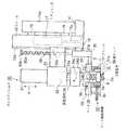
次に、本発明の第4実施形態を図9及び図10に基づいて説明する。本実施形態は、前記第1実施形態と風力発電装置の同一対象部分のボルト締結作業に適用されたものである。図9において、前記第1実施形態の図3と同一の部材又は機器には、図3と同一符号を付しており、これら同一部分の説明を省略する。本実施形態では、ボルトテンショナ20及びベース25を支持するフレーム16を支持機構70を介して回転腕14に取り付けている。その他の構成は第1実施形態と同一である。以下、支持機構70の構成を説明する。(Embodiment 4)
Next, a fourth embodiment of the present invention will be described with reference to FIGS. This embodiment is applied to the bolt fastening operation of the same target part of the wind turbine generator according to the first embodiment. 9, the same members or devices as those in FIG. 3 of the first embodiment are denoted by the same reference numerals as those in FIG. 3, and description of these same parts is omitted. In the present embodiment, the
ボルトテンショナ20及びフレーム16を取り囲むように一対のリング71が互いに同心に配置され、リング71間には連結部材72が架設され、連結部材72により2個のリング71を結合している。ボルトテンショナ20を支持するフレーム16は、円筒形の防振ゴム19を介して連結部材72に接続され、フレーム16は連結部材72に対して微動可能に支持されている。フレーム16が接続された位置の連結部材72の背面には錘73が固設されている。 A pair of
リング71の周囲に2枚の支持板74が配置されている。支持板74は、外形が略正方形をなし、中心部にリング71の内径と同じような大きさの円形の空隙を有し、該空隙にボルトテンショナ20及びフレーム16が挿入されている。支持板74は、支持板74に固設された接続板75を介して回転腕14に接続されている。
2枚の支持板74の内側には、ボルトテンショナ20の周方向を4等分する4箇所の位置に、ローラ76が回動可能に設けられ、該ローラ76でリング71を回動可能に支持している。Two
Inside the two
なお、本実施形態においても、第1実施形態と同様に、植え込みボルト3の取付け公差に対する対策として、ボルトテンショナ20の固定部材24は、本体ケース21に対してガタをもたせて取り付けてあり、かつ下部小径部24aのメネジ孔24bの開口には傾斜面24cをもうけて拡径してある。 In the present embodiment, as in the first embodiment, the fixing
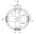
旋回輪4は上下方向に配置されており、ボルトテンショナ20は水平方向に配置されて、ボルト締結作業を行なう。そのため、図10に示すように、ボルトテンショナ20は、垂直面上の円軌跡jに沿って移動する。本実施形態では、ボルトテンショナ20を支持するリング71は、ローラ76によって回動可能に支持されているため、回転腕14がどのような位置にあっても、錘73が常に防振ゴム19の下側に位置する向きになる。そのため、防振ゴム19には常に圧縮荷重kが加わり、引張力やせん断力は作用しない。 The
なお、錘73が防振ゴム19の下側に位置している状態で、ボルトテンショナ20の左右方向に加わる力が均等になるように、ボルトテンショナ20の左右方向の重量バランスを調整してある。 Note that the weight balance in the left-right direction of the
旋回輪4の植え込みボルト3の位置によって、防振ゴム19に圧縮力、引張力又はせん断力等の異なる荷重が加わると、防振ゴム19の支持形状が変わり、この場合、植え込みボルト3の組立て公差を吸収できないおそれがある。
これに対して、本実施形態では、防振ゴム19には常に圧縮荷重kのみが加わるので、防振ゴム19の支持形状は常に一定である。When different loads such as compressive force, tensile force or shearing force are applied to the
On the other hand, in this embodiment, since only the compression load k is always applied to the
そのため、植え込みボルト3に取付け公差がある場合でも、本実施形態では、前記の対策との相乗効果により、メネジ孔24bを植え込みボルト3の頭部に確実に合致させ、確実にボルト締結作業を実施できる。 Therefore, even if there is a mounting tolerance in the
本発明によれば、円弧状又は円形に配置された多数のボルトをボルトテンショナを用いて引張り力を与えながら締結する際に、締結作業を自動化にして、低コストかつ短時間で締結作業を行なうことができる。 According to the present invention, when a large number of bolts arranged in an arc shape or a circle are fastened using a bolt tensioner while applying a tensile force, the fastening operation is automated, and the fastening operation is performed at low cost and in a short time. be able to.
1 ロータヘッド(被締結体)
1a、2a ボルト孔
2 外輪(被締結体)
3 植え込みボルト
6 ナット
6a オネジ部
10、50,60 ボルト締結装置
12a、12b、63 固定腕
14、51a、51b、61,62 回転腕
15、54 回転駆動装置
17 エアシリンダ
19 防振ゴム(弾性体)
24 固定部材(ボルトテンショナ固定手段)
24b メネジ孔
24c 傾斜面
26 ピストン環(荷重付加手段)
35 レーザ計測器(ボルト伸び量計測手段)
40 位置決め機構
43a、43b 一対の位置決めバー
53 ガイドローラ
71 リング(リング状支持部材)
73 錘
h 回転中心
k 圧縮荷重1 Rotor head (fastened body)
1a,
3
24 fixing member (bolt tensioner fixing means)
24b
35 Laser measuring instrument (Bolt elongation measuring means)
40
73 Weight h Center of rotation k Compression load
Claims (9)
Translated fromJapanese複数のボルトを結ぶ円弧の中心を回転中心とするように被締結体に対して回転可能に配置された腕及び該腕を回転駆動する手段と、
該腕に前記ボルト孔に対向可能な位置に設けられ、ボルト孔に仮螺合されたボルトに係止固定される固定部、及びボルトに固定された固定部にボルトから離れる方向に荷重を付加する手段を備えたボルトテンショナと、
ボルトテンショナをボルトに接近させ該固定部をボルトに固定させる手段と、
ボルトテンショナを各ボルト孔に対向する位置に位置決めする手段と、を備え、
該ボルト孔に仮螺合したボルトにボルトテンショナで軸方向の引張り力を付与してボルトに伸びを与え、伸長したボルトをボルト孔にさらにねじ込むか、又は該ボルトに仮螺合されたナットをさらにねじ込むことにより締付力を得るようにし、
前記腕を回転させて該ボルトテンショナにより複数のボルト孔に順々にボルトを螺着させるように構成し、
前記位置決め手段を、前記回転中心に対して前記腕から相対角度を規制されて設けられ、該相対角度上の点から互いに接近又は離反可能でかつボルト締結位置に進退可能に設けられた一対の位置決めバーで構成し、
該位置決めバーをボルト孔に螺着されたボルトの間に挿入しボルト側面に当接することにより、ボルトテンショナを締結対象となるボルト孔に位置決めするように構成したことを特徴とするボルト締結装置。In a bolt fastening device in which a bolt is screwed in a state where an axial tensile force is applied to a plurality of bolt holes arranged in an arc shape in a body to be fastened,
An arm rotatably arranged with respect to the fastened body so that the center of an arc connecting a plurality of bolts is the center of rotation, and a means for rotationally driving the arm;
A load is applied to the arm at a position that can be opposed to the bolt hole, and fixed to the bolt that is temporarily screwed into the bolt hole, and to the fixed part that is fixed to the bolt in a direction away from the bolt. A bolt tensioner with means to
Means for causing the bolt tensioner to approach the bolt and fixing the fixing portion to the bolt;
Means for positioning the bolt tensioner at a position facing each bolt hole,
A bolt tensioner is used to apply an axial tensile force to the bolt that is temporarily screwed into the bolt hole to elongate the bolt, and the extended bolt is further screwed into the bolt hole, or a nut that is temporarily screwed into the bolt is attached. Further tightening force is obtained by screwing,
The arm is rotated, and the bolt tensioner is configured to screw the bolts sequentially into a plurality of bolt holes,
A pair of positioning means, wherein the positioning means is provided with a relative angle restricted from the arm with respect to the center of rotation, and can be moved toward or away from each other from a point on the relative angle and can be moved back and forth to a bolt fastening position. Composed of bars,
A bolt fastening deviceconfigured to position the bolt tensioner in a bolt hole to be fastened by inserting the positioning bar between bolts screwed into the bolt hole and contacting the bolt side surface. .
複数のボルトを結ぶ円弧の中心を回転中心とするように被締結体に対して回転可能に配置された腕及び該腕を回転駆動する手段と、
該腕に前記ボルト孔に対向可能な位置に設けられ、ボルト孔に仮螺合されたボルトに係止固定される固定部、及びボルトに固定された固定部にボルトから離れる方向に荷重を付加する手段を備えたボルトテンショナと、
ボルトテンショナをボルトに接近させ該固定部をボルトに固定させる手段と、
ボルトテンショナを各ボルト孔に対向する位置に位置決めする手段と、を備え、
該ボルト孔に仮螺合したボルトにボルトテンショナで軸方向の引張り力を付与してボルトに伸びを与え、伸長したボルトをボルト孔にさらにねじ込むか、又は該ボルトに仮螺合されたナットをさらにねじ込むことにより締付力を得るようにし、
前記腕を回転させて該ボルトテンショナにより複数のボルト孔に順々にボルトを螺着させるように構成し、
前記腕の回転駆動手段を、該腕に装着され被締結体に当接してガイドされるガイドローラと、該ガイドローラの回転駆動装置で構成したことを特徴とするボルト締結装置。In a bolt fastening device in which a bolt is screwed in a state where an axial tensile force is applied to a plurality of bolt holes arranged in an arc shape in a body to be fastened,
An arm rotatably arranged with respect to the fastened body so that the center of an arc connecting a plurality of bolts is the center of rotation, and a means for rotationally driving the arm;
A load is applied to the arm at a position that can be opposed to the bolt hole, and fixed to the bolt that is temporarily screwed into the bolt hole, and to the fixed part that is fixed to the bolt in a direction away from the bolt. A bolt tensioner with means to
Means for causing the bolt tensioner to approach the bolt and fixing the fixing portion to the bolt;
Means for positioning the bolt tensioner at a position facing each bolt hole,
A bolt tensioner is used to apply an axial tensile force to the bolt that is temporarily screwed into the bolt hole to elongate the bolt, and the extended bolt is further screwed into the bolt hole, or a nut that is temporarily screwed into the bolt is attached. Further tightening force is obtained by screwing,
The arm is rotated, and the bolt tensioner is configured to screw the bolts sequentially into a plurality of bolt holes,
A bolt fastening device,wherein the rotation driving means of the arm comprises a guide roller that is attached to the arm and guided by contact with a body to be fastened, and a rotation driving device of the guide roller .
複数のボルトを結ぶ円弧の中心を回転中心とするように被締結体に対して回転可能に配置された腕及び該腕を回転駆動する手段と、
該腕に前記ボルト孔に対向可能な位置に設けられ、ボルト孔に仮螺合されたボルトに係止固定される固定部、及びボルトに固定された固定部にボルトから離れる方向に荷重を付加する手段を備えたボルトテンショナと、
ボルトテンショナをボルトに接近させ該固定部をボルトに固定させる手段と、
ボルトテンショナを各ボルト孔に対向する位置に位置決めする手段と、を備え、
該ボルト孔に仮螺合したボルトにボルトテンショナで軸方向の引張り力を付与してボルトに伸びを与え、伸長したボルトをボルト孔にさらにねじ込むか、又は該ボルトに仮螺合されたナットをさらにねじ込むことにより締付力を得るようにし、
前記腕を回転させて該ボルトテンショナにより複数のボルト孔に順々にボルトを螺着させるように構成し、
前記腕にリング状支持部材を回動可能に設けると共に、該リング状支持部材の内側に前記ボルトテンショナを弾性体を介して微動可能に設け、
リング状支持部材に錘を取り付け、腕の任意の姿勢に対して該錘を常にリング状支持部材の下方領域に位置させることにより、該弾性体に対してリング状支持部材の荷重が常に同じ方向に加わるように構成したことを特徴とするボルト締結装置。In a bolt fastening device in which a bolt is screwed in a state where an axial tensile force is applied to a plurality of bolt holes arranged in an arc shape in a body to be fastened,
An arm rotatably arranged with respect to the fastened body so that the center of an arc connecting a plurality of bolts is the center of rotation, and a means for rotationally driving the arm;
A load is applied to the arm at a position that can be opposed to the bolt hole, and fixed to the bolt that is temporarily screwed into the bolt hole, and to the fixed part that is fixed to the bolt in a direction away from the bolt. A bolt tensioner with means to
Means for causing the bolt tensioner to approach the bolt and fixing the fixing portion to the bolt;
Means for positioning the bolt tensioner at a position facing each bolt hole,
A bolt tensioner is used to apply an axial tensile force to the bolt that is temporarily screwed into the bolt hole to elongate the bolt, and the extended bolt is further screwed into the bolt hole, or a nut that is temporarily screwed into the bolt is attached. Further tightening force is obtained by screwing,
The arm is rotated, and the bolt tensioner is configured to screw the bolts sequentially into a plurality of bolt holes,
A ring-shaped support member is rotatably provided on the arm, and the bolt tensioner is provided on the inner side of the ring-shaped support member so as to be slightly movable via an elastic body.
By attaching a weight to the ring-shaped support member and always positioning the weight in the lower region of the ring-shaped support member for any posture of the arm, the load of the ring-shaped support member is always in the same direction with respect to the elastic body A bolt fastening device characterized in that the bolt fastening deviceis configured to beadded to the bolt.
該オネジ部とメネジ部とを螺合させることにより、該固定部を植え込みボルトに固定させるように構成したことを特徴とする請求項4に記載のボルト締結装置。The bolt is a planting bolt, and the fixing portion includes a female screw portion that is screwed into a male screw portion formed on a head portion of the planting bolt,
The bolt fastening device according to claim4 , wherein the fixing portion is fixed to the implanted bolt by screwing the male screw portion and the female screw portion.
Priority Applications (1)
| Application Number | Priority Date | Filing Date | Title |
|---|---|---|---|
| JP2008284128AJP5281366B2 (en) | 2008-11-05 | 2008-11-05 | Bolt fastening device |
Applications Claiming Priority (1)
| Application Number | Priority Date | Filing Date | Title |
|---|---|---|---|
| JP2008284128AJP5281366B2 (en) | 2008-11-05 | 2008-11-05 | Bolt fastening device |
Publications (2)
| Publication Number | Publication Date |
|---|---|
| JP2010112422A JP2010112422A (en) | 2010-05-20 |
| JP5281366B2true JP5281366B2 (en) | 2013-09-04 |
Family
ID=42301127
Family Applications (1)
| Application Number | Title | Priority Date | Filing Date |
|---|---|---|---|
| JP2008284128AExpired - Fee RelatedJP5281366B2 (en) | 2008-11-05 | 2008-11-05 | Bolt fastening device |
Country Status (1)
| Country | Link |
|---|---|
| JP (1) | JP5281366B2 (en) |
Families Citing this family (10)
| Publication number | Priority date | Publication date | Assignee | Title |
|---|---|---|---|---|
| KR101194576B1 (en)* | 2010-12-16 | 2012-10-25 | 삼성중공업 주식회사 | Wind turbine assembly and management robot and wind turbine including the same |
| JP5653780B2 (en)* | 2011-02-01 | 2015-01-14 | 三菱重工業株式会社 | Fastening and loosening device |
| DE102016205400A1 (en)* | 2016-03-31 | 2017-10-05 | Man Diesel & Turbo Se | Device for positioning a holding device for a screw connection in overhead mounting and dismounting |
| KR102227072B1 (en)* | 2016-11-23 | 2021-03-12 | 주식회사 기가레인 | Apparatus for fastening screw of probe card and apparatus for assembling probe card comprising the same |
| WO2018097446A1 (en)* | 2016-11-23 | 2018-05-31 | 주식회사 기가레인 | Screw fastening device for probe card and probe card assembling device having same |
| JP7035363B2 (en)* | 2017-08-02 | 2022-03-15 | 日本電気株式会社 | Input / output circuit characteristic adjustment device and input / output circuit characteristic adjustment method |
| DE102018107657A1 (en)* | 2018-03-29 | 2019-10-02 | Frank Hohmann | Device for tightening screw connections |
| CN112091589B (en)* | 2020-09-18 | 2022-07-01 | 一重集团大连核电石化有限公司 | Fastening method of large-diameter dense bolt |
| CN112975365B (en)* | 2021-02-26 | 2022-02-18 | 厦门馨天达金属制造有限公司 | Automatic bolt locking equipment for iron frame bed |
| CN113182836B (en)* | 2021-06-08 | 2024-06-21 | 中联重科股份有限公司 | Automatic tightening device for connecting bolts of slewing bearing and turntable |
Family Cites Families (7)
| Publication number | Priority date | Publication date | Assignee | Title |
|---|---|---|---|---|
| JPS618282A (en)* | 1984-06-23 | 1986-01-14 | バブコツク日立株式会社 | Bolt screwing and unscrewing device |
| JPH02156488A (en)* | 1988-12-08 | 1990-06-15 | Hitachi Ltd | Magnetic head manufacturing method and device |
| JPH03103610A (en)* | 1989-09-18 | 1991-04-30 | Toshiba Corp | Apparatus for tightening axial force bolt |
| JP3360263B2 (en)* | 1995-07-18 | 2002-12-24 | 三菱電機株式会社 | Screw fastening device |
| JPH11223693A (en)* | 1998-02-04 | 1999-08-17 | Ishikawajima Harima Heavy Ind Co Ltd | Nut member attachment / detachment transfer device |
| JP2000071133A (en)* | 1998-08-28 | 2000-03-07 | Babcock Hitachi Kk | Bolt dismounting-mounting device and its method |
| FR2905460B1 (en)* | 2006-09-01 | 2009-08-07 | Skf Ab | METHOD AND DEVICE FOR CONTROLLING HYDRAULIC CLAMPING OF ONE OR MORE BOLTS. |
- 2008
- 2008-11-05JPJP2008284128Apatent/JP5281366B2/ennot_activeExpired - Fee Related
Also Published As
| Publication number | Publication date |
|---|---|
| JP2010112422A (en) | 2010-05-20 |
Similar Documents
| Publication | Publication Date | Title |
|---|---|---|
| JP5281366B2 (en) | Bolt fastening device | |
| EP2199605B1 (en) | Method and assembly for mounting rotor blade bearings of a wind turbine | |
| KR101958676B1 (en) | Bolt tightening robot for wind turbines | |
| CN102114632B (en) | Rope-driven parallel robot capable of realizing rapid reconfiguration | |
| CN107538210B (en) | Bolt tightening device and its operation method | |
| JP5592854B2 (en) | Fastening device | |
| CA3011911A1 (en) | Robot with positioning means to move a tool along a flange connection | |
| RU2734663C2 (en) | Machine for screwing and unfastening bolts of sleepers | |
| US20090179428A1 (en) | Shaft for use in a wind energy system and wind energy system | |
| CN107717817B (en) | Control system for bolt fastening device | |
| CN103293071A (en) | Tension-torsion combined fatigue testing device | |
| JP2007107955A (en) | Torsional fatigue testing machine | |
| JP5295348B2 (en) | Linear actuator and mechanical testing machine | |
| CN115122081B (en) | Tightening device | |
| CN108406289B (en) | Moment loading device | |
| CN102174945B (en) | Mechanical driving device with output displacement and torsion | |
| CN109605284B (en) | Bolt pre-tightening stretching device and method | |
| JP5146392B2 (en) | Bolt supply device for nutrunner | |
| CN107525722B (en) | Bolt bending fatigue test tool, test device and test method | |
| CN221054554U (en) | Auxiliary pipe feeding device for pipeline detection robot | |
| CN222836401U (en) | Connector docking apparatus and nut mounting assembly | |
| CN223049576U (en) | Connector docking apparatus and flange docking system | |
| CN119715209A (en) | Heavy-duty wirerope drawing machine | |
| WO2012018396A1 (en) | Fastener tensioning device and method | |
| JP5820182B2 (en) | Cylinder device |
Legal Events
| Date | Code | Title | Description |
|---|---|---|---|
| A621 | Written request for application examination | Free format text:JAPANESE INTERMEDIATE CODE: A621 Effective date:20110701 | |
| A131 | Notification of reasons for refusal | Free format text:JAPANESE INTERMEDIATE CODE: A131 Effective date:20121009 | |
| RD02 | Notification of acceptance of power of attorney | Free format text:JAPANESE INTERMEDIATE CODE: A7422 Effective date:20121023 | |
| A521 | Written amendment | Free format text:JAPANESE INTERMEDIATE CODE: A523 Effective date:20121210 | |
| TRDD | Decision of grant or rejection written | ||
| A01 | Written decision to grant a patent or to grant a registration (utility model) | Free format text:JAPANESE INTERMEDIATE CODE: A01 Effective date:20130430 | |
| A61 | First payment of annual fees (during grant procedure) | Free format text:JAPANESE INTERMEDIATE CODE: A61 Effective date:20130524 | |
| R150 | Certificate of patent or registration of utility model | Free format text:JAPANESE INTERMEDIATE CODE: R150 | |
| LAPS | Cancellation because of no payment of annual fees |