Movatterモバイル変換


[0]ホーム

URL:


JP5280767B2 - Repetitive clip treatment tool - Google Patents

Repetitive clip treatment tool
Download PDF

Info

Publication number
JP5280767B2
JP5280767B2JP2008208944AJP2008208944AJP5280767B2JP 5280767 B2JP5280767 B2JP 5280767B2JP 2008208944 AJP2008208944 AJP 2008208944AJP 2008208944 AJP2008208944 AJP 2008208944AJP 5280767 B2JP5280767 B2JP 5280767B2
Authority
JP
Japan
Prior art keywords
clip
sheath
operation wire
wire
clips
Prior art date
Legal status (The legal status is an assumption and is not a legal conclusion. Google has not performed a legal analysis and makes no representation as to the accuracy of the status listed.)
Expired - Fee Related
Application number
JP2008208944A
Other languages
Japanese (ja)
Other versions
JP2010042161A (en
Inventor
孝之 飯田
勝福 崔
Current Assignee (The listed assignees may be inaccurate. Google has not performed a legal analysis and makes no representation or warranty as to the accuracy of the list.)
Fujifilm Corp
Original Assignee
Fujifilm Corp
Priority date (The priority date is an assumption and is not a legal conclusion. Google has not performed a legal analysis and makes no representation as to the accuracy of the date listed.)
Filing date
Publication date
Application filed by Fujifilm CorpfiledCriticalFujifilm Corp
Priority to JP2008208944ApriorityCriticalpatent/JP5280767B2/en
Publication of JP2010042161ApublicationCriticalpatent/JP2010042161A/en
Application grantedgrantedCritical
Publication of JP5280767B2publicationCriticalpatent/JP5280767B2/en
Expired - Fee Relatedlegal-statusCriticalCurrent
Anticipated expirationlegal-statusCritical

Links

Images

Landscapes

Abstract

<P>PROBLEM TO BE SOLVED: To provide a multishot type clipping treatment instrument which enhances operability and accuracy by transmitting a moving amount of an operational wire at an operational part at a proximal end of a sheath to a distal end portion of the operational wire at a distal end portion of the long sheath more accurately and by accurately preparing a subsequent clip after the use of a previous clip. <P>SOLUTION: The multishot type clipping treatment instrument is equipped with a row of clips comprising a plurality of coupled clips and a connecting member, the sheath loaded with the row of clips, the operational wire which is movably disposed in the sheath and has the distal end detachably connected to the connecting member to pull the row of clips, and the operational part which is provided on the proximal end side of the sheath to operate the operational wire in a manner to advance and retreat relative to the sheath. The sheath includes a first part which is located at the distal end side and is loaded with the row of the clips and a second part which is located at the proximal end side and is thinner than the first part to insert the operational wire coaxially in a manner to pull the operational wire. <P>COPYRIGHT: (C)2010,JPO&amp;INPIT

Description

Translated fromJapanese

本発明は、生体内等において止血や傷口の縫合や閉塞等に用いられる内視鏡用クリップ処置具に関し、特に、複数のクリップを連発して使用できる連発式クリップ処置具に関する。  The present invention relates to an endoscopic clip treatment tool used for hemostasis, wound closure, occlusion, and the like in a living body, and more particularly to a repetitive clip treatment tool that can be used in a repetitive manner.

近年、内視鏡用クリップ処置具は、生体内に挿入した内視鏡の先端からクリップを突出させて、出血部や病変組織除去後の処置部をクリップで摘み、止血や傷口の縫合や閉塞を行うために用いられている。  In recent years, an endoscopic clip treatment tool has been used to project a clip from the distal end of an endoscope inserted into a living body, pick a treatment portion after removal of a bleeding part or a lesion tissue with a clip, and stop or stop a hemostasis or wound. Is used to do.

例えば、クリップ処置具として、特許文献1には、コイルからなる可撓性のリング支持管を樹脂チューブ製のシース内に軸線方向に相対的に進退可能に内挿し、シースとリング支持管との間に湾曲操作ワイヤを挿通配置すると共に、リング支持管内にクリップ操作ワイヤを挿通し、クリップ操作ワイヤの先端に連結部材を介して1個のクリップを係脱可能に係合させた内視鏡用クリップ装置が開示されている。特許文献1では、樹脂チューブ製のシースと、コイルパイプからなる可撓性のリング支持管とを相対的に進退可能に別体として形成し、リング支持管およびシース等の先端近傍部分を任意に湾曲させるようにし、内視鏡が斜め方向からしか接近できない患部等を正面から容易にクリップし、確実な止血処置等を行うことができるようにしている。  For example, as a clip treatment tool, Patent Document 1 discloses that a flexible ring support tube made of a coil is inserted into a sheath made of a resin tube so as to be relatively movable in the axial direction, and between the sheath and the ring support tube. For an endoscope in which a bending operation wire is inserted and arranged between them, a clip operation wire is inserted into the ring support tube, and one clip is removably engaged with the tip of the clip operation wire via a connecting member. A clip device is disclosed. In Patent Document 1, a sheath made of a resin tube and a flexible ring support tube made of a coil pipe are formed as separate bodies so as to be able to move forward and backward relative to each other. It is made to curve, and the affected part etc. which an endoscope can approach only from an oblique direction are easily clipped from the front, and a reliable hemostasis treatment etc. can be performed.

また、特許文献2には、前のクリップの後端部分に形成された連結孔に、後ろのクリップの先端爪部を係合させることにより、複数のクリップが90度ずつ交互に向きを変えて直接連結して、連結した複数のクリップの後端を連結部材を介して操作ワイヤの先端に係脱可能に係合させ、連結した複数のクリップをシース先端内に配置すると共に、複数のクリップが係合される操作ワイヤをシース内に軸線方向に進退自在に配置するようにした内視鏡用クリップ装置が開示されている。特許文献2では、シースは、コイルパイプに樹脂チューブを外装して形成されている。  Further, inPatent Document 2, a plurality of clips are alternately turned 90 degrees by engaging the front end claw portion of the rear clip with a connecting hole formed in the rear end portion of the front clip. Directly connected, the rear ends of the connected clips are releasably engaged with the distal end of the operation wire via the connecting member, and the connected clips are arranged in the sheath distal end. An endoscope clip device is disclosed in which an operating wire to be engaged is disposed in a sheath so as to be movable back and forth in the axial direction. InPatent Document 2, the sheath is formed by covering a coil pipe with a resin tube.

また、特許文献3には、湾曲した内視鏡のチャネル内でコイル状の管状体に強い圧縮力が印加された場合においても、コイル素線がズレて管状体が塑性変形してしまうのを抑えることができる、ばね定数の異なる第一コイルと第二コイルを同軸上に接続する内視鏡用処置具が提案されている。  Further, Patent Document 3 discloses that even when a strong compressive force is applied to a coiled tubular body in a curved endoscope channel, the coil wire is displaced and the tubular body is plastically deformed. An endoscopic treatment tool that connects a first coil and a second coil having different spring constants on the same axis, which can be suppressed, has been proposed.

特開2003−608号公報Japanese Patent Laid-Open No. 2003-608特開2006−187391号公報JP 2006-187391 A特開2008−36003号公報JP 2008-36003 A

特許文献1に開示された内視鏡用クリップ装置のような従来の内視鏡用クリップ処置具は、シースやリング支持管の内径に比べ操作ワイヤが細いことから、シースやリング支持管と操作ワイヤとの間に比較的大きな空間が存在し、使用時に湾曲させると、当該空間によりシースやリング支持管と操作ワイヤの経路長に差が発生する。  The conventional endoscopic clip treatment tool such as the endoscopic clip device disclosed in Patent Document 1 has an operation wire thinner than the inner diameter of the sheath or ring support tube. If a relatively large space exists between the wire and the wire is bent during use, a difference occurs in the path length of the sheath or ring support tube and the operation wire due to the space.

ここで、従来の内視鏡用クリップ処置具におけるシースやリング支持管と操作ワイヤの経路長の差の発生要因について検討する。以下では、特許文献1や2と異なり、コイルパイプ自体がシースを構成するものとして説明する。
まず、図16(A)に模式的に示すように、シース108が直線状態であるときに、シース108を構成するコイル102は、コイル102の軸線方向の断面において、コイル102を構成する線材102a間の間隔は等間隔となっている。このとき、図16(A)に示すコイル102の軸線方向の断面において、コイル102の中心線の上側の部分と下側の部分の軸線方向の長さは等しくなり、この長さは湾曲していないシース108の中心104の軸線方向の長さとも等しくなるので、シース108の両端(図示省略)の中心間の距離を直線時の実効距離と呼ぶ。
Here, the cause of the difference in path length between the sheath or ring support tube and the operation wire in the conventional endoscopic clip treatment tool will be examined. Below, unlikepatent documents 1 and 2, it explains as what a coil pipe itself constitutes a sheath.
First, as schematically shown in FIG. 16A, when thesheath 108 is in a linear state, thecoil 102 constituting thesheath 108 has awire rod 102a constituting thecoil 102 in the axial cross section of thecoil 102. The interval between them is equal. At this time, in the cross section in the axial direction of thecoil 102 shown in FIG. 16A, the length in the axial direction of the upper portion and the lower portion of the center line of thecoil 102 is equal, and this length is curved. Since the length in the axial direction of thecenter 104 of the non-sheath 108 is equal, the distance between the centers of both ends (not shown) of thesheath 108 is referred to as an effective distance in a straight line.

次に、シース108を湾曲させた場合には、図16(B)に模式的に示すように、コイル102の湾曲の内周側の部分はB方向に縮み、湾曲の外周側の部分はA方向に伸びる。ここで、B方向の縮む長さとA方向の伸びる長さは、B方向の縮み代が少ないため均等とはならない。従って、湾曲時のシース108の一端から他端まで(図示省略)のシース中心106の軸線に沿った長さを湾曲時の実効距離とすると、湾曲時の実効距離は、湾曲の外周側の部分の伸びに応じて、すなわち、曲率半径が小さい湾曲であるほど、直線時の実効距離よりも長くなる。  Next, when thesheath 108 is curved, as schematically shown in FIG. 16B, the inner peripheral side portion of thecoil 102 is contracted in the B direction, and the outer peripheral side portion of the curve is A. Extend in the direction. Here, the contraction length in the B direction and the extension length in the A direction are not equal because the contraction allowance in the B direction is small. Therefore, when the length along the axis of thesheath center 106 from one end to the other end (not shown) of thesheath 108 at the time of bending is defined as the effective distance at the time of bending, the effective distance at the time of bending is a portion on the outer peripheral side of the curve. In other words, the smaller the curvature radius, the longer the effective distance in a straight line.

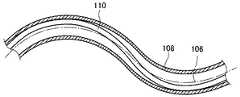
次に、図17に示すクリップ処置具において、湾曲した状態のシース108と操作ワイヤ110の関係を示す。操作ワイヤ110は、その先端に取り付けられたクリップ(図示せず)を前後に動かすためにシース108内を前後に動くが、操作ワイヤ110には、その進退動作によって座屈しないだけの剛性が必要である。そうすると、湾曲部において操作ワイヤ110は、自身の曲げ剛性によって直線状になろうとする力が働くため、シース108内の湾曲部の外周側、すなわち最も長い経路をたどることとなる。これにより、操作ワイヤ110のたどる経路は、シース108の一端から他端まで(図示省略)の湾曲しているシース中心106の軸線に沿った長さである湾曲時の実効距離よりも長い経路となる。  Next, in the clip treatment tool shown in FIG. 17, the relationship between thesheath 108 and theoperation wire 110 in a curved state is shown. Theoperation wire 110 moves back and forth in thesheath 108 in order to move a clip (not shown) attached to the tip of theoperation wire 110 back and forth. However, theoperation wire 110 needs to be rigid enough not to buckle due to its forward / backward movement. It is. Then, theoperation wire 110 in the bending portion is subjected to a force that tends to be linear due to its bending rigidity, and therefore follows the outer peripheral side of the bending portion in thesheath 108, that is, the longest path. Thereby, the path followed by theoperation wire 110 is a path longer than the effective distance at the time of bending, which is the length along the axis of thecurved sheath center 106 from one end of thesheath 108 to the other end (not shown). Become.

図17に示すように、操作ワイヤ110が最長経路をたどった場合には、手元の操作部(図示せず)で操作ワイヤ110を進退操作したとしても、操作ワイヤ110の進退動作以外にも、湾曲部においてシース108の外周側に沿っている操作ワイヤ110が、シース中心106へ近づく方向へ動くなどの動きによって、シース中心106に沿って算出されるシース108の実行距離と、操作ワイヤ110の実行距離とにずれが生じ、操作部でのシース108に対する操作ワイヤ110の移動量と、シース108の先端部でのシース108に対する操作ワイヤ110の移動量が一致しなくなる。  As shown in FIG. 17, when theoperation wire 110 has taken the longest path, even if theoperation wire 110 is advanced / retreated by the operation unit (not shown) at hand, The operation distance of thesheath 108 calculated along thesheath center 106 by the movement such as theoperation wire 110 along the outer peripheral side of thesheath 108 moving toward thesheath center 106 in the bending portion, and theoperation wire 110 There is a deviation from the execution distance, and the amount of movement of theoperation wire 110 relative to thesheath 108 at the operation portion and the amount of movement of theoperation wire 110 relative to thesheath 108 at the distal end of thesheath 108 do not match.

上述したように、従来の内視鏡用クリップ処置具においては、シースやリング支持管の内径に比べ操作ワイヤが細い場合、シースの湾曲状態によっては、操作部にてシースに対して操作ワイヤを進退動作させたシースに対する移動量と、操作ワイヤ先端部のクリップのシースに対する移動量とが必ずしも一致せず、最適な移動量を求めることが困難である場合がある。
しかしながら、特許文献1に開示の内視鏡用クリップ装置のように、操作ワイヤ先端部に取り付けられるクリップが1個の単発式のクリップ処置具の場合には、長いシースの先端の微細な移動量を手元の操作部で牽引・調整して、例えば、シースの先端側での操作ワイヤの1mm以下のワイヤ長の引き具合を、2m程度はなれた操作部側から牽引して、次のクリップを準備するような操作をする必要がなく、高度な牽引量の精度は要求されていなかった。
このため、特許文献1に開示の1個の単発式のクリップ処置具の場合には、湾曲してもシースやリング支持管と操作ワイヤの経路長の差は、さほど問題になっていない。
As described above, in the conventional endoscopic clip treatment tool, when the operation wire is thinner than the inner diameter of the sheath or the ring support tube, the operation wire may be attached to the sheath at the operation portion depending on the curved state of the sheath. The amount of movement relative to the sheath that has been moved forward and backward does not necessarily match the amount of movement of the clip at the distal end of the operation wire, and it may be difficult to obtain the optimum amount of movement.
However, in the case where the clip attached to the distal end portion of the operation wire is a single-shot clip treatment instrument as in the endoscope clip device disclosed in Patent Document 1, a minute amount of movement of the distal end of the long sheath Tow / adjust the wire with the operation section at hand, for example, pull the wire length of 1 mm or less of the operation wire on the distal end side of the sheath from the operation section side separated by about 2 m to prepare the next clip There was no need to perform such operations, and high traction accuracy was not required.
For this reason, in the case of one single-shot type clip treatment instrument disclosed in Patent Document 1, the difference in path length between the sheath or ring support tube and the operation wire is not a serious problem even if it is curved.

しかし、特許文献2に開示の内視鏡用クリップ装置のように、操作ワイヤ先端部に取り付けられるクリップが複数個の連発式のクリップ処置具の場合では、シースやリング支持管の内径に比べ操作ワイヤが細い場合、シースが湾曲すると、手元の操作部での操作ワイヤの移動量と操作ワイヤ先端部のクリップの移動量とが一致せず、正確な移動量に調整することができないため、1つめのクリップを使用した後、2つめのクリップの準備が正確にできないという問題が生じうる。
すなわち、連発式のクリップ処置具の場合において、連続的なクリッピング処置を行う場合、1つめのクリップを使用した後、2つめのクリップの準備作業のため操作ワイヤを進退動作させるが、操作部の操作ワイヤの移動量が正確に先端部のクリップに伝わらない場合、操作ワイヤ先端部を高精度に移動させることができず、2つめのクリップの準備作業に手間と時間を要するという問題があった。
However, as in the case of the endoscope clip device disclosed inPatent Document 2, when the clip attached to the distal end portion of the operation wire is a plurality of continuous clip treatment tools, the operation is performed in comparison with the inner diameter of the sheath or ring support tube. If the wire is thin and the sheath is bent, the amount of movement of the operation wire at the operation portion at hand and the amount of movement of the clip at the distal end portion of the operation wire do not match and cannot be adjusted to an accurate amount of movement. After using the second clip, a problem may arise that the second clip cannot be accurately prepared.
That is, in the case of a continuous-type clip treatment tool, when performing continuous clipping treatment, after using the first clip, the operation wire is moved forward and backward to prepare for the second clip. If the amount of movement of the operation wire is not accurately transmitted to the clip at the tip, there is a problem that the tip of the operation wire cannot be moved with high precision, and the preparation work for the second clip takes time and effort. .

また、特許文献3に開示の内視鏡用処置具は単発式であり、クリップ処置時にクリップの連結部材の細径部を破断させるために、操作ワイヤでクリップの連結部材を強く引っ張り、クリップユニットが管状体を押すことで、管状体に強い圧縮力が付加されるため、ばね定数の異なる二種類のコイルを用いることで、管状体を構成するコイルに塑性変形が発生することに対処するものである。
しかし、特許文献3に開示の内視鏡用処置具の第二コイル、すなわち先端側コイル内部は、クリップ処置時に連結部材の細径部を破断させるために操作ワイヤを移動させる。このとき、クリップに接続された操作ワイヤ先端のフックが移動するための空間が必要であることから、連発式クリップを使用することができないという問題があった。
In addition, the endoscope treatment tool disclosed in Patent Document 3 is a single-shot type, and in order to break the small-diameter portion of the clip connection member during clip treatment, the clip connection member is strongly pulled with an operation wire, and the clip unit By pressing the tubular body, a strong compressive force is applied to the tubular body, so that two types of coils with different spring constants are used to deal with plastic deformation occurring in the coil constituting the tubular body. It is.
However, the second coil of the endoscope treatment tool disclosed in Patent Document 3, that is, the inside of the distal coil, moves the operation wire in order to break the small-diameter portion of the connecting member during the clip treatment. At this time, since a space for moving the hook at the tip of the operation wire connected to the clip is necessary, there is a problem that the continuous clip cannot be used.

本発明の目的は、上記課題および従来技術の問題点を解消し、シースの手元の操作部での操作ワイヤの移動量をより正確に長いシース先端部での操作ワイヤ先端部に伝達し、前のクリップの使用後に後のクリップの準備を正確に行うことができ、操作性および正確性の向上した連発式クリップ処置具を提供することにある。  The object of the present invention is to solve the above-mentioned problems and the problems of the prior art, and more accurately transmit the amount of movement of the operation wire at the operation part at the hand of the sheath to the operation wire tip part at the long sheath tip part. It is an object of the present invention to provide a repetitive clip treatment device that can accurately prepare a later clip after using the clip, and has improved operability and accuracy.

本発明者は、上記課題および従来技術の問題点を解消し、上記目的を達成するために、前のクリップの使用後に後のクリップの準備を正確に行うことができる操作性および正確性に優れた連発式のクリップ処置具について鋭意研究を重ねた結果、操作ワイヤの外径に対してシースの内径が大きい場合には、シースと操作ワイヤとの間の隙間ができ、湾曲するとシースと操作ワイヤの経路長に差が生じることを知見した。  The present inventor is excellent in operability and accuracy capable of accurately preparing a subsequent clip after using the previous clip in order to solve the above problems and the problems of the prior art and achieve the above object. As a result of extensive research on the continuous-type clip treatment device, when the inner diameter of the sheath is larger than the outer diameter of the operation wire, a gap is formed between the sheath and the operation wire, and when the sheath is bent, the sheath and the operation wire It was found that there was a difference in the path length of

本発明者は、シースと操作ワイヤとの経路差を抑えるためには、シースの内径を操作ワイヤの外径に近づける方法、例えばシースを細くすることが考えられ、これにより経路長の差を実質的に無くすことができ、手元の操作部の操作ワイヤの移動量を正確に高精度に先端部のクリップまで伝達して、クリップの移動量とし、操作ワイヤ先端部の移動精度を高精度にすることができ、それにより、次のクリップの準備作業を容易かつ短時間で正確に行うことができるとともに、シースの軽量化を図ることができることを知見し、本発明に至ったものである。  In order to suppress the path difference between the sheath and the operation wire, the present inventor considered a method of bringing the sheath inner diameter closer to the outer diameter of the operation wire, for example, making the sheath thinner, thereby substantially reducing the path length difference. The amount of movement of the operation wire at the operating portion at hand can be accurately transmitted to the clip at the tip portion with high accuracy to obtain the amount of movement of the clip, and the movement accuracy of the tip portion of the operation wire is made high accuracy. Thus, the inventors have found that the preparation of the next clip can be performed easily and accurately in a short time, and the weight of the sheath can be reduced, and the present invention has been achieved.

上記課題を解決するために、本発明は、前のクリップの後端に後のクリップの先端が係合することにより連結した複数のクリップおよび最後尾のクリップに連結した接続部材からなるクリップ列と、前記複数のクリップの前記クリップ列がその先端側に装填されるシースと、前記シース内に移動可能に配置され、その先端が前記接続部材に着脱可能に接続されて前記複数のクリップの前記クリップ列を牽引する操作ワイヤと、前記シースの基端側に設けられ、前記シースに対して前記操作ワイヤを進退させるように操作することのできる操作部とを備え、前記クリップは、その先端に2つの爪部を有するともにその後端にターン部を有し、前記クリップ列は、前のクリップの前記ターン部とその後のクリップの前記2つの爪部との係合を維持する連結リングを有し、前記シースは、前記クリップ列を装填する先端側の第1の部分と、この第1の部分より細く、前記操作ワイヤを略同軸かつ牽引可能に挿通する前記基端側の第2の部分とを有し、前記第1の部分の内径は、前記連結リングの外径と略等しく、かつ、前記操作部により前記操作ワイヤを所定量牽引することで、前記クリップ列の先端に位置する前記クリップの前記ターン部とその後の前記クリップの前記2つの爪部とから前記連結リングが外れてそれらの係合が解除される寸法を有することを特徴とする連発式クリップ処置具を提供する。In order to solve the above-mentioned problems, the present invention provides a clip row comprising a plurality of clips connected by engaging the leading end of a rear clip with the rear end of the previous clip and a connecting member connected to the rearmost clip. A clip in which the clip row of the plurality of clips is loaded on a distal end side thereof, and the clip row of the plurality of clips is movably disposed in the sheath, and the distal end of the clip row is detachably connected to the connecting member. an operation wire for pulling the string, provided at the base end side of the sheath, and an operating unit which can be operated to advance and retract the operation wire relative to the sheath,the clip is in itstip 2 The clip row has a claw portion and a turn portion at the rear end thereof, and the clip row maintains the engagement between the turn portion of the previous clip and the two claw portions of the subsequent clip. That a connecting ring, the sheath includes a first portion of the distal end of loading the clip train, thinner than the first portion, the proximal-side for inserting the operation wire substantially coaxial and possible tractionIt has a second portion of theinner diameter of the first portion is approximately equal to the outer diameter of the coupling ring, and, by a predetermined amount pulling the operating wire by the operation unit, of the clip series A repetitive clip treatment instrument characterized in that theconnecting ring is disengaged from the turn part of the clip located at the front end and the two claw parts of the subsequent clip and the engagement is released. I will provide a.

ここで、前記シースの前記第2の部分は、前記第1の部分に接続され、前記基端側に至るのが好ましい。
また、前記シースの前記第1の部分は、装填される前記クリップ列の前記クリップの数に応じた長さを持つのが好ましい。
Here, it is preferable that the second portion of the sheath is connected to the first portion and reaches the proximal end side.
Moreover, it is preferable that the first portion of the sheath has a length corresponding to the number of the clips in the clip row to be loaded.

本発明によれば、シースの基端側から延在する、操作ワイヤの大半の部分、すなわち、シースの先端のクリップが装填される部分以外の部分において、シースの径を細くすることにより、操作ワイヤの経路をシースの中心と略一致させ、操作部での操作ワイヤの進退動作による移動量を、そのままシースの先端部での操作ワイヤの移動量とすることができ、クリッピング処置等を行う場合において、操作部の操作ワイヤの移動量を正確に先端部に伝えることができ、クリッピング処置等の作業を容易にすることができる。  According to the present invention, the diameter of the sheath is reduced at the most part of the operation wire extending from the proximal end side of the sheath, that is, the part other than the part where the clip at the distal end of the sheath is loaded. When the path of the wire is made to substantially coincide with the center of the sheath, and the amount of movement of the operation wire in the operation section due to the advance / retreat operation can be directly used as the amount of movement of the operation wire at the distal end of the sheath. In this case, the amount of movement of the operation wire of the operation unit can be accurately transmitted to the tip, and operations such as clipping treatment can be facilitated.

また、クリップの収納部の長さが、収納するクリップ数によって決定され、連発クリップ数に応じた最適なシースを用いることにより、クリップ数にかかわらず、常にシースと操作ワイヤの経路差を最小限にすることができる。  Also, the length of the clip storage part is determined by the number of clips to be stored, and by using the optimum sheath according to the number of continuous clips, the path difference between the sheath and the operation wire is always minimized regardless of the number of clips. Can be.

本発明に係る連発式クリップ処置具を、添付の図面に示す好適実施形態に基づいて、以下に詳細に説明する。  The continuous clip treatment device according to the present invention will be described below in detail based on a preferred embodiment shown in the accompanying drawings.

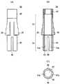
まず、本発明の第1の実施形態について説明する。図1(A)は、本発明の連発式クリップ処置具の一実施例の要部を示す模式的部分断面図であり、図1(B)は、図1(A)と90度異なる角度から見た断面図である。図1(A)および(B)のクリップ処置具10は図中下方へ長く延び、その端部には図7に示す操作部を有している。図7は、図1(A)に示す連発式クリップ処置具の基端側の操作部の一実施例の概略構成を示す部分断面平面図である。図2(A)は、図1(A)に示す連発式クリップ処置具の先端部のクリップ装填部分をより詳細に示す模式的断面図であり、図2(B)は、図2(A)と90度異なる角度から見た断面図である。  First, a first embodiment of the present invention will be described. FIG. 1A is a schematic partial cross-sectional view showing the main part of one embodiment of a repetitive clip treatment device of the present invention, and FIG. 1B is an angle different from that of FIG. 1A by 90 degrees. FIG. 1A and 1B extends long downward in the drawing, and has an operation portion shown in FIG. 7 at an end thereof. FIG. 7 is a partial cross-sectional plan view showing a schematic configuration of one embodiment of the operation unit on the proximal end side of the repetitive clip treatment device shown in FIG. 2A is a schematic cross-sectional view showing in more detail a clip loading portion at the distal end portion of the repetitive clip treatment device shown in FIG. 1A, and FIG. 2B is a schematic cross-sectional view of FIG. It is sectional drawing seen from theangle 90 degrees different from.

図1(A)および(B)に示す、クリップ処置具10は、複数のクリップを連続して使用できる連発式のクリップ処置具であり、図2(A)および(B)に示すように、複数(図2(A)に示す例では3個)のクリップ12(12A、12B、12C)と、隣り合うクリップ12の係合部を覆ってクリップ12の連結状態を維持する連結リング14(14A、14B、14C)と、連結リング14によって連結されたクリップ12を内部に移動可能に収容するシース16と、最後尾のクリップ12Cに接続されたダミークリップ18と、シース16内に移動可能に収納され、接続部材19を介してダミークリップ18に接続された操作ワイヤ20と、操作ワイヤ20がその基端において押引き可能に取り付けられた操作部120(図7参照)とを有する。クリップ12、連結リング14、ダミークリップ18、接続部材19、操作ワイヤ20は、シース16の内部に移動可能に収容されている。シース16は、操作部120に接続される縮径部48(第2の部分)、連結リング14によって連結されたクリップ12を内部に移動可能に収容する拡径部36(第1の部分)、および縮径部48と拡径部36とを接続する継ぎ手82を有する。
図1(A)および(B)、ならびに、図2(A)および(B)は、先頭のクリップ12によるクリップ処置動作開始直前の初期状態を示している。
Theclip treatment tool 10 shown in FIGS. 1 (A) and (B) is a repetitive clip treatment tool that can continuously use a plurality of clips. As shown in FIGS. 2 (A) and (B), A plurality (three in the example shown in FIG. 2A) of clips 12 (12A, 12B, 12C) and a connecting ring 14 (14A) that covers the engaging portions ofadjacent clips 12 and maintains the connection state of theclips 12. , 14B, 14C), asheath 16 that movably accommodates theclip 12 coupled by thecoupling ring 14, adummy clip 18 that is connected to therearmost clip 12C, and movably accommodated in thesheath 16 Theoperation wire 20 connected to thedummy clip 18 via theconnection member 19 and theoperation unit 120 to which theoperation wire 20 is attached so as to be able to be pushed and pulled at the base end thereof (see FIG. 7) Having. Theclip 12, thecoupling ring 14, thedummy clip 18, theconnection member 19, and theoperation wire 20 are accommodated in thesheath 16 so as to be movable. Thesheath 16 includes a diameter-reduced portion 48 (second portion) connected to theoperation portion 120, a diameter-expanded portion 36 (first portion) that accommodates theclip 12 coupled by thecoupling ring 14 so as to be movable inside, And a joint 82 connecting the reduceddiameter portion 48 and theenlarged diameter portion 36.
FIGS. 1A and 1B and FIGS. 2A and 2B show an initial state immediately before the start of the clip treatment operation by thehead clip 12.

1つのクリップ12と1つの連結リング14は、1つの内視鏡用止血クリップ体を構成し、クリップ処置具10は、この止血クリップ体がシース16の拡径部36の先端内部に複数装填されたものである。連続する止血クリップ体の終端は、ダミークリップ18に噛み合い結合し、ダミークリップ18は、接続部材19を介して操作ワイヤ20に接続され、操作ワイヤ20は、シース16の基端部まで延びて、後述する操作部120につながっている。操作部120から操作ワイヤ20を所定の長さだけ牽引し、ダミークリップ18を一方向に所定長さ移動させることで、一連のクリップ12が同量だけ移動し、先頭のクリップ12がそれを保持する連結リング14によって締め付けられて、先頭のクリップ12による止血やマーキング等のためのクリップ処置(クリッピング)が行われる。先頭のクリップ12によるクリップ処置が完了した後、操作ワイヤ20をシース16に対して所定の長さだけ押し出すことで、次のクリップ12が使用可能な状態(スタンバイ状態)となり、続けてクリップ処置を行うことができる。  Oneclip 12 and one connectingring 14 constitute one hemostatic clip body for an endoscope, and theclip treatment tool 10 is loaded with a plurality of the hemostatic clip bodies inside the distal end of theenlarged diameter portion 36 of thesheath 16. It is a thing. The end of the continuous hemostatic clip body is meshed with thedummy clip 18, and thedummy clip 18 is connected to theoperation wire 20 via the connectingmember 19, and theoperation wire 20 extends to the proximal end portion of thesheath 16, It is connected to anoperation unit 120 described later. By pulling theoperation wire 20 from theoperation unit 120 by a predetermined length and moving thedummy clip 18 by a predetermined length in one direction, the series ofclips 12 are moved by the same amount, and the leadingclip 12 holds it. The clip is clamped by the connectingring 14 to perform clip treatment (clipping) for hemostasis or marking by the leadingclip 12. After the clip treatment by thefirst clip 12 is completed, theoperation wire 20 is pushed out by a predetermined length with respect to thesheath 16, so that thenext clip 12 can be used (standby state), and then the clip treatment is performed. It can be carried out.

図2(A)および(B)は、先頭のクリップ12Aがシース16の先端から突出した状態の図としてあるが、クリップ12等をシース16へ装填するときは、後述する図12(C)に示すように、先頭のクリップ12Aがシース16の拡径部36の内部に完全に納まった状態でセットされる。また、図2(A)および(B)ではクリップ12を3つとし、3連発式のクリップ処置具10としてあるが、クリップ12の数は、2つ以上いくつであってもよい。  FIGS. 2A and 2B show the state in which the leadingclip 12A protrudes from the distal end of thesheath 16, but when theclip 12 or the like is loaded into thesheath 16, FIG. 12C will be described later. As shown, the leadingclip 12A is set in a state of being completely accommodated in theenlarged diameter portion 36 of thesheath 16. 2A and 2B, the number of theclips 12 may be two or more. However, the number of theclips 12 may be two or more.

図3は、図1(A)に示す連発式クリップ処置具のクリップの斜視図である。同図に示すように、クリップ12は、爪部22に対して180度ターンしたターン部24を有するクローズクリップである。すなわち、クリップ12は、一枚の細長い板を180度湾曲させて閉塞端を作った後、その両片を交差させ、かつ2つの開放端に、端部が対向するように屈曲させて爪部22,22を形成した形状をしている。この交差部26を境にして、開放端側が腕部28,28であり、閉塞端側がターン部24である。腕部28,28の中央部分には、部分的に広幅とされた凸部30,30が形成されている。クリップ12には、生体適合性のある金属を用いることができ、例えば、ばね用ステンレス鋼であるSUS631などを用いることができる。  FIG. 3 is a perspective view of a clip of the repetitive clip treatment tool shown in FIG. As shown in the figure, theclip 12 is a closed clip having aturn part 24 turned 180 degrees with respect to theclaw part 22. That is, theclip 12 is made by bending a single elongated plate 180 degrees to form a closed end, and then intersecting the two pieces and bending the two open ends so that the ends are opposed to each other. 22 and 22 are formed. With thisintersection 26 as a boundary, the open end side is thearm portions 28 and 28, and the closed end side is theturn portion 24.Convex portions 30, 30 that are partially wide are formed at the central portions of thearm portions 28, 28. Theclip 12 can be made of a biocompatible metal, such as SUS631 that is stainless steel for springs.

クリップ12は、その交差部26に嵌められた連結リング14の先端部分(後述する締付部40)が、腕部28,28を押圧しながら爪部22,22の方へ向かって所定量移動することにより、その腕部28,28および爪部22,22が閉じ、爪部22,22において所定の嵌合力を発揮する。  Theclip 12 is moved by a predetermined amount toward theclaw portions 22 and 22 while the front end portion (clampingportion 40 described later) of the connectingring 14 fitted to the intersectingportion 26 presses thearm portions 28 and 28. By doing so, thearm portions 28 and 28 and theclaw portions 22 and 22 are closed, and a predetermined fitting force is exhibited in theclaw portions 22 and 22.

爪部22,22は、出血部や病変組織除去後の処置部等の対象部を確実に摘むために、V字のオス型とメス型に形成されている。また、図3に示すように、クリップ12の腕部28は、交差部26から凸部30に掛けて徐々に幅が広くなっている。
凸部30は、連結リング14の先端側の開口および基端側の開口の、凸部30が当接する部分よりも広い幅とされている。したがって、クリップ12の凸部30以外の部分は、連結リング14の内部に侵入できるが、凸部30は、連結リング14の先端側からも基端側からも、その内部に侵入できない。
The nail | clawparts 22 and 22 are formed in the V-shaped male type | mold and female type | mold in order to pick up target parts, such as a treatment part after a bleeding part and a lesioned tissue removal, reliably. Further, as shown in FIG. 3, thearm portion 28 of theclip 12 is gradually widened from the intersectingportion 26 to theconvex portion 30.
Theconvex portion 30 has a width wider than the portion of the opening on the distal end side and the opening on the proximal end side of theconnection ring 14 with which theconvex portion 30 abuts. Therefore, portions other than theconvex portion 30 of theclip 12 can enter the inside of the connectingring 14, but theconvex portion 30 cannot enter the inside from the front end side or the base end side of the connectingring 14.

図2(A)および(B)に示すように、第1クリップ12Aと第2クリップ12Bは、第2クリップ12Bの爪部22が第1クリップ12Aのターン部24に係合して閉じた状態で連結リング14Aに保持されることで連結状態とされる。図2(A)に示すように、第2クリップ12Bの爪部22,22は、第1クリップ12Aのターン部24に直交方向に噛みあって結合し、第1クリップ12Aと第2クリップ12Bは、90度異なる向きで連結される。同様に、第2クリップ12Bと第3クリップ12Cも、90度異なる向きで連結される。  As shown in FIGS. 2A and 2B, thefirst clip 12A and thesecond clip 12B are closed with theclaw portion 22 of thesecond clip 12B engaged with theturn portion 24 of thefirst clip 12A. The connection state is established by being held by theconnection ring 14A. As shown in FIG. 2 (A), theclaw portions 22 and 22 of thesecond clip 12B are engaged with theturn portion 24 of thefirst clip 12A in the orthogonal direction, and thefirst clip 12A and thesecond clip 12B are connected to each other. , They are connected in different directions by 90 degrees. Similarly, thesecond clip 12B and thethird clip 12C are also connected in directions different by 90 degrees.

連結リング14は、2つのクリップ12,12との係合部を覆って連結状態を維持しつつ、シース16の拡径部36に進退可能に嵌入されている。すなわち、連結リング14は、その外径がシース16の拡径部36の内径とほぼ等しく、クリップ12の移動に伴ってシース16の拡径部36内をスムーズに進退移動することができる。
図4(A)〜(C)に、このような連結リングの一実施例の概略構成を示す。図4(A)は、連結リング14の正面図、図4(B)は断面図、図4(C)は、底面図である。
Theconnection ring 14 is fitted into the diameter-expandedportion 36 of thesheath 16 so as to be able to advance and retract while covering the engagement portion with the twoclips 12 and 12 and maintaining the connection state. That is, the outer diameter of theconnection ring 14 is substantially equal to the inner diameter of theenlarged diameter portion 36 of thesheath 16, and can smoothly move forward and backward within theenlarged diameter portion 36 of thesheath 16 as theclip 12 moves.
4A to 4C show a schematic configuration of an embodiment of such a connection ring. 4A is a front view of the connectingring 14, FIG. 4B is a cross-sectional view, and FIG. 4C is a bottom view.

図4(A)〜(C)に示す連結リング14は、締付部40と保持部42とから成る。連結リング14は、樹脂製の保持部42の先端に、金属製の締付部40を固定し、2部材で一体構造とされている。樹脂製の保持部42が連結状態の維持およびクリップの連結リング内での保持を担当し、金属製の締付部40がクリップの締め付けを担当する。なお、連結リング14は、締付部40および保持部42の両機能を発揮できれば、1部材で形成してもよい。  Theconnection ring 14 shown in FIGS. 4A to 4C includes a tighteningportion 40 and a holdingportion 42. Theconnection ring 14 has ametal fastening part 40 fixed to the tip of aresin holding part 42 and has an integral structure with two members. Theresin holding part 42 is in charge of maintaining the connected state and holding the clip in the connecting ring, and themetal fastening part 40 is in charge of fastening the clip. Theconnection ring 14 may be formed of one member as long as both functions of the tighteningportion 40 and the holdingportion 42 can be exhibited.

締付部40は、連結リング14の先端側に取り付けられた金属製の円筒状(リング状)の部品であり、クリップ12の交差部26近傍の幅よりも大きく、凸部30の幅よりも小さい内径の穴が形成されている。したがって、締付部40は、保持するクリップ12の交差部26の近傍を移動することができるが、凸部30を超えて先端側へは抜けられない。すなわち凸部30が、クリップ12に対して前進する連結リング14の移動限界を決めるストッパとして機能する。  The tighteningportion 40 is a metal cylindrical (ring-shaped) part attached to the distal end side of theconnection ring 14, and is larger than the width of theclip 12 near theintersection 26 and larger than the width of theconvex portion 30. A small inner diameter hole is formed. Therefore, the tighteningportion 40 can move in the vicinity of the intersectingportion 26 of theclip 12 to be held, but cannot be pulled out beyond theconvex portion 30. That is, theconvex portion 30 functions as a stopper that determines the movement limit of the connectingring 14 that moves forward with respect to theclip 12.

締付部40は、クリップ12の交差部26の近傍の所定位置にセットされる。締付部40は、その初期位置から、クリップ12の腕部28が幅広になる、交差部26から凸部30の側へ移動することで、拡開しているクリップ12の両方の腕部28,28を閉じさせて固定する締め付け機能を有している。締付部40には、生体適合性のある金属が用いられ、例えばステンレス鋼SUS304を用いることができる。締付部40を金属製としたことで、金属製のクリップ12に対して締付力となる摩擦力を発揮させることができる。
保持部42は、樹脂成形された概略円筒状(リング状)の部品である。保持部42は、先のクリップ12を保持する第1領域32と、先のクリップに連結した状態で次のクリップ12を保持する連結保持領域である第2領域34とを有している。
The tighteningportion 40 is set at a predetermined position in the vicinity of the intersectingportion 26 of theclip 12. The tighteningportion 40 moves from the initial position to theconvex portion 30 side from the intersectingportion 26 where thearm portion 28 of theclip 12 becomes wide, so that both thearm portions 28 of theclip 12 that has spread. , 28 is closed and fixed. For the tighteningportion 40, a biocompatible metal is used. For example, stainless steel SUS304 can be used. Since the tighteningportion 40 is made of metal, it is possible to exert a frictional force as a tightening force on themetal clip 12.
The holdingportion 42 is a resin-molded, generally cylindrical (ring-shaped) part. The holdingunit 42 includes afirst area 32 that holds theprevious clip 12 and asecond area 34 that is a connected holding area that holds thenext clip 12 in a state of being connected to the previous clip.

第1領域32には、クリップ12のターン部24を収容可能な、締付部40の穴よりも大きな円形の穴が形成されている。第1領域32の先端部の外面には、締付部40を嵌めるための段付き部が形成されており、締付部40と保持部42とは、シース16の拡径部36に装填された状態およびクリッピング操作時において外れない程度の締まり嵌めで嵌め合わされている。また、第1領域32は、連結リング14本体の軸に対してスカート状に傾斜して広がるスカート部38を有している。  In thefirst region 32, a circular hole larger than the hole of the tighteningportion 40 that can accommodate theturn portion 24 of theclip 12 is formed. A stepped portion for fitting the tighteningportion 40 is formed on the outer surface of the distal end portion of thefirst region 32, and the tighteningportion 40 and the holdingportion 42 are loaded into the diameter-expandedportion 36 of thesheath 16. And are fitted with an interference fit that does not come off during clipping operation. Further, thefirst region 32 has askirt portion 38 that is inclined and spreads in a skirt shape with respect to the axis of the connectingring 14 main body.

スカート部38は、先端側、すなわち図4(A)および(B)における上方の付け根が保持部42の本体につながっており、下方の広がり部分が、本体から一部切り離されて、半径方向に広がったり閉じたりするようになっている。スカート部38は、クリップ12の牽引方向、すなわち図4の上下方向において同じ位置に、180度離れた両側の2箇所に形成されている。  Theskirt portion 38 has a distal end side, that is, an upper root in FIGS. 4A and 4B connected to the main body of the holdingportion 42, and a lower spread portion is partly cut off from the main body so as to extend in the radial direction. It spreads and closes. Theskirt portions 38 are formed at two positions on both sides separated by 180 degrees at the same position in the pulling direction of theclip 12, that is, the vertical direction in FIG.

両側のスカート部38、38は、外力が付与されない自然状態では、図4(A)に示すように、スカート状に広がる。このとき、保持部42の第1領域32の内部は、図4(B)に示すように、円柱状の空間となっている。一方、連結リング14がシース16の拡径部36内へ装填されるときは、例えば図2(B)の2つめの連結リング14Bに示すように、スカート部38が内側に押し込まれて内部空間へ入り込み、スカート部38の内周側の部分が、第1領域32に保持されるクリップ12Bのターン部24の側面(エッジ部)を押圧して、クリップ12Bが連結リング14B内で回転方向および進退方向に移動しないように保持する。  Theskirt portions 38 on both sides expand in a skirt shape as shown in FIG. 4A in a natural state where no external force is applied. At this time, the inside of thefirst region 32 of the holdingportion 42 is a columnar space as shown in FIG. On the other hand, when the connectingring 14 is loaded into theenlarged diameter portion 36 of thesheath 16, for example, as shown in a second connectingring 14B in FIG. The inner peripheral side portion of theskirt portion 38 presses the side surface (edge portion) of theturn portion 24 of theclip 12B held in thefirst region 32, so that theclip 12B rotates in the connectingring 14B and Hold it so that it does not move forward and backward.

スカート部38,38は、図2(A)の1つめの連結リング14Aに示すように、シース16(拡径部36)の先端から抜け出ると同時に、それ自体の弾性によって開き、クリップ12Aの保持を解除するとともに、シース16(拡径部36)の内径よりも広幅となって、連結リング14Aのシース16(拡径部36)内への後退を阻止する。この状態で操作ワイヤ20が引かれ、クリップ12Aが後退することで、連結リング14Aがクリップ12Aに対して相対的に前進し、クリップ12Aを締め付ける。  As shown in the first connectingring 14A in FIG. 2A, theskirt portions 38, 38 are pulled out from the distal end of the sheath 16 (the expanded diameter portion 36), and at the same time, are opened by their own elasticity to hold theclip 12A. Is released, and the width of the connectingring 14A becomes wider than the inner diameter of the sheath 16 (expanded diameter portion 36) to prevent the connectingring 14A from being retracted into the sheath 16 (expanded diameter section 36). In this state, theoperation wire 20 is pulled and theclip 12A moves backward, whereby the connectingring 14A moves forward relative to theclip 12A and tightens theclip 12A.

したがって、スカート部38は、シース16(拡径部36)の内部では内側へ閉じることができ、シース16(拡径部36)の先端から出て外力から解放されるとスカート状に広がるように、弾性を有していることが必要である。それとともに、スカート部38は、シース16(拡径部36)の内部でクリップ12を保持できる剛性と、シース16(拡径部36)の先端でクリップ12の締付力の反力に耐える剛性とを有していることも必要である。  Therefore, theskirt portion 38 can be closed inward within the sheath 16 (the enlarged diameter portion 36), and spreads in a skirt shape when it is released from the distal end of the sheath 16 (the enlarged diameter portion 36) and released from the external force. It is necessary to have elasticity. At the same time, theskirt portion 38 is rigid enough to hold theclip 12 inside the sheath 16 (diameter enlarged portion 36) and rigid enough to withstand the reaction force of the clamping force of theclip 12 at the distal end of the sheath 16 (diameter enlarged portion 36). It is also necessary to have

これらの観点から、保持部42には、生体適合性があり、かつ、スカート部38に要求される弾性および剛性を満たす材料が用いられる。また、その形状は、スカート部38に要求される弾性および剛性を満たすように定められる。このような保持部42の材料としては、例えば、PPSU(ポリフェニルサルホン、polyphenylsulfone)などを用いることができる。製造の容易さから、保持部42は、一体成形されるのが好ましい。  From these viewpoints, the holdingportion 42 is made of a material that is biocompatible and satisfies the elasticity and rigidity required for theskirt portion 38. The shape is determined so as to satisfy the elasticity and rigidity required for theskirt portion 38. For example, PPSU (polyphenylsulfone) can be used as the material of the holdingunit 42. From the standpoint of ease of manufacture, the holdingportion 42 is preferably integrally formed.

第2領域34は、第1領域32の基端側に設けられており、第1領域32に保持されるクリップ12に係合する次のクリップ12を、その爪部22,22が先のクリップ12のターン部24の閉塞端(尾部)を挟んで閉じた状態で保持する。  Thesecond region 34 is provided on the proximal end side of thefirst region 32, and theclaw portions 22, 22 of thenext clip 12 that engages with theclip 12 held in thefirst region 32 are the previous clips. The closed end (tail) of the 12turn parts 24 is held in a closed state.

第2領域34は、領域長さとして、クリップ12に対して初期位置にセットされた締付部40が、クリップ12の締め付けを完了するまでに要する移動長さとほぼ等しい長さを持つ。すなわち、連結リング14の第2領域34は、クリップ12が連結リング14に対して相対的に後退して締め付けられていく間、その内部に保持する2つのクリップ12,12の連結を保持して、後ろのクリップ12の牽引力が先端のクリップ12へ伝達されるようにするとともに、締め付けが完了したときには、2つのクリップ12,12の係合部が第2領域34から外れることにより、そのクリップ12,12の連結を解除する。  Thesecond region 34 has a length substantially equal to the moving length required for the tighteningportion 40 set at the initial position with respect to theclip 12 to complete the tightening of theclip 12 as the region length. That is, thesecond region 34 of theconnection ring 14 holds the connection between the twoclips 12 and 12 held therein while theclip 12 is retracted and tightened relative to theconnection ring 14. In addition, the traction force of therear clip 12 is transmitted to thefront clip 12, and when the tightening is completed, the engaging portions of the twoclips 12, 12 are disengaged from thesecond region 34, whereby theclip 12 , 12 are released.

第2領域34には、図4(C)に示すように、第1領域32の基端側部分と同じ内径の穴43が形成され、さらに、その対向する2箇所に溝(凹部)43aが形成されている。溝43a,43aは、第2領域34に保持されるクリップ12の腕部28,28を、爪部22,22が閉じた状態で収容可能である。また、第2領域34には、図4(A)〜(C)に示すように、その基端から切り込むスリット46が2箇所に形成されている。  In thesecond region 34, as shown in FIG. 4C, ahole 43 having the same inner diameter as that of the proximal end portion of thefirst region 32 is formed, and a groove (concave portion) 43a is formed at two opposing positions. Is formed. Thegrooves 43a and 43a can accommodate thearm portions 28 and 28 of theclip 12 held in thesecond region 34 with theclaw portions 22 and 22 closed. Moreover, as shown to FIG. 4 (A)-(C), theslit 46 cut | disconnected from the base end is formed in the 2nd area |region 34 at two places.

溝43a,43aは、第2領域34に保持されるクリップ12の爪部22の開閉方向(図4(B)中、左右方向)の2箇所に設けられている。第2領域34に保持されるクリップ12の腕部28,28の板面は、溝43a,43aの内壁に当接する。溝43aの幅(開口幅)は、クリップ12の腕部28の最大幅よりわずかに大きく、一方の溝43aの壁面から他方の溝43aの壁面までの距離は、クリップ12の2つの爪部22,22の長さ(拡開方向の長さ)を足し合わせた長さにほぼ等しい。また、溝43aの幅は、腕部28に形成された凸部30の幅よりは小さい。したがって、第2領域34に保持されるクリップ12の凸部30は、溝43aに進入できない。  Thegrooves 43a and 43a are provided at two locations in the opening / closing direction (left and right direction in FIG. 4B) of theclaw portion 22 of theclip 12 held in thesecond region 34. The plate surfaces of thearm portions 28 and 28 of theclip 12 held in thesecond region 34 abut against the inner walls of thegrooves 43a and 43a. The width (opening width) of thegroove 43a is slightly larger than the maximum width of thearm portion 28 of theclip 12, and the distance from the wall surface of onegroove 43a to the wall surface of theother groove 43a is the twoclaw portions 22 of theclip 12. , 22 (length in the expanding direction) is approximately equal to the total length. Further, the width of thegroove 43 a is smaller than the width of theconvex portion 30 formed in thearm portion 28. Therefore, theconvex portion 30 of theclip 12 held in thesecond region 34 cannot enter thegroove 43a.

なお、両溝43a,43aの壁面から壁面までの距離は、先のクリップ12のターン部24と、次のクリップ12の爪部22,22との係合が外れない寸法にすればよく、2つの爪部22,22の長さと、ターン部24の爪部22,22が係合する部分の幅とを足し合わせた長さよりも短くすればよい。例えば、第2領域34に保持されるクリップ12の爪部22,22は、少し重なった状態となっていてもよいし、爪部22,22の間にわずかな隙間がある状態で、先のクリップ12との連結が維持されるようにしてもよい。  In addition, the distance from the wall surface to the wall surface of bothgrooves 43a and 43a should just be a dimension in which the engagement between theturn part 24 of theprevious clip 12 and theclaw parts 22 and 22 of thenext clip 12 is not released. What is necessary is just to make shorter than the length which added the length of the two nail | clawparts 22 and 22 and the width | variety of the part which the nail | clawparts 22 and 22 of theturn part 24 engage. For example, theclaw portions 22 and 22 of theclip 12 held in thesecond region 34 may be in a slightly overlapped state, or with a slight gap between theclaw portions 22 and 22, The connection with theclip 12 may be maintained.

2つのクリップ12,12の係合部は、第2領域34の、第1領域32との境目に近接する部分に保持される。先のクリップ12(例えば、図2(B)の連結リング14Bにおけるクリップ12B)は、シース16(拡径部36)の内部においては、ターン部24が第1領域32の閉じたスカート部38によって保持されているので、進退移動および回転移動が抑えられている。また、先のクリップ12に係合する次のクリップ12(例えば、図2(B)の連結リング14Bにおけるクリップ12C)は、第2領域34の溝43aによって先のクリップと90度異なる方向に保持されることにより回転移動が抑えられ、進退移動が抑えられた先のクリップに係合することにより、進退移動が抑えられている。すなわち、前後のクリップの係合部は、遊びが非常に小さい状態で、連結リング14によって保持される。  The engaging portions of the twoclips 12 and 12 are held in a portion of thesecond region 34 that is close to the boundary with thefirst region 32. The previous clip 12 (for example, theclip 12B in the connectingring 14B in FIG. 2B) is configured such that theturn portion 24 is formed by theclosed skirt portion 38 in thefirst region 32 inside the sheath 16 (expanded diameter portion 36). Since it is held, forward / backward movement and rotational movement are suppressed. Further, thenext clip 12 that engages with the previous clip 12 (for example, theclip 12C in theconnection ring 14B in FIG. 2B) is held in a direction different from the previous clip by 90 degrees by thegroove 43a of thesecond region 34. Thus, the rotational movement is suppressed, and the forward / backward movement is suppressed by engaging the previous clip in which the forward / backward movement is suppressed. That is, the engaging portions of the front and rear clips are held by theconnection ring 14 with a very small play.

スリット46は、スカート部38,38から90度ずれた2箇所に、第2領域34の上端よりも浅い位置まで形成されている。言い換えれば、スリット46は、第2領域34に保持されるクリップ12の拡開方向から90度ずれた位置に設けられている。  Theslits 46 are formed at two positions shifted by 90 degrees from theskirt portions 38 and 38 to a position shallower than the upper end of thesecond region 34. In other words, theslit 46 is provided at a position shifted by 90 degrees from the spreading direction of theclip 12 held in thesecond region 34.

スリット46を設けることにより、連結リング14のフレキシブル性を向上させることができ、クリップ処置具10は、曲率の小さい湾曲部を通過することができる。また、スリット46を設けることにより、連結リング14の裾(基端部)が一部めくれるようになるため、シース16(拡径部36)へのクリップ12の装填前に前後のクリップ12,12を連結させる際に、連結リング14の裾をめくることで容易に連結させることができるという利点もある。  By providing theslit 46, the flexibility of the connectingring 14 can be improved, and theclip treatment tool 10 can pass through a curved portion having a small curvature. Further, since theslit 46 is provided, the skirt (base end portion) of the connectingring 14 is partially turned up, so that the front andrear clips 12, 12 are loaded before theclip 12 is loaded into the sheath 16 (the enlarged diameter portion 36). When connecting the two, there is an advantage that theconnection ring 14 can be easily connected by turning the skirt.

スリット46の深さは、スカート部38よりも浅い位置までとされており、連結リング14の強度が大幅に低下するのが防止されている。また、スリット46の深さは、第1領域32に保持されるクリップ12の後端の位置、すなわちクリップ12,12の係合位置よりも浅い位置までとされており、シース16(拡径部36)に装填される前の連結クリップユニットにおいても、連結リング14の第2領域34におけるクリップ12の保持を保つことができる。  The depth of theslit 46 is set to a position shallower than theskirt portion 38, and the strength of the connectingring 14 is prevented from greatly decreasing. Further, the depth of theslit 46 is set to the position of the rear end of theclip 12 held in thefirst region 32, that is, a position shallower than the engaging position of theclips 12 and 12, and the sheath 16 (the enlarged diameter portion). Theclip 12 in thesecond region 34 of theconnection ring 14 can be maintained even in the connection clip unit before being loaded in 36).

図2(A)および(B)に示すように、第1クリップ12Aのターン部24に第2クリップ12Bの爪部22,22が係合し、その係合部を連結リング14Aが保持する。連結リング14A(その第2領域34)の内壁によって、第2クリップ12Bの爪部22,22は閉じた状態に保持されている。それにより、第1クリップ12Aと第2クリップ12Bの連結状態が維持される。同様に、第2クリップ12Bと第3クリップ12Cとの連結状態は、連結リング14Bによって、第3クリップ12Cとダミークリップ18との連結状態は、連結リング14Cによって維持される。  As shown in FIGS. 2A and 2B, theclaw portions 22 of thesecond clip 12B engage with theturn portion 24 of thefirst clip 12A, and thecoupling ring 14A holds the engaging portion. Theclaw portions 22 of thesecond clip 12B are held in a closed state by the inner wall of theconnection ring 14A (the second region 34). Thereby, the connection state of thefirst clip 12A and thesecond clip 12B is maintained. Similarly, the connection state between thesecond clip 12B and thethird clip 12C is maintained by theconnection ring 14B, and the connection state between thethird clip 12C and thedummy clip 18 is maintained by theconnection ring 14C.

最後尾のクリップ12Cには、クリップ処置には用いられないダミークリップ18が係合している。ダミークリップ18は、先端部に、クリップ12の交差部26から開放端側半分の部分と類似の形状をしたバネ性を持つ部分を有しており、爪部を閉じた状態でクリップ12Cのターン部に係合し、爪部を開くとクリップ12Cを開放する。ダミークリップ18の基端部には接続部材19があり、この接続部材19に操作ワイヤ20が接続されている。  Adummy clip 18 that is not used for clip treatment is engaged with thelast clip 12C. Thedummy clip 18 has a spring-like portion having a shape similar to that of the half on the open end side from theintersection 26 of theclip 12 at the tip, and theclip 12C is turned with the claw closed. Theclip 12C is released when the claw portion is opened. Aconnection member 19 is provided at the proximal end portion of thedummy clip 18, and anoperation wire 20 is connected to theconnection member 19.

シース16は、例えば、金属ワイヤを密着巻きした可撓性のコイルシースである。シース16は、拡径部36(第1の部分)と、縮径部48(第2の部分)と、継ぎ手82とを有する。拡径部36はシース16の先端側に位置し、先端側から連結リング14によって連結された複数のクリップ12を内部に移動可能に収容することができる。縮径部48は拡径部36よりも細く、シース16の基端側に位置し、その基端が操作部120に接続される。継ぎ手82は、径の異なる拡径部36の基端と縮径部48の先端とを溶接または接着等により接続し、拡径部36、縮径部48および継ぎ手82は、シース16として一体となっている。  Thesheath 16 is, for example, a flexible coil sheath in which a metal wire is tightly wound. Thesheath 16 has an enlarged diameter portion 36 (first portion), a reduced diameter portion 48 (second portion), and a joint 82. Theenlarged diameter portion 36 is located on the distal end side of thesheath 16 and can accommodate therein the plurality ofclips 12 connected by theconnection ring 14 from the distal end side. The reduceddiameter portion 48 is thinner than theenlarged diameter portion 36 and is located on the proximal end side of thesheath 16, and the proximal end thereof is connected to theoperation portion 120. The joint 82 connects the base end of theenlarged diameter portion 36 having a different diameter and the distal end of the reduceddiameter portion 48 by welding or bonding, and theenlarged diameter portion 36, the reduceddiameter portion 48, and the joint 82 are integrally formed as asheath 16. It has become.

シース16の拡径部36、縮径部48および継ぎ手82の関係を図5に示す。
シース16は、その拡径部36の内部に、クリップ12とダミークリップ18および接続部材19が移動可能に嵌入され、縮径部48および継ぎ手82の内部に、クリップ12にダミークリップ18および接続部材19を介して接続されている操作ワイヤ20を収納するものである。
FIG. 5 shows the relationship between theenlarged diameter portion 36, the reduceddiameter portion 48, and the joint 82 of thesheath 16.
In thesheath 16, theclip 12, thedummy clip 18, and theconnection member 19 are movably fitted inside theenlarged diameter portion 36, and thedummy clip 18 and the connection member are attached to theclip 12 inside the reduceddiameter portion 48 and the joint 82. Theoperation wire 20 connected via 19 is accommodated.

シース16の拡径部36の内径は、連結リング14の外径とほぼ等しく、かつ、先のクリップ12のターン部24と、次のクリップ12の爪部22,22との係合が解除される寸法とされている。すなわち、シース16の拡径部36の内径は、2つの爪部22,22の長さと、ターン部24の爪部22,22が係合する部分の幅とを足し合わせた長さよりも大きい。
シース16の拡径部36の長さは、クリップ12の数、ダミークリップ18、接続部材19および、クリッピング処置時の動作代を合わせたものであり、例えば、クリップ12の全長が20mm、ダミークリップ18の全長が18mm、接続部材19の全長が6mmのときに、3連発の連発式クリップ処置具であれば62mmとするのが好ましい。
シース16の縮径部48の内径d2は、操作ワイヤ20の外径Dwよりもわずかに大きくなっている。すなわち、シース16の縮径部48内を挿通する操作ワイヤ20は、進退自由に動ける状態となっている。
The inner diameter of theenlarged diameter portion 36 of thesheath 16 is substantially equal to the outer diameter of theconnection ring 14, and the engagement between theturn portion 24 of theprevious clip 12 and theclaws 22, 22 of thenext clip 12 is released. Dimensions. That is, the inner diameter of theenlarged diameter portion 36 of thesheath 16 is larger than the total length of the lengths of the twoclaw portions 22 and 22 and the width of the portion where theclaw portions 22 and 22 of theturn portion 24 are engaged.
The length of the diameter-expandedportion 36 of thesheath 16 is a combination of the number ofclips 12, the dummy clips 18, theconnection member 19, and the operation allowance during clipping treatment. For example, the total length of theclip 12 is 20 mm. When the total length of 18 is 18 mm and the total length of the connectingmember 19 is 6 mm, it is preferable that the length is 62 mm for a three-shot continuous clip treatment instrument.
The inner diameter d2 of the reduceddiameter portion 48 of thesheath 16 is slightly larger than the outer diameter Dw of theoperation wire 20. That is, theoperation wire 20 inserted through the reduceddiameter portion 48 of thesheath 16 is in a state where it can freely move forward and backward.

シース16の先端部分を除く大部分を占める縮径部48の範囲では、操作ワイヤ20とシース16との間隔が小さくなり、操作ワイヤ20の中心をシース16の中心100(以下、シース中心100という。)にほぼ一致させることができ、シース16が湾曲している部分でも、操作ワイヤ20の経路長をシース中心100の経路長とほぼ等しくすることができる。さらに、シース16を細くすることでクリップ処置具10の質量を軽くすることができる。  In the range of the reduceddiameter portion 48 that occupies most of thesheath 16 excluding the distal end portion, the distance between theoperation wire 20 and thesheath 16 is small, and the center of theoperation wire 20 is referred to as thecenter 100 of the sheath 16 (hereinafter referred to as the sheath center 100). .), And the path length of theoperation wire 20 can be made substantially equal to the path length of thesheath center 100 even in a portion where thesheath 16 is curved. Furthermore, the mass of theclip treatment device 10 can be reduced by making thesheath 16 thinner.

しかし、シース16の先端部分を除く大部分を細くすると、シース16の縮径部48と操作ワイヤ20との隙間が少なくなり、操作ワイヤ20とシース16との接触により摩擦が発生する場合がある。このため、操作ワイヤ20とシース16との接触による摩擦の発生を抑えるために、シース16の縮径部48の内側または、操作ワイヤ20に潤滑剤を塗布することが好ましい。  However, if most of thesheath 16 except for the distal end portion is thinned, the gap between the reduceddiameter portion 48 of thesheath 16 and theoperation wire 20 is reduced, and friction may occur due to contact between theoperation wire 20 and thesheath 16. . Therefore, in order to suppress the generation of friction due to the contact between theoperation wire 20 and thesheath 16, it is preferable to apply a lubricant to the inside of the reduceddiameter portion 48 of thesheath 16 or to theoperation wire 20.

シース16の先端部分の拡径部36の範囲では、クリップ12、連結リング14、ダミークリップ18および接続部材19を収納することができ、それらの各部材がクリップ処置のために移動することができる。しかし、シース16と操作ワイヤ20との隙間が大きいため、操作ワイヤ20が座屈しやすくなり、操作部120での操作ワイヤ20の移動量が正確にシース16の先端部に伝わらない可能性が出てくる。  In the range of theenlarged diameter portion 36 at the distal end portion of thesheath 16, theclip 12, thecoupling ring 14, thedummy clip 18, and theconnection member 19 can be accommodated, and each of these members can be moved for the clip treatment. . However, since the gap between thesheath 16 and theoperation wire 20 is large, theoperation wire 20 is likely to buckle, and the movement amount of theoperation wire 20 in theoperation unit 120 may not be accurately transmitted to the distal end portion of thesheath 16. Come.

そこで、シース16の拡径部36の長さは、クリップ12の連発数により求められる必要最小限の長さとし、クリップ12の連発数に応じて変更することが好ましい。例えば、5連発用のシースに3発しかクリップ12を実装しない場合、3連発用のシースに比べ、使用しない2発分の長さだけシース16の拡径部36が長い。よって、全長が同じとしたならば、シース16の縮径部48はその分短くなる。そうすると、シース16と操作ワイヤ20との経路長差が、本来の3連発用のシースを用いた場合に比べ、大きくなってしまう。そこで、連発クリップ数に応じてシース16の拡径部36の長さを変更することによって、連発クリップ数に応じた最適なシース16を用いることができることが好ましい。  Therefore, it is preferable that the length of the diameter-expandedportion 36 of thesheath 16 is a minimum necessary length determined by the number of continuous shots of theclip 12 and is changed according to the number of continuous shots of theclip 12. For example, when only threeclips 12 are mounted on a five-shot sheath, the expandeddiameter portion 36 of thesheath 16 is longer than the three-shot sheath by the length of two unused shots. Therefore, if the overall length is the same, the reduceddiameter portion 48 of thesheath 16 is shortened accordingly. As a result, the path length difference between thesheath 16 and theoperation wire 20 becomes larger than when the original triple-running sheath is used. Therefore, it is preferable that theoptimum sheath 16 corresponding to the number of consecutive clips can be used by changing the length of theenlarged diameter portion 36 of thesheath 16 according to the number of consecutive clips.

継ぎ手82は、径の異なるシース16の拡径部36と縮径部48とを接続する。継ぎ手82は、例えば、図6に示すような中央部分の内外に突起をもつ円筒形である。継ぎ手82は、シース16の拡径部36の内径D2(図5参照)よりも小さい外径を持つものとし、接着剤を用いて拡径部36に取り付けてもよいし、シース16の拡径部36に嵌入することができれば、シース16の拡径部36の内径D2よりも大きい外径を持つものでもよい。例えば、シース16の拡径部36がコイルシースである場合には、継ぎ手82の外径がシース16の拡径部36の内径D2よりも大きい外径を持っていたとしても、コイルシースが拡がることで嵌入することができる。また、しまりばめとすることでシース16の拡径部36と継ぎ手82を、強固に接続することができる。  The joint 82 connects theenlarged diameter portion 36 and the reduceddiameter portion 48 of thesheath 16 having different diameters. The joint 82 has, for example, a cylindrical shape having protrusions on the inside and outside of the central portion as shown in FIG. The joint 82 has an outer diameter smaller than the inner diameter D2 (see FIG. 5) of the diameter-expandedportion 36 of thesheath 16, and may be attached to the diameter-expandedportion 36 using an adhesive, or the diameter of thesheath 16 may be increased. As long as it can be fitted into theportion 36, thesheath 16 may have an outer diameter larger than the inner diameter D <b> 2 of theenlarged diameter portion 36. For example, when theenlarged diameter portion 36 of thesheath 16 is a coil sheath, even if the outer diameter of the joint 82 has an outer diameter larger than the inner diameter D2 of theenlarged diameter portion 36 of thesheath 16, the coil sheath is expanded. Can be inserted. Further, the interference fit can firmly connect theenlarged diameter portion 36 of thesheath 16 and the joint 82.

継ぎ手82の長手方向中心部には、シース16の拡径部36に挿入したときに突き当てとなるように、外側の突き当て82a、すなわちリング状の突起が設けられている。この外側の突き当て82aの外径は、シース16の拡径部36の内径D2よりも大きく、シース16の拡径部36の外径D1より小さいか同じとなっている。  Anouter abutment 82a, that is, a ring-shaped projection is provided at the center in the longitudinal direction of the joint 82 so as to be abutted when inserted into theenlarged diameter portion 36 of thesheath 16. The outer diameter of theouter abutment 82a is larger than the inner diameter D2 of theenlarged diameter portion 36 of thesheath 16, and smaller than or equal to the outer diameter D1 of theenlarged diameter portion 36 of thesheath 16.

継ぎ手82の内側は、操作ワイヤ20が挿通可能となっている。継ぎ手82の内径は、シース16の縮径部48の外径d1よりも大きくし、接着剤を用いて拡径部36に取り付けてもよいし、シース16の縮径部48を嵌入することができれば、シース16の縮径部48の外径d1よりも小さくてもよい。例えば、シース16の縮径部48がコイルシースである場合には、シース16の縮径部48の外径d1よりも継ぎ手82の内径が小さくても、コイルシースが縮まることで嵌入することができる。また、しまりばめとすることでシース16の縮径部48と継ぎ手82を、強固に接続することができる。  Theoperation wire 20 can be inserted inside the joint 82. The inner diameter of the joint 82 is larger than the outer diameter d1 of the reduceddiameter portion 48 of thesheath 16, and may be attached to theenlarged diameter portion 36 using an adhesive, or the reduceddiameter portion 48 of thesheath 16 may be fitted. If possible, the outer diameter d1 of the reduceddiameter portion 48 of thesheath 16 may be smaller. For example, when the reduceddiameter portion 48 of thesheath 16 is a coil sheath, even if the inner diameter of the joint 82 is smaller than the outer diameter d1 of the reduceddiameter portion 48 of thesheath 16, the coil sheath can be fitted by contraction. Moreover, the reduceddiameter portion 48 of thesheath 16 and the joint 82 can be firmly connected by the interference fit.

継ぎ手82の内側長手方向中心部には、外側と同様にシース16の縮径部48を挿入したときに突き当てとなるように、内側の突き当て82b、すなわちリング状の突起が設けられている。この内側の突き当て82bの内径、すなわち貫通穴の直径は、操作ワイヤ20の外径Dwよりも大きく、シース16の縮径部48の外径d1よりも小さい。  Aninner abutment 82b, that is, a ring-shaped projection is provided at the inner longitudinal center of the joint 82 so as to be abutted when the reduceddiameter portion 48 of thesheath 16 is inserted as in the outer side. . The inner diameter of theinner butting 82b, that is, the diameter of the through hole is larger than the outer diameter Dw of theoperation wire 20 and smaller than the outer diameter d1 of the reduceddiameter portion 48 of thesheath 16.

継ぎ手82の材質は、コイルシースが金属である場合には、異種金属接触腐食を防ぐため、コイルシースと同種の金属とするか、もしくは樹脂材料を用いるのがよい。例えば、コイルシースにステンレス鋼を用いた場合には、継ぎ手82にも同種のステンレス鋼を用いるのがよい。  When the coil sheath is made of metal, the joint 82 is preferably made of the same metal as the coil sheath or a resin material in order to prevent different metal contact corrosion. For example, when stainless steel is used for the coil sheath, the same kind of stainless steel may be used for the joint 82.

操作ワイヤ20は、一連のクリップ処置において、その移動に応じて複数のクリップ12を進退動作させるもので、牽引によって移動可能であるが自身が長さ方向に伸縮することがなく、曲げ剛性の低い材料で作製される。操作ワイヤ20は、例えば金属ワイヤからなり、シース16内に収納され、その先端が接続部材19およびダミークリップ18を介してクリップ12に接続され、基端が操作部120に接続されている。  Theoperation wire 20 moves the plurality ofclips 12 forward and backward according to the movement in a series of clip treatments. Theoperation wire 20 can be moved by towing, but does not expand and contract in the length direction, and has low bending rigidity. Made of material. Theoperation wire 20 is made of, for example, a metal wire, and is housed in thesheath 16. The distal end of theoperation wire 20 is connected to theclip 12 via theconnection member 19 and thedummy clip 18, and the proximal end is connected to theoperation unit 120.

上述したように、本発明のクリップ処置具10において、クリップ12を収納する必要がないシース16の縮径部48は、シース16の拡径部36に比べ細くすることができる。例えば、図5に示すように、操作ワイヤ20の外径Dwよりもわずかに大きい内径d2を持ち、かつ、拡径部36の外径D1よりも小さい外径d1を持つシース16の縮径部48とすることができる。  As described above, in theclip treatment device 10 of the present invention, the reduceddiameter portion 48 of thesheath 16 that does not need to accommodate theclip 12 can be made thinner than the expandeddiameter portion 36 of thesheath 16. For example, as shown in FIG. 5, the reduced diameter portion of thesheath 16 has an inner diameter d2 slightly larger than the outer diameter Dw of theoperation wire 20 and has an outer diameter d1 smaller than the outer diameter D1 of the expandeddiameter portion 36. 48.

シース16の内径(コイル径)と、操作ワイヤ20の実効距離との関係は、内径が小さいほど湾曲時と直線時の実効距離の差は小さくなる。また、シース16の内径と操作ワイヤ20の経路との関係では、シース16の内径が狭ければ、操作ワイヤ20は自身の曲げ剛性があっても最長経路をたどることは少ない。さらに、シース16の内径が狭ければ、操作ワイヤ20の経路はシース16の実効距離を算出する中心軸線に近づくことになり、経路差が少なくなる点で好ましい。
よって、シース16の内径が小さい(コイル径が細い)部分が長いほど、操作ワイヤ20とシース16による経路差は小さくなる。
Regarding the relationship between the inner diameter (coil diameter) of thesheath 16 and the effective distance of theoperation wire 20, the smaller the inner diameter, the smaller the difference between the effective distance when bent and when straight. Further, regarding the relationship between the inner diameter of thesheath 16 and the path of theoperation wire 20, if the inner diameter of thesheath 16 is narrow, theoperation wire 20 rarely follows the longest path even if it has its own bending rigidity. Furthermore, if the inner diameter of thesheath 16 is narrow, the path of theoperation wire 20 is closer to the central axis for calculating the effective distance of thesheath 16, and this is preferable in that the path difference is reduced.
Therefore, the longer the portion where the inner diameter of thesheath 16 is smaller (the coil diameter is thinner), the smaller the path difference between theoperation wire 20 and thesheath 16 is.

すなわち、シース16の縮径部48が細い場合には、図13に示すように、操作ワイヤ20のシース16の基端部から先端に近い部分までを縮径部48としているので、縮径部48の範囲では、操作ワイヤ20とシース16との間隔が小さくなり、操作ワイヤ20の中心を、シース16の中心100にほぼ一致させることができ、シース16が湾曲している部分でも、操作ワイヤ20の経路長をシース中心100の経路長とほぼ等しくすることができる。
操作ワイヤ20の経路がシース中心100とほぼ一致することにより、シース16の湾曲による操作ワイヤ20の移動量の変動を抑えることができ、シース16の先端におけるクリップ12によるクリップ処置を正確かつ確実に行うことができる。
That is, when the diameter-reducedportion 48 of thesheath 16 is thin, as shown in FIG. 13, the diameter-reducedportion 48 extends from the proximal end portion of thesheath 16 of theoperation wire 20 to the portion near the distal end. In the range of 48, the distance between theoperation wire 20 and thesheath 16 becomes small, and the center of theoperation wire 20 can be made substantially coincident with thecenter 100 of thesheath 16, and the operation wire can be used even in a portion where thesheath 16 is curved. The path length of 20 can be made approximately equal to the path length of thesheath center 100.
Since the path of theoperation wire 20 substantially coincides with thesheath center 100, the movement amount of theoperation wire 20 due to the bending of thesheath 16 can be suppressed, and the clip treatment by theclip 12 at the distal end of thesheath 16 can be performed accurately and reliably. It can be carried out.

また、シース自身の曲げ剛性が大きい場合には、図示しない内視鏡の鉗子チャネルに挿入されて用いられるクリップ処置具10は、内視鏡が湾曲している場合に頻繁に挿抜を行うと、鉗子チャネルの内壁を損傷してしまうおそれがあるが、シース16の縮径部48は細いため、シース16の縮径部48自身の曲げ剛性を小さくすることができ、鉗子チャネルの内壁の損傷を軽減することができる。
さらに、本発明に係るクリップ処置具10は連発式クリップ処置具であるので、一度の挿入で複数回クリッピング処置等を行うことができ、内視鏡の鉗子チャネルへの挿抜回数を低減させることで、さらなる内壁の損傷の軽減を図ることができる。
Further, when the bending rigidity of the sheath itself is large, theclip treatment tool 10 used by being inserted into a forceps channel of an endoscope (not shown) is frequently inserted and extracted when the endoscope is curved. Although there is a possibility of damaging the inner wall of the forceps channel, since the reduceddiameter portion 48 of thesheath 16 is thin, the bending rigidity of the reduceddiameter portion 48 itself of thesheath 16 can be reduced, and the inner wall of the forceps channel is damaged. Can be reduced.
Furthermore, since theclip treatment tool 10 according to the present invention is a repetitive clip treatment tool, it is possible to perform a clipping treatment or the like a plurality of times by a single insertion, and to reduce the number of insertions and withdrawals from the forceps channel of the endoscope. Further, damage to the inner wall can be reduced.

また、操作ワイヤ20を進退操作して、クリップ12を使用するための準備を行うにあたり、クリップ12の拡開角度を合わせるために、操作ワイヤ20を回転させる場合がある。しかし、シース16と操作ワイヤ20との間隔が大きければ、操作ワイヤ20の経路はシース中心100からずれてしまい操作ワイヤ20の回転力も吸収され、基端側で操作ワイヤ20を回転させた回転量がそのまま先端側へ伝わらなくなる。
そこで、シース16の縮径部48を設けることによりシース16と操作ワイヤ20との間隔を小さくし操作ワイヤ20の回転力の吸収を防ぐことで、基端側の操作ワイヤ20を回転させた回転量がそのまま先端側へ伝わり、クリップ12の拡開角度の調整が正確にできることとなる。なお、シースの牽引量の微調整を行ったり、シース16の縮径部48と操作ワイヤ20を馴染ませる、すなわち、ねじれを解消することで、連結リング14のスカート部32を開きやすくすることもできる。
Further, when theoperation wire 20 is moved forward and backward to prepare for using theclip 12, theoperation wire 20 may be rotated in order to adjust the opening angle of theclip 12. However, if the distance between thesheath 16 and theoperation wire 20 is large, the path of theoperation wire 20 is displaced from thesheath center 100 and the rotational force of theoperation wire 20 is absorbed, and the rotation amount of theoperation wire 20 rotated on the proximal end side. Will not be transmitted to the tip as it is.
Accordingly, by providing the reduceddiameter portion 48 of thesheath 16, the distance between thesheath 16 and theoperation wire 20 is reduced to prevent absorption of the rotational force of theoperation wire 20, thereby rotating theoperation wire 20 on the proximal end side. The amount is directly transmitted to the tip side, and the adjustment of the spread angle of theclip 12 can be performed accurately. It is also possible to make theskirt portion 32 of theconnection ring 14 easier to open by finely adjusting the pulling amount of the sheath or by fitting thereduced diameter portion 48 of thesheath 16 and theoperation wire 20, that is, by eliminating the twist. it can.

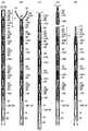
次に、図7〜12を参照して、操作ワイヤを操作する操作部について説明する。
図7は、操作部の概略構成を示す断面図である。同図に示す操作部120は、図中左側が、クリップ12およびシース16と接続され、図中右側が、操作者によって操作される。以下の説明では、図7における左側の端部を先端、右側の端部を基端と呼ぶ。
Next, with reference to FIGS. 7-12, the operation part which operates an operation wire is demonstrated.
FIG. 7 is a cross-sectional view illustrating a schematic configuration of the operation unit. Theoperation unit 120 shown in the figure is connected to theclip 12 and thesheath 16 on the left side in the figure, and is operated by the operator on the right side in the figure. In the following description, the left end in FIG. 7 is referred to as the distal end, and the right end is referred to as the proximal end.

操作部120は、その中心を成す本体レール122と、本体レール122の先端に固定された先端部材124と、本体レール122の基端に取り付けられた指掛けリング126と、本体レール122の外側に設けられたワイヤ固定部材128、調整ダイヤル130、スライダ132、およびロックダイヤル134と、先端部材124の外側に設けられたスライダガイド138、および位置規制機構142とを有している。  Theoperation unit 120 is provided on the outer side of themain body rail 122, amain body rail 122 that forms the center, atip member 124 that is fixed to the front end of themain body rail 122, afinger hook ring 126 that is attached to the base end of themain body rail 122. Thewire fixing member 128, theadjustment dial 130, theslider 132, and thelock dial 134, theslider guide 138 provided on the outer side of thetip member 124, and theposition restriction mechanism 142.

シース16(縮径部48)の基端は、先端部材124の先端に保持され、操作ワイヤ20の基端は、ワイヤ固定部材128のワイヤ接続部128aに保持される。操作者は、例えば、指掛けリング126に親指を掛け、スライダ132に人差し指と中指を掛けて、スライダ132を指掛けリング126に対して進退方向にスライド移動させることができる。スライダ132が移動すると、ワイヤ固定部材128も共に移動し、ワイヤ接続部128aに保持された操作ワイヤ20も共に移動する。一方、シース16は、先端部材124および本体レール122を介して指掛けリング126に接続している。したがって、指掛けリング126に対するスライダ132の移動操作によって、シース16に対して操作ワイヤ20を進退移動させることができる。以下、操作部120の各部の構成について詳述する。  The proximal end of the sheath 16 (reduced diameter portion 48) is held at the distal end of thedistal end member 124, and the proximal end of theoperation wire 20 is held at thewire connecting portion 128a of thewire fixing member 128. For example, the operator can place his / her thumb on thefinger ring 126, his / her index finger and middle finger on theslider 132, and slide theslider 132 in the forward / backward direction with respect to thefinger ring 126. When theslider 132 moves, thewire fixing member 128 also moves, and theoperation wire 20 held by thewire connecting portion 128a also moves. On the other hand, thesheath 16 is connected to thefinger ring 126 via thetip member 124 and themain body rail 122. Therefore, theoperation wire 20 can be moved back and forth with respect to thesheath 16 by the movement operation of theslider 132 with respect to thefinger ring 126. Hereinafter, the configuration of each unit of theoperation unit 120 will be described in detail.

本体レール122は、図8に示すように、円柱状の基端部122aから、断面が略半円状の2つの棒部材122b,122bが延びた形状を有している。2つの棒部材122b,122bは、平面部を対向させて、その間に所定の間隔を空けて配置されており、両部材の曲面は、1つの円筒面を形成している。言い換えれば、棒部材122b,122bは、基端部122aと同軸でそれよりも細い円柱の中央を、その軸線に沿って所定幅で削り落とした形状である。図7では、本体レール122は、図中手前側の棒部材122bが取り除かれ、奥側の棒部材122bの平面部が表示されている。  As shown in FIG. 8, themain body rail 122 has a shape in which tworod members 122b and 122b having a substantially semicircular cross section extend from a cylindricalbase end portion 122a. The tworod members 122b and 122b are arranged with a predetermined interval therebetween with the plane portions facing each other, and the curved surfaces of both members form one cylindrical surface. In other words, therod members 122b and 122b have a shape in which the center of a cylinder that is coaxial with thebase end portion 122a and thinner than that is scraped off with a predetermined width along the axis. In FIG. 7, themain body rail 122 has thebar member 122b on the near side in the drawing removed, and the flat portion of thebar member 122b on the back side is displayed.

2つの棒部材122b,122bの間隔は、ワイヤ固定部材128のワイヤ接続部128a、および、スライダ132に取り付けられるスライダピン136の先端部分が挿入可能な寸法とされている。図7に示すように、ワイヤ接続部128aおよびスライダピン136は、先端が2つの棒部材122b,122bの間に挿入され、棒部材122b,122bにガイドされて、本体レール122の延在方向に移動できる。すなわち、本体レール122は、棒部材122b,122bが、ワイヤ接続部128a(ワイヤ固定部材128)およびスライダピン136(スライダ132)のレールとして機能する。  The distance between the tworod members 122b and 122b is such that thewire connecting portion 128a of thewire fixing member 128 and the tip of theslider pin 136 attached to theslider 132 can be inserted. As shown in FIG. 7, thewire connection portion 128 a and theslider pin 136 are inserted between the tworod members 122 b and 122 b and guided by therod members 122 b and 122 b in the extending direction of themain body rail 122. Can move. That is, in themain body rail 122, therod members 122b and 122b function as rails for thewire connecting portion 128a (wire fixing member 128) and the slider pin 136 (slider 132).

先端部材124は、基端部に径が大きいフランジ状の部分124aを持つ円筒状の部品である。先端部材124の基端の端面には、本体レール122の先端が固定されている。また、先端部材124の先端には、シース16の基端部が挿入されて保持されている。操作ワイヤ20は、シース16の基端から延びて先端部材124の内部の空間を貫通している。先端部材124の筒状部分の外径は、先端部材124の外側に配置されるスライダガイド138の先端部分の内径にほぼ等しく、フランジ状部分124aの外径は、スライダガイド138の後端側の内径にほぼ等しい。これにより、スライダガイド138が先端部材124に対して摺動可能となっている。  Thedistal end member 124 is a cylindrical part having a flange-shaped portion 124a having a large diameter at the proximal end portion. The distal end of thebody rail 122 is fixed to the end surface of the proximal end of thedistal end member 124. The proximal end portion of thesheath 16 is inserted and held at the distal end of thedistal end member 124. Theoperation wire 20 extends from the proximal end of thesheath 16 and penetrates the space inside thedistal end member 124. The outer diameter of the cylindrical portion of thetip member 124 is substantially equal to the inner diameter of the tip portion of theslider guide 138 disposed outside thetip member 124, and the outer diameter of the flange-like portion 124 a is on the rear end side of theslider guide 138. It is almost equal to the inner diameter. As a result, theslider guide 138 can slide with respect to thetip member 124.

指掛けリング126は、操作者が指を挿入可能なリング部分を持つ部品で、本体レール122の円筒状の基端部122aに取り付けられている。  Thefinger ring 126 is a part having a ring portion through which an operator can insert a finger, and is attached to the cylindricalbase end portion 122 a of themain body rail 122.

ワイヤ固定部材128は、本体レール122の2つの棒部材122b,122bの外径とほぼ等しい内径を有する円筒状の部材である。ワイヤ固定部材128の基端部分の外周面にはネジが切ってある。ワイヤ固定部材128の軸方向の略中央部には、内面側へ突出するワイヤ接続部128aが形成されている。先端部材124を貫通して延びる操作ワイヤ20の基端は、ワイヤ接続部128aの、ワイヤ固定部材128の中心軸(すなわち操作部120の中心軸)に一致する位置に固定される。なお、操作ワイヤ20は、シース16の先端内部からワイヤ接続部128aの範囲までが、補強管148によって覆われており、操作部120の内部で折れることがないように補強されている。  Thewire fixing member 128 is a cylindrical member having an inner diameter substantially equal to the outer diameter of the tworod members 122b and 122b of themain body rail 122. A screw is cut on the outer peripheral surface of the proximal end portion of thewire fixing member 128. Awire connecting portion 128 a that protrudes toward the inner surface is formed at a substantially central portion in the axial direction of thewire fixing member 128. The proximal end of theoperation wire 20 extending through thedistal end member 124 is fixed at a position corresponding to the central axis of the wire fixing member 128 (that is, the central axis of the operation unit 120) of thewire connecting portion 128a. Theoperation wire 20 is covered with a reinforcingpipe 148 from the inside of the distal end of thesheath 16 to the range of thewire connection portion 128a, and is reinforced so as not to be broken inside theoperation portion 120.

調整ダイヤル130は、ワイヤ固定部材128の外側に嵌められたフランジ付きの円筒状部品である。調整ダイヤル130の基端側の内周面にはネジが切ってあり、このネジ部分が、ワイヤ固定部材128のネジ部分に嵌められている。調整ダイヤル130は、フランジ部分が操作者によって回されることで、その回転方向に応じて、ワイヤ固定部材128のネジに沿って前進または後退する。調整ダイヤル130の薄肉部分の外周面には、スライダ132の凹部と係合する凸部が、全周にわたって設けられている。  Theadjustment dial 130 is a cylindrical part with a flange fitted to the outside of thewire fixing member 128. A screw is cut on the inner peripheral surface of the base end side of theadjustment dial 130, and this screw portion is fitted to the screw portion of thewire fixing member 128. Theadjustment dial 130 is advanced or retracted along the screw of thewire fixing member 128 according to the rotation direction by turning the flange portion by the operator. On the outer peripheral surface of the thin portion of theadjustment dial 130, a convex portion that engages with the concave portion of theslider 132 is provided over the entire circumference.

スライダ132は、糸巻き状の形状を有しており、操作者が指を掛けて進退方向に動かし易いようになっている。スライダ132には、ワイヤ固定部材128が挿通されている。また、スライダ132の基端側部分は内径が大きくなっており、基端側から調整ダイヤル130が挿入されている。スライダ132の内周面には、調整ダイヤル130の凸部と係合する凹部が全周に形成されている。この凹部と凸部の係合により、軸方向には、スライダ132は調整ダイヤル130と一体的に移動するが、周方向には、調整ダイヤル130とスライダ132とは回転自在となっている。  Theslider 132 has a pincushion shape so that the operator can easily move it in the forward / backward direction with his / her finger. Awire fixing member 128 is inserted through theslider 132. Further, the base end side portion of theslider 132 has a large inner diameter, and theadjustment dial 130 is inserted from the base end side. A concave portion that engages with the convex portion of theadjustment dial 130 is formed on the entire inner circumferential surface of theslider 132. Due to the engagement between the concave portion and the convex portion, theslider 132 moves integrally with theadjustment dial 130 in the axial direction, but theadjustment dial 130 and theslider 132 are rotatable in the circumferential direction.

ロックダイヤル134は、内周面にワイヤ固定部材128の基端部のネジに対応するネジが切られた、リング状の部品である。調整ダイヤル130の位置が調整された後に、ロックダイヤル134を調整ダイヤル130の基端の端面に当たるまでネジが締められることで、調整後の調整ダイヤル130の位置がロックされる。  Thelock dial 134 is a ring-shaped component in which a screw corresponding to the screw at the proximal end of thewire fixing member 128 is cut on the inner peripheral surface. After the position of theadjustment dial 130 is adjusted, the screw is tightened until thelock dial 134 comes into contact with the end face of the base end of theadjustment dial 130, thereby locking the position of the adjustedadjustment dial 130.

スライダ132と調整ダイヤル130とは、凹部と凸部によって係合し、調整ダイヤル130およびロックダイヤル134とワイヤ固定部材128とは、ネジ部分によって係合しているので、スライダ132が進退方向(図中左右方向)へ動かされると、これらの4つの部品が一体的に移動する。  Theslider 132 and theadjustment dial 130 are engaged by a concave portion and a convex portion, and theadjustment dial 130, thelock dial 134, and thewire fixing member 128 are engaged by a screw portion. When these are moved in the middle and left and right directions), these four parts move together.

スライダピン136は、スライダ132の先端部分に、外側から内側へ差し込んで固定されている。スライダピン136は、その先端が、本体レール122の棒部材122b,122bの間に達しており、2つの棒部材122b,122bの間を移動できる。  Theslider pin 136 is inserted and fixed to the tip portion of theslider 132 from the outside to the inside. The tip of theslider pin 136 reaches between thebar members 122b and 122b of themain body rail 122, and can move between the twobar members 122b and 122b.

スライダガイド138は、先端部材124の外側に設けられた略円筒状の部材である。上述したように、スライダガイド138の先端部分の内径は、先端部材124の筒状部分の外径とほぼ等しく、スライダガイド138の基端側の内径は、先端部材124のフランジ部分124aの外径とほぼ等しく、スライダガイド138は、フランジ状の部分124aに摺動可能に支持されている。また、スライダガイド138の基端側部分の外径は、スライダ132の内径よりわずかに小さく、スライダ132が先端側へ移動したときに、スライダ132の内側へ入り込むことができる。スライダガイド138は、操作者の操作によって、その先端の位置規制機構142に対して回転移動するため、操作者が持ちやすいように、外面に傾斜面が形成されている。  Theslider guide 138 is a substantially cylindrical member provided outside thetip member 124. As described above, the inner diameter of the distal end portion of theslider guide 138 is substantially equal to the outer diameter of the cylindrical portion of thedistal end member 124, and the inner diameter of theslider guide 138 on the proximal end side is the outer diameter of the flange portion 124a of thedistal end member 124. Theslider guide 138 is slidably supported by the flange-shaped portion 124a. Further, the outer diameter of the proximal end portion of theslider guide 138 is slightly smaller than the inner diameter of theslider 132, and can enter the inside of theslider 132 when theslider 132 moves to the distal end side. Theslider guide 138 is rotationally moved with respect to theposition restricting mechanism 142 at the tip of theslider guide 138 by an operation of the operator, and thus an inclined surface is formed on the outer surface so that the operator can easily hold it.

先端部材124のフランジ部分124aとスライダガイド138の内面との間には、先端部材124を中心としてコイルバネ144が配置されている。コイルバネ144は、圧縮バネであり、固定部材である先端部材124(そのフランジ部分124a)に対して、スライダガイド138を先端側へ付勢して、位置規制機構142の方へ押し付けている。位置規制機構142は、先端部材124に固定されている。  Acoil spring 144 is disposed between the flange portion 124 a of thetip member 124 and the inner surface of theslider guide 138 with thetip member 124 as the center. Thecoil spring 144 is a compression spring, and urges theslider guide 138 toward the distal end side against the distal end member 124 (the flange portion 124a), which is a fixed member, and presses theslider guide 138 toward theposition regulating mechanism 142. Theposition regulating mechanism 142 is fixed to thetip member 124.

図9および図10を参照して、スライダガイド138および位置規制機構142についてさらに詳細に説明する。図9(A)は、スライダガイド138の斜視図であり、図9(B)は、スライダガイド138の基端側のガイド溝部分の展開図である。また、図10は、位置規制機構142の斜視図である。  With reference to FIGS. 9 and 10, theslider guide 138 and theposition regulating mechanism 142 will be described in more detail. FIG. 9A is a perspective view of theslider guide 138, and FIG. 9B is a development view of the guide groove portion on the proximal end side of theslider guide 138. FIG. 10 is a perspective view of theposition regulating mechanism 142.

図9(A)に示すように、スライダガイド138の先端部の、位置規制機構142との接合部138aには、その端面に、周方向において2辺の傾斜角が異なる鋸波形状の凸部が90度間隔で4つ形成されている。この鋸波形状の凸部は、一方の面の傾斜角が緩やかで、他方の面の傾斜角が略直角である。また、図10に示すように、位置規制機構142の後端部の、スライダガイド138との接合部142aにも、スライダガイド138の接合部138aの凸部と同様の4つの凸部が設けられている。  As shown in FIG. 9A, thejoint portion 138a of the end portion of theslider guide 138 with theposition restricting mechanism 142 has a sawtooth-shaped convex portion with two inclined angles different in the circumferential direction on the end surface. Are formed at intervals of 90 degrees. The sawtooth-shaped convex portion has a gentle inclination angle on one surface and a substantially right angle on the other surface. Also, as shown in FIG. 10, the four convex portions similar to the convex portions of thejoint portion 138 a of theslider guide 138 are also provided on thejoint portion 142 a of the rear end portion of theposition regulating mechanism 142 with theslider guide 138. ing.

スライダガイド138は、位置規制機構142と噛み合った状態でコイルバネ144によって位置規制機構142に押し付けられているため、操作者からの外力が作用しない限り、スライダガイド138は位置規制機構142に対して回転しない。また、位置規制機構142とスライダガイド138とは、鋸波形状の凹凸で噛み合っているので、操作者がスライダガイド138を軸周りに回そうとした場合に、スライダガイド138は、その接合部138aおよび142aの凸部の、互いの急斜面(略直角面)が離れる方向には回転するが、その反対の急斜面が当接する方向へは回転しない。図示例では、スライダガイド138は、基端側(図9(A)の右側)から見て反時計方向には回転できるが、時計方向には回転できない。  Since theslider guide 138 is pressed against theposition restricting mechanism 142 by thecoil spring 144 while being engaged with theposition restricting mechanism 142, theslider guide 138 rotates with respect to theposition restricting mechanism 142 unless an external force is applied from the operator. do not do. Further, since theposition restricting mechanism 142 and theslider guide 138 are engaged with each other by saw-tooth irregularities, when the operator tries to turn theslider guide 138 around the axis, theslider guide 138 has its joint 138a. And the convex portions of 142a rotate in the direction in which the steep slopes (substantially right-angled surfaces) are separated from each other, but do not rotate in the direction in which the opposite steep slopes abut. In the illustrated example, theslider guide 138 can rotate counterclockwise when viewed from the base end side (the right side in FIG. 9A), but cannot rotate clockwise.

スライダガイド138は、接合部138aの緩斜面が位置規制機構142の接合部142aの緩斜面に沿って回転し、90度回転して互いの頂点を乗り越えると、次の凹凸で噛み合う。それにより、スライダガイド138は、90度ずつ回転する。  When the gentle slope of thejoint portion 138a rotates along the gentle slope of thejoint portion 142a of theposition regulating mechanism 142 and theslider guide 138 rotates 90 degrees and overcomes the top of each other, theslider guide 138 meshes with the next unevenness. Thereby, theslider guide 138 rotates by 90 degrees.

スライダガイド138の基端側の円筒部分には、図9(A)に示すように、基端側端面から回転軸に沿って延在する4本のスライダガイド溝140A,140B,140C,140Dが、90度間隔で形成されている。このスライダガイド溝140A〜140Dは、図9(B)に示すように、それぞれ溝の長さが異なる。図示例では、スライダガイド溝140Aが最も長く、スライダガイド溝140D、スライダガイド溝140C、スライダガイド溝140Bの順で短くなっている。図7では、図中上側に、最も短いスライダガイド溝140Bが、下側に2番目に長いスライダガイド溝140Dが表れている。  As shown in FIG. 9A, fourslider guide grooves 140A, 140B, 140C, and 140D extending along the rotation axis from the proximal end surface are formed in the cylindrical portion on the proximal end side of theslider guide 138. , Formed at intervals of 90 degrees. As shown in FIG. 9B, theslider guide grooves 140A to 140D have different groove lengths. In the illustrated example, theslider guide groove 140A is the longest, and theslider guide groove 140D, theslider guide groove 140C, and theslider guide groove 140B become shorter in this order. In FIG. 7, the shortestslider guide groove 140B appears on the upper side in the drawing, and the second longestslider guide groove 140D appears on the lower side.

スライダガイド溝140A〜140Dは、スライダピン136のガイド溝としての機能を有し、その溝の幅は、スライダピン136の径とほぼ等しい。スライダガイド138が90度回転するごとに、スライダガイド溝140A〜140Dの何れかが、本体レール122のレール位置、すなわち2つの棒部材122b,122bの間の位置に一致するように配置される。したがって、操作者の操作によってスライダ132が進退方向に移動するときは、スライダピン136は、先端部分が本体レール122に案内されると同時に、中間部分がスライダガイド溝140A〜140Dの何れかに案内され、スライダ132の移動量は、スライダガイド溝140A〜140Dの溝の長さによって定められる。  Theslider guide grooves 140 </ b> A to 140 </ b> D have a function as a guide groove for theslider pin 136, and the width of the groove is substantially equal to the diameter of theslider pin 136. Each time theslider guide 138 rotates 90 degrees, any one of theslider guide grooves 140A to 140D is arranged so as to coincide with the rail position of themain body rail 122, that is, the position between the tworod members 122b and 122b. Therefore, when theslider 132 moves in the forward / backward direction by the operation of the operator, theslider pin 136 is guided to themain body rail 122 at the tip portion and at the same time, the middle portion is guided to any of theslider guide grooves 140A to 140D. The amount of movement of theslider 132 is determined by the length of theslider guide grooves 140A to 140D.

すなわち、スライダガイド138は、スライダガイド溝140A〜140Dにより、本体レール122に沿って移動するスライダピン136の先端側への移動限界を規定することで、スライダ132、およびそれと共に移動する調整ダイヤル130、ワイヤ固定部材128、ロックダイヤル134の移動位置を規定して、ワイヤ固定部材128に接続された操作ワイヤ20の移動位置を規定する。  That is, theslider guide 138 regulates the limit of movement of theslider pin 136 moving along themain body rail 122 by theslider guide grooves 140 </ b> A to 140 </ b> D, thereby adjusting theslider 132 and theadjustment dial 130 moving together therewith. The movement positions of thewire fixing member 128 and thelock dial 134 are defined, and the movement position of theoperation wire 20 connected to thewire fixing member 128 is defined.

スライダ132等の基端側の移動限界は、ロックダイヤル134の基端側端面が、本体レール122の基端部122aの先端側端面に当接する位置によって規定される。  The movement limit on the base end side of theslider 132 or the like is defined by the position where the base end side end surface of the lock dial 134 contacts the front end side end surface of thebase end portion 122 a of themain body rail 122.

図11および図12を参照して、操作部120の作用を説明する。
図11は、クリップ処置動作時のスライダガイド138とスライダピン136との位置関係を示す、スライダガイド溝140A〜140Dの部分の展開図である。図12はクリップ処置動作における段階的な状態を示す部分断面図である。スライダ132等が、基端側の移動限界にあるときのスライダピン136の位置を、ホームポジションP1とする。スライダ132のホームポジションは、スライダ132が最も基端側まで引かれたときの位置であり、ロックダイヤル134が本体レール122の基端部122aに当接することで規定される。スライダピン136が、ホームポジションP1にあるとき、操作ワイヤ20の先端は、3つのクリップ12とダミークリップ18および接続部材19の分L1だけ、シース16の先端から引っ込んだ位置にある(図12(A)参照)。
The operation of theoperation unit 120 will be described with reference to FIGS. 11 and 12.
FIG. 11 is a development view of portions of theslider guide grooves 140A to 140D showing the positional relationship between theslider guide 138 and theslider pin 136 during the clip treatment operation. FIG. 12 is a partial cross-sectional view showing a stepped state in the clip treatment operation. The position of theslider pin 136 when theslider 132 or the like is at the movement limit on the proximal end side is defined as a home position P1. The home position of theslider 132 is a position when theslider 132 is pulled to the most proximal end side, and is defined by thelock dial 134 coming into contact with theproximal end portion 122 a of themain body rail 122. When theslider pin 136 is at the home position P1, the distal end of theoperation wire 20 is in a position retracted from the distal end of thesheath 16 by the amount L1 of the threeclips 12, thedummy clip 18, and the connecting member 19 (FIG. 12 ( A)).

図7の操作部120において、まず、スライダガイド138を回して、スライダガイド溝140Aがスライダピン136に一致する位置にセットする。次いで、スライダ132を前方へ移動させて、スライダピン136をスライダガイド溝140Aの先端の最大突出位置P2まで移動させると、スライダガイド溝140Aの溝の長さに等しい長さL1だけ操作ワイヤ20が先端側へ移動し、操作ワイヤ20の先端がシース16の先端から突出して、操作ワイヤ20に、接続部材19を取り付けられるようになる(図12(B)参照)。接続部材19を操作ワイヤ20に取り付けた後、スライダ132を後方へ移動させて、スライダピン136をホームポジションP1と同じ位置であるP3に戻すと、操作ワイヤ20がシース16の内部に引き込まれることによって、操作ワイヤ20の先端に接続された接続部材19、ダミークリップ18およびそれに続く3つのクリップ12がシース16内に引き込まれる(図12(C)参照)。これにより、シース16へのクリップの装填が完了する。  In theoperation unit 120 of FIG. 7, first, theslider guide 138 is rotated to set theslider guide groove 140 </ b> A at a position that coincides with theslider pin 136. Next, when theslider 132 is moved forward and theslider pin 136 is moved to the maximum protruding position P2 at the tip of theslider guide groove 140A, theoperation wire 20 is moved by a length L1 equal to the length of theslider guide groove 140A. The distal end of theoperation wire 20 protrudes from the distal end of thesheath 16 so that theconnection member 19 can be attached to the operation wire 20 (see FIG. 12B). After the connectingmember 19 is attached to theoperation wire 20, theslider 132 is moved backward to return theslider pin 136 to P3 which is the same position as the home position P1, and theoperation wire 20 is drawn into thesheath 16. As a result, theconnection member 19, thedummy clip 18, and the threesubsequent clips 12 connected to the distal end of theoperation wire 20 are drawn into the sheath 16 (see FIG. 12C). Thereby, the loading of the clip into thesheath 16 is completed.

次に、スライダガイド138を90度回転させる。これにより、スライダピン136の位置が、ホームポジションP1およびP3と軸方向の位置が等しく周方向の位置が90度異なる位置P4となり、スライダピン136がスライダガイド溝140Bの位置に一致する。スライダ132を前方へ移動させて、スライダピン136をスライダガイド溝140Bの先端の突出位置P5まで移動させると、スライダガイド溝140Bの溝の長さだけ、操作ワイヤ20およびそれに接続されたクリップ12等が、先端側へ移動する(図12(D)参照)。  Next, theslider guide 138 is rotated 90 degrees. As a result, the position of theslider pin 136 becomes the position P4 where the position in the axial direction is the same as the home positions P1 and P3 and the position in the circumferential direction is different by 90 degrees, and theslider pin 136 coincides with the position of theslider guide groove 140B. When theslider 132 is moved forward and theslider pin 136 is moved to the projecting position P5 at the tip of theslider guide groove 140B, theoperation wire 20 and theclip 12 connected to theoperation wire 20 and the like are as long as the length of theslider guide groove 140B. Moves to the tip side (see FIG. 12D).

ここで、スライダガイド溝140Bの長さは、先頭のクリップ12がシース16の先端から突出し、その連結リング14のスカート部38が開くまでの操作ワイヤ20の移動量L2に一致させてある。したがって、スライダピン136が突出位置P5に来るまでスライダ132を移動させることで、先頭のクリップ12を使用可能な状態(スタンバイ状態)とすることができる。  Here, the length of theslider guide groove 140B is made to coincide with the amount of movement L2 of theoperation wire 20 until the leadingclip 12 protrudes from the distal end of thesheath 16 and theskirt portion 38 of the connectingring 14 opens. Therefore, by moving theslider 132 until theslider pin 136 reaches the protruding position P5, the leadingclip 12 can be used (standby state).

続いて、スライダ132を後方へ移動させると、スライダピン136がクリップ完了位置P6に移動した時点で、シース16の先端の処置動作部では、先頭のクリップ12の連結リング14による締め付け(図12(E)参照)、および次のクリップ12との切り離しが行われる(図12(F)参照)。これにより、1発目のクリップ処置が完了する。  Subsequently, when theslider 132 is moved rearward, when theslider pin 136 moves to the clip completion position P6, the treatment operation portion at the distal end of thesheath 16 is tightened by theconnection ring 14 of the leading clip 12 (FIG. 12 ( E)), and thenext clip 12 is separated (see FIG. 12F). This completes the first clipping procedure.

引き続きスライダ132を後方へ移動させて、スライダピン136をホームポジションP4と同じ位置P7に戻し、次のクリップ処置のために、スライダガイド138を先ほどと同方向へ90度回転させて、スライダピン136をスライダガイド溝140CのホームポジションP8に一致させる(図12(G)参照)。スライダピン136がホームポジションP8にあるとき(図12(G)参照)の操作ワイヤ20の先端の位置は、スライダピン136がP3にあるとき(図12(C)参照)の操作ワイヤ20の先端の位置と同じになっている。  Subsequently, theslider 132 is moved rearward, theslider pin 136 is returned to the same position P7 as the home position P4, and theslider guide 138 is rotated 90 degrees in the same direction as before to perform the next clip treatment. Is made to coincide with the home position P8 of theslider guide groove 140C (see FIG. 12G). The position of the tip of theoperation wire 20 when theslider pin 136 is at the home position P8 (see FIG. 12G) is the tip of theoperation wire 20 when theslider pin 136 is at P3 (see FIG. 12C). The position is the same.

スライダガイド溝140C、140Dは、それぞれ、2番目、3番目のクリップ12をシース16から突出させるための操作ワイヤ20の移動量に一致させてある。以下、1発目と同様にして、スライダ132の前方への移動、後方への移動、スライダガイド138の90度回転を順に行うことで、2発目、3発目のクリップ処置を行うことができる。  Theslider guide grooves 140 </ b> C and 140 </ b> D are respectively matched with the movement amount of theoperation wire 20 for causing the second andthird clips 12 to protrude from thesheath 16. Thereafter, in the same manner as the first shot, the second and third clip treatments can be performed by sequentially moving theslider 132 forward, moving backward, and rotating theslider guide 138 by 90 degrees. it can.

ここで、スライダガイド138は3連発用であるが、スライドガイド溝を増減することで他の連発数のクリップ処置具へも適用可能である。例えば、5連発用とするためにはスライドガイド溝を2本増加させ、スライドガイド溝の間隔を60度とすることで、5発のクリップ処置を連続して行うことができる。  Here, theslider guide 138 is for triple firing, but it can also be applied to other number of continuous clip treatment instruments by increasing or decreasing the slide guide groove. For example, in order to use five times, the number of slide guide grooves is increased by two, and the interval between the slide guide grooves is set to 60 degrees, so that five clip treatments can be performed continuously.

長期間の使用のうちに、操作ワイヤ20が伸びてしまった場合には、以下のように調整する。まずロックダイヤル134を緩め、次いで調整ダイヤル130を回して、調整ダイヤル130をワイヤ固定部材128に対して先端側へ移動させる。スライダ132は、調整ダイヤル130の凸部と係合しているので、軸方向へはスライダ132と一緒に移動する。ただし、調整ダイヤル130とスライダ132は、回転方向の移動はフリーなので、スライダピン136によって周方向の移動が規制されたスライダ132に対し、調整ダイヤル130だけが回転することができる。操作ワイヤ20の弛みが無くなる分だけ調整ダイヤル130を移動させたら、再びロックダイヤル134を締めて調整ダイヤル130およびスライダ132の位置をロックする。  When theoperation wire 20 is extended during long-term use, the following adjustment is performed. First, thelock dial 134 is loosened, and then theadjustment dial 130 is turned to move theadjustment dial 130 toward the distal end side with respect to thewire fixing member 128. Since theslider 132 is engaged with the convex portion of theadjustment dial 130, theslider 132 moves together with theslider 132 in the axial direction. However, since theadjustment dial 130 and theslider 132 are free to move in the rotation direction, only theadjustment dial 130 can rotate with respect to theslider 132 whose movement in the circumferential direction is restricted by theslider pin 136. When theadjustment dial 130 is moved by an amount corresponding to the loosening of theoperation wire 20, thelock dial 134 is tightened again to lock the positions of theadjustment dial 130 and theslider 132.

スライダ132のホームポジションは、ロックダイヤル134が本体レール122の基端部122aに当接することで規定されるので、ホームポジションにおけるスライダ132の本体レール122に対する位置は変わらない。一方、調整ダイヤル130およびスライダ132をワイヤ固定部材128に対して先端側に移動させることにより、ワイヤ固定部材128がスライダ132に対して相対的に後方へ移動することになり、ワイヤ接続部128aも同様に移動する。したがって、ホームポジションにおける操作ワイヤ20の基端が後方へ移動することとなり、操作ワイヤ20の伸び分による弛みを解消することができる。  Since the home position of theslider 132 is defined by thelock dial 134 coming into contact with thebase end portion 122a of themain body rail 122, the position of theslider 132 relative to themain body rail 122 at the home position does not change. On the other hand, by moving theadjustment dial 130 and theslider 132 toward the distal end side with respect to thewire fixing member 128, thewire fixing member 128 is moved rearward relative to theslider 132, and thewire connecting portion 128a is also connected. Move in the same way. Accordingly, the proximal end of theoperation wire 20 at the home position moves backward, and the slack due to the extension of theoperation wire 20 can be eliminated.

また、本発明のクリップ処置具10では、上述したように、連結リング14でクリップ12の連結部分を覆って保持するため、複数のクリップ12の連結状態が確実に維持される。そして、操作ワイヤ20でダミークリップ18およびそれに連結する複数のクリップ12を所定長分だけ一方向に牽引することで、連結リング14の締付部40による先頭のクリップ12の締め付けと、次のクリップ12との連結解除とを同時に行って、先頭のクリップ12によるクリップ処置を行うことができ、さらに、操作ワイヤ20を先端側へ所定長分移動させることで、次のクリップ12が使用可能となり、続けてクリップ処置を行うことができる。  Moreover, in theclip treatment tool 10 of this invention, since the connection part of theclip 12 is covered and hold | maintained with theconnection ring 14 as mentioned above, the connection state of the someclip 12 is maintained reliably. Then, theoperation clip 20 pulls thedummy clip 18 and the plurality ofclips 12 connected to thedummy clip 18 in one direction by a predetermined length, whereby the leadingclip 12 is tightened by the tighteningportion 40 of the connectingring 14 and the next clip. Theclip 12 can be clipped with the leadingclip 12 at the same time, and thenext clip 12 can be used by moving theoperation wire 20 to the distal end side by a predetermined length. The clip treatment can be performed subsequently.

また、クリップ12の連結部を連結リング14で覆っているため、クリップ処置操作時等にクリップ12の連結部の角部などでシース16の内壁を傷付ける心配が無く、シース16を内視鏡に挿入する時などにも、連結部において、クリップ12にこじれや歪みを生じる可能性が極めて小さい。  Further, since the connecting portion of theclip 12 is covered with the connectingring 14, there is no fear of damaging the inner wall of thesheath 16 at the corner portion of the connecting portion of theclip 12 at the time of a clip treatment operation or the like, and thesheath 16 is used as an endoscope. The possibility of twisting and distortion of theclip 12 at the connecting portion is extremely small even when the connector is inserted.

次に、本発明の連発式クリップ処置具に用いられる操作部の他の例について説明する。上記の実施形態では、先頭のクリップ12をシース16から突出させるときには、操作部120のスライダ132によって操作ワイヤ20を押し出し、また、クリップ12による処置をするときには、操作部120のスライダ132によってクリップ12に接続する操作ワイヤ20を手元側へ引いて、シース16に対して操作ワイヤ20の進退操作のみでクリップ12を進退移動させた。しかし、操作部の構成およびクリップ処置具の動作は、これには限定されず、シース16と操作ワイヤ20をそれぞれ操作して、クリップ12とシース16とを相対的に移動させて、クリップ12をシース16から突出させることと、クリップ処置とを行ってもよい。  Next, another example of the operation unit used in the continuous clip treatment tool of the present invention will be described. In the above-described embodiment, when the leadingclip 12 protrudes from thesheath 16, theoperation wire 20 is pushed out by theslider 132 of theoperation unit 120, and when the treatment with theclip 12 is performed, theclip 12 is operated by theslider 132 of theoperation unit 120. Theoperation wire 20 to be connected to is pulled to the proximal side, and theclip 12 is moved forward and backward only by the advancement and retraction operation of theoperation wire 20 with respect to thesheath 16. However, the configuration of the operation unit and the operation of the clip treatment tool are not limited to this, and theclip 12 and thesheath 16 are moved relative to each other by operating thesheath 16 and theoperation wire 20, respectively. Protruding from thesheath 16 and clip treatment may be performed.

図14(A)および(B)は操作部の他の例の概略構成を示す部分断面平面図および部分断面正面図である。同図に示す操作部50は5連発のクリップ処置具に用いることができ、上述の実施形態のクリップ処置具10において、クリップ12を5つ装填して5連発で使用可能な処置具とした場合に、操作部120に代えて用いることができる。操作部50を用いた場合でも、クリップ処置動作等における、クリップ装填部分(シース16の先端部分)の各部の相対的な位置関係は上述の各例と同様であり、また、シース16に縮径部48を設けたことによる作用効果は、上述の例と同様である。  14A and 14B are a partial cross-sectional plan view and a partial cross-sectional front view showing a schematic configuration of another example of the operation unit. Theoperation unit 50 shown in the figure can be used for a five-shot clip treatment tool. In theclip treatment tool 10 of the above-described embodiment, when five clips 12 are loaded and the treatment tool can be used for five-shot operation. In addition, theoperation unit 120 can be used instead. Even in the case where theoperation unit 50 is used, the relative positional relationship of each part of the clip loading portion (the distal end portion of the sheath 16) in the clip treatment operation or the like is the same as that in each of the above-described examples. The effect by providing thepart 48 is the same as that of the above-mentioned example.

図14(A)および(B)において、操作部50は、左側が、クリップ12に連結された操作ワイヤ20およびクリップ12を収納するシース16と接続される先端側、右側が、操作者によって操作される後端側(または基端側)であり、操作部本体であるワイヤ操作ハンドル52と、シース16(縮径部48)の基端部を把持する把持部の機能を持つシース操作ハンドル54とを有している。シース操作ハンドル54は、ワイヤ操作ハンドル52に対してスライド移動可能に構成されている。  14A and 14B, theoperation unit 50 is operated by the operator on the left side on the distal end side connected to theoperation wire 20 coupled to theclip 12 and thesheath 16 that houses theclip 12, and on the right side. The wire operation handle 52 which is the rear end side (or the base end side) and is the operation portion main body and the sheath operation handle 54 having the function of a gripping portion for gripping the base end portion of the sheath 16 (the reduced diameter portion 48). And have. The sheath operation handle 54 is configured to be slidable with respect to the wire operation handle 52.

ワイヤ操作ハンドル52は、円筒状のケース58と、ケース58の先端に軸を一致させて固定された位置決めパイプ56と、ケース58の内部に保持されたレバー60およびスプリング62とを有している。
レバー60は、ケース58の内部において、前後方向(ワイヤ操作ハンドル52の軸方向)に移動可能に保持されている。レバー60の後端側の一部は、ケース58の中央部分に設けられた貫通窓59に現れており、操作者が指を掛けてレバー60を後端側に引けるようになっている。レバー60の後端にはスプリング62が取り付けられている。スプリング62は、レバー60が後方へ引かれることによって圧縮され、レバー60を引く力が解除されると、反発力によってレバー60を前方へ押し戻す。それにより、レバー60は元の位置(ホームポジション)へ戻る。
The wire operation handle 52 includes acylindrical case 58, apositioning pipe 56 that is fixed to the tip of thecase 58 with its axis aligned, and alever 60 and aspring 62 that are held inside thecase 58. .
Thelever 60 is held inside thecase 58 so as to be movable in the front-rear direction (the axial direction of the wire operation handle 52). A part of the rear end side of thelever 60 appears in a throughwindow 59 provided in the central portion of thecase 58 so that the operator can pull thelever 60 toward the rear end side by placing a finger. Aspring 62 is attached to the rear end of thelever 60. Thespring 62 is compressed by pulling thelever 60 backward, and when the force pulling thelever 60 is released, thespring 60 pushes thelever 60 forward by a repulsive force. Thereby, thelever 60 returns to the original position (home position).

レバー60の後方への移動限界は、貫通窓59によって規定される。すなわち、レバー60の指が掛かる面60aが、貫通窓59の後端に一致する位置が、レバー60の移動限界である。なお、レバー60の後方に規制板を設け、レバー60の後端がその規制板に当たることにより、レバー60の後方への移動限界を規定するようにしてもよい。
一方、レバー60の前方には、規制板61が設けられており、レバー60のホームポジションを規定している。レバー60は、スプリング62に付勢されて前方へ移動し、規制板61に当たって停止してホームポジションに戻る。
このように、レバー60は、ホームポジションから後方への移動限界までの一定量だけを前後方向に移動できる。
なお、図14(A)では、スプリング62をコイルスプリングとして示しているが、スプリング62は、レバー60を前方へ付勢できればよく、板ばねやその他の弾性体等の付勢手段を用いても良い。
The rearward movement limit of thelever 60 is defined by the throughwindow 59. That is, the position at which thesurface 60 a on which the finger of thelever 60 is applied coincides with the rear end of the throughwindow 59 is the movement limit of thelever 60. Note that a restriction plate may be provided behind thelever 60, and the rearward limit of thelever 60 may be defined by the rear end of thelever 60 hitting the restriction plate.
On the other hand, a regulatingplate 61 is provided in front of thelever 60 to define the home position of thelever 60. Thelever 60 is urged by thespring 62 and moves forward, stops against therestriction plate 61, and returns to the home position.
Thus, thelever 60 can move only a certain amount from the home position to the rearward movement limit in the front-rear direction.
In FIG. 14A, thespring 62 is shown as a coil spring. However, thespring 62 only needs to be able to bias thelever 60 forward, and a biasing means such as a leaf spring or other elastic body may be used. good.

レバー60の先端には、クリップ12を牽引するための操作ワイヤ20が固定されている。操作ワイヤ20は、シース操作ハンドル54および位置決めパイプ56の内部を通過して、レバー60に到達している。
操作者が貫通窓59に指を挿入してレバー60を引くことで、レバー60が後方へ移動すると、レバー60の先端に取り付けられた操作ワイヤ20も同様に移動して、操作ワイヤ20の先端が後方へ移動する。また、レバー60を引く力が解除されてレバー60が元の位置に戻ると、操作ワイヤ20も同様に移動して、その先端が元の位置に戻る。
Anoperation wire 20 for pulling theclip 12 is fixed to the tip of thelever 60. Theoperation wire 20 passes through the sheath operation handle 54 and thepositioning pipe 56 and reaches thelever 60.
When the operator inserts a finger into the penetratingwindow 59 and pulls thelever 60 so that thelever 60 moves backward, theoperation wire 20 attached to the tip of thelever 60 also moves in the same manner, and the tip of theoperation wire 20 is moved. Moves backward. When the pulling force of thelever 60 is released and thelever 60 returns to the original position, theoperation wire 20 moves in the same manner, and the tip thereof returns to the original position.

なお、クリップ処置における操作ワイヤ20の牽引量は、例えば3.1mmなどの非常に小さい量なので、操作部50における確かな操作感覚を与えるために、操作ワイヤ20の牽引量とレバー60の操作量との間に、操作ワイヤ20の牽引量の変倍機構を設けて、レバー60の移動量を、操作ワイヤ20の移動量の所定倍としてもよい。  Since the pulling amount of theoperation wire 20 in the clip treatment is a very small amount such as 3.1 mm, for example, the pulling amount of theoperation wire 20 and the operation amount of thelever 60 are given in order to give a reliable operation feeling in theoperation unit 50. Between them, a mechanism for changing the pulling amount of theoperation wire 20 may be provided, and the movement amount of thelever 60 may be a predetermined multiple of the movement amount of theoperation wire 20.

位置決めパイプ56は、中空のパイプ状の部材であり、その中を操作ワイヤ20が通過する。また、位置決めパイプ56の内径はシース16の縮径部48の外径よりも大きく、位置決めパイプ56の内部にシース16の縮径部48を挿入可能である。図14(B)に示すように、位置決めパイプ56の上側表面には、軸線方向に所定の間隔L2で刻まれた複数のノッチ66が形成されている。ここで、L2は先頭のクリップ12がシース16の先端から突出し、連結リング14のスカート部38が開くまでの操作ワイヤ20の移動量であり、上記の実施形態(図12(C)参照)のL2と同じである。また、位置決めパイプ56の先端部は、シース操作ハンドル54の中に挿入され、その先端部に抜け止めリング64が取り付けられている。
図14(A)に示すように、抜け止めリング64の中心部には、シース16の縮径部48の外径よりわずかに大きい穴が形成されている。抜け止めリング64は、シース16の縮径部48を軸線方向に移動可能に保持する。
Thepositioning pipe 56 is a hollow pipe-like member through which theoperation wire 20 passes. The inner diameter of thepositioning pipe 56 is larger than the outer diameter of the reduceddiameter portion 48 of thesheath 16, and the reduceddiameter portion 48 of thesheath 16 can be inserted into thepositioning pipe 56. As shown in FIG. 14B, the upper surface of thepositioning pipe 56 is formed with a plurality ofnotches 66 that are carved at predetermined intervals L2 in the axial direction. Here, L2 is the amount of movement of theoperation wire 20 until the leadingclip 12 protrudes from the distal end of thesheath 16 and theskirt portion 38 of the connectingring 14 opens, and in the above embodiment (see FIG. 12C). Same as L2. The distal end portion of thepositioning pipe 56 is inserted into the sheath operation handle 54, and a retainingring 64 is attached to the distal end portion.
As shown in FIG. 14A, a hole slightly larger than the outer diameter of the reduceddiameter portion 48 of thesheath 16 is formed in the center portion of the retainingring 64. The retainingring 64 holds the reduceddiameter portion 48 of thesheath 16 so as to be movable in the axial direction.

シース操作ハンドル54は、円筒状のケース68と、支持ブロック70と、シース保持リング72とを有する。
支持ブロック70は、シース操作ハンドル54の後端部分に配置されており、シース操作ハンドル54に挿入された位置決めパイプ56をスライド移動可能に支持する。また、支持ブロック70は、図14(B)に示すように、その先端側の面が、位置決めパイプ56の先端に取り付けられた抜け止めリング64に当接して、位置決めパイプ56がシース操作ハンドル54から外れるのを防止する。
The sheath operation handle 54 includes acylindrical case 68, asupport block 70, and asheath holding ring 72.
Thesupport block 70 is disposed at the rear end portion of the sheath operation handle 54 and supports thepositioning pipe 56 inserted into the sheath operation handle 54 so as to be slidable. Further, as shown in FIG. 14B, the surface of thesupport block 70 comes into contact with a retainingring 64 attached to the distal end of thepositioning pipe 56, so that thepositioning pipe 56 is in contact with the sheath operation handle 54. To prevent it from coming off.

シース保持リング72は、ケース68の先端に、シース操作ハンドル54の軸線上に設けられており、シース操作ハンドル54に挿入されたシース16の縮径部48の外周を固定的に保持する。したがって、シース操作ハンドル54が移動すると、シース16の縮径部48も共に移動する。  Thesheath holding ring 72 is provided at the distal end of thecase 68 on the axis of the sheath operation handle 54, and fixedly holds the outer periphery of the reduceddiameter portion 48 of thesheath 16 inserted into the sheath operation handle 54. Therefore, when the sheath operation handle 54 moves, the reduceddiameter portion 48 of thesheath 16 also moves.

シース操作ハンドル54は、さらに、ケース68の外部に突出するボタン74と、ケース68の内部に設けられ、ボタン74の動きに連動する爪76を有している。爪76は、位置決めパイプ56に押し付ける方向に付勢されており、位置決めパイプ56のノッチ66に引っ掛かって、ワイヤ操作ハンドル52に対するシース操作ハンドル54の位置を決め、かつ、その移動を止める。  The sheath operation handle 54 further includes abutton 74 protruding outside thecase 68 and aclaw 76 provided inside thecase 68 and interlocking with the movement of thebutton 74. Theclaw 76 is urged in a direction to be pressed against thepositioning pipe 56 and is hooked on thenotch 66 of thepositioning pipe 56 to determine the position of thesheath operating handle 54 with respect to thewire operating handle 52 and stop the movement.

ボタン74が押されると、爪76が持ち上げられてノッチ66から乗り上げ、シース操作ハンドル54がワイヤ操作ハンドル52に対して移動可能となる。ボタン74から手を離してシース操作ハンドル54をワイヤ操作ハンドル52に対して移動させると、爪76が次のノッチ66に引っ掛かった時点で移動が止められる。したがって、シース操作ハンドル54およびシース16は、ノッチ66の間隔L2を1ストロークとして、その1ストロークの長さ単位L2で移動できる。このL2は、例えば15.5mmである。
シース操作ハンドル54の移動に伴ってシース16が移動すると、シース16(縮径部48)の基端側端部は、抜け止めリング64の穴を進んで、位置決めパイプ56の内部に侵入する。
When thebutton 74 is pressed, theclaw 76 is lifted and rides up from thenotch 66, and the sheath operation handle 54 can move with respect to the wire operation handle 52. When thesheath operating handle 54 is moved relative to thewire operating handle 52 by releasing thebutton 74, the movement is stopped when theclaw 76 is caught by thenext notch 66. Therefore, thesheath operating handle 54 and thesheath 16 can move in the unit L2 of the length of one stroke with the interval L2 of thenotch 66 as one stroke. This L2 is, for example, 15.5 mm.
When thesheath 16 moves as thesheath operating handle 54 moves, the proximal end of the sheath 16 (the reduced diameter portion 48) advances through the hole of the retainingring 64 and enters thepositioning pipe 56.

次に、図15(A)〜(E)ならびに図14(A)、(B)、図13を参照して、本発明の連発式クリップ処置具の作用について説明する。図15(A)〜(E)は、本発明の連発式クリップ処置具のクリップ処置動作時における段階的な状態を示す部分断面図である。  Next, with reference to FIGS. 15 (A) to 15 (E) and FIGS. 14 (A), 14 (B), and 13, the operation of the repetitive clip treatment device of the present invention will be described. 15 (A) to 15 (E) are partial cross-sectional views showing a stepped state during the clip treatment operation of the repetitive clip treatment device of the present invention.

まず、図15(A)に示すように、シース16の拡径部36にクリップ12A〜12Eおよび連結リング14A〜14Eからなる5つの止血クリップ体(以下単にクリップ体という。)が装填された後、シース16が内視鏡の鉗子チャンネルに挿入される。図示例では、図15(A)に示すように、クリップ12Aの先端がシース16(拡径部36)の先端にほぼ一致している。  First, as shown in FIG. 15A, after the hemostatic clip body (hereinafter simply referred to as the clip body) composed of theclips 12A to 12E and the connection rings 14A to 14E is loaded in theenlarged diameter portion 36 of thesheath 16. Thesheath 16 is inserted into the forceps channel of the endoscope. In the illustrated example, as shown in FIG. 15A, the distal end of theclip 12A substantially coincides with the distal end of the sheath 16 (expanded diameter portion 36).

先頭のクリップ12Aは、シース16(拡径部36)の内壁によって閉じた状態に保持される。各連結リング14A〜14Eは、その締付部40がクリップ12A〜12Eの交差部26の近傍の初期位置に来るように嵌め込まれている。このとき、クリップ12B〜12Eの凸部30の上端が、それぞれ、連結リング14A〜14Dの直下に位置する。  The leadingclip 12A is held in a closed state by the inner wall of the sheath 16 (the enlarged diameter portion 36). Each of the connection rings 14A to 14E is fitted so that the tighteningportion 40 comes to an initial position in the vicinity of the intersectingportion 26 of theclips 12A to 12E. At this time, the upper ends of theconvex portions 30 of theclips 12B to 12E are positioned directly below the coupling rings 14A to 14D, respectively.

シース16の先端が、生体内に挿入された内視鏡の挿入部の先端まで到達し、内視鏡先端から突出すると、図14(A)および(B)に示した操作部50において、シース操作ハンドル54の爪76が1番目のノッチ66から2番目のノッチ66へ長さL2だけ移動するように、シース操作ハンドル54が引かれる。シース操作ハンドル54にはシース16(縮径部48)が固定されているので、シース操作ハンドル54の移動量L2と同じ量L2だけシース16が後退する。この操作により、操作ワイヤ20は移動せず、シース16のみが操作部50の側に引かれる。  When the distal end of thesheath 16 reaches the distal end of the insertion portion of the endoscope inserted into the living body and protrudes from the distal end of the endoscope, in theoperation unit 50 shown in FIGS. 14 (A) and 14 (B), the sheath The sheath operation handle 54 is pulled so that theclaw 76 of the operation handle 54 moves from thefirst notch 66 to thesecond notch 66 by the length L2. Since the sheath 16 (the reduced diameter portion 48) is fixed to the sheath operation handle 54, thesheath 16 is retracted by the same amount L2 as the movement amount L2 of the sheath operation handle 54. By this operation, theoperation wire 20 does not move, and only thesheath 16 is pulled toward theoperation unit 50.

このとき、図13に示すように、操作ワイヤ20は、シース16の縮径部48の範囲では、操作ワイヤ20とシース16との間隔が小さくなり、操作ワイヤ20の中心を、シース中心100にほぼ一致させることができるので、シース16(拡径部36)の先端を、操作ワイヤ20に対して移動させたとき、操作ワイヤ20の先端およびその先端に接続された連結止血クリップ体(クリップ12(全クリップ12A〜12E)および連結リング14(全連結リング14A〜14E))に対しても、同じ移動量L2だけより正確に移動する(図15(A)参照)。  At this time, as shown in FIG. 13, in the range of the diameter-reducedportion 48 of thesheath 16, theoperation wire 20 has a smaller interval between theoperation wire 20 and thesheath 16, and the center of theoperation wire 20 is changed to thesheath center 100. Since the sheath 16 (diameter-expanded portion 36) is moved with respect to theoperation wire 20, the distal end of theoperation wire 20 and a connected hemostatic clip body (clip 12) connected to the distal end can be obtained. (Allclips 12A to 12E) and connection ring 14 (all connection rings 14A to 14E)) move more accurately by the same movement amount L2 (see FIG. 15A).

シース16が1番目のノッチ66と2番目のノッチ66の間隔に対応する所定量L2だけ引っ張られると、シース16(拡径部36)の先端が、連結止血クリップ体に対して正確に移動量L2だけ移動し、先頭の連結リング14Aのスカート部38が開く位置まで下がり、シース16(拡径部36)から突出したクリップ12Aの爪部22,22は付勢力によって広がって、図15(B)の状態となる。これにより、1発目のクリップ12Aが使用可能な状態となる。なお、図15(B)では、連結リング14Aのスカート部38は紙面垂直方向にあるため、図に表れていない。
クリップ12Aとクリップ12Bの結合部は、連結リング14Aのスカート部38の直下に位置しているため、図15(B)の状態のとき、クリップ12Bの先端が、シース16(拡径部36)の先端にほぼ一致している。
When thesheath 16 is pulled by a predetermined amount L2 corresponding to the distance between thefirst notch 66 and thesecond notch 66, the distal end of the sheath 16 (expanded diameter portion 36) moves accurately with respect to the connected hemostatic clip body. Moves by L2, and lowers to a position where theskirt portion 38 of the leadingcoupling ring 14A opens, and theclaws 22 and 22 of theclip 12A protruding from the sheath 16 (the enlarged diameter portion 36) are expanded by the urging force, and FIG. ) State. As a result, thefirst clip 12A can be used. In FIG. 15B, theskirt portion 38 of the connectingring 14A is not shown in the figure because it is in the direction perpendicular to the paper surface.
Since the coupling portion between theclip 12A and theclip 12B is located immediately below theskirt portion 38 of the connectingring 14A, the distal end of theclip 12B is positioned at the sheath 16 (the expanded diameter portion 36) in the state of FIG. It almost coincides with the tip.

シース16を引くとき、シース16(拡径部36)と、シース16(拡径部36)に嵌入されている連結リング14A〜14Eとの間に摩擦力が働く。しかし、連結リング14A〜14Eとクリップ12A〜12Eとの間には、閉じたスカート部38の内側部分によるクリップ12の押圧力、および、後ろ側のクリップ12の爪部22が開こうとするバネ力による連結リング14(その第2領域34、図4参照。)の内壁面への押圧力が働いている。さらに、クリップ12B〜12Eの凸部30が連結リング14A〜14Dの基端に当接し、連結リング14の穴43(図4参照)には進入できない。そのため、シース16を引いても連結リング14A〜14Eは不要に移動することがない。したがって、連結リング14A〜14Eは、それぞれ、クリップ12A〜12Eを保持した状態を維持することができる。  When thesheath 16 is pulled, a frictional force acts between the sheath 16 (the enlarged diameter portion 36) and the connection rings 14A to 14E fitted in the sheath 16 (the enlarged diameter portion 36). However, between the connectingrings 14A to 14E and theclips 12A to 12E, the pressing force of theclip 12 by the inner portion of theclosed skirt portion 38 and the spring to open theclaw portion 22 of therear clip 12 are opened. A pressing force is applied to the inner wall surface of the connection ring 14 (second region 34, see FIG. 4) by force. Furthermore, theconvex part 30 ofclip 12B-12E contact | abuts to the base end ofconnection ring 14A-14D, and cannot enter into the hole 43 (refer FIG. 4) of theconnection ring 14. FIG. Therefore, even if thesheath 16 is pulled, the connection rings 14A to 14E do not move unnecessarily. Therefore, the connection rings 14A to 14E can maintain the state in which theclips 12A to 12E are held, respectively.

次に、図15(B)の状態のクリップ処置具10を移動させて、拡開したクリップ12Aの爪部22,22をクリップ処置したい部位に押し付けて、操作部50(図14参照)のレバー60を引くことにより、操作ワイヤ20を所定量引っ張る。操作ワイヤ20を引くことで、ダミークリップ18から順に係合している全クリップ12A〜12Eが、一様に引っ張られる。この場合にも、操作ワイヤ20は、シース16の縮径部48においてはシース16との間隔が小さくなることでシース16の略中心に保持されているので、レバー60の牽引量は、シース16の基端においても、その先端においても、正確に操作ワイヤ20の牽引量として伝達され、操作ワイヤ20の先端に接続された連結止血クリップ体を同じ牽引量だけより正確に引っ張ることができる(図13参照)。  Next, theclip treatment tool 10 in the state shown in FIG. 15B is moved, and theclaw portions 22 and 22 of the expandedclip 12A are pressed against the portion to be clipped, and the lever of the operation unit 50 (see FIG. 14). By pulling 60, theoperation wire 20 is pulled by a predetermined amount. By pulling theoperation wire 20, all theclips 12A to 12E engaged in order from thedummy clip 18 are pulled uniformly. Also in this case, since theoperation wire 20 is held at the approximate center of thesheath 16 by reducing the distance between theoperation wire 20 and thesheath 16 in the reduceddiameter portion 48 of thesheath 16, the pulling amount of thelever 60 is thesheath 16. At both the proximal end and the distal end thereof, it is accurately transmitted as the pulling amount of theoperation wire 20, and the connected hemostatic clip body connected to the distal end of theoperation wire 20 can be pulled more accurately by the same pulling amount (see FIG. 13).

このとき、図15(B)および(C)の状態では、シース16(拡径部36)の先端に出た連結リング14Aは、スカート部38が開いており、スカート部38によるクリップ12Aの押圧保持は解除されている。また、連結リング14Aは、スカート部38がシース16(拡径部36)の先端で開いていることにより、シース16内への後退が阻止されている。そのため、図15(C)に示すように、先頭のクリップ12Aは連結リング14Aに対して後退する。連結リング14Aの先端、すなわち締付部40が、クリップ12Aの凸部30の直下まで正確に押し込まれることにより、連結リング14Aによるクリップ12Aの締め付けが確実に完了する。  At this time, in the state shown in FIGS. 15B and 15C, theskirt portion 38 of theconnection ring 14 </ b> A protruding from the distal end of the sheath 16 (the enlarged diameter portion 36) is open, and theskirt portion 38 presses theclip 12 </ b> A. Holding has been released. Further, the connectingring 14 </ b> A is prevented from retreating into thesheath 16 because theskirt portion 38 is opened at the distal end of the sheath 16 (the enlarged diameter portion 36). Therefore, as shown in FIG. 15C, the leadingclip 12A moves backward with respect to the connectingring 14A. When the tip of theconnection ring 14A, that is, the tighteningportion 40 is accurately pushed down to just below theconvex portion 30 of theclip 12A, the tightening of theclip 12A by theconnection ring 14A is reliably completed.

それと同時に、クリップ12Aと次のクリップ12Bとの係合部が連結リング14Aの後端から抜け出る。クリップ12Aとクリップ12Bの係合部が連結リング14Aから外れると、クリップ12Bのバネ力によって腕部28がシース16の拡径部36の内壁に当たるまで拡開し、爪部22,22の間がクリップ12Aのターン部24の幅よりも広く開いて、クリップ12Aとクリップ12Bとの連結が解除される。それにより、クリップ12Aおよび連結リング14Aは、シース16(拡径部36)から離脱可能となり、クリップ12Aおよび連結リング14Aによるクリップ処置が完了する。  At the same time, the engaging portion between theclip 12A and thenext clip 12B comes out from the rear end of the connectingring 14A. When the engaging portion of theclip 12A and theclip 12B is disengaged from the connectingring 14A, thearm portion 28 is expanded by the spring force of theclip 12B until it hits the inner wall of the diameter-expandedportion 36 of thesheath 16, and the space between theclaw portions 22 and 22 is increased. Theclip 12A opens wider than the width of theturn portion 24, and the connection between theclip 12A and theclip 12B is released. Thereby, theclip 12A and theconnection ring 14A can be detached from the sheath 16 (the enlarged diameter portion 36), and the clip treatment by theclip 12A and theconnection ring 14A is completed.

一方、後続のクリップ12B〜12Eは、スカート部38が閉じた連結リング14B〜14Eによって、連結リング14B〜14Eに対して回転方向および進退方向に移動しないように保持されている。さらに、クリップ12B〜12Eに係合するクリップ12C〜12Eの爪部22およびダミークリップ18の爪部の広がろうとする力(付勢力)によって、爪部22が連結リング14B〜14Eの第2領域34の内壁に押し付けられており、クリップ12B〜12Eと連結リング14B〜14Eとの間の摩擦力が高まっている。そのため、連結リング14B〜14Eは、クリップ14B〜14Eの移動とともに正確に移動する。
すなわち、先頭クリップ12Aおよびそれを保持する連結リング14A以外のクリップ12B〜12Eと連結リング14B〜14Eは、シース16(拡径部36)に対して一体的に進退移動し、クリップ14B〜14Eおよびダミークリップ18の連結状態は、連結リング14B〜14Eによって維持される。
On the other hand, thesubsequent clips 12B to 12E are held so as not to move in the rotational direction and the forward and backward direction with respect to the connection rings 14B to 14E by the connection rings 14B to 14E with theskirt portion 38 closed. Furthermore, theclaw part 22 is caused to expand in the second region of the coupling rings 14B to 14E by the force (biasing force) of theclaw part 22 of theclips 12C to 12E engaging with theclips 12B to 12E and the claw part of thedummy clip 18. 34, the frictional force between theclips 12B to 12E and the connection rings 14B to 14E is increased. Therefore, the connection rings 14B to 14E move accurately with the movement of theclips 14B to 14E.
That is, theclips 12B to 12E and the connection rings 14B to 14E other than the leadingclip 12A and theconnection ring 14A that holds thehead clip 12A and the connection rings 14B to 14E move forward and backward integrally with respect to the sheath 16 (the enlarged diameter portion 36). The connection state of thedummy clip 18 is maintained by the connection rings 14B to 14E.

操作ワイヤ20は、シース16に対して初期状態から正確に一定量引けるように構成されている。この一定量とは、連結リング14の第2領域34の領域長さに等しいか、それよりもわずかに大きい量であると同時に、クリップ12の凸部30の下端からそのクリップ12を保持している連結リング14の先端までの長さと等しいか、それよりもわずかに小さい量である。この一定量は、図14(A)の操作部50において、レバー60のホームポジションから後方への移動限界までの長さによって定められる。  Theoperation wire 20 is configured so that it can be accurately pulled from the initial state with respect to thesheath 16. The fixed amount is equal to or slightly larger than the region length of thesecond region 34 of the connectingring 14 and at the same time holds theclip 12 from the lower end of theconvex portion 30 of theclip 12. The amount is equal to or slightly smaller than the length to the tip of the connectingring 14. This fixed amount is determined by the length from the home position of thelever 60 to the rearward movement limit in theoperation unit 50 of FIG.

操作ワイヤ20は、操作部50のレバー60を付勢するスプリング62により、一定量引いた後、すぐにその一定量だけ戻るようになっている。図15(B)の状態から図15(C)の状態まで引っ張った操作ワイヤ20は、操作部50においてレバー60の引っ張り力を解放すると、レバー60が元の位置に戻り、それにより、操作ワイヤ20が元の位置に戻って、図15(D)の状態となる。すなわち、2発目のクリップ12Bの先端は、図15(B)のときと同様の、シース16(拡径部36)の先端にほぼ一致する位置に戻る。  Theoperation wire 20 is pulled back by a certain amount by aspring 62 that biases thelever 60 of theoperation unit 50, and then immediately returns by the certain amount. When theoperation wire 20 pulled from the state of FIG. 15B to the state of FIG. 15C releases the pulling force of thelever 60 in theoperation unit 50, thelever 60 returns to the original position, thereby the operation wire. 20 returns to the original position, and the state shown in FIG. That is, the distal end of thesecond clip 12B returns to a position substantially coincident with the distal end of the sheath 16 (the enlarged diameter portion 36), similar to the case of FIG.

次に、2発目のクリップ12Bを使用可能な状態とするために、シース16が所定の1ストローク分、すなわち所定移動長さL2だけ引っ張られる。図14(A)の操作部50において、シース操作ハンドル54が、2番目のノッチ66から3番目のノッチ66へ長さL2だけ動かされる。それにより、シース16(拡径部36)の先端が、次の連結リング14Bのスカート部38が開く位置まで下がり、シース16(拡径部36)から突出したクリップ12Bの爪部22,22は広がって、図15(E)の状態となる。  Next, in order to make thesecond clip 12B usable, thesheath 16 is pulled by a predetermined one stroke, that is, by a predetermined moving length L2. 14A, the sheath operation handle 54 is moved from thesecond notch 66 to thethird notch 66 by a length L2. As a result, the distal end of the sheath 16 (the enlarged diameter portion 36) is lowered to a position where theskirt portion 38 of the next connectingring 14B is opened, and theclaws 22 and 22 of theclip 12B protruding from the sheath 16 (the enlarged diameter portion 36) Expands to the state of FIG.

シース16を引く1ストローク分の長さL2は、シース16の拡径部36に装填された前後2つのクリップ12の先端の距離、すなわち、シース16の拡径部36におけるクリップ12の装填間隔にほぼ等しい。また、シース16を引く1ストローク分の長さL2は、操作部50のノッチ66間の長さで定められる。  The length L2 for one stroke of pulling thesheath 16 is the distance between the tips of the two front andrear clips 12 loaded in theenlarged diameter portion 36 of thesheath 16, that is, the loading interval of theclips 12 in theenlarged diameter portion 36 of thesheath 16. Almost equal. Further, the length L2 of one stroke for pulling thesheath 16 is determined by the length between thenotches 66 of theoperation unit 50.

その後、上述のクリップ12Aのときと同様に、クリップ処置したい部位にクリップ12Bの爪部を押し付けて、操作ワイヤ20を所定量引っ張る。これにより、連結リング14Bによるクリップ12Bの締め付けが正確かつ確実に完了すると同時に、クリップ12Bとクリップ12Cとの連結が解除され、クリップ12Bによるクリップ処置が完了する。
この後、本発明のクリップ処置具10では、同様にして、クリップ12C、12Dおよび12Eによるクリップ処置をそれぞれ順次正確に行うことができる。
After that, as in the case of the above-describedclip 12A, the claw portion of theclip 12B is pressed against the portion to be clipped, and theoperation wire 20 is pulled by a predetermined amount. Thereby, the fastening of theclip 12B by theconnection ring 14B is completed accurately and reliably, and at the same time, the connection between theclip 12B and theclip 12C is released, and the clip treatment by theclip 12B is completed.
Thereafter, in theclip treatment tool 10 of the present invention, the clip treatment with theclips 12C, 12D, and 12E can be sequentially and accurately performed in the same manner.

なお、上記の各例ではクリップ12を90度ずつ向きを変えて連結するものとしているが、本発明はこれには限定されない。例えば、爪部22,22とターン部24との間の部分で90度だけ捻った形状のクリップを使用し、連続するクリップを同じ向きで連結するようにしてもよい。
また、ターン部を有するクローズクリップを用いることで、ターン部を押圧して腕部に拡開するバネ力(付勢力)を与えることができる点で好ましいが、本発明は、ターン部を有さないオープンクリップ(U字状のクリップ)を用いるものに適用することもできる。
In each of the above examples, theclip 12 is connected by changing the direction by 90 degrees, but the present invention is not limited to this. For example, a clip having a shape twisted by 90 degrees at a portion between theclaw portions 22 and 22 and theturn portion 24 may be used, and continuous clips may be connected in the same direction.
In addition, the use of a closed clip having a turn part is preferable in that a spring force (biasing force) that presses the turn part and expands to the arm part can be applied, but the present invention has a turn part. The present invention can also be applied to those using no open clip (U-shaped clip).

以上、本発明の連発式クリップ処置具について詳細に説明したが、本発明は、上記実施形態に限定されるものではなく、本発明の要旨を逸脱しない範囲において、各種の改良や変更を行ってもよい。また、本発明の連発式クリップ処置具は、軟性鏡のほか、硬性鏡にも用いることができる。  As described above, the continuous clip treatment device of the present invention has been described in detail. However, the present invention is not limited to the above embodiment, and various improvements and modifications are made without departing from the gist of the present invention. Also good. Moreover, the continuous clip treatment tool of the present invention can be used for a rigid endoscope as well as a flexible endoscope.

(A)および(B)は、本発明の連発式クリップ処置具の一実施形態の要部を示す模式的部分断面図である。(A) And (B) is typical fragmentary sectional drawing which shows the principal part of one Embodiment of the repetitive clip treatment tool of this invention.(A)および(B)は、図1(A)に示す連発式クリップ処置具の先端部をより詳細に示す部分断面図である。(A) And (B) is a fragmentary sectional view which shows the front-end | tip part of the continuous-type clip treatment tool shown in FIG. 1 (A) in detail.図1(A)に示す連発式クリップ処置具のクリップの斜視図である。It is a perspective view of the clip of the repetitive clip treatment instrument shown in FIG.(A)、(B)および(C)は、それぞれ、図1(A)に示す連発式クリップ処置具の連結リングの一実施例の正面図、断面図および底面図である。(A), (B), and (C) are the front view, sectional drawing, and bottom view of one Example of the connection ring of the repetitive clip treatment instrument shown in FIG. 1 (A), respectively.シースの接続部部分の一実施形態を示す部分断面図である。It is a fragmentary sectional view which shows one Embodiment of the connection part part of a sheath.(A)および(B)は、シースと継ぎ手の関係を示す継ぎ手の一実施形態の上面図および断面図である。(A) And (B) is the top view and sectional drawing of one Embodiment of the joint which show the relationship between a sheath and a joint.図1(A)に示す連発式クリップ処置具に用いられる操作部の一例の概略構成を示す部分断面図である。It is a fragmentary sectional view which shows schematic structure of an example of the operation part used for the repetitive clip treatment tool shown in FIG.本体レールの斜視図である。It is a perspective view of a main body rail.(A)は、スライダガイドの斜視図であり、(B)は、スライダガイドの基端側のガイド溝部分の展開図である。(A) is a perspective view of a slider guide, and (B) is a development view of a guide groove portion on the base end side of the slider guide.位置規制機構の斜視図である。It is a perspective view of a position control mechanism.クリップ処置動作時のスライダガイドとスライダピンとの位置関係を示す、スライダガイド部分の展開図である。It is an expanded view of the slider guide part which shows the positional relationship of the slider guide and slider pin at the time of clip treatment operation | movement.(A)〜(G)は、図1(A)に示す連発式クリップ処置具のクリップ処置操作における段階的な状態を示す部分断面図である。(A)-(G) is a fragmentary sectional view which shows the stepped state in the clip treatment operation of the repetitive-type clip treatment tool shown to FIG. 1 (A).図1(A)に示す連発式クリップ処置具のシースおよび操作ワイヤの位置関係を示す模式的な部分断面図である。It is a typical fragmentary sectional view which shows the positional relationship of the sheath and operation wire of the repetitive clip treatment tool shown to FIG. 1 (A).(A)および(B)は、本発明の連発式クリップ処置具に用いられる操作部の他の例の概略構成を示す部分断面平面図および部分断面正面図である。(A) And (B) is the partial cross section top view and partial cross section front view which show schematic structure of the other example of the operation part used for the repetitive clip treatment tool of this invention.(A)〜(E)は、図14に示す操作部を用いたときの図1(A)に示す連発式クリップ処置具のクリップ処置操作における、段階的な状態を示す部分断面図である。(A)-(E) are the fragmentary sectional views which show the step state in the clip treatment operation of the repetitive clip treatment tool shown in FIG. 1 (A) when the operation part shown in FIG. 14 is used.(A)および(B)は、それぞれ、クリップ処置具のシースの直線時と湾曲時のシース長の説明図である。(A) And (B) is explanatory drawing of the sheath length at the time of the straight line and the curve of the sheath of a clip treatment tool, respectively.従来のクリップ処置具のシースと操作ワイヤの位置関係を示す説明図である。It is explanatory drawing which shows the positional relationship of the sheath and operation wire of the conventional clip treatment tool.

符号の説明Explanation of symbols

10 クリップ処置具
12 クリップ
14 連結リング
16 シース
18 ダミークリップ
19 接続部材
19a 接続用環
19b カバー
20、110 操作ワイヤ
20a 鉤状部材
22 爪部
24 ターン部
26 交差部
28 腕部
30 凸部
32 第1領域
34 第2領域(連結保持領域)
36 拡径部(第1の部分)
38 スカート部
40 締付部
42 保持部
43 穴
43a、44 溝
44a 内壁
46 スリット
48 縮径部(第2の部分)
50 操作部
52 ワイヤ操作ハンドル
54 シース操作ハンドル
56 位置決めパイプ
58、68 ケース
59 貫通窓
60 レバー
61 規制板
62 スプリング
64 抜け止めリング
66 ノッチ
70 支持ブロック
72 シース保持リング
74 ボタン
76 爪
82 継ぎ手
82a 外側の突き当て
82b 内側の突き当て
100 シース中心
120 操作部
122 本体レール
124 先端部材
126 指掛けリング
128 ワイヤ固定部材
128a ワイヤ接続部
130 調整ダイヤル
132 スライダ
134 ロックダイヤル
136 スライダピン
138 スライダガイド
140A〜140D スライダガイド溝
142 位置規制機構
144 バネ
148 補強管
DESCRIPTION OFSYMBOLS 10Clip treatment tool 12Clip 14Connection ring 16Sheath 18Dummy clip 19 Connection member 19a Connectionring 19b Cover 20, 110 Operation wire 20a Claw-shapedmember 22Claw part 24Turn part 26Intersection part 28Arm part 30Convex part 321st Area 34 Second area (connected holding area)
36 Expanded part (first part)
38Skirt portion 40 Tighteningportion 42Holding portion 43Hole 43a, 44 Groove44a Inner wall 46Slit 48 Reduced diameter portion (second portion)
DESCRIPTION OFSYMBOLS 50Operation part 52 Wire operation handle 54 Sheath operation handle 56Positioning pipe 58, 68Case 59 Throughwindow 60Lever 61Restriction plate 62Spring 64Retaining ring 66Notch 70Support block 72Sheath holding ring 74Button 76Claw 82Joint82a Outside Abutting 82b Inner abutting 100Sheath center 120Operating portion 122Main body rail 124Tip member 126Finger ring 128Wire fixing member 128aWire connecting portion 130 Adjustment dial 132Slider 134 Lock dial 136Slider pin 138Slider guide 140A to 140DSlider guide groove 142Position restriction mechanism 144Spring 148 Reinforcement pipe

Claims (3)

Translated fromJapanese
前のクリップの後端に後のクリップの先端が係合することにより連結した複数のクリップおよび最後尾のクリップに連結した接続部材からなるクリップ列と、
前記複数のクリップの前記クリップ列がその先端側に装填されるシースと、
前記シース内に移動可能に配置され、その先端が前記接続部材に着脱可能に接続されて前記複数のクリップの前記クリップ列を牽引する操作ワイヤと、
前記シースの基端側に設けられ、前記シースに対して前記操作ワイヤを進退させるように操作することのできる操作部とを備え、
前記クリップは、その先端に2つの爪部を有するともにその後端にターン部を有し、
前記クリップ列は、前のクリップの前記ターン部とその後のクリップの前記2つの爪部との係合を維持する連結リングを有し、
前記シースは、前記クリップ列を装填する先端側の第1の部分と、この第1の部分より細く、前記操作ワイヤを略同軸かつ牽引可能に挿通する前記基端側の第2の部分とを有し、
前記第1の部分の内径は、前記連結リングの外径と略等しく、かつ、前記操作部により前記操作ワイヤを所定量牽引することで、前記クリップ列の先端に位置する前記クリップの前記ターン部とその後の前記クリップの前記2つの爪部とから前記連結リングが外れてそれらの係合が解除される寸法を有することを特徴とする連発式クリップ処置具。
A clip row comprising a plurality of clips connected by engaging the tip of the rear clip with the rear end of the previous clip and a connecting member connected to the rearmost clip;
A sheath in which the clip row of the plurality of clips is loaded on the tip side thereof;
An operation wire that is movably disposed in the sheath, and whose tip is detachably connected to the connection member to pull the clip row of the plurality of clips;
An operation portion that is provided on the proximal end side of the sheath and can be operated so as to advance and retract the operation wire with respect to the sheath;
The clip has two claw portions at the front end and a turn portion at the rear end,
The clip row has a connection ring that maintains engagement between the turn portion of the previous clip and the two claw portions of the subsequent clip;
The sheath includes a first portion on the distal end side where the clip row is loaded and a second portion on the proximal end side that is thinner than the first portion and is inserted substantially coaxially and retractably through the operation wire.Yes, and
The inner diameter of the first portion is substantially equal to the outer diameter of the connecting ring, and the turn portion of the clip located at the tip of the clip row by pulling the operation wire by a predetermined amount by the operation portion. And the following two claw portions of the clip, the connecting ring is disengaged and the engagement is released .
前記シースの前記第2の部分は、前記第1の部分に接続され、前記基端側に至る請求項1に記載の連発式クリップ処置具。  The repetitive clip treatment instrument according to claim 1, wherein the second portion of the sheath is connected to the first portion and reaches the proximal end side. 前記シースの前記第1の部分は、装填される前記クリップ列の前記クリップの数に応じた長さを持つ請求項1または2に記載の連発式クリップ処置具。  The continuous clip treatment tool according to claim 1 or 2, wherein the first portion of the sheath has a length corresponding to the number of the clips in the clip row to be loaded.
JP2008208944A2008-08-142008-08-14 Repetitive clip treatment toolExpired - Fee RelatedJP5280767B2 (en)

Priority Applications (1)

Application NumberPriority DateFiling DateTitle
JP2008208944AJP5280767B2 (en)2008-08-142008-08-14 Repetitive clip treatment tool

Applications Claiming Priority (1)

Application NumberPriority DateFiling DateTitle
JP2008208944AJP5280767B2 (en)2008-08-142008-08-14 Repetitive clip treatment tool

Publications (2)

Publication NumberPublication Date
JP2010042161A JP2010042161A (en)2010-02-25
JP5280767B2true JP5280767B2 (en)2013-09-04

Family

ID=42014040

Family Applications (1)

Application NumberTitlePriority DateFiling Date
JP2008208944AExpired - Fee RelatedJP5280767B2 (en)2008-08-142008-08-14 Repetitive clip treatment tool

Country Status (1)

CountryLink
JP (1)JP5280767B2 (en)

Family Cites Families (4)

* Cited by examiner, † Cited by third party
Publication numberPriority datePublication dateAssigneeTitle
JP4414662B2 (en)*2003-03-032010-02-10オリンパス株式会社 Closely wound coil and medical treatment tool using the closely wound coil
JP4598181B2 (en)*2005-01-052010-12-15Hoya株式会社 Endoscopic clip device
JP4160608B2 (en)*2006-08-032008-10-01オリンパスメディカルシステムズ株式会社 Endoscopic treatment tool
JP2009233317A (en)*2008-03-062009-10-15Fujifilm CorpMagazine type clipping device

Also Published As

Publication numberPublication date
JP2010042161A (en)2010-02-25

Similar Documents

PublicationPublication DateTitle
WO2010131673A1 (en)Repetitive clipping tool
US20090228023A1 (en)Clipping device
JP2010036034A (en) Suture device
US20090223028A1 (en)Magazine type clipping device
JP5065184B2 (en) Repetitive clip treatment tool
EP2335610A2 (en)Magazine type clipping device
US20100044251A1 (en)Clip package and clip loading method
EP2130503B1 (en)Successive clipping device and manipulating handle
JP2010042200A (en)Manipulating handle for clipping device, clipping device using the manipulating handle, successive clipping device, and method for maintaining protrusion of wire
JP5280767B2 (en) Repetitive clip treatment tool
JP2009268637A (en)Dummy clip, multiple clip package, and clip filling method
JP2010081970A (en)Magazine type clipping device
JP2010136818A (en)Repeating type clip treatment instrument
JP5162366B2 (en) Repetitive clip treatment tool
JP2010035819A (en)Successive clipping device
JP2010000337A (en)Successive-firing clip treatment instrument
JP2010012212A (en)Successive clipping device
JP2009261772A (en)Coupling ring, coupling clip package, and clip loading method
JP2010136831A (en)Repeating type clip treatment instrument
JP2009233318A (en) Repetitive clip treatment tool
JP2009233314A (en)Clipping device
JP2010035820A (en)Clipping tool
JP2010035864A (en)Successive clipping device
JP2009233317A (en)Magazine type clipping device
JP4782807B2 (en) Repetitive clip treatment tool

Legal Events

DateCodeTitleDescription
A621Written request for application examination

Free format text:JAPANESE INTERMEDIATE CODE: A621

Effective date:20110118

A977Report on retrieval

Free format text:JAPANESE INTERMEDIATE CODE: A971007

Effective date:20120927

A131Notification of reasons for refusal

Free format text:JAPANESE INTERMEDIATE CODE: A131

Effective date:20121002

A521Written amendment

Free format text:JAPANESE INTERMEDIATE CODE: A523

Effective date:20121129

TRDDDecision of grant or rejection written
A01Written decision to grant a patent or to grant a registration (utility model)

Free format text:JAPANESE INTERMEDIATE CODE: A01

Effective date:20130514

A61First payment of annual fees (during grant procedure)

Free format text:JAPANESE INTERMEDIATE CODE: A61

Effective date:20130523

R150Certificate of patent or registration of utility model

Free format text:JAPANESE INTERMEDIATE CODE: R150

Ref document number:5280767

Country of ref document:JP

Free format text:JAPANESE INTERMEDIATE CODE: R150

R250Receipt of annual fees

Free format text:JAPANESE INTERMEDIATE CODE: R250

R250Receipt of annual fees

Free format text:JAPANESE INTERMEDIATE CODE: R250

R250Receipt of annual fees

Free format text:JAPANESE INTERMEDIATE CODE: R250

R250Receipt of annual fees

Free format text:JAPANESE INTERMEDIATE CODE: R250

R250Receipt of annual fees

Free format text:JAPANESE INTERMEDIATE CODE: R250

LAPSCancellation because of no payment of annual fees

[8]ページ先頭

©2009-2025 Movatter.jp