JP5277834B2 - Electrostatic actuator - Google Patents
Electrostatic actuatorDownload PDFInfo
- Publication number
- JP5277834B2 JP5277834B2JP2008244398AJP2008244398AJP5277834B2JP 5277834 B2JP5277834 B2JP 5277834B2JP 2008244398 AJP2008244398 AJP 2008244398AJP 2008244398 AJP2008244398 AJP 2008244398AJP 5277834 B2JP5277834 B2JP 5277834B2
- Authority
- JP
- Japan
- Prior art keywords
- electrode
- spiral
- center
- sheet
- centripetal
- Prior art date
- Legal status (The legal status is an assumption and is not a legal conclusion. Google has not performed a legal analysis and makes no representation as to the accuracy of the status listed.)
- Expired - Fee Related
Links
Images


Landscapes
- Micromachines (AREA)
Abstract
Description
Translated fromJapanese本発明は静電アクチュエータの技術分野に属する。特に、移動シートの所定位置への移動と、回転とを行うことが可能な静電アクチュエータに関する。 The present invention belongs to the technical field of electrostatic actuators. In particular, the present invention relates to an electrostatic actuator capable of moving and rotating a movable sheet to a predetermined position.
静電アクチュエータの形態として、フィルムを利用して薄型とした静電アクチュエータの発明が公知である(特許文献1)。この静電アクチュエータは、固定子はガラスエポキシ基板の表面にエッチングにより形成した帯状電極(たとえば1.27mm間隔で100本)と、その上に塗布したエポキシ樹脂と、そのエポキシ樹脂上に積層されたフィルム(たとえば0.1mm厚さのPETフィルム)とからなる。また、移動子はフィルム状の絶縁体層(たとえば0.1mm厚さのPETフィルム)および高抵抗体層(たとえば0.1mm厚さのPETフィルムに帯電防止剤を塗布し表面抵抗が1012〜1016Ω/□)からなる。
この従来の静電アクチュエータにおいては、固定子を構成する絶縁体に埋め込まれた第1の電極郡、第2の電極郡、第3の電極郡から成る3つの電極郡を備えている。これらの電極郡(第1の電極郡,第2の電極郡,第3の電極郡)に対して、(+V,−V,0)→(−V,+V,−V)→(0,+V,−V)→(−V,−V,+V)→(−V,0,+V)→(+V,−V,−V)→(+V,−V,0)を1周期として繰返し電圧を印加すると移動子は移動し続けることが可能である。
This conventional electrostatic actuator includes three electrode groups including a first electrode group, a second electrode group, and a third electrode group embedded in an insulator constituting the stator. For these electrode groups (first electrode group, second electrode group, third electrode group), (+ V, −V, 0) → (−V, + V, −V) → (0, + V) , -V)-> (-V, -V, + V)-> (-V, 0, + V)-> (+ V, -V, -V)-> (+ V, -V, 0) as a cycle Then, the mover can continue to move.
ところが、この従来の静電アクチュエータにおいては、移動シートの移動に対して、位置規制が行われていないときには、移動シートは位置ずれを起こし再現性のある移動を繰り返すことができなくなる。たとえば、移動シートを前後に移動している間に異物付着による局所的な摩擦抵抗増大などにて移動シートの左右の位置がずれる、移動シートが回転して傾斜した状態となるということが起きる。このように、従来の静電アクチュエータにおいては、移動シートを直線的に移動するだけであり、複雑な動きをさせることができないという問題があった。また、移動シートが位置ずれを起こしたときに修正する動きをさせることができないという問題があった。 However, in this conventional electrostatic actuator, when the position is not restricted with respect to the movement of the moving sheet, the moving sheet is displaced and cannot repeat the reproducible movement. For example, while the moving sheet is moved back and forth, the left and right positions of the moving sheet may be shifted due to a local increase in frictional resistance due to adhesion of foreign matter, and the moving sheet may be rotated and inclined. As described above, the conventional electrostatic actuator only has to move the moving sheet linearly, and has a problem that it cannot make a complicated movement. In addition, there is a problem that it is not possible to make a correction movement when the moving sheet is displaced.
本発明は上記の問題を解決するために成されたものである。その目的は、移動シートを所定の位置に移動するとともに、移動シートを回転することが可能な静電アクチュエータを提供することにある。 The present invention has been made to solve the above problems. An object of the present invention is to provide an electrostatic actuator that can move a movable sheet to a predetermined position and rotate the movable sheet.
本発明の請求項1に係る静電アクチュエータは、移動シートに対して所定位置に向かう静電力を作用させるための向心性電極と、移動シートに対して回転する静電力を作用させるための回転性電極とを有し、前記向心性電極は電極線を前記所定位置を渦巻の中心として平面渦巻状に形成した渦巻電極パターンであり、前記渦巻電極パターンは前記渦巻の中心を一周する前に前記渦巻の中心方向へ方向転換し、さらに、前記渦巻の中心を円の中心とする円周方向へ方向転換させ、最外周から前記渦巻の中心方向に向かい前記渦巻の中心を巻回させているようにしたものである。
また、本発明の請求項2に係る静電アクチュエータは、請求項1に係る静電アクチュエータにおいて、前記回転性電極は電極線を平面放射状に形成した放射電極パターンであるようにしたものである。
また、本発明の請求項3に係る静電アクチュエータは、請求項2に係る静電アクチュエータにおいて、放射電極パターンは前記所定位置を放射の中心とする放射電極パターンであるようにしたものである。
An electrostatic actuator according to a first aspect of the present invention includes a centripetal electrode for applying an electrostatic force toward a predetermined position to a moving sheet, and a rotating property for applying an electrostatic force rotating to the moving sheet. The centripetal electrode is a spiral electrode pattern in which the electrode wire is formed in a plane spiral shape with the predetermined position at the center of the spiral, and the spiral electrode pattern is formed in the spiral before it goes around the spiral center. The direction is changed to the center direction of the spiral, and further, the direction of the spiral is changed to the circumferential direction with the center of the spiral as the center of the circle, and the center of the spiral is wound from the outermost periphery toward the center of the spiral. It is a thing.
An electrostatic actuator according to a second aspect of the present invention is the electrostatic actuator according to the first aspect, wherein the rotary electrode is a radiation electrode pattern in which electrode wires are formed in a plane radial shape.
The electrostatic actuator according to
本発明の請求項1に係る静電アクチュエータによれば、向心性電極により移動シートに対して所定位置に向かう静電力が作用し、回転性電極により移動シートに対して回転する静電力が作用する。したがって、移動シートを所定の位置に移動するとともに、移動シートを回転することが可能な静電アクチュエータが提供される。また、前記向心性電極は電極線を前記所定位置を渦巻の中心として平面渦巻状に形成した渦巻電極パターンであり、 前記渦巻電極パターンは前記渦巻の中心を一周する前に前記渦巻の中心方向へ方向転換し、さらに、前記渦巻の中心を円の中心とする円周方向へ方向転換させ、最外周から前記渦巻の中心方向に向かい前記渦巻の中心を巻回させている。したがって、電極線に交流電圧を印加することにより移動シートに対して所定位置に向かう静電力を作用させることができる。
また、本発明の請求項2に係る静電アクチュエータによれば、請求項1に係る静電アクチュエータにおいて、前記回転性電極は電極線を平面放射状に形成した放射電極パターンである。したがって、電極線に交流電圧を印加することにより移動シートに対して回転する静電力を作用させることができる。
また、本発明の請求項3に係る静電アクチュエータによれば、請求項2に係る静電アクチュエータにおいて、放射電極パターンは前記所定位置を放射の中心とする放射電極パターンである。したがって、所定位置を中心として移動シートに対して回転する静電力を作用させることができる。
According to the electrostatic actuator of the first aspect of the present invention, the electrostatic force directed to a predetermined position acts on the moving sheet by the centripetal electrode, and the electrostatic force that rotates on the moving sheet acts by the rotary electrode. . Therefore, an electrostatic actuator that can move the moving sheet to a predetermined position and rotate the moving sheet is provided. Further, the centripetal electrode is a spiral electrode pattern in which the electrode wire is formed in a plane spiral shape with the predetermined position being the center of the spiral, and the spiral electrode pattern moves toward the center of the spiral before making a round of the center of the spiral. The direction is changed, and further, the direction is changed in the circumferential direction with the center of the spiral as the center of the circle, and the center of the spiral is wound from the outermost periphery toward the center of the spiral. Therefore, the electrostatic force which goes to a predetermined position can be made to act with respect to a moving sheet | seat by applying an alternating voltage to an electrode wire.
Moreover, according to the electrostatic actuator which concerns on Claim 2 of this invention, in the electrostatic actuator which concerns on Claim 1, the said rotary electrode is a radiation electrode pattern which formed the electrode wire in planar radial form. Therefore, the electrostatic force which rotates with respect to a moving sheet | seat can be made to act by applying an alternating voltage to an electrode wire.
According to the electrostatic actuator according to
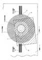
次に、本発明の実施の形態について図を参照しながら説明する。本発明の静電アクチュエータにおける構成の説明図を図1に示す。図1において、1は駆動シート、2は移動シート、11は向心性電極、12は回転性電極、13は向心性電極リード線、14は回転性電極リード線である。
駆動シート1は、その表面に対向して配置された移動シート2との間に静電力を発生することにより移動シート2の駆動を行うシートである。駆動シート1は向心性電極11と回転性電極12の少なくとも2つの電極領域を有する。向心性電極11の電極領域に移動シート2が存在するときに、向心性電極11に所定の駆動電圧を印加すると移動シート2には所定の位置(中心)に向かう静電力が作用する。したがって、向心性電極11の電極領域のことを向心性駆動領域と呼ぶ。また、回転性電極12の電極領域に移動シート2が存在するときに、回転性電極12に所定の駆動電圧を印加すると移動シート2には回転する静電力が作用する。したがって、回転性電極12の電極領域のことを回転性駆動領域と呼ぶ。図1に示す一例においては、駆動シート1の一角近くに向心性電極11と回転性電極12が設けられている。向心性電極11は、図1において、円領域の外周近くにおける渦巻状パターンの部分である。また、回転性電極12は、図1において、円領域の中央近くにおける放射状パターンの部分である。Next, embodiments of the present invention will be described with reference to the drawings. An explanatory diagram of the configuration of the electrostatic actuator of the present invention is shown in FIG. In FIG. 1, 1 is a drive sheet, 2 is a moving sheet, 11 is a centripetal electrode, 12 is a rotary electrode, 13 is a centripetal electrode lead, and 14 is a rotary electrode lead.
The driving sheet 1 is a sheet that drives the moving sheet 2 by generating an electrostatic force between the driving sheet 1 and the moving sheet 2 disposed to face the surface. The drive sheet 1 has at least two electrode regions of an
図1においてAで示す領域の拡大図を図2に示す。向心性電極リード線13は、図2に一例を示すように、3本を一組とする帯線状パターンである。帯線状パターンが3本を一組とする理由は、3相交流の電圧を印加するためである。図2に示すように、帯線状パターンの一方の端部と、図1において円の外周近くにおける向心性電極11の渦巻状パターンの部分とが結合している。渦巻状パターンの部分111は、その向心性電極リード線13が結合した渦巻状パターンの部分であり、円領域の渦巻状パターンにおける最外周の部分である。渦巻状パターンの部分111は、図2に示すように、3本(3相交流におけるU相、V相、W相)の電極線を一組とする渦巻状パターンのである。すなわち、図1に示す向心性電極11は、3重の電極線を所定位置を渦巻の中心として平面渦巻状に形成した渦巻電極パターンである。向心性電極11における3重の電極線には、3相交流の電圧が印加される。渦巻状パターンの部分111は、渦巻の中心に対して一周すると、渦巻状パターンの部分112につながっている。このように、向心性電極11は円領域の最外周の部分から回転性電極12が形成された円領域の中央近くまで形成された渦巻状パターンである。 FIG. 2 shows an enlarged view of a region indicated by A in FIG. The centripetal
このような、渦巻状パターンにおいては、渦巻の中心に向かって所定の割合で曲率半径が小さく(曲率が大きく)なっている。しかし、そのような連続的な渦巻状パターンを正確に生成することは必ずしも容易ではない。そこで、連続的な渦巻状パターンの代わりに、同心円を用いて同等の作用効果を有する渦巻状パターンを生成する方法が、図2における点線内に示されている。点線内において、渦巻状パターンにおける最外周の部分111は同心円であり、同心円(渦巻)の中心をほぼ一周すると、渦巻状パターンの部分112につながっている。渦巻状パターンにおける最外周の部分111と渦巻状パターンの部分112とが干渉しないように、渦巻状パターンの部分112は干渉する直前の位置において中心方向へと方向転換する。さらに、渦巻状パターンの部分112は渦巻状パターンにおける最外周の部分111の直近の内側において円周方向へと方向転換する。そして、渦巻状パターンの部分112は半径を小さくした同心円のパターンを形成する。向心性電極11はこのような方向転換を繰り返しながら形成された渦巻状パターンであってもよい。 In such a spiral pattern, the radius of curvature is reduced (the curvature is increased) at a predetermined rate toward the center of the spiral. However, it is not always easy to accurately generate such a continuous spiral pattern. Therefore, a method of generating a spiral pattern having the same effect by using concentric circles instead of a continuous spiral pattern is shown within a dotted line in FIG. In the dotted line, the outermost
図1においてBで示す領域の拡大図を図3に示す。Bで示す領域は向心性電極11と回転性電極12との境界領域である。向心性電極11は所定位置を渦巻の中心とする渦巻電極パターンである。また、回転性電極12は、図3に示す一例においては、その所定位置を放射の中心とする放射電極パターンである。したがって、図3に示すように、帯線状の電極である向心性電極11の帯線の延びる方向(長手方向)と、帯線状の電極である回転性電極12の帯線の延びる方向(長手方向)とのなす角度は90度(ほぼ90度)である。
向心性電極11は、図1においてAで示す領域において最外周の渦巻状パターンの部分111の端部が形成され、前述したように、その部分に向心性電極リード線13が結合している。また、向心性電極11は、図1においてBで示す領域において最内周の渦巻状パターンの部分113の端部が形成され、図3に示すように、その端部は開放されている。
回転性電極12は、向心性電極11とは独立した電極であり、互いの電極の間には結合関係はない。回転性電極12は、3本の電極線を一組とする放射状パターンである。3本(3相交流におけるU相、V相、W相)の電極線を一組とし、その放射状パターンの一組を円周方向に配列し全周方向に放射する放射状パターンとした構成となっている(図4参照)。すなわち、図3においては平行線のようであるが、実際は3重の電極線を平面放射状に形成した放射電極パターンである。また、放射電極パターンは所定位置を放射の中心としており、その所定位置を中心として移動シートに対して回転する静電力を作用させる。FIG. 3 shows an enlarged view of a region indicated by B in FIG. A region indicated by B is a boundary region between the
In the
The
図1においてCで示す領域の拡大図を図4(C)に示す。図4(C)に示す回転性電極12は平行な電極線で示されているが、実際は図4(C)において右側が放射の中心に向かって狭まり、左側がその中心から放射状に広がっている。また、図4(C)に示すU相結合線(1)、U相結合線(2)、V相結合線(1)、V相結合線(2)、W相結合線の各々、および向心性電極11は直線で示されているが、実際は放射の中心を円の中心とする円を描いている。
回転性電極12は多数の放射状に配列した電極線を有するが、それらの電極線の各々は3本(3相交流におけるU相、V相、W相)の電極線のいずれかに統合結合される。その結合を行うのが結合線である。
U相結合線は、図4(C)に示す回転性電極12の左側において縦方向に延びるU相結合線(1)とU相結合線(2)として示す結合線である。U相結合線(1)とU相結合線(2)とは、図4(C)においては切り離されているように見えるが、実際はU相結合線は円を描いており、その円のほぼ一周する弧として連続した一本の結合線である。
V相結合線は、図4(C)に示す回転性電極12の左側と右側の2箇所において縦方向に延びるV相結合線(1)とV相結合線(2)として示す結合線である。V相結合線(1)は電極線が形成されている表面の側からV相電極線を結合するとともに、他の相の電極線に対しては絶縁層を介する等により電気的に結合しない構成の結合線である。また、V相結合線(2)は電極線が形成されている表面の反対側からスルーホール等を介してV相電極線を結合する構成の結合線である。
W相結合線は、図4(C)に示す回転性電極12の右側において縦方向に延びる結合線である。An enlarged view of a region indicated by C in FIG. 1 is shown in FIG. The rotating
The
The U-phase coupling line is a coupling line shown as a U-phase coupling line (1) and a U-phase coupling line (2) extending in the vertical direction on the left side of the
The V-phase coupling line is a coupling line shown as a V-phase coupling line (1) and a V-phase coupling line (2) extending in the vertical direction at two places on the left and right sides of the
The W-phase coupling line is a coupling line extending in the vertical direction on the right side of the
図1においてDで示す領域の拡大図を図4(b)に示す。回転性電極リード線14は、図4(b)に示すように、放射状パターンである向心性電極11の外側に配置されている。一方、前述した渦巻状パターンである向心性電極11のリード線は、図1に示す一例においては、回転性電極リード線14の反対側に配置されている。
回転性電極リード線14は、図4に一例を示すように、3本を一組とする帯線状パターンである。帯線状パターンが3本を一組とする理由は、3相交流の電圧を印加するためである。
回転性電極リード線14のU相は、図4(C)、(b)に示すように、電極線が形成されている表面の側からU相結合線(1)を結合するとともに、向心性電極11等の他の相の電極線に対しては絶縁層を介する等により電気的に結合しない構成のリード線である。
回転性電極リード線14のV相は、同様に、電極線が形成されている表面の側からV相結合線(1)を結合するとともに、向心性電極11等の他の相の電極線に対しては絶縁層を介する等により電気的に結合しない構成のリード線である。
回転性電極リード線14のW相は、同様に、電極線が形成されている表面の側からW相結合線を結合するとともに、向心性電極11等の他の相の電極線に対しては絶縁層を介する等により電気的に結合しない構成のリード線である。
なお、リード線と、その各々に結合する結合線と、電極線とは3系統に一体化した導電線であり、リード線、結合線、電極線という区別は無意味にも思えるが、ここではその役割において区別する。すなわち、電源部から電力を供給する導電線の部分がリード線であり、リード線と電極線とを結合し電力を伝送する導電線の部分が結合線であり、移動シート2と駆動シート1における静電力が作用する主要な導電線の部分が電極線である。
An enlarged view of a region indicated by D in FIG. 1 is shown in FIG. As shown in FIG. 4B, the rotary
As shown in FIG. 4, the rotary
As shown in FIGS. 4 (C) and 4 (b), the U phase of the rotary
Similarly, the V-phase of the rotary
Similarly, the W phase of the rotary
Note that the lead wire, the bond wire coupled to each of the lead wire, and the electrode wire are conductive wires integrated in three systems, and the distinction between the lead wire, the bond wire, and the electrode wire seems meaningless, but here Distinguish by their role. That is, the portion of the conductive wire that supplies power from the power supply unit is a lead wire, and the portion of the conductive wire that couples the lead wire and the electrode wire to transmit power is the coupled wire. The part of the main conductive wire on which the electrostatic force acts is an electrode wire.
以上、駆動シート1に形成された向心性電極、回転性電極、等について説明した。次に、それらの電極を備えた静電アクチュエータの構成の一例について説明する。
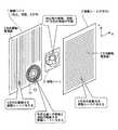
向心性電極と回転性電極を有する静電アクチュエータの構成の一例を図5に示す。図5において、1は駆動シート、2は移動シート、3は駆動シート、11は向心性電極、12は回転性電極である。
駆動シート1は、図1において向心性電極11の部分(向心性駆動領域)と回転性電極12の部分(回転性駆動領域)を有することを図示したが、図5に一例を示すように、それらとともにX方向駆動電極線の部分(X方向駆動領域)を有している。X方向駆動領域はY方向に延びる電極線によって構成される。
駆動シート3は、図5に一例を示すように、Y方向駆動電極線の部分(Y方向駆動領域)を有し、その部分が全領域となっている。Y方向駆動領域はX方向に延びる電極線によって構成される。The centripetal electrode, the rotary electrode, and the like formed on the drive sheet 1 have been described above. Next, an example of the configuration of an electrostatic actuator provided with these electrodes will be described.
An example of the configuration of an electrostatic actuator having a centripetal electrode and a rotary electrode is shown in FIG. In FIG. 5, 1 is a driving sheet, 2 is a moving sheet, 3 is a driving sheet, 11 is a centripetal electrode, and 12 is a rotating electrode.
The drive sheet 1 is illustrated in FIG. 1 as having a portion of the centripetal electrode 11 (centripetal drive region) and a portion of the rotatory electrode 12 (rotational drive region). As shown in FIG. Along with them, there is an X-direction drive electrode line portion (X-direction drive region). The X direction drive region is configured by electrode lines extending in the Y direction.
As shown in FIG. 5, the
駆動シート1のX方向駆動領域および駆動シート3のY方向駆動領域における電極構成について説明する。X方向駆動領域およびY方向駆動領域における電極線のパターンの一例を図6に示す。駆動シート1および駆動シート3において移動シート2との対向面に沿う方向に複数本が互いに平行となるように配列しているX方向駆動電極線およびY方向駆動電極線は、図6に示すパターンの一例においては中央部分に存在する。その中央部分を挟む左側部分と右側部分は、電極線の複数本をリード線に結合するための結合線である。
図6においては、U相結合線が左側部分に配置し、W相結合線が右側部分に配置している。また、U相結合線とW相結合線とは駆動シート1における表面に配置している。一方、V相結合線は駆動シート1における裏面に配置している。V相結合線は、図6に示すパターンの一例においては、左側部分と右側部分に分かれて配置している。V相電極線を表面に配置するためには、裏面に配置しているV相結合線からスルーホールにより表面に配置しているV相結合線に電気的な結合を行ない、その表面に配置しているV相結合線とV相電極線とを結合するパターンとする。The electrode configuration in the X-direction drive region of the drive sheet 1 and the Y-direction drive region of the
In FIG. 6, the U-phase coupling line is disposed on the left side, and the W-phase coupling line is disposed on the right side. Further, the U-phase coupling line and the W-phase coupling line are arranged on the surface of the drive seat 1. On the other hand, the V-phase coupling line is disposed on the back surface of the driving sheet 1. In the example of the pattern shown in FIG. 6, the V-phase coupling line is divided into a left part and a right part. In order to arrange the V-phase electrode line on the surface, the V-phase coupling line arranged on the back surface is electrically coupled to the V-phase coupling line arranged on the surface by a through hole, and arranged on the surface. The V-phase coupling line and the V-phase electrode line are connected to each other.
移動シート2は駆動シート1の表面にその一方の表面が対向するように配置される。駆動シート1のX方向駆動領域に対向する移動シート2の一方の表面はX方向駆動領域から駆動力を得て駆動シートに対して相対的に移動する。また、駆動シート1の向心性駆動領域に対向する移動シート2の表面は向心性駆動領域から駆動力を得て駆動シート1に対して相対的に移動する。また、駆動シート1の回転性駆動領域に対向する移動シート2の表面は回転性駆動領域から駆動力を得て駆動シート1に対して相対的に移動する。すなわち、移動シート2は、X方向駆動領域と向心性駆動領域と回転性駆動領域の組合せまたはいずれか1つの駆動力を受けて移動を行う。
移動シート2は、X方向駆動領域から駆動力を受けたときにはその駆動力の方向に従って左方向または右方向に移動する。また、向心性駆動領域から駆動力を受けたときには渦巻状パターンの中心方向に移動する。また、回転性駆動領域から駆動力を受けたときには放射状パターンの中心の回りに回転する。なお、向心性電極11に印加する3相交流電圧の位相によっては、中心方向に近づく移動ではなく、中心方向から離れる移動、すなわち遠心性の移動を行うこともできる。しかし、移動シート2の位置決めをするという目的においては中心方向に近づく移動だけが意味を有する。また、回転性電極12に印加する3相交流電圧の位相によって回転方向を制御することができる。この場合には、回転方向の制御は、移動シート2を所望の角度とする回転を最短時間で行うという意味を有する。
また、移動シート2は駆動シート3の表面にその他方の表面が対向するように配置される。駆動シート3のY方向駆動領域に対向する移動シート2の他方の表面はY方向駆動領域から駆動力を得て駆動シートに対して相対的に移動する。
移動シート2は、Y方向駆動領域から駆動力を受けたときにはその駆動力の方向に従って上方向または下方向に移動する。The moving sheet 2 is arranged so that one surface thereof faces the surface of the driving sheet 1. One surface of the moving sheet 2 facing the X direction driving area of the driving sheet 1 obtains a driving force from the X direction driving area and moves relative to the driving sheet. Further, the surface of the moving sheet 2 facing the centripetal driving area of the driving sheet 1 moves relative to the driving sheet 1 by obtaining driving force from the centripetal driving area. Further, the surface of the movable sheet 2 facing the rotational driving area of the driving sheet 1 obtains a driving force from the rotational driving area and moves relative to the driving sheet 1. That is, the movable sheet 2 moves by receiving a combination of the X-direction drive region, the centripetal drive region, and the rotational drive region or any one drive force.
When receiving the driving force from the X direction driving region, the moving sheet 2 moves to the left or right according to the direction of the driving force. In addition, when a driving force is received from the centripetal driving region, it moves toward the center of the spiral pattern. In addition, when a driving force is received from the rotational driving region, it rotates around the center of the radial pattern. Depending on the phase of the three-phase AC voltage applied to the
The movable sheet 2 is arranged so that the other surface faces the surface of the driving
When receiving the driving force from the Y-direction driving region, the moving sheet 2 moves upward or downward according to the direction of the driving force.
このような移動シート2は、駆動シート1、駆動シート3との間で静電力が働くことによって駆動シート1、駆動シート3に対して相対的な移動を行なうことができる。その移動は駆動シート1、駆動シート3に設けられた電極線に電源部から電圧を印加することにより行なわれる。その電圧の印加形態は制御部が電源部を制御することによって変化させることができる。そして、その電力の供給形態によって移動シート2の向心性または遠心性の移動方向の別と移動速度と移動量、回転性の移動における回転方向と回転速度と回転角度、XY方向の移動における移動方向と移動速度と移動量を変化させることができる。
特に、渦巻パターンの中心である所定の位置を中心として駆動シート1を回転させるときには、向心性の移動を行う3相交流電圧を向心性電極11に印加し続けた状態で、回転性の移動を行う3相交流電圧を回転性電極12に印加すればよい。これにより、移動シート2は回転中心のずれが自動補正されて、回転軸を有するかのように回転中心の安定した回転を行うことが可能となる。移動シート2の位置を検出してフィードバック制御を行う等の複雑な機構を必要としない。Such a moving sheet 2 can move relative to the driving sheet 1 and the driving
In particular, when the drive seat 1 is rotated around a predetermined position that is the center of the spiral pattern, the rotational movement is performed in a state in which a three-phase AC voltage that performs centripetal movement is continuously applied to the
移動シート2はその面が駆動シート1の面に対向して移動可能に配置され、その対向面に駆動シート1の電極電位に応じた電荷が誘起される。そして、その誘起された電荷と駆動シート1の電極電位との間に静電力が発生し、その発生した静電力によって駆動シート1に対して相対的な移動を行う。すなわち、移動シート2には電極電位に応じた電荷が誘起される必要性がある。したがって、移動シート2は一般的には絶縁材料(誘電体)であり、たとえば、ポリエステルフィルム、ポロプロピレンフィルム、ポリスチレンフィルム、ポリ塩化ビニール、ポリ塩化ビニリデンフィルム、ポリエチレンフィルム、ポリアミドフィルム、ポリイミドフィルム、等のプラスチックフィルムを使用することができる。また、そのような絶縁材料を駆動シート2との対向面にラミネートした(貼り合せた)紙、等の複合材料を使用することができる。移動シート2の表面は、表面抵抗率が約1012〜1015Ω□程度が好適である。この場合微弱な電気が流れるため、駆動シート2の電極線によって移動シート2に誘起された電荷は、電極線における電圧の瞬間的な変化に対して遅れて追従することになる。このような表面物性は材料表面の処理に大きく影響されることがあるため、使用することができる材料は上記に限定されず、コーティング処理で表面低効率を最適化してもよい。The movable sheet 2 is disposed so that the surface thereof is movable so as to face the surface of the drive sheet 1, and an electric charge corresponding to the electrode potential of the drive sheet 1 is induced on the opposite surface. Then, an electrostatic force is generated between the induced charge and the electrode potential of the driving sheet 1, and the relative movement with respect to the driving sheet 1 is performed by the generated electrostatic force. That is, it is necessary to induce a charge corresponding to the electrode potential in the moving sheet 2. Accordingly, the moving sheet 2 is generally an insulating material (dielectric), such as polyester film, polypropylene film, polystyrene film, polyvinyl chloride, polyvinylidene chloride film, polyethylene film, polyamide film, polyimide film, and the like. The plastic film can be used. In addition, a composite material such as paper obtained by laminating (bonding) such an insulating material to the surface facing the driving sheet 2 can be used. The surface of the movable sheet 2 preferably has a surface resistivity of about 1012 to 1015 Ω □. In this case, since weak electricity flows, the charge induced in the moving sheet 2 by the electrode line of the driving sheet 2 follows with a delay with respect to the instantaneous change of the voltage in the electrode line. Since such surface physical properties may be greatly influenced by the treatment of the material surface, the materials that can be used are not limited to the above, and the surface low efficiency may be optimized by a coating treatment.
本発明の静電アクチュエータの駆動シート1と駆動シート3は、たとえば、基材、電極(電極線、結合線、端子、等)、絶縁体、ハードコート層、潤滑層を順番に積層した構成とすることができる。次に、それらの構成の1つ1つについて説明する。
基材はその表面に形成した電極の電極形状を保持するための基材となるフィルムである。固定子基材としては、電気的な絶縁性を有し、かつハンダ付における耐熱性を有するプラスチックフィルム、たとえばPI(PolyImide)フィルム、PET(PolyEthyleneTerephthalate)フィルム、PAI(PolyAmideImide)フィルム、等、あるいはプラスチックフィルムではない他の材料として、ガラス基板、ガラスエポキシ基板、紙フェノール基板、フッ素樹脂基板、コンポジット基板、等を使用することができる。The drive sheet 1 and the
A base material is a film used as a base material for maintaining the electrode shape of the electrode formed on the surface. As a stator base material, a plastic film having electrical insulation and heat resistance when soldered, for example, a PI (PolyImide) film, a PET (PolyEthyleneTerephthalate) film, a PAI (PolyAmideImide) film, or a plastic As another material that is not a film, a glass substrate, a glass epoxy substrate, a paper phenol substrate, a fluororesin substrate, a composite substrate, or the like can be used.
電極はプリント回路を形成する周知の方法によって形成することができる。プリント回路の材料として銅箔とフィルムまたは基板を貼り合わせた銅貼フィルムが使用される。電極と固定子基材はその銅貼フィルムにおける銅箔の部分とフィルムの部分である。銅貼フィルムの銅箔面にエッチングレジストのパターンを形成してエッチングすることにより銅箔をパターン化することができる。帯線状の電極は、このパターン化した銅箔の部分として固定子基材の表面に形成される。
また、バックライトを透過させる等のために、電極として透明電極を必要とするときには、透明電極を形成する周知の方法によって電極を形成することができる。たとえば、ITO(酸化インジウム・スズ)を使用しスパッタリング、蒸着、等により基材に成膜しエッチングによりパターン化する、またはITOペーストをインキとし基材にスクリーン印刷して焼成する、等により透明電極を得ることができる。The electrode can be formed by a well-known method of forming a printed circuit. A copper-laminated film obtained by laminating a copper foil and a film or a substrate is used as a printed circuit material. An electrode and a stator base material are a copper foil part and a film part in the copper-coated film. The copper foil can be patterned by forming and etching an etching resist pattern on the copper foil surface of the copper-clad film. A strip-shaped electrode is formed on the surface of the stator base as a part of the patterned copper foil.
Moreover, when a transparent electrode is required as an electrode for transmitting a backlight or the like, the electrode can be formed by a known method for forming a transparent electrode. For example, using ITO (indium tin oxide) to form a film on a substrate by sputtering, vapor deposition, etc., and patterning by etching, or screen printing on an ITO paste as an ink and baking, etc. Can be obtained.
絶縁体は電極の露出している側の表面を被覆する絶縁体である。電極の固定子基材に貼り付いている側の表面は、当然ながら、固定子基材よって被覆されており電気的な絶縁性が確保されている。絶縁体はその表面に対して反対側となる固定子基材と電極の表面に密着して形成される。絶縁体は電気的な絶縁性を得るためだけではなく、駆動シート1と直角方向駆動シート3の全体の剛性を高くして変形を小さくし、移動子基材に対面する固定子基材の表面の平坦性を確保する働きを有している。
ハードコート層は固定子基材と移動子基材との摩擦による磨耗から、保護するためのハードコート層である。ハードコート層は基材と移動シート2とが対向する側の基材の表面に形成する。このハードコート層は、基材の厚さを極めて薄くしたときには(たとえば、20μm以下)、静電アクチュエータの耐久性において特に顕著な効果を示す構成要件となる。ハードコート層としては、周知のハードコート層を適用することができる。たとえば、フィルムに熱硬化性樹脂、紫外線硬化性樹脂、等を塗布して硬化させ形成したハードコート層を適用することができる。
潤滑層は固定子と移動子との間で発生する摩擦力を軽減するために固定子と移動子とが対面する(接触する)面の間に設けた潤滑層である。潤滑層を設けることにより駆動の効率性、安定性、等を向上させることができる。潤滑層としては流動体を使用することができる。たとえば、シリコーンオイル、フッ素系液体(たとえば、フロリナート(商標))、等の不活性かつ電気絶縁性を有する液体を使用すると好適である。また、滑り抵抗ではなく、潤滑層と同様の作用効果を有する直径10〜20μm程度のビーズを使用し転がり抵抗としてもよい。The insulator is an insulator that covers the exposed surface of the electrode. Naturally, the surface of the electrode attached to the stator base material is covered with the stator base material to ensure electrical insulation. The insulator is formed in close contact with the stator base and the surface of the electrode which are opposite to the surface. The insulator is not only for obtaining electrical insulation, but also increases the overall rigidity of the driving sheet 1 and the right-
The hard coat layer is a hard coat layer for protecting against abrasion due to friction between the stator base and the movable base. The hard coat layer is formed on the surface of the substrate on the side where the substrate and the moving sheet 2 face each other. When the thickness of the base material is extremely reduced (for example, 20 μm or less), this hard coat layer is a constituent requirement that exhibits a particularly remarkable effect on the durability of the electrostatic actuator. As the hard coat layer, a known hard coat layer can be applied. For example, a hard coat layer formed by applying and curing a thermosetting resin, an ultraviolet curable resin, or the like on the film can be applied.
The lubrication layer is a lubrication layer provided between the surfaces where the stator and the mover face (contact) to reduce the frictional force generated between the mover and the mover. By providing the lubricating layer, driving efficiency, stability, and the like can be improved. A fluid can be used as the lubricating layer. For example, it is preferable to use an inert and electrically insulating liquid such as silicone oil or fluorine-based liquid (for example, Florinart (trademark)). Further, instead of slip resistance, beads having a diameter of about 10 to 20 μm having the same effect as the lubricating layer may be used as rolling resistance.
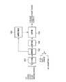
次に、本発明の静電アクチュエータにおける電源部について説明する。本発明の静電アクチュエータにおける電源部の構成の一例を図7に示す。図7において、101は入力器、102は制御器、103は高電圧電源、104は復号器、105は切替器であり、これらによって電源部が構成される。
入力器101は、制御の態様を指令する信号を入力し、制御器102に対してその信号を出力する部分である。すなわち、インタフェース、バッファ等の役割を有する部分である。その信号にはUP、DOWN、START、STOP、SPEEDが存在する。UPは移動シート2を上昇移行させる指令信号であり、DOWNは移動シート2を下降移行させる指令信号である。また、STARTは高電圧電源の電力供給を開始する指令信号であり、STOPは高電圧電源の電力供給を停止する指令信号である。また、SPEEDは3相交流における周波数を決定する指令信号である。Next, the power supply unit in the electrostatic actuator of the present invention will be described. An example of the configuration of the power supply unit in the electrostatic actuator of the present invention is shown in FIG. In FIG. 7, 101 is an input device, 102 is a controller, 103 is a high voltage power supply, 104 is a decoder, and 105 is a switch, and these constitute a power supply unit.
The
制御器102は入力器101から入力した指令信号に基づいて高圧電源103と復号器104を操作する操作信号を出力する制御器である。
高電圧電源103はグランドに対してプラス高電圧とマイナスの高電圧を出力する電源である。高電圧電源103は制御器102が出力する操作信号に基づいてプラス高電圧とマイナスの高電圧における出力電圧を変化することができる。出力電圧の範囲は、たとえば、200〜2000ボルト(V)である。
復号器104は、制御器102が出力する操作信号を切替器105を動作させる切替信号に複合化する。
切替器105は、復号器104が複合化する切替信号によって、高圧電源103の出力を切替える。その切替によって得られる出力は、たとえば、(1)3相正向進行波、(2)3相逆向進行波、(3)3つの出力をすべてプラス高電圧、(4)3つの出力をすべてマイナス高電圧、(5)3つの出力をすべてグランド(0電圧)のいずれかである。The
The high
The
The
上述の図7に示す電源部は、向心性駆動領域用の電源部、向心性駆動領域用の電源部、X方向駆動領域用の電源部、Y方向駆動領域用の電源部の4つが存在する。それら電源部の各々は、向心性電極リード線13、回転性電極リード線14、X方向駆動電極リード線(図示せず)、Y方向駆動電極リード線(図示せず)の各々に電力を供給する。
それら電源部の各々の入力器101が、各々の制御の態様を指令する信号を入力することによって、それら電源部の各々の切替器105から、各々の制御の態様に対応した電圧波形の電力が供給される。
以上から明らかなように、駆動シート1の向心性駆動領域、回転性駆動領域、X方向駆動領域、駆動シート3のY方向駆動領域は、各々が独立した制御の態様を受けることができる。したがって、移動シート2は向心性の移動、回転、X方向の移動、Y方向の移動、回転、およびそれらを組み合わせた任意の移動を行うことができる。The power supply unit shown in FIG. 7 includes four power supply units for the centripetal drive region, a power supply unit for the centripetal drive region, a power supply unit for the X direction drive region, and a power supply unit for the Y direction drive region. . Each of these power supplies supplies power to the centripetal
When each
As is clear from the above, the centripetal drive region, the rotational drive region, the X-direction drive region, and the Y-direction drive region of the
1 駆動シート
2 移動シート
11 向心性電極
12 回転性電極
13 向心性電極リード線
14 回転性電極リード線
101 入力器
102 制御器
103 高電圧電源
104 復号器
105 切替器DESCRIPTION OF SYMBOLS 1 Driving sheet 2 Moving
Claims (3)
Translated fromJapanese移動シートに対して回転する静電力を作用させるための回転性電極とを有し、
前記向心性電極は電極線を前記所定位置を渦巻の中心として平面渦巻状に形成した渦巻電極パターンであり、
前記渦巻電極パターンは前記渦巻の中心を一周する前に前記渦巻の中心方向へ方向転換し、さらに、前記渦巻の中心を円の中心とする円周方向へ方向転換させ、最外周から前記渦巻の中心方向に向かい前記渦巻の中心を巻回させていることを特徴とする静電アクチュエータ。
A centripetal electrode for applying an electrostatic force toward a predetermined position with respect to the moving sheet;
A rotating electrode for acting an electrostatic force rotating on the moving sheet;
The centripetal electrode is a spiral electrode pattern in which the electrode wire is formed in a planar spiral shape with the predetermined position being the center of the spiral,
The spiral electrode pattern changes direction to the center of the spiral before making a round of the center of the spiral, and further changes direction to the circumferential direction with the center of the spiral as the center of the circle. An electrostatic actuator characterized in thatthe center of the spiral is wound toward the center .
Priority Applications (1)
| Application Number | Priority Date | Filing Date | Title |
|---|---|---|---|
| JP2008244398AJP5277834B2 (en) | 2008-09-24 | 2008-09-24 | Electrostatic actuator |
Applications Claiming Priority (1)
| Application Number | Priority Date | Filing Date | Title |
|---|---|---|---|
| JP2008244398AJP5277834B2 (en) | 2008-09-24 | 2008-09-24 | Electrostatic actuator |
Publications (2)
| Publication Number | Publication Date |
|---|---|
| JP2010081680A JP2010081680A (en) | 2010-04-08 |
| JP5277834B2true JP5277834B2 (en) | 2013-08-28 |
Family
ID=42211479
Family Applications (1)
| Application Number | Title | Priority Date | Filing Date |
|---|---|---|---|
| JP2008244398AExpired - Fee RelatedJP5277834B2 (en) | 2008-09-24 | 2008-09-24 | Electrostatic actuator |
Country Status (1)
| Country | Link |
|---|---|
| JP (1) | JP5277834B2 (en) |
Family Cites Families (3)
| Publication number | Priority date | Publication date | Assignee | Title |
|---|---|---|---|---|
| DE69122022T2 (en)* | 1990-04-16 | 1997-02-06 | Fujitsu Ltd | ELECTROSTATIC ACTUATOR |
| JP2005116686A (en)* | 2003-10-06 | 2005-04-28 | Taiheiyo Cement Corp | Bipolar electrostatic chuck |
| JP2008042140A (en)* | 2006-08-10 | 2008-02-21 | Tokyo Electron Ltd | Electrostatic chuck device |
- 2008
- 2008-09-24JPJP2008244398Apatent/JP5277834B2/ennot_activeExpired - Fee Related
Also Published As
| Publication number | Publication date |
|---|---|
| JP2010081680A (en) | 2010-04-08 |
Similar Documents
| Publication | Publication Date | Title |
|---|---|---|
| CN105871089B (en) | A kind of printed circuit board stator | |
| WO2014169673A1 (en) | Rotary electrostatic power generation apparatus | |
| JP2013179262A (en) | Magnetic component | |
| JPWO2018193618A1 (en) | Coil body, stator, rotating machine, and method of manufacturing coil body | |
| JP5481567B2 (en) | Ion wind generator and ion wind generator | |
| JP5277834B2 (en) | Electrostatic actuator | |
| JP2016046837A (en) | Electrostatic motor and control device | |
| JP5309752B2 (en) | Electrostatic actuator | |
| JP2009284574A (en) | Two-phase driven static actuator | |
| JP5309753B2 (en) | controller | |
| CN205509674U (en) | Printed circuit board stator | |
| CN212660125U (en) | Rotary motor | |
| JP2010148207A (en) | Electrostatic actuator and manufacturing method therefor | |
| JP2009225563A (en) | Electrostatic actuator | |
| CN103956880B (en) | A kind of moving-iron type linear motor multi-disc type coil switching device and method | |
| CN113541437A (en) | Electrostatic stepping motor | |
| JP2009284573A (en) | Electrostatic actuator | |
| JP2009089476A (en) | Electrostatic operation device | |
| JP3470832B2 (en) | Multilayer electrode wiring board in electrostatic actuator and method of manufacturing the same | |
| JP5176524B2 (en) | Printed matter | |
| JP5556359B2 (en) | 4-wire electrostatic actuator and stator | |
| JP3470831B2 (en) | Multilayer electrode wiring board in electrostatic actuator and method of manufacturing the same | |
| CN113561159B (en) | Electrostatic driving device and electrostatic film robot | |
| JP2011205786A (en) | Four-wire electrostatic actuator | |
| JP5622082B2 (en) | Electrostatic actuator |
Legal Events
| Date | Code | Title | Description |
|---|---|---|---|
| A621 | Written request for application examination | Free format text:JAPANESE INTERMEDIATE CODE: A621 Effective date:20110623 | |
| A977 | Report on retrieval | Free format text:JAPANESE INTERMEDIATE CODE: A971007 Effective date:20121017 | |
| A131 | Notification of reasons for refusal | Free format text:JAPANESE INTERMEDIATE CODE: A131 Effective date:20121030 | |
| A521 | Request for written amendment filed | Free format text:JAPANESE INTERMEDIATE CODE: A523 Effective date:20121227 | |
| TRDD | Decision of grant or rejection written | ||
| A01 | Written decision to grant a patent or to grant a registration (utility model) | Free format text:JAPANESE INTERMEDIATE CODE: A01 Effective date:20130423 | |
| A61 | First payment of annual fees (during grant procedure) | Free format text:JAPANESE INTERMEDIATE CODE: A61 Effective date:20130506 | |
| R150 | Certificate of patent or registration of utility model | Ref document number:5277834 Country of ref document:JP Free format text:JAPANESE INTERMEDIATE CODE: R150 Free format text:JAPANESE INTERMEDIATE CODE: R150 | |
| S111 | Request for change of ownership or part of ownership | Free format text:JAPANESE INTERMEDIATE CODE: R313113 | |
| R350 | Written notification of registration of transfer | Free format text:JAPANESE INTERMEDIATE CODE: R350 | |
| R250 | Receipt of annual fees | Free format text:JAPANESE INTERMEDIATE CODE: R250 | |
| LAPS | Cancellation because of no payment of annual fees |