JP5277169B2 - Wireless via PON - Google Patents
Wireless via PONDownload PDFInfo
- Publication number
- JP5277169B2 JP5277169B2JP2009529427AJP2009529427AJP5277169B2JP 5277169 B2JP5277169 B2JP 5277169B2JP 2009529427 AJP2009529427 AJP 2009529427AJP 2009529427 AJP2009529427 AJP 2009529427AJP 5277169 B2JP5277169 B2JP 5277169B2
- Authority
- JP
- Japan
- Prior art keywords
- radio
- signal
- optical
- pon
- signals
- Prior art date
- Legal status (The legal status is an assumption and is not a legal conclusion. Google has not performed a legal analysis and makes no representation as to the accuracy of the status listed.)
- Expired - Fee Related
Links
- 230000003287optical effectEffects0.000claimsdescription53
- 238000006243chemical reactionMethods0.000claimsdescription9
- 239000000835fiberSubstances0.000claimsdescription8
- QSIOZNXDXNWPNX-AKEJEFCPSA-N(1r,2s,3r,5r)-3-(6-aminopurin-9-yl)-2-fluoro-5-(hydroxymethyl)-4-methylidenecyclopentan-1-olChemical compoundC1=NC=2C(N)=NC=NC=2N1[C@H]1[C@H](F)[C@H](O)[C@@H](CO)C1=CQSIOZNXDXNWPNX-AKEJEFCPSA-N0.000claims5
- 230000005540biological transmissionEffects0.000description11
- 238000000034methodMethods0.000description8
- 238000011144upstream manufacturingMethods0.000description8
- 238000005516engineering processMethods0.000description7
- 238000004891communicationMethods0.000description4
- 238000001228spectrumMethods0.000description4
- 230000001413cellular effectEffects0.000description3
- 239000013307optical fiberSubstances0.000description3
- 238000010168coupling processMethods0.000description2
- 238000010586diagramMethods0.000description2
- RYGMFSIKBFXOCR-UHFFFAOYSA-NCopperChemical compound[Cu]RYGMFSIKBFXOCR-UHFFFAOYSA-N0.000description1
- 230000002238attenuated effectEffects0.000description1
- 230000002457bidirectional effectEffects0.000description1
- 238000012986modificationMethods0.000description1
- 230000004048modificationEffects0.000description1
- 238000012545processingMethods0.000description1
- 230000000644propagated effectEffects0.000description1
- 238000000638solvent extractionMethods0.000description1
- 238000012546transferMethods0.000description1
Images


Classifications
- H—ELECTRICITY
- H04—ELECTRIC COMMUNICATION TECHNIQUE
- H04B—TRANSMISSION
- H04B10/00—Transmission systems employing electromagnetic waves other than radio-waves, e.g. infrared, visible or ultraviolet light, or employing corpuscular radiation, e.g. quantum communication
- H04B10/25—Arrangements specific to fibre transmission
- H04B10/2581—Multimode transmission
- H—ELECTRICITY
- H04—ELECTRIC COMMUNICATION TECHNIQUE
- H04W—WIRELESS COMMUNICATION NETWORKS
- H04W16/00—Network planning, e.g. coverage or traffic planning tools; Network deployment, e.g. resource partitioning or cells structures
- H04W16/24—Cell structures
- H04W16/26—Cell enhancers or enhancement, e.g. for tunnels, building shadow
- H—ELECTRICITY
- H04—ELECTRIC COMMUNICATION TECHNIQUE
- H04B—TRANSMISSION
- H04B10/00—Transmission systems employing electromagnetic waves other than radio-waves, e.g. infrared, visible or ultraviolet light, or employing corpuscular radiation, e.g. quantum communication
- H—ELECTRICITY
- H04—ELECTRIC COMMUNICATION TECHNIQUE
- H04B—TRANSMISSION
- H04B10/00—Transmission systems employing electromagnetic waves other than radio-waves, e.g. infrared, visible or ultraviolet light, or employing corpuscular radiation, e.g. quantum communication
- H04B10/25—Arrangements specific to fibre transmission
- H04B10/2575—Radio-over-fibre, e.g. radio frequency signal modulated onto an optical carrier
- H04B10/25752—Optical arrangements for wireless networks
- H04B10/25753—Distribution optical network, e.g. between a base station and a plurality of remote units
- H04B10/25754—Star network topology
- H—ELECTRICITY
- H04—ELECTRIC COMMUNICATION TECHNIQUE
- H04B—TRANSMISSION
- H04B10/00—Transmission systems employing electromagnetic waves other than radio-waves, e.g. infrared, visible or ultraviolet light, or employing corpuscular radiation, e.g. quantum communication
- H04B10/25—Arrangements specific to fibre transmission
- H04B10/2575—Radio-over-fibre, e.g. radio frequency signal modulated onto an optical carrier
- H04B10/25751—Optical arrangements for CATV or video distribution
- H—ELECTRICITY
- H04—ELECTRIC COMMUNICATION TECHNIQUE
- H04B—TRANSMISSION
- H04B10/00—Transmission systems employing electromagnetic waves other than radio-waves, e.g. infrared, visible or ultraviolet light, or employing corpuscular radiation, e.g. quantum communication
- H04B10/25—Arrangements specific to fibre transmission
- H04B10/2575—Radio-over-fibre, e.g. radio frequency signal modulated onto an optical carrier
- H04B10/25752—Optical arrangements for wireless networks
- H—ELECTRICITY
- H04—ELECTRIC COMMUNICATION TECHNIQUE
- H04B—TRANSMISSION
- H04B10/00—Transmission systems employing electromagnetic waves other than radio-waves, e.g. infrared, visible or ultraviolet light, or employing corpuscular radiation, e.g. quantum communication
- H04B10/27—Arrangements for networking
- H04B10/271—Combination of different networks, e.g. star and ring configuration in the same network or two ring networks interconnected
- H—ELECTRICITY
- H04—ELECTRIC COMMUNICATION TECHNIQUE
- H04W—WIRELESS COMMUNICATION NETWORKS
- H04W88/00—Devices specially adapted for wireless communication networks, e.g. terminals, base stations or access point devices
- H04W88/08—Access point devices
- H04W88/085—Access point devices with remote components
Landscapes
- Engineering & Computer Science (AREA)
- Computer Networks & Wireless Communication (AREA)
- Signal Processing (AREA)
- Physics & Mathematics (AREA)
- Electromagnetism (AREA)
- Optical Communication System (AREA)
- Mobile Radio Communication Systems (AREA)
- Small-Scale Networks (AREA)
Description
Translated fromJapanese本発明は、無線装置へ信号を送信し且つ無線装置から信号を受信するのに小型の加入者宅内機器(CPE)が使用される建物内にネイティブ(native)無線信号を送達するのに使用されるパッシブ光ネットワーク(PON)に関する。 The present invention is used to deliver native radio signals in buildings where small subscriber premises equipment (CPE) is used to send signals to and receive signals from the radio devices. The present invention relates to a passive optical network (PON).
セルラーネットワークのような無線ネットワークの大きな課題の1つは、室内カバレッジである。無線アンテナは典型的には建物の外側に配置されるが、多くの場合、ユーザは建物の内側に位置している。そのため、無線信号は建物の壁を通過しなければならない。信号は壁を通過する間に減衰し、通信品質を低下させる。 One of the major challenges of wireless networks such as cellular networks is indoor coverage. The wireless antenna is typically located outside the building, but in many cases the user is located inside the building. Therefore, the radio signal must pass through the building walls. The signal is attenuated while passing through the wall, thereby reducing the communication quality.
この室内カバレッジに関する課題はよく知られており、この課題に対処する方法がいくつか存在する。主に、リピータ及び室内分散アンテナシステム(DAS)である。いずれの方法も典型的には、オフィスビル、公共建築物、ショッピングセンター、及びキャンパスのような人口密度の高い場所に使用されている。 This issue of indoor coverage is well known and there are several ways to address this issue. It is mainly a repeater and indoor distributed antenna system (DAS). Both methods are typically used in densely populated places such as office buildings, public buildings, shopping centers, and campuses.
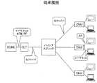
ここで、PONアーキテクチャの簡潔な概要を提供する。PONは、光ファイバを基にしたアクセスネットワークである。このネットワークは、ポイントツーマルチポイントネットワークとして構築され、光加入者線端局装置(OLT)として知られる単一の光インタフェースが、中央局(CO)又はヘッドエンド(HE)に配置され、複数のユーザ(典型的には16〜64のユーザ数)にサービス提供する。OLTは、光ファイバ(通常フィーダと呼ばれる)を介して、複数の光ファイバ(通常、配線又はドロップと呼ばれる)に光信号を分割するパッシブスプリッタに接続される。パッシブスプリッタは、COに配置することもできる(集中型スプリット:centralized split)し、フィールド内のパッシブキャビネットに配置することもできる(分散型スプリット:distributed split)。配線(又はドロップ)は、光信号を電気信号に変換する光加入者線終端装置(ONU)で終端する。ONUは、加入者宅に配置することもできるし(FTTH−ファイバ・ツー・ザ・ホームとしても知られている)、建物のインフラストラクチャ(たとえば、CAT 5)を使用してエンドユーザに電気信号を転送する加入者の建物に配置することもでき(FTTBとしても知られている)、また銅線(たとえば、DSL)を使用してエンドユーザに電気信号を転送するカーブ(the curb)に配置することもできる(FTTCとしても知られている)。PONには、APON、BPON、EPON、GPON、及びGePONのようないくつかの種類が存在する。すべての種類は、パッシブ分割の同じ基本アーキテクチャを共有し、データレート及びプロトコルによって互いに異なる。図1は、1つの典型的なPONを示す。 Here, a brief overview of the PON architecture is provided. PON is an access network based on optical fibers. This network is constructed as a point-to-multipoint network, where a single optical interface, known as an optical subscriber line terminal equipment (OLT), is located at the central office (CO) or headend (HE), Serving users (typically 16-64 users). The OLT is connected via an optical fiber (usually called a feeder) to a passive splitter that splits the optical signal into a plurality of optical fibers (usually called wires or drops). The passive splitter can be located in the CO (centralized split) or in a passive cabinet in the field (distributed split). The wiring (or drop) is terminated by an optical subscriber line termination unit (ONU) that converts an optical signal into an electrical signal. The ONU can be located at the subscriber's home (also known as FTTH-Fiber to the Home) or use the building infrastructure (eg, CAT 5) to provide electrical signals to the end user. (Also known as FTTB) or in the curb that uses copper wire (eg, DSL) to transfer electrical signals to the end user (Also known as FTTC). There are several types of PONs such as APON, BPON, EPON, GPON, and GePON. All types share the same basic architecture of passive partitioning and differ from one another by data rate and protocol. FIG. 1 shows one typical PON.
携帯電話のような無線通信のための改善された室内カバレッジが必要とされているが、従来の解決法は、これに関してPONアーキテクチャを採用する可能性を有効に利用していない。 There is a need for improved indoor coverage for wireless communications such as mobile phones, but conventional solutions do not effectively take advantage of the possibility of adopting a PON architecture in this regard.
[発明の概要]
本発明は、商業ビル及び公共建築物はもちろん民家及びアパートのような住宅立地にも関する室内カバレッジの課題に対処する。無線装置へ信号を送信し且つ無線装置から信号を受信するのに小型の加入者宅内機器(CPE)が使用される建物内にネイティブ無線信号を送達するのにパッシブ光ネットワーク(PON)が使用される本発明によれば、携帯電話技術(すなわち、GSM900、GSM1800、PCS、UMTS、CDMA、iDEN等)、無線LAN技術(たとえば、WiFi)、WiMAX、及び他の OFDM/OFDMA技術.1のような多くの種類の無線技術がサポートされる。[Summary of Invention]
The present invention addresses the issue of indoor coverage not only for commercial buildings and public buildings, but also for residential locations such as private houses and apartments. Passive optical networks (PON) are used to deliver native wireless signals in buildings where small customer premises equipment (CPE) is used to send signals to and receive signals from wireless devices. In accordance with the present invention, mobile phone technology (ie GSM900, GSM1800, PCS, UMTS, CDMA, iDEN, etc.), wireless LAN technology (eg, WiFi), WiMAX, and other OFDM / OFDMA technologies. Many types of wireless technologies such as 1 are supported.
本発明の一態様によれば、無線信号を通信するためのシステムが提供され、当該システムは、中央局(CO)とネットワーク加入者との間のパッシブ光ネットワーク(PON)を備え、COは光加入者線端局装置(OLT)及び無線基地局を有する。RF/光変換器が、基地局無線周波数(RF)信号を、対応する光信号に変換し且つ対応する光信号から変換する。ネットワーク加入者のうちの1人又は複数人のロケーションにおいてPONを介して少なくとも1つの光加入者線終端装置(ONU)と通信するために、光結合器がOLTの信号とRF/光変換器の信号とを結合し、その結果、OLTの信号及び変換された無線基地局の信号は、PONを介して共に搬送される。 According to one aspect of the invention, a system for communicating wireless signals is provided, the system comprising a passive optical network (PON) between a central office (CO) and a network subscriber, where the CO is optical. It has a subscriber line terminal equipment (OLT) and a radio base station. An RF / optical converter converts a base station radio frequency (RF) signal into a corresponding optical signal and from the corresponding optical signal. In order to communicate with at least one optical subscriber line termination unit (ONU) via the PON at the location of one or more of the network subscribers, an optical coupler is used to transmit the OLT signal and the RF / optical converter. Combined so that the OLT signal and the converted radio base station signal are carried together via the PON.
ファイバマウント無線アンテナユニット(fiber mounted wireless antenna unit)(FMCA)は、光インタフェース及び無線アンテナを有し、無線RF信号と光信号との間の変換を実行することを含めて、無線アンテナの無線信号をONUと通信する。FMCAは、変換された無線基地局信号をPONから取得し、それらの無線基地局信号を変換し直して、無線アンテナを使用してFMCAによって伝送するために再変換されたRF信号を提供し、また、無線アンテナから無線RF信号を取得し、それらの無線RF信号を変換してCOにおける無線基地局へのPONを介した通信のために光信号を提供する。このように、当該システムは、加入者のロケーションでの無線カバレッジを提供する。 A fiber mounted wireless antenna unit (FMCA) has an optical interface and a wireless antenna, and includes a radio signal for the wireless antenna, including performing conversion between a wireless RF signal and an optical signal. Communicate with the ONU. FMCA obtains converted radio base station signals from the PON, reconverts those radio base station signals, and provides a reconverted RF signal for transmission by FMCA using a radio antenna; It also obtains wireless RF signals from the wireless antenna, converts those wireless RF signals, and provides optical signals for communication via PON to the wireless base station in the CO. In this way, the system provides radio coverage at the subscriber's location.
一実施の形態によれば、FMCA及びONUは一つに統合されている。 According to one embodiment, FMCA and ONU are integrated into one.
他の実施の形態は、PONを介して使用される周波数が、無線通信信号専用であるか、又は無線信号とPONを介して搬送される他の信号との間で共有されるかを伴う。 Other embodiments involve whether the frequency used via the PON is dedicated to the radio communication signal or shared between the radio signal and other signals carried via the PON.
本発明は、同封の図面を参照することによってより容易に理解されるであろう。図面では、本発明の中心原理を不明瞭にすることを避けるために多くの特殊性は省かれている。 The present invention will be more readily understood with reference to the accompanying drawings. In the drawings, many specificities have been omitted to avoid obscuring the central principles of the present invention.
本発明は、以下に述べる特定の明確な実施形態に関して原理的に説明される。本論考は読者に本発明の原理を教示するための役割を果たすが、本発明の一部として考えられ得る、任意の且つあらゆる可能な実施形態を説明することは実際的ではない。したがって、例示的な実施形態が本発明を教示するために提供され、添付の特許請求の範囲は、本発明の精神内に入る主題の範囲を画定するために提供される。 The invention will be described in principle with respect to certain specific embodiments described below. While this discussion serves to teach the reader the principles of the invention, it is not practical to describe any and all possible embodiments that can be considered as part of the invention. Accordingly, the exemplary embodiments are provided to teach the invention, and the appended claims are provided to define the scope of the subject matter that falls within the spirit of the invention.
ここで、PONの論考に戻ると、2種類の伝送、すなわちデジタル伝送及びRF伝送がPONを介して使用される。デジタル伝送は典型的には、IPパケットがATM(たとえば、APON、BPON、及びGPON)又はイーサネット(登録商標)(たとえば、EPON、GPON、GePON)のいずれかを介して搬送されるインターネットアクセスに使用される。デジタル伝送は典型的には、双方向伝送であり、ここで各方向は異なる波長によって搬送される。典型的な波長は、アップストリームに対して1310nmであり、ダウンストリームに対して1490nm(APON、BPON、及びGPON)又は1550nm(EPON、及びGePON)である。あまり一般的ではないが、別の選択肢は、各方向に対して異なるファイバを使用することである。 Now, returning to the PON discussion, two types of transmission are used via the PON: digital transmission and RF transmission. Digital transmission is typically used for Internet access where IP packets are carried over either ATM (eg, APON, BPON, and GPON) or Ethernet (eg, EPON, GPON, GePON) Is done. Digital transmission is typically bidirectional transmission, where each direction is carried by a different wavelength. Typical wavelengths are 1310 nm for the upstream and 1490 nm (APON, BPON and GPON) or 1550 nm (EPON and GePON) for the downstream. Although less common, another option is to use a different fiber for each direction.
RF伝送は通例、ダウンストリーム方向においてCATV伝送に使用される。CATV RF信号は、典型的には1550nmの波長で光信号に変換され、PONに沿ってONUに転送される。ONUは、光信号をRF信号に変換し直す。ONUのRF出力は、CATVセットトップボックスのRF入力に接続され、既存のCATVのヘッドエンド機器及びセットトップボックスを使用しながらPONを介したCATV信号の伝送を可能にする。 RF transmission is typically used for CATV transmission in the downstream direction. The CATV RF signal is typically converted to an optical signal at a wavelength of 1550 nm and transferred to the ONU along the PON. The ONU converts the optical signal back to an RF signal. The RF output of the ONU is connected to the RF input of the CATV set top box, allowing the transmission of CATV signals via the PON while using existing CATV headend equipment and set top boxes.
以下のセクションは、PONインフラストラクチャを使用して室内無線カバレッジを提供するシステムを説明する。そのようなシステムの主な用途がたとえ室内カバレッジであっても、当該システムは、PONが配備されており且つ既存の室外無線カバレッジが不十分であるロケーションにおける室外カバレッジにも同様に使用することもできる。 The following section describes a system that provides indoor radio coverage using a PON infrastructure. Even if the primary use of such a system is indoor coverage, the system can be used for outdoor coverage in locations where PON is deployed and existing outdoor radio coverage is insufficient. it can.
提案されている本発明によれば、ネイティブ無線信号は、COと各ネットワーク加入者との間でPONを介して転送される。無線基地局はCOに設置され、好ましくはOLTと同一の場所に配置される。基地局RF信号は、RF/光変換器を使用して光信号に変換される。光信号は、OLT光信号と結合され、PONに沿ってONUまで伝搬される。光インタフェース及び無線アンテナを備えているFMCA(Fiber Mounted Cellular Antenna)(ファイバマウントセルラアンテナ)と呼ばれる小型のCPEは、加入者宅に設置され、ONUと同じ場所に配置されるか、又はさらにはONUに統合されるのが好ましい。FMCAは、無線基地局のRF信号から生じた光信号を分離し、RF信号に変換し直す。これらのRF信号は、無線アンテナを使用してFMCAによって伝送され、FMCAの近傍において無線カバレッジを提供する。 According to the proposed invention, native radio signals are transferred between the CO and each network subscriber via the PON. The radio base station is installed in the CO, preferably in the same location as the OLT. The base station RF signal is converted to an optical signal using an RF / optical converter. The optical signal is combined with the OLT optical signal and propagates along the PON to the ONU. A small CPE called FMCA (Fiber Mounted Cellular Antenna) equipped with an optical interface and a wireless antenna is installed at the subscriber's home and is co-located with the ONU or even ONU It is preferable to be integrated. FMCA separates an optical signal generated from the radio base station RF signal and converts it back to an RF signal. These RF signals are transmitted by the FMCA using a radio antenna and provide radio coverage in the vicinity of the FMCA.
アップストリーム方向において、無線信号は、FMCAによって受信され、光信号に変換される。これらの信号は、ONUによって生成された光信号と結合され、PONを介してCOに転送される。アップストリーム方向において、PONパッシブスプリッタは、結合器として機能し、いくつかのFMCAによって生成された光信号を結合することに留意されたい。結合された光信号は、COにおいて受信され、COにおいて、FMCAから生じた光信号はRF信号に変換し直される。これらの信号は、無線基地局のRF入力に転送される。このように、基地局は、各FMCAのアンテナによって受信されるすべての信号を受信する。 In the upstream direction, the radio signal is received by the FMCA and converted into an optical signal. These signals are combined with the optical signal generated by the ONU and transferred to the CO via the PON. Note that in the upstream direction, the PON passive splitter acts as a combiner and combines optical signals generated by several FMCAs. The combined optical signal is received at the CO, where the optical signal generated from FMCA is converted back to an RF signal. These signals are transferred to the radio base station RF input. Thus, the base station receives all signals received by each FMCA antenna.
以下のセクションは、無線信号をPONの他の信号に結合するためのいくつかの方法を説明する。各方法は、アップストリーム方向又はダウンストリーム方向のいずれかで実施することができ、また各方向は異なる方法を使用して実施することができることに留意されたい。 The following sections describe several methods for combining a radio signal with other signals in the PON. Note that each method can be implemented in either the upstream or downstream direction, and each direction can be implemented using a different method.
専用波長、無線周波数(電波周波数)(air frequency)
図2は、無線サポートを有するPONを示す。Dedicated wavelength, radio frequency (air frequency)
FIG. 2 shows a PON with wireless support.
すでに説明したように、PON信号はいくつかの波長によって搬送される。典型的には、1490nm及び1550nmの波長がダウンストリームトラフィックに使用され、1310の波長がアップストリームトラフィックに使用される。提案されている本発明によれば、無線信号は、PONによって使用されていないさらなる波長によって搬送される。双方向に対して単一のファイバを使用してPONが実施される場合、2つの波長を次のように使用するべきである。すなわち、一方の波長は無線ダウンストリーム信号に使用されるべきであり、他方の波長は無線アップストリーム信号に使用されるべきである。ダウンストリーム波長はすべてのPON加入者のダウンストリームトラフィックを搬送し、アップストリーム波長はすべてのPON加入者からのアップストリームトラフィックを搬送する。各方向に1つずつ2つのファイバを使用して実施されるPONの場合、同じ波長が双方向に対して使用され得る。無線アプリケーションに使用される波長は、PONパッシブスプリッタによってサポートされる範囲内にあるべきであることに留意されたい。たとえば、1490nmの波長を使用しないEPONにおいて、この波長を双方向のうちの一方向の無線トラフィックを搬送するのに使用することができる。 As already explained, the PON signal is carried by several wavelengths. Typically, 1490 nm and 1550 nm wavelengths are used for downstream traffic and 1310 wavelengths are used for upstream traffic. According to the proposed invention, radio signals are carried by additional wavelengths that are not used by the PON. If PON is implemented using a single fiber for both directions, the two wavelengths should be used as follows. That is, one wavelength should be used for the radio downstream signal and the other wavelength should be used for the radio upstream signal. The downstream wavelength carries downstream traffic for all PON subscribers, and the upstream wavelength carries upstream traffic from all PON subscribers. For a PON implemented using two fibers, one in each direction, the same wavelength can be used for both directions. Note that the wavelengths used for wireless applications should be within the range supported by the PON passive splitter. For example, in an EPON that does not use a wavelength of 1490 nm, this wavelength can be used to carry radio traffic in one of two directions.
RF信号は、一切の周波数変換も他の処理も伴わずに、無線(air)で使用される同じ周波数において、専用波長でそのままで光信号に変換される。異なる技術(たとえば、UMTS、GSM)及び異なる無線(たとえば、セルラ)オペレータは、異なる周波数を使用しているため、異なる無線ネットワーク(同じ技術又は異なる技術のいずれか、同じオペレータ又は異なるオペレータのいずれか)の信号は、一つに結合され、ネットワーク間で一切重なることなく同じPONを介して伝搬され得る。 The RF signal is converted into an optical signal as it is at a dedicated wavelength at the same frequency used in the air without any frequency conversion or other processing. Different technologies (eg UMTS, GSM) and different radio (eg cellular) operators use different frequencies, so different radio networks (either the same technology or different technologies, either the same operator or different operators) ) Signals can be combined together and propagated through the same PON without any overlap between networks.
専用波長、シフトされる周波数
ここで説明される結合方法は、上記で説明した結合方法と同様である。いずれの方法においても、RF信号は専用波長によって搬送されるが、この方法では、RF信号の周波数は、通例、より低い周波数にシフトされる(又は、変換される)。GSM帯域又はUMTS帯域のような全無線帯域の、RFから光への変換及びその逆の変換は、高価な広帯域RF/光変換器を必要とする。無線オペレータは帯域のわずかな部分(たとえば、10MHz)しか使用していないため、帯域のこの部分を、より低い周波数にシフトし、光信号に変換し、ネットワークの他方の終端においてRF周波数に変換し直して、元の周波数にシフトし直すことができる。このようにして、より狭い帯域及びより安価なコンポーネントを使用することができる。この方法はまた、各ネットワークの実際の帯域をPONの一方の終端において異なる周波数帯域にシフトすることによって複数の無線ネットワークをサポートし、その帯域をPONの他方の終端において元の無線周波数にシフトし直すこともできる。Dedicated wavelength, shifted frequency The coupling method described here is similar to the coupling method described above. In either method, the RF signal is carried by a dedicated wavelength, but in this method, the frequency of the RF signal is typically shifted (or converted) to a lower frequency. The conversion from RF to light and vice versa for all radio bands such as GSM band or UMTS band requires expensive broadband RF / optical converters. Since the radio operator uses only a small part of the band (eg 10 MHz), this part of the band is shifted to a lower frequency, converted to an optical signal, and converted to an RF frequency at the other end of the network. It can be corrected and shifted back to the original frequency. In this way, narrower bandwidths and less expensive components can be used. This method also supports multiple wireless networks by shifting the actual band of each network to a different frequency band at one end of the PON and shifting that band to the original radio frequency at the other end of the PON. You can fix it.
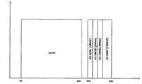
共有波長、無線周波数
図3は、CATVアプリケーションと、GSM900及びGSM1800の2つの帯域とによって共有されるダウンリンク波長のスペクトルを描写する。Shared Wavelength, Radio Frequency FIG. 3 depicts the spectrum of the downlink wavelength shared by the CATV application and the two bands of GSM900 and GSM1800.
場合によっては、既存のPONアプリケーション及び無線アプリケーションによって単一の波長が共有されることがある。無線RF周波数範囲が、既存のPONアプリケーションによって使用される周波数を下回るか又は上回る場合、2つの信号はRFから光に変換する前に結合され得る。これは、実際は、各アプリケーションが自身の周波数範囲を使用する周波数分割多重化(FDM)である。結合された信号は、光からRFに変換されるとともに、ネットワークの他方の終端において単一のRF/光変換器を使用してRFから光に変換される。 In some cases, a single wavelength may be shared by existing PON and wireless applications. If the wireless RF frequency range is below or above the frequency used by existing PON applications, the two signals can be combined before converting from RF to light. This is actually frequency division multiplexing (FDM) where each application uses its own frequency range. The combined signal is converted from light to RF and RF to light using a single RF / light converter at the other end of the network.
たとえば、或るBPONネットワーク又はGPONネットワークにおいて、1550nm波長は、50MHz〜860MHzの周波数範囲内のCATV信号を搬送するのに使用される。GSM900ネットワークは、ダウンリンク信号に対して900MHzを上回る周波数を利用するため、GSM900ダウンリンク信号は、ヘッドエンド/COにおいてRFから光に変換される前にCATV RF信号と結合することができる。ネットワークの遠端において、信号は、光からRFに変換した後にフィルタを使用して分離され得る。860MHzを下回る低い方の帯域はCATV受信機(たとえば、セットトップボックス)にルーティングされ、900MHzを上回る高い方の帯域は、無線での伝送のためにFMCAにルーティングされる。無線ネットワークによって使用される周波数範囲と既存のPONアプリケーションによって使用される周波数範囲との間で重なりが存在しない限り、この方法において同様に複数の無線ネットワークをサポートすることができることに留意されたい。たとえば、CATVに使用される波長を、860MHzを下回る周波数範囲を使用する無線ネットワークと共有することはできない。 For example, in some BPON or GPON networks, 1550 nm wavelengths are used to carry CATV signals in the frequency range of 50 MHz to 860 MHz. Since GSM900 networks utilize frequencies above 900 MHz for downlink signals, GSM900 downlink signals can be combined with CATV RF signals before being converted from RF to light at the headend / CO. At the far end of the network, signals can be separated using filters after conversion from light to RF. The lower band below 860 MHz is routed to the CATV receiver (eg, set top box) and the higher band above 900 MHz is routed to FMCA for wireless transmission. It should be noted that multiple wireless networks can be supported in this manner as long as there is no overlap between the frequency range used by the wireless network and the frequency range used by existing PON applications. For example, the wavelength used for CATV cannot be shared with a wireless network that uses a frequency range below 860 MHz.
共有波長、シフトされる周波数
上述したように、広帯域RF信号の光信号への変換及びその逆の変換は、高価な広帯域RF/光変換器を必要とする。「共有波長、無線周波数」において紹介された方法は、既存のPONアプリケーション及び無線ネットワークの結合範囲のRF/光変換を必要とする。そのセクションにおいて説明された例を考慮すると、CATVアプリケーションによって使用される周波数範囲は、50MHzに始まり、860MHzで終わる。この信号をUMTS信号に結合することによって、結果的に全帯域幅は2GHzを超える。RF/光変換器の帯域幅(及びコスト)を削減するために、UMTS信号を、無線周波数からPONアプリケーションによって使用されていない周波数にシフトすることができる。図4を参照されたい。周波数シフトは、無線帯域全体(たとえば、UMTS帯域全体)で、又は無線オペレータによって実際に使用される、帯域の一部(たとえば、UMTS帯域内で搬送波毎に5MHz)で行うことができる。複数のネットワークの場合、各ネットワークの信号を異なる未使用周波数範囲にシフトすることができる。以下の図は、CATVアプリケーションと、2つのGSMネットワーク及び2つのUMTSネットワークの4つの無線ネットワークとによって共有されるダウンリンク波長のスペクトルを描写する。これらのネットワークによって使用される全帯域幅は25MHzである。Shared wavelength, shifted frequency As mentioned above, the conversion of broadband RF signals to optical signals and vice versa requires expensive broadband RF / optical converters. The method introduced in “Shared Wavelength, Radio Frequency” requires RF / optical conversion of existing PON applications and the combined range of wireless networks. Considering the example described in that section, the frequency range used by CATV applications starts at 50 MHz and ends at 860 MHz. By combining this signal with the UMTS signal, the resulting total bandwidth exceeds 2 GHz. To reduce the bandwidth (and cost) of the RF / optical converter, the UMTS signal can be shifted from a radio frequency to a frequency not used by the PON application. Please refer to FIG. The frequency shift can be performed on the entire radio band (eg, the entire UMTS band) or on a portion of the band (eg, 5 MHz per carrier within the UMTS band) that is actually used by the radio operator. In the case of multiple networks, the signals of each network can be shifted to different unused frequency ranges. The following figure depicts the spectrum of downlink wavelengths shared by the CATV application and four wireless networks, two GSM networks and two UMTS networks. The total bandwidth used by these networks is 25 MHz.
当該技術分野に精通している者(one familiar with this field:当業者)は理解するように、多くの変形及び変更を本発明の範囲及び精神から逸脱することなく行うことができる。さまざまな代替形態を上記で提示した。そして他の代替形態を、関心のある読者は思い付くであろう。 As those skilled in the art will appreciate, many variations and modifications can be made without departing from the scope and spirit of the invention. Various alternatives are presented above. And interested readers will come up with other alternatives.
Claims (7)
Translated fromJapanese中央局(CO)とネットワーク加入者との間のパッシブ光ネットワーク(PON)であって、前記COは光加入者線端局装置(OLT)及び無線基地局を有する、パッシブ光ネットワーク(PON)、
無線基地局無線周波数(RF)信号を周波数シフトするとともに、前記無線基地局RF信号を、対応する光信号に且つ該光信号から変換するRF/光変換器、
前記ネットワーク加入者のうちの1人又は複数人のロケーションにおいて少なくとも1つの光加入者線終端装置(ONU)と前記PONを介して通信するために、前記OLTの信号と前記RF/光変換器の信号とを結合する光結合器であって、それによって、前記OLTの信号及び変換された無線基地局信号を前記PONを介して共に搬送する、光結合器、並びに
光インタフェース及び無線アンテナを有すると共に、無線RF信号と光信号との間の変換を実行することを含めて、前記無線アンテナの無線信号を前記ONUと通信するファイバマウント無線アンテナユニット(FMCA)、
を備え、
前記FMCAは、
前記変換された無線基地局信号を前記PONから取得し、該変換された無線基地局信号を変換し直して、前記無線アンテナを使用して該FMCAによって伝送するために、再変換されたRF信号を提供し、
また、前記無線アンテナから無線RF信号を取得し、該無線RF信号を変換して、前記COにおける前記無線基地局へ前記PONを介して通信するために、光信号を提供し、
それによって、前記ネットワーク加入者のうちの前記1人又は複数人の前記ロケーションでの無線カバレッジを提供する、無線信号を通信するためのシステム。A system for communicating radio signals,
A passive optical network (PON) between a central office (CO) and a network subscriber, wherein the CO comprises an optical subscriber line terminal equipment (OLT) and a radio base station, a passive optical network (PON),
An RF / optical converterthat frequency shifts a radio base station radio frequency (RF) signal and converts theradio base station RF signal to and from the corresponding optical signal;
In order to communicate with at least one optical subscriber line termination unit (ONU) at the location of one or more of the network subscribers via the PON, the signals of the OLT and the RF / optical converter An optical combiner for combining signals with an optical combiner for carrying together the OLT signal and the converted radio base station signal via the PON, and an optical interface and a radio antenna A fiber mount radio antenna unit (FMCA) for communicating radio signals of the radio antenna with the ONU, including performing conversion between radio RF signals and optical signals;
With
The FMCA is
Reconverted RF signal for obtaining the converted radio base station signal from the PON, reconverting the converted radio base station signal and transmitting by the FMCA using the radio antenna Provide
Also, obtaining a radio RF signal from the radio antenna, converting the radio RF signal, and providing an optical signal to communicate via the PON to the radio base station in the CO,
A system for communicating radio signals thereby providing radio coverage at the location of the one or more of the network subscribers.
Applications Claiming Priority (2)
| Application Number | Priority Date | Filing Date | Title |
|---|---|---|---|
| US82667906P | 2006-09-22 | 2006-09-22 | |
| PCT/US2007/079322WO2008036976A2 (en) | 2006-09-22 | 2007-09-24 | Wireless over pon |
Publications (2)
| Publication Number | Publication Date |
|---|---|
| JP2010541297A JP2010541297A (en) | 2010-12-24 |
| JP5277169B2true JP5277169B2 (en) | 2013-08-28 |
Family
ID=39201367
Family Applications (1)
| Application Number | Title | Priority Date | Filing Date |
|---|---|---|---|
| JP2009529427AExpired - Fee RelatedJP5277169B2 (en) | 2006-09-22 | 2007-09-24 | Wireless via PON |
Country Status (8)
| Country | Link |
|---|---|
| US (1) | US9554284B2 (en) |
| EP (1) | EP2067289B1 (en) |
| JP (1) | JP5277169B2 (en) |
| KR (1) | KR20090073192A (en) |
| CN (1) | CN101536382A (en) |
| CA (1) | CA2664227A1 (en) |
| IL (1) | IL197735A0 (en) |
| WO (1) | WO2008036976A2 (en) |
Families Citing this family (34)
| Publication number | Priority date | Publication date | Assignee | Title |
|---|---|---|---|---|
| US8380143B2 (en) | 2002-05-01 | 2013-02-19 | Dali Systems Co. Ltd | Power amplifier time-delay invariant predistortion methods and apparatus |
| US8811917B2 (en) | 2002-05-01 | 2014-08-19 | Dali Systems Co. Ltd. | Digital hybrid mode power amplifier system |
| US8623067B2 (en)* | 2004-05-25 | 2014-01-07 | Covidien Lp | Methods and apparatus for luminal stenting |
| CN102017553B (en) | 2006-12-26 | 2014-10-15 | 大力系统有限公司 | Method and system for baseband predistortion linearization in a multi-channel broadband communication system |
| KR101212337B1 (en)* | 2008-06-30 | 2012-12-13 | 주식회사 케이티 | Rf femto-cell system using ftth network |
| TWI416884B (en)* | 2008-09-04 | 2013-11-21 | Univ Nat Kaohsiung Applied Sci | Passive-optical-network transmission system capable of receiving wireless signals |
| CN102209921B (en) | 2008-10-09 | 2015-11-25 | 康宁光缆系统有限公司 | There is the fibre-optic terminus supported from the adapter panel of the input and output optical fiber of optical splitters |
| US8285227B2 (en)* | 2008-12-31 | 2012-10-09 | Elektrobit System Test Oy | Communication between transmitter and receiver |
| CN106130646B (en) | 2009-03-05 | 2019-04-30 | Adc电信公司 | Methods, systems and apparatus for integrating wireless technologies into fiber optic networks |
| CN101841748B (en)* | 2009-03-17 | 2013-06-12 | 中国移动通信集团公司 | Signal transmission system and relevant device |
| US8346091B2 (en)* | 2009-04-29 | 2013-01-01 | Andrew Llc | Distributed antenna system for wireless network systems |
| KR101142458B1 (en)* | 2009-06-09 | 2012-05-08 | 넷포드 주식회사 | Mobile communication base station network system |
| CN101959086A (en)* | 2009-07-15 | 2011-01-26 | 中兴通讯股份有限公司 | Time division multiplex and wavelength division multiplex coexisting passive optical network system and transmission method |
| KR101835254B1 (en) | 2010-08-17 | 2018-03-06 | 달리 시스템즈 씨오. 엘티디. | Neutral host architecture for a distributed antenna system |
| KR101662879B1 (en)* | 2010-08-17 | 2016-10-05 | 달리 시스템즈 씨오. 엘티디. | Neutral host architecture for a distributed antenna system |
| CN103597807B (en) | 2010-09-14 | 2015-09-30 | 大理系统有限公司 | Remotely reconfigurable distributed antenna system and method |
| CN101924963B (en)* | 2010-09-21 | 2012-11-28 | 上海交通大学 | OFDMA (Orthogonal Frequency Division Multiplex Address)-based mixed passive optical network transmission system |
| WO2012054454A2 (en) | 2010-10-19 | 2012-04-26 | Corning Cable Systems Llc | Transition box for multiple dwelling unit fiber optic distribution network |
| CN102075281A (en)* | 2011-01-27 | 2011-05-25 | 中兴通讯股份有限公司 | Transmission method of base station signals, central base station, remote base station and system |
| US8897225B2 (en) | 2011-08-18 | 2014-11-25 | Electronics And Telecommunications Research Institute | Apparatus and method for controlling communication path between multiple digital units and multiple radio frequency units in wireless communication system |
| KR101408031B1 (en)* | 2011-09-16 | 2014-07-03 | 주식회사 케이티 | Apparatus, Method and System for providing information and mobile communication service |
| US9392617B2 (en) | 2011-11-10 | 2016-07-12 | Electronics And Telecommunications Research Institute | Wireless base station and method of processing data thereof |
| US9219546B2 (en) | 2011-12-12 | 2015-12-22 | Corning Optical Communications LLC | Extremely high frequency (EHF) distributed antenna systems, and related components and methods |
| US8897648B2 (en)* | 2012-02-20 | 2014-11-25 | Nec Laboratories America, Inc. | Orthogonal frequency division multiple access time division multiple access-passive optical networks OFDMA TDMA PON architecture for 4G and beyond mobile backhaul |
| US10110307B2 (en)* | 2012-03-02 | 2018-10-23 | Corning Optical Communications LLC | Optical network units (ONUs) for high bandwidth connectivity, and related components and methods |
| WO2013156585A1 (en)* | 2012-04-20 | 2013-10-24 | Tyco Electronics Raychem Bvba | Wireless drop in a fiber-to-the-home network |
| WO2014042570A1 (en)* | 2012-09-14 | 2014-03-20 | Telefonaktiebolaget L M Ericsson (Publ) | Qos-based cooperative scheduling for handling of data traffic |
| WO2014194532A1 (en)* | 2013-06-08 | 2014-12-11 | 华为技术有限公司 | Network node transmission method, and device and system thereof |
| CN103581773A (en)* | 2013-10-31 | 2014-02-12 | 烽火通信科技股份有限公司 | Multi-service access system and method based on PON |
| EP3097615B1 (en)* | 2014-01-24 | 2020-03-11 | California Institute Of Technology | Stabilized microwave-frequency source |
| KR101629583B1 (en)* | 2014-12-16 | 2016-06-29 | 동원티앤아이 주식회사 | Integration inbuilding system for using ftth network and method for operating integration inbuilding system |
| US10735838B2 (en) | 2016-11-14 | 2020-08-04 | Corning Optical Communications LLC | Transparent wireless bridges for optical fiber-wireless networks and related methods and systems |
| US11509971B2 (en) | 2019-12-19 | 2022-11-22 | Antronix, Inc. | Distributed access architecture system for CATV |
| CN114915342B (en)* | 2022-05-24 | 2024-06-07 | 网络通信与安全紫金山实验室 | Conversion device and signal conversion method for PON and Wi-Fi integration |
Family Cites Families (18)
| Publication number | Priority date | Publication date | Assignee | Title |
|---|---|---|---|---|
| JP3816672B2 (en)* | 1998-06-30 | 2006-08-30 | 株式会社東芝 | Communications system |
| JP2000147306A (en)* | 1998-08-31 | 2000-05-26 | Kokusai Electric Co Ltd | WDM optical star coupler, communication station, and optical transmission system |
| JP2004180202A (en)* | 2002-11-29 | 2004-06-24 | Synclayer Inc | Transmission system of optical fiber network system, optical network system thereof, and terminal equipment thereof |
| WO2004073331A2 (en) | 2003-02-10 | 2004-08-26 | Passover, Inc. | Multi-band wifi, cellular and catv upstream service over catv network |
| KR100532307B1 (en)* | 2003-03-17 | 2005-11-29 | 삼성전자주식회사 | Wavelength Division Multiplexing - Passive Optical Network for Integrating Broadcasting and Telecommunication |
| WO2004095776A2 (en)* | 2003-04-22 | 2004-11-04 | Matsushita Electric Industrial Co., Ltd. | Wireless lan system wherein an access point is connected to remote slave stations via an optical multiplexing system |
| WO2004111707A2 (en)* | 2003-06-12 | 2004-12-23 | Ubi Systems, Inc. | Converting signals in passive optical networks |
| JP4292951B2 (en)* | 2003-10-31 | 2009-07-08 | 沖電気工業株式会社 | Information communication method |
| WO2005057816A1 (en)* | 2003-12-08 | 2005-06-23 | Siemens Aktiengesellschaft | Modulator and demodulator for passive optical network |
| CN100355285C (en)* | 2004-02-11 | 2007-12-12 | 韩国电子通信研究院 | Device for elctro/optical emitter and receiver providing combined broadcast signal via user network |
| KR100687707B1 (en) | 2004-02-12 | 2007-02-27 | 한국전자통신연구원 | Communication Broadcast Convergence Access System and Method |
| JP4054878B2 (en)* | 2004-03-08 | 2008-03-05 | 独立行政法人情報通信研究機構 | COMMUNICATION SYSTEM, COMMUNICATION METHOD, AND BASE STATION |
| KR100640475B1 (en)* | 2004-07-22 | 2006-10-30 | 삼성전자주식회사 | Telecom Broadcasting Multiplexer and Demultiplexer Used in Broadcasting Communication Convergence System |
| US20060045525A1 (en)* | 2004-08-28 | 2006-03-02 | Samsung Electronics Co.; Ltd | Optical access network of wavelength division method and passive optical network using the same |
| JP2005168043A (en)* | 2005-01-07 | 2005-06-23 | Hitachi Kokusai Electric Inc | Base station apparatus and relay transmission station apparatus |
| KR100744372B1 (en)* | 2005-02-17 | 2007-07-30 | 삼성전자주식회사 | Passive / Wireless Integrated Wavelength Division Multiplexing Optical Subscriber Network Device Using Wavelength Locked Light Source |
| US8098990B2 (en)* | 2006-09-12 | 2012-01-17 | Nec Laboratories America, Inc. | System and method for providing wireless over a passive optical network (PON) |
| US20110055875A1 (en)* | 2007-06-22 | 2011-03-03 | Clariton Networks, Ltd. | Method and apparatus for providing wimax over catv, dbs, pon infrastructure |
- 2007
- 2007-09-24JPJP2009529427Apatent/JP5277169B2/ennot_activeExpired - Fee Related
- 2007-09-24USUS12/442,357patent/US9554284B2/enactiveActive
- 2007-09-24CNCNA2007800392716Apatent/CN101536382A/enactivePending
- 2007-09-24CACA002664227Apatent/CA2664227A1/ennot_activeAbandoned
- 2007-09-24KRKR1020097008217Apatent/KR20090073192A/ennot_activeCeased
- 2007-09-24EPEP07843080.8Apatent/EP2067289B1/ennot_activeNot-in-force
- 2007-09-24WOPCT/US2007/079322patent/WO2008036976A2/enactiveApplication Filing
- 2009
- 2009-03-22ILIL197735Apatent/IL197735A0/ennot_activeIP Right Cessation
Also Published As
| Publication number | Publication date |
|---|---|
| CA2664227A1 (en) | 2008-03-27 |
| JP2010541297A (en) | 2010-12-24 |
| EP2067289A4 (en) | 2013-12-04 |
| KR20090073192A (en) | 2009-07-02 |
| EP2067289B1 (en) | 2016-09-07 |
| US9554284B2 (en) | 2017-01-24 |
| EP2067289A2 (en) | 2009-06-10 |
| CN101536382A (en) | 2009-09-16 |
| IL197735A0 (en) | 2009-12-24 |
| WO2008036976A2 (en) | 2008-03-27 |
| WO2008036976A3 (en) | 2008-06-19 |
| US20100040372A1 (en) | 2010-02-18 |
Similar Documents
| Publication | Publication Date | Title |
|---|---|---|
| JP5277169B2 (en) | Wireless via PON | |
| US20110055875A1 (en) | Method and apparatus for providing wimax over catv, dbs, pon infrastructure | |
| US8098990B2 (en) | System and method for providing wireless over a passive optical network (PON) | |
| US9787400B2 (en) | Fiber-wireless system and methods for simplified and flexible FTTX deployment and installation | |
| US7218855B2 (en) | System and method for communicating optical signals to multiple subscribers having various bandwidth demands connected to the same optical waveguide | |
| US20070019959A1 (en) | Apparatus and method for transferring signals between a fiber network and a wireless network antenna | |
| CN103259593A (en) | Passive optical network system for the delivery of bi-directional rf services | |
| JP4995676B2 (en) | System and method for providing wireless communication over a passive optical network (PON) | |
| CN103457664B (en) | EPON realizes the system of optical-fiber wireless transmission | |
| JP5400918B2 (en) | Node device, signal transmission system, and signal transmission system changing method | |
| CN115514416A (en) | Signal transmission system based on passive optical fiber network | |
| JP3795768B2 (en) | Network system | |
| US7623786B2 (en) | System and method for communicating optical signals to multiple subscribers having various bandwidth demands connected to the same optical waveguide | |
| US11943004B1 (en) | Systems and methods for extending wireline communication networks | |
| US9967026B2 (en) | Arrangement, system and methods therein for monitoring a transmission line | |
| CN203225780U (en) | An electric power fiber to the home multi-network integration system | |
| KR100868659B1 (en) | Communication service providing system using passive optical axis network |
Legal Events
| Date | Code | Title | Description |
|---|---|---|---|
| A711 | Notification of change in applicant | Free format text:JAPANESE INTERMEDIATE CODE: A711 Effective date:20110906 | |
| A521 | Request for written amendment filed | Free format text:JAPANESE INTERMEDIATE CODE: A821 Effective date:20110906 | |
| A977 | Report on retrieval | Free format text:JAPANESE INTERMEDIATE CODE: A971007 Effective date:20120126 | |
| A131 | Notification of reasons for refusal | Free format text:JAPANESE INTERMEDIATE CODE: A131 Effective date:20120207 | |
| A601 | Written request for extension of time | Free format text:JAPANESE INTERMEDIATE CODE: A601 Effective date:20120507 | |
| A602 | Written permission of extension of time | Free format text:JAPANESE INTERMEDIATE CODE: A602 Effective date:20120514 | |
| A601 | Written request for extension of time | Free format text:JAPANESE INTERMEDIATE CODE: A601 Effective date:20120606 | |
| A602 | Written permission of extension of time | Free format text:JAPANESE INTERMEDIATE CODE: A602 Effective date:20120613 | |
| A601 | Written request for extension of time | Free format text:JAPANESE INTERMEDIATE CODE: A601 Effective date:20120709 | |
| A602 | Written permission of extension of time | Free format text:JAPANESE INTERMEDIATE CODE: A602 Effective date:20120717 | |
| A521 | Request for written amendment filed | Free format text:JAPANESE INTERMEDIATE CODE: A523 Effective date:20120726 | |
| A131 | Notification of reasons for refusal | Free format text:JAPANESE INTERMEDIATE CODE: A131 Effective date:20121120 | |
| TRDD | Decision of grant or rejection written | ||
| A01 | Written decision to grant a patent or to grant a registration (utility model) | Free format text:JAPANESE INTERMEDIATE CODE: A01 Effective date:20130514 | |
| A61 | First payment of annual fees (during grant procedure) | Free format text:JAPANESE INTERMEDIATE CODE: A61 Effective date:20130520 | |
| R150 | Certificate of patent or registration of utility model | Free format text:JAPANESE INTERMEDIATE CODE: R150 | |
| R250 | Receipt of annual fees | Free format text:JAPANESE INTERMEDIATE CODE: R250 | |
| LAPS | Cancellation because of no payment of annual fees |