Movatterモバイル変換


[0]ホーム

URL:


JP5276654B2 - Sighting device - Google Patents

Sighting device
Download PDF

Info

Publication number
JP5276654B2
JP5276654B2JP2010509383AJP2010509383AJP5276654B2JP 5276654 B2JP5276654 B2JP 5276654B2JP 2010509383 AJP2010509383 AJP 2010509383AJP 2010509383 AJP2010509383 AJP 2010509383AJP 5276654 B2JP5276654 B2JP 5276654B2
Authority
JP
Japan
Prior art keywords
fiber
light
optical
housing
sighting device
Prior art date
Legal status (The legal status is an assumption and is not a legal conclusion. Google has not performed a legal analysis and makes no representation as to the accuracy of the status listed.)
Expired - Fee Related
Application number
JP2010509383A
Other languages
Japanese (ja)
Other versions
JP2010528251A (en
JP2010528251A5 (en
Inventor
シック・ダーリン・ダブリュー
マシアク・トーマス・ケー
リム・キアン・シオン
クワン・ニュートン・クアン−チャン
ミラー・ティモシー・エイチ
エルペデス・ジェリー・グレン・エス
Current Assignee (The listed assignees may be inaccurate. Google has not performed a legal analysis and makes no representation or warranty as to the accuracy of the list.)
Trijicon Inc
Original Assignee
Trijicon Inc
Priority date (The priority date is an assumption and is not a legal conclusion. Google has not performed a legal analysis and makes no representation as to the accuracy of the date listed.)
Filing date
Publication date
Application filed by Trijicon IncfiledCriticalTrijicon Inc
Publication of JP2010528251ApublicationCriticalpatent/JP2010528251A/en
Publication of JP2010528251A5publicationCriticalpatent/JP2010528251A5/ja
Application grantedgrantedCritical
Publication of JP5276654B2publicationCriticalpatent/JP5276654B2/en
Expired - Fee Relatedlegal-statusCriticalCurrent
Anticipated expirationlegal-statusCritical

Links

Images

Classifications

Landscapes

Description

Translated fromJapanese

本発明は、照準器、特に銃器に使用されるガン照準器に関するものである。本出願は2007年5月22日に出願したUS仮出願60/939483の利益を主張する。前記出願の開示は参照することにより本出願に含まれる。The present invention relates to a sight, particularly a gun sight used in a firearm. This application claims the benefit of US Provisional Application 60/939483, filed May 22, 2007. The disclosure of said application is included in this application by reference.

本出願は2007年5月22日に出願したUS仮出願60/939483の利益を主張する。上記出願の開示は参照することにより本出願に含まれる。This application claims the benefit of US Provisional Application 60/939483, filed May 22, 2007. The disclosure of the above application is hereby incorporated by reference.

この項における記述は、本発明に関連する背景情報を提供するだけであり、先行技術を構成するものではない。The statements in this section only provide background information related to the present invention and do not constitute prior art.

照準器は、ユーザー(使用者)がもっと明瞭にターゲット(目標物)を見ることができるように、従来からガンおよび/またはライフルのような銃器と使用される。従来の照準器は、像を拡大するレンズ系を含み、ユーザーが銃器の銃身に対して拡大されたターゲットを合わせることができるレチクルを備える。照準器を銃身と適切に位置合わせし、ターゲットの拡大された像を照準器のレチクルパターンと適切に合わせることによって、ユーザーは銃身およびその結果としてそこから放たれる発射体をターゲットと位置合わせすることができる。The sight is traditionally used with firearms such as guns and / or rifles so that the user (user) can see the target (target) more clearly. Conventional sights include a lens system that magnifies the image and includes a reticle that allows a user to align the magnified target to the barrel of the firearm. By properly aligning the sight with the barrel and properly aligning the magnified image of the target with the reticle pattern of the sight, the user aligns the barrel and the resulting projectiles emitted from it with the target. be able to.

従来の照準器は像を適切に拡大し拡大像を銃身と適切に合わせるることができるが、従来の照準器は、照準器のレチクルパターンの照明を調節できる照明系を備えていない。さらに、従来の照準器はレチクルパターンを照らす照明系を持つものがあるが、その種のシステムは通常複合電源を持たないし環境条件を保証していない。Although the conventional sighting device can appropriately enlarge the image and properly match the magnified image with the barrel, the conventional sighting device does not include an illumination system that can adjust the illumination of the reticle pattern of the sighting device. In addition, some conventional sights have an illumination system that illuminates the reticle pattern, but such systems usually do not have a composite power source and do not guarantee environmental conditions.

本発明の概要は以下の通りである。
照準器が備わっていて、その照準器(optical sight、以下光学照準器または単に照準器という)は、ハウジング(筺体)、ハウジングによって支持された少なくとも1つの光学機器、および前記ハウジングによって支持され前記少なくとも1つの光学機器に光を供給するファイバーを含むことができる。スリーブ(軸ざや)が前記ハウジングによって支持されていても良い。また、前記スリーブは、少なくとも1つの光学機器へ供給される光量を変化させるためにファイバーを選択的に露出する開口(部)、および前記開口を被い前記ファイバーに対してスリーブとともに可動するカバーを含んでも良い。
The outline of the present invention is as follows.
An sight, the sight (hereinafter referred to as an optical sight or simply an sight) is a housing, at least one optical device supported by the housing, and the at least one optical device supported by the housing Fibers can be included that provide light to one optical instrument. A sleeve (shaft sleeve) may be supported by the housing. In addition, the sleeve includes an opening (part) for selectively exposing a fiber in order to change the amount of light supplied to at least one optical device, and a cover that covers the opening and moves with the sleeve relative to the fiber. May be included.

光学照準器が備わっていて、その光学照準器は、ハウジング、前記ハウジングによって支持された少なくとも1つの光学機器、およびハウジングによって支持されたファイバーを有しても良い。この結果ファイバーは、少なくとも1つの光学機器へ選択的に光を供給し、ハウジングの全周囲に巻かれている。スリーブがハウジングによって支持されていても良い。そのスリーブは、少なくとも1つの光学機器へ供給される光量を変化させるために選択的にファイバーを露出する開口、およびその開口を被うカバーであってファイバーに対してカバーを動かせるようにファイバーから離間したカバーを有していても良い。An optical sight may be provided, the optical sight having a housing, at least one optical instrument supported by the housing, and a fiber supported by the housing. As a result, the fiber selectively supplies light to at least one optical instrument and is wrapped around the entire circumference of the housing. The sleeve may be supported by the housing. The sleeve is an opening that selectively exposes the fiber to change the amount of light delivered to the at least one optical instrument, and a cover that covers the opening and is spaced from the fiber so that the cover can be moved relative to the fiber. You may have a cover.

光学照準器が備わっていて、その光学照準器は、ハウジング、前記ハウジングによって支持された少なくとも1つの光学機器、およびその少なくとも1つの光学機器(optic)に光を選択的に供給する少なくとも1つの光学機器に取り付けられた照明素子を含んでも良い。その照明素子は第1の光源に付随した第1のファイバーおよび第2の光源に付随した第2のファイバーを有していても良い。カプラーにより第1のファイバーおよび第2のファイバーを連結しても良く、そのカプラーが、少なくとも1つの第1の光源と第2の光源から少なくとも1つの光学機器に光を供給しても良い。An optical sight is provided that includes a housing, at least one optical device supported by the housing, and at least one optical that selectively supplies light to the at least one optic. An illumination element attached to the device may be included. The illumination element may have a first fiber associated with the first light source and a second fiber associated with the second light source. A first fiber and a second fiber may be coupled by a coupler, and the coupler may supply light from at least one first light source and second light source to at least one optical device.

光学照準器が備わっていて、その光学照準器は、ハウジング、前記ハウジングによって支持された少なくとも1つの光学機器、その少なくとも1つの光学機器に付随した照明素子を含んでも良い。その照明素子は、少なくとも1つの光学機器に選択的に光を供給するLEDおよびトリチウムランプを含んでも良い。コントローラー(制御装置)が照明素子に取り付けられていても良く、そのコントローラーにより、周囲の条件に基づいて、少なくとも1つの光学機器を照らすためにLEDおよびトリチウムランプの組合せを選択することも可能である。An optical sight may be provided, and the optical sight may include a housing, at least one optical device supported by the housing, and an illumination element associated with the at least one optical device. The illumination elements may include LEDs and tritium lamps that selectively provide light to at least one optical instrument. A controller (control device) may be attached to the lighting element, and it is also possible to select a combination of LED and tritium lamp to illuminate at least one optical device based on ambient conditions .

光学照準器が備わっていて、その光学照準器は、ハウジング、前記ハウジングによって支持された少なくとも1つの光学機器、およびその少なくとも1つの光学機器に光を選択的に供給する少なくとも1つの光学機器に付随した照明素子を有していても良い。その照明素子は第1の光源に付随した第1のファイバーを含んでも良い。カプラーにより、第1のファイバーから光を集めて少なくとも1つの光学機器に光を供給しても良い。エレクトロルミネセント素子が少なくとも1つの光学機器に取り付けられても良く、その少なくとも1つの光学機器に選択的に光を供給しても良い。An optical sight is provided, the optical sight being associated with the housing, at least one optical device supported by the housing, and at least one optical device that selectively supplies light to the at least one optical device. The lighting element may be included. The illumination element may include a first fiber associated with the first light source. The coupler may collect light from the first fiber and supply the light to at least one optical instrument. The electroluminescent element may be attached to at least one optical instrument and may selectively supply light to the at least one optical instrument.

光学照準器が備わっていて、その光学照準器は、ハウジング、前記ハウジングによって支持された少なくとも1つの光学機器、およびその少なくとも1つの光学機器に光を選択的に供給する少なくとも1つの光学機器に付随した照明素子を有していても良い。その照明素子は第1の光源に付随した第1のファイバーを有していても良い。データ表示が少なくとも1つの光学機器に取り付けられても良い。An optical sight is provided, the optical sight being associated with the housing, at least one optical device supported by the housing, and at least one optical device that selectively supplies light to the at least one optical device. The lighting element may be included. The illumination element may have a first fiber associated with the first light source. The data display may be attached to at least one optical instrument.

追加的な適用領域は本出願に提供される記載から明らかになるであろう。その記載および具体例は、例示の目的のためにのみ意図されたのであって、本発明の開示の範囲を限定することを意図したものではない。Additional areas of applicability will become apparent from the description provided in this application. The description and specific examples are intended for purposes of illustration only and are not intended to limit the scope of the present disclosure.

図面は本発明を説明するために用いられているだけであり、本発明の開示の範囲を制限することを意図しているわけではない。
図1は、本発明の教示の原則に従って照準器を組み込んだ銃器の部分斜視図である。図2は、図1の2−2の線に沿って得られた図1の照準器の断面図である。図3は、図1の3−3の線に沿って得られた図1の照準器の断面図である。図4Aは、図1の照準器と一緒に使用する照明系の分解組立図である。図4Bは、照準器と一緒に使用する照明系の分解組立図である。図5Aは、図1の照準器の調節組立部の断面図である。図5Bは、図5Aの調節組立部の調節器の部分断面図である。図6は、照準器と一緒に使用する制御系の斜視図である。図7は、ブラックジャケット・ファイバーに使われる発光ダイオード(LED)アレイを含む図1の照準器と一緒に使用する照明素子の断面図である。図8Aは、ブラックジャケット・ファイバーと結合されるトリチウムランプを持つ蛍光性ファイバーおよびクリアファイバーに使われるLEDを含む照明素子の断面図である。図8Bは、ブラックジャケット・ファイバーと結合されるトリチウムランプおよび蛍光性ファイバーを含む照明素子の断面図である。図9は、トリチウムランプを有する蛍光性ファイバーと結合したクリアファイバーに連結したLEDを含み、さらにクリアファイバーと蛍光性ファイバーからブラックジャケット・ファイバーに向けて光を導くボールレンズを含む、図1の照準器と一緒に使用するための照明素子の断面図である。図10は、クリアファイバーおよび/または蛍光性ファイバーを経由してブラックジャケット・ファイバーへ光を供給するトリチウムランプを有する蛍光性ファイバーおよびクリアファイバーに付随したLEDを含む、図1の光学照準器とともに使用する照明素子の断面図である。図11Aは、トリチウムランプを有する蛍光性ファイバーおよびクリアファイバーを通ってブラックジャケット・ファイバーへ光を導く蛍光性ファイバーおよびクリアファイバーに連結したLEDを含む、図1の照準器と一緒に使用する照明素子である。図11Bは、本発明の開示の原則に従って照明素子と一緒に使用するファイバーポストの側面図である。図11Cは、本発明の開示の原則に従って照明素子と一緒に使用するファイバーポストの前面図である。図11Dは、本発明の開示の原則に従って照明素子と一緒に使用するファイバーポストの背面図である。図11Eは、本発明の開示の原則従って照明素子と一緒に使用するファイバーポストの上面図である。図12は、光散乱面を持つ光学素子およびLEDを含む図1の照準器と一緒に使用する照明素子を組み込んだプリズム組立部の上面図である。図13は、図12の照明素子およびプリズム組立部の断面図である。図14は、LEDに結合した光ファイバーを含む、図3の照準器と一緒に使用する照明素子およびプリズム組立部の断面図である。図15は、平凹レンズ、光ファイバーおよびLEDを含む、図3の照準器と一緒に使用する照明素子およびプリズム組立部の断面図である。図16は、フレネルレンズ、光散乱面、光ファイバーおよびLEDを含む、図3の照準器と一緒に使用する照明素子の断面図である。図17は、レーザー線発生器レンズ、光ファイバーおよびLEDを含む、図3の照準器と一緒に使用する照明素子を組み込んだプリズムの断面図である。図18は、図17のレーザー線発生器レンズの斜視図である。図19は、凸レンズ、LEDおよび光ファイバーを含む、図3の照準器と一緒に使用する照明素子を組み込んだプリズム組立部の断面図である。図20は、拡散ガラスに使用されるLEDを含むプリズム組立部の上面図である。図21は、LEDおよび光ファイバーを含む図20の照明素子およびプリズム組立部の断面図である。図22は、LEDに取り付けられた光ファイバーおよびプリズム組立部から所定距離離して実装されたLEDを含む、図3の照準器と一緒に使用する照明素子並びにプリズム組立部の断面図である。図23は、LEDおよびガラスミラー・トップおよびサイド・ディフューザーを含む、図3の照準器と一緒に使用する照明素子並びにプリズム組立部の上面図である。図24は、光ファイバーを持つ図23の照明素子およびプリズム組立部の断面図である。図25は、光ファイバー、LEDおよびLEDからプリズム組立部へ光を導く反射器を含む、図3の照準器と一緒に使用する照明素子並びにプリズム組立部の断面図である。図26は、光ファイバーおよびファイバーを経由してLEDから光を受けるレンズを含む、図3の照準器と一緒に使用する照明素子並びにプリズム組立部の断面図である。図27は、光ファイバー、直角プリズムおよびLEDを含む、図3の照準器と一緒に使用する照明素子並びにプリズム組立部の断面図である。図28は、光ファイバー、ハーフボールレンズおよびLEDを含む、図3の照準器と一緒に使用する照明素子並びにプリズム組立部の断面図である。図29は、光ファイバー、直角プリズムおよびLEDを含む、図3の照準器と一緒に使用する照明素子並びにプリズム組立部の断面図である。図30は、光ファイバー、ハーフボールレンズおよびLEDを含む、図3の照準器と一緒に使用する照明素子並びにプリズム組立部の断面図である。図31は、光ファイバー、放射面鏡およびLEDを含む、図3の照準器と一緒に使用する照明素子並びにプリズム組立部の断面図である。図32は、プリズム組立部へ向けて光を導くための広視野角(レンズ)を持つ面実装LEDを含む、図3の照準器と一緒に使用する照明素子並びにプリズム組立部の断面図である。図33は、水晶体(optic lens)およびLEDを含む、図3の照準器と一緒に使用する照明素子並びにプリズム組立部の断面図である。図34は、エレクトロルミネッセント平坦フィルムランプを含む、図3の照準器と一緒に使用する照明素子並びにプリズム組立部の上面図である。図35は、光ファイバーを持つ図34の照明素子並びにプリズム組立部の断面図である。図36は、ガラスディフューザーの周りに配置されたエレクトロルミネッセント・ワイヤランプを含む図3の照準器と一緒に使用する照明素子並びにプリズム組立部の上面図である。図37は、光ファイバーを持つ図36の照明素子並びにプリズム組立部の断面図である。図38は、アルミニウム円形モールド、光ファイバー、紫外線接着剤およびLED含む、図3の照準器と一緒に使用する照明素子並びにプリズム組立部の上面図である。図39は、光ファイバーを持つアルミニウムモールド、アルミニウムモールドを経由してプリズム組立部へ向けて光を導くLED、および研磨コアを含む、図3の照準器と一緒に使用する照明素子並びにプリズム組立部の断面図である。図40は、ディスプレイを含む図3の照準器のレチクルパターンを示す。図41は、ディスプレイを含む図3の照準器のレチクルパターンを示す。
The drawings are only used to illustrate the invention and are not intended to limit the scope of the disclosure.
FIG. 1 is a partial perspective view of a firearm incorporating an aiming device in accordance with the principles of the teachings of the present invention. 2 is a cross-sectional view of the sighting device of FIG. 1 taken along line 2-2 of FIG. 3 is a cross-sectional view of the sighting device of FIG. 1 taken along line 3-3 of FIG. FIG. 4A is an exploded view of an illumination system for use with the sighting device of FIG. FIG. 4B is an exploded view of the illumination system for use with the sighting device. 5A is a cross-sectional view of the adjustment assembly of the sighting device of FIG. FIG. 5B is a partial cross-sectional view of the adjuster of the adjustment assembly of FIG. 5A. FIG. 6 is a perspective view of a control system used with the sighting device. FIG. 7 is a cross-sectional view of an illumination element for use with the sighting device of FIG. 1 including a light emitting diode (LED) array used for black jacketed fibers. FIG. 8A is a cross-sectional view of a lighting element including an LED used in a fluorescent fiber and a clear fiber having a tritium lamp combined with a black jacketed fiber. FIG. 8B is a cross-sectional view of a lighting element including a tritium lamp and a fluorescent fiber combined with a black jacketed fiber. FIG. 9 includes an LED coupled to a clear fiber coupled to a fluorescent fiber having a tritium lamp, and further includes a ball lens that directs light from the clear fiber and the fluorescent fiber toward the black jacketed fiber. It is sectional drawing of the lighting element for using with a vessel. 10 is used with the optical sight of FIG. 1 including a fluorescent fiber having a tritium lamp that supplies light to the black jacketed fiber via a clear fiber and / or fluorescent fiber and an LED associated with the clear fiber. It is sectional drawing of the lighting element to perform. FIG. 11A is a lighting element for use with the sighting device of FIG. 1 comprising a fluorescent fiber having a tritium lamp and an LED coupled to the clear fiber and a clear fiber that directs light through the clear fiber to the black jacket fiber. It is. FIG. 11B is a side view of a fiber post for use with a lighting element in accordance with the principles of the present disclosure. FIG. 11C is a front view of a fiber post for use with a lighting element in accordance with the principles of the present disclosure. FIG. 11D is a rear view of a fiber post for use with a lighting element in accordance with the principles of the present disclosure. FIG. 11E is a top view of a fiber post for use with a lighting element in accordance with the principles of the present disclosure. FIG. 12 is a top view of a prism assembly incorporating an illumination element for use with the sighting device of FIG. 1 including an optical element having a light scattering surface and an LED. 13 is a cross-sectional view of the illumination element and the prism assembly portion of FIG. 14 is a cross-sectional view of an illumination element and prism assembly for use with the sighting device of FIG. 3, including an optical fiber coupled to an LED. 15 is a cross-sectional view of an illumination element and prism assembly for use with the sighting device of FIG. 3, including plano-concave lenses, optical fibers, and LEDs. FIG. 16 is a cross-sectional view of an illumination element for use with the sighting device of FIG. 3, including a Fresnel lens, a light scattering surface, an optical fiber, and an LED. 17 is a cross-sectional view of a prism incorporating an illumination element for use with the sighting device of FIG. 3, including a laser generator lens, optical fiber, and LED. 18 is a perspective view of the laser beam generator lens of FIG. FIG. 19 is a cross-sectional view of a prism assembly that incorporates an illumination element for use with the sighting device of FIG. 3, including a convex lens, LED and optical fiber. FIG. 20 is a top view of a prism assembly including LEDs used for diffusing glass. 21 is a cross-sectional view of the illumination element and prism assembly of FIG. 20 including LEDs and optical fibers. FIG. 22 is a cross-sectional view of the illumination element and prism assembly used with the sighting device of FIG. 3, including an optical fiber attached to the LED and an LED mounted at a predetermined distance from the prism assembly. FIG. 23 is a top view of the illumination element and prism assembly used with the sighting device of FIG. 3, including LEDs and glass mirror tops and side diffusers. 24 is a cross-sectional view of the illumination element and prism assembly of FIG. 23 having an optical fiber. 25 is a cross-sectional view of an illumination element for use with the sighting device of FIG. 3 and the prism assembly, including optical fibers, LEDs, and reflectors that direct light from the LEDs to the prism assembly. 26 is a cross-sectional view of an illumination element and prism assembly for use with the sighting device of FIG. 3, including an optical fiber and a lens that receives light from the LED via the fiber. 27 is a cross-sectional view of an illumination element and prism assembly for use with the sighting device of FIG. 3, including optical fibers, right angle prisms and LEDs. FIG. 28 is a cross-sectional view of the illumination element and prism assembly used with the sighting device of FIG. 3 including an optical fiber, a half-ball lens and an LED. 29 is a cross-sectional view of an illumination element and prism assembly for use with the sighting device of FIG. 3, including optical fibers, right angle prisms and LEDs. FIG. 30 is a cross-sectional view of the illumination element and prism assembly used with the sighting device of FIG. 3 including an optical fiber, a half ball lens and an LED. 31 is a cross-sectional view of an illumination element and prism assembly for use with the sighting device of FIG. 3, including optical fibers, radiation mirrors and LEDs. 32 is a cross-sectional view of an illumination element and prism assembly for use with the sighting device of FIG. 3, including a surface mount LED with a wide viewing angle (lens) for directing light toward the prism assembly. . FIG. 33 is a cross-sectional view of the illumination element and prism assembly used with the sighting device of FIG. 3, including an optic lens and LEDs. FIG. 34 is a top view of an illumination element and prism assembly for use with the sighting device of FIG. 3, including an electroluminescent flat film lamp. FIG. 35 is a cross-sectional view of the illumination element and prism assembly of FIG. 34 having an optical fiber. FIG. 36 is a top view of the illumination element and prism assembly used with the sighting device of FIG. 3 including an electroluminescent wire lamp disposed around a glass diffuser. FIG. 37 is a cross-sectional view of the illumination element and prism assembly of FIG. 36 having an optical fiber. 38 is a top view of an illumination element and prism assembly for use with the sighting device of FIG. 3, including an aluminum circular mold, optical fiber, UV adhesive and LED. FIG. 39 shows an illumination element for use with the sighting device of FIG. 3 and the prism assembly, including an aluminum mold with an optical fiber, an LED that directs light through the aluminum mold to the prism assembly, and a polishing core. It is sectional drawing. 40 shows the reticle pattern of the sighting device of FIG. 3 including the display. FIG. 41 shows the reticle pattern of the sighting device of FIG. 3 including the display.

詳細な説明を以下に記載する。
以下の説明は事実上単に例示的なものに過ぎず、本発明、応用、或いは用途を制限することを意図してはいない。図面の中で、対応する参照番号は同様のまたは対応する部分や特徴を示していると理解すべきである。
A detailed description is given below.
The following description is merely exemplary in nature and is not intended to limit the invention, application, or uses. In the drawings, corresponding reference numerals should be understood to indicate similar or corresponding parts or features.

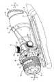
図面を参照すると、照準器10が備わっていて、それは、ハウジング12、光学列(optics train)14、調節系16、および照明系18を含む。ハウジング12は銃器20に選択的に取り付けられていても良く、光学列14、調節系16および照明系18を支えていても良い。光学列14は、ハウジング12と協働し、目標物の拡大像を提供する。一方、調節系16は、ハウジング12に対して光学列14の配置合わせし、光学列14を銃器20に対して適切に調節する。ある形態において、光学列14は、目標物の視野サイズの6倍に実質的に等しいサイズまで、目標物を拡大する。(すなわち、倍率6倍)照明系18は光学列14と協働し、レチクルパターン22を照らして照準器10および銃器20に対してターゲットを合わせる際に支援する。Referring to the drawings, ansight 10 is provided that includes ahousing 12, anoptics train 14, anadjustment system 16, and anillumination system 18. Thehousing 12 may be selectively attached to the firearm 20 and may support theoptical train 14, theadjustment system 16 and theillumination system 18. Theoptical train 14 cooperates with thehousing 12 to provide a magnified image of the target. On the other hand, theadjustment system 16 aligns theoptical row 14 with respect to thehousing 12 and appropriately adjusts theoptical row 14 with respect to the firearm 20. In one form, theoptical array 14 expands the target to a size substantially equal to six times the target field size. Theillumination system 18 cooperates with theoptical train 14 to assist in aligning the target with thesight 10 and the firearm 20 by illuminating thereticle pattern 22.

ハウジング12は、アイピース(接眼レンズ)26を備えた本体24を含む。本体24は、銃器20にハウジング12を取り付けるときに使われる一連のネジ穴28、および長軸32を持つ内部空間30を含む。本体24の第1端部34は実質的に円形状部分を含み、ハウジング12の内部空間30と通じている。第2端部36は、第1端部34から本体24の反対側に一般に配置され、同様に円形の断面形状部を含む。テーパー状口径部分38は、第1端部34と第2端部36の間に配置され、テーパー状口径部分38の形状を決める階段状表面40を含む。Thehousing 12 includes amain body 24 provided with aneyepiece 26. Thebody 24 includes aninterior space 30 having a series of screw holes 28 and along axis 32 that are used when thehousing 12 is attached to the firearm 20. Thefirst end 34 of thebody 24 includes a substantially circular portion and communicates with theinterior space 30 of thehousing 12. The second end 36 is generally disposed on the opposite side of thebody 24 from thefirst end 34 and similarly includes a circular cross-section. The taperedcaliber portion 38 is disposed between thefirst end 34 and the second end 36 and includes a steppedsurface 40 that defines the shape of the taperedcaliber portion 38.

本体24の第1端部34は、第2端部36の出口瞳孔より大きい直径を有する入口瞳孔を含む。第1端部34の入口瞳孔は、照準器10に入る光量を決定し、出口瞳孔と協働し照準器10に所望の倍率を持たせる。ある形態において、入口瞳孔は、出口瞳孔の直径より実質的に6倍大きい直径を含む。このような形態は「6x倍率」を持つ照準器10を提供する。出口瞳孔は入口瞳孔より6倍であると記載されていても、出口瞳孔を大きくして、使用者の眼を照準器10と合わせても良い。第1端部34は、周辺光による光学列14上にグレア(眩しい光)の発生を防ぐために、目標物に向かって底部44より大きく伸びる切頂部分42を含んでも良い。Thefirst end 34 of thebody 24 includes an entrance pupil having a larger diameter than the exit pupil of the second end 36. The entrance pupil of thefirst end 34 determines the amount of light entering thesight 10 and cooperates with the exit pupil to cause thesight 10 to have a desired magnification. In some forms, the entrance pupil includes a diameter that is substantially six times greater than the diameter of the exit pupil. Such a configuration provides ansight 10 with “6 × magnification”. Even though it is described that the exit pupil is six times larger than the entrance pupil, the exit pupil may be enlarged and the user's eyes may be aligned with thesight 10. Thefirst end 34 may include atruncated portion 42 that extends larger than the bottom 44 toward the target in order to prevent glare (dazzling light) from occurring on theoptical array 14 due to ambient light.

本体24は調節系16を支持し、そこに調節系16の部分を操作可能に受ける少なくとも1つの穴46を含んでも良い。本体24はまた、調節系16と協働し、ターゲットに対してレチクルパターン22の位置を調節する内部弓形面48を含んでも良い。Thebody 24 may support theadjustment system 16 and include at least onehole 46 in which the portion of theadjustment system 16 is operably received. Thebody 24 may also include an internal arcuate surface 48 that cooperates with theadjustment system 16 to adjust the position of thereticle pattern 22 relative to the target.

本体24は、アイピース26と協働しアイピース26に対して本体24を位置合わせし、アイピース26に対して本体24を取り付ける固定部50を含んでも良い。固定部50は、アイピース26と相互作用するために本体24から伸びるタブ52を含んでも良い。接合フランジ面の間をシールするために、本体24とアイピース26の間に環状シール53が配置されていても良い。たとえば、そのようなシールをするために、環状シール53は固定部50内に配置されても良い。本体24は、タブ52および環状シール53を有する固定部50を含むと記載されているとしても、本体24は、追加的に、および/または代替的に本体24をアイピース26に取りつける任意の固定部を含むことができる。たとえば、固定部50は、アイピース26を通して受け取られ本体24に挿入され、本体24に対してアイピース26を位置合わせし、本体24にアイピース26を取りつける一連の留め具54(図1)を含むことができる。留め具54が本体24にアイピース26を取りつけるために使われる場合、本体24は、留め具54を嵌合して受ける一連のネジ穴56を含んでも良い。Themain body 24 may include a fixing portion 50 that cooperates with theeyepiece 26 to align themain body 24 with respect to theeyepiece 26 and attach themain body 24 to theeyepiece 26. The securing portion 50 may include a tab 52 that extends from thebody 24 to interact with theeyepiece 26. An annular seal 53 may be disposed between themain body 24 and theeyepiece 26 in order to seal between the joint flange surfaces. For example, the annular seal 53 may be disposed in the fixed portion 50 in order to make such a seal. Even though thebody 24 is described as including a securing portion 50 having a tab 52 and an annular seal 53, thebody 24 may additionally and / or alternatively be any securing portion that attaches thebody 24 to theeyepiece 26. Can be included. For example, the anchor 50 includes a series of fasteners 54 (FIG. 1) that are received through theeyepiece 26 and inserted into thebody 24 to align theeyepiece 26 with thebody 24 and attach theeyepiece 26 to thebody 24. it can. When the fastener 54 is used to attach theeyepiece 26 to thebody 24, thebody 24 may include a series of screw holes 56 that fit and receive the fastener 54.

アイピース26は、本体24によって嵌合して受け取られ、上述したように固定部50によりそこへ取り付けられても良い。そのようなものとして、アイピース26は、留め具54を嵌合して受けるネジ穴58(示されず)を同様に含んでも良い。Theeyepiece 26 may be received and fitted by thebody 24 and attached thereto by the fixing part 50 as described above. As such,eyepiece 26 may similarly include a threaded hole 58 (not shown) that fits and receives fastener 54.

アイピース26は、アイピース26は本体24に組み立てられるとき、本体24の長軸32と同軸上に合わせられる長軸60を含む。アイピース26は、第1端部62と反対側のアイピース26の端部に配置される第2端部64および固定部50により、本体24へ取り付けられる第1端部62を含む。第1端部62は内部弓形面66を含んでも良い。アイピース26が本体24へ取り付けられるとき、本体24の内部弓形面48と合わさる内部弓形面66を含んでも良い。内部弓形面66は本体24の内部弓形面48と協働し球面シートを作り、それは光学列14の調節中にハウジング12に対して光学列14の部分を動かすことを可能にする。さらに以下に記載するように、ハウジング12に対して光学列14の部分を動かすことにより、ハウジング12に対してレチクルパターン22を調節することができ、この結果、銃器20に対して照準器10を調節することが可能となる。固定リング72が、照明系18に隣接したアイピース26の末端部に配置されていても良く、たとえば、照明系18の回転ダイヤルのような調節機構を保持するために使うこともできる。第1端部62はまた、少なくとも照明系18の部分を受ける凹部68を含んでも良い。Theeyepiece 26 includes a major axis 60 that is coaxially aligned with themajor axis 32 of thebody 24 when theeyepiece 26 is assembled to thebody 24. Theeyepiece 26 includes a first end 62 that is attached to thebody 24 by asecond end 64 and a securing portion 50 that are disposed at the end of theeyepiece 26 opposite the first end 62. The first end 62 may include an internal arcuate surface 66. Wheneyepiece 26 is attached tobody 24, it may include an internal arcuate surface 66 that mates with internal arcuate surface 48 ofbody 24. The inner arcuate surface 66 cooperates with the inner arcuate surface 48 of thebody 24 to create a spherical sheet that allows the portion of theoptical row 14 to move relative to thehousing 12 during adjustment of theoptical row 14. As described further below, thereticle pattern 22 can be adjusted relative to thehousing 12 by moving portions of theoptical row 14 relative to thehousing 12, resulting in theaimer 10 being positioned relative to the firearm 20. It becomes possible to adjust. Afixation ring 72 may be disposed at the distal end of theeyepiece 26 adjacent to theillumination system 18 and may be used to hold an adjustment mechanism such as, for example, a rotating dial of theillumination system 18. The first end 62 may also include arecess 68 that receives at least a portion of theillumination system 18.

特に図2および3を参照すると、光学列14は、対物レンズ系74、像正立系76、および接眼レンズ系78を含むように示される。対物レンズ系74は望遠対物レンズであり、前方の正のパワーレンズ群75および後方の負のパワーレンズ群77を含む。前方の正のパワーレンズ群75は、一般に本体24の第1端部34に隣接して配置され、ピッタリと接着した凸平単レンズ96によってともに固定された、実質的に複凸レンズおよび実質的に凹凸レンズを有する凸平複レンズ80を含む。レンズ80、96は、ハウジング12の本体24に対してレンズ80、96を位置合わせし取り付けるために、ネジ切り固定リング82および/または接着剤により本体24の第1端部34内に固定されていても良い。With particular reference to FIGS. 2 and 3, theoptical train 14 is shown to include anobjective lens system 74, animage erecting system 76, and an eyepiece system 78. Theobjective lens system 74 is a telephoto objective lens, and includes a front positive power lens group 75 and a rear negative power lens group 77. The front positive power lens group 75 is generally disposed adjacent to thefirst end 34 of themain body 24 and is fixed together by a convexsingle lens 96 that is closely bonded and substantially biconvex lenses and substantially A convex flat double lens 80 having a concave-convex lens is included. Thelenses 80, 96 are secured within thefirst end 34 of thebody 24 by a threaded retainingring 82 and / or adhesive to align and attach thelenses 80, 96 to thebody 24 of thehousing 12. May be.

後方の負のパワーレンズ群77は一般に前方の正のパワーレンズ群75と本体24の第2端部36との間に配置され、凹平単レンズ98および凹凸複レンズ100を含む。前方の正のパワーレンズ群75と同様に、後方の負のパワーレンズ群77の単レンズ98および複レンズ100は、ネジ切り固定部83および/または接着剤によりハウジング12の本体24内に保持され位置合わせされても良い。The rear negative power lens group 77 is generally disposed between the front positive power lens group 75 and the second end 36 of themain body 24, and includes a concave flat single lens 98 and a concave / convexdouble lens 100. Similar to the front positive power lens group 75, the single lens 98 and thedouble lens 100 of the rear negative power lens group 77 are held in themain body 24 of thehousing 12 by the threaded fixing portion 83 and / or adhesive. It may be aligned.

像正立系76は、一般に対物レンズ系74および接眼レンズ系78の間のハウジング12内に配置される。像正立系76は、ハウジング84、ルーフプリズム86、およびミラープリズム88を含み、それらは協働しペシャンプリズムアセンブリを形成する。像正立系76は、対物レンズ系74および接眼レンズ系78と協働し、ハウジング12、すなわち銃器20に対して視覚目標物の像を適切に方向合わせできる。たとえば、像は本体24の長手方向軸32に沿って進み、アイピース26で見られる前にペシャンプリズムアセンブリの光路に沿って進む。像正立系76はまた、照明系18と協働し、アイピースレンズ90で表示されるレチクルパターン22の全体形状およびサイズを与える。ペシャンプリズムアセンブリは好適には共同出願US特許4,806,007に開示されたタイプであり、その開示は参照することによりここに含まれる。Theimage erecting system 76 is generally disposed in thehousing 12 between theobjective lens system 74 and the eyepiece system 78. Theimage erecting system 76 includes ahousing 84, aroof prism 86, and amirror prism 88 that cooperate to form a Pechan prism assembly. Theimage erecting system 76 cooperates with theobjective lens system 74 and the eyepiece lens system 78 to properly orient the image of the visual target relative to thehousing 12, that is, the firearm 20. For example, the image travels along thelongitudinal axis 32 of thebody 24 and travels along the optical path of the Pechan prism assembly before being viewed at theeyepiece 26.Image erecting system 76 also cooperates withillumination system 18 to provide the overall shape and size ofreticle pattern 22 displayed byeyepiece lens 90. The Pechan prism assembly is preferably of the type disclosed in joint application US Pat. No. 4,806,007, the disclosure of which is hereby incorporated by reference.

像正立系76からの像は、アイピース26に隣接して配置された接眼レンズ系78によって受け取られる。接眼レンズ系78は、対物レンズ系74から光学照準器10の対向端部に一般に配置され、アイピースレンズ90を含む。それは両凸単レンズや実質的に複凸型レンズ、および複接眼レンズ92であっても良い。以下に、アイピースレンズ90は複凸アイピースレンズ90として記載されている。複接眼レンズ92は、適切な接着剤によって共に固定された実質的に複凹レンズおよび実質的に複凸レンズを含んでも良い。複凸アイピースレンズ90および複接眼レンズ92はネジ切り固定リング94によりハウジング12のアイピース26に対して所望の位置において固定されても良い。ネジ切り固定リング94は開示されているが、複凸アイピースレンズ90および複接眼レンズ92は、代替的におよび/または付加的に、接着剤を使ってハウジング12のアイピース26に取りつけることもできる。An image from theimage erecting system 76 is received by an eyepiece system 78 disposed adjacent to theeyepiece 26. The eyepiece system 78 is generally disposed at the opposite end of theoptical sight 10 from theobjective lens system 74 and includes aneyepiece lens 90. It may be a biconvex single lens, a substantially biconvex lens, and adouble eyepiece lens 92. In the following, theeyepiece lens 90 is described as abiconvex eyepiece lens 90. Thebicular lens 92 may include a substantially biconcave lens and a substantially biconvex lens secured together by a suitable adhesive. Thebiconvex eyepiece lens 90 and thedouble eyepiece lens 92 may be fixed at a desired position with respect to theeyepiece 26 of thehousing 12 by a threaded fixingring 94. Although a threadedfixation ring 94 is disclosed, thebiconvex eyepiece lens 90 and thedouble eyepiece lens 92 may alternatively and / or additionally be attached to theeyepiece 26 of thehousing 12 using an adhesive.

光学照準器10は視認ターゲット(すなわち、光学照準器10を使わずに見たときのターゲット)の約6倍サイズのターゲット拡大像を与える。ターゲット像を拡大するために光学照準器10の能力を増大すると、遠くのターゲットを拡大する際に光学照準器10の性能を改善し、光学照準器10を使いより遠くのターゲットを拡大することができる。一般的に言えば、このような倍率面の改善はもっと長い焦点長さを持つ対物レンズを導入することによって実現できる。しかし、対物レンズの焦点長さを増大すると、ハウジング12のすべての長さを増大させ、その結果光学照準器10のすべての長さやサイズを増大させる。Theoptical sight 10 provides a target magnified image that is approximately six times the size of the visual target (ie, the target when viewed without the optical sight 10). Increasing the ability of theoptical sight 10 to magnify the target image can improve the performance of theoptical sight 10 when magnifying a far target and use theoptical sight 10 to magnify a far target. it can. Generally speaking, such an improvement in the magnification plane can be realized by introducing an objective lens having a longer focal length. However, increasing the focal length of the objective lens increases all the length of thehousing 12 and consequently increases all the length and size of theoptical sight 10.

上述したように、複数のレンズを使って対物レンズの焦点長さを増大することによって、本発明において6x倍率が達成される。凸平単レンズ96、凹平単レンズ98、および複レンズ100の間で、対物レンズ系74、像正立系76、および接眼レンズ系78と協働すると、ターゲットの視認サイズより6倍大きくターゲットを拡大する光学照準器10が実現できる。特に、前方の正のパワーレンズ群75および後方の負のパワーレンズ群77にレンズ96、98、および100をそれぞれ付加することにより、ハウジングを余り長くせずに、また繁雑にせずに、6x倍率を持つ光学照準器10を実現できる。As described above, 6 × magnification is achieved in the present invention by using multiple lenses to increase the focal length of the objective lens. When cooperating with theobjective lens system 74, theimage erecting system 76, and the eyepiece system 78 between the convex flatsingle lens 96, the concave flat single lens 98, and thedouble lens 100, the target is 6 times larger than the target viewing size. Can be realized. In particular, by addinglenses 96, 98, and 100 to the front positive power lens group 75 and the rear negative power lens group 77, respectively, the 6 × magnification is achieved without making the housing too long or complicated. Theoptical sighting device 10 having the above can be realized.

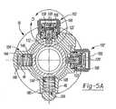
特に図4および5を参照すると、調節系16は調節組立部102、102’ およびバイアス組立部104、104’ を含むように示される。調節組立部102、102’ は、バイアス組立部104、104’ と協働し、ハウジング12に対して像正立系76のハウジング84を選択的に動かす。ハウジング13に対して像正立系76のハウジング84の動作は、ハウジング12に対してルーフプリズム86およびミラープリズム88を動かし、その結果、ハウジング12に対してレチクルパターン22の位置を調節することもできる。ハウジング12に対してレチクルパターン22のこのような調節は、銃器20に対してレチクル22を合わせてウィンデージおよびエレベーションをなくすために使うこともできる。With particular reference to FIGS. 4 and 5, theadjustment system 16 is shown to includeadjustment assemblies 102, 102 'andbias assemblies 104, 104'. Theadjustment assembly 102, 102 ′ cooperates with thebias assembly 104, 104 ′ to selectively move thehousing 84 of theimage erecting system 76 relative to thehousing 12. The movement of thehousing 84 of theimage erecting system 76 relative to thehousing 13 moves theroof prism 86 and themirror prism 88 relative to thehousing 12 and consequently adjusts the position of thereticle pattern 22 relative to thehousing 12. it can. Such adjustment of thereticle pattern 22 relative to thehousing 12 can also be used to align thereticle 22 relative to the firearm 20 to eliminate windage and elevation.

図2および5に示されているように、本発明の光学照準器10は、レチクルパターン22のエレベーションを調節するために、ハウジング12に対して像正立系76のハウジング84を協同して回転する第1のバイアス組立部104および第1の調節組立部102を含む。図2における矢印「X」によって模式的に示されるように、ハウジング84の回転により、軸32、60に実質的に垂直な方向においてレチクルパターン22を動かすことができる。2 and 5, theoptical sight 10 of the present invention cooperates with thehousing 84 of theimage erecting system 76 relative to thehousing 12 to adjust the elevation of thereticle pattern 22. A rotatingfirst bias assembly 104 and afirst adjustment assembly 102 are included. As schematically illustrated by the arrow “X” in FIG. 2, rotation of thehousing 84 can move thereticle pattern 22 in a direction substantially perpendicular to theaxes 32, 60.

図3および5に示されるように、本発明の光学照準器10は、ハウジング12に対して像正立系76のハウジング84をお互いに協働して動かす第2のバイアス組立部104’ および第2の調節組立部102’ を含む。ハウジング12に対して像正立系76のハウジング84の動作は同様にハウジング12に対してレチクルパターン22を動かす。ハウジング12に対するこのようなレチクルパターン22の動作により、ハウジング12に対してレチクルパターン22を適切に合わせ、またこの結果、光学照準器10を銃器20と適切に合わせるために、ウィンデージ調節を行っても良い。図3において矢印「Y」によって図示されているように、レチクルパターン22のこのような動きは軸32、60および矢印Xに対して実質的に垂直である。As shown in FIGS. 3 and 5, theoptical sight 10 of the present invention includes asecond bias assembly 104 ′ and asecond bias assembly 104 ′ that move thehousing 84 of theimage erecting system 76 relative to thehousing 12. 2 adjustment assemblies 102 '. Movement of thehousing 84 of theimage erecting system 76 relative to thehousing 12 similarly moves thereticle pattern 22 relative to thehousing 12. Such movement of thereticle pattern 22 with respect to thehousing 12 allows thereticle pattern 22 to be properly aligned with thehousing 12, and as a result, windage adjustment can be performed to properly align theoptical sight 10 with the firearm 20. good. Such movement ofreticle pattern 22 is substantially perpendicular toaxes 32, 60 and arrow X, as illustrated by arrow “Y” in FIG.

第1の調節組立部102は第2の調節組立部102’ と実質的に一致していて、第1のバイアス組立部104は第2のバイアス組立部104’ と実質的に一致しているので、第2の調節組立部102’ および第2のバイアス組立部104’ の詳細な説明は前述の通りである。Since thefirst adjustment assembly 102 is substantially coincident with the second adjustment assembly 102 'and thefirst bias assembly 104 is substantially coincident with the second bias assembly 104'. The detailed description of the second adjustment assembly 102 'and the second bias assembly 104' has been described above.

図4および5を参照すると、第1の調節組立部102は、キャップ106、調節ノブ108、戻り止め組立部109、中空アダプタ110、および結合ピン112を含むように示されている。キャップ106は、ハウジング12に選択的に取り付けることができ、中空アダプタ110と噛みあわせするための一連のネジ山114を含んでも良い。キャップ106は、一般に調節ノブ108および中空アダプタ110の一部を受ける内部空間116を含む。キャップ106はハウジング112にキャップ106を選択的に取り付ける一連のネジ山114を含むとして示され記載されているが、キャップ106は、たとえば、スナップ式および/またはメカニカルファスナー式のような、ハウジング12にキャップ106を選択的に取り付けることができる任意の形状を含む。With reference to FIGS. 4 and 5, thefirst adjustment assembly 102 is shown to include acap 106, anadjustment knob 108, adetent assembly 109, ahollow adapter 110, and acoupling pin 112. Thecap 106 can be selectively attached to thehousing 12 and may include a series ofthreads 114 for mating with thehollow adapter 110. Thecap 106 generally includes aninterior space 116 that receives theadjustment knob 108 and a portion of thehollow adapter 110. Although thecap 106 is shown and described as including a series ofthreads 114 that selectively attach thecap 106 to thehousing 112, thecap 106 may be attached to thehousing 12, for example, snap and / or mechanical fasteners. Includes any shape to which thecap 106 can be selectively attached.

調節ノブ108は、キャップ106の内部空間116内に一般に配置され、一連のファスナー121および/または接着剤によりプラグ118に取り付けられたトップキャップ120および中空アダプタ110に回転自在に取り付けられるプラグ118を含む。プラグ118は、中空アダプタ110と嵌合して受けられるネジ付き伸長部122を含み、その結果、プラグ118およびトップキャップ120の回転により、プラグ118およびトップキャップ120が中空アダプタ110に対するプラグ118の回転方向に依存してハウジング12の方へまたはハウジング12から動く。Theadjustment knob 108 is generally disposed within theinterior space 116 of thecap 106 and includes atop cap 120 attached to theplug 118 by a series offasteners 121 and / or adhesive and aplug 118 that is rotatably attached to thehollow adapter 110. .Plug 118 includes a threadedextension 122 that is received in mating engagement withhollow adapter 110 such that rotation ofplug 118 andtop cap 120 causes plug 118 andtop cap 120 to rotateplug 118 relative tohollow adapter 110. Depending on the direction, it moves toward or away from thehousing 12.

戻り止め組立部109は、プラグ118を通して形成される放射状十字ボア111に配置されても良いし、戻り止めピン115にバイアス力を与えるスプリング113を含んでも良い。スプリング113によって戻り止めピン115に与えられたバイアスは、十字ボア111から外側に戻り止めピン115を強く押し、中空アダプタ110の側壁とかみ合わせる。複数の軸方向に伸びる溝117が、中空アダプタ110の内面の周りに間隙をおいた間隔で周辺に配置されていても良い。その結果、光学照準器10の較正を容易にするために戻り止めピン115が隣接する溝117の方へ動くときに、螺合してプラグ118を前進させるかまたは後退させながら、作業者は物理的または可聴式の「クリック音」を感知することができる。Thedetent assembly 109 may be disposed in a radial cross bore 111 formed through theplug 118 or may include aspring 113 that provides a biasing force to the detent pin 115. The bias applied to the detent pin 115 by thespring 113 strongly pushes the detent pin 115 outward from the cross bore 111 and engages with the side wall of thehollow adapter 110. A plurality of axially extendinggrooves 117 may be disposed around the inner surface of thehollow adapter 110 with a gap therebetween. As a result, when the detent pin 115 moves toward theadjacent groove 117 to facilitate calibration of theoptical sight 10, the operator can physically move while theplug 118 is advanced or retracted. A conscious or audible “click” can be sensed.

中空アダプタ110は、ハウジング12に取り付けられ、ハウジング12のネジ穴126内に嵌合して受けられる一連の雄ネジ124を含んでも良い。中空アダプタ110はネジ接続によりハウジング12に取り付けられているように記載され示されているが、中空アダプタ110は、たとえばエポキシ接着および/または圧入のような任意の適切な手段によりハウジング12に取り付けることもできる。Thehollow adapter 110 may include a series ofmale threads 124 that are attached to thehousing 12 and are received within a threaded hole 126 of thehousing 12. Although thehollow adapter 110 is described and shown as being attached to thehousing 12 by a screw connection, thehollow adapter 110 may be attached to thehousing 12 by any suitable means such as, for example, epoxy bonding and / or press fit. You can also.

中空アダプタ110は、プラグ118のネジ付き伸長部122を嵌合して受ける一連のネジ山130を持つ中心ボア128を含む。上述したように、調節ノブ108に力が加わり、プラグ118およびネジ付き伸長部122が中空アダプタ110に対して回転するときに、プラグ118およびネジ付き伸長部122は、プラグ118のネジ付き伸長部122および中空アダプタ110のネジ山130の間におけるかみ合いにより、ハウジング12の方へ、またはハウジング12から離れて動く。中空アダプタ110は、中空アダプタ110およびハウジング12の間における結合を密封するシール134を受けるために、外表面に形成された少なくとも1つの窪み132を含んでも良い。同様の窪み136が、調節ノブ108のトップキャップ120に隣接した中空アダプタ110に形成されても良いし、同様に調節ノブ108のトップキャップ120および中空アダプタ110の間における結合を密封するシール138を受けても良い。窪み132、136は中空アダプタ110と一体化して形成されても良いし、および/または中空アダプタ110の外表面において機械加工されても良い。シール134、138は、たとえばOリングのような任意の適切なシールであっても良い。Thehollow adapter 110 includes acentral bore 128 with a series of threads 130 that fit and receive the threadedextension 122 of theplug 118. As described above, when force is applied to theadjustment knob 108 and theplug 118 and threadedextension 122 rotate relative to thehollow adapter 110, theplug 118 and threadedextension 122 become threaded extensions of theplug 118. The engagement between 122 and the thread 130 of thehollow adapter 110 moves toward or away from thehousing 12. Thehollow adapter 110 may include at least oneindentation 132 formed in the outer surface to receive aseal 134 that seals the bond between thehollow adapter 110 and thehousing 12. Asimilar indent 136 may be formed in thehollow adapter 110 adjacent to thetop cap 120 of theadjustment knob 108, as well as aseal 138 that seals the bond between thetop cap 120 of theadjustment knob 108 and thehollow adapter 110. You may receive it. Therecesses 132, 136 may be formed integrally with thehollow adapter 110 and / or machined on the outer surface of thehollow adapter 110. Theseals 134, 138 may be any suitable seal such as an O-ring.

係合ピン112は、プラグ118の一般にネジ付き伸長部122および内に受けられ、取り付け部140の末端部から伸びる係合部142およびプラグ118のネジ付き伸長部122内で回転自在に受けられる取り付け部140を含む。ネジ付き伸長部122はプラグ118とともに動くために固定される。Theengagement pin 112 is received within the generally threadedextension 122 and of theplug 118 and is mounted for rotation within the threadedextension 122 of theengagement portion 142 and theplug 118 extending from the distal end of theattachment portion 140.Part 140. The threadedextension 122 is fixed for movement with theplug 118.

係合部142は、取り付け部140から伸び、像正立系76のハウジング84と接触している。第1のバイアス組立部104は、係合ピン112の係合部142と係合して、像正立系76のハウジング84にバイアスをかける。第1のバイアス組立部104は、ハウジング12のボア146内に配置されたバイアス部材144を含む。バイアス部材144は像正立系76のハウジング84と接触していても良いし、或いは代替的に、キャップ148は一般に、像正立系76のハウジング84およびバイアス部材144との間に配置されていても良い。どちらの形態においても、バイアス部材144は、ハウジング84を係合ピン112の係合部142と係合して像正立系76のハウジング84に力を加える。バイアス部材144は、たとえばコイルスプリングまたは線状スプリングのような任意の適切なスプリングであっても良い。The engagingportion 142 extends from theattachment portion 140 and is in contact with thehousing 84 of theimage erecting system 76. The firstbias assembly portion 104 engages with the engagingportion 142 of theengaging pin 112 to bias thehousing 84 of theimage erecting system 76. Thefirst bias assembly 104 includes abias member 144 disposed within thebore 146 of thehousing 12. Thebias member 144 may be in contact with thehousing 84 of theimage erecting system 76, or alternatively, thecap 148 is generally disposed between thehousing 84 and thebias member 144 of theimage erecting system 76. May be. In either form, thebias member 144 applies a force to thehousing 84 of theimage erecting system 76 by engaging thehousing 84 with the engagingportion 142 of theengaging pin 112. Thebias member 144 may be any suitable spring such as a coil spring or a linear spring.

像正立系76のハウジング84は係合ピン112の係合部142と係合してバイアスされるので、中空アダプタ110に対して係合ピン112の動作により、ハウジング12に対して像正立系76のハウジング84を動かす。中空アダプタ110の底部および係合部142の間にボールベアリング150を配置すると、中空アダプタ110に対して係合ピン112のそのような動きを弱める可能性がある。調節系16の静かな操作を保証するために係合ピン112がハウジング12の方へ、およびハウジング12から離れて動かされるとき、ボールベアリング150は、係合部142および中空アダプタ110の間にシール(気密)を提供しても良いし、係合ピン112の動きを弱める可能性もある。Since thehousing 84 of theimage erecting system 76 is biased by engaging with the engagingportion 142 of theengaging pin 112, the image erecting with respect to thehousing 12 is performed by the operation of theengaging pin 112 with respect to thehollow adapter 110. Thehousing 84 of thesystem 76 is moved. Placing theball bearing 150 between the bottom of thehollow adapter 110 and theengagement portion 142 may weaken such movement of theengagement pin 112 relative to thehollow adapter 110. When theengagement pin 112 is moved toward and away from thehousing 12 to ensure quiet operation of theadjustment system 16, the ball bearing 150 seals between theengagement portion 142 and thehollow adapter 110. (Airtightness) may be provided, and the movement of theengagement pin 112 may be weakened.

図4および5を続けて参照すると、調節系16の操作が詳細に記載される。ハウジング12に対してレチクルパターン22のエレベーションを調節するために、キャップ106はハウジング12との係合を外される。ある形態において、キャップ106はハウジング12に螺合して取り付けられる。その結果、キャップ106をハウジング12との係合を外すために、ハウジング12に対してキャップ106を回転するためにキャップ106に力が加えられる。キャップ106がハウジング12に対して十分に回転されると、キャップ106はハウジング12と係合を外される可能性がある。With continued reference to FIGS. 4 and 5, the operation of theadjustment system 16 will be described in detail.Cap 106 is disengaged fromhousing 12 to adjust the elevation ofreticle pattern 22 relative tohousing 12. In one form, thecap 106 is screwed onto thehousing 12. As a result, a force is applied to thecap 106 to rotate thecap 106 relative to thehousing 12 to disengage thecap 106 from thehousing 12. If thecap 106 is fully rotated relative to thehousing 12, thecap 106 may be disengaged from thehousing 12.

ハウジング12とキャップ106の係合を外すと、調節ノブ108のトップキャップ120が露出する。調節用トップキャップ120を露出させると、トップキャップ120により調節ノブ108のプラグ118に力を加えることができる。中空アダプタ110に対してネジ付き伸長部122およびプラグ118を回転するために、回転力が調節プラグ118のトップキャップ120へ一般に加えられる。中空アダプタ110に対してネジ付き伸長部122およびプラグ118の回転により、中空アダプタ110の中心ボア128に対してネジ付き伸長部122を動かすことができる。When thehousing 12 and thecap 106 are disengaged, thetop cap 120 of theadjustment knob 108 is exposed. When theadjustment top cap 120 is exposed, a force can be applied to theplug 118 of theadjustment knob 108 by thetop cap 120. A rotational force is generally applied to thetop cap 120 of theadjustment plug 118 to rotate the threadedextension 122 and theplug 118 relative to thehollow adapter 110. Rotation of the threadedextension 122 and plug 118 relative to thehollow adapter 110 can move the threadedextension 122 relative to thecentral bore 128 of thehollow adapter 110.

上述したように、中心ボア128はネジ付き伸長部122を係合するネジ山130を含んでも良い。その結果、プラグ118およびネジ付き伸長部122はハウジングに対して回転するので、ネジ付き伸長部122の回転方向に依存して、ネジ付き伸長部122および中心ボア128のネジ山130の間における係合のおかげで、プラグ118、トップキャップ120およびネジ付き伸長部122は、中空アダプタ110の方へ、またはアダプタ110から離れて動かすことができる。係合ピン112は、調節ノブ108のネジ付き伸長部122に取り付けられ、その結果、プラグ118、トップキャップ120、およびネジ付き伸長部122が中空アダプタ110に対して動くとき、プラグ118、トップキャップ120、およびネジ付き伸長部122と一緒に動く。As described above, thecentral bore 128 may include a thread 130 that engages the threadedextension 122. As a result, theplug 118 and threadedextension 122 rotate relative to the housing, so that the engagement between the threadedextension 122 and the thread 130 of thecentral bore 128 depends on the direction of rotation of the threadedextension 122. Thanks to this, theplug 118,top cap 120 and threadedextension 122 can be moved toward or away from thehollow adapter 110. Theengagement pin 112 is attached to the threadedextension 122 of theadjustment knob 108 so that when theplug 118,top cap 120, and threadedextension 122 move relative to thehollow adapter 110, theplug 118, top cap. 120 and moves with threadedextension 122.

トップキャップ120へ加えられる力によりネジ付き伸長部122が中空アダプタ110の方へ動かされるとき、係合ピン112は、像正立系76のハウジング84へ「Z」方向(図5B)に力を加える。像正立系76のハウジング84へ「Z」方向における力が加えられると、ハウジング84は、第1のバイアス組立部104によってハウジング84に与えられるバイアスに逆らって動くことができる。このようなハウジング84の動きは、ハウジング12に対してZ方向においてレチクルパターン22を同時に動かし、その結果、ハウジング12に対してレチクルパターン22のエレベーションを調節する。When the threadedextension 122 is moved toward thehollow adapter 110 by the force applied to thetop cap 120, theengagement pin 112 exerts a force in the "Z" direction (Fig. 5B) on thehousing 84 of theimage erecting system 76. Add. When a force in the “Z” direction is applied to thehousing 84 of theimage erecting system 76, thehousing 84 can move against the bias provided to thehousing 84 by thefirst bias assembly 104. Such movement of thehousing 84 simultaneously moves thereticle pattern 22 in the Z direction relative to thehousing 12, and as a result, adjusts the elevation of thereticle pattern 22 relative to thehousing 12.

反対方向においてトップキャップ120へ力が加えられるとき、ネジ付き伸長部122および係合ピン112は、Z方向において中空アダプタ110から離れて動く。像正立系76のハウジング84は、第1バイアス組立部104のバイアス部材144によってハウジング84に与えられる力のおかげで、Z方向と反対方向に同様に動く。上述したように、Z方向と一般的に反対方向におけるネジ付き伸長部122および係合ピン112の動作にもかかわらず、第1のバイアス組立部104のバイアス部材144によって像正立系76のハウジング84に与えられる力のおかげで、像正立系76のハウジング84は、ネジ付き伸長部122の係合部142と接触して維持される。When a force is applied to thetop cap 120 in the opposite direction, the threadedextension 122 and theengagement pin 112 move away from thehollow adapter 110 in the Z direction. Thehousing 84 of theimage erecting system 76 moves similarly in the opposite direction to the Z direction due to the force applied to thehousing 84 by thebias member 144 of thefirst bias assembly 104. As described above, the housing of theimage erecting system 76 by thebias member 144 of thefirst bias assembly 104 despite the operation of the threadedextension 122 and theengagement pin 112 in a direction generally opposite to the Z direction. Thanks to the force applied to 84, thehousing 84 of theimage erecting system 76 is maintained in contact with theengagement portion 142 of the threadedextension 122.

レチクルパターン22のエレベーションがハウジング12に対して調節されるとき、キャップ106は調節ノブ108および中空アダプタ110の上に配置されても良いし、ハウジング12に再取り付けされても良い。ハウジング12へキャップ106の取り付けは、調節ノブ108のさらなる操作を防ぎ、その結果、キャップ106がハウジング12からもう一度取り外されるまで、レチクルパターン22のエレベーションのさらなる調節を防ぐのに役立つ。他の言葉で言えば、キャップ106は、エレベーション調節が望まれないとき、中空アダプタ110に対してプラグ118およびネジ付き伸長部122の回転から発生する不注意な力がトップキャップ120へ加えられることを防ぐ。Z方向と実質的に垂直方向において、ハウジング12に対してレチクルパターン22を動かすことによって、ウィンデージを調節するために、同様のアプローチが第2の調節組立部102’ および第2バイアス組立部104’ に行われても良い。When the elevation of thereticle pattern 22 is adjusted relative to thehousing 12, thecap 106 may be placed over theadjustment knob 108 and thehollow adapter 110, or may be reattached to thehousing 12. Attachment of thecap 106 to thehousing 12 helps prevent further manipulation of theadjustment knob 108 and, as a result, prevent further adjustment of the elevation of thereticle pattern 22 until thecap 106 is removed from thehousing 12 again. In other words, thecap 106 applies inadvertent force to thetop cap 120 resulting from rotation of theplug 118 and threadedextension 122 relative to thehollow adapter 110 when elevation adjustment is not desired. To prevent that. In order to adjust the windage by moving thereticle pattern 22 relative to thehousing 12 in a direction substantially perpendicular to the Z direction, a similar approach is used for the second adjustment assembly 102 'and the second bias assembly 104'. May be done.

特に図1−4Bを参照すると、照明系18はハウジング12のアイピース26に取り付けられた蛍光性ファイバー152を含むように示されている。蛍光性ファイバー152は、アイピース26の外表面の周囲を巻いているとして示されていて、アイピース26の窪み68内で一般に受けられる。蛍光性ファイバー152は、周辺光を捕えても良く、所定の色(たとえば、赤または黄色)で周辺光を照らし、また蛍光性ファイバー152の長さに沿って周辺光を導いても良い。蛍光性ファイバー152は、好適には共同出願US特許4,806,007および6,807,742に開示されたタイプであり、その開示は参照することにより本発明に含まれる。With particular reference to FIGS. 1-4B, theillumination system 18 is shown to include afluorescent fiber 152 attached to theeyepiece 26 of thehousing 12. Thefluorescent fiber 152 is shown as winding around the outer surface of theeyepiece 26 and is generally received within therecess 68 of theeyepiece 26. Thefluorescent fiber 152 may capture ambient light, illuminate the ambient light with a predetermined color (eg, red or yellow), and may guide the ambient light along the length of thefluorescent fiber 152. Thefluorescent fiber 152 is preferably of the type disclosed in joint applications US Pat. Nos. 4,806,007 and 6,807,742, the disclosure of which is hereby incorporated by reference.

蛍光性ファイバー152は、ファイバー152がアイピース26の全周囲を巻くようにハウジング12のアイピース26を軸方向に取り囲んでも良い。(すなわち、アイピース26の外表面の周り360度包まれている。)蛍光性ファイバー152は、レチクルパターン22を照らすために像正立系76の方へ一般に導かれる、アイピース26内に配置された末端部を含んでも良い。たとえば、蛍光性ファイバー152は、レチクルパターン22を照らすためにミラープリズム88に取り付けられた、アイピース26の窪み68から伸びる末端部154(図3)を含んでも良い。操作中、蛍光性ファイバー152は、周辺光を受け、蛍光性ファイバー152の長さに沿って周辺光を一般に末端部154の方へ導く。蛍光性ファイバー152の末端部154に達すると、光はレチクルパターン22を照らすためにミラープリズム88に供給される。共同出願US特許4,806,007に記載されているように、蛍光性ファイバー152からの光がミラープリズム88の刻み部だけを照らすように、レチクルパターン22はミラープリズム88の面に刻まれても良い。言い換えれば、蛍光性ファイバー152からの光は、刻まれたミラープリズム88の部分でミラープリズム88を通して伝達されるだけであり、その結果伝達部分だけはアイピースレンズ90で視認される。レチクルパターン22はその結果、ミラープリズム88の刻み部の全体形状やサイズによって決められる。蛍光性ファイバー152は、蛍光性ファイバー152の長さに沿って末端部154の方へ光を集め導くので、蛍光性ファイバー152は、周辺光をつかまえ、蛍光性ファイバー152の長さに沿って周辺光を導く導管と考えて良い。Thefluorescent fiber 152 may axially surround theeyepiece 26 of thehousing 12 so that thefiber 152 wraps around theentire eyepiece 26. (Ie, wrapped 360 degrees around the outer surface of eyepiece 26).Fluorescent fiber 152 is disposed withineyepiece 26, which is generally directed towardimage erecting system 76 to illuminatereticle pattern 22. An end portion may be included. For example, thefluorescent fiber 152 may include a distal end 154 (FIG. 3) that extends from arecess 68 in theeyepiece 26 that is attached to themirror prism 88 to illuminate thereticle pattern 22. During operation, thefluorescent fiber 152 receives ambient light and directs the ambient light along the length of thefluorescent fiber 152 generally toward the distal end 154. When reaching the end 154 of thefluorescent fiber 152, light is supplied to themirror prism 88 to illuminate thereticle pattern 22. As described in the joint application US Pat. No. 4,806,007, thereticle pattern 22 may be engraved on the surface of themirror prism 88 so that the light from thefluorescent fiber 152 illuminates only the indentations of themirror prism 88. In other words, the light from thefluorescent fiber 152 is only transmitted through themirror prism 88 at the engraved part of themirror prism 88, and as a result, only the transmission part is visually recognized by theeyepiece lens 90. As a result, thereticle pattern 22 is determined by the overall shape and size of the notch portion of themirror prism 88. Thefluorescent fiber 152 collects and directs light toward the end 154 along the length of thefluorescent fiber 152, so that thefluorescent fiber 152 captures ambient light and moves along the length of thefluorescent fiber 152. Think of it as a conduit that guides light.

アイピース26の外表面の周りに蛍光性ファイバー152を完全に包むことにより、露出されるファイバー152の全体表面積を増加させることができ、ファイバー152によって受けることができる光量を最大化できる。さらに、アイピース26の外表面の周りに蛍光性ファイバー152を完全に包むことにより、集光するために露出されるファイバー152の十分な領域を維持しながら、巻かれたファイバー152の幅を小さくできるので、望遠鏡10の全長を短くできる。By completely wrapping thefluorescent fiber 152 around the outer surface of theeyepiece 26, the overall surface area of the exposedfiber 152 can be increased and the amount of light that can be received by thefiber 152 can be maximized. In addition, by completely wrapping thefluorescent fiber 152 around the outer surface of theeyepiece 26, the width of thewound fiber 152 can be reduced while maintaining sufficient area of thefiber 152 exposed to collect light. Therefore, the total length of thetelescope 10 can be shortened.

アイピース26の周りに蛍光性ファイバー152を完全に包むことにより、露出されるファイバー152の表面積を増加させる一方で、巻かれたファイバー152の部分は、ファイバー152によって集められる光を制限するためのコーティング141(図4A)を含んでも良い。たとえば、黒マスクのようなコーティングは、照準器10の底部の巻かれたファイバー152の部分に適用されても良い。コーティングによってファイバー152が集める光を防ぐことができ、一般にコーティングの末端部間の領域に光の収集を制限するためにファイバー152にマスクが適用される。Encapsulating thefluorescent fiber 152 completely around theeyepiece 26 increases the surface area of the exposedfiber 152, while the portion of thewound fiber 152 is a coating to limit the light collected by thefiber 152. 141 (FIG. 4A) may be included. For example, a coating such as a black mask may be applied to the portion of thewound fiber 152 at the bottom of thesight 10. The coating can prevent light collected by thefiber 152, and a mask is applied to thefiber 152 to limit light collection generally to the area between the ends of the coating.

レチクルパターン22の照明により、種々の環境条件において光学照準器10を使用できる。環境条件に応じてレチクルパターン22の照明を調節しても良い。たとえば、暗い環境において、夜間および/または暗い条件下、たとえば建物の中で光学照準器10を使用できるように、レチクルパターン22を照らしても良い。他の条件において、太陽光の中および/または他の照明素子(すなわち、たとえば、戦闘地域におけるブレーキ灯や交通信号灯)の間で光学照準器10を使うときのように、明るい場所でレチクルパターン22を目立つことができるように、レチクルパターン22を照らしても良い。The illumination of thereticle pattern 22 allows theoptical sight 10 to be used in various environmental conditions. The illumination of thereticle pattern 22 may be adjusted according to environmental conditions. For example, thereticle pattern 22 may be illuminated so that theoptical sight 10 can be used in a dark environment at night and / or in dark conditions, for example in a building. In other conditions, thereticle pattern 22 in bright places, such as when using theoptical sight 10 in sunlight and / or between other lighting elements (ie, for example, brake lights or traffic lights in a battle area). Thereticle pattern 22 may be illuminated so that can be conspicuous.

レチクルパターン22の照明は光学照準器10が使用される条件によって一般に決められる。たとえば、夜に光学照準器10を使用するとき、レチクルパターン22がハウジング12の第1端部34で見れるような程度までではなく、使用者がレチクルパターン22を見ることができるようにレチクルパターン22を十分に照らすだけで良い。これに対して、日の当たる条件やたとえば戦闘地域における信号灯のような他の光のもとで光学照準器10を使うとき、レチクルパターン22が明るい光から目立つことができ、ユーザーが明確にレチクルパターン22を視認できる程度以上にレチクルパターン22を照らしても良い。The illumination of thereticle pattern 22 is generally determined by the conditions under which theoptical sight 10 is used. For example, when using theoptical sight 10 at night, thereticle pattern 22 is such that the user can see thereticle pattern 22 rather than to the extent that thereticle pattern 22 is visible at thefirst end 34 of thehousing 12. It is only necessary to fully illuminate. In contrast, when theoptical sight 10 is used under sunlight or other light such as a signal light in a battle area, thereticle pattern 22 can stand out from bright light, and the user can clearly see the reticle. Thereticle pattern 22 may be illuminated more than thepattern 22 can be visually recognized.

ハウジング12のアイピース26によって可動的に支持される回転ダイヤルやスリーブ156により、照明系18においてレチクルパターン22へ供給される光量を調節しても良い。ダイヤル/スリーブ156はハウジング12に対して回転できるように下記で記載されまた図において示されているが、ダイヤル/スリーブ156は、蛍光性ファイバー152を選択的に露出するためにハウジング12に対して、代替的にスライド自在でも良いし、或いは他のやり方で可動できても良い。The amount of light supplied to thereticle pattern 22 in theillumination system 18 may be adjusted by a rotary dial orsleeve 156 movably supported by theeyepiece 26 of thehousing 12. Although the dial /sleeve 156 is described below and shown in the figures such that it can rotate relative to thehousing 12, the dial /sleeve 156 is relative to thehousing 12 to selectively expose thefluorescent fiber 152. Alternatively, it may be slidable or otherwise movable.

回転ダイヤル156は、回転ダイヤル156により周辺光を選択的に取ることができるように形成される開口部158を持つボディ160を含んでも良い。そのボディ160は、たとえば金属のようなリジッド材料から形成されても良く、アイピース26によってハウジング12に対して回転自在に支持されても良い。開口部158は、回転ダイヤルに取り付けられ、回転ダイヤル156と一緒に回転するカバー159を含んでも良い。カバー159は、たとえばクリアプラスチックのような透明または半透明な材料で形成されても良い。カバー159は、クリアプラスチック材料から形成されるとして記載されているが、カバー159は、光を通すことができ、蛍光性ファイバー152によって光を集めることができる任意の材料で形成されても良い。Therotary dial 156 may include abody 160 having anopening 158 formed so that ambient light can be selectively taken by therotary dial 156. Thebody 160 may be formed of a rigid material such as metal, and may be rotatably supported by theeyepiece 26 with respect to thehousing 12. Theopening 158 may include acover 159 attached to the rotary dial and rotating together with therotary dial 156. Thecover 159 may be formed of a transparent or translucent material such as clear plastic. Although thecover 159 is described as being formed from a clear plastic material, thecover 159 may be formed from any material that can transmit light and collect light by thefluorescent fiber 152.

回転ダイヤル156と一緒にカバー159を回転することによって、窪み68をシールし、ダストや他の屑の窪み68への侵入を防ぐことができる。ダストや他の屑が窪み68に入るのを防止することによって、汚染物が蛍光性ファイバー152に入り込むことを防止でき、ファイバー152への損傷を防ぎ、ファイバー152の外表面をきれいに保持することができる。さらに、カバー159を回転ダイヤル156に取り付けることによって、カバー159はダイヤル156と一緒に回転し、ファイバー152から離間される。そのようなものとして、回転ダイヤル156がファイバー152に対して動かされるとき、カバー159およびファイバー152の間に入り込んだ任意のダストおよび/または他の屑によって、ファイバー152の外表面に損傷を与えない。さらに、カバー159は回転ダイヤル156と共に回転するので、ダストおよび/または他の屑が回転ダイヤル156およびカバー159の外表面の間に集まらなくなり、この結果、カバー159に対して回転ダイヤル156の動作によって引き起こされるカバー159の外表面への損傷を防止できる。By rotating thecover 159 together with therotary dial 156, therecess 68 can be sealed, and dust and other debris can be prevented from entering therecess 68. By preventing dust and other debris from entering therecess 68, contaminants can be prevented from entering thefluorescent fiber 152, preventing damage to thefiber 152 and keeping the outer surface of thefiber 152 clean. it can. Further, by attaching thecover 159 to therotary dial 156, thecover 159 rotates with thedial 156 and is separated from thefiber 152. As such, when therotating dial 156 is moved relative to thefiber 152, any dust and / or other debris that has entered between thecover 159 and thefiber 152 will not damage the outer surface of thefiber 152. . Further, since thecover 159 rotates with therotary dial 156, dust and / or other debris does not collect between therotary dial 156 and the outer surface of thecover 159, and as a result, the operation of therotary dial 156 relative to thecover 159 Damage to the outer surface of thecover 159 caused can be prevented.

カバー159および窪み68の間にダストおよび他の屑の侵入を防ぐために、またファイバー152からボディ160を離間するために、一般にボディ160およびアイピース26の外表面の間に一対のOリングシール161を備えても良い。Oリングシール161は、流体、たとえば空気、窒素、および/または水、またはダストおよび/またはよごれのような他の廃物の窪み68への侵入を防ぐ気密シールを窪み68に提供しても良い。たとえば、ある形態において、Oリングシール161は、ボディ160およびアイピース26の間に気密シールを提供する。Oリングシール161は、たとえばゴムのような弾性材料で形成されても良い。A pair of O-ring seals 161 is generally provided between thebody 160 and the outer surface of theeyepiece 26 to prevent ingress of dust and other debris between thecover 159 and therecess 68 and to separate thebody 160 from thefiber 152. You may prepare. The O-ring seal 161 may provide therecess 68 with a hermetic seal that prevents intrusion of fluids such as air, nitrogen, and / or water, or other waste such as dust and / or dirt, into therecess 68. For example, in one form, O-ring seal 161 provides a hermetic seal betweenbody 160 andeyepiece 26. The O-ring seal 161 may be formed of an elastic material such as rubber.

たとえばゴムのような弾性材料169は、一般にボディ160の外表面の周りに形成されても良い。弾性材料169は、ボディ160および回転ダイヤル156のグリップ性および回転性を補助する一連の突起163を含んでも良い。流体および/または他のカスの侵入を防止し、それらが窪み68に入り蛍光性ファイバー152の操作と干渉することを防ぐために、弾性材料169は、弾性材料169がカバー159を完全に取り囲み、またさらにボディ160およびカバー159の間のインターフェースをシールするように、配置されても良い。For example, anelastic material 169 such as rubber may generally be formed around the outer surface of thebody 160. Theelastic material 169 may include a series ofprotrusions 163 that assist in the grip and rotation of thebody 160 and therotary dial 156. In order to prevent intrusion of fluid and / or other debris and prevent them from entering therecess 68 and interfering with the operation of thefluorescent fiber 152, theelastic material 169 completely surrounds thecover 159, and Further, it may be arranged to seal the interface between thebody 160 and thecover 159.

特に図4Bを参照すると、別の照明系18aが光学照準器10と一緒に使用するために提供される。照明系18aに関して照明系18aと関連した部品の構造および機能においてかなり類似していることを考えて、文字の拡張子を含む同様の参照番号は修正された同様の部品を同定するために使われるとしても、同様の部品を同定するために、同様の参照番号が以下および図で使用されている。With particular reference to FIG. 4B, anotherillumination system 18 a is provided for use with theoptical sight 10. Given the similarities in structure and function of parts associated withillumination system 18a with respect toillumination system 18a, similar reference numbers including letter extensions are used to identify similar modified parts. Even so, like reference numerals are used in the following and figures to identify like parts.

照明系18aは、ハウジング12のアイピース26によって回転自在に支持されるボディ160aを含んでも良い。ボディ160aは、ボディ160aの外表面上に形成された弾性材料169aおよび開口部158を含んでも良い。カバー159aは、一般にボディ160a内に受けられても良いし、たとえばクリアプラスチックのような透明材料または半透明材料で形成されても良い。カバー159aはクリアプラスチック材料から形成されていると記載しているとしても、カバー159aは、光を通すことができ、蛍光性ファイバー152によって光を集めることができる任意の材料で形成されても良い。Theillumination system 18 a may include abody 160 a that is rotatably supported by theeyepiece 26 of thehousing 12. Thebody 160a may include anelastic material 169a and anopening 158 formed on the outer surface of thebody 160a.Cover 159a may generally be received withinbody 160a, and may be formed of a transparent or translucent material such as clear plastic, for example. Even though thecover 159a is described as being formed of a clear plastic material, thecover 159a may be formed of any material that can transmit light and collect light by thefluorescent fiber 152. .

流体、たとえば空気、および/または水、またはよごれおよび/またはダストのような他の汚れの窪み68への侵入を防ぐために、Oリングシール161は、一般にボディ160およびアイピース26の間に配置されても良い。Oリングシール161は、カバー159aの内側表面およびアイピース26の外表面の間に配置されても良いし、或いは代替的に、ボディ160aの内側表面およびアイピース26の外表面の間に配置されても良い。どちらの形態においても、Oリングシール161は、カバー159aおよび窪み68の間に気密シールを提供し、流体および/または汚れの窪みへの侵入を防ぐ。さらに、Oリングシール161は、ファイバー152からカバー159aを離間し、カバー159aおよびファイバー152の間の接触を防止する。An O-ring seal 161 is generally disposed between thebody 160 and theeyepiece 26 to prevent entry of fluid, such as air and / or water, or other dirt, such as dirt and / or dust, into therecess 68. Also good. O-ring seal 161 may be disposed between the inner surface ofcover 159a and the outer surface ofeyepiece 26, or alternatively may be disposed between the inner surface ofbody 160a and the outer surface ofeyepiece 26. good. In either configuration, the O-ring seal 161 provides a hermetic seal between thecover 159a and therecess 68 and prevents fluid and / or dirt from entering the recess. Further, the O-ring seal 161 separates thecover 159a from thefiber 152 and prevents contact between thecover 159a and thefiber 152.

上の形態のどちらにおいても、開口部158の幅は、蛍光性ファイバー152に適用されるコーティング141の幅より少し小さくても良く、回転ダイヤル156を用いて蛍光性ファイバー152により集められる光を実質的に防ぐか制限することができる。たとえば、カバー159がコーティング141を妨害するように、回転ダイヤル156を回転する場合、コーティング141は、カバー159下の露出されたファイバー152が完全にコートされ、その結果光を集めることができないように十分な距離だけファイバー152上に伸びることができる。上の形態によって、使用者は、コートされたファイバー152上にカバー159を配置することにより、蛍光性ファイバー152による光収集を実質的に完全に防ぐことができる。In either of the above forms, the width of theopening 158 may be slightly smaller than the width of thecoating 141 applied to thefluorescent fiber 152, and the light collected by thefluorescent fiber 152 using therotating dial 156 is substantially reduced. Can be prevented or restricted. For example, if therotating dial 156 is rotated so that thecover 159 interferes with thecoating 141, thecoating 141 is such that the exposedfiber 152 under thecover 159 is completely coated and consequently cannot collect light. A sufficient distance can extend over thefiber 152. The above configuration allows the user to substantially completely prevent light collection by thefluorescent fiber 152 by placing acover 159 on thecoated fiber 152.

図1に示されるように、回転ダイヤル156は、回転ダイヤル156のボディ160はアイピース26の窪み68をカバーするように、アイピース26に回転自在に取り付けられる。アイピース26に対して回転ダイヤル156の回転は、アイピース26に対して開口部158の同様な回転を引き起こす。回転ダイヤル156は、ボディ160が窪み68を一般にカバーするとき、回転ダイヤル156のボディ160は、窪み68内に一般に配置される蛍光性ファイバー152をカバーする。この位置において、窪み68に入る周辺光が制限され、その結果、蛍光性ファイバー152による周辺光のトラップが制限される。この位置において、蛍光性ファイバー152は限定された光量だけをレチクルパターン22へ供給する。レチクルパターン22へ供給される限定光量はレチクルパターン22の照明の強度を制限する。As shown in FIG. 1, therotary dial 156 is rotatably attached to theeyepiece 26 so that thebody 160 of therotary dial 156 covers therecess 68 of theeyepiece 26. The rotation of therotary dial 156 relative to theeyepiece 26 causes a similar rotation of theopening 158 relative to theeyepiece 26. Therotating dial 156 covers thefluorescent fiber 152 generally disposed within therecess 68 when thebody 160 generally covers therecess 68. At this position, ambient light entering thedepression 68 is limited, and as a result, ambient light trapping by thefluorescent fiber 152 is limited. At this position, thefluorescent fiber 152 supplies only a limited amount of light to thereticle pattern 22. The limited amount of light supplied to thereticle pattern 22 limits the intensity of illumination of thereticle pattern 22.

周辺光が再度窪み68へ入るために、回転ダイヤル156は、開口部158が窪み68および蛍光性ファイバー152を露出するまで、アイピース26に対して回転して良い。この位置で、開口部158により、周辺光は回転ダイヤル156を通って蛍光性ファイバー152へ進むことができる。周辺光が窪み68へ入り、この結果蛍光性ファイバー152へ入ることによって、レチクルパターン22を照らすために、回転ダイヤル156により蛍光性ファイバー152がレチクルパターン22へ周辺光を運ぶことができる。上述したように、条件が異なると、レチクルパターン22へ供給される周辺光の量が異なる。回転ダイヤル156および開口部158は協働し、蛍光性ファイバー152によりレチクルパターン22へ供給される周辺光の調節を何回でも行うことができる。開口部158は窪み68および蛍光性ファイバー152に対して実質的に任意の位置に配置されても良いので、開口部158を通って蛍光性ファイバー152へ伝わる周辺光量を調節するために、使用者は回転ダイヤル156をわずかでも回転しても良いし、周辺光の条件の変化(すなわち、たとえば日中から夕暮れへ移るような)を捕え、レチクルパターン22の一定の照明を維持するために、回転ダイヤル156を同様に回転しても良い。レチクルパターン22の照明の調節は実質的には制限がない。In order for ambient light to enter therecess 68 again, therotary dial 156 may rotate relative to theeyepiece 26 until theopening 158 exposes therecess 68 and thefluorescent fiber 152. At this position, theopening 158 allows ambient light to travel through therotating dial 156 to thefluorescent fiber 152.Rotating dial 156 allowsfluorescent fiber 152 to carry ambient light toreticle pattern 22 to illuminatereticle pattern 22 by ambientlight entering recess 68 and consequently enteringfluorescent fiber 152. As described above, the amount of ambient light supplied to thereticle pattern 22 varies depending on the conditions. Therotary dial 156 and theopening 158 cooperate to allow any number of adjustments of the ambient light supplied to thereticle pattern 22 by thefluorescent fiber 152. Since theopening 158 may be disposed at substantially any position with respect to therecess 68 and thefluorescent fiber 152, the user can adjust the amount of ambient light transmitted to thefluorescent fiber 152 through theopening 158. May rotate therotary dial 156 slightly or rotate to capture changes in ambient light conditions (ie, from daytime to dusk, for example) and maintain constant illumination of thereticle pattern 22 Thedial 156 may be rotated similarly. The adjustment of the illumination of thereticle pattern 22 is virtually unlimited.

上述したように、光学照準器10は夜や暗い建物の中のような暗い条件下で使用しても良い。そのような環境下で、レチクルパターン22の照明が必要であるとき、開口部158が蛍光性ファイバー152を完全に露出するように、回転ダイヤル156が配置されるとき、周辺光は容易に利用できないし、蛍光性ファイバー152は十分にレチクルパターン22を照らすことができないかも知れない。そのような環境下で、蛍光性ファイバー152によってレチクルパターン22へ伝わる光を補助することが必要かも知れない。As described above, theoptical sight 10 may be used in dark conditions such as at night or in dark buildings. Under such circumstances, when illumination of thereticle pattern 22 is required, ambient light is not readily available when therotary dial 156 is positioned such that theopening 158 fully exposes thefluorescent fiber 152. However, thefluorescent fiber 152 may not sufficiently illuminate thereticle pattern 22. Under such circumstances, it may be necessary to assist the light transmitted to thereticle pattern 22 by thefluorescent fiber 152.

照明系18はまた、蛍光性ファイバー152によってレチクルパターン22へ提供される光をさらに補助するために、発光ダイオード162(LED)、エレトロルミネッセント・フィルムまたはワイヤ、および/またはトリチウムランプ164を含んでも良い。(図6〜11)LED162およびトリチウムランプ164は、好適には共同出願特許4,806,007および6,807,742に開示されたタイプであり、その開示は参照することにより本発明に含まれる。LED162、エレトロルミネッセント・フィルムまたはワイヤ、および/またはトリチウムランプ164は、コントロール・モジュール165によって制御されでも良いし、バッテリー167のような電源を含んでも良い。Theillumination system 18 also includes light emitting diodes 162 (LEDs), air luminescent films or wires, and / ortritium lamps 164 to further assist the light provided to thereticle pattern 22 by thefluorescent fibers 152. May be included. (FIGS. 6-11) TheLED 162 and thetritium lamp 164 are preferably of the type disclosed in co-pending patents 4,806,007 and 6,807,742, the disclosure of which is hereby incorporated by reference. TheLED 162, the retro-luminescent film or wire, and / or thetritium lamp 164 may be controlled by thecontrol module 165 and may include a power source such as abattery 167.

図7〜11を特に参照すると、種々の照明素子が照明系18と連動して使用するために示されている。蛍光性ファイバー152によってレチクルパターン22に提供される周辺光が不十分であるとき、レチクルパターン22を照らすのに十分な光量でレチクルパターン22に供給するために、種々の照明素子が蛍光性ファイバー152と連動して使用されても良い。With particular reference to FIGS. 7-11, various illumination elements are shown for use in conjunction withillumination system 18. When the ambient light provided to thereticle pattern 22 by thefluorescent fiber 152 is insufficient, various illumination elements may be used to supply thereticle pattern 22 with a sufficient amount of light to illuminate thereticle pattern 22. It may be used in conjunction with.

図7を参照すると、照明素子200が提供され、LED202およびブラックジャケット・ファイバー204を含む。LED202は、適切なファスナーおよび/またはエポキシ接着剤によって、ブラックジャケット・ファイバー204の端部に取り付けられる。ブラックジャケット・ファイバー204は、LED202から光を受け、ブラックジャケット・ファイバー204の長さに沿って光を導く、光路206を含む。ブラックジャケット・ファイバー204は真っ暗な壁208を含むので、LED202からの光は、ブラックジャケット・ファイバー204の光路206から逃げないで、その結果、光量を余り失わずに光路206内で、ブラックジャケット・ファイバー204の長さに沿って変形しても良い。Referring to FIG. 7, alighting element 200 is provided and includes anLED 202 and ablack jacket fiber 204. TheLED 202 is attached to the end of theblack jacket fiber 204 by a suitable fastener and / or epoxy adhesive.Black jacket fiber 204 includes anoptical path 206 that receives light fromLED 202 and directs light along the length ofblack jacket fiber 204. Since theblack jacket fiber 204 includes adark wall 208, the light from theLED 202 does not escape from thelight path 206 of theblack jacket fiber 204, resulting in the black jacket It may be deformed along the length of thefiber 204.

照明素子200は、レチクルパターン22を照らすために、蛍光性ファイバー152と連動して使用されても良い。たとえば、蛍光性ファイバー152からの光が適切にレチクルパターン22を照らすのに不十分であるような暗い条件において、光学照準器10を使うとき、照明素子200のLED202は、ブラックジャケット・ファイバー204の光路206によりレチクルパターン22に光を提供するために、励起されても良い。照明素子200からの光は、レチクルパターン22を照らすために、蛍光性ファイバー152からの光と組み合わされても良い。Theillumination element 200 may be used in conjunction with thefluorescent fiber 152 to illuminate thereticle pattern 22. For example, when using theoptical sight 10 in dark conditions where the light from thefluorescent fiber 152 is insufficient to properly illuminate thereticle pattern 22, theLED 202 of theillumination element 200 may be of theblack jacket fiber 204. Thelight path 206 may be excited to provide light to thereticle pattern 22. The light from theillumination element 200 may be combined with the light from thefluorescent fiber 152 to illuminate thereticle pattern 22.

図8Aを参照すると、照明素子210が備わり、LED212、ブラックジャケット・ファイバー216の直径の約半分の直径を持つクリアファイバー214、およびブラックジャケット・ファイバー216の直径の約半分の直径を持つ蛍光性ファイバー152を含む。LED212は適切なファスナーおよび/またはエポキシによってクリアファイバー214に取り付けられる。クリアファイバー214および蛍光性ファイバー152は、UV接着剤を用いて一緒に結合され、それからカプラー218に挿入されても良い。カプラー218は、クリアファイバー214および蛍光性ファイバー152を受ける内径を含むポリカーボネートカプラーであっても良い。ブラックジャケット・ファイバー216は、適切なファスナーおよび/またはエポキシによって、クリアファイバー214および蛍光性ファイバー152の両方の端部に隣接されても良い。カプラー218は、ブラックジャケット・ファイバー216に対してクリアファイバー214および蛍光性ファイバー152を適切に配置するために使われる。Referring to FIG. 8A, alighting element 210 is provided, aLED 212, aclear fiber 214 having a diameter about half the diameter of theblack jacket fiber 216, and a fluorescent fiber having a diameter about half the diameter of theblack jacket fiber 216. 152 included. TheLED 212 is attached to theclear fiber 214 with a suitable fastener and / or epoxy.Clear fiber 214 andfluorescent fiber 152 may be bonded together using a UV adhesive and then inserted intocoupler 218.Coupler 218 may be a polycarbonate coupler including an inner diameter that receivesclear fiber 214 andfluorescent fiber 152.Black jacket fiber 216 may be adjacent to both ends ofclear fiber 214 andfluorescent fiber 152 by a suitable fastener and / or epoxy.Coupler 218 is used to properly positionclear fiber 214 andfluorescent fiber 152 relative toblack jacket fiber 216.

ブラックジャケット・ファイバー216は、ブラックジャケット・ファイバー216の長さに沿って伸びる光路220および真っ暗な壁222含む。Theblack jacket fiber 216 includes anoptical path 220 that extends along the length of theblack jacket fiber 216 and adark wall 222.

操作中に、LED212からの光は、クリアファイバー214の長さに沿って伝達され、ブラックジャケット・ファイバー216の光路220内で受けられても良い。レチクルパターン22を照らすために、ブラックジャケット・ファイバー216はそれから、レチクルパターン22へLED212からの光を導いても良い。しかし、蛍光性ファイバー152がレチクルパターン22を照らすことができるのに十分な周辺光が存在する場合、蛍光性ファイバー152は、レチクルパターン22が蛍光性ファイバー152からの光によって照らされるように、ブラックジャケット・ファイバー216の光路220を通して光を導く。トリチウムランプ164は蛍光性ファイバー152に取り付けられても良いし、LED212および/または蛍光性ファイバー152と連動して使用されても良いし、或いは代替的に、光路220を照らすために、LED212および蛍光性ファイバー152と独立して使用されても良い。During operation, light from theLED 212 may be transmitted along the length of theclear fiber 214 and received in thelight path 220 of theblack jacket fiber 216. To illuminate thereticle pattern 22, theblack jacket fiber 216 may then guide the light from theLED 212 to thereticle pattern 22. However, if there is sufficient ambient light to allow thefluorescent fiber 152 to illuminate thereticle pattern 22, thefluorescent fiber 152 is black so that thereticle pattern 22 is illuminated by the light from thefluorescent fiber 152. Light is directed through theoptical path 220 of thejacket fiber 216.Tritium lamp 164 may be attached tofluorescent fiber 152, may be used in conjunction withLED 212 and / orfluorescent fiber 152, or alternatively,LED 212 and fluorescent light to illuminatelight path 220. May be used independently of theconductive fiber 152.

LED212およびクリアファイバー214からの光を使って、或いは蛍光性ファイバー152からの光を使ってレチクルパターン22を照らすために、ブラックジャケット・ファイバー216は連結ファイバー(すなわち、蛍光性ファイバー152およびクリアファイバー214)からの出力を平行にする。上述したように、ブラックジャケット・ファイバー216は、クリアファイバー214または蛍光性ファイバー152からの光のどちらかを使ってレチクルパターン22を照らし、それに依存して光源はより大きな照明を含む。前に記載した方式でクリアファイバー214および蛍光性ファイバー152を連結すると、蛍光性ファイバー152の前方照明を除去できる。特に、この連結技術により、クリアファイバー214からの望ましくない光(LED212によって照らされるとき)が蛍光性ファイバー152によって吸収されるのを防ぎ、これから蛍光性ファイバー152の前方照明を除去できる。このような前方照明は、たとえば、それが光を反射し、使用者の位置を同定するとき、戦術行動においては望ましくないIn order to illuminate thereticle pattern 22 using light from theLED 212 and theclear fiber 214 or using light from thefluorescent fiber 152, theblack jacket fiber 216 is connected to the connecting fiber (ie, thefluorescent fiber 152 and the clear fiber 214. ) To parallel output. As described above, theblack jacket fiber 216 uses either theclear fiber 214 or the light from thefluorescent fiber 152 to illuminate thereticle pattern 22, depending on which the light source includes greater illumination. When theclear fiber 214 and thefluorescent fiber 152 are connected in the manner described above, the front illumination of thefluorescent fiber 152 can be removed. In particular, this coupling technique prevents unwanted light from the clear fiber 214 (when illuminated by the LED 212) from being absorbed by thefluorescent fiber 152, from which the front illumination of thefluorescent fiber 152 can be eliminated. Such forward lighting is undesirable in tactical behavior, for example when it reflects light and identifies the user's location

図8Bを参照すると、照明素子211が備わり、ブラックジャケット・ファイバー217、カプラー218、および蛍光性ファイバー152を含む。蛍光性ファイバー152は、ブラックジャケット・ファイバー217の直径にほぼ等しい直径を持っていても良く、ブラックジャケット・ファイバー217に選択的光を選択的に供給する。カプラー218は、蛍光性ファイバー152を受ける内径を含むポリカーボネートカプラーであっても良い。ブラックジャケット・ファイバー217は、適切なファスナーおよび/またはエポキシ接着剤によって、蛍光性ファイバー152の両方の端部へ隣接されても良い。カプラー218は、ブラックジャケット・ファイバー217に対して蛍光性ファイバー152を適切に配置するために使われても良い。Referring to FIG. 8B, alighting element 211 is provided and includes ablack jacket fiber 217, acoupler 218, and afluorescent fiber 152. Thefluorescent fiber 152 may have a diameter approximately equal to the diameter of theblack jacket fiber 217 and selectively provides selective light to theblack jacket fiber 217.Coupler 218 may be a polycarbonate coupler including an inner diameter that receivesfluorescent fiber 152. Theblack jacket fiber 217 may be adjacent to both ends of thefluorescent fiber 152 by a suitable fastener and / or epoxy adhesive.Coupler 218 may be used to properly positionfluorescent fiber 152 relative toblack jacket fiber 217.

ブラックジャケット・ファイバー217は、真っ暗な壁223およびブラックジャケット・ファイバー217の長さに沿って伸びる光路221を含む。Theblack jacket fiber 217 includes adark wall 223 and anoptical path 221 extending along the length of theblack jacket fiber 217.

操作中に、蛍光性ファイバー152からの光は、ブラックジャケット・ファイバー217の光路221内に受けられても良い。ブラックジャケット・ファイバー217はそれから、レチクルパターン22を照らすために、ファイバー152からレチクルパターン22へ光を導いても良い。トリチウムランプ164は、蛍光性ファイバー152に取り付けられても良く、蛍光性ファイバー152と連動して使われても良い。During operation, light from thefluorescent fiber 152 may be received in theoptical path 221 of the blackjacketed fiber 217. Theblack jacket fiber 217 may then direct light from thefiber 152 to thereticle pattern 22 to illuminate thereticle pattern 22. Thetritium lamp 164 may be attached to thefluorescent fiber 152 or used in conjunction with thefluorescent fiber 152.

各光源が光をブラックジャケット・ファイバー217に提供している場合、ブラックジャケット・ファイバー217は、連結した蛍光性ファイバー152およびトリチウムランプ164からの出力を平行にしても良い。ブラックジャケット・ファイバー217は、ファイバー152および/またはトリチウムランプ164によって提供される光を使って、レチクルパターン22を照らす。If each light source provides light to a blackjacketed fiber 217, the blackjacketed fiber 217 may collimate the output from the connectedfluorescent fiber 152 andtritium lamp 164. Theblack jacket fiber 217 uses the light provided by thefiber 152 and / or thetritium lamp 164 to illuminate thereticle pattern 22.

図9を参照すると、照明素子224が備わり、LED226、クリアファイバー228、ボールレンズ230、および。ブラックジャケット・ファイバー232を含む。LED226からの光はクリアファイバー228の長さによって受けられ、クリアファイバー228の長さに沿って導かれるように、適切なファスナーおよび/またはエポキシ接着剤によって、LED226はクリアファイバー228に取り付けられる。クリアファイバー228が蛍光性ファイバー152に隣接して配置されるように、クリアファイバー228はカプラー234によって蛍光性ファイバー152に連結される。クリアファイバー214および蛍光性ファイバー152の両方が、ブラックジャケット・ファイバー232の半分の直径を持っても良い。ボールレンズ230の直径は、ブラックジャケット・ファイバー232と同じであっても良い。照明素子210に関して上述したように、カプラー234は同様に機械加工したポリカーボネートであっても良い。Referring to FIG. 9, alighting element 224 is provided, anLED 226, aclear fiber 228, aball lens 230, and so on. Includesblack jacket fiber 232. Light from theLED 226 is received by the length of theclear fiber 228 and theLED 226 is attached to theclear fiber 228 by a suitable fastener and / or epoxy adhesive so that it is guided along the length of theclear fiber 228.Clear fiber 228 is coupled tofluorescent fiber 152 bycoupler 234 such thatclear fiber 228 is positioned adjacent tofluorescent fiber 152. Bothclear fiber 214 andfluorescent fiber 152 may have a half diameter ofblack jacket fiber 232. The diameter of theball lens 230 may be the same as that of theblack jacket fiber 232. As described above with respect tolighting element 210,coupler 234 may be a similarly machined polycarbonate.

ボールレンズ230はクリアファイバー228および蛍光性ファイバー152の両方に隣接されても良い。クリアファイバー228およびLED226からの、または蛍光性ファイバー152からの光が単独で、どちらか大きい光源(すなわち、周辺対LED226)に基づいてボールレンズ230を通って進むことができるように、ファイバー152からの出力はボールレンズによって平行にされる。たとえば、周辺光の条件が低く、そのため、LED226が蛍光性ファイバー152によって集められる周辺光より大きい場合、ボールレンズ230は、蛍光性ファイバー152から光を導くよりむしろ、LED226およびクリアファイバー228からボールレンズ230を通って光を導く。丸いボールレンズ230内にそのような光の内部反射のおかげで、ボールレンズ230は、クリアファイバー228および蛍光性ファイバー152から光を平行にする。Theball lens 230 may be adjacent to both theclear fiber 228 and thefluorescent fiber 152. From thefiber 152 so that light from theclear fiber 228 and theLED 226 or from thefluorescent fiber 152 can travel alone through theball lens 230 based on the larger light source (ie, peripheral pair LED 226). Is made parallel by a ball lens. For example, if the ambient light conditions are low, so that theLED 226 is larger than the ambient light collected by thefluorescent fiber 152, theball lens 230 may be directed from theLED 226 and theclear fiber 228 to the ball lens rather than directing the light from thefluorescent fiber 152. Guide light through 230. Thanks to the internal reflection of such light within theround ball lens 230, theball lens 230 collimates light from theclear fiber 228 and thefluorescent fiber 152.

ボールレンズ230は、実質的に1.9より大きい屈折率を持つクリアボールレンズであっても良い。ボールレンズ230は、LED226および蛍光性ファイバー152によって生じる波長範囲に適合する反射防止コーティングを有しても良い。この反射防止コーティングは蛍光性ファイバー152の前方照明を除去しても良い。ボールレンズ230は、クリアファイバー228および蛍光性ファイバー152に取り付けられることに加えて、カプラー234およびブラックジャケット・ファイバー232に取り付けられても良い。トリチウムランプ164は蛍光性ファイバー152に取り付けられても良く、またLED226および/または蛍光性ファイバー152と連動して使われても良いし、或いは代替的に、光路238を照らすために、LED226および/または蛍光性ファイバー152と独立して使われても良い。Theball lens 230 may be a clear ball lens having a refractive index substantially larger than 1.9.Ball lens 230 may have an anti-reflective coating that matches the wavelength range produced byLED 226 andfluorescent fiber 152. This anti-reflective coating may remove the front illumination of thefluorescent fiber 152. In addition to being attached to theclear fiber 228 and thefluorescent fiber 152, theball lens 230 may be attached to thecoupler 234 and theblack jacket fiber 232. Thetritium lamp 164 may be attached to thefluorescent fiber 152 and may be used in conjunction with theLED 226 and / or thefluorescent fiber 152, or alternatively, to illuminate thelight path 238, theLED 226 and / or Alternatively, it may be used independently of thefluorescent fiber 152.

クリアファイバー228および蛍光性ファイバー152から受けられる光の強度に依存して、ボールレンズ230は、ボールレンズ230を通ってブラックジャケット・ファイバー232へ光を導く。ブラックジャケット・ファイバー232は、LED226または蛍光性ファイバー152のどちらかからレチクルパターン22へ光を協同して導く、真っ暗な壁236および光路238を含む。Depending on the intensity of light received fromclear fiber 228 andfluorescent fiber 152,ball lens 230 directs light throughball lens 230 toblack jacket fiber 232. Theblack jacket fiber 232 includes adark wall 236 and anoptical path 238 that cooperatively directs light from either theLED 226 or thefluorescent fiber 152 to thereticle pattern 22.

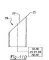
図10を参照すると、照明素子240が備わり、LED242、ファスナーおよび/またはエポキシによってLED242に取り付けられるファイバー244、ブラックジャケット・ファイバー246、およびカプラー248を含む。カプラー248はファイバー244、ブラックジャケット・ファイバー246、および蛍光性ファイバー152と結合する。蛍光性ファイバー152の直径はブラックジャケット・ファイバー246の直径と同じであっても良い。Referring to FIG. 10, thelighting element 240 is provided and includes anLED 242, afiber 244 attached to theLED 242 by a fastener and / or epoxy, ablack jacket fiber 246, and acoupler 248.Coupler 248 couples tofiber 244,black jacket fiber 246, andfluorescent fiber 152. The diameter of thefluorescent fiber 152 may be the same as the diameter of theblack jacket fiber 246.

LED242はファイバー244へ光を供給し、一般にカプラー248内にある蛍光性ファイバー152およびブラックジャケット・ファイバー246の連結部の方へ、ファイバー244によって導かれる。蛍光性ファイバー152は、ファイバー244によりLED242から光を受け、ブラックジャケット・ファイバー246へ光を導く傾斜面250を持つ端部を含む。ブラックジャケット・ファイバー246は、光路252および真っ暗な壁254を含む。蛍光性ファイバー152の傾斜面250から受けられる光は、ブラックジャケット・ファイバー246の光路252を通って導かれ、ブラックジャケット・ファイバー246の真っ暗な壁254によっての光路252内に含まれる。TheLED 242 provides light to thefiber 244 and is directed by thefiber 244 toward the junction of thefluorescent fiber 152 and the blackjacketed fiber 246, typically in thecoupler 248. Thefluorescent fiber 152 includes an end having aninclined surface 250 that receives light from theLED 242 through thefiber 244 and directs the light to the blackjacketed fiber 246.Black jacket fiber 246 includes anoptical path 252 and adark wall 254. Light received from theinclined surface 250 of thefluorescent fiber 152 is guided through theoptical path 252 of theblack jacket fiber 246 and is contained in theoptical path 252 by thedark wall 254 of theblack jacket fiber 246.

傾斜面250は、ファイバー244を経てLED242からブラックジャケット・ファイバー246へ光を反射するか、或いは蛍光性ファイバー152からブラックジャケット・ファイバー246へ光を導く。その結果、LED242からの光が蛍光性ファイバー152からの光より大きければ、LED242からの光はブラックジャケット・ファイバー246の光路252を通って伝達される。しかし、蛍光性ファイバー152がレチクルパターン22を照らすことができるくらい十分な周辺光が存在するなら、蛍光性ファイバー152はブラックジャケット・ファイバー246の光路252を通って光を導く。ブラックジャケット・ファイバー246の真っ暗な壁254のおかげで、光は、一般にブラックジャケット・ファイバー246内に含まれ、レチクルパターン22を照らすためにレチクルパターン22へ導かれる。トリチウムランプ164は蛍光性ファイバー152に取り付けられても良く、LED242および/または蛍光性ファイバー152と連動して使用されても良いし、或いは代替的に、光路252を照らすためにLED242および蛍光性ファイバー152と独立して使われても良い。Theinclined surface 250 reflects light from theLED 242 to theblack jacket fiber 246 via thefiber 244 or directs light from thefluorescent fiber 152 to theblack jacket fiber 246. As a result, if the light from theLED 242 is greater than the light from thefluorescent fiber 152, the light from theLED 242 is transmitted through theoptical path 252 of theblack jacket fiber 246. However, if there is enough ambient light to allow thefluorescent fiber 152 to illuminate thereticle pattern 22, thefluorescent fiber 152 will guide the light through theoptical path 252 of the blackjacketed fiber 246. Thanks to thedark wall 254 of theblack jacket fiber 246, light is generally contained within theblack jacket fiber 246 and directed to thereticle pattern 22 to illuminate thereticle pattern 22. Thetritium lamp 164 may be attached to thefluorescent fiber 152 and may be used in conjunction with theLED 242 and / or thefluorescent fiber 152, or alternatively, theLED 242 and the fluorescent fiber to illuminate thelight path 252. It may be used independently of 152.

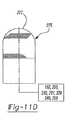
特に11Aを参照すると、照明素子256が備わり、LED258、クリアファイバー260、光路263を含むブラックジャケット・ファイバー262、およびカプラー264を含む。LED258は、ファスナーおよび/またはエポキシによってクリアファイバー260に取り付けられ、クリアファイバー260に光を提供する。クリアファイバー260および蛍光性ファイバー152からの出力は、レチクルパターン22を照らすためにブラックジャケット・ファイバー262へ導かれる。Referring specifically to 11A, theillumination element 256 is provided and includes anLED 258, aclear fiber 260, ablack jacket fiber 262 including anoptical path 263, and acoupler 264. TheLED 258 is attached to theclear fiber 260 by a fastener and / or epoxy and provides light to theclear fiber 260. The output from theclear fiber 260 and thefluorescent fiber 152 is directed to theblack jacket fiber 262 to illuminate thereticle pattern 22.

カプラー264は、機械加工または成型された2つのオフセット穴を含む。これらのオフセット穴は、3つのファイバー(クリアファイバー260、蛍光性ファイバー152およびブラックジャケット・ファイバー262)を配置する。光路263を通って伝わる光の約50%がクリアファイバー260から来て、残りは蛍光性ファイバー152から来る。蛍光性ファイバー152はクリアファイバー260より大きな直径を含み、それによって、蛍光性ファイバー152が周辺光を吸収しレチクルパターン22をもっと明るくすることができる。クリアファイバー260、カプラー264および蛍光性ファイバー152の直径の例外として、照明素子256は照明素子210(図8)に類似する。その結果、照明素子256の操作の詳細な記載は前述の通りである。Coupler 264 includes two offset holes that are machined or molded. These offset holes place three fibers (clear fiber 260,fluorescent fiber 152 and black jacket fiber 262). About 50% of the light traveling through theoptical path 263 comes from theclear fiber 260 and the rest comes from thefluorescent fiber 152. Thefluorescent fiber 152 includes a larger diameter than theclear fiber 260 so that thefluorescent fiber 152 can absorb ambient light and make thereticle pattern 22 brighter. With the exception ofclear fiber 260,coupler 264, andfluorescent fiber 152 diameter,lighting element 256 is similar to lighting element 210 (FIG. 8). As a result, the detailed description of the operation of thelighting element 256 is as described above.

上述したように、種々の照明素子200,210,211,224,240,256は、周辺条件に関係なく、レチクルパターン22を照らすのに十分な光量でレチクルパターン22に供給するために使用されても良い。前述の照明素子200、210、211、224、240、256の各々において、LED202、212、226、242、258からの光または蛍光性ファイバー152からの光は、レチクルパターン22を照らすために、レチクルパターン22に導かれる。各素子200、210、211、224、240、256において、光路206,220,221,238,252,263によって、光は光源からレチクルパターン22へ伝わる。ファイバー204,216,217,232,246,262は、光源からレチクルパターン22へ的確に光を伝える任意の適切なファイバーであっても良い。それぞれの照明素子200または211,210,211,224,240,256のファイバー204,216,217,232,246,262は、レチクルパターン22に対して配置される。光源からの光は、一般にレチクルパターン22の中心に向かって、光路206,220,221,238,252,263から導かれる。照明素子200,210,211,224,240,256からの光は、レチクルパターン22の中心照準点274(図20,23,34,36、および40)を照らすのに一般に十分であるが、全体のレチクルパターン22またはレチクルパターン22の少なくとも一部を強めて照らすために、レチクルパターン22に隣接して第2の光源が配置されても良い。As described above, thevarious lighting elements 200, 210, 211, 224, 240, and 256 are used to supply thereticle pattern 22 with a sufficient amount of light to illuminate thereticle pattern 22 regardless of the ambient conditions. Also good. In each of theaforementioned illumination elements 200, 210, 211, 224, 240, 256, the light from theLEDs 202, 212, 226, 242, 258 or the light from thefluorescent fiber 152 is used to illuminate thereticle pattern 22. Guided topattern 22. In eachelement 200, 210, 211, 224, 240, 256, light is transmitted from the light source to thereticle pattern 22 by theoptical paths 206, 220, 221, 238, 252, 263. Thefibers 204, 216, 217, 232, 246, and 262 may be any suitable fibers that accurately transmit light from the light source to thereticle pattern 22. Thefibers 204, 216, 217, 232, 246, and 262 of therespective lighting elements 200 or 211, 210, 211, 224, 240, and 256 are arranged with respect to thereticle pattern 22. Light from the light source is generally guided from theoptical paths 206, 220, 221, 238, 252, and 263 toward the center of thereticle pattern 22. The light from theillumination elements 200, 210, 211, 224, 240, 256 is generally sufficient to illuminate the central aiming point 274 (FIGS. 20, 23, 34, 36, and 40) of thereticle pattern 22, but the entire In order to intensify and illuminate at least a part of thereticle pattern 22 or thereticle pattern 22, a second light source may be disposed adjacent to thereticle pattern 22.

図11B−11Eを参照すると、中心照準点274がプリズム88に刻まれない場合、蛍光性ファイバー152および種々の照明素子200,210,211,224,240,256は、中心照準点274を照らすためにファイバーポスト275に連結されても良い。たとえば、ファイバーポスト275は、その末端部277で特定の形状を持つ細長いファイバーであっても良い。ある形態において、ファイバーポスト275の末端部277は、中心照準点274を作るために特定の照明素子200,210,211,224,240,256から受けられる光が傾斜面279(すなわち、「D」形状、図11Cおよび11E)を照らすように、傾斜面279を含む。別の形態において、傾斜面279は1対の傾斜面を含んでも良い。どちらの形態においても、ファイバーポスト275は共同出願US特許5,924,234に開示されたタイプであっても良く、その開示は参照することにより本明細書に含まれる。Referring to FIGS. 11B-11E, if the central aimingpoint 274 is not engraved on theprism 88, thefluorescent fiber 152 and thevarious illumination elements 200, 210, 211, 224, 240, 256 illuminate the central aimingpoint 274. It may be connected to thefiber post 275. For example, thefiber post 275 may be an elongated fiber having a specific shape at itsend 277. In one form, thedistal end 277 of thefiber post 275 allows the light received from aparticular illumination element 200, 210, 211, 224, 240, 256 to create a central aimingpoint 274 on the inclined surface 279 (ie, “D”). Aninclined surface 279 is included to illuminate the shape, FIGS. 11C and 11E). In another form, theinclined surface 279 may include a pair of inclined surfaces. In either form,fiber post 275 may be of the type disclosed in joint application US Pat. No. 5,924,234, the disclosure of which is hereby incorporated by reference.

蛍光性ファイバー152がファイバーポスト275に連結される場合、ファイバー152は照明末端部277からファイバーポスト275の対向端部で取り付けられても良い。照明素子200,210,211,224,240,256の1つは、ファイバーポスト275に取り付けられる場合、それぞれの照明素子200,210,211,224,240,256のファイバー204,216,217,232,246,262は、照明末端部277からファイバーポスト275の対向端部で同様に取り付けられても良い。If thefluorescent fiber 152 is coupled to thefiber post 275, thefiber 152 may be attached from theillumination end 277 to the opposite end of thefiber post 275. When one of thelighting elements 200, 210, 211, 224, 240, 256 is attached to thefiber post 275, thefibers 204, 216, 217, 232 of therespective lighting elements 200, 210, 211, 224, 240, 256 are used. , 246, 262 may be similarly attached at the opposite end of thefiber post 275 from theillumination end 277.

特に図12〜39を参照すると、エレクトロルミネッセント素子(すなわち、LED、エレクトロルミネッセント・フィルムなど)を含む一連の照明素子が、レチクルパターン22を照らすために、照明素子200,210,211,224,240,256のファイバー204,216,217,232,246,262からの出力と連動して使用するために提供される。図12〜39の照明素子は、照明素子200,210,211,224,240,256のファイバー204,216,217,232,246,262のいずれかと連動して使われても良いが、図12〜39の照明素子は、便宜のために照明素子200のファイバー204と関連するように、以下に記載され図に示される。With particular reference to FIGS. 12-39, a series of illumination elements, including electroluminescent elements (ie, LEDs, electroluminescent films, etc.), illuminate thereticle pattern 22 to illuminate thereticle pattern 22. , 224, 240, 256fibers 204, 216, 217, 232, 246, 262 provided for use in conjunction with the output. 12 to 39 may be used in conjunction with any one of thefibers 204, 216, 217, 232, 246, and 262 of thelighting elements 200, 210, 211, 224, 240, and 256, but FIG. ~ 39 lighting elements are described below and shown in the figures as associated with thefiber 204 of thelighting element 200 for convenience.

図12および13を参照すると、照明素子206が備わりLED268および光学素子270を含む。LED268は光学素子270およびミラープリズム88の両方または1つに取り付けられ、光学素子270に光を供給する。光学素子270は光学プラスチック素子であっても良いし、LED268からミラープリズム88の方へ光を均等に分散する分散面であっても良い。Referring to FIGS. 12 and 13, alighting element 206 is provided and includes anLED 268 and anoptical element 270. TheLED 268 is attached to both or one of theoptical element 270 and themirror prism 88 and supplies light to theoptical element 270. Theoptical element 270 may be an optical plastic element or a dispersion surface that uniformly disperses light from theLED 268 toward themirror prism 88.

LED268および光学素子270の間で協働することにより、ミラープリズム88は、充分な光を与えられ、ミラープリズム88の十分以上の面積を与えられる。スタジア線272を含むレチクルパターン22を十分に照らすために(図20、23,34,36および40)、照明素子200からのファイバー204はミラープリズム88の中心照準点274の上に中心が置かれる。その結果、ファイバー204からの光が一般に中心照準点274へ導かれ、スタジア線272を含むレチクルパターン22全体を十分に照らさない。光学素子270は実質的にレチクルパターン22全体をカバーする形状を含むので、LED268からの光は、光学素子270中に散乱され、レチクルパターン22全体を十分に照らし、レチクルパターン22の中心照準点274およびスタジア線272の両方を含む。By cooperating between theLED 268 and theoptical element 270, themirror prism 88 is provided with sufficient light and is provided with a sufficient area of themirror prism 88. In order to fully illuminate thereticle pattern 22 including the stadia line 272 (FIGS. 20, 23, 34, 36 and 40), thefiber 204 from theillumination element 200 is centered on thecenter aiming point 274 of themirror prism 88. . As a result, light from thefiber 204 is generally directed to the central aimingpoint 274 and does not fully illuminate theentire reticle pattern 22 including thestadia line 272. Since theoptical element 270 includes a shape that substantially covers theentire reticle pattern 22, the light from theLED 268 is scattered into theoptical element 270, sufficiently illuminating theentire reticle pattern 22, and a central aimingpoint 274 of thereticle pattern 22. And stadia line 272.

図14を参照すると、照明素子276が備わり、LED278、光学素子280、およびファイバー282を含む。LED278は光学素子280およびミラープリズム88の1つに取り付けられ、光学素子280に光を供給する。スタジア線272および中心照準点274を含むレチクルパターン22を完全に照らすために、光学素子280は、LED278から放射される光をミラープリズム88へ等しく分散する分散面279を含んでも良い。LED278からの迷光がファイバー282によって捕捉され、一般にミラープリズム88およびレチクルパターン22の方へ導かれるように、ファイバー282はLED278に取り付けられても良い。ファイバー282の出力は、中心照準点274をさらに照らすために、一般に中心照準点274上に配置されても良いし、照明素子200のファイバー204からの光と組み合わされても良い。Referring to FIG. 14, alighting element 276 is provided and includes anLED 278, anoptical element 280, and afiber 282. TheLED 278 is attached to one of theoptical element 280 and themirror prism 88 and supplies light to theoptical element 280. In order to fully illuminate thereticle pattern 22 including thestadia line 272 and the central aimingpoint 274, theoptical element 280 may include adispersion surface 279 that equally distributes the light emitted from theLED 278 to themirror prism 88. Thefiber 282 may be attached to theLED 278 so that stray light from theLED 278 is captured by thefiber 282 and generally directed toward themirror prism 88 and thereticle pattern 22. The output of thefiber 282 may generally be placed on the central aimingpoint 274 to further illuminate the central aimingpoint 274 or may be combined with the light from thefiber 204 of theillumination element 200.

図15を参照すると、照明素子284が備わり、LED286および光学素子288を含む。LED286が光学素子288へ導かれ光学素子288によって受けられるように、LED286は光学素子288と離間している。光学素子288はミラープリズム88に取り付けられ、全レチクルパターン22にわたってLED286からの放射光の焦点分布を増大する平凹レンズを含んでも良い。照明素子266、276に関して上述したように、レチクルパターン22全体を照らすことにより、スタジア線272および中心照準点274を照らすこともできる。中心照準点274は照明素子200のファイバー204によってさらに照らされても良い。Referring to FIG. 15, alighting element 284 is provided and includes anLED 286 and anoptical element 288. TheLED 286 is spaced apart from theoptical element 288 so that theLED 286 is directed to and received by theoptical element 288. Theoptical element 288 is attached to themirror prism 88 and may include a plano-concave lens that increases the focal distribution of the emitted light from theLED 286 over theentire reticle pattern 22. As described above with respect to theillumination elements 266, 276, thestadia line 272 and the central aimingpoint 274 can also be illuminated by illuminating theentire reticle pattern 22. The central aimingpoint 274 may be further illuminated by thefiber 204 of theillumination element 200.

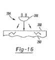
光学素子288は平凹レンズであるとして記載されているが、光学素子288は、光散乱分散面290を持つ平凹レンズを代替的に含む(図16)。スタジア線272および中心照準点274を十分に照らすために、分散面290はLED286から光を受け、レチクルパターン22全体にわたって光を散乱する。図15の照明素子284と同様に、光学素子288は、分散面290を含み、照明素子200のファイバー204と連動して使用されても良い。Althoughoptical element 288 is described as being a plano-concave lens,optical element 288 alternatively includes a plano-concave lens having a light scattering dispersion surface 290 (FIG. 16). In order to sufficiently illuminate thestadia line 272 and the central aimingpoint 274, thedispersion surface 290 receives light from theLED 286 and scatters light across thereticle pattern 22. Similar to theillumination element 284 of FIG. 15, theoptical element 288 includes adispersion surface 290 and may be used in conjunction with thefiber 204 of theillumination element 200.

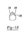
図17および18を参照すると、照明素子292が備わり、LED294およびレンズ296を含む。LED294からの光がレンズ296によって受けられように、LED294はレンズ296に取り付けられても良い。レンズ296はミラープリズム88に取り付けられても良く、レンズ296を通ってLED294から一般にミラープリズム88に形成されたレチクルパターン22へ光を導く1対の傾斜面298を含む。Referring to FIGS. 17 and 18, alighting element 292 is provided and includes anLED 294 and alens 296. TheLED 294 may be attached to thelens 296 so that light from theLED 294 is received by thelens 296. Thelens 296 may be attached to themirror prism 88 and includes a pair ofinclined surfaces 298 that guide light through thelens 296 from theLED 294 to thereticle pattern 22 generally formed in themirror prism 88.

照明素子292は、中心照準点274を直接に照らすために、照明素子200のファイバー204または223は一般にレンズ296を通って受けられるように、照明素子200と連動して使われても良い。スタジア線272および中心照準点274を含むレチクルパターン22を十分に照らすために、LED294からの光は照明素子200のファイバー204と連動して使われても良い。Theillumination element 292 may be used in conjunction with theillumination element 200 so that thefiber 204 or 223 of theillumination element 200 is generally received through thelens 296 to directly illuminate the central aimingpoint 274. Light from theLED 294 may be used in conjunction with thefiber 204 of theillumination element 200 to sufficiently illuminate thereticle pattern 22 including thestadia line 272 and the central aimingpoint 274.

図19を参照すると、照明素子306が備わり、LED308および光学素子310を含む。LED308は光学素子310から離間し、光学素子310に光を供給する。光学素子310はミラープリズム88に取り付けられ、レチクルパターン22全体にわたってLED308からの放射光の焦点分布を増大させる凸レンズであっても良い。照明素子266に関して上述したように、レチクルパターン22全体にわたって光を導くことによって、レチクルパターン22のスタジア線272および中心照準点274を照らす。中心照準点274は照明素子200のファイバー204によってさらに照らされても良い。Referring to FIG. 19, an illumination element 306 is provided and includes anLED 308 and anoptical element 310. TheLED 308 is separated from theoptical element 310 and supplies light to theoptical element 310. Theoptical element 310 may be a convex lens that is attached to themirror prism 88 and increases the focal distribution of the emitted light from theLED 308 over theentire reticle pattern 22. As described above with respect to theillumination element 266, thestadia line 272 and the central aimingpoint 274 of thereticle pattern 22 are illuminated by directing light across thereticle pattern 22. The central aimingpoint 274 may be further illuminated by thefiber 204 of theillumination element 200.

図20および21を参照すると、照明素子312が備わり、LED314および光学素子316を含む。LED314は光学素子316および/またはミラープリズム88に取り付けられても良い。スタジア線272および中心照準点274を含むレチクルパターン22を照らすために、LED314は光学素子316に光を供給する。Referring to FIGS. 20 and 21, anillumination element 312 is provided and includes anLED 314 and anoptical element 316. TheLED 314 may be attached to theoptical element 316 and / or themirror prism 88.LED 314 provides light tooptical element 316 to illuminatereticle pattern 22 including stadia line 272 and central aimingpoint 274.

光学素子316は、レチクルパターン22全体にわたってLED314から放射される光を分散するガラスディフューザーであっても良い。光学素子316の外表面は、内部反射を補助するために反射コーティングを塗られても良い。照明素子200が中心照準点274をさらに照らすことができるように、照明素子312は照明素子200と連動して使用されても良い。Theoptical element 316 may be a glass diffuser that disperses the light emitted from theLED 314 throughout thereticle pattern 22. The outer surface of theoptical element 316 may be coated with a reflective coating to assist in internal reflection. Theillumination element 312 may be used in conjunction with theillumination element 200 so that theillumination element 200 can further illuminate the central aimingpoint 274.

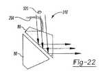
図22を参照すると、LED320からの光がスタジア線272および中心照準点274を含むレチクルパターン22を十分に照らすことができるように、照明素子318が備わり、所定の距離だけミラープリズム88と離間したLED320を含む。照明素子200のファイバー204が中心照準点274へ導かれ、中心照準点274をさらに照らすために、照明素子318は照明素子200と連動して使用されても良い。Referring to FIG. 22, anillumination element 318 is provided so that light from theLED 320 can sufficiently illuminate thereticle pattern 22 including thestadia line 272 and the central aimingpoint 274, and is separated from themirror prism 88 by a predetermined distance.LED 320 is included. Theillumination element 318 may be used in conjunction with theillumination element 200 to guide thefiber 204 of theillumination element 200 to the central aimingpoint 274 and further illuminate the central aimingpoint 274.

図23および24を参照すると、照明素子322が備わり、LED324および光学素子326を含む。LED324は、光学素子326および/またはミラープリズム88に取り付けられても良いし、レチクルパターン22を照らすために光学素子326に光を提供する。光学素子326は、LED324からレチクルパターン22へ放射される光を分散する鏡面仕上げの上面327を持つガラスディフューザーであっても良い。光学素子326の外表面は、光学素子326の内部反射を補助するために反射コーティングを塗られても良い。照明素子200のファイバー204が中心照準点274さらに照らすことができるように、照明素子322は照明素子200と連動して使用されても良い。Referring to FIGS. 23 and 24, anillumination element 322 is provided and includes anLED 324 and anoptical element 326. TheLED 324 may be attached to theoptical element 326 and / or themirror prism 88 and provides light to theoptical element 326 to illuminate thereticle pattern 22. Theoptical element 326 may be a glass diffuser having a mirror-finishedupper surface 327 that disperses light emitted from theLED 324 to thereticle pattern 22. The outer surface of theoptical element 326 may be coated with a reflective coating to assist internal reflection of theoptical element 326. Theillumination element 322 may be used in conjunction with theillumination element 200 so that thefiber 204 of theillumination element 200 can further illuminate the central aimingpoint 274.

図25を参照すると、照明素子328が備わり、LED330および反射器332を含む。LED330は反射器332から離間し、レチクルパターン22を照らすために反射器332に光を供給する。レチクルパターン22を照らすためにLED330から一般にミラープリズム88へ受けられる光を導くために、反射器332は凹面形状を含んでも良い。照明素子200のファイバー204が中心照準点274を照らすことができるように、照明素子328は照明素子200と連動して使用されても良い。Referring to FIG. 25, alighting element 328 is provided and includes anLED 330 and areflector 332. TheLED 330 is spaced from thereflector 332 and supplies light to thereflector 332 to illuminate thereticle pattern 22. In order to direct light that is typically received from theLED 330 to themirror prism 88 to illuminate thereticle pattern 22, thereflector 332 may include a concave shape. Theillumination element 328 may be used in conjunction with theillumination element 200 so that thefiber 204 of theillumination element 200 can illuminate the central aimingpoint 274.

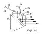
図26を参照すると、照明素子334が備わり、LED336、ファイバー338および光学素子340を含む。LED336はファイバー338に取り付けられ、それはLED336から一般に光学素子340へ導く。光学素子340は、ファイバー338によりLED336から光を受け、スタジア線272および中心照準点274を照らすために、一般にレチクルパターン22へ光を導く。レチクルパターン22の全体にわたってLED336から光を均等に分配するために粗面341であると同様に、光学素子340はガラスまたはプラスチックから形成されても良いし、任意の形状を含んでも良い。照明素子200のファイバー204が中心照準点274を照らすことができるように、照明素子334は照明素子200と連動して使用されても良い。Referring to FIG. 26, anillumination element 334 is provided and includes anLED 336, afiber 338 and anoptical element 340. TheLED 336 is attached to thefiber 338, which leads from theLED 336 generally to theoptical element 340.Optical element 340 receives light fromLED 336 throughfiber 338 and directs light generally toreticle pattern 22 to illuminatestadia line 272 and central aimingpoint 274. Similar to the roughenedsurface 341 for evenly distributing light from theLEDs 336 throughout thereticle pattern 22, theoptical element 340 may be formed from glass or plastic, and may include any shape. Theillumination element 334 may be used in conjunction with theillumination element 200 so that thefiber 204 of theillumination element 200 can illuminate the central aimingpoint 274.

図27を参照すると、照明素子342が備わり、LED344および直角プリズム346を含む。直角プリズム346はミラープリズム88に取り付けられても良いが、LED344は直角プリズム346に取り付けられても良い。直角プリズム346がレチクルパターン22の全領域にわたって光を導くことができるように、LED344は直角プリズム346に光を供給する。LED344からの直角プリズム346によって受けられる光のほとんどがレチクルパターン22へ導かれるということを保証するために、直角プリズム346の4側面は、直角プリズム346の内部反射率を増大するためのミラーコーティングを含む。Referring to FIG. 27, anillumination element 342 is provided and includes anLED 344 and a right-angle prism 346. The right-angle prism 346 may be attached to themirror prism 88, but theLED 344 may be attached to the right-angle prism 346. TheLED 344 provides light to the right-angle prism 346 so that the right-angle prism 346 can direct light over the entire area of thereticle pattern 22. In order to ensure that most of the light received by theright angle prism 346 from theLED 344 is directed to thereticle pattern 22, the four sides of theright angle prism 346 have a mirror coating to increase the internal reflectivity of theright angle prism 346. Including.

直角プリズム346は、LED344からの光が直角プリズム346に入ることができるマスクを含んでも良い。直角プリズム346からの光は、スタジア線272および中心照準点274を含むレチクルパターン22の十分な照明が可能なミラープリズム88によって受けられる。照明素子200のファイバー204が中心照準点274を照らすことができるように、照明素子342は照明素子200と連動して使用されても良い。Right angle prism 346 may include a mask that allows light fromLED 344 to enterright angle prism 346. Light from theright angle prism 346 is received by amirror prism 88 capable of sufficient illumination of thereticle pattern 22 including thestadia line 272 and the central aimingpoint 274. Theillumination element 342 may be used in conjunction with theillumination element 200 so that thefiber 204 of theillumination element 200 can illuminate the central aimingpoint 274.

図28を参照すると、照明素子348が備わり、LED350および光学素子352を含む。レチクルパターン22を照らすときに光学素子352によって使用するために、LED350は、ハーフボールレンズ352および/またはミラープリズム88に取り付けられ、ハーフボールレンズ352へ光を提供する。光学素子352は、LED350から放射される光を等しく分散するハーフボールレンズ352であっても良いし、ハーフボールレンズ352の内部反射を補助する反射コーティングを塗布された外表面を含んでも良い。スタジア線272および中心照準点274を含むレチクルパターン22を十分に照らすために、ハーフボールレンズ352は、光がLED350から受けられるくらい十分なサイズを含む。照明素子200のファイバー204がさらに中心照準点274を照らすことができるように、照明素子348は照明素子200と連動して使われても良い。Referring to FIG. 28, anillumination element 348 is provided and includes anLED 350 and anoptical element 352. TheLED 350 is attached to thehalf ball lens 352 and / or themirror prism 88 and provides light to thehalf ball lens 352 for use by theoptical element 352 when illuminating thereticle pattern 22. Theoptical element 352 may be ahalf ball lens 352 that equally disperses the light emitted from theLED 350, or may include an outer surface coated with a reflective coating that assists in internal reflection of thehalf ball lens 352. In order to fully illuminate thereticle pattern 22 including thestadia line 272 and the central aimingpoint 274, thehalf ball lens 352 includes a size sufficient to allow light to be received from theLED 350. Theillumination element 348 may be used in conjunction with theillumination element 200 so that thefiber 204 of theillumination element 200 can further illuminate the central aimingpoint 274.

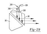
図29を参照すると、照明素子354が備わり、LED356および直角プリズム358を含む。レチクルパターン22を照らすときに直角プリズム358によって使用するために、LED356は、直角プリズム358に取り付けられても良く、直角プリズム358に光を提供する。直角プリズム358はミラープリズム88に取り付けられても良い。直角プリズム358の4つの側面は、LED356からの光がレチクルパターン22へ導かれることを保証するために直角プリズム358の内部反射率を増加するためにミラーコーティングを含んでも良い。LED356と接触して直角プリズム358の側面は、LED356からの光が直角プリズム358に入ることができるようにマスクを含んでも良い。照明素子200のファイバー204が中心照準点274を照らすことができるように、照明素子354は照明素子200と連動して使われても良い。Referring to FIG. 29, anillumination element 354 is provided and includes anLED 356 and a right-angle prism 358. TheLED 356 may be attached to the right-angle prism 358 and provides light to the right-angle prism 358 for use by the right-angle prism 358 when illuminating thereticle pattern 22. The right-angle prism 358 may be attached to themirror prism 88. The four sides of theright angle prism 358 may include a mirror coating to increase the internal reflectivity of theright angle prism 358 to ensure that light from theLED 356 is directed to thereticle pattern 22. The sides of theright angle prism 358 in contact with theLED 356 may include a mask so that light from theLED 356 can enter theright angle prism 358. Theillumination element 354 may be used in conjunction with theillumination element 200 so that thefiber 204 of theillumination element 200 can illuminate the central aimingpoint 274.

図30を参照すると、照明素子360が備わり、LED362およびハーフボールレンズ364を含む。レチクルパターン22を照らすために、LED362は、ハーフボールレンズ364に取り付けられても良いし、ハーフボールレンズ364に光を供給しても良い。LED362からレチクルパターン22へ光を導くために、ハーフボールレンズ364はミラープリズム88に取り付けられても良い。ハーフボールレンズの外表面は、内部反射率を補助するために反射コーティングを塗られても良い。照明素子200のファイバー204が中心照準点274を照らすように、照明素子360は照明素子200と連動して使われても良い。Referring to FIG. 30, anillumination element 360 is provided and includes anLED 362 and ahalf ball lens 364. In order to illuminate thereticle pattern 22, theLED 362 may be attached to thehalf ball lens 364 or may supply light to thehalf ball lens 364. In order to guide light from theLED 362 to thereticle pattern 22, thehalf ball lens 364 may be attached to themirror prism 88. The outer surface of the half ball lens may be coated with a reflective coating to assist in internal reflectivity. Theillumination element 360 may be used in conjunction with theillumination element 200 so that thefiber 204 of theillumination element 200 illuminates the central aimingpoint 274.

図31を参照すると、照明素子366が備わり、LED368および光学素子370を含む。LED368は、ミラープリズム88から一般に光学素子370へ導かれる光を有するミラープリズム88に実装された面であっても良い。光学素子370は、レチクルパターン22を等しく照らすために、光線経路を分配し広げる放物面鏡、球面鏡、或いは凹球面鏡であっても良い。照明素子200のファイバー204は中心照準点274を照らすことができるように、照明素子366は照明素子200と連動して使われても良い。Referring to FIG. 31, anillumination element 366 is provided and includes anLED 368 and anoptical element 370. TheLED 368 may be a surface mounted on themirror prism 88 having light generally guided from themirror prism 88 to theoptical element 370. Theoptical element 370 may be a parabolic mirror, a spherical mirror, or a concave spherical mirror that distributes and broadens the light path to illuminate thereticle pattern 22 equally. Theillumination element 366 may be used in conjunction with theillumination element 200 so that thefiber 204 of theillumination element 200 can illuminate the central aimingpoint 274.

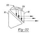
図32を参照すると、照明素子372が備わり、広視野角を持つLED374を使うことにより、LED374はレチクルパターン22を十分に照らすことができる。照明素子200のファイバー204が中心照準点274を照らすことができるように、照明素子372は照明素子200と連動して使われても良い。Referring to FIG. 32, theLED 374 can sufficiently illuminate thereticle pattern 22 by using theLED 374 having theillumination element 372 and having a wide viewing angle. Theillumination element 372 may be used in conjunction with theillumination element 200 so that thefiber 204 of theillumination element 200 can illuminate the central aimingpoint 274.

図33を参照すると、照明素子376が備わり、クリアレンズ380に実装されたLED378を含む。レンズ380はミラープリズム88に実装されても良いし、LED378から一般にミラープリズム88に導いても良い。ミラープリズム88へ光を導くことにより、LED378およびレンズ380は、スタジア線272および中心照準点274を含むレチクルパターン22を十分に照らすことができる。照明素子200のファイバー204が中心照準点274を照らすことができるように、照明素子376は照明素子200と連動して使われても良い。Referring to FIG. 33, anillumination element 376 is provided and includes anLED 378 mounted on aclear lens 380. Thelens 380 may be mounted on themirror prism 88 or may be led from theLED 378 to themirror prism 88 in general. By directing light to themirror prism 88, theLED 378 and thelens 380 can sufficiently illuminate thereticle pattern 22 including thestadia line 272 and the central aimingpoint 274. Theillumination element 376 may be used in conjunction with theillumination element 200 so that thefiber 204 of theillumination element 200 can illuminate the central aimingpoint 274.

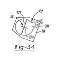
図34を参照すると、照明素子382が備わり、ミラープリズム88も実装される光学素子384を含む。光学素子384は、ミラープリズム88の面に光学接着剤で接着された、円形チップカットしたエレクトロルミネッセント・フラットフィルム・ランプであっても良い。光学素子384は、レチクルパターン22にわたって種々の色で等しく光を分散する。照明素子200のファイバー204が中心照準点274を照らすことができるように、照明素子382は照明素子200と連動して使われても良い。Referring to FIG. 34, anillumination element 382 is provided and includes anoptical element 384 on which amirror prism 88 is also mounted. Theoptical element 384 may be a circular chip-cut electroluminescent flat film lamp bonded to the surface of themirror prism 88 with an optical adhesive.Optical element 384 distributes light equally in various colors acrossreticle pattern 22. Theillumination element 382 may be used in conjunction with theillumination element 200 so that thefiber 204 of theillumination element 200 can illuminate the central aimingpoint 274.

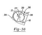
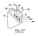
図36および37を参照すると、照明素子386が備わり、エレクトロルミネッセント・ワイヤランプ388および光学素子390を含む。エレクトロルミネッセント・ワイヤランプ388からレチクルパターン22へ光を導くために、光学素子390は、ミラープリズム88に取り付けられるガラスディフューザーであっても良いし、エレクトロルミネッセント・ワイヤランプ388から光を受けても良い。ガラスディフューザーは、エレクトロルミネッセント・ワイヤランプ388から放射された光を等しく分散する鏡面仕上げの上面389を含み、光学素子390の内部反射率を補助するために反射コーティングを塗られた外表面を含んでも良い。照明素子200のファイバー204が中心照準点274を直接に照らすことができるように、照明素子386は照明素子200と連動して使われても良い。36 and 37, anillumination element 386 is provided and includes anelectroluminescent wire lamp 388 and anoptical element 390. In order to direct light from theelectroluminescent wire lamp 388 to thereticle pattern 22, theoptical element 390 may be a glass diffuser attached to themirror prism 88, or light from theelectroluminescent wire lamp 388. You may receive it. The glass diffuser includes a mirror-finishedtop surface 389 that evenly disperses the light emitted from theelectroluminescent wire lamp 388 and has an outer surface coated with a reflective coating to assist the internal reflectivity of theoptical element 390. May be included. Theillumination element 386 may be used in conjunction with theillumination element 200 so that thefiber 204 of theillumination element 200 can directly illuminate the central aimingpoint 274.

図38および39を参照すると、照明素子392が備わり、ミラープリズム88に実装された鋳造アルミニウム円形ブロック394を含む。機械加工/鋳造ブロック394は窪み395を持ち、それは研磨されるか、或いは反射コーティングを塗られる。LED398は機械加工/鋳造ブロック394の側面でドリル穴に挿入される。LED398からの光は、光路397を通って機械加工/鋳造ブロック394の窪み395へ導かれ、機械加工/鋳造ブロック394の磨き面または塗布面から反射され、スタジア線272を照らすために一般にレチクルパターン22へ導かれる。照明素子392は、LED398およびファイバー204から一般にレチクルパターン22へ放射された光を分散するときに補助するために、窪み395内に配置された紫外線接着剤401をさらに含んでも良い。38 and 39, theillumination element 392 is provided and includes a castaluminum circular block 394 mounted on themirror prism 88. The machining /casting block 394 has arecess 395 that is polished or coated with a reflective coating. TheLED 398 is inserted into the drill hole at the side of the machining /casting block 394. Light from theLED 398 is directed through theoptical path 397 to therecess 395 of the machining /casting block 394, reflected from the polished or coated surface of the machining /casting block 394, and generally a reticle pattern to illuminate thestadia line 272. To 22. Thelighting element 392 may further include a UV adhesive 401 disposed in therecess 395 to assist in dispersing light emitted from theLED 398 andfiber 204 generally into thereticle pattern 22.

照明素子200のファイバー204が中心照準点274を照らすことができるように、照明素子392は照明素子200と連動して使われても良い。照明素子392が照明素子200と連動して使われる場合は、ジャケットファイバー204の一端部は、クリアファイバー396を暴露するために取り除かれても良い。照明素子200のファイバー204から中心照準点274へ光を照らすために、クリアファイバー396はアルミニウム円形モールド394を通して伸びても良い。紫外線接着剤401に拡散されたクリアファイバー396からの光を防ぐために、クリアファイバー396は不透明なコーティング或いは反射コーティングを塗られても良い。Theillumination element 392 may be used in conjunction with theillumination element 200 so that thefiber 204 of theillumination element 200 can illuminate the central aimingpoint 274. If thelighting element 392 is used in conjunction with thelighting element 200, one end of thejacket fiber 204 may be removed to expose theclear fiber 396. Theclear fiber 396 may extend through the aluminumcircular mold 394 to shine light from thefiber 204 of theillumination element 200 to the central aimingpoint 274. In order to prevent light from theclear fiber 396 diffused in theUV adhesive 401, theclear fiber 396 may be coated with an opaque coating or a reflective coating.

図6を参照すると、照明系18と共に使用するための制御系172が備わり、回転スイッチ、スリーブ、またはダイヤル174、バッテリー167のような電源、および光センサおよび/またはフォトダイオードを含む。制御系172は回転素子174と連絡しても良く、それは、ハウジング12に対して回転素子174を回転することによって使用者が照明系18の操作を制御することができる複数の場所を含んでも良い。たとえば、回転素子174は、照明素子18が蛍光性ファイバー152によって単独でレチクルパターン22へ光を供給するような位置に動かされて良い(すなわち、回転素子174は「OFF」の位置にある)。代替的に、回転素子174は、図7〜39に示される任意の形態を使ってLED162と連動して、光が蛍光性ファイバー152を経由してレチクルパターン22へ供給されるように位置合わせされても良い。光学照準器10が使用される環境条件に基づいてレチクルパターン22に供給される光量を自動的に調節するために、光センサーおよび/またはフォトダイオード178が使われ、回転素子174に位置合わせされても良い。回転素子174は、使用者がLED162、トリチウムランプ164、光センサおよび/またはフォトダイオード、およびOFF位置の間で選択することができる任意の位置で位置合わせされても良く、それによって、蛍光性ファイバー152によって供給されるものだけにレチクルパターン22へ供給される光を制限する、Referring to FIG. 6, acontrol system 172 for use with theillumination system 18 is provided and includes a rotary switch, sleeve or dial 174, a power source such as abattery 167, and a light sensor and / or photodiode. Thecontrol system 172 may communicate with therotating element 174, which may include multiple locations where the user can control the operation of theillumination system 18 by rotating therotating element 174 relative to thehousing 12. . For example, therotating element 174 may be moved to a position such that theillumination element 18 supplies light to thereticle pattern 22 by thefluorescent fiber 152 alone (ie, therotating element 174 is in the “OFF” position). Alternatively, therotating element 174 is aligned such that light is supplied to thereticle pattern 22 via thefluorescent fiber 152 in conjunction with theLED 162 using any form shown in FIGS. May be. In order to automatically adjust the amount of light supplied to thereticle pattern 22 based on the environmental conditions in which theoptical sight 10 is used, a light sensor and / orphotodiode 178 is used and aligned with therotating element 174. Also good. Therotating element 174 may be aligned at any position that the user can select between theLED 162, thetritium lamp 164, the light sensor and / or photodiode, and the OFF position, thereby allowing the fluorescent fiber Limit the light supplied to thereticle pattern 22 to only that supplied by 152.

バッテリー167はLED162および光センサーおよび/またはフォトダイオード178に電源を供給しても良い。バッテリー167を使いきったら、レチクルパターン22を照らすために蛍光性ファイバー152と連動して、トリチウムランプ164を使っても良い。バッテリー167が低ければ、使用者に低バッテリーを知らせるために、制御系172の最初のスタート時に、制御系172を所定数のパルスで点滅させても良い。Thebattery 167 may supply power to theLED 162 and the light sensor and / or thephotodiode 178. When thebattery 167 is used up, atritium lamp 164 may be used in conjunction with thefluorescent fiber 152 to illuminate thereticle pattern 22. If thebattery 167 is low, thecontrol system 172 may be blinked with a predetermined number of pulses when thecontrol system 172 is first started to inform the user of the low battery.

制御系172は、使用者が照明系18を制御できるon/offスイッチであるテープスイッチ180を含んでも良い。テープスイッチ180が「ON」位置にあるとき、制御系172がレチクルパターン22に回転素子174の位置と一致した光量を供給するように、テープスイッチ180は制御系172と連絡していても良い。たとえば、蛍光性ファイバー152と連動して、回転素子174は、LED162がレチクルパターン22に光を供給する位置にある場合、テープスイッチ180を「ON」位置に変えることによって、LED162および蛍光性ファイバー152を使ってレチクルパターン22を照らす。テープスイッチ180を「OFF」位置に押圧することによって、制御系172をシャットダウンし、レチクルパターン22へ供給される光を蛍光性ファイバー152およびトリチウムランプ164によって供給されるものだけに制限する。Thecontrol system 172 may include atape switch 180 that is an on / off switch that allows the user to control theillumination system 18. When thetape switch 180 is in the “ON” position, thetape switch 180 may communicate with thecontrol system 172 so that thecontrol system 172 supplies thereticle pattern 22 with an amount of light that matches the position of therotating element 174. For example, in conjunction with thefluorescent fiber 152, therotating element 174 is configured to change theLED switch 162 and thefluorescent fiber 152 by turning thetape switch 180 to the “ON” position when theLED 162 is in a position to supply light to thereticle pattern 22. Illuminate thereticle pattern 22 using. Pressing thetape switch 180 to the “OFF” position shuts down thecontrol system 172 and limits the light supplied to thereticle pattern 22 to only that supplied by thefluorescent fiber 152 and thetritium lamp 164.

回転素子174は、回転素子174は種々のセッティングと関連した抵抗システムおよび/またはパルス幅変調回路を含んでも良い。たとえば、回転素子174がパルス幅変調(PWM)制御を使うように位置合わせされるとき、制御系172によってLED162へ供給される信号に依存して、LED162の全照明の0%〜100%間でLED162によって供給される光量を制御するために、PWM信号はLED162へ供給される。この結果各セッティングはLED162へ供給されるPWM信号を20%までに増加させる。回転素子174を種々の位置の間で回転するとき、LED162の強度は増大し、レチクルパターン22の照明は同様に増大する。Rotating element 174 may include a resistance system and / or a pulse width modulation circuit associated with various settings. For example, when therotating element 174 is aligned to use pulse width modulation (PWM) control, depending on the signal supplied to theLED 162 by thecontrol system 172, between 0% and 100% of the total illumination of theLED 162. A PWM signal is supplied to theLED 162 to control the amount of light supplied by theLED 162. As a result, each setting increases the PWM signal supplied to theLED 162 by 20%. When therotating element 174 is rotated between various positions, the intensity of theLED 162 increases and the illumination of thereticle pattern 22 increases as well.

PWM制御の使用に加えて、回転素子174は、抵抗、ハーフ効果、レードスイッチ、または磁気スイッチシステムを含んでも良い。この結果、回転素子174がハウジング12に対して回転するとき、LED162の照明は直接に変調され、増加/減少する。そのような方法でLED162の照明を制御することにより、LED162のコントロールを何回でも行うことができ、実質的に任意の照度でその結果レチクルパターン22を照らすことができる。In addition to using PWM control, therotating element 174 may include a resistor, half-effect, rade switch, or magnetic switch system. As a result, when therotating element 174 rotates relative to thehousing 12, the illumination of theLED 162 is directly modulated and increased / decreased. By controlling the illumination of theLED 162 in such a manner, theLED 162 can be controlled any number of times, and the resultingreticle pattern 22 can be illuminated with virtually any illuminance.

図40および41を参照すると、レチクル22は表示(ディスプレイ)182と連動して示される。表示182は、制御系172と連絡していて、制御系172から指示を受けても良い。データ表示182は前述の照明素子200、210、211、224、240、256のいずれ、および/または図12〜39に示された照明素子のいずれとも連動して使われても良い。使用者がレチクル22に隣接して表示された情報を見ることができるように、制御系172は、たとえば、座標、レンジ、テキストメッセージ、および/または目標識別情報のようなデータを表示182に供給しても良い。表示182はレンジに関係した情報を提供する場合、光学照準器10はそのような情報を提供するレンジファインダー(示されていない)を含んでも良い。光学照準器10の使用に像を伝達するときに使うために、表示182はLED、7区分表示、または液晶表示(LCD)または他のデジタル接眼レンズ素子を含んでも良い。40 and 41, thereticle 22 is shown in conjunction with adisplay 182. FIG.Display 182 communicates withcontrol system 172 and may receive instructions fromcontrol system 172. The data display 182 may be used in conjunction with any of thelighting elements 200, 210, 211, 224, 240, 256 described above and / or any of the lighting elements shown in FIGS.Control system 172 provides data such as coordinates, ranges, text messages, and / or target identification information to display 182 so that a user can view the information displayed adjacent toreticle 22. You may do it. If thedisplay 182 provides range related information, theoptical sight 10 may include a range finder (not shown) that provides such information. Thedisplay 182 may include an LED, a seven-segment display, or a liquid crystal display (LCD) or other digital eyepiece element for use in transmitting an image for use with theoptical sight 10.

表示182は、プリズム88の表面からコーティングを除去することによって形成されても良い。たとえば、光が材料の除去されたプリズム88−露出領域−を通って進むことができるように、アルミニウムがプリズムの表面から取り除かれても良い。所定の色は通過することが制限されるが、殆どの周辺光がそこを通って進むことができるように、露出領域は2色性コーティングで塗られても良い。たとえば、情報が赤色でプリズム88に表示される場合、使用者は露出領域においても光学照準器10を通して見ることができるように、2色性コーティングによって、赤色と異なる波長の色はプリズム88を通過することができる。データが赤色で表示され、赤が2色性コーティングを通過することができない場合、そのデータは露出領域において表示され見れても良い。Display 182 may be formed by removing the coating from the surface ofprism 88. For example, aluminum may be removed from the surface of the prism so that light can travel through the material-removed prism 88 -exposed region-. Although certain colors are restricted from passing through, the exposed areas may be painted with a dichroic coating so that most of the ambient light can travel there. For example, if the information is displayed on theprism 88 in red, the dichroic coating allows colors of wavelengths different from red to pass through theprism 88 so that the user can see through theoptical sight 10 even in the exposed area. can do. If the data is displayed in red and red cannot pass through the dichroic coating, the data may be displayed and viewed in the exposed area.

外部入力またはポートが光学照準器10のハウジング12に含まれても良い。2次または3次機器が表示182に種々の情報を伝達し表示することができるように、たとえば、入力またはポートはUSB、ファイヤワイヤ、イーサーネット、無線、赤外線、ラピッドファイル、または任意のカスタム・コネクションであることも可能である。そのような2次機器はレーザー測距器、暗視スコープ、ターミナル・イメージング・システム、GPS、デジタルコンパス、無線衛星データ通信、軍隊通信回線、またはフレンド/フォウ信号または補助電源であっても良い。An external input or port may be included in thehousing 12 of theoptical sight 10. For example, the input or port can be USB, Firewire, Ethernet, Wireless, Infrared, Rapid File, or any custom file so that the secondary or tertiary device can communicate and display various information on thedisplay 182 It can also be a connection. Such secondary equipment may be a laser range finder, night vision scope, terminal imaging system, GPS, digital compass, wireless satellite data communication, military communication line, or friend / foe signal or auxiliary power source.

1組の弾性電気接続器183は、バッテリー167から電源を提供し、制御モジュール165から回転素子174へ伝えるために、供給されても良いし、回転素子174から制御モジュール165の照明セッティング信号の伝達ができても良く、それはLED162を制御する。上記形態によって、光学照準器10、アイピース64、およびボディ42のシールされた機構的分離ポイント間で線をつなぐ必要はなく、アイピース64およびボディ42の間の固体電気接続が可能となる。A set ofelastoelectric connectors 183 may be supplied to provide power from thebattery 167 and communicate from thecontrol module 165 to therotating element 174, or from therotating element 174 to transmit the lighting setting signal of thecontrol module 165. Which controls theLED 162. With this configuration, there is no need to connect a line between theoptical sight 10, theeyepiece 64, and the sealed mechanical separation point of thebody 42, and a solid electrical connection between theeyepiece 64 and thebody 42 is possible.

Claims (25)

Translated fromJapanese
ハウジング、
前記ハウジングによって支持された少なくとも1つの光学機器、
前記ハウジングによって支持され、前記少なくとも1つの光学機器へ選択的に光を供給するファイバー、並びに
前記ハウジングによって支持されるスリーブであって、前記少なくとも1つの光学機器へ供給される光量を変えるために前記ファイバーを選択的に露出する開口、および前記開口に広がっているカバーであって前記ファイバーに対して前記スリーブを用いて動かすことが可能なカバーを含むスリーブ、
を含む光学照準器。
housing,
At least one optical instrument supported by the housing;
A fiber supported by the housing and selectively supplying light to the at least one optical instrument, and a sleeve supported by the housing to change the amount of light supplied to the at least one optical instrument. A sleeve comprising an opening that selectively exposes the fiber, and a cover that extends into the opening and is movable with the sleeve relative to the fiber;
Including optical sight.
前記カバーは前記ファイバーから離間していることを特徴とする、請求項1に記載の光学照準器。The optical sighting device according to claim 1, wherein the cover is spaced apart from the fiber.前記カバーは、透明材料または半透明材料のうちの1つから形成されており、光が通過することが可能であることを特徴とする、請求項1または2に記載の光学照準器。The optical sighting device according to claim 1, wherein the cover is made of one of a transparent material and a translucent material, and allows light to pass therethrough.前記ファイバーは前記ハウジングに巻かれていることを特徴とする、請求項1〜3のいずれかの項に記載の光学照準器。The optical sighting device according to claim 1, wherein the fiber is wound around the housing.前記ファイバーは前記ハウジングの全周囲に巻かれていることを特徴とする、請求項1〜3のいずれかの項に記載の光学照準器。The optical sighting device according to claim 1, wherein the fiber is wound around the entire circumference of the housing.前記スリーブは、光が前記ファイバーに達しないように前記ファイバー上に配置されているボディを含むことを特徴とする、請求項1〜5のいずれかの項に記載の光学照準器。6. The optical sighting device according to claim 1, wherein the sleeve includes a body disposed on the fiber so that light does not reach the fiber.前記ファイバーは第1の部分および第2の部分を含み、前記第1の部分は光が前記第1の部分で集められることを防ぐコーティングを有し、前記第2の部分は前記ファイバーが前記第2の部分で光を集めることができるように露出されることを特徴とする、請求項1〜6のいずれかの項に記載の光学照準器。The fiber includes a first portion and a second portion, the first portion having a coating that prevents light from being collected in the first portion, and the second portion includes the fiber in the first portion. The optical sighting device according to claim 1, wherein the optical sighting device is exposed so that light can be collected at two portions.前記ファイバーが光を集めることができないように前記第1の部分上に前記開口を選択的に配置するために、および前記ファイバーが光を集めることができないように前記第2の部分上に前記開口を選択的に配置するために、前記スリーブは前記ハウジングに対して回転可能であることを特徴とする、請求項7に記載の光学照準器。In order to selectively position the aperture on the first portion so that the fiber cannot collect light, and on the second portion so that the fiber cannot collect light. 8. The optical sighting device of claim 7, wherein the sleeve is rotatable with respect to the housing to selectively position the housing.前記ファイバーによって集められる光量を調節するために前記第1の部分および前記第2の部分のうちの少なくとも1つの上に前記開口を選択的に配置するために、前記スリーブは前記ハウジングに対して回転可能であることを特徴とする、請求項7に記載の光学照準器。The sleeve rotates relative to the housing to selectively place the opening on at least one of the first and second portions to adjust the amount of light collected by the fiber. 8. Optical sighting device according to claim 7, characterized in that it is possible.前記の少なくとも1つの光学機器はプリズムであることを特徴とする、請求項1〜9のいずれかの項に記載の光学照準器。The optical sighting device according to claim 1, wherein the at least one optical device is a prism.前記プリズムは、その表面に形成され、前記ファイバーによって選択的に照らされたパターンを含むことを特徴とする、請求項10に記載の光学照準器。The optical sighting device according to claim 10, wherein the prism includes a pattern formed on a surface thereof and selectively illuminated by the fiber.前記カバーおよび前記スリーブの間に屑の侵入を防ぐために、前記カバーに付随したシールをさらに含むことを特徴とする、請求項1〜11のいずれかの項に記載の光学照準器。The optical sighting device according to any one of claims 1 to 11, further comprising a seal attached to the cover to prevent debris from entering between the cover and the sleeve.前記シールは気密シールであることを特徴とする、請求項12に記載の光学照準器。The optical sighting device according to claim 12, wherein the seal is an airtight seal.前記ハウジングに対して前記スリーブの動作を補助するために、前記スリーブ上に形成された一連の突起をさらに含むことを特徴とする、請求項1〜13のいずれかの項に記載の光学照準器。14. The optical sighting device according to any one of claims 1 to 13, further comprising a series of protrusions formed on the sleeve to assist the operation of the sleeve relative to the housing. .ハウジング、
前記ハウジングによって支持された少なくとも1つの光学機器、
前記ハウジングによって支持され、前記少なくとも1つの光学機器へ光を選択的に供給するファイバーであって、前記ハウジングの全周囲に巻かれたファイバー、並びに
前記ハウジングによって支持されたスリーブであって、前記少なくとも1つの光学機器へ供給される光量を変化させるために、前記ファイバーを選択的に露出する開口、および前記ファイバーに対して前記カバーを動かすことができるように前記ファイバーから離間し、前記開口上に広がっているカバーを含むスリーブ、
を含む光学照準器。
housing,
At least one optical instrument supported by the housing;
A fiber supported by the housing and selectively supplying light to the at least one optical instrument, the fiber wound around the entire circumference of the housing, and the sleeve supported by the housing, An opening that selectively exposes the fiber and a distance from the fiber so that the cover can be moved relative to the fiber to change the amount of light supplied to one optical instrument, and over the opening Sleeve, including cover spreading,
Including optical sight.
前記カバーは透明材料または半透明材料のうちの1つから形成され、そこを通して光が通過できることを特徴とする、請求項15に記載の光学照準器。16. The optical sighting device of claim 15, wherein the cover is formed from one of a transparent material or a translucent material through which light can pass.光が前記ファイバーに到達することを防ぐために、前記スリーブは前記ファイバー上に配置されるボディを含むことを特徴とする、請求項15または16に記載の光学照準器。17. An optical sighting device according to claim 15 or 16, wherein the sleeve includes a body disposed on the fiber to prevent light from reaching the fiber.前記ファイバーは第1の部分および第2の部分を含み、前記第1の部分は光が前記第1の部分で集められることを防ぐコーティングを有し、前記第2の部分は前記ファイバーが前記第2の部分で光を集めることができるように露出されることを特徴とする、請求項15〜17のいずれかの項に記載の光学照準器。The fiber includes a first portion and a second portion, the first portion having a coating that prevents light from being collected in the first portion, and the second portion includes the fiber in the first portion. The optical sighting device according to claim 15, wherein the optical sighting device is exposed so that light can be collected in the two portions.前記ファイバーが光を集めることができないように前記第1の部分上に前記開口を選択的に配置するために、および前記ファイバーが光を集めることができないように、前記第2の部分上に前記開口を選択的に配置するために、前記スリーブは前記ハウジングに対して回転可能であることを特徴とする、請求項18に記載の光学照準器。In order to selectively position the aperture on the first portion so that the fiber cannot collect light, and on the second portion so that the fiber cannot collect light. The optical sighting device according to claim 18, wherein the sleeve is rotatable relative to the housing to selectively position an aperture.前記ファイバーによって集められる光量を調節するように前記第1の部分および前記第2の部分の少なくとも1つの上に前記開口を選択的に配置するために、前記スリーブは前記ハウジングに対して回転可能であることを特徴とする、請求項18に記載の光学照準器。The sleeve is rotatable relative to the housing to selectively position the opening on at least one of the first portion and the second portion to adjust the amount of light collected by the fiber. The optical sighting device according to claim 18, wherein the optical sighting device is.前記少なくとも1つの光学機器はプリズムであることを特徴とする、請求項15〜20のいずれかの項に記載の光学照準器。The optical sighting device according to any one of claims 15 to 20, wherein the at least one optical device is a prism.前記プリズムはその表面に形成され、前記ファイバーによって選択的に照らされたパターンを含むことを特徴とする、請求項21に記載の光学照準器。The optical sighting device according to claim 21, wherein the prism includes a pattern formed on a surface thereof and selectively illuminated by the fiber.前記カバーおよび前記スリーブの間に屑の侵入を防ぐために、前記カバーに付随したシールをさらに含むことを特徴とする、請求項15〜22のいずれかの項に記載の光学照準器。23. The optical sighting device according to any one of claims 15 to 22, further comprising a seal associated with the cover to prevent debris from entering between the cover and the sleeve.前記シールは気密シールであることを特徴とする、請求項23に記載の光学照準器。24. The optical sighting device according to claim 23, wherein the seal is an airtight seal.前記ハウジングに対して前記スリーブの動作を補助するために、前記スリーブ上に形成された一連の突起をさらに含むことを特徴とする、請求項15〜24のいずれかの項に記載の光学照準器。25. The optical sighting device according to any one of claims 15 to 24, further comprising a series of protrusions formed on the sleeve to assist the operation of the sleeve relative to the housing. .
JP2010509383A2007-05-222008-05-22 Sighting deviceExpired - Fee RelatedJP5276654B2 (en)

Applications Claiming Priority (3)

Application NumberPriority DateFiling DateTitle
US93948307P2007-05-222007-05-22
US60/939,4832007-05-22
PCT/US2008/006569WO2008153741A1 (en)2007-05-222008-05-22Optical sight

Publications (3)

Publication NumberPublication Date
JP2010528251A JP2010528251A (en)2010-08-19
JP2010528251A5 JP2010528251A5 (en)2011-07-07
JP5276654B2true JP5276654B2 (en)2013-08-28

Family

ID=40130022

Family Applications (1)

Application NumberTitlePriority DateFiling Date
JP2010509383AExpired - Fee RelatedJP5276654B2 (en)2007-05-222008-05-22 Sighting device

Country Status (8)

CountryLink
US (4)US7676137B2 (en)
JP (1)JP5276654B2 (en)
AU (1)AU2008262486C1 (en)
CA (1)CA2686228C (en)
DE (2)DE112008001430B4 (en)
GB (8)GB2486605B (en)
SE (1)SE534970C2 (en)
WO (1)WO2008153741A1 (en)

Families Citing this family (96)

* Cited by examiner, † Cited by third party
Publication numberPriority datePublication dateAssigneeTitle
US7739825B2 (en)*2006-01-272010-06-22Truglo, Inc.Illuminated sighting device
US7997022B2 (en)*2006-12-182011-08-16L-3 Insight Technology IncorporatedMethod and apparatus for collimating and coaligning optical components
DE112008001430B4 (en)2007-05-222018-09-20Trijicon, Inc. visor
US9557140B2 (en)*2008-01-242017-01-31Aimpoint AbSight
EP2304377A2 (en)2008-06-222011-04-06Bernard Thomas WindauerOperator-selectable-stop turret knob
US8215050B2 (en)*2008-10-022012-07-10Trijicon, Inc.Optical sight
US20100212208A1 (en)*2009-02-252010-08-26Sims Vibration Laboratory, Inc.Optical sighting devices
DE102009032758A1 (en)*2009-07-112011-02-17Steiner-Optik GmbhIllumination device for illuminating line pattern on reticle utilized in reticle assembly of binoculars, has LED for generating illumination light, and light-guiding fibers for guiding light from LED to peripheral wall of reticle
USD631121S1 (en)*2009-07-132011-01-18Carson ChengRifle scope with integrated laser
DE102009050089A1 (en)*2009-10-202011-04-28Schmidt & Bender Gmbh & Co. Kg Lockable adjusting device for adjusting a sighting device
US20110314720A1 (en)*2010-01-122011-12-29Carsen ChengRubber armored rifle scope with integrated external laser sight
US20110167708A1 (en)*2010-01-122011-07-14Carson ChengRubber Armored Rifle Scope with Integrated External Laser Sight
US8919650B2 (en)2010-05-062014-12-30Browe, IncOptical device
US8336776B2 (en)*2010-06-302012-12-25Trijicon, Inc.Aiming system for weapon
AU2011285873B2 (en)2010-08-042015-07-09Trijicon, Inc.Optical Sight
US8988648B2 (en)*2010-09-032015-03-24Cubic CorporationIntegrated image erector and through-sight information display for telescope or other optical device
CN102062564A (en)*2010-10-262011-05-18珠海市春秋光学仪器有限公司Lighting device of prism reticle and prism sighting telescope
US8677674B2 (en)2010-12-142014-03-25Trijicon, Inc.Gun sight
USD663375S1 (en)2010-12-142012-07-10Trijicon, Inc.Gun sight
US8656631B2 (en)2011-01-172014-02-25Trijicon, Inc.Fiber optic shotgun sight
TWI431319B (en)*2011-01-312014-03-21Asia Optical Co Inc Sight
US8437079B2 (en)*2011-05-062013-05-07Leapers, Inc.Apparatus including a reticle, assembly and method for operating the same
US20120324772A1 (en)*2011-06-232012-12-27Sherman GingerellaLed light fixture with press-fit fixture housing heat sink
CN102252563B (en)*2011-06-302013-09-11重庆爱特光电有限公司Transmission-type OLED (Organic Light-emitting Diode) sighting telescope used for gun
TW201307793A (en)*2011-08-022013-02-16Leupold & Stevens IncVariable reticle for optical sighting devices responsive to optical magnification adjustment
US8966805B2 (en)*2011-09-022015-03-03Trijicon, Inc.Reflex sight
US20130212922A1 (en)*2012-01-192013-08-22Yt Products LlcOptical device having lightweight housing
US9389425B2 (en)*2012-04-182016-07-12Kopin CorporationViewer with display overlay
US8568152B1 (en)*2012-04-192013-10-29Pass & Seymour, Inc.Shutter assembly for electrical devices
US20130308335A1 (en)*2012-05-182013-11-21Corning IncorporatedModular optical fiber illumination systems
TWI504853B (en)*2012-10-082015-10-21Sintai Optical Shenzhen Co LtdAiming device
CZ306730B6 (en)*2012-12-102017-05-31Meopta - Optika, S.R.O.A device for adjusting the brightness of the target marker in an illuminator, in particular in a targeting telescope
US20140264020A1 (en)2013-03-142014-09-18Rochester Precision Optics, LlcCompact thermal aiming sight
US10060702B2 (en)2013-03-152018-08-28Leupold & Stevens, Inc.Dual field optical aiming system for projectile weapons
US9291808B2 (en)*2013-03-152016-03-22Leupold & Stevens, Inc.Combination optical aiming device for projectile weapons
US20160102942A1 (en)*2013-03-172016-04-14Yigal AboFirearm aiming device
US10900745B2 (en)2013-09-062021-01-26Sheltered Wings, Inc.Dual focal plane reticles for optical sighting devices
AT514600B1 (en)*2013-09-112015-02-15Swarovski Optik Kg Verstellturm
AT515052B1 (en)*2013-10-172015-08-15Mb Microtec Ag sighting device
US9766039B2 (en)2013-11-272017-09-19Kruger Optical, Inc.Rifle scope having a housing made in part of composite material and in part of metal
KR101569205B1 (en)*2013-12-052015-11-13(주)이오시스템Night sight
CN103712523B (en)*2013-12-092016-03-30珠海市敏夫光学仪器有限公司Prism rifle with elastic compaction mechanism is taken aim at
USD732633S1 (en)*2014-01-192015-06-23NcStar Inc.Tactical scope
US10240897B2 (en)2014-03-042019-03-26Sheltered Wings, Inc.Optic cover with releasably retained display
US9683812B2 (en)2014-03-042017-06-20Sheltered Wings, Inc.Optic cover with releasably retained display
US10900748B2 (en)2014-03-042021-01-26Sheltered Wings, Inc.System and method for producing a DOPE chart
US9423215B2 (en)*2014-11-262016-08-23Burris CorporationMulti-turn elevation knob for optical device
WO2016109687A1 (en)*2014-12-302016-07-07Sheltered Wings, Inc. D/B/A Vortex OpticsReticle retention for optical apparatus
US10809037B2 (en)*2015-01-092020-10-20Hogue, Inc.Firearm handgrip assembly with laser gunsight system
US10415934B2 (en)2015-02-272019-09-17Burris Company, Inc.Self-aligning optical sight mount
US9819847B1 (en)2015-05-042017-11-14Harris CorporationUniform lighting of surfaces for visual inspection
TWD183231S (en)2015-06-162017-05-21Sheltered Wings Inc D/B/A Vortex OpticsRiflescope
EP3311098B1 (en)*2015-06-172021-05-05Sheltered Wings, Inc. D/b/a/ Vortex OpticsDual focal plane reticles for optical sighting devices
US10033911B2 (en)*2015-06-262018-07-24Cognex CorporationIllumination assembly
US9797684B2 (en)2015-07-082017-10-24Gregory E. SummersArchery scope
US10113837B2 (en)2015-11-032018-10-30N2 Imaging Systems, LLCNon-contact optical connections for firearm accessories
EP3449303A4 (en)*2016-04-252019-12-04BAE Systems Information Electronic Systems Integration Inc. CANON FINISHER FOR RECOGNITION WITH REAL-TIME FOCUS
US9995901B2 (en)*2016-04-282018-06-12N2 Imaging Systems, LLCAdjustment dial assemblies for sealed systems
USD807983S1 (en)2016-08-122018-01-16All Pro Sporting Goods Inc.Scope
US10534166B2 (en)*2016-09-222020-01-14Lightforce Usa, Inc.Optical targeting information projection system
US10739110B2 (en)*2016-11-102020-08-11Kiho Military Acquisition Consulting, Inc.Composite telescopic sight, sight mount, and electroluminescent digitally adjustable reticle
CN108333707B (en)*2017-01-192020-12-08信泰光学(深圳)有限公司Zoom device
US10823531B2 (en)*2017-02-092020-11-03Lightforce Usa, Inc.Reticle disc with fiber illuminated aiming dot
US11466960B2 (en)*2017-06-212022-10-11Christopher NoskowiczIntensity adapting optical aiming reticle
EP3689109B1 (en)2017-09-262023-12-13Raytheon Canada LimitedLow power indicator circuit for optical scopes and other devices
US10488645B2 (en)*2017-11-242019-11-26Sintai Optical (Shenzhen) Co., Ltd.Magnification apparatus
JP6480616B1 (en)2018-02-082019-03-13有限会社 ディオン光学技研 Aiming scope
US11067364B1 (en)2018-02-282021-07-20Garmin International, Inc.Two-part composite scope
US10365065B1 (en)*2018-05-082019-07-30Benjamin SmithGun sighting assembly
US10753709B2 (en)2018-05-172020-08-25Sensors Unlimited, Inc.Tactical rails, tactical rail systems, and firearm assemblies having tactical rails
US10645348B2 (en)2018-07-072020-05-05Sensors Unlimited, Inc.Data communication between image sensors and image displays
US11079202B2 (en)2018-07-072021-08-03Sensors Unlimited, Inc.Boresighting peripherals to digital weapon sights
KR102040267B1 (en)*2018-08-072019-11-04(주)이오시스템Dot sight having zero adjusting device
US10742913B2 (en)2018-08-082020-08-11N2 Imaging Systems, LLCShutterless calibration
US11604344B2 (en)2018-09-032023-03-14Light Optical Works, Ltd.Dot sight
US10921578B2 (en)2018-09-072021-02-16Sensors Unlimited, Inc.Eyecups for optics
US11243048B1 (en)2018-10-242022-02-08Kraig BryanFirearm sight
US11122698B2 (en)2018-11-062021-09-14N2 Imaging Systems, LLCLow stress electronic board retainers and assemblies
US10801813B2 (en)2018-11-072020-10-13N2 Imaging Systems, LLCAdjustable-power data rail on a digital weapon sight
US10796860B2 (en)2018-12-122020-10-06N2 Imaging Systems, LLCHermetically sealed over-molded button assembly
JP7414826B2 (en)*2018-12-182024-01-16ルポルド アンド スティーブンズ インコーポレイテッド Illuminated reticle system with Fresnel lens
US11143838B2 (en)2019-01-082021-10-12N2 Imaging Systems, LLCOptical element retainers
US11774644B1 (en)2019-08-292023-10-03Apple Inc.Electronic devices with image transport layers having light absorbing material
US11320239B2 (en)2019-11-192022-05-03Raytheon Canada Ltd.—ElcanCompact prismatic optical sight with internal zeroing method
US11486675B2 (en)2019-11-212022-11-01Eotech, LlcWeapon sight with tapered housing
CN113175846A (en)*2020-04-242021-07-27珠海市敏夫光学仪器有限公司Division illumination structure with single light source and sighting device
DE102020119309B3 (en)*2020-07-222021-06-10Noblex E-Optics Gmbh Sight arrangement with a prism system with a flat top surface
WO2022081972A1 (en)*2020-10-152022-04-21Dan CoxA sight-assist system for a firearm, and related methods and components
US11976901B2 (en)2021-06-072024-05-07Sturm, Ruger & Company, Inc.Passively illuminated fiber optic reflex sights for firearms
USD954170S1 (en)*2021-07-272022-06-07Yibing LIURifle scope
US12298101B2 (en)2021-11-072025-05-13Crimson Trace CorporationWeapon sight grip
USD1066553S1 (en)2022-01-072025-03-11Crimson Trace CorporationWeapon sight
GB2614711A (en)2022-01-122023-07-19Shield Corporation LtdA reflector sight
US20230228526A1 (en)*2022-01-142023-07-20Amigen, LLCDigital hunting weapon sight
IL319151A (en)*2022-08-242025-04-01Sheltered Wings Inc D/B/A Vortex OpticsViewing optic with software capabilities implemented by an enabler
US20240240917A1 (en)*2023-01-162024-07-18Hermann TheisingerDual illumination optical sight

Family Cites Families (57)

* Cited by examiner, † Cited by third party
Publication numberPriority datePublication dateAssigneeTitle
US3230627A (en)1962-05-071966-01-25Glenn E RickertSelf-luminous reticle
DE1497501A1 (en)*1966-11-101969-03-27Leitz Ernst Gmbh Rifle scope
US3672782A (en)1971-02-221972-06-27Bausch & LombRiflescope with multiple reticles selectively projected on a target
US4383288A (en)1980-09-121983-05-10Conservolite, Inc.Adjustable light collector and sampler therefor
US4531052A (en)1982-09-241985-07-23Moore Sidney DMicrocomputer-controlled optical apparatus for surveying, rangefinding and trajectory-compensating functions
US4561204A (en)*1983-07-061985-12-31Binion W SidneyReticle display for small arms
US4554744A (en)*1983-12-301985-11-26Bausch & Lomb IncorporatedSwitch assembly for riflescope
IL77065A (en)*1985-11-151991-12-15Mepro Kibbutz HagoshrimSighting device
JPS63113112U (en)*1987-01-121988-07-21
JPS63118012U (en)*1987-01-261988-07-30
US4794430A (en)1987-04-291988-12-27Varo, Inc.Solid state reticle projector for a weapon sight
US4806007A (en)*1987-11-061989-02-21Armson, Inc.Optical gun sight
JPH02100219U (en)*1989-01-301990-08-09
US4990804A (en)*1989-10-101991-02-05Mcnair Rhett CSelf-luminous light source
JPH03276116A (en)1990-03-271991-12-06Mitsubishi Electric CorpOptical scanner
JPH0457094U (en)*1990-09-101992-05-15
US5434704A (en)1992-08-141995-07-18Litton Systems, Inc.Night vision weapon sight
US5355224A (en)*1992-09-161994-10-11Varo Inc.Apparatus including a mangin mirror for superimposing variable graphical and alphanumeric information onto the image plane of an optical viewing device
US5414557A (en)*1992-11-301995-05-09Itt CorporationReticle apparatus for night vision devices
US5669174A (en)*1993-06-081997-09-23Teetzel; James W.Laser range finding apparatus
US5493450A (en)*1993-11-181996-02-20Ekstrand; ArneSighting instrument
JPH08136192A (en)*1994-11-021996-05-31Kunihisa FujigayaFront sight with bright aiming surface
US5653034A (en)*1995-05-241997-08-05Trijicon, Inc.Reflex sighting device for day and night sighting
JP3151595B2 (en)*1995-06-192001-04-03株式会社ソキア Coaxial lightwave distance meter
AU6133196A (en)1995-06-191997-01-15Denel (Proprietary) LimitedImprovements relating to sighting devices
GB9620001D0 (en)*1996-09-251996-11-13Firearms Research LtdOptical sighting devices
FR2760831B1 (en)1997-03-121999-05-28Marie Christine Bricard SELF-SHOOTING RIFLE FOR INDIVIDUAL WEAPON WITH AUTOMATIC FOCUS
US5924234A (en)*1997-11-201999-07-20Trijicon, Inc.Optical sighting device
US6385855B1 (en)*1998-07-102002-05-14Nanoptics, Inc.Sighting device for projectile type weapons for operation in day and night
US6188825B1 (en)1999-04-152001-02-13Lucent Technologies, Inc.Dust cover for protecting optical fiber sleeve housing
DE10046878A1 (en)2000-07-262002-02-07Hensoldt Systemtechnik GmbhReflex sighting device, e.g. for weapons sight, has lens on objective side, which supports partly reflective layer to reflect light beam and diverge it along device axis and has axial light source
US6813025B2 (en)*2001-06-192004-11-02Ralph C. EdwardsModular scope
US6601308B2 (en)*2002-01-022003-08-05Bahram KhoshnoodAmbient light collecting bow sight
DE50306082D1 (en)2002-03-012007-02-08Carl Zeiss Optronics Wetzlar G Scope with interior display
US6807742B2 (en)*2002-09-062004-10-26Trijicon, Inc.Reflex sight with multiple power sources for reticle
US20050138824A1 (en)*2003-12-242005-06-30Afshari Abbas B.Fiber optic sight pin
US7230684B2 (en)*2004-03-102007-06-12Raytheon CompanyMethod and apparatus for range finding with a single aperture
US7490430B2 (en)*2004-03-102009-02-17Raytheon CompanyDevice with multiple sights for respective different munitions
TWI263031B (en)2004-04-062006-10-01Asia Optical Co IncLaser-sighting device
US7516571B2 (en)2004-05-122009-04-14Scrogin Andrew DInfrared range-finding and compensating scope for use with a projectile firing device
US20050268521A1 (en)*2004-06-072005-12-08Raytheon CompanyElectronic sight for firearm, and method of operating same
US20060010760A1 (en)2004-06-142006-01-19Perkins William CTelescopic sight and method for automatically compensating for bullet trajectory deviations
US7676981B2 (en)*2005-05-272010-03-16Defense Holdings, Inc.Photoluminescent (PL) weapon sight illuminator
US7304296B2 (en)*2005-10-052007-12-04Raytheon CompanyOptical fiber assembly wrapped across gimbal axes
US20070097351A1 (en)2005-11-012007-05-03Leupold & Stevens, Inc.Rotary menu display and targeting reticles for laser rangefinders and the like
US7574825B2 (en)2006-02-022009-08-18Nikon Inc.Gun sight with continuously measuring rangefinder
US7428796B1 (en)*2006-03-062008-09-30Raytheon CompanyMethod and apparatus for using a lens to enhance illumination of a reticle
US7877921B1 (en)*2006-03-062011-02-01Raytheon CompanyMethod and apparatus for combining light from two sources to illuminate a reticle
US20070209268A1 (en)*2006-03-092007-09-13Santa Barbara Infrared, Inc.Laser rangefinder sighting apparatus and method
TW200736658A (en)*2006-03-242007-10-01Asia Optical Co IncDisplay device for telescope system
US8464451B2 (en)2006-05-232013-06-18Michael William McRaeFirearm system for data acquisition and control
US7355790B1 (en)2006-08-042008-04-08Raytheon CompanyOptical sight having a reticle illuminated through a non-lambertian light diffuser
US7651237B2 (en)*2007-02-142010-01-26Raytheon CompanySystem and method for reticle illumination
US20080247156A1 (en)*2007-04-042008-10-09Mccants Annmarie CIllumination apparatus
US8157428B2 (en)*2007-04-042012-04-17Raytheon Canada LimitedMultiple source reticle illumination
DE112008001430B4 (en)*2007-05-222018-09-20Trijicon, Inc. visor
CN102062564A (en)*2010-10-262011-05-18珠海市春秋光学仪器有限公司Lighting device of prism reticle and prism sighting telescope

Also Published As

Publication numberPublication date
JP2010528251A (en)2010-08-19
GB2486999A (en)2012-07-04
US8009958B1 (en)2011-08-30
SE534970C2 (en)2012-03-06
GB2487000A (en)2012-07-04
GB2486605A (en)2012-06-20
GB2486368A (en)2012-06-13
GB0921301D0 (en)2010-01-20
GB201204270D0 (en)2012-04-25
GB2462962B (en)2012-09-05
GB2487002A (en)2012-07-04
DE112008004282A5 (en)2015-07-09
AU2008262486A1 (en)2008-12-18
GB2487001B (en)2012-10-10
GB2487002B (en)2012-10-10
US20110280040A1 (en)2011-11-17
DE112008001430T5 (en)2010-04-29
SE0950881L (en)2010-02-18
AU2008262486B2 (en)2012-04-12
US20090100735A1 (en)2009-04-23
GB2462962A (en)2010-03-03
DE112008004282B4 (en)2019-03-21
GB201204274D0 (en)2012-04-25
AU2008262486C1 (en)2012-11-01
DE112008001430B4 (en)2018-09-20
GB201204240D0 (en)2012-04-25
GB201204271D0 (en)2012-04-25
US7676137B2 (en)2010-03-09
GB2486605B (en)2012-10-10
US20110279894A1 (en)2011-11-17
CA2686228A1 (en)2008-12-18
WO2008153741A1 (en)2008-12-18
GB2486367A (en)2012-06-13
GB201204273D0 (en)2012-04-25
US8364002B2 (en)2013-01-29
GB2487001A (en)2012-07-04
GB2486999B (en)2012-09-05
GB2487000B (en)2012-10-17
CA2686228C (en)2012-04-17
US20110199677A1 (en)2011-08-18
GB201204269D0 (en)2012-04-25
GB201204272D0 (en)2012-04-25
US8254746B2 (en)2012-08-28

Similar Documents

PublicationPublication DateTitle
JP5276654B2 (en) Sighting device
US8915008B2 (en)Fused optic
US7530192B2 (en)Weapon aiming device
US4627171A (en)Reticle illuminator
US7355790B1 (en)Optical sight having a reticle illuminated through a non-lambertian light diffuser
US6967775B1 (en)Zoom dot sighting system
JPH11501150A (en) Flash irradiator for night vision device
CN108562190A (en)A kind of gun sight
US4749271A (en)Finder scope for use with astronomical telescopes
US7652818B2 (en)Optical sight having an unpowered reticle illumination source
US7876501B2 (en)Optical sight having an unpowered reticle illumination source
EP0942308A2 (en)Graticule apparatus
UA64284A (en)Optical sighting device

Legal Events

DateCodeTitleDescription
A521Request for written amendment filed

Free format text:JAPANESE INTERMEDIATE CODE: A523

Effective date:20110518

A621Written request for application examination

Free format text:JAPANESE INTERMEDIATE CODE: A621

Effective date:20110518

A977Report on retrieval

Free format text:JAPANESE INTERMEDIATE CODE: A971007

Effective date:20121107

A131Notification of reasons for refusal

Free format text:JAPANESE INTERMEDIATE CODE: A131

Effective date:20121113

A521Request for written amendment filed

Free format text:JAPANESE INTERMEDIATE CODE: A523

Effective date:20130209

TRDDDecision of grant or rejection written
A01Written decision to grant a patent or to grant a registration (utility model)

Free format text:JAPANESE INTERMEDIATE CODE: A01

Effective date:20130423

A61First payment of annual fees (during grant procedure)

Free format text:JAPANESE INTERMEDIATE CODE: A61

Effective date:20130517

R150Certificate of patent or registration of utility model

Free format text:JAPANESE INTERMEDIATE CODE: R150

Ref document number:5276654

Country of ref document:JP

Free format text:JAPANESE INTERMEDIATE CODE: R150

R250Receipt of annual fees

Free format text:JAPANESE INTERMEDIATE CODE: R250

R250Receipt of annual fees

Free format text:JAPANESE INTERMEDIATE CODE: R250

R250Receipt of annual fees

Free format text:JAPANESE INTERMEDIATE CODE: R250

R250Receipt of annual fees

Free format text:JAPANESE INTERMEDIATE CODE: R250

R250Receipt of annual fees

Free format text:JAPANESE INTERMEDIATE CODE: R250

R250Receipt of annual fees

Free format text:JAPANESE INTERMEDIATE CODE: R250

R250Receipt of annual fees

Free format text:JAPANESE INTERMEDIATE CODE: R250

R250Receipt of annual fees

Free format text:JAPANESE INTERMEDIATE CODE: R250

LAPSCancellation because of no payment of annual fees

[8]ページ先頭

©2009-2025 Movatter.jp