JP5276117B2 - Intragastric bag feeder - Google Patents
Intragastric bag feederDownload PDFInfo
- Publication number
- JP5276117B2 JP5276117B2JP2010540780AJP2010540780AJP5276117B2JP 5276117 B2JP5276117 B2JP 5276117B2JP 2010540780 AJP2010540780 AJP 2010540780AJP 2010540780 AJP2010540780 AJP 2010540780AJP 5276117 B2JP5276117 B2JP 5276117B2
- Authority
- JP
- Japan
- Prior art keywords
- bundle
- outer member
- distal end
- suture
- feeding device
- Prior art date
- Legal status (The legal status is an assumption and is not a legal conclusion. Google has not performed a legal analysis and makes no representation as to the accuracy of the status listed.)
- Expired - Fee Related
Links
Images


Classifications
- A—HUMAN NECESSITIES
- A61—MEDICAL OR VETERINARY SCIENCE; HYGIENE
- A61F—FILTERS IMPLANTABLE INTO BLOOD VESSELS; PROSTHESES; DEVICES PROVIDING PATENCY TO, OR PREVENTING COLLAPSING OF, TUBULAR STRUCTURES OF THE BODY, e.g. STENTS; ORTHOPAEDIC, NURSING OR CONTRACEPTIVE DEVICES; FOMENTATION; TREATMENT OR PROTECTION OF EYES OR EARS; BANDAGES, DRESSINGS OR ABSORBENT PADS; FIRST-AID KITS
- A61F5/00—Orthopaedic methods or devices for non-surgical treatment of bones or joints; Nursing devices ; Anti-rape devices
- A61F5/0003—Apparatus for the treatment of obesity; Anti-eating devices
- A61F5/0089—Instruments for placement or removal
- A—HUMAN NECESSITIES
- A61—MEDICAL OR VETERINARY SCIENCE; HYGIENE
- A61F—FILTERS IMPLANTABLE INTO BLOOD VESSELS; PROSTHESES; DEVICES PROVIDING PATENCY TO, OR PREVENTING COLLAPSING OF, TUBULAR STRUCTURES OF THE BODY, e.g. STENTS; ORTHOPAEDIC, NURSING OR CONTRACEPTIVE DEVICES; FOMENTATION; TREATMENT OR PROTECTION OF EYES OR EARS; BANDAGES, DRESSINGS OR ABSORBENT PADS; FIRST-AID KITS
- A61F5/00—Orthopaedic methods or devices for non-surgical treatment of bones or joints; Nursing devices ; Anti-rape devices
- A61F5/0003—Apparatus for the treatment of obesity; Anti-eating devices
- A61F5/0013—Implantable devices or invasive measures
- A61F5/0036—Intragastrical devices
Landscapes
- Health & Medical Sciences (AREA)
- Child & Adolescent Psychology (AREA)
- Obesity (AREA)
- Nursing (AREA)
- Orthopedic Medicine & Surgery (AREA)
- Engineering & Computer Science (AREA)
- Biomedical Technology (AREA)
- Heart & Thoracic Surgery (AREA)
- Vascular Medicine (AREA)
- Life Sciences & Earth Sciences (AREA)
- Animal Behavior & Ethology (AREA)
- General Health & Medical Sciences (AREA)
- Public Health (AREA)
- Veterinary Medicine (AREA)
- Surgical Instruments (AREA)
Abstract
Description
Translated fromJapanese本発明は、医療器具に関し、更に特定すると、患者の胃の中に配置して胃の蓄積サイズを小さくし又は胃の内壁に圧力をかけることができる肥満症用器具に関する。 The present invention relates to medical devices, and more particularly to an obesity device that can be placed in the stomach of a patient to reduce the accumulated size of the stomach or apply pressure to the inner wall of the stomach.
肥満症は、治療するのが極めて難しい状態であることは良く知られている。治療方法は多種多様であり、薬剤治療、行動療法及び身体運動療法が含まれ又はこれらの方法の2以上を含む組み合わせ方法が含まれることが多い。不幸にも、結果が長期間に亘ることはめったになく、多くの患者は最終的には時間が経過すると元の体重に戻る。この理由により、肥満症特に病的肥満は治療不可能な状態であると考えられる場合が多い。多くの患者に良好な結果をもたらす比較的侵襲性が高い方法が利用可能である。これらの方法としては、バイパス手術又は胃形成術のような外科的な方法がある。しかしながら、これらの処置は、リスクが高く、従ってほとんどの患者にとって適切ではない。 It is well known that obesity is a very difficult condition to treat. There are a wide variety of treatment methods, often including drug treatment, behavioral therapy and physical exercise therapy, or a combination method comprising two or more of these methods. Unfortunately, results rarely last for long periods, and many patients eventually return to their original weight over time. For this reason, obesity, especially morbid obesity, is often considered an untreatable condition. Relatively invasive methods are available that provide good results for many patients. These methods include surgical methods such as bypass surgery or gastroplasty. However, these treatments are high risk and are therefore not appropriate for most patients.
1980年代の前半に、医師らは、胃内バルーンを配置させることによって胃の蓄積サイズを小さくし最終的に食物の収容力を減らす実験を開始した。バルーンは、ひとたび胃の中に配備されると、満腹感と低い空腹感とを惹き起こす補助となる。これらのバルーンは、典型的には筒形又は洋なし形であり、概して200〜500ml又はそれ以上の範囲の大きさであり、シリコーン、ポリウレタン又はラテックスのようなエラストマによって作られており、空気、水又は生理食塩水が充填される。幾つかの研究によって適度なダイエット効果が実証されたが、これらのバルーンによる効果は3又は4週間後に減少することが多い。これは、おそらく、胃が次第に拡張することによるか又は体がバルーンの存在に適応するという事実による。他のバルーンとしては鼻腔から出て行くようにしたチューブがあり、該チューブは、バルーンを周期的に収縮させたり再度吹き込んだりして正常な食物摂取を良好にシミュレートすることができる。しかしながら、膨張チューブが鼻腔から出るようにする方法が不利な点を有していることは明らかである。 In the first half of the 1980s, doctors began experimenting with reducing the gastric accumulation size and ultimately reducing food capacity by placing an intragastric balloon. Once deployed in the stomach, the balloon helps to create a feeling of fullness and low hunger. These balloons are typically cylindrical or pear-shaped, generally in the size range of 200-500 ml or more, made by an elastomer such as silicone, polyurethane or latex, Filled with water or saline. Several studies have demonstrated a moderate diet effect, but the effects of these balloons often decrease after 3 or 4 weeks. This is probably due to the fact that the stomach expands gradually or the body adapts to the presence of the balloon. Another balloon is a tube that exits from the nasal cavity, which can be deflated periodically and blown again to better simulate normal food intake. However, it is clear that the method of allowing the inflation tube to exit the nasal cavity has disadvantages.
肥満症を治療する方法としてのバルーンによる経験は、不確実な結果を提供し且つ失望的であることが多かった。幾つかの試みは、プラセボより優れたダイエット効果を示すことができず、バルーン配置処置は低カロリ―ダイエットと組み合わせられない限り効果的ではなかった。特に流体充填バルーンの使用及び収縮せしめられたバルーンによって生じる小腸閉塞においては胃潰瘍のような合併症もまた観察されて来た。更に、十二指腸への開口部を塞ぐか又は該開口部に突っ込まれるバルーンの例に関する資料が提出されており、この場合には、バルーンはボール弁のように作用して胃の内容物が腸内へ注ぐのを妨げる。 The experience with balloons as a method of treating obesity often provided uncertain results and was disappointing. Some attempts have failed to show a better diet effect than placebo and the balloon placement procedure was not effective unless combined with a low calorie diet. Complications such as gastric ulcers have also been observed, particularly in the use of fluid-filled balloons and small bowel obstruction caused by deflated balloons. In addition, material has been submitted regarding an example of a balloon that plugs or thrusts into an opening to the duodenum, in which case the balloon acts like a ball valve so that the contents of the stomach can enter the intestine. To pour into
肥満症を治療するための上記の方法と無関係に、繊維、毛髪、毛羽状物質等のような不消化物質の経口摂取物は時間が経過すると胃の中に集まり、最終的には、胃石と呼ばれる塊を形成することが観察されて来た。ある種の患者特に子ども及び知的障害者においては、胃石は、プラスチック又は合成物質材料の摂取によって生じる場合が多い。多くの場合には、胃石は、特に十分に大きく成長せしめられる場合には、消化障害、腹痛又は嘔吐を生じさせる。胃石を患っているある種の人たちは、恐らく胃の蓄積サイズの大きさが小さくなることによるダイエット効果を受けるという資料が提供されている。胃石は、特にビゾトーム(bezotome)又はビゾトリプタ(bezotriptor)として知られている器具と組み合わせて内視鏡によって除去することができるけれども、特に比較的大きな胃石は外科手術を必要とする場合が多い。 Regardless of the methods described above for treating obesity, oral ingestion of indigestible substances such as fibers, hair, fluff, etc. will collect in the stomach over time, and eventually gastroliths It has been observed to form lumps called. In certain patients, especially children and people with intellectual disabilities, gastroliths are often caused by ingestion of plastic or synthetic materials. In many cases, gastroliths cause dyspepsia, abdominal pain or vomiting, especially when grown sufficiently large. Some people with gastroliths have been provided with the data that they are likely to receive a diet effect, probably due to the small size of the stomach. Although gastroliths can be removed by endoscopy, especially in combination with an instrument known as a bezotome or bezotriptor, particularly large gastroliths often require surgery .
胃石又は胃内バルーンによって可能なダイエット効果という利点を、合併症を伴うことなく提供する胃内器具が必要とされている。理想的には、このような器具は、患者が十分に耐えることができ、長期間に亘って有効であり、個々の解剖学的構造に適する大きさとすることができ、配置及び回収が容易でなければならない。 There is a need for an intragastric device that provides the benefits of a diet effect possible with gastroliths or intragastric balloons without complications. Ideally, such a device can be well tolerated by a patient, is effective over a long period of time, can be sized to suit individual anatomy, and is easy to place and retrieve. There must be.
本発明の第一の特徴に従って、肥満症用器具を胃管腔内に導入するための給送装置が提供される。近位端と遠位端とを有するオーバーチューブが設けられている。第一の遠位端を備えた内側部材が設けられている。第二の遠位端を備えた外側部材も設けられている。外側部材は内側部材の外周に摺動可能に配置されている。外側部材は第二の遠位端に設けられた押し込み機構を備えている。この押し込み機構は、拡張形状と非拡張形状との間で動くことができる。押し込み機構は、拡張形状によって胃管膣内へ肥満症用器具を一定長さ押し込むようになされている。 In accordance with a first aspect of the present invention, a delivery device for introducing an obesity device into a gastric lumen is provided. An overtube having a proximal end and a distal end is provided. An inner member with a first distal end is provided. An outer member with a second distal end is also provided. The outer member is slidably disposed on the outer periphery of the inner member. The outer member includes a pusher mechanism provided at the second distal end. This pushing mechanism can move between an expanded shape and a non-expanded shape. The push-in mechanism is configured to push the obesity device into the stomach vagina for a certain length by an expanded shape.
本発明の第二の特徴に従って、胃内袋を胃管腔内へ導入する方法が提供される。この方法は給送装置を準備するステップを含んでいる。該給送装置は、近位端と遠位端とを有するオーバーチューブと、第一の遠位端を有する内側部材と、第二の遠位端を有する外側部材とを備えている。外側部材は内側部材の周りを覆った状態で摺動できるように設けられている。外側部材は、第二の遠位端に設けられている押し込み機構を備えている。押し込み機構は、拡張形状と非拡張形状との間で動くことができ、拡張形状においては、胃内袋を胃管膣内へ一定長さ押し込むのに十分な距離に広がっている。胃内袋は複数の保持部材によって複数の束に仕切られており、該複数の保持部材は、前記複数の束の外周に設けられ、且つ相互に所定の長さで隔てられている。次いで、束にされた胃内袋は外側部材の周りに装着される。外側部材は、一番目の保持部材を介して近位方向へ引っ張られ、押し込み機構は非拡張形状で且つ一番目の保持部材の近位側に隣接して配置された袋内に位置決めされた状態とされる。次いで、押し込み機構が拡張せしめられる。押し込み機構が広がることによって、外側部材は遠位方向に動かされ、前記の一番目の保持部材が複数の保持部材から押し出され且つ複数の束のうちの一番目の束が胃管腔内へ押し込まれる。 In accordance with a second aspect of the present invention, a method for introducing an intragastric bag into a gastric lumen is provided. The method includes providing a feeding device. The delivery device includes an overtube having a proximal end and a distal end, an inner member having a first distal end, and an outer member having a second distal end. The outer member is provided so that it can slide in a state of covering the inner member. The outer member includes a pusher mechanism provided at the second distal end. The pusher mechanism can move between an expanded shape and a non-expanded shape, where it extends a distance sufficient to push the stomach bag a certain length into the gastric vagina. The intragastric bag is divided into a plurality of bundles by a plurality of holding members, and the plurality of holding members are provided on the outer periphery of the plurality of bundles and are separated from each other by a predetermined length. The bundled stomach bag is then mounted around the outer member. The outer member is pulled proximally through the first retaining member and the pusher mechanism is non-expanded and positioned within a bag disposed adjacent to the proximal side of the first retaining member It is said. The pusher mechanism is then expanded. As the pusher mechanism expands, the outer member is moved distally, the first holding member is pushed out of the plurality of holding members, and the first bundle of the plurality of bundles is pushed into the gastric lumen. It is.
本発明の第三の特徴に従って、肥満症を治療するための胃内袋が提供される。該胃内袋は、耐消化性材料からなり、哺乳動物の幽門を通過するのを阻止するのに十分な大きさの形状とされており、また人工胃石として作用する形状とされており、更に複数のドーナツ形状の束からなり、この複数のドーナツ形状の束の各々は、非外傷性の丸味を付けられた端縁を有している。 According to a third aspect of the present invention, an intragastric bag for treating obesity is provided. The stomach bag is made of a digestion resistant material, is shaped to be large enough to prevent passage through the pylorus of a mammal, and is shaped to act as an artificial gastrolith, Furthermore, it comprises a plurality of donut shaped bundles, each of the plurality of donut shaped bundles having an atraumatic rounded edge.
以下添付図面を参照して、本発明の実施例を、例示的に説明する。
(実施例1)
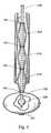
図1は、胃内袋130を胃管腔150内へ給送するための例示的な給送装置100の実施例を示している。給送装置100は、オーバーチューブ110、内側部材140、外側部材120、縫合ビーズ160の穴に通して輪にされている第一の縫合ストランド170及び縫合ビーズ160の穴に通して輪にされている第二の縫合ストランド180を備えている。給送装置100を図示するために、オーバーチューブ110の近位端は図1に示されていない。胃内袋130は外側部材120の表面を覆うように取り付けられた複数の束310(図3)に仕切られており、内側部材140の周囲に同軸状で摺動可能に設けられた状態で示されている。一般的に言うと、給送装置100は押し込み機構196(図1)を備えており、押し込み機構196は、各束310を胃内管腔150内へ個々に進入させることによって制御された方法で胃内袋130を配備させ、図6に示されているような挿入されたアセンブリ600を形式する。束310は、配備された後に、以下において更に詳細に説明するように、圧縮され且つ配向されてドーナツ形状の束610とされる。Example 1
FIG. 1 shows an
押し込み機構196は、以下に更に詳細に説明するように、遠位方向への力を保持部材195(図1)にかけることによって、仕切られた束310の各々を進入させる。図2は押し込み機構196の拡大図である。押し込み機構196は区分181,182,184及び185からなる。区分181,182,184及び185は、非拡張形状(図7)と拡張形状(図1及び図2)との間で動くことができる。区分181,182,184及び185は、内側部材140が露出するように、遠位端において細長い素材を外側部材120から引き離すことによって形成される。外側部材120と内側部材140との遠位端同士は領域183に沿って相互に固定され結合されている。図1、2及び7に示されている実施例においては、遠位端同士は熱接着されている。内側部材140と外側部材120との遠位端同士を固定する他の手段も考えられ、また、それらは当業者によって十分に理解されるであろう。外側部材120の残りの部分は、内側部材140の周りに摺動可能に配置されている。内側部材140を外側部材120に対して近位方向に動かすことによって、区分181,182,184及び185は非拡張形状(図7)から拡張形状(図1)へと動く。内側部材140を外側部材120に対して遠位方向へ動かすことによって、区分181,182,184及び185は、拡張形状(図1)から非拡張形状(図7)へと動く。 The
非拡張形状は、内側部材140の第一の部分166に実質的に平行で且つ隣接している状態の区分181及び184と、内側部材140の第二の部分167に実質的に平行であり且つ隣接している状態の区分182及び185とから構成されている(図7)。区分181,184及び182,185は、各々の内側部材140の第一及び第二の部分166,167に十分に隣接していて、区分181,184及び182,185は、以下において更に詳細に説明するように、保持部材195の内側を後退できるようになされている。 The unexpanded shape is substantially parallel to and adjacent to the
拡張形状(図2)は、外側部材120の第一の部分166から隔てられている状態の区分181及び184と、外側部材120の第二の部分167から隔てられている状態の区分182及び185とから構成されている(図2)。拡張形状における区分181,184及び182,185は、保持部材195の外径より十分大きな横方向距離(図1及び図2)に広がっていて、押し込み機構196の区分181,184及び182,185が束310の保持部材195を押圧して、束310を胃内袋130内から胃内管腔150内へ進入させることができるようになされている。 The expanded shape (FIG. 2) includes
他の押し込み機構も考えられ、それらは当業者によって十分に理解されるであろう。例えば、押し込み機構196はカニュ―レ等を備え、該カニューレ等は、短くされたときに確実に折り畳まれるように予め曲げられている補強ワイヤーを備えていても良い。押し込み機構は拡張形状か非拡張形状に付勢されていても良い。 Other pushing mechanisms are also contemplated and will be well understood by those skilled in the art. For example, the push-in
給送装置100はまた、第一の縫合ストランド170、第二の縫合ストランド180及び縫合ビーズ160を備えている。第一の縫合ストランド170は、縫合ビーズ160の遠位の穴163に通されて輪になっており、第二の縫合ストランド180は、縫合ビーズ160の近位の穴162に通されて輪になっている。第一の縫合ストランド170は、内側部材140内を通って遠位方向に伸長して一番目の配備された束135内に配置されている遠位のボタン197に固定されている(図1)。第一の縫合ストランド170は、近位のボタン198と遠位のボタン197との間を伸長しており且つドーナツ形状の束610のアセンブリを維持する補助となる(図6)。図1には、第二の縫合ストランド180が示されており、該第二の縫合ストランド180は給送装置100の構成要素を視認できるようにするために近位方向へ引っ張り戻された状態である。図1に示されている第一の縫合ストランド170の長さは、約5インチ(12.7センチメートル)で一定のままである。図6の実施例では、約20個の圧潰されたドーナツ形状の束610が5インチ(12.7センチメートル)の第一の縫合ストランド170上に嵌合されて束610の適切な圧縮及びそれに沿った配向が達成されている。第一の縫合ストランド170には実質的に弛みが存在しない。付加的な束610を胃管腔150内へ装入するためには、第一の縫合ストランド170の長さを増すことが必要である。図6の実施例において、更に5個の束610を付加するためには、束610の全ての適正な圧縮及び配向を達成するために約1インチ(2.54センチメートル)の付加的なストランド170が必要とされる。第一の縫合ストランド170上に嵌合される束610の数は変えることができ且つ図6に図示されている実施例に限定することは決して意図されていない。 The
第二の縫合ストランド180は、オーバーチューブ110及ビーズイボースト(touhy borst)アダプタ151から近位方向に伸長して、第一の自由端188及び第二の自由端189として終端している(図5)。第二の縫合ストランド180の第一の自由端188と第二の自由端189とは、以下において更に詳細に説明するように、配備された束135(図1)に張力を維持して好ましいドーナツ形状の束610(図4〜6)の形成を可能にするために主として配備中に使用される。第二の縫合ストランド180は、ドーナツ形状の束610の全てを完全に配備し且つ形成した後に取り外すことができる。縫合ビーズ160は、第一及び第二の縫合ストランド170及び180が通されて輪にされる場所を提供することに加えて、第一の縫合ストランド170に沿って遠位方向へ動かされ、且つ、束610の全てが配備された後に胃内袋130の近位ボタン198上にスナップ嵌合されて、胃内袋130を管腔内に固定する。このことは以下において更に詳細に説明する。
近位の穴162と遠位の穴163とを備えている縫合ビーズ160を示しているが、ビーズ160は、第一及び第二の縫合ストランド170,180を通して伸長させることができる単一の穴を有していても良い。縫合ビーズ160は、如何なる生体適合性の材料によっても作ることができる。一つの実施例においては、ビーズ160はステンレス鋼によって作られている。もう一つの別の実施例においては、ビーズ160は金によって作られている。 Although a
縫合装置100はまたオーバーチューブ110をも備えている。図5を参照すると、オーバーチューブ110は、近位端111と、遠位端112と、胃内袋130及びその他の器具を収容できる構造とされた管腔とを備えている。オーバーチューブ110の遠位端112は、配備プロセス中に胃管腔150内に配置される。オーバーチューブ110の近位端111は患者の体外へと伸長している。オーバーチューブ110の管腔の大きさは、束ねられた胃内袋130の大きさに関係する。オーバーチューブ110は典型的には食道に沿って伸長し、その遠位端112は下部食道括約筋の近くで終端する構造とされている。 The
同じく図5を参照すると、給送装置100はまた、トーイ・ボースト・アダプタ151及びトーイ・ボースト・アダプタ151の側方孔に結合されているハンドポンプ152をも備えている。図5に示されているトーイ・ボースト・アダプタ151は、オーバーチューブ110の近位端の近位側に配置されている。第二の縫合ストランド180の第一の自由端188と第二の自由端189とは、トーイ・ボースト・アダプタ151内を伸長している。ハンドポンプ152は、以下に説明するように、配備された束135を拡張させて圧潰されたドーナツ形状の束610を形成させる。他の器具をトーイ・ボースト・アダプタ151に結合することもできる。 Referring also to FIG. 5, the
給送装置100の構成要素を説明したが、以下においては、胃内袋130を配備させる方法を、非拡張形状(図7)と拡張形状(図2)との間で動くことができる押し込み機構196に関連して説明する。胃内袋130は、外側部材120の周りに装着され且つ仕切られて複数の束310にされる。図3は、外側部材120の周りに装着されている束310を示している。束310は、図3において明確にわかるように、保持部材195(例えば、0リング)を胃内袋130の外周に沿って配置することによって形成される。胃内袋130は、一束ずつ胃内袋130を給送することを容易にするために、保持部材195によって幾つかの束310に仕切られている。保持部材195同士の間隔は、所定の大きさの束310を形成するために選択的に変えることができる。図1の実施例においては、保持部材195は、相対的に約6インチ(15.2センチメートル)離して配置されている。束310は、外側部材120の長手方向の全長に亘っている。 Having described the components of the
胃内袋130を外側部材120上に装着し且つ胃内袋130を束310に仕切り(図3)、そして押し込み機構196は、図7に示されているように非拡張形状にされる。胃内袋130内で非拡張形状(図7)にある押し込み機構196は、図1に示されている最も遠位の保持部材195の近位側に隣接して配置される。この時点で、区分181,184及び182,185は、十分な量だけ外方へ拡張され、区分181,184及び182,185は、図1に示されているように、保持部材195の直径よりも大きな横方向長さに広がる。内側部材140が外側部材120に対して近位方向へ移動すると、区分181、182、184及び185は、非拡張形状(図7)から拡張形状(図1)へと移動せしめられる。押し込み機構196がその拡張形状にある状態では、外側部材120は、遠位方向に進入せしめられて区分181,184及び182,185が保持部材195と接触し且つ保持部材195に遠位方向の十分な力をかけることができる。O−リング195は、胃内袋130の外周に沿って十分緊密に伸長していて、押し込み機構196から遠位方向の力が発生した際にO−リング195が束310に沿って動かないようにされている。O−リングにかかる力は、保持部材195の対応する束310に伝えられて保持部材195の遠位側に配置されている束310(図1)が胃管腔150内へ押し込まれる。 The
押し込み機構196を非拡張形状と拡張形状との間で動かす際に、近位の標識512(図5)は、非拡張状態の押し込み機構196をどこまで後退させるかを目で監視するために使用することができる。遠位の標識513(図5)もまた、拡長状態の押し込み機構196をどこまで進入させるかを目で監視するために使用することができる。 As the
束310を配備した後に、束310は、以下に説明するように圧縮され且つ配向されてドーナツ形状の束610とされる。配備された束135(図1)は、トーイ・ボースト・アダプタ151(図5)に結合されているハンドポンプ152を使用して空気で拡張させることができる。加圧された空気は、トーイ・ボースト・アダプタ151内へ入り且つ外側部材120に沿って遠位方向に移動して配備された束135内へ入る。ハンドポンプ152(図5)によって配備された束135内へ空気を注入することによって、配備された束135は、図1に示されているように拡張する。第二の縫合ストランド180は、配備された束135に張力をかけて配備された束135の各々を圧潰させて円盤形状またはドーナツ形状の束610にするために使用される。特に、第二の縫合ストランド180の自由端188および189は、トーイ・ボースト・アダプタ151を介して近位方向へ引っ張られる。第二の縫合ストランド180は縫合ビーズ160を介して第一の縫合ストランド170に結合されているので、第二の縫合ストランド180の自由端188及び189を引っ張ることによって、第一の縫合ストランド170が近位方向へ引っ張られる。第一の縫合ストランド170は給送装置100全体に沿って遠位方向に伸長しており且つ遠位のボタン197に固定されているので、第一の縫合ストランド170が引っ張られると、拡張せしめられた配備されている束135が圧潰されて拡張された束135内の空気の実質的な部分が除去される。そして、ドーナツ形状の束610(図4〜6)が形成される。束135をドーナツ形状の束610に形成することによって、配備された束610の適切な圧縮及び適正な向きが可能になり、束610の全てを第一の縫合ストランド170の限定された長さに適合させることができる。この実施例においては、胃内袋130は、圧縮されず且つ仕切られていない状態では約6フィート(1.83メートル)の長手方向の長さを有している。ドーナツ形状の束610のアセンブリを形成することによって、このような大量の材料を第一の縫合ストランド170に適合させることができ、これは図6に示されている約6インチ(15.2センチメートル)の最終的な挿入後の長さを有している。 After deploying
束の配備及びドーナツ形状の束の形成中に、縫合ビーズ160が標識199の近位側に配置されていること(図1)を確実にするために、縫合ビーズ160の位置が目視で監視される。縫合ビーズ160のこのような位置決めによって、配備された束610の適切且つ程良い圧縮が可能になり且つ縫合ビーズ160が外側部材120上に装着された束310のうちの一つと絡み合った状態とならないことが確保される。第二の縫合ストランド180の自由端188及び189を引っ張ることによって、束310の各々が押し込み機構196によって胃管腔150内へ押し込まれるときに束310に張力を維持することが可能になる。この段階では、オーバーチューブ110は十分な逆方向に引っ張る力を形成していて、束610が滑ってオーバーチューブ110内へ戻るのが防止され、ドーナツ形状の束610は胃管腔150内の挿入された位置に維持することができる。 During deployment of the bundle and formation of the donut shaped bundle, the position of the
最も遠位の一番目の束135を配備させ且つこれをドーナツ形状の束610に形成すると、次の最も遠位の束310が配備される準備状態となる。押し込み機構196を、次の最も遠位にある配備されるべき束310に結合されている保持部材195の近位側に隣接させて配置するために、押し込み機構196の区分181,184及び182、85が非拡張状態(図7)とされ、押し込み機構196は、保持部材195の内側で引っ張ることができる細い形状をとることができる。この配置は、内側部材140を外側部材120に対して遠位方向に移動させて区分181,182,184及び185を拡張形状(図1)から非拡張形状(図7)へと動かすことによって行なわれる。 Once the most distal
束310は、非拡張状態にある押し込み機構を後退させる際中は、外側部材120に沿った定位置に留まったままである。押し込み機構196を萎ませた後に、押し込み機構196は、近位側に配置されている次の保持部材195の近位側に隣接して配置されるまで近位方向に後退せしめられる。近位の標識512は、押し込み機構196を近位方向にどこまで後退させたかを目で監視する補助となる。押し込み機構196がこのような位置とされた状態で、押し込み機構196を拡張させて保持部材195を押圧させ、最も遠位にある次の束310を胃管腔150内へ押し込むことができる。ハンドポンプ152によって空気を送り込むことによって、この配備された二番目の束135を空気によって膨らませることが可能になる。既に配備させた保持部材195(即ち、最も遠位の保持部材)は胃内袋130の素材の周囲を十分に締め付けていて、空気は既に配備されている最も遠位にある一番目の束内へ流れ込むことはない。第二の縫合ストランド180の自由端188及び189が引っ張られ、配備された二番目の束135が圧潰されて二番目のドーナツ形状の束610が形成される。 The
上記の手順は、外側部材120上に装着されている束310の全てが胃管腔150内へ配備され、その後、程良く圧縮され且つ位置付けされてドーナツ形状の束610にされるまで繰り返される。後続の束310が胃管腔150内へ押し込まれると、挿入されたアセンブリ500(図5)は益々圧縮された状態となる。図4は、束310の全てが外側部材120から配備されているが、圧潰されたドーナツ形状の束610が形成される前の状態を示している。図5は、束310が胃管腔150内に配備され、その後、適正に圧縮され且つ位置決めされてドーナツ形状の束610とされた状態を示している。遠位のボタン197は、遠位端において束610の形状を維持する補助となる。遠位のボタン197は、胃内袋130と同じ材料によって作ることができる。 The above procedure is repeated until all of the
束310の全てを外側部材120から配備させると、外側部材120と内側部材140とは、第二の縫合ストランド180を同時に緊密に保持しながらオーバーチューブ110から取り外される。トーイ・ボースト・アダプタ151が開放され、内側及び外側部材140,120を、縫合ストランド170及び180の外周に沿って且つオーバーチューブ110から外して引っ張り戻すことが可能になる。 When all of the
この時点で、縫合ビーズ160は近位のボタン198に固定されており、近位ボタン198は既に配備されている最も近位のドーナツ形状の束610の近位端607に固定されている(図6)。図4は、第一の縫合ストランド170を縫合ビーズ160の穴に通すことによって縫合ビーズ160はオーバーチューブ110を介して導入されることを示している。押し込み部材が縫合ビーズ160の近位側に導入され、この押し込み部材は、縫合ビーズ160を近位端607にある近位のボタン198に向けて遠位方向に押し、縫合ビーズ160を近位のボタン198にスナップ式に嵌合させる。 At this point, the
縫合ビーズ160を近位のボタン198上に固定すると、挿入された器具500は、図5に示されているように、近位のボタン198と遠位のボタン197との間の定位置に固定される。第二の縫合ストランド180の自由端188と189とのうちの一方を引っ張ることにより、第二の縫合ストランド180は縫合ビーズ160の近位の穴162から取り外すことができる。第二の縫合ストランド180を取り外すと、オーバーチューブ110もまた引っ張り出すことができる。
(実施例2)When the
(Example 2)
区分181、184及び182、185を拡張させたり収縮させたりすることからなる押し込み機構196を使用した上記の配備手順を説明したが、代替的な押し込み機構も考えられる。例えば、図3は、束310を外側部材120から胃管腔150内へ押し込むために使用される拡張可能なバルーン320を示している。押し込み機構196の拡張及び収縮動作と似て、バルーン320は、小さな直径から大きな直径へと形状が変わるようになされている。バルーン320は、外側部材120の遠位端に沿って配置された状態で示されている。図2及び7において押し込み機構に関して各々説明した拡張及び収縮動作と同様に、バルーン320は、サイズが膨張したり収縮したりすることによって拡張した形状を形成して保持部材195及びそれに対応する束310を押す。この拡張した形状は、保持部材195及びそれに対応する束310と接触してこれらを胃管腔150内へと遠位方向に押すのに十分な形状である。遠位の標識513(図5)の使用は、束310を完全に配備するためにバルーン320を押し込む深さを決定する補助となる。これに続いて、バルーン320は、保持部材195の内側を通過できるように十分に萎められるか又は収縮せしめられる。近位の標識512(図5)の使用は、バルーン320を、配備されるべき次の最も遠位にある保持部材195及びそれに対応する束320の近位側に隣接させてバルーン320を位置決めするために萎ませられたバルーン320を後退させる程度を決定する補助となる。 Although the above described deployment procedure using a
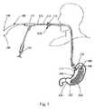
最終的な挿入アセンブリ600のドーナツ形状の束610は、相対的に最少量の空気を含んでいる。空気を束610内へ送り込み且つ第一の縫合ストランド170を引っ張って圧縮されたドーナツ形状の配置を作り上げた後に、空気の実質的な部分は、縫合ビーズ160の近位の穴162及び遠位の穴163を介して出て行くと共にトーイ・ボースト・アダプタ151から出て行く。最終的な挿入アセンブリ600は真空にされる。真空にされることによって、残留している空気が除去されて更に多くの束610を配備することが可能になる。 The donut shaped
図6は、配備された束610からなる最終的な挿入アセンブリ600を示している。アセンブリ600は、胃管腔150内の容積に置き換わるように設計されている。アセンブリ600は、その最終的な挿入状態で、患者の管腔すなわち患者の胃壁と係合したときに満腹感を与える。第一の縫合ストランド170は、近位のボタン198と遠位のボタン197との間に伸長していて、アセンブリ600の束状構造を維持している。ドーナツ形状の束610は、幽門155と十二指腸156とを通って移動するのを実質的に阻止するのに十分なサイズとされている。束610は、十分な大きさであるけれども、折り畳みが実質的に拘束されず且つ自由に動く他の肥満症用器具において典型的に伴う長い径方向の折り畳みを有していない。別の言い方をすると、束状構造610の中心軸線から束610のうちの一つの端縁までの径方向の距離は、鋭い端縁によって帯状に仕切られている肥満症用器具と比較して比較的短い。この結果、互いに隣接している束610間の材料があちこちと動き且つ胃管腔150の壁を刺激する傾向が比較的少ない。更に、径方向での大きな折り畳みを排除することによって、該折り畳まれた部分が蠕動によって十二指腸156(図6)内を前進せしめられることが実質的に阻止される。 FIG. 6 shows the
更に、ドーナツ形状の束610は、比較的鋭い端縁を有している以前の胃内袋からなる挿入器具と比較すると非外傷性である。図6に示されているように、ドーナツ形状の束610の各々の端縁は尖っておらず丸味を付けられている。束610の尖った端縁を排除することによって、潜在的に潰瘍につながる胃の刺激機会が実質的に減らされる。 Furthermore, the donut shaped
アセンブリ600の別の利点は、多数の束310を配備させるのに必要とされる通過させる胃内袋130の数がより少ないことである。コンパクトではなく且つ一連の束に仕切られていない場合の胃内袋130の給送は、長手方向の長さが6フィート(1.83メートル)程度である。このような大きな長さは、大きな容積を占め、従って給送装置100が胃内袋130を完全に配備させるために必要な処置時間が長くなる。束状構造310(図3)は密な構造を形成するので、比較的多数の束を配備させるために必要とされる材料の通過回数が、束状になされていない他の肥満用器具と比較して少ない。 Another advantage of
挿入されたアセンブリ600の束610は、胃管腔150の酸性環境に耐えることができるあらゆる生体適合性材料によって作ることができ、このような材料としては、限定的ではないが、プラスチック、ナイロン、ポリエステル、ポリウレタン、ポリエチレン(例えば、高密度ポリエチレン、低密度ポリエチレン)、ポリアミド、ふっ化エチレンプロピレン及びエチレンビニルアセテートコポリアーがある。束610は、柔軟な又は柔軟でないポリマー材料によって形成することができる。 The
挿入されたアセンブリ600は、十分なダイエット効果が得られたときには所定の期間後に取り除かれる。その場合には、ワイヤーガイドが胃管腔150内へ挿入され、オーバーチューブ110がワイヤーガイドを覆うように装着される。オーバーチューブ110が下部食道括約筋の近くに配置された状態で、ハサミのような切断部材がオーバーチューブ110の管腔を介して配備される。切断部材が近位のボタン198に達すると、切断部材によって近位のボタン198内に捕捉されている第一の縫合ストランド170が切断される。その後に、鉗子がオーバーチューブ110を介して導入され、近位ボタン198が把持されてオーバーチューブ110の管腔を介して引き出される。続いて、スネアが導入されてアセンブリ600の近位端607が捕捉され、束610がオーバーチューブ110から引き出される。 The inserted
本発明のここに示した実施例の種々の部材の構造又は構成の他のあらゆる開示されていない又は付随的な細部は、これらの部材がここに開示されているように行なうのに必要とされる特性を有している限り、本発明の利点を達成するのに重要であるとは考えられていない。これらの及びその他の構造の細部の選択は、本開示に鑑みた場合に、この技術分野の初歩技術者でさえ、その能力の範囲内に十分に含まれるものであると考えられる。以上、本発明の例示的な実施例を実際的な作動構造を開示するためにかなり詳細に説明して本発明を有利に実施することができるようにした。ここに記載された設計は例示的なものであることのみを意図されている。本発明による新規な特徴は、本発明の精神及び範囲から逸脱することなく他の構造形態で組み込むことができる。 Any other undisclosed or attendant details of the structure or construction of the various members of the presently illustrated embodiments of the invention are required to make these members as disclosed herein. As long as it has the following characteristics, it is not considered important to achieve the advantages of the present invention. Selection of these and other structural details are considered well within the capability of even the novice engineer of this field in view of the present disclosure. The exemplary embodiments of the present invention have been described in considerable detail in order to disclose a practical working structure so that the present invention may be advantageously practiced. The design described herein is intended to be exemplary only. The novel features according to the present invention can be incorporated in other structural forms without departing from the spirit and scope of the present invention.
100 給送装置、
110 オーバーチューブ、
111 オーバーチューブ110の近位端、
112 オーバーチューブ110の遠位端、
120 外側部材、
130 胃内袋、
135 一番目の配備された束、
140 内側部材、
150 胃管腔、
151 トーイ・ボースト・アダプタ、
152 ハンドポンプ、
155 幽門、
156 十二指腸、
160 縫合ビーズ、
162 縫合ビーズ160の近位の穴、
163 縫合ビーズ160の遠位の穴、
166 内側部材140の第一の部分、
167 内側部材140の第二の部分、
170 第一の縫合ストランド、
180 第二の縫合ストランド、
181,182,184,185 区分、
183 領域、
188 第二の縫合ストランド180の第一の自由端、
189 第二の縫合ストランド180の第二の自由端、
195 保持部材、O−リング、
196 押し込み機構、
197 遠位のボタン、
198 近位のボタン、
199 標識、
310 複数の束、
320 バルーン、
512 近位の標識、
513 遠位の標識、
600 挿入されたアセンブリ、
607 アセンブリ600の近位端、
610 ドーナツ形状の束、100 feeding device,
110 overtube,
111 proximal end of
112 distal end of
120 outer member,
130 stomach bag,
135 The first deployed bundle,
140 inner member,
150 gastric lumen,
151 Toy Boast Adapter,
152 hand pump,
155 Pylor,
156 duodenum,
160 suture beads,
162 proximal hole of
163, a distal hole in the
166 a first portion of the
167 a second portion of the
170 first suture strand,
180 second suture strand,
181, 182, 184, 185 division,
183 area,
188 the first free end of the
189 the second free end of the
195 holding member, O-ring,
196 pushing mechanism,
197 Distal button,
198 proximal button,
199 signs,
310 multiple bundles,
320 balloon,
512 proximal label,
513 distal label,
600 inserted assembly,
607, the proximal end of
610 donut-shaped bundle,
Claims (20)
Translated fromJapanese近位端と遠位端とを有しているオーバーチューブと、
第一の遠位端を有している内側部材と、
第二の遠位端を有しており且つ前記内側部材の周りに摺動可能に設けられ、前記第二の遠位端に押し込み機構を備えている、外側部材と、
該外側部材の周りに配置され且つ複数の束からなる胃内袋と、を備えており、
前記押し込み機構は、拡張形状と非拡張形状との間で動くことができ、前記拡張形状において前記肥満症用器具を胃管腔内へ一定長さだけ押し込むようになされている、給送装置。A feeding device for introducing an instrument for obesity into the gastric lumen;
An overtube having a proximal end and a distal end;
An inner member having a first distal end;
An outer member having a second distal end and slidably provided about the inner member and comprising a pushing mechanism at the second distal end;
A gastric bag that is disposed around the outer member and includes a plurality of bundles;
The delivery device, wherein the pusher mechanism is movable between an expanded shape and a non-expanded shape and is adapted to push the bariatric device into the gastric lumen for a certain length in the expanded shape.
前記縫合ビーズに通して輪にされ且つ前記内側部材に沿って近位方向に伸長し、且つ前記内側部材の近位端において第一の自由端及び第二の自由端で終端している第二の縫合ストランドと、を更に備えている、請求項1に記載の給送装置。A first suture strand that loops through a suture bead and extends to a distal button disposed at a distal end of the bariatric device and secured to the distal button;
A second looped through the suture bead and extending proximally along the inner member and terminating at a first free end and a second free end at a proximal end of the inner member; The feeding device according to claim 1, further comprising: a suture strand.
(a)近位端と遠位端とを有しているオーバーチューブと、
第一の遠位端を有している内側部材と、
第二の遠位端を有しており且つ前記内側部材の周りに摺動可能に設けられ、前記第二の遠位端に押し込み機構を備えている外側部材と、を備え、
前記押し込み機構は、拡張形状と非拡張形状との間で動くことができ、前記拡張形状においては、前記胃内袋を胃管腔内へ一定長さ押し込むのに十分な距離だけ広がるようになされてなる、給送装置を準備するステップと、
(b)束の周りに周方向に配置され且つ相対的に所定の距離だけ隔てられている複数の保持部材によって、前記胃内袋を複数の束に仕切るステップと、
(c)前記胃内袋を前記外側部材の周りに装着するステップと、
(d)前記外側部材を近位方向へ引っ張って、前記複数の保持部材のうちの一番目の保持部材を通過させ、前記押し込み機構が非拡張形状とされており且つ前記一番目の保持部材の近位側に隣接している前記袋内に配置されるようにするステップと、
(e)前記押し込み機構を拡張させるステップと、
(f)前記外側部材を遠位方向に移動させて、前記一番目の保持部材を前記複数の保持部材から押し出し且つ前記複数の束のうちの一番目の束を胃管腔内へ押し出すステップと、
を含む方法。It is a method of introducingthe stomach bag intothe stomach lumenof animals other than humans ,
(A) an overtube having a proximal end and a distal end;
An inner member having a first distal end;
An outer member having a second distal end and slidably provided about the inner member and comprising a pushing mechanism at the second distal end;
The pusher mechanism can move between an expanded shape and a non-expanded shape, and in the expanded shape, the pusher mechanism is configured to expand a distance sufficient to push the stomach bag into the gastric lumen for a certain length. Preparing a feeding device comprising:
(B) partitioning the stomach bag into a plurality of bundles by a plurality of holding members disposed circumferentially around the bundle and relatively spaced apart by a predetermined distance;
(C) wearing the stomach bag around the outer member;
(D) Pulling the outer member proximally to pass the first holding member out of the plurality of holding members, the push-in mechanism is non-expanded, and the first holding member Being disposed within the bag adjacent proximally;
(E) expanding the pushing mechanism;
(F) moving the outer member in the distal direction to push out the first holding member from the plurality of holding members and push the first bundle out of the plurality of bundles into the gastric lumen; ,
Including methods.
(h)前記外側部材を近位方向へ引っ張って、前記複数の保持部材のうちの二番目の保持部材を通過させ、前記押し込み機構が非拡張形状とされており且つ前記複数の保持部材からの前記二番目の保持部材の近位側に隣接している前記袋内に配置されるようにするステップと、
(i)前記押し込み機構を拡張させるステップと、
(j)前記外側部材を遠位方向へ動かすステップと、
(k)前記二番目の保持部材を前記複数の保持部材から押し出して、前記複数の束のうちの二番目の束を胃管腔内へ押し込むステップと、
を更に含んでいる請求項13に記載の方法。(G) making the pushing mechanism non-expandable;
(H) Pulling the outer member in the proximal direction to pass the second holding member out of the plurality of holding members, and the push-in mechanism has a non-expanded shape, and from the plurality of holding members Being disposed within the bag adjacent to the proximal side of the second retaining member;
(I) expanding the pushing mechanism;
(J) moving the outer member distally;
(K) extruding the second holding member from the plurality of holding members and pushing the second bundle of the plurality of bundles into the gastric lumen;
14. The method of claim 13, further comprising:
前記縫合ビーズに通して輪にされ且つ前記内側部材に沿って近位方向に伸長し、前記内側部材の近位端において第一の自由端と第二の自由端とで終端している第二の縫合ストランドと、を準備するステップと、
(h)空気を前記一番目の束内へ注入するステップと、
(i)前記第二の縫合ストランドの第一及び第二の自由端を引っ張って、前記一番目の束が前記胃管腔内に第一の圧潰したドーナツ形状を形成するようにさせるステップと、
を更に含んでいる請求項13に記載の方法。(G) a first suture strand looped through the suture bead and extending to the distal button of the instrument and secured to the distal button located at the distal end of the bag;
A second looped through the suture bead and extending proximally along the inner member and terminating at a first free end and a second free end at a proximal end of the inner member; Preparing a suture strand; and
(H) injecting air into the first bundle;
(I) pulling the first and second free ends of the second suture strand so that the first bundle forms a first collapsed donut shape in the gastric lumen;
14. The method of claim 13, further comprising:
前記縫合ビーズに通して輪にされ且つ前記内側部材に沿って近位方向に伸長し、前記内側部材の近位端において第一の自由端と第二の自由端とで終端している第二の縫合ストランドと、を準備するステップと、
(m)空気を前記一番目の束内へ注入するステップと、
(n)前記第二の縫合ストランドの第一及び第二の自由端を引っ張って、二番目の束が前記胃管腔内に二番目の圧潰したドーナツ形状を形成し、前記二番目の束が前記第一の束に隣接するようにさせるステップと、
を更に含んでいる請求項14に記載の方法。(L) a first suture strand looped through a suture bead and extending to a distal button of the instrument and secured to a distal button located at the distal end of the bag;
A second looped through the suture bead and extending proximally along the inner member and terminating at a first free end and a second free end at a proximal end of the inner member; Preparing a suture strand; and
(M) injecting air into the first bundle;
(N) Pulling the first and second free ends of the second suture strand, the second bundle forms a second collapsed donut shape in the gastric lumen, and the second bundle Adjoining the first bundle;
15. The method of claim 14, further comprising:
(k)前記第一の縫合ストランドを近位のボタンに通すステップと、
(l)前記近位のボタンを前記縫合ビーズにスナップ式に嵌合させるステップと、
を更に含んでいる請求項17に記載の方法。(J) pulling out the outer member;
(K) threading the first suture strand through a proximal button;
(L) snapping the proximal button into the suture bead;
The method of claim 17, further comprising:
(n)前記第二の縫合ストランドを取り出すステップと、
を更に含んでいる請求項19に記載の方法。(M) detaching the first and second free ends of the second suture strand from the proximal button;
(N) removing the second suture strand;
20. The method of claim 19, further comprising:
Applications Claiming Priority (3)
| Application Number | Priority Date | Filing Date | Title |
|---|---|---|---|
| US11/965,531 | 2007-12-27 | ||
| US11/965,531US8016851B2 (en) | 2007-12-27 | 2007-12-27 | Delivery system and method of delivery for treating obesity |
| PCT/US2008/086975WO2009085747A1 (en) | 2007-12-27 | 2008-12-16 | Delivery system for intragastric bag |
Publications (3)
| Publication Number | Publication Date |
|---|---|
| JP2011508630A JP2011508630A (en) | 2011-03-17 |
| JP2011508630A5 JP2011508630A5 (en) | 2012-02-09 |
| JP5276117B2true JP5276117B2 (en) | 2013-08-28 |
Family
ID=40436384
Family Applications (1)
| Application Number | Title | Priority Date | Filing Date |
|---|---|---|---|
| JP2010540780AExpired - Fee RelatedJP5276117B2 (en) | 2007-12-27 | 2008-12-16 | Intragastric bag feeder |
Country Status (7)
| Country | Link |
|---|---|
| US (1) | US8016851B2 (en) |
| EP (1) | EP2224888B1 (en) |
| JP (1) | JP5276117B2 (en) |
| AT (1) | ATE550002T1 (en) |
| AU (1) | AU2008343329B2 (en) |
| CA (1) | CA2710755C (en) |
| WO (1) | WO2009085747A1 (en) |
Families Citing this family (21)
| Publication number | Priority date | Publication date | Assignee | Title |
|---|---|---|---|---|
| US9974680B2 (en) | 2004-12-27 | 2018-05-22 | Spatz Fgia, Inc. | System and methods for internalization of external components of adjustable intragastric balloon |
| WO2014082044A1 (en) | 2012-11-26 | 2014-05-30 | Spatz Fgia, Inc. | System and methods for internalization of components of an adjustable intragastric balloon |
| EP2004269B1 (en)* | 2006-03-28 | 2016-08-10 | Spatz-Fgia Inc. | Floating gastrointestinal anchor |
| EP2099385B1 (en) | 2006-11-27 | 2021-02-24 | Davol Inc. | A device especially useful for hernia repair surgeries |
| EP2995276B1 (en) | 2007-10-17 | 2017-07-05 | Davol, Inc. | Fixating means between a mesh and mesh deployment means especially useful for hernia repair surgeries |
| MX2010008003A (en)* | 2008-01-29 | 2010-09-24 | Milux Holding Sa | Apparatus for treating obesity. |
| US8920445B2 (en) | 2008-05-07 | 2014-12-30 | Davol, Inc. | Method and apparatus for repairing a hernia |
| CA2744206C (en) | 2008-11-21 | 2019-05-21 | C.R. Bard, Inc. | Soft tissue repair prosthesis, expandable device, and method of soft tissue repair |
| US20100249822A1 (en)* | 2009-03-31 | 2010-09-30 | Raj Nihalani | Method and apparatus for treating obesity and controlling weight gain using adjustable intragastric devices |
| WO2011045785A1 (en)* | 2009-10-13 | 2011-04-21 | Spatz Fgia, Inc. | Balloon hydraulic and gaseous expansion system |
| WO2012047414A1 (en) | 2010-10-05 | 2012-04-12 | C.R. Bard, Inc. | Soft tissue repair prosthesis and expandable device |
| US9233016B2 (en)* | 2010-10-18 | 2016-01-12 | Apollo Endosurgery, Inc. | Elevating stomach stimulation device |
| ES2565348T3 (en)* | 2010-10-18 | 2016-04-04 | Apollo Endosurgery, Inc. | Intragastric implant reagent devices |
| US8870966B2 (en) | 2010-10-18 | 2014-10-28 | Apollo Endosurgery, Inc. | Intragastric balloon for treating obesity |
| US8920447B2 (en)* | 2010-10-19 | 2014-12-30 | Apollo Endosurgery, Inc. | Articulated gastric implant clip |
| US10159425B2 (en)* | 2013-11-08 | 2018-12-25 | Covidien Lp | Devices and methods facilitating sleeve gastrectomy and other procedures |
| US9918863B2 (en) | 2013-11-13 | 2018-03-20 | Covidien Lp | Steerable gastric calibration tube |
| US9775735B2 (en) | 2014-01-31 | 2017-10-03 | Covidien Lp | Gastric calibration tube |
| BR112019016422A2 (en) | 2017-02-09 | 2020-04-07 | Spatz FGIA Ltd | check valve with gastrointestinal balloon docking station |
| CN108464945B (en)* | 2018-05-03 | 2024-03-22 | 杭州糖吉医疗科技有限公司 | A duodenal built-in jejunal cannula release system and its use method |
| CN113226225A (en) | 2018-12-21 | 2021-08-06 | 斯帕茨菲亚有限公司 | Valve with docking for gastrointestinal balloon |
Family Cites Families (134)
| Publication number | Priority date | Publication date | Assignee | Title |
|---|---|---|---|---|
| US2508690A (en)* | 1948-07-13 | 1950-05-23 | Schmerl Egon Fritz | Gastrointestinal tube |
| US4133315A (en)* | 1976-12-27 | 1979-01-09 | Berman Edward J | Method and apparatus for reducing obesity |
| US4315509A (en)* | 1977-01-10 | 1982-02-16 | Smit Julie A | Insertion and removal catheters and intestinal tubes for restricting absorption |
| US4134405A (en)* | 1977-01-10 | 1979-01-16 | Smit Julie A | Catheter and intestine tube and method of using the same |
| US4246893A (en)* | 1978-07-05 | 1981-01-27 | Daniel Berson | Inflatable gastric device for treating obesity |
| US4416267A (en)* | 1981-12-10 | 1983-11-22 | Garren Lloyd R | Method and apparatus for treating obesity |
| US4899747A (en) | 1981-12-10 | 1990-02-13 | Garren Lloyd R | Method and appartus for treating obesity |
| US4403604A (en) | 1982-05-13 | 1983-09-13 | Wilkinson Lawrence H | Gastric pouch |
| US4447227A (en)* | 1982-06-09 | 1984-05-08 | Endoscopy Surgical Systems, Inc. | Multi-purpose medical devices |
| US4485805A (en)* | 1982-08-24 | 1984-12-04 | Gunther Pacific Limited Of Hong Kong | Weight loss device and method |
| US4558699A (en) | 1983-01-03 | 1985-12-17 | Bashour Samuel B | Method of and apparatus for restricting the passage of food through the stomach |
| US4512338A (en)* | 1983-01-25 | 1985-04-23 | Balko Alexander B | Process for restoring patency to body vessels |
| US4607618A (en)* | 1983-02-23 | 1986-08-26 | Angelchik Jean P | Method for treatment of morbid obesity |
| US4952339A (en)* | 1985-03-22 | 1990-08-28 | Nuclear Packaging, Inc. | Dewatering nuclear wastes |
| US4723547A (en)* | 1985-05-07 | 1988-02-09 | C. R. Bard, Inc. | Anti-obesity balloon placement system |
| US4696288A (en) | 1985-08-14 | 1987-09-29 | Kuzmak Lubomyr I | Calibrating apparatus and method of using same for gastric banding surgery |
| US4694827A (en)* | 1986-01-14 | 1987-09-22 | Weiner Brian C | Inflatable gastric device for treating obesity and method of using the same |
| GB8603099D0 (en) | 1986-02-07 | 1986-03-12 | Blass K G | Gastrointestinal module |
| US4803985A (en)* | 1986-02-14 | 1989-02-14 | Hill Carl W | Gastroplasty method |
| JP2691937B2 (en)* | 1988-07-05 | 1997-12-17 | カンテニース,ジョゼ | Intragastric balloon |
| US4925446A (en)* | 1988-07-06 | 1990-05-15 | Transpharm Group Inc. | Removable inflatable intragastrointestinal device for delivering beneficial agents |
| US4983167A (en)* | 1988-11-23 | 1991-01-08 | Harvinder Sahota | Balloon catheters |
| US5265622A (en)* | 1990-10-25 | 1993-11-30 | C. R. Bard, Inc. | Guidewire having radially expandable member and method for guiding and advancing a catheter using the same |
| US5370134A (en)* | 1991-05-29 | 1994-12-06 | Orgin Medsystems, Inc. | Method and apparatus for body structure manipulation and dissection |
| US5234454A (en)* | 1991-08-05 | 1993-08-10 | Akron City Hospital | Percutaneous intragastric balloon catheter and method for controlling body weight therewith |
| US5246456A (en) | 1992-06-08 | 1993-09-21 | Wilkinson Lawrence H | Fenestrated gastric pouch |
| US5345949A (en) | 1992-09-02 | 1994-09-13 | Shlain Leonard M | Methods for use in surgical gastroplastic procedure |
| US5327914A (en)* | 1992-09-02 | 1994-07-12 | Shlain Leonard M | Method and devices for use in surgical gastroplastic procedure |
| US5306300A (en)* | 1992-09-22 | 1994-04-26 | Berry H Lee | Tubular digestive screen |
| US5985307A (en)* | 1993-04-14 | 1999-11-16 | Emory University | Device and method for non-occlusive localized drug delivery |
| US5507769A (en)* | 1994-10-18 | 1996-04-16 | Stentco, Inc. | Method and apparatus for forming an endoluminal bifurcated graft |
| ATE196742T1 (en)* | 1994-06-24 | 2000-10-15 | Schneider Europ Gmbh | MEDICINAL DEVICE FOR THE TREATMENT OF A PART OF A BODY VESSEL USING IONIZATION RADIATION |
| US5547458A (en)* | 1994-07-11 | 1996-08-20 | Ethicon, Inc. | T-shaped abdominal wall lift with telescoping member |
| US5779688A (en)* | 1994-10-28 | 1998-07-14 | Intella Interventional Systems, Inc. | Low profile balloon-on-a-wire catheter with shapeable and/or deflectable tip and method |
| US5766203A (en)* | 1995-07-20 | 1998-06-16 | Intelliwire, Inc. | Sheath with expandable distal extremity and balloon catheters and stents for use therewith and method |
| US5827304A (en)* | 1995-11-16 | 1998-10-27 | Applied Medical Resources Corporation | Intraluminal extraction catheter |
| IL128261A0 (en)* | 1999-01-27 | 1999-11-30 | Disc O Tech Medical Tech Ltd | Expandable element |
| US5938669A (en) | 1997-05-07 | 1999-08-17 | Klasamed S.A. | Adjustable gastric banding device for contracting a patient's stomach |
| US5868141A (en)* | 1997-05-14 | 1999-02-09 | Ellias; Yakub A. | Endoscopic stomach insert for treating obesity and method for use |
| DE19739031A1 (en)* | 1997-09-05 | 1999-03-11 | Suwelack Nachf Dr Otto | Oral administration agent, its preparation and use |
| WO1999016499A1 (en)* | 1997-10-01 | 1999-04-08 | Boston Scientific Corporation | Dilation systems and related methods |
| US5993473A (en) | 1997-11-19 | 1999-11-30 | Chan; Yung C. | Expandable body device for the gastric cavity and method |
| US20010020150A1 (en)* | 1998-02-06 | 2001-09-06 | Biagio Ravo | Inflatable intraluminal molding device |
| US6210347B1 (en)* | 1998-08-13 | 2001-04-03 | Peter Forsell | Remote control food intake restriction device |
| US6460543B1 (en) | 1998-08-13 | 2002-10-08 | Obtech Medical Ag | Non-injection port food intake restriction device |
| US6067991A (en)* | 1998-08-13 | 2000-05-30 | Forsell; Peter | Mechanical food intake restriction device |
| US6366814B1 (en)* | 1998-10-26 | 2002-04-02 | Birinder R. Boveja | External stimulator for adjunct (add-on) treatment for neurological, neuropsychiatric, and urological disorders |
| US6427089B1 (en)* | 1999-02-19 | 2002-07-30 | Edward W. Knowlton | Stomach treatment apparatus and method |
| IL129032A (en) | 1999-03-17 | 2006-12-31 | Moshe Dudai | Gastric band |
| US6454699B1 (en) | 2000-02-11 | 2002-09-24 | Obtech Medical Ag | Food intake restriction with controlled wireless energy supply |
| EP1211988B1 (en) | 1999-08-12 | 2010-02-17 | Potencia Medical AG | Stoma opening forming apparatus |
| FR2802407B1 (en)* | 1999-12-21 | 2002-12-13 | Rc Medical | DESERRABLE GASTROPLASTY RING |
| FR2804011B1 (en) | 2000-01-20 | 2002-07-19 | Rc Medical | SINGLE CONTROL GASTROPLASTY RING |
| US6450946B1 (en) | 2000-02-11 | 2002-09-17 | Obtech Medical Ag | Food intake restriction with wireless energy transfer |
| FR2805986B1 (en)* | 2000-03-13 | 2002-10-11 | Districlass Madical | INTRA-GASTRIC DEVICE WITH VARIABLE VOLUME |
| FR2808674B1 (en)* | 2000-05-12 | 2002-08-02 | Cie Euro Etude Rech Paroscopie | GASTROPLASTY RING WITH GRIPPED LEGS |
| US6540789B1 (en)* | 2000-06-15 | 2003-04-01 | Scimed Life Systems, Inc. | Method for treating morbid obesity |
| US7033373B2 (en)* | 2000-11-03 | 2006-04-25 | Satiety, Inc. | Method and device for use in minimally invasive placement of space-occupying intragastric devices |
| US20060206160A1 (en) | 2000-11-15 | 2006-09-14 | Transneuronix, Inc. | Process and electrostimulation device for treating obesity and/or gastroesophageal reflux disease |
| EP1366716B1 (en)* | 2001-03-09 | 2005-04-27 | José Rafael Garza Alvarez | Intragastric balloon assembly |
| JP4255286B2 (en)* | 2001-05-17 | 2009-04-15 | ウィルソン−クック メディカル インコーポレイテッド | Intragastric device for treating obesity |
| WO2002096325A1 (en)* | 2001-05-27 | 2002-12-05 | Schurr Marc O | Medical implant |
| US6558400B2 (en)* | 2001-05-30 | 2003-05-06 | Satiety, Inc. | Obesity treatment tools and methods |
| US20020188354A1 (en) | 2001-06-12 | 2002-12-12 | Peghini Paolo Lino | Device to treat obesity by obstructing gastric outlet |
| US6511490B2 (en)* | 2001-06-22 | 2003-01-28 | Antoine Jean Henri Robert | Gastric banding device and method |
| US6627206B2 (en) | 2001-07-25 | 2003-09-30 | Greg A. Lloyd | Method and apparatus for treating obesity and for delivering time-released medicaments |
| US20040117031A1 (en)* | 2001-08-27 | 2004-06-17 | Stack Richard S. | Satiation devices and methods |
| US6845776B2 (en)* | 2001-08-27 | 2005-01-25 | Richard S. Stack | Satiation devices and methods |
| US6675809B2 (en) | 2001-08-27 | 2004-01-13 | Richard S. Stack | Satiation devices and methods |
| US7097665B2 (en)* | 2003-01-16 | 2006-08-29 | Synecor, Llc | Positioning tools and methods for implanting medical devices |
| US6740121B2 (en)* | 2001-11-09 | 2004-05-25 | Boston Scientific Corporation | Intragastric stent for duodenum bypass |
| US6755869B2 (en)* | 2001-11-09 | 2004-06-29 | Boston Scientific Corporation | Intragastric prosthesis for the treatment of morbid obesity |
| US6733512B2 (en)* | 2002-03-07 | 2004-05-11 | Mcghan Jim J. | Self-deflating intragastric balloon |
| US7335210B2 (en)* | 2002-04-03 | 2008-02-26 | Julie Ann Smit | Endoscope and tools for applying sealants and adhesives and intestinal lining for reducing food absorption |
| US7146984B2 (en) | 2002-04-08 | 2006-12-12 | Synecor, Llc | Method and apparatus for modifying the exit orifice of a satiation pouch |
| JP2005524485A (en) | 2002-05-09 | 2005-08-18 | ディー.イーガン トマス | Gastric bypass prosthesis |
| US20040019388A1 (en)* | 2002-07-24 | 2004-01-29 | Starkebaum Warren L. | Methods and implants for retarding stomach emptying to treat eating disorders |
| US6746460B2 (en)* | 2002-08-07 | 2004-06-08 | Satiety, Inc. | Intra-gastric fastening devices |
| US7338433B2 (en) | 2002-08-13 | 2008-03-04 | Allergan, Inc. | Remotely adjustable gastric banding method |
| US7211114B2 (en)* | 2002-08-26 | 2007-05-01 | The Trustees Of Columbia University In The City Of New York | Endoscopic gastric bypass |
| DK1553878T3 (en) | 2002-08-28 | 2010-05-31 | Allergan Inc | Fatigue resistant gastric banding device |
| US6981978B2 (en)* | 2002-08-30 | 2006-01-03 | Satiety, Inc. | Methods and devices for maintaining a space occupying device in a relatively fixed location within a stomach |
| US7214233B2 (en)* | 2002-08-30 | 2007-05-08 | Satiety, Inc. | Methods and devices for maintaining a space occupying device in a relatively fixed location within a stomach |
| US7033384B2 (en)* | 2002-08-30 | 2006-04-25 | Satiety, Inc. | Stented anchoring of gastric space-occupying devices |
| US7220237B2 (en)* | 2002-10-23 | 2007-05-22 | Satiety, Inc. | Method and device for use in endoscopic organ procedures |
| US7229428B2 (en)* | 2002-10-23 | 2007-06-12 | Satiety, Inc. | Method and device for use in endoscopic organ procedures |
| US9060844B2 (en)* | 2002-11-01 | 2015-06-23 | Valentx, Inc. | Apparatus and methods for treatment of morbid obesity |
| US7794447B2 (en)* | 2002-11-01 | 2010-09-14 | Valentx, Inc. | Gastrointestinal sleeve device and methods for treatment of morbid obesity |
| US7037344B2 (en) | 2002-11-01 | 2006-05-02 | Valentx, Inc. | Apparatus and methods for treatment of morbid obesity |
| US7837669B2 (en)* | 2002-11-01 | 2010-11-23 | Valentx, Inc. | Devices and methods for endolumenal gastrointestinal bypass |
| US20090149871A9 (en) | 2002-11-01 | 2009-06-11 | Jonathan Kagan | Devices and methods for treating morbid obesity |
| US8070743B2 (en) | 2002-11-01 | 2011-12-06 | Valentx, Inc. | Devices and methods for attaching an endolumenal gastrointestinal implant |
| US6656194B1 (en) | 2002-11-05 | 2003-12-02 | Satiety, Inc. | Magnetic anchoring devices |
| US7695446B2 (en)* | 2002-12-02 | 2010-04-13 | Gi Dynamics, Inc. | Methods of treatment using a bariatric sleeve |
| US7037343B2 (en)* | 2002-12-23 | 2006-05-02 | Python, Inc. | Stomach prosthesis |
| US20040143342A1 (en)* | 2003-01-16 | 2004-07-22 | Stack Richard S. | Satiation pouches and methods of use |
| US20060015151A1 (en)* | 2003-03-14 | 2006-01-19 | Aldrich William N | Method of using endoscopic truncal vagoscopy with gastric bypass, gastric banding and other procedures |
| US7291160B2 (en) | 2003-03-17 | 2007-11-06 | Delegge Rebecca | Intragastric catheter |
| US6981980B2 (en)* | 2003-03-19 | 2006-01-03 | Phagia Technology | Self-inflating intragastric volume-occupying device |
| ATE422858T1 (en) | 2003-03-28 | 2009-03-15 | Gi Dynamics Inc | ANTI-OBESITY DEVICES |
| US7175638B2 (en)* | 2003-04-16 | 2007-02-13 | Satiety, Inc. | Method and devices for modifying the function of a body organ |
| US20060074450A1 (en)* | 2003-05-11 | 2006-04-06 | Boveja Birinder R | System for providing electrical pulses to nerve and/or muscle using an implanted stimulator |
| US7731757B2 (en) | 2003-06-01 | 2010-06-08 | Reflux Corporation | Obesity treatment |
| US7054690B2 (en)* | 2003-10-22 | 2006-05-30 | Intrapace, Inc. | Gastrointestinal stimulation device |
| US7261730B2 (en)* | 2003-11-14 | 2007-08-28 | Lumerx, Inc. | Phototherapy device and system |
| US7177693B2 (en)* | 2004-01-07 | 2007-02-13 | Medtronic, Inc. | Gastric stimulation for altered perception to treat obesity |
| US20050149142A1 (en)* | 2004-01-07 | 2005-07-07 | Starkebaum Warren L. | Gastric stimulation responsive to sensing feedback |
| US7931693B2 (en) | 2004-02-26 | 2011-04-26 | Endosphere, Inc. | Method and apparatus for reducing obesity |
| US20050209653A1 (en) | 2004-03-16 | 2005-09-22 | Medtronic, Inc. | Intra-luminal device for gastrointestinal electrical stimulation |
| WO2006049725A2 (en)* | 2004-03-23 | 2006-05-11 | Minimus Surgical Systems | Surgical systems and devices to enhance gastric restriction therapies |
| US20050222637A1 (en) | 2004-03-30 | 2005-10-06 | Transneuronix, Inc. | Tachygastrial electrical stimulation |
| US20050222638A1 (en) | 2004-03-30 | 2005-10-06 | Steve Foley | Sensor based gastrointestinal electrical stimulation for the treatment of obesity or motility disorders |
| US20050246037A1 (en) | 2004-04-30 | 2005-11-03 | Medtronic, Inc. | Partial esophageal obstruction to limit food intake for treatment of obesity |
| US20050245957A1 (en) | 2004-04-30 | 2005-11-03 | Medtronic, Inc. | Biasing stretch receptors in stomach wall to treat obesity |
| WO2005107641A2 (en)* | 2004-05-03 | 2005-11-17 | Fulfillium, Inc. | Method and system for gastric volume control |
| US7112186B2 (en) | 2004-05-26 | 2006-09-26 | Shah Tilak M | Gastro-occlusive device |
| US20050277975A1 (en)* | 2004-06-09 | 2005-12-15 | Usgi Medical Corp. | Methods and apparatus for creating a working space within a body lumen or cavity |
| US20060058892A1 (en)* | 2004-09-16 | 2006-03-16 | Lesh Michael D | Valved tissue augmentation implant |
| US20070078476A1 (en)* | 2004-10-12 | 2007-04-05 | Hull Wendell C Sr | Overweight control apparatuses for insertion into the stomach |
| EP1669045B1 (en)* | 2004-12-09 | 2012-04-11 | AMI Agency for Medical Innovations GmbH | Gastric band for the treatment of obesity |
| US7984717B2 (en) | 2005-04-29 | 2011-07-26 | Medtronic, Inc. | Devices for augmentation of lumen walls |
| US20060257444A1 (en) | 2005-04-29 | 2006-11-16 | Medtronic, Inc. | Devices for augmentation of lumen walls |
| US20060257445A1 (en) | 2005-04-29 | 2006-11-16 | Medtronic, Inc. | Devices for augmentation of lumen walls |
| US7674271B2 (en) | 2005-05-04 | 2010-03-09 | InTailor Surgical, Inc. | Endoluminal gastric ring and method |
| AU2006244211B2 (en)* | 2005-05-09 | 2011-03-10 | Cook Medical Technologies Llc | Intragastric device for treating obesity |
| US8216266B2 (en)* | 2005-06-16 | 2012-07-10 | Hively Robert L | Gastric bariatric apparatus with selective inflation and safety features |
| US20050240239A1 (en) | 2005-06-29 | 2005-10-27 | Boveja Birinder R | Method and system for gastric ablation and gastric pacing to provide therapy for obesity, motility disorders, or to induce weight loss |
| US7871416B2 (en)* | 2005-07-22 | 2011-01-18 | Phillips Edward H | Clamp device to plicate the stomach |
| DE102005034529A1 (en)* | 2005-07-23 | 2007-01-25 | Qualimed Innovative Medizinprodukte Gmbh | balloon dilatation catheter |
| JP4880262B2 (en)* | 2005-08-11 | 2012-02-22 | オリンパスメディカルシステムズ株式会社 | Intragastric balloon |
| US20070100369A1 (en)* | 2005-10-31 | 2007-05-03 | Cragg Andrew H | Intragastric space filler |
| US20070100368A1 (en)* | 2005-10-31 | 2007-05-03 | Quijano Rodolfo C | Intragastric space filler |
| EP1968506B1 (en)* | 2005-12-22 | 2011-09-14 | Wilson-Cook Medical Inc. | Coiled intragastric member for treating obesity |
| US20080109027A1 (en)* | 2006-08-01 | 2008-05-08 | Fulfillium, Inc. | Method and system for gastric volume control |
- 2007
- 2007-12-27USUS11/965,531patent/US8016851B2/enactiveActive
- 2008
- 2008-12-16CACA2710755Apatent/CA2710755C/enactiveActive
- 2008-12-16AUAU2008343329Apatent/AU2008343329B2/ennot_activeCeased
- 2008-12-16ATAT08866823Tpatent/ATE550002T1/enactive
- 2008-12-16WOPCT/US2008/086975patent/WO2009085747A1/enactiveApplication Filing
- 2008-12-16JPJP2010540780Apatent/JP5276117B2/ennot_activeExpired - Fee Related
- 2008-12-16EPEP08866823Apatent/EP2224888B1/enactiveActive
Also Published As
| Publication number | Publication date |
|---|---|
| AU2008343329A1 (en) | 2009-07-09 |
| US20090171382A1 (en) | 2009-07-02 |
| CA2710755A1 (en) | 2009-07-09 |
| JP2011508630A (en) | 2011-03-17 |
| EP2224888A1 (en) | 2010-09-08 |
| EP2224888B1 (en) | 2012-03-21 |
| WO2009085747A1 (en) | 2009-07-09 |
| ATE550002T1 (en) | 2012-04-15 |
| CA2710755C (en) | 2012-12-04 |
| US8016851B2 (en) | 2011-09-13 |
| AU2008343329B2 (en) | 2013-10-03 |
Similar Documents
| Publication | Publication Date | Title |
|---|---|---|
| JP5276117B2 (en) | Intragastric bag feeder | |
| JP5469611B2 (en) | Gastric appliance | |
| US7066945B2 (en) | Intragastric device for treating obesity | |
| US8216268B2 (en) | Intragastric bag for treating obesity | |
| CA2634614C (en) | Coiled intragastric member for treating obesity | |
| JP4996598B2 (en) | Intragastric device for the treatment of obesity | |
| AU2002305631A1 (en) | Intragastric device for treating obesity | |
| HK1067519B (en) | Intragastric device for treating obesity |
Legal Events
| Date | Code | Title | Description |
|---|---|---|---|
| A521 | Request for written amendment filed | Free format text:JAPANESE INTERMEDIATE CODE: A523 Effective date:20111215 | |
| A621 | Written request for application examination | Free format text:JAPANESE INTERMEDIATE CODE: A621 Effective date:20111215 | |
| A711 | Notification of change in applicant | Free format text:JAPANESE INTERMEDIATE CODE: A711 Effective date:20120302 | |
| TRDD | Decision of grant or rejection written | ||
| A01 | Written decision to grant a patent or to grant a registration (utility model) | Free format text:JAPANESE INTERMEDIATE CODE: A01 Effective date:20130423 | |
| A977 | Report on retrieval | Free format text:JAPANESE INTERMEDIATE CODE: A971007 Effective date:20130425 | |
| A61 | First payment of annual fees (during grant procedure) | Free format text:JAPANESE INTERMEDIATE CODE: A61 Effective date:20130516 | |
| R150 | Certificate of patent or registration of utility model | Free format text:JAPANESE INTERMEDIATE CODE: R150 Ref document number:5276117 Country of ref document:JP Free format text:JAPANESE INTERMEDIATE CODE: R150 | |
| R250 | Receipt of annual fees | Free format text:JAPANESE INTERMEDIATE CODE: R250 | |
| R250 | Receipt of annual fees | Free format text:JAPANESE INTERMEDIATE CODE: R250 | |
| R250 | Receipt of annual fees | Free format text:JAPANESE INTERMEDIATE CODE: R250 | |
| R250 | Receipt of annual fees | Free format text:JAPANESE INTERMEDIATE CODE: R250 | |
| R250 | Receipt of annual fees | Free format text:JAPANESE INTERMEDIATE CODE: R250 | |
| R250 | Receipt of annual fees | Free format text:JAPANESE INTERMEDIATE CODE: R250 | |
| R250 | Receipt of annual fees | Free format text:JAPANESE INTERMEDIATE CODE: R250 | |
| R250 | Receipt of annual fees | Free format text:JAPANESE INTERMEDIATE CODE: R250 | |
| LAPS | Cancellation because of no payment of annual fees |