JP5276001B2 - Electrode for energy storage device - Google Patents
Electrode for energy storage deviceDownload PDFInfo
- Publication number
- JP5276001B2 JP5276001B2JP2009533513AJP2009533513AJP5276001B2JP 5276001 B2JP5276001 B2JP 5276001B2JP 2009533513 AJP2009533513 AJP 2009533513AJP 2009533513 AJP2009533513 AJP 2009533513AJP 5276001 B2JP5276001 B2JP 5276001B2
- Authority
- JP
- Japan
- Prior art keywords
- activated carbon
- weight
- film
- electrode
- binder
- Prior art date
- Legal status (The legal status is an assumption and is not a legal conclusion. Google has not performed a legal analysis and makes no representation as to the accuracy of the status listed.)
- Active
Links
Images

Classifications
- C—CHEMISTRY; METALLURGY
- C04—CEMENTS; CONCRETE; ARTIFICIAL STONE; CERAMICS; REFRACTORIES
- C04B—LIME, MAGNESIA; SLAG; CEMENTS; COMPOSITIONS THEREOF, e.g. MORTARS, CONCRETE OR LIKE BUILDING MATERIALS; ARTIFICIAL STONE; CERAMICS; REFRACTORIES; TREATMENT OF NATURAL STONE
- C04B35/00—Shaped ceramic products characterised by their composition; Ceramics compositions; Processing powders of inorganic compounds preparatory to the manufacturing of ceramic products
- C04B35/515—Shaped ceramic products characterised by their composition; Ceramics compositions; Processing powders of inorganic compounds preparatory to the manufacturing of ceramic products based on non-oxide ceramics
- C04B35/52—Shaped ceramic products characterised by their composition; Ceramics compositions; Processing powders of inorganic compounds preparatory to the manufacturing of ceramic products based on non-oxide ceramics based on carbon, e.g. graphite
- C04B35/528—Shaped ceramic products characterised by their composition; Ceramics compositions; Processing powders of inorganic compounds preparatory to the manufacturing of ceramic products based on non-oxide ceramics based on carbon, e.g. graphite obtained from carbonaceous particles with or without other non-organic components
- C04B35/532—Shaped ceramic products characterised by their composition; Ceramics compositions; Processing powders of inorganic compounds preparatory to the manufacturing of ceramic products based on non-oxide ceramics based on carbon, e.g. graphite obtained from carbonaceous particles with or without other non-organic components containing a carbonisable binder
- H—ELECTRICITY
- H01—ELECTRIC ELEMENTS
- H01M—PROCESSES OR MEANS, e.g. BATTERIES, FOR THE DIRECT CONVERSION OF CHEMICAL ENERGY INTO ELECTRICAL ENERGY
- H01M4/00—Electrodes
- H01M4/02—Electrodes composed of, or comprising, active material
- H—ELECTRICITY
- H01—ELECTRIC ELEMENTS
- H01G—CAPACITORS; CAPACITORS, RECTIFIERS, DETECTORS, SWITCHING DEVICES, LIGHT-SENSITIVE OR TEMPERATURE-SENSITIVE DEVICES OF THE ELECTROLYTIC TYPE
- H01G11/00—Hybrid capacitors, i.e. capacitors having different positive and negative electrodes; Electric double-layer [EDL] capacitors; Processes for the manufacture thereof or of parts thereof
- H01G11/22—Electrodes
- H01G11/26—Electrodes characterised by their structure, e.g. multi-layered, porosity or surface features
- H01G11/28—Electrodes characterised by their structure, e.g. multi-layered, porosity or surface features arranged or disposed on a current collector; Layers or phases between electrodes and current collectors, e.g. adhesives
- H—ELECTRICITY
- H01—ELECTRIC ELEMENTS
- H01G—CAPACITORS; CAPACITORS, RECTIFIERS, DETECTORS, SWITCHING DEVICES, LIGHT-SENSITIVE OR TEMPERATURE-SENSITIVE DEVICES OF THE ELECTROLYTIC TYPE
- H01G11/00—Hybrid capacitors, i.e. capacitors having different positive and negative electrodes; Electric double-layer [EDL] capacitors; Processes for the manufacture thereof or of parts thereof
- H01G11/22—Electrodes
- H01G11/30—Electrodes characterised by their material
- H01G11/32—Carbon-based
- H01G11/38—Carbon pastes or blends; Binders or additives therein
- H—ELECTRICITY
- H01—ELECTRIC ELEMENTS
- H01G—CAPACITORS; CAPACITORS, RECTIFIERS, DETECTORS, SWITCHING DEVICES, LIGHT-SENSITIVE OR TEMPERATURE-SENSITIVE DEVICES OF THE ELECTROLYTIC TYPE
- H01G11/00—Hybrid capacitors, i.e. capacitors having different positive and negative electrodes; Electric double-layer [EDL] capacitors; Processes for the manufacture thereof or of parts thereof
- H01G11/22—Electrodes
- H01G11/30—Electrodes characterised by their material
- H01G11/32—Carbon-based
- H01G11/42—Powders or particles, e.g. composition thereof
- H—ELECTRICITY
- H01—ELECTRIC ELEMENTS
- H01G—CAPACITORS; CAPACITORS, RECTIFIERS, DETECTORS, SWITCHING DEVICES, LIGHT-SENSITIVE OR TEMPERATURE-SENSITIVE DEVICES OF THE ELECTROLYTIC TYPE
- H01G11/00—Hybrid capacitors, i.e. capacitors having different positive and negative electrodes; Electric double-layer [EDL] capacitors; Processes for the manufacture thereof or of parts thereof
- H01G11/66—Current collectors
- H01G11/70—Current collectors characterised by their structure
- H—ELECTRICITY
- H01—ELECTRIC ELEMENTS
- H01G—CAPACITORS; CAPACITORS, RECTIFIERS, DETECTORS, SWITCHING DEVICES, LIGHT-SENSITIVE OR TEMPERATURE-SENSITIVE DEVICES OF THE ELECTROLYTIC TYPE
- H01G9/00—Electrolytic capacitors, rectifiers, detectors, switching devices, light-sensitive or temperature-sensitive devices; Processes of their manufacture
- H01G9/004—Details
- H01G9/04—Electrodes or formation of dielectric layers thereon
- H—ELECTRICITY
- H01—ELECTRIC ELEMENTS
- H01M—PROCESSES OR MEANS, e.g. BATTERIES, FOR THE DIRECT CONVERSION OF CHEMICAL ENERGY INTO ELECTRICAL ENERGY
- H01M4/00—Electrodes
- H01M4/02—Electrodes composed of, or comprising, active material
- H01M4/04—Processes of manufacture in general
- H—ELECTRICITY
- H01—ELECTRIC ELEMENTS
- H01M—PROCESSES OR MEANS, e.g. BATTERIES, FOR THE DIRECT CONVERSION OF CHEMICAL ENERGY INTO ELECTRICAL ENERGY
- H01M4/00—Electrodes
- H01M4/02—Electrodes composed of, or comprising, active material
- H01M4/04—Processes of manufacture in general
- H01M4/0402—Methods of deposition of the material
- H01M4/0404—Methods of deposition of the material by coating on electrode collectors
- H—ELECTRICITY
- H01—ELECTRIC ELEMENTS
- H01M—PROCESSES OR MEANS, e.g. BATTERIES, FOR THE DIRECT CONVERSION OF CHEMICAL ENERGY INTO ELECTRICAL ENERGY
- H01M4/00—Electrodes
- H01M4/02—Electrodes composed of, or comprising, active material
- H01M4/13—Electrodes for accumulators with non-aqueous electrolyte, e.g. for lithium-accumulators; Processes of manufacture thereof
- H01M4/139—Processes of manufacture
- H01M4/1393—Processes of manufacture of electrodes based on carbonaceous material, e.g. graphite-intercalation compounds or CFx
- H—ELECTRICITY
- H01—ELECTRIC ELEMENTS
- H01M—PROCESSES OR MEANS, e.g. BATTERIES, FOR THE DIRECT CONVERSION OF CHEMICAL ENERGY INTO ELECTRICAL ENERGY
- H01M4/00—Electrodes
- H01M4/02—Electrodes composed of, or comprising, active material
- H01M4/36—Selection of substances as active materials, active masses, active liquids
- H01M4/58—Selection of substances as active materials, active masses, active liquids of inorganic compounds other than oxides or hydroxides, e.g. sulfides, selenides, tellurides, halogenides or LiCoFy; of polyanionic structures, e.g. phosphates, silicates or borates
- H01M4/583—Carbonaceous material, e.g. graphite-intercalation compounds or CFx
- H—ELECTRICITY
- H01—ELECTRIC ELEMENTS
- H01M—PROCESSES OR MEANS, e.g. BATTERIES, FOR THE DIRECT CONVERSION OF CHEMICAL ENERGY INTO ELECTRICAL ENERGY
- H01M4/00—Electrodes
- H01M4/02—Electrodes composed of, or comprising, active material
- H01M4/62—Selection of inactive substances as ingredients for active masses, e.g. binders, fillers
- H01M4/624—Electric conductive fillers
- H01M4/625—Carbon or graphite
- H—ELECTRICITY
- H01—ELECTRIC ELEMENTS
- H01M—PROCESSES OR MEANS, e.g. BATTERIES, FOR THE DIRECT CONVERSION OF CHEMICAL ENERGY INTO ELECTRICAL ENERGY
- H01M4/00—Electrodes
- H01M4/02—Electrodes composed of, or comprising, active material
- H01M4/64—Carriers or collectors
- H01M4/66—Selection of materials
- H01M4/661—Metal or alloys, e.g. alloy coatings
- Y—GENERAL TAGGING OF NEW TECHNOLOGICAL DEVELOPMENTS; GENERAL TAGGING OF CROSS-SECTIONAL TECHNOLOGIES SPANNING OVER SEVERAL SECTIONS OF THE IPC; TECHNICAL SUBJECTS COVERED BY FORMER USPC CROSS-REFERENCE ART COLLECTIONS [XRACs] AND DIGESTS
- Y02—TECHNOLOGIES OR APPLICATIONS FOR MITIGATION OR ADAPTATION AGAINST CLIMATE CHANGE
- Y02E—REDUCTION OF GREENHOUSE GAS [GHG] EMISSIONS, RELATED TO ENERGY GENERATION, TRANSMISSION OR DISTRIBUTION
- Y02E60/00—Enabling technologies; Technologies with a potential or indirect contribution to GHG emissions mitigation
- Y02E60/10—Energy storage using batteries
- Y—GENERAL TAGGING OF NEW TECHNOLOGICAL DEVELOPMENTS; GENERAL TAGGING OF CROSS-SECTIONAL TECHNOLOGIES SPANNING OVER SEVERAL SECTIONS OF THE IPC; TECHNICAL SUBJECTS COVERED BY FORMER USPC CROSS-REFERENCE ART COLLECTIONS [XRACs] AND DIGESTS
- Y02—TECHNOLOGIES OR APPLICATIONS FOR MITIGATION OR ADAPTATION AGAINST CLIMATE CHANGE
- Y02E—REDUCTION OF GREENHOUSE GAS [GHG] EMISSIONS, RELATED TO ENERGY GENERATION, TRANSMISSION OR DISTRIBUTION
- Y02E60/00—Enabling technologies; Technologies with a potential or indirect contribution to GHG emissions mitigation
- Y02E60/13—Energy storage using capacitors
- Y—GENERAL TAGGING OF NEW TECHNOLOGICAL DEVELOPMENTS; GENERAL TAGGING OF CROSS-SECTIONAL TECHNOLOGIES SPANNING OVER SEVERAL SECTIONS OF THE IPC; TECHNICAL SUBJECTS COVERED BY FORMER USPC CROSS-REFERENCE ART COLLECTIONS [XRACs] AND DIGESTS
- Y10—TECHNICAL SUBJECTS COVERED BY FORMER USPC
- Y10T—TECHNICAL SUBJECTS COVERED BY FORMER US CLASSIFICATION
- Y10T29/00—Metal working
- Y10T29/43—Electric condenser making
- Y10T29/435—Solid dielectric type
- Y—GENERAL TAGGING OF NEW TECHNOLOGICAL DEVELOPMENTS; GENERAL TAGGING OF CROSS-SECTIONAL TECHNOLOGIES SPANNING OVER SEVERAL SECTIONS OF THE IPC; TECHNICAL SUBJECTS COVERED BY FORMER USPC CROSS-REFERENCE ART COLLECTIONS [XRACs] AND DIGESTS
- Y10—TECHNICAL SUBJECTS COVERED BY FORMER USPC
- Y10T—TECHNICAL SUBJECTS COVERED BY FORMER US CLASSIFICATION
- Y10T29/00—Metal working
- Y10T29/49—Method of mechanical manufacture
- Y10T29/49002—Electrical device making
- Y10T29/49117—Conductor or circuit manufacturing
- Y10T29/49204—Contact or terminal manufacturing
Landscapes
- Engineering & Computer Science (AREA)
- Chemical & Material Sciences (AREA)
- Power Engineering (AREA)
- Microelectronics & Electronic Packaging (AREA)
- Chemical Kinetics & Catalysis (AREA)
- General Chemical & Material Sciences (AREA)
- Electrochemistry (AREA)
- Materials Engineering (AREA)
- Manufacturing & Machinery (AREA)
- Ceramic Engineering (AREA)
- Inorganic Chemistry (AREA)
- Structural Engineering (AREA)
- Organic Chemistry (AREA)
- Electric Double-Layer Capacitors Or The Like (AREA)
- Battery Electrode And Active Subsutance (AREA)
Description
Translated fromJapanese本発明は、本発明は一般的に電極におよび電極の製造方法に関する。特に、本発明は電気化学二重層コンデンサおよびハイブリッドコンデンサ並びにバッテリ装置のごときエネルギー保存装置に使用される電極に関する。 The present invention relates generally to electrodes and methods for making electrodes. In particular, the present invention relates to electrodes used in energy storage devices such as electrochemical double layer capacitors and hybrid capacitors and battery devices.
[関連出願]
本願は2006年10月17日にLinda ZhongとXiaomei Xi(注意:出願書類に合わせる必要有り)によって出願された米国仮特許願60/852459の優先権を主張する。[Related applications]
This application claims priority to US Provisional Patent Application 60 / 852,594 filed by Linda Zhong and Xiaomei Xi on October 17, 2006 (note: need to match application documents).
電極は、一次(非充電式)電池、二次(充電式)電池、燃料電池およびコンデンサ、等々である電気エネルギーを保存する多くの装置に広く使用されている。電気エネルギー保存装置の重要な特徴にはエネルギー密度、電力密度、最大充電率および最大放電率、内部漏電、等価直列抵抗(ESR)及び/又は耐久性、すなわち複数回の充電−放電サイクルに対する耐久性、等々が含まれる。いくつかの理由により、超コンデンサおよびウルトラキャパシタとしても知られる二重層コンデンサは多くのエネルギー保存装置の分野で人気が高まっている。その理由には従来の充電式電池と較べて高電力密度(充電モードと放電モードの両方)を備えた二重層コンデンサの入手容易性と、二重層コンデンサの長使用寿命とが含まれる。 Electrodes are widely used in many devices that store electrical energy, such as primary (non-rechargeable) batteries, secondary (rechargeable) batteries, fuel cells and capacitors, and the like. Important features of electrical energy storage devices include energy density, power density, maximum charge rate and maximum discharge rate, internal leakage, equivalent series resistance (ESR) and / or durability, ie durability against multiple charge-discharge cycles , And so on. For several reasons, double-layer capacitors, also known as supercapacitors and ultracapacitors, are gaining popularity in many energy storage device fields. The reasons include the availability of a double layer capacitor with high power density (both charge mode and discharge mode) compared to conventional rechargeable batteries and the long service life of the double layer capacitor.
典型的には二重層コンデンサはエネルギー保存要素として電解質(電解溶液)内に浸沈された電極を使用する。よって、電解質内に浸沈され、電解質を含浸した孔質セパレータが電極同士の接触を防止し、電極間を電流が直接的に通流することを防止する。同時的に孔質セパレータは電解質を両方向に通過させてイオン流を電極間で流す。以下で解説するように荷電二重層は固形電極と電解質との間のインターフェースで形成される。 Typically, a double layer capacitor uses an electrode immersed in an electrolyte (electrolytic solution) as an energy storage element. Therefore, the porous separator immersed in the electrolyte and impregnated with the electrolyte prevents the electrodes from contacting each other, and prevents current from flowing directly between the electrodes. At the same time, the porous separator allows the electrolyte to pass in both directions, allowing an ion stream to flow between the electrodes. As described below, the charged double layer is formed at the interface between the solid electrode and the electrolyte.
二重層コンデンサの対電極間に電位が印加されると、電解質内に存在するイオンは反対荷電の電極表面にそれぞれ引き付けられ、電極方向に移動する。それぞれの電極表面近辺には反対荷電イオンの層が創出され、維持される。電気エネルギーはこれらイオン層と、対応する電極表面の荷電層との間の電荷分離層に保存される。事実、電荷分離層は本質的に静電コンデンサとして振舞う。静電気エネルギーは電位によって励起された電界の影響により電解溶液の分子の方向性および整合性を介して二重層コンデンサ内にも保存される。しかしながら、このエネルギー保存モードは充電型である。 When a potential is applied between the counter electrodes of the double layer capacitor, ions existing in the electrolyte are attracted to the oppositely charged electrode surfaces and move in the direction of the electrodes. A layer of oppositely charged ions is created and maintained near each electrode surface. Electrical energy is stored in a charge separation layer between these ion layers and the corresponding charged layer on the electrode surface. In fact, the charge separation layer essentially behaves as an electrostatic capacitor. The electrostatic energy is also stored in the double layer capacitor through the molecular orientation and consistency of the electrolyte solution under the influence of the electric field excited by the potential. However, this energy storage mode is rechargeable.
従来のコンデンサと較べて二重層コンデンサはその体積と重量に比して高い静電容量を有している。これら体積および重量に対する高効率には2つの主要な理由が存在する。まず電荷分離層が非常に狭いことである。典型的にはそれらの幅はナノメータ単位である。次に電極は単位体積あたりに大きな利用面積を有した孔質材料で製造することが可能なことである。静電容量は電極面積に比例し、電荷分離層の幅に反比例するため、大きな利用表面と狭い電荷分離層の相乗効果によって類似したサイズと重量である従来のコンデンサよりも大幅に大きな静電容量が得られる。二重層コンデンサの高静電容量はコンデンサに大量の電気エネルギーを受領させ、保存させ、放出させる。 Compared to conventional capacitors, double layer capacitors have a higher capacitance than their volume and weight. There are two main reasons for the high efficiency for these volumes and weights. First, the charge separation layer is very narrow. Typically, their width is in nanometers. Next, the electrodes can be made of a porous material having a large utilization area per unit volume. Capacitance is proportional to the electrode area and inversely proportional to the width of the charge separation layer, so the capacitance is much larger than conventional capacitors of similar size and weight due to the synergistic effect of the large use surface and the narrow charge separation layer Is obtained. The high capacitance of the double layer capacitor allows the capacitor to receive, store and release large amounts of electrical energy.
コンデンサに保存される電気エネルギーは以下の計算式で求められる。 The electrical energy stored in the capacitor can be obtained by the following formula.

この計算式中のEは保存エネルギーであり、Cは静電容量であり、Vは充電されたコンデンサの電圧である。よってコンデンサに保存できる最大エネルギー(Em)は以下の計算式で求められる。 In this calculation formula, E is storage energy, C is capacitance, and V is the voltage of the charged capacitor. Therefore, the maximum energy (Em) that can be stored in the capacitor is obtained by the following calculation formula.
式中のVrはコンデンサの規格電圧である。よってコンデンサのエネルギー保存能力は(1)その静電容量および(2)その規格電圧の両方により決定される。従ってこれら2つのパラメータの増加がコンデンサ性能にとって重要である。 Vr in the equation is a standard voltage of the capacitor. Thus, the energy storage capacity of a capacitor is determined by both (1) its capacitance and (2) its standard voltage. Therefore, an increase in these two parameters is important for capacitor performance.
何回かの充電と放電のサイクルによってエネルギー保存装置の電解質内のイオンはエネルギー保存装置の電極内で移動する。時間の経過に伴ってイオンは電極の孔部(例:ミクロ孔部)内に“付着”し、さらなる充電と放電のサイクルには利用できなくなる。電極の局部領域内での利用可能なイオンの減少により電極のその領域では“局部的電解質欠乏”現象が発生する。電極領域がこれら領域でイオンの利用能力を喪失するとエネルギー保存装置の性能が劣化する。性能が大きく劣化することなく可能な充電と放電のサイクル数の観点で考察されるエネルギー保存装置の性能と耐久性を改善することが望まれている。さらに、これらの電極を使用したエネルギー保存装置の提供が望まれる。 Several charge and discharge cycles cause ions in the energy storage device electrolyte to move within the energy storage device electrodes. Over time, the ions “stick” into the electrode pores (eg, micropores) and become unavailable for further charge and discharge cycles. The “local electrolyte deficiency” phenomenon occurs in that region of the electrode due to the reduction of available ions in the local region of the electrode. If the electrode area loses the ability to use ions in these areas, the performance of the energy storage device is degraded. There is a desire to improve the performance and durability of energy storage devices that are considered in terms of the number of charge and discharge cycles possible without significant degradation in performance. Furthermore, it is desired to provide an energy storage device using these electrodes.
ミクロ孔部を有した活性炭素とメソ孔部を有した活性炭素の両方が共に使用される。メソ孔質活性炭素は電解質の超過容量(および電解質内のイオン)を提供する。しかしミクロ孔質活性炭素は電解質とイオンのための静電容量は小さい。よってミクロ孔質活性炭素によってイオンが利用できないときにはメソ孔質活性炭素が局部領域に追加の電解質を提供して充電と放電のサイクルのために追加のイオンを提供する。 Both activated carbon with micropores and activated carbon with mesopores are used together. Mesoporous activated carbon provides electrolyte excess capacity (and ions within the electrolyte). However, microporous activated carbon has a small capacitance for electrolytes and ions. Thus, when ions are not available due to the microporous activated carbon, the mesoporous activated carbon provides additional electrolyte in the local region to provide additional ions for charge and discharge cycles.
例えば二重層コンデンサでは局部電解質欠乏は静電容量の減衰を招き、二重層コンデンサの静電容量は複数回の充電と放電のサイクルで減少する。その性能特性(例:静電容量)が大きく劣化することなく二重層コンデンサが耐えられる可能な充電と放電のサイクル数の観点で考察されるエネルギー保存装置の二重層コンデンサの性能および耐久性を改善することが望まれている。二重層コンデンの使用寿命は特定利用のためには許容不能な静電容量レベルに到達させることでその特定利用のために定義が可能であるため、静電容量の減衰を遅らせることが二重層コンデンサの使用寿命を直接的に増加させることになる。 For example, in a double layer capacitor, local electrolyte deficiency leads to capacitance decay, and the capacitance of the double layer capacitor decreases with multiple charging and discharging cycles. Improve the performance and durability of double-layer capacitors in energy storage devices that are considered in terms of the number of charge and discharge cycles that a double-layer capacitor can withstand without significantly degrading its performance characteristics (eg capacitance) It is hoped to do. The service life of a double layer capacitor can be defined for that specific use by reaching a capacitance level that is unacceptable for a specific use, so delaying the decay of the capacitance is a double layer capacitor. This will directly increase the service life.
ここで記述する様々な実施例は前述の需要に対応する方法、電極、電極構造体および電気装置に関するものである。その例示的実施例は活性電極材料で成る粒体の製造方法に関する。この方法によれば活性炭素粒体と、オプションの導電性炭素と、バインダとが混合される。この活性炭素は約70から98重量%のミクロ孔質活性炭素粒体と、約2から30重量%のメソ孔質活性炭素粒体とを含む。オプションの導電性粒体はカーボンブラック、グラファイト、カーボンファイバ、カーボンナノチューブ、等々の導電性炭素材料を含むことができる。 The various embodiments described herein relate to methods, electrodes, electrode structures, and electrical devices that meet the aforementioned needs. The exemplary embodiment relates to a method for producing granules made of active electrode material. According to this method, activated carbon particles, optional conductive carbon, and a binder are mixed. The activated carbon includes about 70 to 98% by weight of microporous activated carbon particles and about 2 to 30% by weight of mesoporous activated carbon particles. Optional conductive particles can include conductive carbon materials such as carbon black, graphite, carbon fiber, carbon nanotubes, and the like.
別実施例によればこのバインダはPTFEのごとき電気化学的に不活性なバインダである。この不活性バインダの混合割合は約3から約20重量%であり、別実施例によれば約9から約11重量%であり、あるいは例えば約10重量%である。実施例によっては得られる混合物内のオプション導電性粒体の割合は約0から約15重量%であり、別の実施例では約0.5重量%を超えない。さらに別実施例によればこれら活性炭素、オプション導電性炭素およびバインダの混合工程はこれら成分の乾燥混合によって実施される。さらに別の実施例によればこの混合は活性炭素、オプション導電性炭素およびバインダを非潤滑高せん断力技術の利用によって実行される。さらに別な実施例によれば活性電極材料で成るフィルムがここで解説する活性電極材料の粒体から製造される。このフィルムは集電層上に成膜処理され、二重層コンデンサ等である様々な電気装置に使用される。使用可能な他のバインダにはポリビニリデンジフルオリド(PVDF)、ポリエチレン(PE)、高分子量ポリエチレン(HMWPE)、超高分子量ポリエチレン(UHMWPE)、ポリプロピレン(PP)、カルボキシメチルセルロース(CMC)、ポリビニルフェノール、ポリビニルピロリジン、ポリビニルアセテート、ポリビニルアルコール、およびポリアセチレンが含まれるが、これらに限定されない。 According to another embodiment, the binder is an electrochemically inert binder such as PTFE. The mixing ratio of the inert binder is about 3 to about 20% by weight, and according to another embodiment is about 9 to about 11% by weight, or about 10% by weight, for example. In some examples, the proportion of optional conductive particles in the resulting mixture is from about 0 to about 15% by weight, and in other examples does not exceed about 0.5% by weight. According to yet another embodiment, the mixing step of these activated carbon, optional conductive carbon and binder is performed by dry mixing of these components. According to yet another embodiment, this mixing is performed by utilizing activated carbon, optional conductive carbon, and a binder by using unlubricated high shear technology. According to yet another embodiment, a film of active electrode material is produced from the particles of active electrode material described herein. This film is formed on the current collecting layer and used for various electric devices such as a double layer capacitor. Other binders that can be used include polyvinylidene difluoride (PVDF), polyethylene (PE), high molecular weight polyethylene (HMWPE), ultra high molecular weight polyethylene (UHMWPE), polypropylene (PP), carboxymethylcellulose (CMC), polyvinylphenol, Polyvinyl pyrrolidine, polyvinyl acetate, polyvinyl alcohol, and polyacetylene are included, but are not limited to these.
1実施例では活性電極材料の粒体を製造する方法は約70から98重量%のミクロ孔質活性炭素粒体と、約2から30重量%のメソ孔質活性炭素粒体で活性炭素を提供するステップと、バインダを提供するステップと、その活性炭素とバインダとを混合して混合物を得るステップとを含む。オプションでこの方法は導電性炭素粒体等の導電性粒体を提供するステップをさらに含む。1実施例ではこのバインダはPTFEであるか、PTFEを含む。1実施例ではこの混合ステップは活性炭素と、導電性炭素と、バインダとを乾燥混合するステップを含む。1実施例ではこの混合ステップは処理添加剤を添加せずに実行される。別実施例ではこの混合ステップは処理添加剤を添加して実行される。 In one embodiment, a method of producing granules of active electrode material provides activated carbon with about 70 to 98 wt% microporous activated carbon granules and about 2 to 30 wt% mesoporous activated carbon granules. A step of providing a binder, and a step of mixing the activated carbon and the binder to obtain a mixture. Optionally, the method further comprises providing conductive particles, such as conductive carbon particles. In one embodiment, the binder is PTFE or includes PTFE. In one embodiment, the mixing step includes dry mixing activated carbon, conductive carbon, and a binder. In one embodiment, this mixing step is performed without the addition of processing additives. In another embodiment, this mixing step is performed with the addition of processing additives.
1実施例では電極は集電層と、その集電層に成膜された活性電極材料のフィルムとを含む。この活性電極材料は約70から98重量%のミクロ孔質活性炭素粒体と、約2から30重量%のメソ孔質活性炭素粒体とを含む。この活性電極材料はさらにバインダを含む。この活性電極材料は導電性炭素粒体等の導電性粒体をも含む。1実施例ではこの活性炭素は約80から98重量%のミクロ孔質活性炭素粒体と、約2から20重量%のメソ孔質活性炭素粒体とを含む。別実施例ではこの活性炭素は約85から95重量%のミクロ孔質活性炭素粒体と、約5から15重量%のメソ孔質活性炭素粒体とを含む。 In one embodiment, the electrode includes a current collecting layer and a film of active electrode material deposited on the current collecting layer. The active electrode material comprises about 70 to 98% by weight of microporous activated carbon particles and about 2 to 30% by weight of mesoporous activated carbon particles. The active electrode material further includes a binder. The active electrode material also includes conductive particles such as conductive carbon particles. In one embodiment, the activated carbon includes about 80 to 98% by weight of microporous activated carbon particles and about 2 to 20% by weight of mesoporous activated carbon particles. In another embodiment, the activated carbon includes about 85 to 95% by weight of microporous activated carbon particles and about 5 to 15% by weight of mesoporous activated carbon particles.
1実施例では電気化学二重層コンデンサは第1集電層と、活性電極材料の第1フィルムとを含んだ第1電極を含む。この第1フィルムは第1面と第2面とを含む。この第1集電層はこの第1フィルムの第1面に形成される。この電気化学二重層コンデンサは第2集電層と活性電極材料の第2フィルムとを含んだ第2電極をさらに含む。この第2フィルムは第3面と第4面とを含む。この第2集電層は第2フィルムの第3面に形成される。この電気化学二重層コンデンサは第1フィルムの第2面と第2フィルムの第4面との間に配置された孔質セパレータと、容器と、電解質とをさらに含む。第1電極、第2電極、孔質セパレータおよび電解質はその容器内に収容されている。第1フィルムは少なくとも部分的にその電解質に浸沈している。この第2フィルムは少なくとも部分的にその電解質に浸沈している。この孔質セパレータは少なくとも部分的にその電解質に浸沈している。第1フィルムと第2フィルムのそれぞれは活性炭素の混合物を含む。この活性炭素は約70から98重量%のミクロ孔質活性炭素粒体と約2から30重量%のメソ孔質活性炭素粒体とを含む。1実施例ではこの電極フィルムは導電性炭素のごとき導電性粒体をさらに含む。1実施例ではこの電極フィルムはバインダをさらに含む。1実施例ではこのフィルムは導電性接着層を介してそれぞれの集電層上に成膜される。 In one embodiment, the electrochemical double layer capacitor includes a first electrode that includes a first current collecting layer and a first film of active electrode material. The first film includes a first surface and a second surface. The first current collecting layer is formed on the first surface of the first film. The electrochemical double layer capacitor further includes a second electrode including a second current collecting layer and a second film of active electrode material. The second film includes a third surface and a fourth surface. The second current collecting layer is formed on the third surface of the second film. The electrochemical double layer capacitor further includes a porous separator disposed between the second surface of the first film and the fourth surface of the second film, a container, and an electrolyte. The first electrode, the second electrode, the porous separator and the electrolyte are accommodated in the container. The first film is at least partially immersed in the electrolyte. The second film is at least partially submerged in the electrolyte. The porous separator is at least partially submerged in the electrolyte. Each of the first film and the second film includes a mixture of activated carbons. The activated carbon comprises about 70 to 98% by weight of microporous activated carbon particles and about 2 to 30% by weight of mesoporous activated carbon particles. In one embodiment, the electrode film further includes conductive particles such as conductive carbon. In one embodiment, the electrode film further includes a binder. In one embodiment, the film is deposited on each current collecting layer via a conductive adhesive layer.
本発明のこれら、および他の性能と特徴は以下の発明の詳細な説明と、添付図面と、本明細書の発明請求項とでさらに深く理解されるであろう。 These and other features and features of the present invention will be more fully understood from the following detailed description of the invention, the accompanying drawings, and the claims of this specification.
明細書で解説される実施例は本発明を限定するものではなく、本発明の理解を助けることのみが意図されている。 The examples described in the specification are not intended to limit the invention, but are only intended to assist in understanding the invention.
“活性電極材料”は電極の可視外面サイズとほぼ同一の接触面積または反応面積を提供するばかりではなく電極機能を提供または増強する。例えば二重層コンデンサ電極では活性電極材料のフィルムは多孔質粒子を含み、電極が浸沈されている電解質と接触する電極の表面積は可視外面の面積を超えて増加する。事実、電解質と接触する表面積は活性電極材料で成るフィルムの体積の1要素である。 The “active electrode material” provides or enhances electrode function as well as providing a contact or reaction area that is approximately the same as the electrode's visible outer surface size. For example, in a double layer capacitor electrode, the film of active electrode material contains porous particles, and the surface area of the electrode in contact with the electrolyte in which the electrode is submerged increases beyond the area of the visible outer surface. In fact, the surface area in contact with the electrolyte is a component of the volume of the film made of active electrode material.
“フィルム”とは“層”および“シート”と類似した用語であり、材料の特定の厚みを指定するものではない。活性電極材料のフィルムの製造を説明するために使用されるとき、“粉末”、“粒体”、等々とは複数の微小顆粒のことである。専門家であれば理解しようが、粒状物体はときに粉末体、細粒物体、小粒体、微粉体、等々とも呼称される。本明細書を通じて“炭素”および“バインダ”粉末なる用語は本発明を限定するものではない。 “Film” is a term similar to “layer” and “sheet” and does not specify a particular thickness of material. When used to describe the production of a film of active electrode material, "powder", "granule", etc. are a plurality of microgranules. As will be appreciated by those skilled in the art, granular objects are sometimes referred to as powders, fine objects, small particles, fine powders, and so on. Throughout this specification the terms “carbon” and “binder” powder are not intended to limit the present invention.
“バインダ”とは炭素の結合を促すことができるポリマー、コポリマーおよび類似した超高分子量の物質のことである。このような物質は緩やかに結合された粒体物質の接着を促すための結合剤として利用される。すなわち特定利用時に有用な機能を発揮する活性充填物質である。 “Binders” are polymers, copolymers and similar ultra-high molecular weight materials that can promote carbon bonding. Such materials are used as binders to promote adhesion of loosely bound particulate materials. That is, it is an active filling substance that exhibits a useful function during specific use.
“カレンダ処理装置”、“ニップ処理装置”、“ラミネート処理装置”、等々とは押圧処理および圧縮処理のために利用される装置のことである。押圧処理はローラを利用して実施されるが、これには限定されない。“カレンダ処理”と“ラミネート処理”はローラの使用を含むプレス機での処理を意味するが、これに限定されない。混合処理またはブレンド処理は使用成分を混合して混合物とすることである。高せん断力または高衝撃力がそのような混合処理時に利用される。乾燥粉末の混合に使用できり例示的装置には、ボール型ミル、電磁式ボール型ミル、ディスク型ミル、ピン型ミル、高エネルギー衝撃式ミル、液体エネルギー衝撃型ミル、反対ノズルジェット式ミル、液床ジェット式ミル、ハンマー式ミル、フリッツ式ミル、ウォーリング式ブレンダ、ロール型ミル、メカノフュージョン式プロセッサ(例:ホソカワAMS)または衝撃型ミルが含まれる。 “Calendar processing device”, “nip processing device”, “lamination processing device”, etc. are devices used for pressing and compression processing. The pressing process is performed using a roller, but is not limited thereto. “Calendar processing” and “laminate processing” mean processing in a press including the use of rollers, but are not limited thereto. A mixing process or a blending process is mixing a use component into a mixture. High shear forces or high impact forces are utilized during such mixing processes. Exemplary devices that can be used to mix dry powders include ball mills, electromagnetic ball mills, disk mills, pin mills, high energy impact mills, liquid energy impact mills, counter nozzle jet mills, Liquid bed jet mills, hammer mills, Fritz mills, Waring blenders, roll mills, mechano-fusion processors (eg Hosokawa AMS) or impact mills are included.
その他の定義および定義の解説は本明細書中に記載されている。それら定義は本明細書および請求項の理解を助けるものではあるが、本発明のスコープと精神を限定するものではない。 Other definitions and explanations of definitions are provided herein. These definitions aid in understanding the specification and claims, but do not limit the scope and spirit of the invention.
以下において添付図面に図示された本発明のいくつかの実施例を解説する。図面は概略図であり、サイズは正確ではない。図面の位置関係で上部、底部、左側、右側、上方、下方、近辺、等々の位置関係を表す表現が利用されている。これらは本発明を限定するものではない。 In the following, several embodiments of the present invention illustrated in the accompanying drawings will be described. The drawings are schematic and the size is not accurate. Expressions representing positional relationships such as upper, bottom, left, right, upper, lower, near, etc. are used in the positional relationship of the drawings. These do not limit the invention.
図1は活性電極材料を製造するための乾燥工程100の選択操作を図示する。工程操作は実質的に連続的に説明されているが、操作によっては別順序、共同的またはパイプライン式、等々での実行が可能である。特に言及がない限り、または記載内容から当然でない限り、あるいは本質的ではない限り、本明細書で記載された操作の順番に実行する必要性はない。説明された全操作が必須であることはなく、他のオプション操作を工程100に加えることも可能である。工程100の操作およびその変形のさらに詳細な説明が概説に続いて提供されている。 FIG. 1 illustrates the selection operation of a
操作105では異なる孔度を有した活性炭素粒体が提供される。本明細書ではミクロ孔部とは2ナノメータ以内の孔径を有した活性炭素の孔部であり、メソ孔部とは2ナノメータから50ナノメータの孔径を有した活性炭素の孔部であり、マクロ孔部とは50ナノメートルを超える孔径を有した活性炭素の孔部である。凝集した活性炭素材料はミクロ孔質活性炭素材料、メソ孔質活性炭素材料およびマクロ孔質活性炭素材料と分類される。ミクロ孔質活性炭素材料とは大部分がミクロ孔部(すなわち50%を超える孔部がミクロ孔部)である凝集活性炭素材料である。メソ孔質活性炭素材料とは大部分がメソ孔部である凝集活性炭素材料である。マクロ孔質活性炭素材料とは大部分がマクロ孔部である凝集活性炭素材料である。
操作110では低汚染レベルで高導電性である導電性炭素粒体のごときオプションの導電性粒体、またはその他の導電性粒体が提供される。操作115ではバインダが提供される。実施例によっては様々なバインダが選択的に使用できようが、バインダはポリテトラフルオロエチレン(PTFEまたはテフロン(登録商標))を含むものでもよい。操作120では活性炭素、導電性炭素およびバインダが選択的にブレンドまたは混合される。典型的には2種類以上が混合される。あるいは実施例によってはこれら成分及び/又は操作の一部は省略される。
以下では好適形態および別形態である工程100の個々操作のさらに詳細な説明が提供されている。その第1例として約70から80重量%がミクロ孔質活性炭素粒体であり、約2から30重量%がメソ孔質活性炭素粒体である活性炭素粒体を対象とする操作105が解説されている。約70から98重量%のミクロ孔質活性炭素粒体と約2から30重量%のメソ孔質活性炭素粒体の活性炭素粒体で製造される電極は、さらに高い割合のミクロ孔質活性炭素粒体の活性炭素粒体よりも電解質の移動性が高い。電極はこの電解質内に浸沈されており、その電解質内のイオンは局部的電解質欠乏現象を抑えるか防止する。従って実施例によっては操作105で提供される活性炭素粒体は約70から90重量%のミクロ孔質活性炭素粒体と、約2から30重量%のメソ孔質活性炭素粒体とを有する。さらに特殊な実施例では操作105で提供される活性炭素粒体は約80から98重量%のミクロ孔質活性炭素粒体と、約2から20重量%のメソ孔質活性炭素粒体とを有する。別実施例では操作105で提供される活性炭素粒体は約85から95重量%のミクロ孔質活性炭素粒体と、約5から15重量%のメソ孔質活性炭素粒体とを有する。 In the following, a more detailed description of the individual operations of the preferred and
操作115で、例えば顆粒状粉末形態のPTFE及び/又は様々なフルオロポリマー粒体、ポリプロピレン、ポリエチレン、コポリマー及び/又は他のポリマーブレンドであるバインダが提供される。PTFEのごとき不活性バイダの使用は、そのような不活性バインダを含む電極が操作される電圧を増加させる傾向がある。このような増加の原因の一部は、その処理後に電極が浸沈される電解質との反応の減少である。1実施例では、PTFE粒子の典型的な粒径は500ミクロン程度である。 In
操作120では活性炭素粒体とバインダ粒体とがブレンドまたは混合される。様々な実施例では活性炭素(ミクロ孔質活性炭素とメソ孔質活性炭素の両方で成る)およびバインダの混合割合は、約80から約97重量%の活性炭素と、約3から約20重量%のPTFEである。オプションで導電性炭素が約0から約15重量%加えられる。1実施例は約89.5重量%の活性炭素と、約10重量%のPTFEと、約0.5重量%の導電性炭素とを含む。他の範囲の割合も本発明の範囲内である。ここで使用する百分率は全て重量百分率であるが、他の単位による割合でも利用が可能である。好適には導電性炭素の混合物に対する割合は低く保たれる。なぜなら導電性炭素の割合が増大すると、導電性炭素粒体で成る電極が処理後に浸沈される電解質の絶縁破壊電圧値が下がる傾向にあるからである(別例の電解質は以下で解説されている)。 In
工程100のブレンド操作120は“乾燥ブレンド”操作である。すなわち活性炭素、導電性炭素及び/又はバインダの混合物へのブレンド処理は溶剤、液体、処理助剤、等々の助けなく実行される。乾燥ブレンド処理は、例えば均質な乾燥混合物が形成されるまで約1分間から約10分間、ミル、ミキサーまたはブレンダ(例:高密度ミキシングバーを備えたVブレンダまたは以下で解説するような他の代替装置)で実行される。専門家であれば本明細書からブレンド時間はバッチサイズ、材料、粒体サイズ、密度、および他の特性から総合的に判断すべきことを理解しよう。これらの考察は本発明の範囲内である。 The
1実施例ではブレンド操作120は活性炭素、導電性炭素及び/又はバインダを溶剤、液体、処理助剤、等々と共にブレンド処理する。例えばこのような添加物は最終的にフィルムを形成するために使用される工程によっては電極フィルムの形成に有用である。例えばフィルムの成膜処理工程または押出し処理工程は他の材料と混合する追加の添加物を必要とする。 In one embodiment, blending
上述のように、ブレンドされた乾燥粉末材料または他のブレンド材料(例:乾燥または湿潤添加剤)も他の装置を使用し、あるいは代替的に形成/混合/ブレンドされる。乾燥粉末または他の材料を準備/混合するために使用されるこのような装置には、ローリングブレンダおよびウォーリングブレンダ等の多様なブレンダや、ボール型ミル、電磁ボール型ミル、ディスク型ミル、ピン型ミル、高エネルギー衝撃式ミル、液体エネルギー衝撃式ミル、反対ノズルジェット式ミル、液床ジェット式ミル、ハンマー式ミル、フリッツ式ミル、ロール式ミル、メカノフュージョン式処理(例:ホソカワAMS)または衝撃式ミル等の様々な形式のミルが含まれる。1実施例では乾燥粉末材料は非潤滑高せん断力または高衝撃力技術によって乾燥混合される。1実施例では高せん断力または高衝撃力は上述のごときミルによって提供される。この乾燥粉末材料または他のブレンド材料がミル内に導入され、高速力及び/又は高パワーが乾燥粉末材料に加えられ、乾燥粉末材料または他のブレンド材料内にて高せん断力または高衝撃力を作用させる。乾燥混合時に発生するこのせん断力または衝撃力はバインダに対して物理的な影響を及ぼし、材料内でバインダにより、及び/又はバインダと粒体を結合させる。 As described above, blended dry powder materials or other blend materials (eg, dry or wet additives) are also used / alternatively formed / mixed / blended using other equipment. Such devices used to prepare / mix dry powders or other materials include various blenders such as rolling and walling blenders, ball mills, electromagnetic ball mills, disk mills, pins Type mill, high energy impact type mill, liquid energy impact type mill, counter nozzle jet type mill, liquid bed jet type mill, hammer type mill, Fritz type mill, roll type mill, mechano-fusion type treatment (eg Hosokawa AMS) or Various types of mills are included, such as impact mills. In one embodiment, the dry powder material is dry mixed by a non-lubricating high shear force or high impact force technique. In one embodiment, high shear or impact force is provided by a mill as described above. This dry powder material or other blended material is introduced into the mill and high speed forces and / or high power are applied to the dry powder material to produce high shear or high impact forces within the dry powder material or other blended material. Make it work. This shear force or impact force generated during dry mixing has a physical effect on the binder, causing the binder and / or the binder and particles to bond within the material.
さらに、溶剤、液体、等々の添加物は、ここで開示する特定電極の製造実施例によっては必須ではないが、湿気等の不純物が周囲環境から活性電極材料に吸収される。専門家であれば理解しようが、本明細書を読めば本発明の実施例と工程で使用される乾燥粒体は、粒体として製造業者から提供される前に添加物で予備処理されており、その結果、本発明での処理前から残留物を含む。これらの理由で、ここで解説する実施例や工程によっては最終的な電解質含浸工程に先立って乾燥工程が利用され、前述の予備処理残留物や不純物が除去または低減される。乾燥処理後であっても微量の湿気、残留物および不純物が活性電極材料や電極フィルム内に存在する。 Furthermore, additives such as solvents, liquids, etc. are not essential depending on the specific electrode manufacturing embodiments disclosed herein, but impurities such as moisture are absorbed from the ambient environment into the active electrode material. As an expert will appreciate, after reading this specification, the dry granules used in the examples and processes of the present invention are pre-treated with additives before being provided by the manufacturer as granules. As a result, the residue is contained before the treatment in the present invention. For these reasons, some embodiments and processes described herein utilize a drying process prior to the final electrolyte impregnation process to remove or reduce the pretreatment residues and impurities described above. Even after the drying process, trace amounts of moisture, residues and impurities are present in the active electrode material and electrode film.
活性電極材料及び/又は活性電極フィルムの製造に利用される乾燥ブレンド処理、乾燥粒体および他の乾燥材料や乾燥処理は、ここで記述されたもの以外の他の乾燥物および乾燥処理の利用を排除しない。例えばこのような乾燥処理は、処理助剤、液体、溶剤、等々を使用して製造された粒体やフィルムの乾燥処理後に達成することができる。 Dry blending treatments, dry granules and other drying materials and drying processes utilized in the production of active electrode materials and / or active electrode films may utilize other dry matter and drying processes other than those described herein. Do not exclude. For example, such a drying process can be achieved after a drying process of granules or films produced using processing aids, liquids, solvents, and the like.
工程100のごとき処理工程で得られる製品は電極フィルムの製造に利用できる。このフィルムはアルミまたは他の導電材料で成るフォイル等の集電層に接着される。この集電層は連続状金属フォイル、金属メッシュ、または金属製不織布でよい。この金属製集電層は電極フィルムのために連続的な導電基板を提供する。その接着特性を向上させるために集電層を接着処理前に予備処理することができる。集電層の予備処理には物理的粗化処理、化学的ピット形成処理、及び/又は専門技術者に知られているコロナ放電処理法、活性プラズマ処理法、紫外線レーザ処理法または高周波処理法のごとき表面活性化処理が含まれる。1実施例では電極フィルムは専門家に知られた導電性接着剤の中間層を介して集電層に接着される。 The product obtained in the treatment step such as
1実施例では工程100で得られる製品は処理助剤と混合され、電極フィルムを集電層に成膜処理するために専門技術者が使用するスラリー状組成物が得られる。このスラリー状組成物は集電層の片面または両面に塗布される。乾燥処理操作後に活性電極材料の塗膜が集電層上に形成される。このフィルムを備えた集電層はカレンダ処理によってフィルムが濃密化され、集電層へのフィルムの接着性が向上する。 In one embodiment, the product obtained in
1実施例では工程100によって得られる製品は処理助剤と混合されてペースト状の材料が得られる。このペースト状材料は押出し成型されてフィルム状に成型され、集電層の片面または両面に塗布される。乾燥処理操作後に活性電極材料のフィルムが集電層上に形成される。この乾燥フィルムが成膜された集電層はカレンダ処理によってフィルムが濃密化され、集電層へのフィルムの接着性が向上する。 In one embodiment, the product obtained in
別実施例によれば工程100で得られる製品のバインダ粒体は熱可塑性粒体または熱硬化性粒体を含む。熱可塑性粒体または熱硬化性粒体を含んだ工程100で得られる製品は電極フィルムの製造に使用される。このようなフィルムはアルミ製または別な導電性材料で成るフォイルのごとき集電層に接着される。このフィルムは熱カレンダ装置によって集電層に接着される。この集電層はその接着性能を向上させるために接着処理前に予備処理される。集電層の予備処理には物理的粗化処理、化学的ピット形成処理、及び/又は専門技術者に知られたコロナ放電処理法、活性プラズマ処理法、紫外線処理法、レーザ処理法、または高周波処理法のごとき表面活性化処理法の利用が含まれる。 According to another embodiment, the binder particles of the product obtained in
添加剤を使用したり、添加剤を使用せずに活性電極材料フィルムを形成し、そのフィルムを集電層に接着させる他の方法でも利用できる。 Other methods of using an additive or forming an active electrode material film without using an additive and bonding the film to a current collecting layer can also be used.
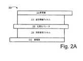
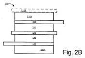
図2Aと図2Bを含む図2はウルトラキャパシタまたは二重層コンデンサで使用できる電極構造体200のそれぞれの断面図を図示する。図2Aで示す電極構造体200の部材は次の順番にアレンジされている。すなわち、第1集電層205、第1活性電極フィルム210、孔質セパレータ220、第2活性電極フィルム230、および第2集電層235である。実施例によっては導電性接着層(図示せず)が電極フィルム210の接着処理に先立って集電層205に成膜される(フィルム230に関しては集電層235)。図2Bで示す二重層210と210Aのフィルムは集電層205に関するものであり、二重層230と230Aのフィルムは集電層235に関するものである。このように二重層コンデンサが形成される。すなわち、両面に炭素フィルムを有した集電層が形成される。さらに孔質セパレータ220Aも含まれる。特にジェリロール型において含まれる。この孔質セパレータ220Aは図示のように上部フィルム210Aに隣接して接着されるか取り付けられ、または底部フィルム230A(図示せず)に隣接して接着されるか取り付けられる。フィルム210と230(および210Aと230A)は図1に関して説明した工程100により得られる活性電極材料の粒体を使用して製造される。電極構造体200を使用した例示的な二重層コンデンサは電解質および電解質を入れる容器、たとえば密封式缶体を含む。電極構造体200はこの容器内に配置され、電解質に浸沈される。多くの実施例では集電層205と237はアルミフォイル製であるが、孔質セパレータ220はセラミック、紙、ポリマー、ポリマー繊維、グラスファイバから選択的に製造でき、電解質溶液は、PCまたはアセトニトリル溶剤等の有機溶液中の1.5Mテトラメチルアンモニウムテトラフルオロボレートを含む。別の電解質例は以下で説明されている。 FIG. 2, including FIGS. 2A and 2B, illustrates a cross-sectional view of an
以下は二重層コンデンサまたはウルトラキャパシタで使用できる電解液の例であるが、これらに限定されない。すなわち、1モル濃度の硫酸ナトリウム(Na2SO4)、1モル濃度の過塩素酸ナトリウム(NaClO4)、1モル濃度の水酸化カリウム(KOH)、1モル濃度の塩化カリウム(KCl)、1モル濃度の過塩素酸(HClO4)、1モル濃度の硫酸(H2SO4)、1モル濃度の塩化マグネシウム(MgCl2)、および1モル濃度のMgCl2/H2O/エタノールである混合水溶液。コンデンサにおいて使用できる非水性非プロトン電解溶剤には、アセトニトリル、ガンマ-ブチロラクトン、ジメトキシエタン、N,N-ジメチルホルムアミド、ヘキサメチルホスホロトリアミド、プロピレンカルボネート、ジメチルカルボネート、テトラヒドロフラン、2-メチルテトラヒドロフラン、ジメチルスルホキシド、ジメチルスルファイト、スルフォラン(テトラ-メチレンスルフォン)、ニトロメタンおよびジオキソランが含まれる。さらに非プロトン系溶剤に使用が可能な電解質塩には、テトラアルキルアンモニウム塩(テトラエチルアンモニウムテトラフルオロボレート((C2H5)4NBF4)、メチルトリエチルアンモニウムテトラフルオロンボレート((C2H5)3CH3NBF4)、テトラブチルアンモニウムテトラフルオロボレート((C4H9)4NBF4)およびテトラエチルアンモニウムヘキサフルオロホスフェート((C2H5)NPF6)、等々)、テトラアルキルホスホニウム塩(テトラエチルホスホニウムテトラフルオロボレート((C2H5)4PBF4)、テトラプロピルホスホニウムテトラフルオロボレート((C3H7)4PBF4)、テトラブチルホスホニウムテトラフルオロボレート((C4H9)4PBF4)、テトラヘキシルホスホニウムテトラフルオロボレート((C6H13)4PBF4)、テトラエチルホスホニウムヘキサフルオロホスフェート((C2H5)4PPF6)およびテトラエチルホスホニウムトリフルオロメチルスルホネート((C2H5)4PCF3SO3)等々)、並びにリチウム塩(リチウムテトラフルオロボレート(LiBF4)、リチウムヘキサフルオロホスフェート(LiPF6)、リチウムトリフルオロメチルスルホネート(LiCF3SO3)、等々)が含まれる。さらに利用できる無溶剤イオン液には、1-エチル-3-メチルイミダゾリウムビス(ペンタフルオロエチルスルホニル)イミド(EMIMBeTi)、1-エチル-3-メチルイミダゾリウムビス(トリフルオロメチルスルホニルイミド(EMIMIm)、EMIIm、EMIBeti、EMIMethide、DMPIIm、DMPIBeti、DMPIMetthide、BMIIm、BMIBeti、BMIMethide、PMPIm、およびBMPImが含まれる。アニオンとして使用する例にはビス(トリフルオロメチルスルホニル)イミド(CF3SO2)2N−、ビス(ペルフルオドエチルスルホニル)イミド(C2F5SO2)2N−、およびトリス(トリフルオロメチルスルホニル)メチド(CF3SO2)3C−が含まれる。カチオンとして使用する例には、EMI(1-エチル-3-メチルイミダゾリウム)、DMPI(1,2-ジメチル-3-プロピルイミダゾリウム、BMI(1-ブチル-3-メチルイミダゾリウム)、PMP(1-N-プロピル-3-メチルピリジニウム、およびBMP(1-N-ブチル-3-メチルピリジニウム)が含まれる。 The following are examples of electrolytes that can be used in double layer capacitors or ultracapacitors, but are not limited thereto. 1 molar sodium sulfate (Na 2 SO 4), 1 molar sodium perchlorate (NaClO 4), 1 molar potassium hydroxide (KOH), 1 molar potassium chloride (KCl), A mixed aqueous solution of chloric acid (HClO4), 1 molar sulfuric acid (H2SO4), 1 molar magnesium chloride (MgCl2), and 1 molar MgCl2 / H2O / ethanol. Non-aqueous aprotic electrolytic solvents that can be used in capacitors include acetonitrile, gamma-butyrolactone, dimethoxyethane, N, N-dimethylformamide, hexamethylphosphorotriamide, propylene carbonate, dimethyl carbonate, tetrahydrofuran, 2-methyltetrahydrofuran, Dimethyl sulfoxide, dimethyl sulfite, sulfolane (tetra-methylene sulfone), nitromethane and dioxolane are included. Furthermore, electrolyte salts that can be used for aprotic solvents include tetraalkylammonium salts (tetraethylammonium tetrafluoroborate ((C2H5) 4NBF4), methyltriethylammonium tetrafluoroborate ((C2H5) 3CH3NBF4)), tetrabutylammonium tetra. Fluoroborate ((C4H9) 4NBF4) and tetraethylammonium hexafluorophosphate ((C2H5) NPF6), etc., tetraalkylphosphonium salts (tetraethylphosphonium tetrafluoroborate ((C2H5) 4PBF4), tetrapropylphosphonium tetrafluoroborate ((C3H7) ) 4PBF4), tetrabutylphosphonium tetrafluoroborate ((C4H9) 4PBF4), tetrahex Ruphosphonium tetrafluoroborate ((C6H13) 4PBF4), tetraethylphosphonium hexafluorophosphate ((C2H5) 4PPF6) and tetraethylphosphonium trifluoromethylsulfonate ((C2H5) 4PCF3SO3), etc.), and lithium salts (lithium tetrafluoroborate (LiBF4)) Lithium hexafluorophosphate (LiPF6), lithium trifluoromethylsulfonate (LiCF3SO3), and the like). Further solvent-free ionic liquids include 1-ethyl-3-methylimidazolium bis (pentafluoroethylsulfonyl) imide (EMIMBeTi), 1-ethyl-3-methylimidazolium bis (trifluoromethylsulfonylimide (EMIMIm) , EMIIm, EMIBeti, EMMethide, DMPIIm, DMPIBeti, DMPIMetide, BMIIm, BMIBeti, BMIMethide, PMPIm, and BMPIm Examples include bis (trifluoromethylsulfonyl) imide (CF3SO2) 2N-, Perfluordoethylsulfonyl) imide (C2F5SO2) 2N-, and tris (trifluoromethylsulfonyl) methide (CF3SO2) 3C- Examples of use as cations include EMI (1-ethyl-3-methylimidazolium), DMPI (1,2-dimethyl-3-propylimidazolium), BMI (1-butyl-3-methylimidazolium), PMP ( 1-N-propyl-3-methylpyridinium, and BMP (1-N-butyl-3-methylpyridinium) are included.
集電層及び/又は孔質セパレータに取り付けられる活性電極フィルムを含む電極製品はウルトラキャパシタまたは二重層コンデンサ及び/又は他の電気エネルギー保存装置に利用できる。 Electrode products comprising an active electrode film attached to a current collecting layer and / or a porous separator can be used in ultracapacitors or double layer capacitors and / or other electrical energy storage devices.
約70から98重量%のミクロ孔質活性炭素粒体と約2から30重量%のメソ孔質活性炭素粒体の活性炭素、あるいは場合によっては約80から98重量%のミクロ孔質活性炭素粒体と約2から20重量%のメソ孔質活性炭素粒体の活性炭素、または約85から95重量%のミクロ孔質活性炭素粒体と約5から15重量%のメソ孔質活性炭素粒体の活性炭素を使用する工程100を利用したいくつかの実施例では、高性能のウルトラキャパシタまたは二重層コンデンサ製品が提供される。このような製品はさらに約10重量%のバインダと、約0.5重量%の導電性炭素のごとき導電性粒体とを含む。 About 70 to 98% by weight of microporous activated carbon particles and about 2 to 30% by weight of mesoporous activated carbon particles, or in some cases about 80 to 98% by weight of microporous activated carbon particles Activated carbon of about 2 to 20% by weight of mesoporous activated carbon particles, or about 85 to 95% by weight of microporous activated carbon particles and about 5 to 15% by weight of mesoporous activated carbon particles. In some embodiments utilizing the
活性電極材料、活性電極材料フィルム、活性電極材料フィルム製電極および活性電極材料電極を使用する二重層コンデンサを製造する本発明の方法を詳細に解説した。この解説は本発明の説明のみを目的とする。本発明の特定の実施例あるいはその特徴部は本発明を制限するものではない。特に本発明は特定の電極材料や材料混合割合に限定されない。本発明は二重層コンデンサに使用される電極に限定されない。ここで解説する特定の特徴は本発明の精神とスコープを逸脱せずに他の形態においても利用が可能である。多くの追加的改良は本発明の開示内であり、本発明の特徴の一部が採用されずとも本発明の実施は可能である。よって解説された実施例は本発明の範囲を定義するものではなく、本発明の真の範囲は「請求の範囲」により定義されたものである。 The method of the present invention for producing an active electrode material, an active electrode material film, an electrode made of active electrode material film and a double layer capacitor using the active electrode material electrode has been described in detail. This discussion is for illustrative purposes only. Particular embodiments of the present invention or its features are not intended to limit the invention. In particular, the present invention is not limited to a specific electrode material or material mixing ratio. The present invention is not limited to electrodes used in double layer capacitors. Certain features described herein may be utilized in other forms without departing from the spirit and scope of the present invention. Many additional improvements are within the disclosure of the invention, and the invention may be practiced without some of the features of the invention being employed. Thus, the described embodiments do not define the scope of the invention, but the true scope of the invention is defined by the appended claims.
Claims (31)
Translated fromJapanese第1集電層と、活性電極材料製の第1フィルムとを含んだ第1電極を含んでおり、該第1フィルムは第1面と第2面とを有しており、前記第1集電層は前記第1フィルムの前記第1面に取り付けられており、前記第1フィルムは、全活性炭素重量に対して70重量%から98重量%のミクロ孔質活性炭素粒体と、2重量%から30重量%のメソ孔質活性炭素粒体とを有した活性炭素を含んでおり、本コンデンサは、
第2集電層と、活性電極材料製の第2フィルムとを含んだ第2電極をさらに含んでおり
、該第2フィルムは第3面と第4面とを有しており、前記第2集電層は前記第2フィルムの前記第3面に取り付けられており、本コンデンサは、
前記第1フィルムの前記第2面と前記第2フィルムの前記第4面との間に配置される孔質セパレータと、容器と、電解質とをさらに含んでおり、
前記第1電極と、前記第2電極と、前記孔質セパレータと、前記電解質とは前記容器内に収納されており、
前記第1フィルムは前記電解質内に少なくともその一部が浸沈しており、前記第2フィルムは該電解質内に少なくともその一部が浸沈しており、前記孔質セパレータは該電解質内に少なくともその一部が浸沈していることを特徴とする二重層コンデンサ。An electrochemical double layer capacitor,
A first electrode including a first current collecting layer and a first film made of an active electrode material, the first film having a first surface and a second surface; An electrical layer is attached to the first surface of the first film, the first film comprising 70% to 98% by weight of microporous activated carbon granules and 2% by weight relative to the total activated carbon weight. Containing 30% to 30% by weight of mesoporous activated carbon particles,
A second electrode including a second current collecting layer and a second film made of an active electrode material, the second film having a third surface and a fourth surface; The current collecting layer is attached to the third surface of the second film, and the capacitor is
A porous separator disposed between the second surface of the first film and the fourth surface of the second film, a container, and an electrolyte;
The first electrode, the second electrode, the porous separator, and the electrolyte are housed in the container;
The first film is at least partially immersed in the electrolyte, the second film is at least partially immersed in the electrolyte, and the porous separator is at least partially immersed in the electrolyte. double layer capacitor partthereof, characterized inthat it Hita沈.
前記電極は、集電層と、前記集電層に取り付けられた活性電極材料の乾燥フィルムとを、備え、The electrode comprises a current collecting layer and a dry film of an active electrode material attached to the current collecting layer,
前記活性電極材料は、全活性炭素重量に対して70重量%から98重量%のミクロ孔質活性炭素粒体と、全活性炭素重量に対して2重量%から30重量%のメソ孔質活性炭素粒体と、乾燥バインダと、を含むことを特徴とするエネルギー保存装置。The active electrode material comprises 70% to 98% by weight of microporous activated carbon particles based on the total activated carbon weight, and 2% to 30% by weight mesoporous activated carbon based on the total activated carbon weight. An energy storage device comprising a granule and a dry binder.
Applications Claiming Priority (3)
| Application Number | Priority Date | Filing Date | Title |
|---|---|---|---|
| US85245906P | 2006-10-17 | 2006-10-17 | |
| US60/852,459 | 2006-10-17 | ||
| PCT/US2007/081698WO2008049037A2 (en) | 2006-10-17 | 2007-10-17 | Electrode for energy storage device |
Publications (2)
| Publication Number | Publication Date |
|---|---|
| JP2010507264A JP2010507264A (en) | 2010-03-04 |
| JP5276001B2true JP5276001B2 (en) | 2013-08-28 |
Family
ID=39314826
Family Applications (1)
| Application Number | Title | Priority Date | Filing Date |
|---|---|---|---|
| JP2009533513AActiveJP5276001B2 (en) | 2006-10-17 | 2007-10-17 | Electrode for energy storage device |
Country Status (6)
| Country | Link |
|---|---|
| US (5) | US20080089006A1 (en) |
| EP (2) | EP2082408A4 (en) |
| JP (1) | JP5276001B2 (en) |
| KR (2) | KR101423725B1 (en) |
| CN (1) | CN101595541B (en) |
| WO (2) | WO2008049040A2 (en) |
Families Citing this family (83)
| Publication number | Priority date | Publication date | Assignee | Title |
|---|---|---|---|---|
| US7352558B2 (en) | 2003-07-09 | 2008-04-01 | Maxwell Technologies, Inc. | Dry particle based capacitor and methods of making same |
| US7791860B2 (en) | 2003-07-09 | 2010-09-07 | Maxwell Technologies, Inc. | Particle based electrodes and methods of making same |
| US7920371B2 (en) | 2003-09-12 | 2011-04-05 | Maxwell Technologies, Inc. | Electrical energy storage devices with separator between electrodes and methods for fabricating the devices |
| US7090946B2 (en) | 2004-02-19 | 2006-08-15 | Maxwell Technologies, Inc. | Composite electrode and method for fabricating same |
| US7440258B2 (en) | 2005-03-14 | 2008-10-21 | Maxwell Technologies, Inc. | Thermal interconnects for coupling energy storage devices |
| WO2008049040A2 (en)* | 2006-10-17 | 2008-04-24 | Maxwell Technologies, Inc. | Electrode for energy storage device |
| JP4994205B2 (en)* | 2007-12-06 | 2012-08-08 | 三菱電機株式会社 | Electric double layer capacitor and manufacturing method thereof |
| JP4524316B2 (en)* | 2008-01-30 | 2010-08-18 | 株式会社沖データ | Image processing apparatus and image processing system |
| US20100008020A1 (en)* | 2008-07-09 | 2010-01-14 | Adrian Schneuwly | Electrode device |
| WO2010009469A2 (en)* | 2008-07-18 | 2010-01-21 | Peckerar Martin C | Thin flexible rechargeable electrochemical energy cell and method of fabrication |
| US8318356B2 (en) | 2008-12-15 | 2012-11-27 | Corning Incorporated | Activated carbon materials for high energy density ultracapacitors |
| US7931985B1 (en)* | 2010-11-08 | 2011-04-26 | International Battery, Inc. | Water soluble polymer binder for lithium ion battery |
| US8076026B2 (en)* | 2010-02-05 | 2011-12-13 | International Battery, Inc. | Rechargeable battery using an aqueous binder |
| US20110143206A1 (en)* | 2010-07-14 | 2011-06-16 | International Battery, Inc. | Electrode for rechargeable batteries using aqueous binder solution for li-ion batteries |
| US8102642B2 (en)* | 2010-08-06 | 2012-01-24 | International Battery, Inc. | Large format ultracapacitors and method of assembly |
| EP2614547B1 (en) | 2010-09-09 | 2020-07-08 | California Institute of Technology | Three-dimensional electrode array and method of making it |
| US8765297B2 (en) | 2011-01-04 | 2014-07-01 | Exide Technologies | Advanced graphite additive for enhanced cycle-life of lead-acid batteries |
| DE102011011154A1 (en)* | 2011-02-14 | 2012-08-16 | Li-Tec Battery Gmbh | Process for the production of electrodes |
| DE102011011155A1 (en)* | 2011-02-14 | 2012-08-16 | Li-Tec Battery Gmbh | Process for the production of electrodes |
| US9379368B2 (en) | 2011-07-11 | 2016-06-28 | California Institute Of Technology | Electrochemical systems with electronically conductive layers |
| EP2732487A4 (en) | 2011-07-11 | 2015-04-08 | California Inst Of Techn | NEW SEPARATORS FOR ELECTROCHEMICAL SYSTEMS |
| JP2013020820A (en)* | 2011-07-12 | 2013-01-31 | Hitachi Ltd | Electrode for lithium secondary battery and secondary battery using the same |
| US10240052B2 (en)* | 2011-09-30 | 2019-03-26 | Ppg Industries Ohio, Inc. | Supercapacitor electrodes including graphenic carbon particles |
| US10294375B2 (en) | 2011-09-30 | 2019-05-21 | Ppg Industries Ohio, Inc. | Electrically conductive coatings containing graphenic carbon particles |
| US12421118B2 (en) | 2011-09-30 | 2025-09-23 | Ppg Industries Ohio, Inc. | Graphenic carbon particles |
| WO2013148051A1 (en)* | 2012-03-30 | 2013-10-03 | Linda Zhong | Electrode for energy storage devices and method for making same |
| US11011737B2 (en) | 2012-05-16 | 2021-05-18 | Eskra Technical Products, Inc. | System and method of fabricating an electrochemical device |
| US11050121B2 (en)* | 2012-05-16 | 2021-06-29 | Eskra Technical Products, Inc. | System and method for fabricating an electrode with separator |
| US20130323583A1 (en)* | 2012-05-31 | 2013-12-05 | Dragonfly Energy, LLC | Processes for the manufacture of conductive particle films for lithium ion batteries |
| US11283104B2 (en)* | 2012-06-01 | 2022-03-22 | Global Graphene Group, Inc. | Rechargeable dual electroplating cell |
| KR101674843B1 (en)* | 2012-09-20 | 2016-11-09 | 아사히 가세이 가부시키가이샤 | Lithium ion capacitor |
| CN108010739B (en) | 2012-10-08 | 2020-11-10 | 麦克斯威科技公司 | Electrolyte for three-volt super capacitor |
| US10014520B2 (en) | 2012-10-31 | 2018-07-03 | Exide Technologies Gmbh | Composition that enhances deep cycle performance of valve-regulated lead-acid batteries filled with gel electrolyte |
| KR101973407B1 (en)* | 2012-12-27 | 2019-04-29 | 삼성전기주식회사 | Apparatus for storing electric energy and method for manufacturing the same |
| US20160226118A1 (en)* | 2013-01-17 | 2016-08-04 | Leon L. Shaw | Sodium-based hybrid flow batteries with ultrahigh energy densities |
| US9236599B2 (en) | 2013-02-28 | 2016-01-12 | Linda Zhong | Low cost high performance electrode for energy storage devices and systems and method of making same |
| CN104396043B (en) | 2013-04-29 | 2016-10-19 | 株式会社Lg化学 | Package for cable-type secondary battery and cable-type secondary battery including same |
| WO2014182064A1 (en) | 2013-05-07 | 2014-11-13 | 주식회사 엘지화학 | Electrode for secondary battery, method for manufacturing same, and secondary battery and cable-type secondary battery including same |
| WO2014182056A1 (en) | 2013-05-07 | 2014-11-13 | 주식회사 엘지화학 | Cable-type secondary battery and method for manufacturing same |
| KR101465164B1 (en) | 2013-05-07 | 2014-11-25 | 주식회사 엘지화학 | Cable-Type Secondary Battery |
| JP6050483B2 (en) | 2013-05-07 | 2016-12-21 | エルジー・ケム・リミテッド | Cable type secondary battery |
| JP6240176B2 (en)* | 2013-05-07 | 2017-11-29 | エルジー・ケム・リミテッド | Secondary battery electrode, manufacturing method thereof, secondary battery including the same, and cable-type secondary battery |
| KR101470556B1 (en) | 2013-05-07 | 2014-12-10 | 주식회사 엘지화학 | Electrode for a secondary battery, preparation method thereof, secondary battery and cable-type secondary battery including the same |
| WO2014182063A1 (en) | 2013-05-07 | 2014-11-13 | 주식회사 엘지화학 | Electrode for secondary battery, method for manufacturing same, and secondary battery and cable-type secondary battery comprising same |
| US10121607B2 (en)* | 2013-08-22 | 2018-11-06 | Corning Incorporated | Ceramic separator for ultracapacitors |
| KR102040192B1 (en) | 2013-10-18 | 2019-11-04 | 삼성에스디아이 주식회사 | Coated separator and electrochemical device including the same |
| US9607776B2 (en)* | 2013-10-24 | 2017-03-28 | Corning Incorporated | Ultracapacitor with improved aging performance |
| US10714724B2 (en) | 2013-11-18 | 2020-07-14 | California Institute Of Technology | Membranes for electrochemical cells |
| US9991492B2 (en) | 2013-11-18 | 2018-06-05 | California Institute Of Technology | Separator enclosures for electrodes and electrochemical cells |
| CN106415892A (en) | 2014-06-03 | 2017-02-15 | 阿科玛股份有限公司 | Fabrication of solvent-free electrodes |
| EP3213361B1 (en) | 2014-10-27 | 2020-10-21 | Dragonfly Energy Corp. | Processes for the manufacture of conductive particle films for lithium ion batteries and lithium ion batteries |
| TWI584317B (en)* | 2014-10-31 | 2017-05-21 | 片片堅俄亥俄州工業公司 | Electrode coating and supercapacitor electrodes including graphenic carbon particles and supercapacitor comprising the same |
| US10037850B2 (en)* | 2014-12-18 | 2018-07-31 | 3M Innovative Properties Company | Multilayer film capacitor |
| PL3800714T3 (en)* | 2014-12-26 | 2021-12-20 | Zeon Corporation | Binder composition for non-aqueous secondary battery positive electrode, composition for non-aqueous secondary battery positive electrode, positive electrode for non-aqueous secondary battery, and non-aqueous secondary battery, and methods for producing composition for non-aqueous secondary battery positive electrode, positive electrode for non-aqueous secondary battery, and non-aqueous secondary battery |
| KR102625359B1 (en) | 2015-02-09 | 2024-01-17 | 알케마 인코포레이티드 | Particulate polymer binder composite |
| US10833324B2 (en)* | 2015-08-25 | 2020-11-10 | Licap Technologies, Inc. | Electrodes with controlled amount of lithium attached and method of making same |
| WO2017096258A1 (en) | 2015-12-02 | 2017-06-08 | California Institute Of Technology | Three-dimensional ion transport networks and current collectors for electrochemical cells |
| KR102495794B1 (en) | 2016-05-20 | 2023-02-06 | 교세라 에이브이엑스 컴포넌츠 코포레이션 | Electrode configuration for an ultracapacitor |
| WO2017201183A1 (en) | 2016-05-20 | 2017-11-23 | Avx Corporation | Ultracapacitor for use at high temperatures |
| JP7061971B2 (en) | 2016-05-20 | 2022-05-02 | キョーセラ・エイブイエックス・コンポーネンツ・コーポレーション | Multicell ultracapacitor |
| CN109155206A (en) | 2016-05-20 | 2019-01-04 | 阿维科斯公司 | Nonaqueous Electrolytes for Supercapacitors |
| KR102063059B1 (en)* | 2016-08-17 | 2020-01-07 | 주식회사 엘지화학 | Method for manufacturing conductive product |
| KR102126679B1 (en)* | 2016-08-18 | 2020-06-25 | 주식회사 엘지화학 | Method for manufacturing conductor with network structure |
| US11830672B2 (en) | 2016-11-23 | 2023-11-28 | KYOCERA AVX Components Corporation | Ultracapacitor for use in a solder reflow process |
| GB2561253B (en)* | 2017-04-07 | 2022-10-12 | Zapgo Ltd | Self-supporting carbon electrode |
| US11532441B2 (en)* | 2017-06-30 | 2022-12-20 | KYOCERA AVX Components Corporation | Electrode assembly for an ultracapacitor |
| KR102076254B1 (en)* | 2017-10-19 | 2020-02-12 | 한국과학기술연구원 | Composite comprising polymer and hybrid carbon fillers and process of preparing the same |
| US20190237748A1 (en) | 2017-11-22 | 2019-08-01 | Maxwell Technologies, Inc. | Compositions and methods for energy storage devices having improved performance |
| EP3776601A4 (en)* | 2018-04-13 | 2021-12-22 | Navitas Systems LLC | Compositions and methods for electrode fabrication |
| US11443902B2 (en)* | 2018-10-04 | 2022-09-13 | Pacesetter, Inc. | Hybrid anode and electrolytic capacitor |
| US11367864B2 (en)* | 2018-11-08 | 2022-06-21 | Tesla, Inc. | Intermittently coated dry electrode for energy storage device and method of manufacturing the same |
| US11524304B2 (en)* | 2018-12-21 | 2022-12-13 | Robert Bosch Gmbh | Electrostatic charging air cleaning device and collection electrode |
| CN109755019B (en)* | 2019-01-10 | 2020-12-04 | 阜阳颍知网络信息科技有限公司 | A low temperature resistant vegetable oil based impregnating agent for capacitors |
| CN119725373A (en)* | 2019-01-15 | 2025-03-28 | 麦斯韦尔技术股份有限公司 | Compositions and methods for pre-lithiation energy storage devices |
| US11508956B2 (en) | 2020-09-08 | 2022-11-22 | Licap Technologies, Inc. | Dry electrode manufacture with lubricated active material mixture |
| JP7670312B2 (en)* | 2021-03-08 | 2025-04-30 | 国立大学法人秋田大学 | Active materials for electric double layer capacitors |
| US12327856B2 (en) | 2021-10-01 | 2025-06-10 | Licap Technologies, Inc. | Dry electrode manufacture for solid state energy storage devices |
| EP4199157A4 (en)* | 2021-10-29 | 2023-12-27 | Contemporary Amperex Technology Co., Limited | Battery current collector and preparation method therefor, secondary battery, battery module, battery packet, and electric device |
| DE102022105852A1 (en)* | 2022-03-14 | 2023-09-14 | Bayerische Motoren Werke Aktiengesellschaft | Method for producing an electrode for an electrochemical cell, composite electrode and electrochemical cell |
| EP4391097A1 (en) | 2022-12-22 | 2024-06-26 | OQ Chemicals GmbH | Thick electrode film forming method for secondary alkali ion energy storage devices |
| KR102754761B1 (en)* | 2023-01-25 | 2025-01-21 | 주식회사 코스모스랩 | Electrode for energy storage device and zinc-bromide battery comprising the same |
| WO2024177583A1 (en)* | 2023-02-21 | 2024-08-29 | Bohas Stratejik Danişmanlik Ve Diş Ticaret A.Ş. | Magnesium battery |
| WO2024176955A1 (en)* | 2023-02-21 | 2024-08-29 | 三井化学株式会社 | Electrode binder, electrode mixture layer, material for forming electrode mixture layer, method for manufacturing electrode mixture layer, electrode, and lithium-ion secondary battery |
Family Cites Families (106)
| Publication number | Priority date | Publication date | Assignee | Title |
|---|---|---|---|---|
| US1752963A (en)* | 1928-04-30 | 1930-04-01 | Pettinelli Parisino | Grid for chemical storage batteries |
| CA1081320A (en)* | 1977-07-14 | 1980-07-08 | Moli Energy Ltd. | Battery with improved dichalcogenide cathode |
| US4327400A (en)* | 1979-01-10 | 1982-04-27 | Matsushita Electric Industrial Co., Ltd. | Electric double layer capacitor |
| US4320184A (en)* | 1981-01-19 | 1982-03-16 | Mpd Technology Corporation | Production of a cell electrode system |
| DE3838329A1 (en)* | 1987-11-11 | 1989-05-24 | Ricoh Kk | Negative electrode for a secondary battery |
| US4925752A (en)* | 1989-03-03 | 1990-05-15 | Fauteux Denis G | Solid state electrochemical cell having porous cathode current collector |
| US5415768A (en)* | 1990-04-23 | 1995-05-16 | Andelman; Marc D. | Flow-through capacitor |
| US5620597A (en)* | 1990-04-23 | 1997-04-15 | Andelman; Marc D. | Non-fouling flow-through capacitor |
| US5192432A (en)* | 1990-04-23 | 1993-03-09 | Andelman Marc D | Flow-through capacitor |
| JP2756357B2 (en) | 1990-10-12 | 1998-05-25 | 塩野義製薬株式会社 | Method and apparatus for producing agar-like base material small pieces |
| JPH04359777A (en) | 1991-06-06 | 1992-12-14 | Hitachi Ltd | refrigerator |
| JPH05148670A (en) | 1991-11-26 | 1993-06-15 | Saga Pref Gov | Corrosion inhibitor for metal |
| JPH07161588A (en)* | 1993-12-06 | 1995-06-23 | Nisshinbo Ind Inc | Polarizing electrode for electric double-layer capacitor, its manufacture and electric double-layer capacitor using polarizing electrode described above |
| JPH07130370A (en)* | 1993-10-29 | 1995-05-19 | Matsushita Electric Ind Co Ltd | Coated electrode and method for manufacturing the same |
| JP2993343B2 (en) | 1993-12-28 | 1999-12-20 | 日本電気株式会社 | Polarizing electrode and method of manufacturing the same |
| US5862035A (en)* | 1994-10-07 | 1999-01-19 | Maxwell Energy Products, Inc. | Multi-electrode double layer capacitor having single electrolyte seal and aluminum-impregnated carbon cloth electrodes |
| US5953204A (en)* | 1994-12-27 | 1999-09-14 | Asahi Glass Company Ltd. | Electric double layer capacitor |
| US5849430A (en)* | 1995-05-31 | 1998-12-15 | Samsung Display Devices Co., Ltd. | Structure of an electrode of a secondary battery |
| JPH097603A (en)* | 1995-06-22 | 1997-01-10 | Matsushita Electric Ind Co Ltd | Non-sintered nickel electrode and its manufacturing method |
| JP3481797B2 (en)* | 1996-10-03 | 2003-12-22 | 片山特殊工業株式会社 | Method for manufacturing battery electrode substrate and battery electrode substrate |
| WO1998033227A1 (en) | 1997-01-27 | 1998-07-30 | Kanebo Limited | Organic electrolytic battery |
| US6022436A (en)* | 1997-03-07 | 2000-02-08 | Koslow Technologies Corporation | Electrode manufacturing process and flow-through capacitor produced therefrom |
| JP3429428B2 (en)* | 1997-04-08 | 2003-07-22 | 本田技研工業株式会社 | Current collector for energy storage device |
| JPH10326628A (en)* | 1997-05-26 | 1998-12-08 | Mitsubishi Electric Corp | Battery and manufacturing method thereof |
| US6127474A (en) | 1997-08-27 | 2000-10-03 | Andelman; Marc D. | Strengthened conductive polymer stabilized electrode composition and method of preparing |
| EP0917166B1 (en)* | 1997-09-22 | 2007-08-01 | Japan Gore-Tex, Inc. | Electric double layer capacitor and process for manufacturing the same |
| JPH11191418A (en)* | 1997-10-22 | 1999-07-13 | Nippon Foil Mfg Co Ltd | Plate current collector and its manufacture |
| JPH11135369A (en)* | 1997-10-28 | 1999-05-21 | Nec Corp | Electrical double layer capacitor |
| CA2338717C (en) | 1998-07-27 | 2009-06-30 | Nobuo Ando | Organic electrolytic cell |
| JP3241325B2 (en) | 1998-07-31 | 2001-12-25 | 日本電気株式会社 | Electric double layer capacitor |
| EP1115130A4 (en)* | 1998-08-25 | 2007-05-02 | Fuji Heavy Ind Ltd | ELECTRODE MATERIAL AND MANUFACTURING METHOD |
| US6201685B1 (en) | 1998-10-05 | 2001-03-13 | General Electric Company | Ultracapacitor current collector |
| US6198623B1 (en)* | 1999-01-29 | 2001-03-06 | Telcordia Technologies, Inc. | Carbon fabric supercapacitor structure |
| JP2000286165A (en)* | 1999-03-30 | 2000-10-13 | Nec Corp | Electric double-layer capacitor and manufacture thereof |
| JP2001035499A (en)* | 1999-05-19 | 2001-02-09 | Toshiba Battery Co Ltd | Electricity collecting base board for electrode of alkaline secondary battery, electrode using same, and alkaline secondary battery incorporating the electrode |
| US6296746B1 (en) | 1999-07-01 | 2001-10-02 | Squirrel Holdings Ltd. | Bipolar electrode for electrochemical redox reactions |
| JP2001044082A (en) | 1999-07-29 | 2001-02-16 | Asahi Glass Co Ltd | Method for manufacturing electric double layer capacitor |
| US6456484B1 (en) | 1999-08-23 | 2002-09-24 | Honda Giken Kogyo Kabushiki Kaisha | Electric double layer capacitor |
| JP2001143973A (en) | 1999-11-15 | 2001-05-25 | Asahi Glass Co Ltd | High-density electrode mainly composed of spherical activated carbon and electric double layer capacitor using the same |
| JP4475722B2 (en)* | 2000-02-21 | 2010-06-09 | 古河電池株式会社 | ELECTRODE FOR LITHIUM BATTERY, METHOD FOR PRODUCING THE SAME, AND BATTERY USING THE SAME |
| WO2001065624A1 (en)* | 2000-02-29 | 2001-09-07 | Koninklijke Philips Electronics N.V. | Lithium battery |
| JP2001250742A (en) | 2000-03-07 | 2001-09-14 | Nec Corp | Electric double layer capacitor and its manufacturing method |
| US6627252B1 (en) | 2000-05-12 | 2003-09-30 | Maxwell Electronic Components, Inc. | Electrochemical double layer capacitor having carbon powder electrodes |
| US6631074B2 (en) | 2000-05-12 | 2003-10-07 | Maxwell Technologies, Inc. | Electrochemical double layer capacitor having carbon powder electrodes |
| TW523767B (en) | 2000-09-11 | 2003-03-11 | Nec Tokin Corp | Electrical double layer capacitor |
| JP2003003078A (en)* | 2000-09-19 | 2003-01-08 | Nisshinbo Ind Inc | Ion conductive composition, gel electrolyte, non-aqueous electrolyte battery, and electric double layer capacitor |
| FR2817387B1 (en) | 2000-11-27 | 2003-03-21 | Ceca Sa | ENERGY STORAGE CELLS WITH HIGH ELECTRICAL CHEMICAL DOUBLE LAYER AND HIGH POWER DENSITY |
| US7110242B2 (en)* | 2001-02-26 | 2006-09-19 | C And T Company, Inc. | Electrode for electric double layer capacitor and method of fabrication thereof |
| JP4836351B2 (en)* | 2001-05-17 | 2011-12-14 | パナソニック株式会社 | Electrode plate for alkaline storage battery and alkaline storage battery using the same |
| AU2002244957B2 (en) | 2001-06-29 | 2005-07-21 | Subaru Corporation | Organic electrolyte capacitor |
| US20060159999A1 (en)* | 2001-07-23 | 2006-07-20 | Kejha Joseph B | Method of automated prismatic electrochemical cells production and method of the cell assembly and construction |
| JP2003045760A (en)* | 2001-07-30 | 2003-02-14 | Asahi Glass Co Ltd | Multilayer electric double layer capacitor module |
| JP2003054524A (en) | 2001-08-10 | 2003-02-26 | Nireco Corp | Heat resistant label |
| US20030059674A1 (en)* | 2001-09-27 | 2003-03-27 | Mann Gamdur Singh | Electrode having expanded surface area and inner chamber encapsulating a highly reactive material for use in a liquid electrolyte battery |
| US20030161781A1 (en)* | 2001-10-01 | 2003-08-28 | Israel Cabasso | Novel carbon materials and carbon/carbon composites based on modified poly (phenylene ether) for energy production and storage devices, and methods of making them |
| DE10203143A1 (en)* | 2002-01-28 | 2003-08-07 | Epcos Ag | Electrodes, their manufacture and capacitors with the electrodes |
| US6500770B1 (en) | 2002-04-22 | 2002-12-31 | Taiwan Semiconductor Manufacturing Company, Ltd | Method for forming a multi-layer protective coating over porous low-k material |
| JP2003341526A (en) | 2002-05-24 | 2003-12-03 | Iseki & Co Ltd | Steering handle mounting structure |
| JP3884768B2 (en)* | 2002-06-21 | 2007-02-21 | 日立マクセル株式会社 | Electrode for electrochemical device and battery using the same |
| US7061749B2 (en)* | 2002-07-01 | 2006-06-13 | Georgia Tech Research Corporation | Supercapacitor having electrode material comprising single-wall carbon nanotubes and process for making the same |
| JP4833504B2 (en)* | 2002-11-22 | 2011-12-07 | 日立マクセルエナジー株式会社 | Electrochemical capacitor and hybrid power supply comprising the same |
| KR100506731B1 (en) | 2002-12-24 | 2005-08-08 | 삼성전기주식회사 | Low temperature sinterable dielectric composition, multilayer ceramic capacitor, ceramic electronic device |
| US20060115723A1 (en) | 2002-12-25 | 2006-06-01 | Fuji Jukogyo Kabushiki Kaisha | Storage device |
| JPWO2004059672A1 (en) | 2002-12-26 | 2006-05-11 | 富士重工業株式会社 | Power storage device and method for manufacturing power storage device |
| TWI288495B (en)* | 2003-03-27 | 2007-10-11 | Nec Tokin Corp | Electrode and electrochemical cell therewith |
| KR100816404B1 (en)* | 2003-03-31 | 2008-03-27 | 후지 주코교 카부시키카이샤 | Organic electrolyte capacitor |
| US7006346B2 (en)* | 2003-04-09 | 2006-02-28 | C And T Company, Inc. | Positive electrode of an electric double layer capacitor |
| US6842328B2 (en)* | 2003-05-30 | 2005-01-11 | Joachim Hossick Schott | Capacitor and method for producing a capacitor |
| US20040258992A1 (en)* | 2003-06-19 | 2004-12-23 | Park Dong Pil | Negative plate for nickel/metal hydride secondary battery and fabrication method thereof |
| KR20120094145A (en)* | 2003-07-28 | 2012-08-23 | 쇼와 덴코 가부시키가이샤 | High density electrode and battery using the electrode |
| US7102877B2 (en)* | 2003-09-12 | 2006-09-05 | Maxwell Technologies, Inc. | Electrode impregnation and bonding |
| EP1670008B1 (en) | 2003-09-30 | 2012-09-12 | Fuji Jukogyo Kabushiki Kaisha | Organic electrolytic capacitor |
| JP2005104676A (en) | 2003-09-30 | 2005-04-21 | Canon Inc | Sheet processing device |
| JP2005104701A (en) | 2003-10-01 | 2005-04-21 | Canon Sales Co Inc | Transportation business management device, system, and program |
| JP2005104709A (en) | 2003-10-02 | 2005-04-21 | Hokuto Corp | Workpiece conveyance device |
| JP4262046B2 (en) | 2003-10-20 | 2009-05-13 | 甫 羽田野 | Sound inspection system |
| JP2005128714A (en) | 2003-10-22 | 2005-05-19 | Toshiba Corp | Failure response support system, service center system, and failure response support method |
| JP2005125707A (en) | 2003-10-27 | 2005-05-19 | Canon Inc | PRINT SYSTEM, PRINT NUMBER MANAGEMENT DEVICE, PRINT NUMBER MANAGEMENT METHOD, PROGRAM, AND STORAGE MEDIUM |
| JP4391198B2 (en)* | 2003-10-31 | 2009-12-24 | オルガノ株式会社 | Activated carbon precursor, activated carbon, method for producing activated carbon, and polarizable electrode for electric double layer capacitor |
| JP2005158816A (en)* | 2003-11-20 | 2005-06-16 | Tdk Corp | Electrochemical device and manufacturing method thereof |
| JP4608871B2 (en)* | 2003-11-20 | 2011-01-12 | Tdk株式会社 | Electrode for electrochemical capacitor and manufacturing method thereof, and electrochemical capacitor and manufacturing method thereof |
| JP4713829B2 (en) | 2003-11-28 | 2011-06-29 | 株式会社平和 | Game machine |
| JP2005196723A (en) | 2003-12-09 | 2005-07-21 | Oki Electric Ind Co Ltd | Cash processing device and system |
| JP4276063B2 (en)* | 2003-12-26 | 2009-06-10 | Tdk株式会社 | Electrode capacitor electrode manufacturing method and electrochemical capacitor manufacturing method |
| JP4235911B2 (en) | 2004-03-02 | 2009-03-11 | ノーリツ鋼機株式会社 | Transport unit support structure |
| JP2005249763A (en) | 2004-03-02 | 2005-09-15 | Takahiro Kato | Measure hook mounting device |
| JP3866725B2 (en) | 2004-03-03 | 2007-01-10 | 正隆 中沢 | Manufacturing method of plastic holey fiber |
| JP4595352B2 (en) | 2004-03-04 | 2010-12-08 | 株式会社豊田中央研究所 | Aqueous electrolyte lithium secondary battery |
| US20050233203A1 (en)* | 2004-03-15 | 2005-10-20 | Hampden-Smith Mark J | Modified carbon products, their use in fluid/gas diffusion layers and similar devices and methods relating to the same |
| JP2005286170A (en) | 2004-03-30 | 2005-10-13 | Daido Metal Co Ltd | Manufacturing method of activated carbon for electric double-layer capacitor electrode |
| JP2005302342A (en) | 2004-04-07 | 2005-10-27 | Seiko Epson Corp | Static eliminator |
| JP2005329455A (en) | 2004-05-18 | 2005-12-02 | Keisuke Toda | Brazing furnace for making chain ring |
| CN1753116B (en)* | 2004-09-20 | 2010-04-28 | 中国科学院电工研究所 | A carbon-based porous electrode film for supercapacitors and its preparation method |
| US7553341B2 (en)* | 2004-11-24 | 2009-06-30 | The Regents Of The University Of California | High power density supercapacitors with carbon nanotube electrodes |
| US7147674B1 (en) | 2005-03-23 | 2006-12-12 | Maxwell Technologies, Inc. | Pretreated porous electrode and method for manufacturing same |
| JP4670430B2 (en)* | 2005-03-30 | 2011-04-13 | Tdk株式会社 | Electrochemical devices |
| US7733629B2 (en) | 2005-03-31 | 2010-06-08 | Fuji Jukogyo Kabushiki Kaisha | Lithium ion capacitor |
| JP4731967B2 (en) | 2005-03-31 | 2011-07-27 | 富士重工業株式会社 | Lithium ion capacitor |
| KR101161721B1 (en) | 2005-03-31 | 2012-07-03 | 후지 주코교 카부시키카이샤 | Lithium ion capacitor |
| CN101167208B (en)* | 2005-04-26 | 2012-09-19 | 富士重工业株式会社 | Negative electrode active material for electricity storage device |
| US8313723B2 (en)* | 2005-08-25 | 2012-11-20 | Nanocarbons Llc | Activated carbon fibers, methods of their preparation, and devices comprising activated carbon fibers |
| US7548489B1 (en)* | 2006-07-05 | 2009-06-16 | The United States Of America As Represented By The Secretary Of The Navy | Method for designing a resonant acoustic projector |
| US20080014504A1 (en)* | 2006-07-14 | 2008-01-17 | Adrian Schneuwly | Method of making and article of manufacture for an energy storage electrode apparatus |
| US7580243B2 (en)* | 2006-07-14 | 2009-08-25 | Maxwell Technologies, Inc. | Method of making and article of manufacture for an ultracapacitor electrode apparatus |
| WO2008049040A2 (en)* | 2006-10-17 | 2008-04-24 | Maxwell Technologies, Inc. | Electrode for energy storage device |
| US8021533B2 (en)* | 2007-11-20 | 2011-09-20 | GM Global Technology Operations LLC | Preparation of hydrogen storage materials |
- 2007
- 2007-10-17WOPCT/US2007/081703patent/WO2008049040A2/enactiveApplication Filing
- 2007-10-17CNCN2007800388797Apatent/CN101595541B/enactiveActive
- 2007-10-17USUS11/874,188patent/US20080089006A1/ennot_activeAbandoned
- 2007-10-17WOPCT/US2007/081698patent/WO2008049037A2/enactiveApplication Filing
- 2007-10-17KRKR1020097009906Apatent/KR101423725B1/enactiveActive
- 2007-10-17EPEP07854145.5Apatent/EP2082408A4/ennot_activeWithdrawn
- 2007-10-17USUS11/874,172patent/US20080089013A1/ennot_activeAbandoned
- 2007-10-17EPEP07854143.0Apatent/EP2082407B1/enactiveActive
- 2007-10-17KRKR1020097010063Apatent/KR20090081398A/ennot_activeCeased
- 2007-10-17JPJP2009533513Apatent/JP5276001B2/enactiveActive
- 2007-10-17USUS12/445,294patent/US20100110612A1/ennot_activeAbandoned
- 2007-10-17USUS12/445,295patent/US8279580B2/enactiveActive
- 2012
- 2012-08-31USUS13/601,567patent/US8591601B2/enactiveActive
Also Published As
| Publication number | Publication date |
|---|---|
| EP2082408A4 (en) | 2013-07-03 |
| CN101595541B (en) | 2012-02-15 |
| CN101595541A (en) | 2009-12-02 |
| JP2010507264A (en) | 2010-03-04 |
| US20130056138A1 (en) | 2013-03-07 |
| US20080089013A1 (en) | 2008-04-17 |
| WO2008049037A2 (en) | 2008-04-24 |
| US20100033898A1 (en) | 2010-02-11 |
| EP2082407B1 (en) | 2015-11-18 |
| EP2082407A4 (en) | 2013-07-03 |
| US20080089006A1 (en) | 2008-04-17 |
| US8591601B2 (en) | 2013-11-26 |
| US8279580B2 (en) | 2012-10-02 |
| KR101423725B1 (en) | 2014-08-06 |
| WO2008049040A2 (en) | 2008-04-24 |
| HK1132835A1 (en) | 2010-03-05 |
| US20100110612A1 (en) | 2010-05-06 |
| EP2082408A2 (en) | 2009-07-29 |
| KR20090073228A (en) | 2009-07-02 |
| WO2008049040A3 (en) | 2008-06-12 |
| WO2008049037A3 (en) | 2009-04-30 |
| KR20090081398A (en) | 2009-07-28 |
| EP2082407A2 (en) | 2009-07-29 |
Similar Documents
| Publication | Publication Date | Title |
|---|---|---|
| JP5276001B2 (en) | Electrode for energy storage device | |
| US7811337B2 (en) | Ultracapacitor electrode with controlled sulfur content | |
| US20080204973A1 (en) | Ultracapacitor electrode with controlled iron content | |
| JP5365260B2 (en) | Electrode film and electrode containing ionic liquid, manufacturing method thereof, and electricity storage device | |
| EP2545567A1 (en) | Electrical energy storage device containing an electroactive separator | |
| JP2008227481A (en) | Conductive slurry, electrode slurry and electrode for electric double-layer capacitor using the slurry | |
| CN114207757A (en) | Methods and apparatus for making electrodes for ionic liquid-based supercapacitors and methods for making such supercapacitors | |
| JP2023511783A (en) | Stable aqueous dispersion of carbon | |
| US20130163146A1 (en) | Electrode active material-conductive agent composite, method for preparing the same, and electrochemical capacitor comprising the same | |
| US7303975B2 (en) | Method for producing electrochemical capacitor electrode | |
| JP5562688B2 (en) | Lithium ion capacitor manufacturing method and positive electrode manufacturing method | |
| JP2013098575A (en) | Electrode active material composition and method of manufacturing the same, and electrochemical capacitor with the same | |
| US20220165511A1 (en) | Advanced lithium-ion energy storage device | |
| US20090195220A1 (en) | Recoverable ultracapacitor electrode | |
| US20130100582A1 (en) | Electric double layer capacitor | |
| JP6876879B2 (en) | Method for manufacturing electrodes for lithium ion secondary batteries, lithium ion secondary batteries and electrodes for lithium ion secondary batteries | |
| HK1132835B (en) | Electrode for energy storage device and preparation method therefor | |
| WO2022086930A2 (en) | Advanced lithium-ion energy storage device |
Legal Events
| Date | Code | Title | Description |
|---|---|---|---|
| A621 | Written request for application examination | Free format text:JAPANESE INTERMEDIATE CODE: A621 Effective date:20101015 | |
| A977 | Report on retrieval | Free format text:JAPANESE INTERMEDIATE CODE: A971007 Effective date:20120523 | |
| A131 | Notification of reasons for refusal | Free format text:JAPANESE INTERMEDIATE CODE: A131 Effective date:20120529 | |
| A601 | Written request for extension of time | Free format text:JAPANESE INTERMEDIATE CODE: A601 Effective date:20120828 | |
| A602 | Written permission of extension of time | Free format text:JAPANESE INTERMEDIATE CODE: A602 Effective date:20120904 | |
| A521 | Request for written amendment filed | Free format text:JAPANESE INTERMEDIATE CODE: A523 Effective date:20120919 | |
| TRDD | Decision of grant or rejection written | ||
| A01 | Written decision to grant a patent or to grant a registration (utility model) | Free format text:JAPANESE INTERMEDIATE CODE: A01 Effective date:20130423 | |
| A61 | First payment of annual fees (during grant procedure) | Free format text:JAPANESE INTERMEDIATE CODE: A61 Effective date:20130516 | |
| R150 | Certificate of patent or registration of utility model | Free format text:JAPANESE INTERMEDIATE CODE: R150 Ref document number:5276001 Country of ref document:JP Free format text:JAPANESE INTERMEDIATE CODE: R150 | |
| R250 | Receipt of annual fees | Free format text:JAPANESE INTERMEDIATE CODE: R250 | |
| R250 | Receipt of annual fees | Free format text:JAPANESE INTERMEDIATE CODE: R250 | |
| R250 | Receipt of annual fees | Free format text:JAPANESE INTERMEDIATE CODE: R250 | |
| R250 | Receipt of annual fees | Free format text:JAPANESE INTERMEDIATE CODE: R250 | |
| R250 | Receipt of annual fees | Free format text:JAPANESE INTERMEDIATE CODE: R250 | |
| R250 | Receipt of annual fees | Free format text:JAPANESE INTERMEDIATE CODE: R250 | |
| R250 | Receipt of annual fees | Free format text:JAPANESE INTERMEDIATE CODE: R250 | |
| S111 | Request for change of ownership or part of ownership | Free format text:JAPANESE INTERMEDIATE CODE: R313113 | |
| R360 | Written notification for declining of transfer of rights | Free format text:JAPANESE INTERMEDIATE CODE: R360 | |
| R360 | Written notification for declining of transfer of rights | Free format text:JAPANESE INTERMEDIATE CODE: R360 | |
| R371 | Transfer withdrawn | Free format text:JAPANESE INTERMEDIATE CODE: R371 | |
| S111 | Request for change of ownership or part of ownership | Free format text:JAPANESE INTERMEDIATE CODE: R313113 | |
| R250 | Receipt of annual fees | Free format text:JAPANESE INTERMEDIATE CODE: R250 | |
| R350 | Written notification of registration of transfer | Free format text:JAPANESE INTERMEDIATE CODE: R350 | |
| R250 | Receipt of annual fees | Free format text:JAPANESE INTERMEDIATE CODE: R250 | |
| R250 | Receipt of annual fees | Free format text:JAPANESE INTERMEDIATE CODE: R250 |