JP5275170B2 - Method and apparatus for measuring access flow - Google Patents
Method and apparatus for measuring access flowDownload PDFInfo
- Publication number
- JP5275170B2 JP5275170B2JP2009188465AJP2009188465AJP5275170B2JP 5275170 B2JP5275170 B2JP 5275170B2JP 2009188465 AJP2009188465 AJP 2009188465AJP 2009188465 AJP2009188465 AJP 2009188465AJP 5275170 B2JP5275170 B2JP 5275170B2
- Authority
- JP
- Japan
- Prior art keywords
- blood
- concentration
- access
- dialysis
- fluid
- Prior art date
- Legal status (The legal status is an assumption and is not a legal conclusion. Google has not performed a legal analysis and makes no representation as to the accuracy of the status listed.)
- Expired - Fee Related
Links
- 238000000034methodMethods0.000titledescription42
- 210000004369bloodAnatomy0.000claimsdescription111
- 239000008280bloodSubstances0.000claimsdescription111
- XSQUKJJJFZCRTK-UHFFFAOYSA-NUreaChemical compoundNC(N)=OXSQUKJJJFZCRTK-UHFFFAOYSA-N0.000claimsdescription87
- 239000004202carbamideSubstances0.000claimsdescription85
- 239000000385dialysis solutionSubstances0.000claimsdescription32
- 239000000126substanceSubstances0.000claimsdescription25
- 238000000502dialysisMethods0.000claimsdescription24
- 239000012530fluidSubstances0.000claimsdescription24
- 239000012528membraneSubstances0.000claimsdescription16
- 230000007423decreaseEffects0.000claimsdescription6
- 238000012544monitoring processMethods0.000claimsdescription4
- 229930003779Vitamin B12Natural products0.000claimsdescription3
- 102000015736beta 2-MicroglobulinHuman genes0.000claimsdescription3
- 108010081355beta 2-MicroglobulinProteins0.000claimsdescription3
- FDJOLVPMNUYSCM-WZHZPDAFSA-Lcobalt(3+);[(2r,3s,4r,5s)-5-(5,6-dimethylbenzimidazol-1-yl)-4-hydroxy-2-(hydroxymethyl)oxolan-3-yl] [(2r)-1-[3-[(1r,2r,3r,4z,7s,9z,12s,13s,14z,17s,18s,19r)-2,13,18-tris(2-amino-2-oxoethyl)-7,12,17-tris(3-amino-3-oxopropyl)-3,5,8,8,13,15,18,19-octamethyl-2Chemical compound[Co+3].N#[C-].N([C@@H]([C@]1(C)[N-]\C([C@H]([C@@]1(CC(N)=O)C)CCC(N)=O)=C(\C)/C1=N/C([C@H]([C@@]1(CC(N)=O)C)CCC(N)=O)=C\C1=N\C([C@H](C1(C)C)CCC(N)=O)=C/1C)[C@@H]2CC(N)=O)=C\1[C@]2(C)CCC(=O)NC[C@@H](C)OP([O-])(=O)O[C@H]1[C@@H](O)[C@@H](N2C3=CC(C)=C(C)C=C3N=C2)O[C@@H]1COFDJOLVPMNUYSCM-WZHZPDAFSA-L0.000claimsdescription3
- 150000002500ionsChemical class0.000claimsdescription3
- 239000011715vitamin B12Substances0.000claimsdescription3
- 235000019163vitamin B12Nutrition0.000claimsdescription3
- QTBSBXVTEAMEQO-UHFFFAOYSA-MAcetateChemical compoundCC([O-])=OQTBSBXVTEAMEQO-UHFFFAOYSA-M0.000claimsdescription2
- WQZGKKKJIJFFOK-GASJEMHNSA-NGlucoseNatural productsOC[C@H]1OC(O)[C@H](O)[C@@H](O)[C@@H]1OWQZGKKKJIJFFOK-GASJEMHNSA-N0.000claimsdescription2
- 239000008103glucoseSubstances0.000claimsdescription2
- 229940045136ureaDrugs0.000claimsdescription2
- CVSVTCORWBXHQV-UHFFFAOYSA-NcreatineChemical compoundNC(=[NH2+])N(C)CC([O-])=OCVSVTCORWBXHQV-UHFFFAOYSA-N0.000claims2
- 229960003624creatineDrugs0.000claims1
- 239000006046creatineSubstances0.000claims1
- 238000001514detection methodMethods0.000claims1
- 238000007599dischargingMethods0.000claims1
- 238000000746purificationMethods0.000description37
- 230000017531blood circulationEffects0.000description36
- 206010016717FistulaDiseases0.000description24
- 230000003890fistulaEffects0.000description24
- 230000009885systemic effectEffects0.000description20
- 238000011282treatmentMethods0.000description16
- 210000003462veinAnatomy0.000description16
- 238000005259measurementMethods0.000description11
- 210000004204blood vesselAnatomy0.000description9
- 238000010586diagramMethods0.000description9
- 230000002441reversible effectEffects0.000description9
- 210000000245forearmAnatomy0.000description8
- 238000001631haemodialysisMethods0.000description8
- 230000000322hemodialysisEffects0.000description8
- 238000001802infusionMethods0.000description7
- 238000000108ultra-filtrationMethods0.000description7
- 230000002612cardiopulmonary effectEffects0.000description6
- XLYOFNOQVPJJNP-UHFFFAOYSA-NwaterSubstancesOXLYOFNOQVPJJNP-UHFFFAOYSA-N0.000description6
- 210000001367arteryAnatomy0.000description4
- 230000004087circulationEffects0.000description4
- DDRJAANPRJIHGJ-UHFFFAOYSA-NcreatinineChemical compoundCN1CC(=O)NC1=NDDRJAANPRJIHGJ-UHFFFAOYSA-N0.000description4
- 238000009826distributionMethods0.000description4
- 238000005192partitionMethods0.000description4
- 230000002829reductive effectEffects0.000description4
- 230000000694effectsEffects0.000description3
- 238000002615hemofiltrationMethods0.000description3
- 230000036961partial effectEffects0.000description3
- 229920001343polytetrafluoroethylenePolymers0.000description3
- 239000004810polytetrafluoroethyleneSubstances0.000description3
- 210000002321radial arteryAnatomy0.000description3
- 206010003226Arteriovenous fistulaDiseases0.000description2
- FAPWRFPIFSIZLT-UHFFFAOYSA-MSodium chlorideChemical compound[Na+].[Cl-]FAPWRFPIFSIZLT-UHFFFAOYSA-M0.000description2
- 230000009286beneficial effectEffects0.000description2
- 230000000747cardiac effectEffects0.000description2
- 239000012141concentrateSubstances0.000description2
- 229940109239creatinineDrugs0.000description2
- 239000007924injectionSubstances0.000description2
- 238000002347injectionMethods0.000description2
- 210000004072lungAnatomy0.000description2
- 239000003550markerSubstances0.000description2
- 210000000056organAnatomy0.000description2
- 230000002093peripheral effectEffects0.000description2
- 238000011144upstream manufacturingMethods0.000description2
- 230000002792vascularEffects0.000description2
- UKGJZDSUJSPAJL-YPUOHESYSA-N(e)-n-[(1r)-1-[3,5-difluoro-4-(methanesulfonamido)phenyl]ethyl]-3-[2-propyl-6-(trifluoromethyl)pyridin-3-yl]prop-2-enamideChemical compoundCCCC1=NC(C(F)(F)F)=CC=C1\C=C\C(=O)N[C@H](C)C1=CC(F)=C(NS(C)(=O)=O)C(F)=C1UKGJZDSUJSPAJL-YPUOHESYSA-N0.000description1
- 206010016654FibrosisDiseases0.000description1
- 241000124008MammaliaSpecies0.000description1
- 208000031481Pathologic ConstrictionDiseases0.000description1
- 239000004809TeflonSubstances0.000description1
- 229920006362Teflon®Polymers0.000description1
- 108010046334UreaseProteins0.000description1
- 238000013459approachMethods0.000description1
- 230000008321arterial blood flowEffects0.000description1
- 235000013405beerNutrition0.000description1
- 210000000601blood cellAnatomy0.000description1
- 239000012503blood componentSubstances0.000description1
- 239000000306componentSubstances0.000description1
- 230000003247decreasing effectEffects0.000description1
- 238000011161developmentMethods0.000description1
- 238000009792diffusion processMethods0.000description1
- 238000011067equilibrationMethods0.000description1
- 210000003743erythrocyteAnatomy0.000description1
- 210000003414extremityAnatomy0.000description1
- 230000004761fibrosisEffects0.000description1
- 238000005534hematocritMethods0.000description1
- 238000003384imaging methodMethods0.000description1
- 238000003780insertionMethods0.000description1
- 230000037431insertionEffects0.000description1
- 230000002452interceptive effectEffects0.000description1
- 239000007788liquidSubstances0.000description1
- 238000004519manufacturing processMethods0.000description1
- 239000000463materialSubstances0.000description1
- 238000006213oxygenation reactionMethods0.000description1
- 239000004033plasticSubstances0.000description1
- 229920001296polysiloxanePolymers0.000description1
- -1polytetrafluoroethylenePolymers0.000description1
- 238000002360preparation methodMethods0.000description1
- 102000004169proteins and genesHuman genes0.000description1
- 108090000623proteins and genesProteins0.000description1
- 238000001223reverse osmosisMethods0.000description1
- 210000003752saphenous veinAnatomy0.000description1
- 238000007789sealingMethods0.000description1
- 238000000926separation methodMethods0.000description1
- 239000011780sodium chlorideSubstances0.000description1
- 230000036262stenosisEffects0.000description1
- 208000037804stenosisDiseases0.000description1
- 238000002560therapeutic procedureMethods0.000description1
- 238000002604ultrasonographyMethods0.000description1
- 210000000707wristAnatomy0.000description1
Images


Classifications
- G—PHYSICS
- G01—MEASURING; TESTING
- G01F—MEASURING VOLUME, VOLUME FLOW, MASS FLOW OR LIQUID LEVEL; METERING BY VOLUME
- G01F9/00—Measuring volume flow relative to another variable, e.g. of liquid fuel for an engine
- A—HUMAN NECESSITIES
- A61—MEDICAL OR VETERINARY SCIENCE; HYGIENE
- A61M—DEVICES FOR INTRODUCING MEDIA INTO, OR ONTO, THE BODY; DEVICES FOR TRANSDUCING BODY MEDIA OR FOR TAKING MEDIA FROM THE BODY; DEVICES FOR PRODUCING OR ENDING SLEEP OR STUPOR
- A61M1/00—Suction or pumping devices for medical purposes; Devices for carrying-off, for treatment of, or for carrying-over, body-liquids; Drainage systems
- A61M1/14—Dialysis systems; Artificial kidneys; Blood oxygenators ; Reciprocating systems for treatment of body fluids, e.g. single needle systems for hemofiltration or pheresis
- A61M1/16—Dialysis systems; Artificial kidneys; Blood oxygenators ; Reciprocating systems for treatment of body fluids, e.g. single needle systems for hemofiltration or pheresis with membranes
- A61M1/1601—Control or regulation
- A61M1/1603—Regulation parameters
- A61M1/1605—Physical characteristics of the dialysate fluid
- A61M1/1607—Physical characteristics of the dialysate fluid before use, i.e. upstream of dialyser
- A—HUMAN NECESSITIES
- A61—MEDICAL OR VETERINARY SCIENCE; HYGIENE
- A61M—DEVICES FOR INTRODUCING MEDIA INTO, OR ONTO, THE BODY; DEVICES FOR TRANSDUCING BODY MEDIA OR FOR TAKING MEDIA FROM THE BODY; DEVICES FOR PRODUCING OR ENDING SLEEP OR STUPOR
- A61M1/00—Suction or pumping devices for medical purposes; Devices for carrying-off, for treatment of, or for carrying-over, body-liquids; Drainage systems
- A61M1/14—Dialysis systems; Artificial kidneys; Blood oxygenators ; Reciprocating systems for treatment of body fluids, e.g. single needle systems for hemofiltration or pheresis
- A61M1/16—Dialysis systems; Artificial kidneys; Blood oxygenators ; Reciprocating systems for treatment of body fluids, e.g. single needle systems for hemofiltration or pheresis with membranes
- A61M1/1601—Control or regulation
- A61M1/1603—Regulation parameters
- A61M1/1605—Physical characteristics of the dialysate fluid
- A61M1/1609—Physical characteristics of the dialysate fluid after use, i.e. downstream of dialyser
- A—HUMAN NECESSITIES
- A61—MEDICAL OR VETERINARY SCIENCE; HYGIENE
- A61M—DEVICES FOR INTRODUCING MEDIA INTO, OR ONTO, THE BODY; DEVICES FOR TRANSDUCING BODY MEDIA OR FOR TAKING MEDIA FROM THE BODY; DEVICES FOR PRODUCING OR ENDING SLEEP OR STUPOR
- A61M1/00—Suction or pumping devices for medical purposes; Devices for carrying-off, for treatment of, or for carrying-over, body-liquids; Drainage systems
- A61M1/36—Other treatment of blood in a by-pass of the natural circulatory system, e.g. temperature adaptation, irradiation ; Extra-corporeal blood circuits
- A61M1/3607—Regulation parameters
- A61M1/3609—Physical characteristics of the blood, e.g. haematocrit, urea
- A61M1/361—Physical characteristics of the blood, e.g. haematocrit, urea before treatment
- A—HUMAN NECESSITIES
- A61—MEDICAL OR VETERINARY SCIENCE; HYGIENE
- A61M—DEVICES FOR INTRODUCING MEDIA INTO, OR ONTO, THE BODY; DEVICES FOR TRANSDUCING BODY MEDIA OR FOR TAKING MEDIA FROM THE BODY; DEVICES FOR PRODUCING OR ENDING SLEEP OR STUPOR
- A61M1/00—Suction or pumping devices for medical purposes; Devices for carrying-off, for treatment of, or for carrying-over, body-liquids; Drainage systems
- A61M1/36—Other treatment of blood in a by-pass of the natural circulatory system, e.g. temperature adaptation, irradiation ; Extra-corporeal blood circuits
- A61M1/3621—Extra-corporeal blood circuits
- A61M1/3653—Interfaces between patient blood circulation and extra-corporal blood circuit
- A61M1/3656—Monitoring patency or flow at connection sites; Detecting disconnections
- A61M1/3658—Indicating the amount of purified blood recirculating in the fistula or shunt
- A—HUMAN NECESSITIES
- A61—MEDICAL OR VETERINARY SCIENCE; HYGIENE
- A61M—DEVICES FOR INTRODUCING MEDIA INTO, OR ONTO, THE BODY; DEVICES FOR TRANSDUCING BODY MEDIA OR FOR TAKING MEDIA FROM THE BODY; DEVICES FOR PRODUCING OR ENDING SLEEP OR STUPOR
- A61M1/00—Suction or pumping devices for medical purposes; Devices for carrying-off, for treatment of, or for carrying-over, body-liquids; Drainage systems
- A61M1/36—Other treatment of blood in a by-pass of the natural circulatory system, e.g. temperature adaptation, irradiation ; Extra-corporeal blood circuits
- A61M1/3621—Extra-corporeal blood circuits
- A61M1/3663—Flow rate transducers; Flow integrators
- A—HUMAN NECESSITIES
- A61—MEDICAL OR VETERINARY SCIENCE; HYGIENE
- A61M—DEVICES FOR INTRODUCING MEDIA INTO, OR ONTO, THE BODY; DEVICES FOR TRANSDUCING BODY MEDIA OR FOR TAKING MEDIA FROM THE BODY; DEVICES FOR PRODUCING OR ENDING SLEEP OR STUPOR
- A61M2202/00—Special media to be introduced, removed or treated
- A61M2202/04—Liquids
- A61M2202/0496—Urine
- A61M2202/0498—Urea
- A—HUMAN NECESSITIES
- A61—MEDICAL OR VETERINARY SCIENCE; HYGIENE
- A61M—DEVICES FOR INTRODUCING MEDIA INTO, OR ONTO, THE BODY; DEVICES FOR TRANSDUCING BODY MEDIA OR FOR TAKING MEDIA FROM THE BODY; DEVICES FOR PRODUCING OR ENDING SLEEP OR STUPOR
- A61M2205/00—General characteristics of the apparatus
- A61M2205/15—Detection of leaks
- A—HUMAN NECESSITIES
- A61—MEDICAL OR VETERINARY SCIENCE; HYGIENE
- A61M—DEVICES FOR INTRODUCING MEDIA INTO, OR ONTO, THE BODY; DEVICES FOR TRANSDUCING BODY MEDIA OR FOR TAKING MEDIA FROM THE BODY; DEVICES FOR PRODUCING OR ENDING SLEEP OR STUPOR
- A61M2205/00—General characteristics of the apparatus
- A61M2205/33—Controlling, regulating or measuring
- A61M2205/3317—Electromagnetic, inductive or dielectric measuring means
- A—HUMAN NECESSITIES
- A61—MEDICAL OR VETERINARY SCIENCE; HYGIENE
- A61M—DEVICES FOR INTRODUCING MEDIA INTO, OR ONTO, THE BODY; DEVICES FOR TRANSDUCING BODY MEDIA OR FOR TAKING MEDIA FROM THE BODY; DEVICES FOR PRODUCING OR ENDING SLEEP OR STUPOR
- A61M2205/00—General characteristics of the apparatus
- A61M2205/33—Controlling, regulating or measuring
- A61M2205/3324—PH measuring means
- A—HUMAN NECESSITIES
- A61—MEDICAL OR VETERINARY SCIENCE; HYGIENE
- A61M—DEVICES FOR INTRODUCING MEDIA INTO, OR ONTO, THE BODY; DEVICES FOR TRANSDUCING BODY MEDIA OR FOR TAKING MEDIA FROM THE BODY; DEVICES FOR PRODUCING OR ENDING SLEEP OR STUPOR
- A61M2205/00—General characteristics of the apparatus
- A61M2205/33—Controlling, regulating or measuring
- A61M2205/3331—Pressure; Flow
- A61M2205/3334—Measuring or controlling the flow rate
Landscapes
- Health & Medical Sciences (AREA)
- Heart & Thoracic Surgery (AREA)
- Vascular Medicine (AREA)
- Hematology (AREA)
- Animal Behavior & Ethology (AREA)
- Urology & Nephrology (AREA)
- Veterinary Medicine (AREA)
- Engineering & Computer Science (AREA)
- Anesthesiology (AREA)
- Biomedical Technology (AREA)
- Public Health (AREA)
- Life Sciences & Earth Sciences (AREA)
- General Health & Medical Sciences (AREA)
- Cardiology (AREA)
- Emergency Medicine (AREA)
- Physics & Mathematics (AREA)
- Fluid Mechanics (AREA)
- General Physics & Mathematics (AREA)
- External Artificial Organs (AREA)
- Measurement Of The Respiration, Hearing Ability, Form, And Blood Characteristics Of Living Organisms (AREA)
Description
Translated fromJapanese本発明は、ブラッドアクセスで血流量を測定するための方法及び装置に関する。血液は哺乳類の身体から体外血液循環路へブラッドアクセスを通って針又はカテーテルにより取り出される。 The present invention relates to a method and apparatus for measuring blood flow with blood access. Blood is drawn from the mammalian body through the blood access to the extracorporeal blood circuit by a needle or catheter.
血液が体外血液循環路に取り出される色々なタイプの治療方法が存在する。そのような治療方法は、例えば、血液透析、血液濾過、血液透析濾過法、血漿交換療法、血液成分分離、血液酸素化、等を含む。一般に、血液は血管からアクセス部位において抜かれ、同じ血管又は身体の他の位置に戻る。 There are various types of treatment methods in which blood is drawn into the extracorporeal blood circulation. Such treatment methods include, for example, hemodialysis, hemofiltration, hemodiafiltration, plasma exchange therapy, blood component separation, blood oxygenation, and the like. In general, blood is drawn from the blood vessel at the access site and returns to the same blood vessel or other location in the body.
血液透析及び類似の治療方法では、アクセス部位は一般に外科的に瘻孔の類の中につくられる。血液針は瘻孔の領域に挿入される。血液は瘻孔から動脈針によって取り出され、瘻孔に静脈針によって戻される。 In hemodialysis and similar treatment methods, the access site is typically surgically created in the class of fistulas. A blood needle is inserted into the area of the fistula. Blood is removed from the fistula by an arterial needle and returned to the fistula by a venous needle.
高い血流量を供給し数年間、更には数十年もの間作動する能力を有する恒久的なアクセス部位を生成する一般的方法は、動脈−静脈瘻孔を設けることである。動脈−静脈(AV)瘻孔は、手術で橈骨動脈を橈側皮静脈に前腕の高さでつなぐことにより生成される。瘻孔の静脈縁は数ヶ月が経過する間に厚くなり、透析針のたび重なる挿入を可能にする。 A common method of creating a permanent access site that provides high blood flow and has the ability to operate for years or even decades is to provide an arterio-venous fistula. An artery-vein (AV) fistula is created by operatively connecting the radial artery to the cephalic vein at the level of the forearm. The fistula's venous rim thickens over the course of several months, allowing repeated insertion of dialysis needles.
動脈−静脈瘻孔に対する代案は動脈−静脈グラフトであり、接続は、例えば、手首の橈骨動脈から尺側皮静脈まで生成される。この接続は、自家伏在静脈又はポリテトラフルオロエチレン(PTFE、商標Teflon)から作られたチューブグラフト(tube graft)で作られる。針はグラフトに挿入される。 An alternative to an arterio-venous fistula is an arterial-venous graft, where the connection is made, for example, from the radial artery of the wrist to the ulnar cutaneous vein. This connection is made with autologous saphenous vein or tube graft made from polytetrafluoroethylene (PTFE, trademark Teflon). The needle is inserted into the graft.
ブラッドアクセスのための第3の方法は、大きな静脈の1つに外科的に移植されたシリコーンの2重気管支カテーテルを使用することである。 A third method for blood access is to use a silicone double bronchial catheter surgically implanted in one of the large veins.
更に進んだ方法は、標準的なPTFEグラフトに結合されたT字管から構成される針のない動脈−静脈グラフトのような特定の状況での使用を見いだす。このT字管は皮膚の中に移植される。血管アクセスは、プラスチックプラグを緩めること又は前記T字管の隔壁を針で穿刺することの何れかにより得られる。他の方法も既知である。 A further method finds use in certain situations, such as a needleless arterio-venous graft composed of a T-tube joined to a standard PTFE graft. This T-tube is implanted into the skin. Vascular access is obtained either by loosening a plastic plug or by puncturing the T-tube septum with a needle. Other methods are also known.
血液透析の間、150〜500ミリリットル/分又は更に高い一定の血流量を得ることが望ましく、アクセス部位はそのような流量を供給するために準備されなければならない。AV瘻孔中の血流は、所望する範囲の血流量の供給を可能にするために800ミリリットル/分以上であることが多い。 During hemodialysis, it is desirable to obtain a constant blood flow of 150-500 ml / min or higher, and the access site must be prepared to supply such a flow rate. The blood flow in the AV fistula is often 800 ml / min or more to allow the supply of the desired range of blood flow.
十分な順方向の血流がなければ、体外循環路血液ポンプにより既に処理された血液のいくらかが瘻孔に静脈針を経て吸い込まれ(いわゆる、アクセス再循環又は瘻孔再循環)、不十分な治療の結果を招く。 Without sufficient forward blood flow, some of the blood already processed by the extracorporeal circulation blood pump is drawn into the fistula via the venous needle (so-called access recirculation or fistula recirculation) Results.
AV瘻孔に関する不十分な流れの最も一般的な原因は、複数回の静脈穿刺やその次に多い原因である線維症による静脈の縁の部分的閉塞である。更に、狭窄症がアクセス流の減少の原因になる。 The most common cause of inadequate flow for AV fistulas is partial occlusion of the edge of the vein due to multiple venipunctures and the next most common cause of fibrosis. In addition, stenosis causes a decrease in access flow.
アクセス流に関して問題があるとき、減少したが十分なアクセス流を伴った状態でアクセス流量が長いプラトー期間を示すことが多く、再循環及び最終的にアクセス不全に至る著しく減少したアクセス流を伴う2〜3週間の短い期間が続くことがわかっている。連続した治療活動の間ずっとアクセス流の進展を絶えずモニタすることにより、切迫したアクセス流問題を検出することが可能である。 When there is a problem with access flow, the access flow often shows a long plateau period with reduced but sufficient access flow, with a significantly reduced access flow that leads to recirculation and eventually access failure. It has been found that a short period of ~ 3 weeks continues. By constantly monitoring the development of access flow during successive treatment activities, it is possible to detect impending access flow problems.
いくつかの方法が再循環及びアクセス流をモニタするために提案されてきた。これらの方法の多くは血液中へのマーカ物質の注入を含み、結果として生じた再循環が検出される。一般に、この方法は体外血液循環路での特性の測定を含む。それらの方法の実施例は米国特許第5,685,989号、米国特許第5,595,182号、米国特許第5,453,576号、米国特許第5,510,716号、米国特許第5,510,717号、米国特許第5,312,550号、等で見付けられる。 Several methods have been proposed for monitoring recirculation and access flow. Many of these methods involve the injection of a marker substance into the blood and the resulting recirculation is detected. In general, this method involves measuring properties in the extracorporeal blood circuit. Examples of those methods are US Pat. No. 5,685,989, US Pat. No. 5,595,182, US Pat. No. 5,453,576, US Pat. No. 5,510,716, US Pat. No. 5,510,717, US Pat. No. 5,312,550, and the like.
そのような方法は、再循環が危険な範囲までアクセス流が減少したときを検出できず、再循環が優勢であるときを検出できるだけである短所を有する。更に、物質の注入が必要であることも欠点である。 Such a method has the disadvantage that it cannot detect when the access flow has decreased to a point where recirculation is dangerous and can only detect when recirculation predominates. Furthermore, it is a disadvantage that the injection of substances is necessary.
AVグラフトを通る流れの画像化を可能にする非観血的(非侵襲的)技術は、カラードップラー超音波である。しかし、この技術は高価な装置を必要とする。 A non-invasive (non-invasive) technique that allows imaging of flow through an AV graft is color Doppler ultrasound. However, this technique requires expensive equipment.
アクセス流量の測定は、体外循環路中の流れの反転を必要とする。そのような反転のためのバルブは、例えば、米国特許第5,605,630号及び米国特許第5,894,011号で示される。しかし、これらのバルブ構造は血液が長時間、凝固するまで溜まっているデッドエンドを含み、それらは欠点である。 Access flow measurement requires reversal of flow in the extracorporeal circuit. Such inversion valves are shown, for example, in US Pat. No. 5,605,630 and US Pat. No. 5,894,011. However, these valve structures include a dead end where blood accumulates for a long time until it clots, which is a drawback.
発明の開示:
本発明の目的は、血液に干渉せず、血液中に物質を注入することなくアクセス流量を測定するための方法及び装置を提供することである。Disclosure of the invention:
It is an object of the present invention to provide a method and apparatus for measuring access flow without interfering with blood and without injecting material into the blood.
本発明の他の目的は、体外血液循環路、アクセス、又は血管中の血液を測定することなくアクセス流量を測定するための方法及び装置を提供することである。 Another object of the present invention is to provide a method and apparatus for measuring access flow without measuring blood in an extracorporeal blood circuit, access, or blood vessel.
本発明によると、アクセスを通る血流を反転させる必要がある。従って、本発明の他の目的は、血流を反転させるためのバルブを提供することである。 According to the present invention, it is necessary to reverse the blood flow through the access. Accordingly, another object of the present invention is to provide a valve for reversing blood flow.
本発明の更に他の目的は、血流量が非常に小さくて再循環に対する危険が優勢であるときを決定するための方法を提供することである。 Yet another object of the present invention is to provide a method for determining when blood flow is very small and the risk for recirculation prevails.
これらの目的は、流体流アクセスの中の流体流量(Qa)を推定するための方法及び装置を用いて達成され、第1の流体流を除去位置における前記アクセスから半透膜を有する透析装置から成る外部循環路へ除去し、前記第1の流体流が前記半透膜に沿ってその半透膜の一方を通過し、透析流体が半透膜の他の一方から放出され、前記第1の流体流を前記外部循環路から前記アクセスへ前記除去位置の下流の帰還位置で戻し、透析装置から放出された前記透析流体中の物質の濃度(Cdnorm)に基本的に比例する第1の変量を測定し、除去位置を帰還位置に関して反転させ、反転位置の前記透析流体中の前記物質の濃度(Cdrev)に基本的に比例する第2の変量を測定し、及び前記流れアクセス中の流体流量(Qa)を前記測定された濃度から計算することから成る。These objectives are achieved using a method and apparatus for estimating fluid flow rate (Qa) in a fluid flow access, from a dialysis machine having a semipermeable membrane from said access at a removal location for a first fluid flow. The first fluid stream passes along one of the semipermeable membranes along one of the semipermeable membranes, dialysis fluid is released from the other one of the semipermeable membranes, and A first variable that returns fluid flow from the external circuit to the access at a return position downstream of the removal position and is essentially proportional to the concentration of the substance (Cdnorm ) in the dialysis fluid released from the dialyzer. , Reverse the removal position with respect to the return position, measure a second variable that is essentially proportional to the concentration of the substance (Cdrev ) in the dialysis fluid at the reverse position, and fluid in the flow access The flow rate (Qa) is the measured concentration. It consists of al calculation.
前記流れアクセス中の流体流量の計算は、第1の変量及び第2の変量の間の比を計算することにより、次の公式を使用して行われることが好ましい。
Cdnorm/Cdrev=1+K/Qa
ここで、Cdnorm及びCdrevは、それぞれ通常位置及び反転位置の透析流体中の前記物質の濃度に比例する値であり、Kは透析装置の浄化値(クリアランス)であり、Qaはアクセス流量である。The calculation of the fluid flow rate during the flow access is preferably done using the following formula by calculating the ratio between the first variable and the second variable.
Cdnorm / Cdrev = 1 + K / Qa
Here, Cdnorm and Cdrev are values proportional to the concentration of the substance in the dialysis fluid at the normal position and the reversal position, respectively, K is a purification value (clearance) of the dialyzer, and Qa is an access flow rate. is there.
血流アクセスは哺乳類で血管に対するアクセスを得るためのものであり、動脈−静脈シャント又は瘻孔の性質を帯びた血液透析アクセスのようなものである。後者の場合、透析装置の浄化値Kは、心肺の再循環を考慮することにより得られる通常位置での透析装置の実効浄化値Keffにより取って代わられる。 Blood flow access is for obtaining access to blood vessels in mammals, such as hemodialysis access with an arterial-venous shunt or fistula nature. In the latter case, the dialyzer purification value K is replaced by the dialyzer effective purification value Keff in the normal position obtained by taking into account cardiopulmonary recirculation.
物質は尿素、クレアチニン、ビタミンB12、β−2−マイクログロブリン、及びブドウ糖のグループから選択されることが好ましく、又はNa+、Cl-、K+、Mg++、Ca++、HCO3-、酢酸イオン、又は伝導率により測定されるそれらの組み合わせのグループから選択されるイオンでもよく、もし適用可能であれば、前記濃度は透析装置の出口及び入口の間の濃度差として測定される。The substance is preferably selected from the group of urea, creatinine, vitamin B12, β-2-microglobulin, and glucose, or Na+ , Cl− , K+ , Mg++ , Ca++ , HCO3− , It may be acetate ions or ions selected from the group of combinations measured by conductivity, and if applicable, the concentration is measured as a concentration difference between the outlet and inlet of the dialyzer.
物質の実際の濃度を測定することは可能である。しかし、通常位置及び反転位置のそれぞれの濃度の間の比だけが必要なので、前記物質の濃度に比例する値を測定することが可能であり、それによって前記値が前記濃度の代わりに使用される。前記特性は、透析装置の前後何れかの外部循環路中の前記物質の血液濃度でもよい。或いは、全身効果比(Kwb/V)が、以下で詳細に記載されるように使用できる。It is possible to measure the actual concentration of the substance. However, since only the ratio between the respective concentrations of the normal position and the reversal position is necessary, it is possible to measure a value proportional to the concentration of the substance, whereby the value is used instead of the concentration . The characteristic may be the blood concentration of the substance in the external circulation path either before or after the dialysis machine. Alternatively, the systemic effect ratio (Kwb / V) can be used as described in detail below.
実効浄化値Keffは、以下の式から得られる。
Keff=Qd*Cd/Cs
ここで、Qdは透析装置から放出された透析流体の流れであり、Cdは前記透析流体中の前記物質の濃度であり、Csは全身の静脈血中の前記物質の濃度である。The effective purification value Keff is obtained from the following equation.
Keff = Qd * Cd / Cs
Here, Qd is the flow of the dialysis fluid discharged from the dialyzer, Cd is the concentration of the substance in the dialysis fluid, and Cs is the concentration of the substance in whole body venous blood.
全身の静脈血中の前記物質の濃度(Cs)を測定する方法は、心肺の循環を一様にすることを可能にするのに十分な期間だけ外部循環路中の血流を停止させ、外部循環路中の血流を動脈ラインを新鮮な血液で満たすように測定前に低速で開始させ、透析液の低い流量又は孤立限外濾過で透析流体中の前記物質の一様にされた濃度を測定する諸ステップから成る。有効浄化値の測定を治療の開始において行うことは有効である。 The method of measuring the concentration (Cs) of the substance in systemic venous blood stops the blood flow in the external circuit for a period sufficient to allow uniform cardiopulmonary circulation, The blood flow in the circuit is started at a low speed before measurement to fill the arterial line with fresh blood, and a low flow rate of dialysate or isolated ultrafiltration provides a uniform concentration of the substance in the dialysis fluid. It consists of steps to measure. It is effective to measure the effective purification value at the start of treatment.
全身の静脈血中の前記物質の濃度(Cs)は、患者の身体中の尿素の全質量(Murea)を計算し、患者の身体中の尿素の分布容積(V)を推定又は測定し、全身の尿素質量を分布容積で割ることにより血液中の前記物質の濃度(Cs)を推定することにより推定できる。この方法で、全身の尿素の平均濃度が得られる。しかし、治療の初期を除いて、全身の平均濃度は、全身の血液中の尿素濃度より僅かに高い。従って、この計算は治療の開始に対して行われるか又は推定されることが好ましい。The concentration of the substance in systemic venous blood (Cs) calculates the total mass of urea in the patient's body (Murea ), estimates or measures the volume of urea distribution (V) in the patient's body, It can be estimated by estimating the concentration (Cs) of the substance in the blood by dividing the total body urea mass by the distribution volume. In this way, the average concentration of urea throughout the body is obtained. However, except in the early stages of treatment, the systemic average concentration is slightly higher than the urea concentration in the whole body blood. Therefore, this calculation is preferably performed or estimated for the start of treatment.
アクセス再循環又は瘻孔再循環が生じたとき及び生じてないときの状態を識別することは可能である。その目的のための方法は、血流量(Qb)を変化させ、透析装置から放出された透析液中の前記物質の濃度をモニタし、前記濃度の変化を血流量の前記変化に関連づけることによって通常位置で起こり得る瘻孔再循環を検出することである。 It is possible to identify when access recirculation or fistula recirculation occurs and when it does not. Methods for that purpose usually involve changing the blood flow (Qb), monitoring the concentration of the substance in the dialysate released from the dialyzer, and relating the change in concentration to the change in blood flow. To detect fistula recirculation that may occur at the location.
血流量が減少し、尿素濃度の対応する減少がモニタされ、そのような減少の欠如が瘻孔再循環の表示であることが好ましい。 Preferably, the blood flow is reduced, the corresponding decrease in urea concentration is monitored, and the lack of such a decrease is an indication of fistula recirculation.
この記載の目的のために、アクセス部位はチューブ中の流体がチューブからアクセスされ除去され、並びに/又はチューブに戻されることのできる部位である。チューブは哺乳類の血管でもよく、又は流体が中を流れる他のチューブでもよい。アクセス流量は、アクセス部位又は除去位置のすぐ上流のチューブ又は血管中の流体の流量である。 For purposes of this description, an access site is a site where fluid in the tube can be accessed and removed from the tube and / or returned to the tube. The tube may be a mammalian blood vessel or other tube through which fluid flows. The access flow rate is the flow rate of fluid in the tube or blood vessel immediately upstream of the access site or removal location.
図1は、患者の前腕1を示す。前腕1は動脈2(この場合、橈骨動脈)、及び静脈3(この場合、橈側皮静脈)を含む。開口部は動脈2、及び静脈3中に外科的につくられ、開口部は結合されて瘻孔4を形成し、その中で動脈血流は静脈と交差循環する。瘻孔のために、動脈及び静脈を通る血流は増加し、静脈は結合開口部の下流に厚い領域を形成する。2〜3ヶ月後に瘻孔が十分発達したとき、静脈は更に厚くなり、繰り返し穿刺してもよい。一般に、厚い静脈領域は瘻孔と呼ばれる。 FIG. 1 shows a patient's
動脈針5が瘻孔(結合した開口部に近い肥大した静脈中にある)中に配置され、静脈針6が動脈針の下流(通常は少なくとも5センチメートル下流)に配置される。 An
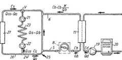
針5、6は図2に示されたチューブシステム7に接続され、透析循環路のような血液ポンプ8を含む体外循環路を形成する。血液ポンプは血液を血管から動脈針、体外循環路、静脈針を通して駆動し、血管中に戻す。 The
更に、図2に示された体外血液循環路7は、万一誤りが発生したら患者を体外循環路から隔離するための、動脈クランプ9及び静脈クランプ10を含む。 Further, the
ポンプ8の下流は透析装置11であり、半透膜14により隔てられた血液区画12、及び透析流体区画13を備える。更に、透析装置の下流は点滴チャンバ15であり、そこで空気を血液から分離する。 Downstream of the
血液は、動脈針から動脈クランプ9を通り過ぎて血液ポンプ8まで流れる。血液ポンプは、血液を駆動して透析装置11を通し、更に点滴チャンバ15を経由して静脈クランプ10を通過させ、静脈針を経由して患者に戻す。点滴チャンバは空気検出器を含んでもよく、空気検出器は点滴チャンバから放出された血液が空気又は気泡を万一含んでいたらアラームを起動するように調整される。血液循環路は、圧力センサ等のような他の構成要素を含んでもよい。 Blood flows from the arterial needle through the
透析装置11の透析流体区画13は、透析流体を第1のポンプ16によって供給され、第1のポンプ16は透析流体を、純水(一般にRO(逆浸透膜)水)の供給源、及び1つ又は複数のイオン濃縮物から、そのような濃縮物を計量するために示されるポンプ17、18で計量しながら得る。透析流体の準備は従来通りなので、ここではこれ以上記載しない。 The
血液及び透析流体の間の物質の交換は、透析装置の中で半透膜を通して行われる。特に、尿素は、血液から半透膜を通って、膜の他の側に存在する透析流体まで流れる。交換は濃度勾配の影響下にある拡散により行われ(いわゆる血液透析)、及び/又は血液から透析流体への液体の流れによる対流により行われ(いわゆる限外濾過)、それは血液透析又は血液濾過の重要な特徴である。 The exchange of substances between blood and dialysis fluid takes place through the semipermeable membrane in the dialysis machine. In particular, urea flows from the blood through the semipermeable membrane to the dialysis fluid present on the other side of the membrane. The exchange is carried out by diffusion under the influence of a concentration gradient (so-called hemodialysis) and / or by convection by the flow of liquid from the blood to the dialysis fluid (so-called ultrafiltration), which can be either hemodialysis or hemofiltration It is an important feature.
透析装置の透析流体区画13から放出される流体は透析液と呼ばれ、第2のポンプ19により尿素モニタ20を経てドレインまで駆動される。尿素モニタは透析装置から放出された透析液中の尿素濃度を連続的に測定し、透析治療の間ずっと透析液の尿素濃度曲線を提供する。そのような尿素濃度曲線は、WO9,855,166号に記載されるように身体の全尿素質量を得るため、及び前記出願に記載されるように全身の透析投与量Kt/Vの予測を得るためのような複数の目的のために使用できる。WO9,855,166号の内容は、本明細書に参考文献として引用される。 The fluid discharged from the
上記のように、本発明は、図2で示されるような尿素モニタ及び透析循環路を使用して、動脈針の直前で瘻孔中のアクセス流を非観血的に測定するための方法を提供する。 As mentioned above, the present invention provides a method for noninvasively measuring access flow in the fistula just before the arterial needle using a urea monitor and dialysis circuit as shown in FIG. To do.
通常の透析の間ずっと透析尿素濃度を測定し、次に針の位置を反転させ、反転位置の針を用いて透析尿素濃度を測定することにより、血液又は透析流体に物質を加えることなく、ブラッドアクセス中の血流を測定することができる。 Blood is measured without adding substance to the blood or dialysis fluid by measuring the dialysis urea concentration throughout normal dialysis, then reversing the position of the needle and measuring the dialysis urea concentration using the needle in the reversed position. Blood flow during access can be measured.
図3は、患者の血管回路及び図2による透析循環路の一部の略図を示す。患者の血液循環路は心臓を含み、心臓の右チャンバは上部ポンプ21で表され、心臓の左チャンバは下部ポンプ22で表される。肺23は上部及び下部ポンプの間に位置する。心臓の左チャンバポンプ22の出口から、血流はアクセス25に通じる第1の枝24(通常は患者の左前腕)、及びブロック27で表される臓器、他の四肢、頭部、等のような身体の残りの部分に通じる第2の枝26に分岐する。身体、臓器等(即ち、ブロック27)から戻った血液はアクセスから戻った血液と混ざり、右チャンバポンプ21に入る。 FIG. 3 shows a schematic representation of the patient's vascular circuit and a portion of the dialysis circuit according to FIG. The patient's blood circuit includes the heart, with the right chamber of the heart represented by the
心臓の拍出流量はQcoで定義され、アクセスの流量はQaで定義され、これはQco−Qaがブロック27に入ることを意味する。ブロック27から戻った静脈血がアクセスからの血液と混ぜ合わされる前に、全身の静脈血は尿素濃度Csを有する。左チャンバポンプ22を出た血液は、アクセス25及びブロック27に出ていく尿素濃度と等しい尿素濃度Caを有する。 The cardiac output is defined by Qco and the access flow is defined by Qa, which means that Qco-Qa enters
アクセス流量を測定するために、動脈針及び静脈針を通る流れを反転させる必要がある。それを達成する1つの方法は、手動で針を反転させることである。 In order to measure access flow, it is necessary to reverse the flow through the arterial and venous needles. One way to achieve that is to manually flip the needle.
或いは、図5は同じ操作を行うためのバルブ28を示す。動脈針5はバルブの動脈入口ライン29に接続され、静脈針6はバルブの静脈出口ライン30に接続される。血液ポンプはバルブの第1の出口ライン31に接続され、透析装置11から戻った血液はバルブの第2の出口ライン32に接続される。 Alternatively, FIG. 5 shows a
バルブはバルブハウジング及び回転可能なバルブ部材33から成り、バルブ部材33は図示される通常位置から通常位置に対して90度回転した反転位置まで回転可能である。 The valve includes a valve housing and a
図5に示される通常位置では、動脈針5は血液ポンプ8に接続され、静脈針6は透析装置の出口に点滴チャンバを経由して接続される(図2を参照)。反転位置では、必要に応じて、動脈針5は透析装置の出口に接続され、静脈針6は血液ポンプ8に接続される。 In the normal position shown in FIG. 5, the
バルブ配置の他の実施例が図7〜図9に示される。図7の実施例では、動脈ライン29は広げられた開口部29aに接続され、静脈出口ライン30は広げられた開口部30aに接続され、これら開口部はバルブハウジング28a中に互いに反対向きに配置されている。2つの広げられた開口部3la、32aがバルブハウジング28a中に互いに反対向きに、広げられた開口部29a、30aに対して90度変位させて配置される。回転可能なバルブ部材33aは通常は図7に示されるように配置され、バルブチャンバを2つの半円部分に分割する隔壁を形成する。バルブ部材は、広げられた開口部の周辺寸法より小さい幅を有する。バルブ部材は反転位置まで90度回転可能であり(図9に示される)、反転位置では動脈針及び静脈針を通る血流は反転される。 Another embodiment of the valve arrangement is shown in FIGS. In the embodiment of FIG. 7, the
通常位置から反転位置への移動の間ずっと、バルブ部材33aは図8に示されるアイドル位置を通過し、アイドル位置では4つの広げられた開口部の全てが相互接続している。何故ならば、バルブ部材の幅が広げられた開口部の周辺寸法より小さいからである。このアイドル位置により、血球に対する害を回避できる。そのような害は、もし血液ポンプへの入口ライン31又は透析装置からの出口ライン32が完全に閉塞したら生じる高いずれ応力により発生する。アイドル位置によって、血液針が流れの急激な変化にさらされないという他の長所が得られ、流れの急激な変化は場合によっては針の抜けを招くことさえある。バルブ部材が通常位置からアイドル位置まで動かされるとき、針を通る流れは、例えば、250ミリリットル/分の通常の流れから基本的にゼロの流れまで変化する。バルブ部材はアイドル位置に数秒間配置されてもよい。次に、バルブ部材は反転位置まで動かされ、針を通る流れが基本的にゼロの流れから250ミリリットル/分まで変化させられる。この方法で、通常の流れ及び反転した流れの間の更に穏やかな切り替えが得られる。 During the movement from the normal position to the reverse position, the
開口部及びバルブ部材の位置が異なってもよいので、回転運動は90度より小さくても大きくてもよいことに注意しなければならない。更に、開口部は所望する動作を達成するために反対向きに配置される必要はない。更に、広げられた開口部のサイズはチューブ及びラインに対して釣り合いが取れないが、以下で更に詳細に記載されるように、広げられた開口部の直径はチューブの内径とかなり同じ寸法である。 It should be noted that the rotational movement may be less than or greater than 90 degrees as the position of the opening and the valve member may be different. Further, the openings need not be placed in the opposite orientation to achieve the desired operation. Furthermore, the size of the widened opening is unbalanced for the tube and line, but the diameter of the widened opening is much the same as the inner diameter of the tube, as described in more detail below. .
バルブはデッドエンド部分をできるだけ持たないように構成され、デッドエンド部分では血液が溜まって凝固するかもしれないことに注意しなければならない。図から、バルブ本体のどの部分でもバルブはデッドエンド構造を持たないことが分かる。 It should be noted that the valve is configured to have as little dead end as possible and blood may accumulate and clot in the dead end. From the figure, it can be seen that the valve has no dead end structure in any part of the valve body.
更に、バルブを組み込んだ他の略図が図10に示される。図10は図5とポンプ8aの配置の点で全く異なり、図10による実施例のポンプ8aは動脈針5及びバルブ28の間に配置される。この方法では、バルブ本体33の両端間の圧力は、図5による実施例と比較して小さい。操作は少し難しい。血液ポンプが停止され、バルブが反転位置にされる。最後に、ポンプが始動され、ポンプの回転方向を反転させることにより血液を反対方向に送り込む。 Yet another schematic incorporating a valve is shown in FIG. FIG. 10 is completely different from FIG. 5 in the arrangement of the pump 8 a, and the pump 8 a of the embodiment according to FIG. 10 is arranged between the
バルブのどちらの位置でも患者に空気が誘導されないことを確認するために、空気検出器34、35を各動脈針及び静脈針それぞれの直前、又は少なくとも動脈針の前に追加することは有益である。血管に戻された血液中の気泡を万一測定したら、空気検出器はアラームを起動させる。一般に、点滴チャンバ中の空気検出器は、この目的のために十分である。 It may be beneficial to add
本発明で使用することを意図するバルブの詳細な構造が、図12〜図14で開示される。バルブは、2つの入口コネクタ及び2つの出口コネクタを備えたバルブハウジング36を含む。4つのコネクタ全てが円筒バルブチャンバ41の方向に開いており、4つの開口部は互いに90度ずつずれている。 The detailed structure of the valve intended for use with the present invention is disclosed in FIGS. The valve includes a
図14に示されるように、バルブは動脈針5に接続される血液入口コネクタ37、及び静脈針6に接続される血液出口コネクタ38を含む。コネクタ部分は、雌のルアー(Luer)コネクタで終端する可撓チューブに接続される雄のルアーコネクタとして配置される。 As shown in FIG. 14, the valve includes a
更に、バルブは、血液ポンプ8に接続される回路出口コネクタ39、及び透析装置出口に接続される回路入口コネクタ40を含む。コネクタ部分39、40は、回路の雄のルアーコネクタと結合する雌のルアーコネクタとして配置される。 Further, the valve includes a
図12からわかるように、円筒バルブチャンバ41は底面が閉じている。上面から、バルブ部材42が円筒バルブチャンバ内部に差し込まれる。図13からわかるように、バルブ部材42はバルブ隔壁43を含む。 As can be seen from FIG. 12, the bottom surface of the
また、バルブ部材は作動ウィング44を含み、作動ウィング44によってバルブ部材は通常位置(通常位置ではバルブ隔壁43が図14で点線により示されるように位置する)及び反転位置の間で90度回転する。回転運動はバルブ部材42の肩45により制限され、肩45はバルブハウジング中の溝46と協働する。肩45は、通常位置及び反転位置でそれぞれ2つの逃げ47、48と協働してバルブ部材を各位置に保持する突起46aを備える。溝46は第3の逃げ(図示されない)を備えて前記アイドル位置を定めてもよい。そのような第3の逃げは、2つの逃げ47、48の間の中間に位置する。 Further, the valve member includes an operating
バルブ部材及びハウジングは、適切なシーリングを備えて安全な動作を保証する。バルブの動作は上記の記載から明らかである。 The valve member and housing are provided with appropriate sealing to ensure safe operation. The operation of the valve is clear from the above description.
所定の透析装置浄化値K、所定のアクセス血流Qa、及び身体から戻った全身性静脈血中の所定の血液尿素濃度Csに基づく理論的な透析液尿素濃度を研究することにより、心肺の再循環を考慮に入れると、透析装置の尿素有効浄化値Keffはアクセス流の計算に必要とされることが分かる。有効浄化値は、例えばEP658,352号に記載されるように測定でき、EP658,352号の内容は、本明細書に参考文献として引用される。 By studying a theoretical dialysate urea concentration based on a predetermined dialyzer purification value K, a predetermined access blood flow Qa, and a predetermined blood urea concentration Cs in systemic venous blood returning from the body, Taking into account the circulation, it can be seen that the urea effective purification value Keff of the dialysis machine is required for the calculation of the access flow. Effective purification values can be measured, for example, as described in EP 658,352, the contents of EP 658,352 being incorporated herein by reference.
或いは、有効浄化値は、例えば血液サンプルによる全身性静脈血の尿素濃度Cs及び透析液の尿素濃度Cdの同時測定値からも計算できる。 Alternatively, the effective purification value can be calculated from, for example, the simultaneous measurement values of the urea concentration Cs of systemic venous blood and the urea concentration Cd of dialysate from a blood sample.
全身性血液尿素濃度Csは、いわゆる、ストップフロー−スローフロー(stop flow-slow flow)法により測定でき、血流を実質的に2分停止して心肺の再循環を平衡にすることを可能にする。その後、血液サンプルを採取する前に、ポンプはゆっくり動かされて動脈ラインを新鮮な血液で充填する。そうして得た血液サンプル中の尿素濃度は、身体から心臓に戻った全身性静脈血中の尿素濃度Csと等しい。 Systemic blood urea concentration Cs can be measured by the so-called stop flow-slow flow method, allowing blood flow to be substantially stopped for 2 minutes to balance cardiopulmonary recirculation To do. The pump is then slowly moved to fill the arterial line with fresh blood before taking a blood sample. The urea concentration in the blood sample thus obtained is equal to the urea concentration Cs in systemic venous blood returning from the body to the heart.
血液サンプルを採取する代わりに、膜の他の側の透析流体流を停止して、ゆっくり流れる血液が膜の他の側の透析液と平衡になるようにすると、透析液の尿素濃度が測定されて全身性静脈血尿素濃度Csが得られる。 Instead of taking a blood sample, dialysis fluid flow on the other side of the membrane is stopped so that the slowly flowing blood equilibrates with the dialysate on the other side of the membrane, and the urea concentration in the dialysate is measured. Thus, the systemic venous blood urea concentration Cs is obtained.
有効浄化値を得る他の方法が、WO9,929,355号に記載されている。WO9,929,355号に記載された発明によると、全身性血液濃度Csは、治療の前又は開始時に、例えば血液サンプルを用いたストップフロー−スローフロー法、又は上記のような平衡化により測定される。有効な透析液尿素濃度値Cdを透析装置出口ラインに接続された尿素モニタから得た後、治療開始時の透析液初期尿素濃度Cdinitが、得られた透析液尿素曲線により推定される。Another method for obtaining an effective purification value is described in WO 9,929,355. According to the invention described in WO 9,929,355, the systemic blood concentration Cs is measured before or at the start of the treatment, for example by a stop flow-slow flow method using a blood sample, or equilibration as described above. Is done. After obtaining an effective dialysate urea concentration value Cd from the urea monitor connected to the dialyzer outlet line, the initial dialysate urea concentration Cdinit at the start of treatment is estimated from the obtained dialysate urea curve.
全身性血液尿素濃度Csを得る更に他の方法は、全身の尿素質量Mwhを計算し、治療開始における尿素質量を外挿して推定することである。全身の尿素質量Mwhを分布容積Vで割ることにより、治療開始における全身性血液尿素濃度Csが得られる。Yet another method of obtaining the systemic blood urea concentration Cs is to calculate the whole body urea massMwh and extrapolate and estimate the urea mass at the start of treatment. By dividing the total body urea massMwh by the distribution volume V, the systemic blood urea concentration Cs at the start of treatment is obtained.
透析液尿素濃度Cdを全身性血液尿素濃度Csで割り、透析液流量Qdを掛けることにより、実効浄化値Keffが得られる。治療の初期に実効浄化値Keffを測定することは有益である。 The effective purification value Keff is obtained by dividing the dialysate urea concentration Cd by the systemic blood urea concentration Cs and multiplying by the dialysate flow rate Qd. It is beneficial to measure the effective clearance value Keff early in the treatment.
更に、本発明の方法では、動脈針及び静脈針中の血流が反転される。通常位置の針、及び反転位置の針の2つの状況の透析液尿素濃度は、図3及び図4を参照すると、以下のように計算される。 Furthermore, in the method of the present invention, the blood flow in the arterial and venous needles is reversed. With reference to FIGS. 3 and 4, the dialysate urea concentration in the two situations of the normal position needle and the inverted position needle is calculated as follows.
ラインが反転されたとき、身体から戻った静脈血中の血液尿素濃度Csは変化しないと想定され、透析装置浄化値Kも変化しないと想定される。話を簡単にするために、限外濾過をゼロと仮定するが、ゼロでない限外濾過も処理することが可能である。次の記号が使用される。
Qco=心臓の拍出
Qa=アクセス流
Qb=体外循環路中の血流
Qd=透析液流
K=透析装置浄化値
Keff=透析装置有効浄化値
Cs=身体から戻った全身性静脈血中の血液尿素濃度
Ca=アクセスの中の血液尿素濃度
Cb=透析装置入口における血液尿素濃度
Cd=透析液尿素濃度
浄化値は、次の式で定義される。
K=(除去された尿素)/Cb=Qd*Cd/Cb (1)When the line is reversed, it is assumed that the blood urea concentration Cs in the venous blood returned from the body does not change, and the dialyzer purification value K does not change. For simplicity, it is assumed that ultrafiltration is zero, but non-zero ultrafiltration can also be handled. The following symbols are used:
Qco = cardiac output Qa = access flow Qb = blood flow in extracorporeal circuit Qd = dialysate flow K = dialysis device purification value Keff = dialysis device effective purification value Cs = blood in systemic venous blood returned from the body Urea concentration Ca = blood urea concentration in access Cb = blood urea concentration Cd at dialyzer inlet Cd = dialysate urea concentration The purification value is defined by the following equation.
K = (removed urea) / Cb = Qd * Cd / Cb (1)
Qa>Qbであり、針が通常位置にある場合を最初に考える。
この場合、Cb=Caである。Consider first when Qa> Qb and the needle is in the normal position.
In this case, Cb = Ca.
血液からの除去は透析液中の状況と等しくなければならないので、次の式が成り立つ。
K*Ca=Qd*Cd (2)Since removal from the blood must be equal to the situation in the dialysate, the following equation holds:
K * Ca = Qd * Cd (2)
静脈還流血をアクセスからの血液と混ぜるとき、点V(図3参照)における尿素に対する質量平衡は次の式を与える。
Ca*Qco=Cs*(Qco−Qa)+Ca*(Qa−K) (3)
従って、Ca及びCsの間の関係を得る。
式(2)及び式(3)を組み合わせることにより、次の式を得る。
Cd=(K/Qd)*Cs/[1+K/(Qco−Qa)] (4)When the venous return blood is mixed with the blood from the access, the mass balance for urea at point V (see FIG. 3) gives:
Ca * Qco = Cs * (Qco-Qa) + Ca * (Qa-K) (3)
Therefore, a relationship between Ca and Cs is obtained.
The following formula is obtained by combining the formula (2) and the formula (3).
Cd = (K / Qd) * Cs / [1 + K / (Qco−Qa)] (4)
実効浄化値Keffの定義は、透析装置浄化値で通常使用されるように、CsはCbの代わりに分母で使用されなければならないことを示し、次の式を意味する。
Keff=K*(Cb/Cs)=K/[1+K/(Qco−Qa)] (5)The definition of effective purification value Keff indicates that Cs must be used in the denominator instead of Cb, as is normally used in dialyzer purification values, and means:
Keff = K * (Cb / Cs) = K / [1 + K / (Qco−Qa)] (5)
反転ラインの場合に戻ると(図4参照)、血液から除去されるものは透析液に入らなければならず、この場合、次の式を得る。
K*Cb=Qd*Cd (6)Returning to the case of the inversion line (see FIG. 4), what is removed from the blood must enter the dialysate, in which case the following equation is obtained:
K * Cb = Qd * Cd (6)
針の間の瘻孔中の流れはQa+Qbであり、透析装置入口における血液尿素濃度は、透析された血液がアクセスに再び入る点Pにおける尿素質量平衡から計算できる。
Cb*(Qb−K)+Ca*Qa=Cb*(Qb+Qa) (7)The flow in the fistula between the needles is Qa + Qb and the blood urea concentration at the dialyzer inlet can be calculated from the urea mass balance at point P where dialyzed blood reenters the access.
Cb * (Qb-K) + Ca * Qa = Cb * (Qb + Qa) (7)
静脈還流血がアクセス還流中の透析された血液と合流する点Qにおける質量平衡もある。
Ca*Qco=Cs*(Qco−Qa)+Cb*Qa (8)
Ca及びCbを消去することにより、次の式を得る。
Cd=(K/Qd)*Cs/[1+(Qco/Qa)*K/(Qco−Qa] (9)There is also a mass balance at point Q where the venous return blood meets the dialyzed blood during access return.
Ca * Qco = Cs * (Qco-Qa) + Cb * Qa (8)
By erasing Ca and Cb, the following equation is obtained.
Cd = (K / Qd) * Cs / [1+ (Qco / Qa) * K / (Qco−Qa] (9)
Cs、K、及びQdが2つの場合で変化しないので、透析液尿素濃度の比を得ることができる。
Cdnorm/Cdrev=1+(K/Qa)/[1+K/(Qco−Qa)]=1+Keff/Qa (10)Since Cs, K, and Qd do not change in the two cases, the ratio of dialysate urea concentration can be obtained.
Cdnorm / Cdrev = 1 + (K / Qa) / [1 + K / (Qco−Qa)] = 1 + Keff / Qa (10)
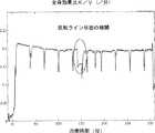
実際には、各側からの切り替えの時間に対する外挿による推定を用いて、2つの透析液尿素濃度はラインの切り替え前後の透析液尿素曲線にフィットする曲線によりかなり良く見わけられる。通常の血液透析治療の間の透析液の尿素濃度Cdを示す図6を参照されたい。 In practice, using an extrapolated estimate of the switching time from each side, the two dialysate urea concentrations can be fairly well distinguished by a curve that fits the dialysate urea curve before and after line switching. See FIG. 6 which shows the urea concentration Cd of the dialysate during normal hemodialysis treatment.
図6で丸印を付けられた約10分間ずっと、動脈針及び静脈針が反転する。尿素モニタが正確に測定することを可能にするための初期期間の後、反転ライン状態の尿素濃度は元の尿素濃度の約0.8倍であり、それはCdnorm/Cdrev=1.25であることを意味する。従って、もし通常位置の針で測定するか又は上記のように推定したようにKeffが200ミリリットル/分であれば、アクセス流は800ミリリットル/分である。The arterial and venous needles are inverted for about 10 minutes as circled in FIG. After an initial period to allow the urea monitor to measure accurately, the urea concentration in the reverse line state is about 0.8 times the original urea concentration, which is Cdnorm / Cdrev = 1.25. It means that there is. Thus, if measured with a needle in the normal position or as estimated above, Keff is 200 ml / min, the access flow is 800 ml / min.
また、有効浄化値は、血液流及び透析装置流、並びに透析装置特性(例えば、透析装置のデータシート)から概算として得られる。 Also, the effective purification value is obtained as an approximation from the blood flow and dialyzer flow and dialyzer characteristics (eg, dialyzer data sheet).
本明細書では、3つの異なる浄化値、即ち透析装置浄化値、有効浄化値、及び全身(whole body)浄化値が使用される。もし透析装置浄化値が一定の血流量及び透析液流量に対して250ミリリットル/分であれば、有効浄化値は例えば230ミリリットル/分であるように、一般に5〜10%低い。全身浄化値は例えば200ミリリットル/分であるように、更に5〜15%低い。透析装置浄化値は、透析装置で直接測定した浄化値である。また、有効浄化値は、心肺の再循環を考慮に入れた浄化値である。最後の、全身浄化値は、身体の任意の部分から透析装置への尿素の流れを制限する身体の他の膜を更に考慮に入れた有効浄化値である。全身浄化値の概念はWO9,855,166号に記載されており、WO9,855,166号の内容は、本明細書に参考文献として引用される。 In this specification, three different purification values are used: dialyzer purification values, effective purification values, and whole body purification values. If the dialyzer purification value is 250 milliliters / minute for a constant blood flow and dialysate flow rate, the effective purification value is generally 5-10% lower, for example 230 milliliters / minute. The whole body cleansing value is 5-15% lower, for example 200 ml / min. The dialyzer purification value is a purification value directly measured by the dialyzer. The effective purification value is a purification value taking into account cardiopulmonary recirculation. Finally, the whole body cleansing value is an effective cleansing value that further takes into account other membranes in the body that limit the flow of urea from any part of the body to the dialyzer. The concept of the whole body purification value is described in WO 9,855,166, and the contents of WO 9,855,166 are cited in this specification as a reference.
また、公式で使用される有効浄化値は、通常位置の針を用いる上記のEP658,352号に記載された方法による測定からも得られる。これは血漿水尿素有効浄化値の基準を与え、次に血漿水尿素有効浄化値は全血(whole blood clearance)浄化値に変換されなければならない。EP658,352号の方法は、基本的に、透析装置の上流の透析流体の伝導率が例えば10%だけ増加して元の値に戻ることを含む。透析装置の出口側における結果が測定され、透析装置の実効浄化値Keffの基準となる。 The effective purification value used in the formula can also be obtained from measurements by the method described in EP 658,352 above using a needle in the normal position. This provides a basis for the plasma water urea effective clearance value, which must then be converted to a whole blood clearance clearance value. The method of EP 658,352 basically involves increasing the conductivity of the dialysis fluid upstream of the dialyzer, eg by 10%, back to its original value. The result at the outlet side of the dialyzer is measured and serves as a reference for the effective purification value Keff of the dialyzer.
或いは、有効浄化値は式Keff=Qd*Cd/Csによって計算できる。全身の静脈尿素濃度は透析液尿素濃度Cdと同時に、又は上記の方法により測定できる。 Alternatively, the effective purification value can be calculated by the equation Keff = Qd * Cd / Cs. The systemic venous urea concentration can be measured simultaneously with the dialysate urea concentration Cd or by the method described above.
他の方法は、上記のWO9,855,166号による方法により得られた身体尿素質量の総計値Mureaを使用する。尿素分布容積VをWatsonの公式又は他の方法によって得ることにより、静脈尿素濃度は次の式でほぼ表される。
Cs=Murea/V (11)The other method uses the total body urea mass value Murea obtained by the method according to the above-mentioned WO 9,855,166. By obtaining the urea distribution volume V by Watson's formula or other methods, the venous urea concentration is approximately expressed by the following equation:
Cs = Murea / V (11)
WO9,855,166号の方法では、透析プロセスの全身効果比Kwb/Vが得られる。下付文字wbにより示されるように、全身浄化値が使用されることに注意しなければならない。前記WO9,855,166号によると、次の式によって尿素濃度は全身効果比に比例する。
Kwb/V=(Qd*Cd)/m (12)In the method of WO 9,855,166, a systemic effect ratio Kwb / V of the dialysis process is obtained. Note that the whole body purification value is used, as indicated by the subscript wb. According to WO 9,855,166, the urea concentration is proportional to the systemic effect ratio according to the following equation.
Kwb / V = (Qd * Cd) / m (12)
従って、もし(Kwb/V)がCdの代わりに上記の式(10)で使用されたら、類似の結果が得られ、もしmが一定なら、即ち、測定が同じ時間インスタンスに対して外挿される、と仮定すると、次の式を得る。
(Kwb/V)norm/(Kwb/V)rev=1+Keff/Qa (13)Thus, if (Kwb / V) is used in equation (10) above instead of Cd, a similar result is obtained, if m is constant, ie the measurement is extrapolated for the same time instance. Assuming that
(Kwb / V)norm / (Kwb / V)rev = 1 + Keff / Qa (13)
前記WO9,855,166号で述べられるように、全身効果比を透析液尿素測定だけから計算することが可能である。通常位置及び反転位置の比にだけ関心があるので、実際のKwbを計算する必要はない。As described in WO 9,855,166, the systemic effect ratio can be calculated solely from the dialysate urea measurement. Since we are only interested in the ratio of the normal position and the inversion position, it is not necessary to calculate the actual Kwb .
図11は、全身効果比K/V(/分)のグラフを示す。反転ライン状態の期間が円の内側に示される。他の全側面では、上記と同じ議論が適用される。 FIG. 11 shows a graph of the systemic effect ratio K / V (/ min). The period of the inverted line state is shown inside the circle. In all other aspects, the same arguments apply as above.
上記の計算は、体外血流量Qbがアクセス流量Qaを越えないと仮定している。この場合には、針が通常位置にあるときにアクセス再循環が存在するようになり、アクセスの中の流れは反転するであろう。透析液尿素濃度の計算は反転位置にある針に対して変更されないが、通常位置にある針に対しては修正されなければならない。上記のそれらに対応する計算は、通常位置及び反転位置にある針に対する透析液尿素濃度の間の上記の比が次の式のようであることを示す。
Cdnorm/Cdrev=1+Keff/Qb (14)
ここで、Keffは再循環の効果を含む有効浄化値であり、即ち針は通常位置にある。The above calculation assumes that the extracorporeal blood flow Qb does not exceed the access flow Qa. In this case, access recirculation will exist when the needle is in the normal position and the flow in the access will be reversed. The calculation of dialysate urea concentration is not changed for the needle in the inverted position, but must be corrected for the needle in the normal position. The corresponding calculations above show that the above ratio between the dialysate urea concentrations for the needles in the normal position and the inverted position is as follows:
Cdnorm / Cdrev = 1 + Keff / Qb (14)
Here, Keff is an effective purification value including the effect of recirculation, that is, the needle is in the normal position.
唯一の違いは、今や計算がアクセス流の代わりに体外血流量Qbを与えることである。この血流は既知であり、従ってこれは実際にはアクセス流量Qaが血流量Qbに接近する結果になるとき、再循環を疑わなければならないことを意味し、これはアクセスが改善されなければならないことを常に意味する。 The only difference is that the calculation now gives extracorporeal blood flow Qb instead of access flow. This blood flow is known, so this actually means that recirculation must be suspected when the access flow Qa results in approaching the blood flow Qb, which must improve access. That always means.
Keff/Qbは1より小さい数値であり、一般に、例えば0.6〜0.9である。Keff/Qaは相当に低くなければならず、例えば0.1〜0.4である。従って、Cdnorm/Cdrevが、1.2又は1.5等の予め定められた数値に到達したとき、又は予め定められた数値より低いとき、アクセス再循環が存在するかどうかを決定するために、更に一層の計算を行わなければならない。Keff / Qb is a numerical value smaller than 1, and is generally, for example, 0.6 to 0.9. Keff / Qa must be fairly low, for example 0.1-0.4. Thus, to determine whether access recirculation exists when Cdnorm / Cdrev reaches a predetermined value such as 1.2 or 1.5 or is lower than a predetermined value. In addition, further calculations must be performed.
単純な手順は、血流量Qbをある程度減少させることである。もしその後透析液濃度が減少したら、これは少なくとも低い血流においてアクセス再循環又は瘻孔再循環が存在しないことを意味する。 A simple procedure is to reduce the blood flow Qb to some extent. If the dialysate concentration subsequently decreases, this means that there is no access recirculation or fistula recirculation at least in the low blood flow.
また、上記の計算は限外濾過が存在する状況に対しても行える。しかし、測定間隔の間ずっと限外濾過をゼロまで減少させることが簡単な手法である。更に、限外濾過により導入される誤差は小さく、無視できる。 The above calculations can also be performed for situations where ultrafiltration exists. However, a simple approach is to reduce ultrafiltration to zero throughout the measurement interval. Furthermore, the errors introduced by ultrafiltration are small and can be ignored.
測定は時間間隔の間に行わなければならず、時間間隔は30秒よりも相当に長いので、心肺の再循環が進展する。有効な結果を得るための測定時間は針を反転した状態では5分でよく、一方、針が正しい位置にある状態での測定は5分で又は治療の間続けて行われる。 Measurements must be made during the time interval, and since the time interval is much longer than 30 seconds, cardiopulmonary recirculation progresses. The measurement time for obtaining a valid result may be 5 minutes with the needle inverted, while the measurement with the needle in the correct position is performed in 5 minutes or continuously during treatment.
また、この方法は、透析装置の前又は後での血液への透析液の点滴(血液濾過及び血液透析と呼ばれる)を含む治療方法にも適用できる。その結果は、上記と同じである。 This method can also be applied to treatment methods involving instillation of dialysate into the blood before or after the dialyzer (referred to as hemofiltration and hemodialysis). The result is the same as above.
もしアクセスが静脈カテーテルなら、心肺の再循環は存在せず、計算は更に簡単になる。全身の静脈尿素濃度Csが透析装置入口の尿素濃度Cbと同じになるので、実効浄化値Keffが透析装置浄化値Kに取って代わられることを除いて、結果は同じである。 If the access is a venous catheter, there is no cardiopulmonary recirculation and the calculation is further simplified. Since the whole body venous urea concentration Cs becomes the same as the urea concentration Cb at the dialyzer inlet, the result is the same except that the effective purification value Keff is replaced by the dialyzer purification value K.
計算の中の全ての流量、浄化値、及び尿素濃度は全血に関連することに注意しなければならない。タンパク質濃度に依存するが血漿の約93%は水であり、赤血球の約72%が水である。ヘマトクリット値に依存して、血液の水分容積は全血容積の10〜13%以下である(例えば、John T. Daugirdas 及び Todd. S Ing著「Handbook of Dialysis」第二版、1994年の18ページを参照)。 It should be noted that all flow rates, clearance values, and urea concentrations in the calculations are related to whole blood. Depending on the protein concentration, about 93% of plasma is water and about 72% of red blood cells are water. Depending on the hematocrit value, the water volume of the blood is no more than 10-13% of the whole blood volume (eg John T. Daugirdas and Todd. S Ing, “Handbook of Dialysis” second edition, page 1994, page 18). See).
EP658,352号によって得た尿素有効浄化値は血液の水分に関し、従って、本発明の公式で使用される前に10〜13%だけ増加させなければならない。一般に、実験室からの血液尿素濃度値は血漿に関し、従って、全血と関連させるために約7%だけ減少させなければならない。 The urea cleansing value obtained by EP 658,352 relates to blood moisture and must therefore be increased by 10-13% before being used in the formula of the present invention. In general, blood urea concentration values from the laboratory relate to plasma and therefore must be reduced by about 7% in order to be associated with whole blood.
或いは、全ての尿素濃度、流量、及び浄化値を血液の水分と関連して使用してもよい。そうであれば有効浄化値は変化されずに使用されるが、計算されたアクセス流は血液の水分に関連するため、全血に関連して10〜13%だけ増加させなければならない。 Alternatively, all urea concentrations, flow rates, and purification values may be used in conjunction with blood moisture. If so, the effective clearance value is used unchanged, but the calculated access flow is related to blood moisture and must be increased by 10-13% relative to whole blood.
本発明について、人間の身体での使用に関して、尿素をアクセス流を測定するためのマーカとして使用して上記のように記載してきた。しかし、血液中に存在し、透析装置の透析液側で測定できる他の物質(例えば、クレアチニン、ビタミンB12、β−2−マイクログロブリン、NaCl、又はイオンの他の組み合わせ)も本発明によって使用できる。他の代案は、伝導率を測定することである。 The present invention has been described above for use in the human body, using urea as a marker for measuring access flow. However, other substances that are present in the blood and can be measured on the dialysate side of the dialyzer (eg, creatinine, vitamin B12, β-2-microglobulin, NaCl, or other combinations of ions) can also be used with the present invention. . Another alternative is to measure conductivity.
また、濃度に比例する特性を測定することも可能である。何故ならば、それが本発明の式に含まれる比だからである。従って、尿素濃度は流体を含む尿素をウレアーゼカラムに通した後に伝導率の差を測定することにより測定でき、そのような伝導率の差は式中の濃度値の代わりに直接使用できる。 It is also possible to measure a characteristic proportional to the concentration. This is because it is a ratio included in the formula of the present invention. Thus, urea concentration can be measured by measuring the conductivity difference after passing urea containing fluid through a urease column, and such conductivity difference can be used directly instead of the concentration value in the equation.
測定が透析装置の透析液側で行われる限り、前記の物質濃度を測定する他の間接的方法が使用できる。他の代案は、血液尿素濃度を既知の方法により透析装置の前又は後の何れかで測定することである。何故ならば、これらの濃度は公式中の濃度と比例するからである。 Other indirect methods of measuring the substance concentration can be used as long as the measurement is performed on the dialysate side of the dialyzer. Another alternative is to measure the blood urea concentration either by a known method either before or after the dialyzer. This is because these concentrations are proportional to the concentrations in the formula.
本発明は、人間の身体での使用を参照して上記のように記載してきた。しかし、本発明は、流体が通過し、流体が通過する部分が透析のために取り出される如何なるチューブシステム(例えば、ビール又はワインの製造)でも使用できる。 The present invention has been described above with reference to use in the human body. However, the present invention can be used with any tube system (eg, beer or wine production) through which fluid passes and where the fluid passes through are removed for dialysis.
1 前腕
2 動脈
3 静脈
4 瘻孔
5 動脈針
6 静脈針
7 体外血液循環路
8 ポンプ
9 動脈クランプ
10 静脈クランプ
11 透析装置
12 血液区画
13 透析流体区画
14 半透膜
15 点滴チャンバ
16、19 ポンプ
17、18 定量ポンプ
20 尿素モニタ
21 右チャンバ(上部)ポンプ
22 左チャンバ(下部)ポンプ
23 肺
24 第1の枝(左前腕)
25 アクセス
26 第2の枝
27 ブロック(左前腕以外の部分)
28 バルブ
28a バルブハウジング
29 動脈入口ライン
29a、30a 開口部
30 静脈出口ライン
31 バルブからの出口ライン
32 透析装置からの出口ライン
33 バルブ部材
33a バルブ部材
34、35 空気検出器
36 バルブハウジング
37 血液入口コネクタ
38 血液出口コネクタ
39、40 コネクタ部分
41 円筒バルブチャンバ
42 バルブ部材
43 バルブ隔壁
44 作動ウィング
45 肩
46 溝
46a 突起
47、48 逃げDESCRIPTION OF
25 Access 26
28
Claims (5)
Translated fromJapanese除去位置における流体流アクセスから、透析流体入口及び透析流体出口と半透膜とを有する透析装置を備える外部循環路へと第1の流体流を第1の流体流量で除去するための手段と、
前記第1の流体流を前記半透膜の一方側に沿って通過させるための手段、及び、透析流体を半透膜の他方側から放出させるための手段と、
前記第1の流体流を前記外部循環路から前記流体流アクセスへ前記除去位置の下流の帰還位置で戻すための手段と、
前記透析装置から放出された前記透析流体中の物質の濃度に基本的に比例する第1の変量を測定するための手段と、
前記第1の流体流量を変化させるための手段と、
前記透析装置から放出された透析流体中の前記物質の濃度をモニタするための手段とを備え、
アクセス再循環の検出が、前記第1の流体流量が減少する際、前記濃度の減少の欠如を検出することのみからなる態様で、前記濃度の変化を前記第1の流体流量の前記変化に関連づけることにより、起こり得るアクセス再循環を検出する装置。A device for detecting access recirculation,
Means for removing a first fluid flow at a first fluid flow rate from a fluid flow access at a removal location to an external circuit comprising a dialysis device having a dialysis fluid inlet and a dialysis fluid outlet and a semipermeable membrane;
Means for passing the first fluid stream along one side of the semipermeable membrane; and means for discharging dialysis fluid from the other side of the semipermeable membrane;
Means for returning the first fluid stream from the external circuit to the fluid stream access at a return position downstream of the removal position;
It means for measuring a first variable which essentially proportional to the concentration of theobject substancein the dialysis fluid discharged from thepre-Symbol dialyzer,
Means for changing the first fluid flow rate;
Means for monitoring the concentration of the substance in the dialysis fluid released from the dialysis machine,
The change in concentration is related to the change in the first fluid flow rate in such amanner that the detection of access recirculation consists only of detecting the lack of concentration decrease when the first fluid flow rate decreases. A device for detecting possible access recirculations.
Applications Claiming Priority (2)
| Application Number | Priority Date | Filing Date | Title |
|---|---|---|---|
| US10539698P | 1998-10-23 | 1998-10-23 | |
| US60/105,396 | 1998-10-23 |
Related Parent Applications (1)
| Application Number | Title | Priority Date | Filing Date |
|---|---|---|---|
| JP2000578044ADivisionJP4394288B2 (en) | 1998-10-23 | 1999-10-22 | Method and apparatus for measuring access flow |
Publications (3)
| Publication Number | Publication Date |
|---|---|
| JP2009268922A JP2009268922A (en) | 2009-11-19 |
| JP2009268922A5 JP2009268922A5 (en) | 2010-06-24 |
| JP5275170B2true JP5275170B2 (en) | 2013-08-28 |
Family
ID=22305607
Family Applications (2)
| Application Number | Title | Priority Date | Filing Date |
|---|---|---|---|
| JP2000578044AExpired - Fee RelatedJP4394288B2 (en) | 1998-10-23 | 1999-10-22 | Method and apparatus for measuring access flow |
| JP2009188465AExpired - Fee RelatedJP5275170B2 (en) | 1998-10-23 | 2009-08-17 | Method and apparatus for measuring access flow |
Family Applications Before (1)
| Application Number | Title | Priority Date | Filing Date |
|---|---|---|---|
| JP2000578044AExpired - Fee RelatedJP4394288B2 (en) | 1998-10-23 | 1999-10-22 | Method and apparatus for measuring access flow |
Country Status (9)
| Country | Link |
|---|---|
| EP (2) | EP2198900B1 (en) |
| JP (2) | JP4394288B2 (en) |
| KR (1) | KR100591574B1 (en) |
| CN (1) | CN1204930C (en) |
| AU (1) | AU759593B2 (en) |
| CA (1) | CA2345965C (en) |
| HK (1) | HK1040203A1 (en) |
| NZ (1) | NZ510869A (en) |
| WO (1) | WO2000024440A1 (en) |
Families Citing this family (52)
| Publication number | Priority date | Publication date | Assignee | Title |
|---|---|---|---|---|
| US6648845B1 (en)† | 1998-01-07 | 2003-11-18 | Fresenius Medical Care North America | Method and apparatus for determining hemodialysis parameters |
| US6726647B1 (en) | 1998-10-23 | 2004-04-27 | Gambro Ab | Method and device for measuring access flow |
| SE0100838D0 (en) | 2001-03-12 | 2001-03-12 | Jan Sternby | Method and apparatus for needle placement |
| US6676660B2 (en) | 2002-01-23 | 2004-01-13 | Ethicon Endo-Surgery, Inc. | Feedback light apparatus and method for use with an electrosurgical instrument |
| SE0200370D0 (en) | 2002-02-08 | 2002-02-08 | Gambro Lundia Ab | Method and apparatus for determining access flow |
| DE10259437B3 (en)* | 2002-12-19 | 2004-09-16 | Fresenius Medical Care Deutschland Gmbh | Method and device for determining blood flow in a blood-carrying line |
| CN1874803B (en)* | 2003-10-31 | 2010-09-15 | 甘布罗伦迪亚股份公司 | Circuit for extracorporeal blood treatment and flow-reversing device used therein |
| JP4573231B2 (en)* | 2006-11-01 | 2010-11-04 | 日機装株式会社 | Blood purification equipment |
| FR2911417B1 (en) | 2007-01-17 | 2009-02-27 | Gambro Lundia Ab | MONITORING THE VASCULAR ACCESS OF A PATIENT SUBJECTED TO SUCCESSIVE EXTRACORPOREAL BLOOD TREATMENT SESSIONS |
| CN101920049B (en)* | 2009-06-11 | 2014-03-12 | 四川大学华西医院 | Method and system for determining a recirculation rate and/or a recirculation quantity of a dialysis circuit |
| US9399091B2 (en) | 2009-09-30 | 2016-07-26 | Medtronic, Inc. | System and method to regulate ultrafiltration |
| EP2519279B1 (en) | 2009-12-28 | 2015-04-22 | Gambro Lundia AB | Device and method for monitoring a fluid flow rate in a cardiovascular system |
| ES2440366T3 (en) | 2010-04-13 | 2014-01-28 | Gambro Lundia Ab | Connector for a fluid transport conduit of a medical device |
| US9561316B2 (en) | 2011-04-29 | 2017-02-07 | Medtronic, Inc. | Intersession monitoring for blood fluid removal therapy |
| CN103889481B (en) | 2011-08-02 | 2016-03-09 | 美敦力公司 | Hemodialysis system with flow path with controlled compliance volume |
| EP2744537B1 (en) | 2011-08-16 | 2018-01-24 | Medtronic, Inc. | Modular hemodialysis system |
| WO2014033782A1 (en)* | 2012-08-30 | 2014-03-06 | テルモ株式会社 | Extracorporeal circulation device, control device, and control method therefor |
| US10905816B2 (en) | 2012-12-10 | 2021-02-02 | Medtronic, Inc. | Sodium management system for hemodialysis |
| US10010663B2 (en) | 2013-02-01 | 2018-07-03 | Medtronic, Inc. | Fluid circuit for delivery of renal replacement therapies |
| US10850016B2 (en) | 2013-02-01 | 2020-12-01 | Medtronic, Inc. | Modular fluid therapy system having jumpered flow paths and systems and methods for cleaning and disinfection |
| US10543052B2 (en) | 2013-02-01 | 2020-01-28 | Medtronic, Inc. | Portable dialysis cabinet |
| US9623164B2 (en) | 2013-02-01 | 2017-04-18 | Medtronic, Inc. | Systems and methods for multifunctional volumetric fluid control |
| US9827361B2 (en) | 2013-02-02 | 2017-11-28 | Medtronic, Inc. | pH buffer measurement system for hemodialysis systems |
| DE102013103220A1 (en)* | 2013-03-28 | 2014-10-02 | B. Braun Avitum Ag | Method and device for determining a recirculation state |
| DE102013103221A1 (en)* | 2013-03-28 | 2014-10-02 | B. Braun Avitum Ag | Method for detecting recirculation in an arteriovenous shunt during ongoing hemodialysis and dialysis |
| EP2792377A1 (en) | 2013-04-15 | 2014-10-22 | Gambro Lundia AB | Medical infrastructure and medical monitoring apparatus for surveillance of patients over a plurality of extracorporeal blood treatment sessions |
| JP6312118B2 (en)* | 2013-05-16 | 2018-04-18 | 学校法人東京理科大学 | Electric characteristic measuring apparatus, electric characteristic measuring method and program |
| US10076283B2 (en) | 2013-11-04 | 2018-09-18 | Medtronic, Inc. | Method and device to manage fluid volumes in the body |
| DE102013018444A1 (en)* | 2013-11-05 | 2015-05-07 | Novalung Gmbh | Device with a fluid pump, at least two abdominal wall access and fluid pump and abdominal wall connecting hoses |
| US10874787B2 (en) | 2014-12-10 | 2020-12-29 | Medtronic, Inc. | Degassing system for dialysis |
| US9895479B2 (en) | 2014-12-10 | 2018-02-20 | Medtronic, Inc. | Water management system for use in dialysis |
| US10098993B2 (en) | 2014-12-10 | 2018-10-16 | Medtronic, Inc. | Sensing and storage system for fluid balance |
| US9713665B2 (en) | 2014-12-10 | 2017-07-25 | Medtronic, Inc. | Degassing system for dialysis |
| JP6559484B2 (en)* | 2015-07-06 | 2019-08-14 | 日機装株式会社 | Blood purification apparatus and access blood vessel flow rate calculation method using the blood purification apparatus |
| DE102015016854A1 (en)* | 2015-12-23 | 2017-06-29 | Fresenius Medical Care Deutschland Gmbh | Dialysis machine with means for detecting a shunt recirculation |
| US10994064B2 (en) | 2016-08-10 | 2021-05-04 | Medtronic, Inc. | Peritoneal dialysate flow path sensing |
| US11013843B2 (en) | 2016-09-09 | 2021-05-25 | Medtronic, Inc. | Peritoneal dialysis fluid testing system |
| CN109803696B (en)* | 2016-10-03 | 2022-08-05 | 甘布罗伦迪亚股份公司 | Measuring channel flow rate by using a blood processing machine |
| JP7354839B2 (en)* | 2017-10-06 | 2023-10-03 | ニプロ株式会社 | Flow path switching device |
| JP6914803B2 (en)* | 2017-10-17 | 2021-08-04 | 日機装株式会社 | Blood purification device |
| JP6997582B2 (en)* | 2017-10-17 | 2022-01-17 | 日機装株式会社 | Blood purification device |
| CN107802906B (en)* | 2017-11-21 | 2023-09-22 | 四川大学华西医院 | Blood purifying system |
| US11278654B2 (en) | 2017-12-07 | 2022-03-22 | Medtronic, Inc. | Pneumatic manifold for a dialysis system |
| US11110215B2 (en) | 2018-02-23 | 2021-09-07 | Medtronic, Inc. | Degasser and vent manifolds for dialysis |
| CN109084856B (en)* | 2018-07-19 | 2021-06-04 | 中国神华能源股份有限公司 | Flow measuring method for open circulating water system |
| US11806457B2 (en) | 2018-11-16 | 2023-11-07 | Mozarc Medical Us Llc | Peritoneal dialysis adequacy meaurements |
| US11806456B2 (en) | 2018-12-10 | 2023-11-07 | Mozarc Medical Us Llc | Precision peritoneal dialysis therapy based on dialysis adequacy measurements |
| US12433976B2 (en) | 2019-01-08 | 2025-10-07 | Mozarc Medical Us Llc | Bicarbonate sensor for dialysis |
| US11491007B2 (en) | 2019-02-19 | 2022-11-08 | Twelve, Inc. | Hydraulic delivery systems with flow diversion devices and associated methods |
| JP7435017B2 (en)* | 2020-02-26 | 2024-02-21 | ニプロ株式会社 | Dialysis equipment, method for measuring cardiac output of dialysis patients, calculation device and computer program |
| CN113694280B (en)* | 2021-09-02 | 2023-05-05 | 山东威高血液净化制品股份有限公司 | Method for monitoring in-vitro dialyzer toxin content distribution in real time |
| US11965763B2 (en) | 2021-11-12 | 2024-04-23 | Mozarc Medical Us Llc | Determining fluid flow across rotary pump |
Family Cites Families (17)
| Publication number | Priority date | Publication date | Assignee | Title |
|---|---|---|---|---|
| DE3720665A1 (en)* | 1987-06-23 | 1989-01-05 | Schael Wilfried | DEVICE FOR HAEMODIALYSIS AND HAEMOFILTRATION |
| US4995268A (en)* | 1989-09-01 | 1991-02-26 | Ash Medical System, Incorporated | Method and apparatus for determining a rate of flow of blood for an extracorporeal blood therapy instrument |
| US5312550B1 (en) | 1992-04-27 | 1996-04-23 | Robert L Hester | Method for detecting undesired dialysis recirculation |
| DE69319685T2 (en)* | 1992-09-30 | 1998-11-12 | Cobe Lab | Differential conductivity backflow monitor |
| GB2276566A (en) | 1993-03-24 | 1994-10-05 | Saitekku Kabushiki Kaisha | Haemodialyser unit |
| FR2713937B1 (en) | 1993-12-17 | 1996-05-31 | Hospal Ind | Method for determining a significant parameter of the progress of an extracorporeal blood treatment. |
| IT1274841B (en)* | 1994-07-18 | 1997-07-25 | Bellco Spa | PERFECTED TYPE EQUIPMENT FOR DIALYSIS TREATMENTS. |
| US5685989A (en) | 1994-09-16 | 1997-11-11 | Transonic Systems, Inc. | Method and apparatus to measure blood flow and recirculation in hemodialysis shunts |
| US5453576A (en) | 1994-10-24 | 1995-09-26 | Transonic Systems Inc. | Cardiovascular measurements by sound velocity dilution |
| DE19528907C1 (en)* | 1995-08-05 | 1996-11-07 | Fresenius Ag | Haemodynamic parameter measurement equipment for extracorporeal blood circulation appts. |
| DE19541783C1 (en)* | 1995-11-09 | 1997-03-27 | Fresenius Ag | Method for operating a blood treatment device for determining hemodynamic parameters during an extracorporeal blood treatment and device for determining hemodynamic parameters during an extracorporeal blood treatment |
| IT1288767B1 (en)* | 1996-10-18 | 1998-09-24 | Hospal Dasco Spa | METHOD OF DETERMINING THE VALUE OF THE RECIRCULATION OF A SUSPENSION SUBJECT TO TREATMENT. |
| DE19702441C1 (en)* | 1997-01-24 | 1998-02-26 | Fresenius Medical Care De Gmbh | Dialysis recirculation monitoring |
| SE9702074D0 (en) | 1997-06-02 | 1997-06-02 | Gambro Ab | Method and device for calculating dialysis efficiency |
| SE513034C2 (en) | 1997-06-02 | 2000-06-19 | Gambro Lundia Ab | Calculation of dialysis efficiency, especially by monitoring urea concentration |
| DE19809945C2 (en)* | 1998-03-07 | 2002-02-21 | Fresenius Medical Care De Gmbh | Device for providing dialysis fluid with a device for monitoring selected parameters of the dialysis fluid and method for monitoring selected parameters of the dialysis fluid during a dialysis treatment |
| US5894011A (en) | 1998-06-24 | 1999-04-13 | Prosl; Frank R. | Flow reversing device for hemodialysis |
- 1999
- 1999-10-22EPEP09165573.8Apatent/EP2198900B1/ennot_activeExpired - Lifetime
- 1999-10-22EPEP99970926.4Apatent/EP1124599B1/ennot_activeExpired - Lifetime
- 1999-10-22NZNZ510869Apatent/NZ510869A/ennot_activeIP Right Cessation
- 1999-10-22AUAU14299/00Apatent/AU759593B2/ennot_activeCeased
- 1999-10-22HKHK02102019.1Apatent/HK1040203A1/enunknown
- 1999-10-22CNCNB998125024Apatent/CN1204930C/ennot_activeExpired - Fee Related
- 1999-10-22WOPCT/SE1999/001915patent/WO2000024440A1/enactiveIP Right Grant
- 1999-10-22KRKR1020017004947Apatent/KR100591574B1/ennot_activeExpired - Fee Related
- 1999-10-22JPJP2000578044Apatent/JP4394288B2/ennot_activeExpired - Fee Related
- 1999-10-22CACA2345965Apatent/CA2345965C/ennot_activeExpired - Fee Related
- 2009
- 2009-08-17JPJP2009188465Apatent/JP5275170B2/ennot_activeExpired - Fee Related
Also Published As
| Publication number | Publication date |
|---|---|
| EP1124599B1 (en) | 2013-07-24 |
| CA2345965C (en) | 2010-12-14 |
| KR20010083917A (en) | 2001-09-03 |
| JP2009268922A (en) | 2009-11-19 |
| EP1124599A1 (en) | 2001-08-22 |
| EP2198900A3 (en) | 2011-02-23 |
| JP4394288B2 (en) | 2010-01-06 |
| CN1324255A (en) | 2001-11-28 |
| AU1429900A (en) | 2000-05-15 |
| CN1204930C (en) | 2005-06-08 |
| WO2000024440A1 (en) | 2000-05-04 |
| AU759593B2 (en) | 2003-04-17 |
| EP2198900A2 (en) | 2010-06-23 |
| EP2198900B1 (en) | 2016-02-10 |
| JP2002528181A (en) | 2002-09-03 |
| HK1040203A1 (en) | 2002-05-31 |
| NZ510869A (en) | 2003-08-29 |
| CA2345965A1 (en) | 2000-05-04 |
| KR100591574B1 (en) | 2006-06-20 |
Similar Documents
| Publication | Publication Date | Title |
|---|---|---|
| JP5275170B2 (en) | Method and apparatus for measuring access flow | |
| US7500958B2 (en) | Switch valve for an extracorporeal blood circuit and circuit including such a switch valve | |
| US7815852B2 (en) | Method, apparatus and software program for measurement of a parameter relating to a heart-lung system of a mammal | |
| EP0928614B1 (en) | Apparatus for determining hemodialysis parameters | |
| US20130338560A1 (en) | Method and apparatus for determining access flow | |
| US20060064025A1 (en) | Method and device for determining the blood flow in a blood-conducting tube | |
| Tattersall et al. | Haemodialysis recirculation detected by the three-sample method is an artefact | |
| Bonforte et al. | Continuous on-line determination of recirculation by thermodilution in hemodialysis patients | |
| MXPA01003936A (en) | Method and device for measuring access flow | |
| AU2003213543A1 (en) | Switch valve | |
| Roca-Tey et al. | Alberto Magnasco1, Sandro Alloatti2, Carlo Martinoli3, Paolo Solari1. 1Dialysis, Hospital, Sestri Levante, Italy; 2Dialysis, Hospital, Aosta, Italy; 3Radiology, Genoa University, Genoa, Italy A good test for monitoring blood flow (Qa) must be accurate, rapid and economical in order to allow frequent easy measurements. A constant |
Legal Events
| Date | Code | Title | Description |
|---|---|---|---|
| A521 | Request for written amendment filed | Free format text:JAPANESE INTERMEDIATE CODE: A523 Effective date:20090916 | |
| A621 | Written request for application examination | Free format text:JAPANESE INTERMEDIATE CODE: A621 Effective date:20090916 | |
| A521 | Request for written amendment filed | Free format text:JAPANESE INTERMEDIATE CODE: A523 Effective date:20091105 | |
| RD02 | Notification of acceptance of power of attorney | Free format text:JAPANESE INTERMEDIATE CODE: A7422 Effective date:20091204 | |
| A521 | Request for written amendment filed | Free format text:JAPANESE INTERMEDIATE CODE: A523 Effective date:20100512 | |
| A711 | Notification of change in applicant | Free format text:JAPANESE INTERMEDIATE CODE: A711 Effective date:20110520 | |
| A521 | Request for written amendment filed | Free format text:JAPANESE INTERMEDIATE CODE: A821 Effective date:20110520 | |
| A131 | Notification of reasons for refusal | Free format text:JAPANESE INTERMEDIATE CODE: A131 Effective date:20110809 | |
| A521 | Request for written amendment filed | Free format text:JAPANESE INTERMEDIATE CODE: A523 Effective date:20111109 | |
| A131 | Notification of reasons for refusal | Free format text:JAPANESE INTERMEDIATE CODE: A131 Effective date:20120508 | |
| A601 | Written request for extension of time | Free format text:JAPANESE INTERMEDIATE CODE: A601 Effective date:20120803 | |
| A602 | Written permission of extension of time | Free format text:JAPANESE INTERMEDIATE CODE: A602 Effective date:20120808 | |
| A521 | Request for written amendment filed | Free format text:JAPANESE INTERMEDIATE CODE: A523 Effective date:20121108 | |
| TRDD | Decision of grant or rejection written | ||
| A01 | Written decision to grant a patent or to grant a registration (utility model) | Free format text:JAPANESE INTERMEDIATE CODE: A01 Effective date:20130423 | |
| A61 | First payment of annual fees (during grant procedure) | Free format text:JAPANESE INTERMEDIATE CODE: A61 Effective date:20130515 | |
| R150 | Certificate of patent or registration of utility model | Free format text:JAPANESE INTERMEDIATE CODE: R150 | |
| R250 | Receipt of annual fees | Free format text:JAPANESE INTERMEDIATE CODE: R250 | |
| LAPS | Cancellation because of no payment of annual fees |